EP4063018A1 - Nozzle and hydrolyzing device - Google Patents
Nozzle and hydrolyzing device Download PDFInfo
- Publication number
- EP4063018A1 EP4063018A1 EP20890230.4A EP20890230A EP4063018A1 EP 4063018 A1 EP4063018 A1 EP 4063018A1 EP 20890230 A EP20890230 A EP 20890230A EP 4063018 A1 EP4063018 A1 EP 4063018A1
- Authority
- EP
- European Patent Office
- Prior art keywords
- liquid
- nozzle
- spraying
- gas
- parts
- Prior art date
- Legal status (The legal status is an assumption and is not a legal conclusion. Google has not performed a legal analysis and makes no representation as to the accuracy of the status listed.)
- Granted
Links
Images



Classifications
-
- B—PERFORMING OPERATIONS; TRANSPORTING
- B05—SPRAYING OR ATOMISING IN GENERAL; APPLYING FLUENT MATERIALS TO SURFACES, IN GENERAL
- B05B—SPRAYING APPARATUS; ATOMISING APPARATUS; NOZZLES
- B05B7/00—Spraying apparatus for discharge of liquids or other fluent materials from two or more sources, e.g. of liquid and air, of powder and gas
- B05B7/02—Spray pistols; Apparatus for discharge
- B05B7/08—Spray pistols; Apparatus for discharge with separate outlet orifices, e.g. to form parallel jets, i.e. the axis of the jets being parallel, to form intersecting jets, i.e. the axis of the jets converging but not necessarily intersecting at a point
-
- B—PERFORMING OPERATIONS; TRANSPORTING
- B05—SPRAYING OR ATOMISING IN GENERAL; APPLYING FLUENT MATERIALS TO SURFACES, IN GENERAL
- B05B—SPRAYING APPARATUS; ATOMISING APPARATUS; NOZZLES
- B05B7/00—Spraying apparatus for discharge of liquids or other fluent materials from two or more sources, e.g. of liquid and air, of powder and gas
- B05B7/02—Spray pistols; Apparatus for discharge
- B05B7/06—Spray pistols; Apparatus for discharge with at least one outlet orifice surrounding another approximately in the same plane
- B05B7/062—Spray pistols; Apparatus for discharge with at least one outlet orifice surrounding another approximately in the same plane with only one liquid outlet and at least one gas outlet
-
- B—PERFORMING OPERATIONS; TRANSPORTING
- B05—SPRAYING OR ATOMISING IN GENERAL; APPLYING FLUENT MATERIALS TO SURFACES, IN GENERAL
- B05B—SPRAYING APPARATUS; ATOMISING APPARATUS; NOZZLES
- B05B7/00—Spraying apparatus for discharge of liquids or other fluent materials from two or more sources, e.g. of liquid and air, of powder and gas
- B05B7/02—Spray pistols; Apparatus for discharge
- B05B7/08—Spray pistols; Apparatus for discharge with separate outlet orifices, e.g. to form parallel jets, i.e. the axis of the jets being parallel, to form intersecting jets, i.e. the axis of the jets converging but not necessarily intersecting at a point
- B05B7/0807—Spray pistols; Apparatus for discharge with separate outlet orifices, e.g. to form parallel jets, i.e. the axis of the jets being parallel, to form intersecting jets, i.e. the axis of the jets converging but not necessarily intersecting at a point to form intersecting jets
- B05B7/0815—Spray pistols; Apparatus for discharge with separate outlet orifices, e.g. to form parallel jets, i.e. the axis of the jets being parallel, to form intersecting jets, i.e. the axis of the jets converging but not necessarily intersecting at a point to form intersecting jets with at least one gas jet intersecting a jet constituted by a liquid or a mixture containing a liquid for controlling the shape of the latter
-
- B—PERFORMING OPERATIONS; TRANSPORTING
- B05—SPRAYING OR ATOMISING IN GENERAL; APPLYING FLUENT MATERIALS TO SURFACES, IN GENERAL
- B05B—SPRAYING APPARATUS; ATOMISING APPARATUS; NOZZLES
- B05B7/00—Spraying apparatus for discharge of liquids or other fluent materials from two or more sources, e.g. of liquid and air, of powder and gas
- B05B7/02—Spray pistols; Apparatus for discharge
- B05B7/08—Spray pistols; Apparatus for discharge with separate outlet orifices, e.g. to form parallel jets, i.e. the axis of the jets being parallel, to form intersecting jets, i.e. the axis of the jets converging but not necessarily intersecting at a point
- B05B7/0807—Spray pistols; Apparatus for discharge with separate outlet orifices, e.g. to form parallel jets, i.e. the axis of the jets being parallel, to form intersecting jets, i.e. the axis of the jets converging but not necessarily intersecting at a point to form intersecting jets
- B05B7/0861—Spray pistols; Apparatus for discharge with separate outlet orifices, e.g. to form parallel jets, i.e. the axis of the jets being parallel, to form intersecting jets, i.e. the axis of the jets converging but not necessarily intersecting at a point to form intersecting jets with one single jet constituted by a liquid or a mixture containing a liquid and several gas jets
-
- B—PERFORMING OPERATIONS; TRANSPORTING
- B05—SPRAYING OR ATOMISING IN GENERAL; APPLYING FLUENT MATERIALS TO SURFACES, IN GENERAL
- B05B—SPRAYING APPARATUS; ATOMISING APPARATUS; NOZZLES
- B05B7/00—Spraying apparatus for discharge of liquids or other fluent materials from two or more sources, e.g. of liquid and air, of powder and gas
- B05B7/02—Spray pistols; Apparatus for discharge
- B05B7/08—Spray pistols; Apparatus for discharge with separate outlet orifices, e.g. to form parallel jets, i.e. the axis of the jets being parallel, to form intersecting jets, i.e. the axis of the jets converging but not necessarily intersecting at a point
- B05B7/0892—Spray pistols; Apparatus for discharge with separate outlet orifices, e.g. to form parallel jets, i.e. the axis of the jets being parallel, to form intersecting jets, i.e. the axis of the jets converging but not necessarily intersecting at a point the outlet orifices for jets constituted by a liquid or a mixture containing a liquid being disposed on a circle
-
- F—MECHANICAL ENGINEERING; LIGHTING; HEATING; WEAPONS; BLASTING
- F01—MACHINES OR ENGINES IN GENERAL; ENGINE PLANTS IN GENERAL; STEAM ENGINES
- F01N—GAS-FLOW SILENCERS OR EXHAUST APPARATUS FOR MACHINES OR ENGINES IN GENERAL; GAS-FLOW SILENCERS OR EXHAUST APPARATUS FOR INTERNAL-COMBUSTION ENGINES
- F01N3/00—Exhaust or silencing apparatus having means for purifying, rendering innocuous, or otherwise treating exhaust
- F01N3/08—Exhaust or silencing apparatus having means for purifying, rendering innocuous, or otherwise treating exhaust for rendering innocuous
-
- F—MECHANICAL ENGINEERING; LIGHTING; HEATING; WEAPONS; BLASTING
- F01—MACHINES OR ENGINES IN GENERAL; ENGINE PLANTS IN GENERAL; STEAM ENGINES
- F01N—GAS-FLOW SILENCERS OR EXHAUST APPARATUS FOR MACHINES OR ENGINES IN GENERAL; GAS-FLOW SILENCERS OR EXHAUST APPARATUS FOR INTERNAL-COMBUSTION ENGINES
- F01N3/00—Exhaust or silencing apparatus having means for purifying, rendering innocuous, or otherwise treating exhaust
- F01N3/08—Exhaust or silencing apparatus having means for purifying, rendering innocuous, or otherwise treating exhaust for rendering innocuous
- F01N3/10—Exhaust or silencing apparatus having means for purifying, rendering innocuous, or otherwise treating exhaust for rendering innocuous by thermal or catalytic conversion of noxious components of exhaust
- F01N3/18—Exhaust or silencing apparatus having means for purifying, rendering innocuous, or otherwise treating exhaust for rendering innocuous by thermal or catalytic conversion of noxious components of exhaust characterised by methods of operation; Control
- F01N3/20—Exhaust or silencing apparatus having means for purifying, rendering innocuous, or otherwise treating exhaust for rendering innocuous by thermal or catalytic conversion of noxious components of exhaust characterised by methods of operation; Control specially adapted for catalytic conversion
- F01N3/206—Adding periodically or continuously substances to exhaust gases for promoting purification, e.g. catalytic material in liquid form, NOx reducing agents
- F01N3/2066—Selective catalytic reduction [SCR]
-
- B—PERFORMING OPERATIONS; TRANSPORTING
- B05—SPRAYING OR ATOMISING IN GENERAL; APPLYING FLUENT MATERIALS TO SURFACES, IN GENERAL
- B05B—SPRAYING APPARATUS; ATOMISING APPARATUS; NOZZLES
- B05B7/00—Spraying apparatus for discharge of liquids or other fluent materials from two or more sources, e.g. of liquid and air, of powder and gas
- B05B7/0075—Nozzle arrangements in gas streams
-
- F—MECHANICAL ENGINEERING; LIGHTING; HEATING; WEAPONS; BLASTING
- F01—MACHINES OR ENGINES IN GENERAL; ENGINE PLANTS IN GENERAL; STEAM ENGINES
- F01N—GAS-FLOW SILENCERS OR EXHAUST APPARATUS FOR MACHINES OR ENGINES IN GENERAL; GAS-FLOW SILENCERS OR EXHAUST APPARATUS FOR INTERNAL-COMBUSTION ENGINES
- F01N2240/00—Combination or association of two or more different exhaust treating devices, or of at least one such device with an auxiliary device, not covered by indexing codes F01N2230/00 or F01N2250/00, one of the devices being
- F01N2240/40—Combination or association of two or more different exhaust treating devices, or of at least one such device with an auxiliary device, not covered by indexing codes F01N2230/00 or F01N2250/00, one of the devices being a hydrolysis catalyst
-
- F—MECHANICAL ENGINEERING; LIGHTING; HEATING; WEAPONS; BLASTING
- F01—MACHINES OR ENGINES IN GENERAL; ENGINE PLANTS IN GENERAL; STEAM ENGINES
- F01N—GAS-FLOW SILENCERS OR EXHAUST APPARATUS FOR MACHINES OR ENGINES IN GENERAL; GAS-FLOW SILENCERS OR EXHAUST APPARATUS FOR INTERNAL-COMBUSTION ENGINES
- F01N2610/00—Adding substances to exhaust gases
- F01N2610/02—Adding substances to exhaust gases the substance being ammonia or urea
-
- F—MECHANICAL ENGINEERING; LIGHTING; HEATING; WEAPONS; BLASTING
- F01—MACHINES OR ENGINES IN GENERAL; ENGINE PLANTS IN GENERAL; STEAM ENGINES
- F01N—GAS-FLOW SILENCERS OR EXHAUST APPARATUS FOR MACHINES OR ENGINES IN GENERAL; GAS-FLOW SILENCERS OR EXHAUST APPARATUS FOR INTERNAL-COMBUSTION ENGINES
- F01N2610/00—Adding substances to exhaust gases
- F01N2610/08—Adding substances to exhaust gases with prior mixing of the substances with a gas, e.g. air
-
- F—MECHANICAL ENGINEERING; LIGHTING; HEATING; WEAPONS; BLASTING
- F01—MACHINES OR ENGINES IN GENERAL; ENGINE PLANTS IN GENERAL; STEAM ENGINES
- F01N—GAS-FLOW SILENCERS OR EXHAUST APPARATUS FOR MACHINES OR ENGINES IN GENERAL; GAS-FLOW SILENCERS OR EXHAUST APPARATUS FOR INTERNAL-COMBUSTION ENGINES
- F01N2610/00—Adding substances to exhaust gases
- F01N2610/14—Arrangements for the supply of substances, e.g. conduits
- F01N2610/1453—Sprayers or atomisers; Arrangement thereof in the exhaust apparatus
-
- F—MECHANICAL ENGINEERING; LIGHTING; HEATING; WEAPONS; BLASTING
- F01—MACHINES OR ENGINES IN GENERAL; ENGINE PLANTS IN GENERAL; STEAM ENGINES
- F01N—GAS-FLOW SILENCERS OR EXHAUST APPARATUS FOR MACHINES OR ENGINES IN GENERAL; GAS-FLOW SILENCERS OR EXHAUST APPARATUS FOR INTERNAL-COMBUSTION ENGINES
- F01N3/00—Exhaust or silencing apparatus having means for purifying, rendering innocuous, or otherwise treating exhaust
- F01N3/08—Exhaust or silencing apparatus having means for purifying, rendering innocuous, or otherwise treating exhaust for rendering innocuous
- F01N3/10—Exhaust or silencing apparatus having means for purifying, rendering innocuous, or otherwise treating exhaust for rendering innocuous by thermal or catalytic conversion of noxious components of exhaust
- F01N3/105—General auxiliary catalysts, e.g. upstream or downstream of the main catalyst
-
- Y—GENERAL TAGGING OF NEW TECHNOLOGICAL DEVELOPMENTS; GENERAL TAGGING OF CROSS-SECTIONAL TECHNOLOGIES SPANNING OVER SEVERAL SECTIONS OF THE IPC; TECHNICAL SUBJECTS COVERED BY FORMER USPC CROSS-REFERENCE ART COLLECTIONS [XRACs] AND DIGESTS
- Y02—TECHNOLOGIES OR APPLICATIONS FOR MITIGATION OR ADAPTATION AGAINST CLIMATE CHANGE
- Y02T—CLIMATE CHANGE MITIGATION TECHNOLOGIES RELATED TO TRANSPORTATION
- Y02T10/00—Road transport of goods or passengers
- Y02T10/10—Internal combustion engine [ICE] based vehicles
- Y02T10/12—Improving ICE efficiencies
Definitions
- the present invention relates to a nozzle and a hydrolyzing device.
- Patent Literature 1 discloses a fluid spray nozzle having two orifices disposed parallel to each other in a width direction thereof and for spraying a fluid from each of the orifices.
- Patent Literature 1 Japanese Patent Application Publication, Tokukai, No. 2003-93926
- the inventors have found that it is important, for a method of efficiently hydrolyzing an aqueous urea solution into NH 3 , to evenly spray an aqueous urea solution on a certain cross-sectional surface of a spray target object, which is a catalyst.
- the inventors tried to achieve such spraying by using the nozzle as described above.
- a nozzle in accordance with an aspect of the present invention including: a nozzle body; and at least three spraying parts provided in the nozzle body and for spraying a liquid on a spray target surface, the at least three spraying parts being disposed so as not to be in line with each other in a plan view, from a position where the at least three spraying parts are disposed, of the nozzle body, the at least three spraying parts each including: a spray hole through which the liquid is sprayed outward from the nozzle body; and a route control part for controlling a route of the liquid sprayed from the spray hole, the liquid sprayed from the spray hole adhering to the spray target surface to form an adhesion region, the route control part controlling the route of the liquid such that the adhesion region is shorter in a first direction outward from a central part of a group of a plurality of adhesion regions, the plurality of adhesion regions each being the adhesion region, than in a second direction perpendic
- An aspect of the present invention enables an improvement in evenness of an adhesion amount of a liquid sprayed on a spray target object by using a nozzle including three or more spraying parts.
- Fig. 1 is a view schematically illustrating a configuration of a hydrolyzing device 100, including a container 1, in accordance with Embodiment 1 of the present invention.
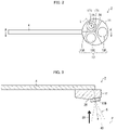
- Fig. 2 is a view schematically illustrating a nozzle 2 of the container 1.
- Fig. 3 is a cross-sectional view of a section taken along line A-A' of the nozzle 2 illustrated in Fig. 2 .
- Fig. 4 is a cross-sectional view illustrating an internal structure of a spraying part 13 of the nozzle 2.
- Fig. 5 is a view illustrating how a liquid 6 adheres to a spray target surface P on which the liquid 6 has been sprayed by using the nozzle 2.
- the hydrolyzing device 100 in accordance with Embodiment 1 is a device for cleaning emissions by supplying a denitration catalyst with a gas containing ammonia (NH 3 ) and decomposing nitrogen oxides contained in the emissions into nitrogen and water through a selective catalytic reduction (SCR) reaction using, as a reducing agent, the ammonia.
- the hydrolyzing device 100 includes the container 1, a bleed air line 101, a treatment gas line 102, and a heater (not illustrated).
- the heater heats a bleed air of exhaust from an engine such as a diesel engine.
- the bleed air having been heated is supplied to the container 1 through the bleed air line 101.
- the container 1 is a device for hydrolyzing the liquid 6 inside the container 1 to generate ammonia.
- the liquid 6 is an aqueous urea solution.
- the container 1 stores a spray target object 5, which is a catalyst for accelerating a hydrolysis reaction.
- the container 1 includes the nozzle 2 for spraying the spray target object 5 with the liquid 6.
- the container 1 further includes a pipe 4 for supporting the nozzle 2 and supplying the nozzle 2 with the liquid 6. The nozzle 2 is supplied with the liquid 6 through the pipe 4.
- the nozzle 2 sprays the spray target object 5 with the liquid 6.
- the liquid 6 having been sprayed is hydrolyzed by a hot gas (bleed air) introduced into the container 1 to form ammonia.
- the container 1 has a shape that include, as a specific example, the shape of an axially long tube, such as the shape of a rectangular tube that is substantially square in a cross section perpendicular to an extending direction thereof.
- the container 1 is not limited to the shape of a rectangular tube, but may be cylindrical.
- the container 1 supplies, through the treatment gas line 102, a hot treatment gas into which ammonia has been mixed.
- the nozzle 2 which is provided in the container 1, is a liquid spray nozzle for spraying (misting) the liquid 6 in the form of mist, over a spray target surface P of the spray target object 5.
- the nozzle 2 includes: a nozzle body 11 connected to the pipe 4; and at least three spraying parts 13 for spraying the liquid 6.
- Described as an example in Embodiment 1 is a case where the nozzle body 11 includes, as a spraying part 13, three spraying parts: a spraying part 13A; a spraying part 13B; and a spraying part 13C.
- Fig. 4 is a cross-sectional view illustrating the structure of the spraying part 13A of the nozzle 2.
- the spraying part 13A includes: a liquid spray hole 14; a gas supply portion 15; and gas ejecting parts 17 (route control part) paired together.
- the liquid spray hole 14 is a circular opening provided in the spraying part 13.
- the liquid spray hole 14 is connected to a liquid passage 141 inside the pipe 4, and sprays the liquid 6 carried by the liquid passage 141.
- the gas supply portion 15 includes: gas spray holes 151 serving as spray holes; and gas passages 152.
- the gas spray holes 151 are a pair of openings located near the liquid spray hole 14.
- the gas passages 152 are connected to a gas passage inside the pipe 4.
- the gas passages 152 supply a gas 50 carried by the gas passage to the gas spray holes 151, which spray the gas 50 toward the liquid 6 sprayed from the spraying part 13. This makes the particle diameter of the liquid 6 sprayed from the liquid spray hole 14 smaller, so that the liquid 6 becomes misty.
- the gas ejecting parts 17 are a mechanism for controlling a region (hereinafter, referred to also as adhesion region) formed through adhesion, to the spray target surface P, of the liquid 6 sprayed from the spraying part 13.
- adhesion region a region formed through adhesion, to the spray target surface P, of the liquid 6 sprayed from the spraying part 13.
- the spray target surface P is a flat surface substantially perpendicular to a direction in which the nozzle body 11 is viewed in a plan view.
- the gas ejecting parts 17 control a route of a liquid sprayed from the liquid spray hole 14 by blowing a gas toward the liquid sprayed from the liquid spray hole 14.
- the gas ejecting parts 17 include: gas spray holes 171; and gas passages 172. Each of the gas ejecting parts 17 paired together includes corresponding one of the gas spray holes 171.
- the gas spray holes 171 are a pair of openings provided near the end of the spraying part 13A, on a straight line L (a straight line denoted by a sign L in Fig. 2 ) connecting a center point 20 (see Fig. 2 ) of the nozzle body 11 and the spraying part 13A. As illustrated in Fig. 2 , the gas spray holes 171 paired together are disposed such that the liquid spray hole 14 is placed therebetween on the straight line L. In other words, the gas spray holes 171 paired together are provided in an outer circumferential part of the spraying part 13A and also on a straight line L passing through the center of the nozzle body 11 and the liquid spray hole 14.
- the gas passages 172 are connected to another gas passage that is different from the gas passage connected to the gas passages 152 and that is provided inside the pipe 4.
- the gas passages 172 supply the gas spray holes 171 with a gas 60 carried by the other gas passage.
- the gas passages 172 and the gas passages 152 can be connected to the same gas passage provided inside the pipe 4. In such a case, the gas spray holes 171 and the gas spray holes 151 are supplied with the gas 50 carried by the same gas passage.
- the gas spray holes 171 spray, with the gas 60 supplied by the gas passages 172, the liquid 6 that have been sprayed and have become misty.
- the gas 50 and the gas 60 sprayed from the gas spray holes 151 and the gas passage 17, respectively are not limited to any particular types.
- the gas 50 and the gas 60 may be, for example, air.
- the three spraying parts 13 are disposed so as not to be located in line with each other when seen from a third direction (a direction represented by an arrow 30 in Fig. 3 ) that is perpendicular to the spray target surface P. Specifically, the three spraying parts 13 are disposed on the circumference of the same circle having a center which is the center point 20 (a position represented by a dot 20 in Fig. 2 ), which is the center of the nozzle body 11, when seen from the third direction (in other words, in the plan view, from a position where the three spraying parts 13 are disposed, of the nozzle body 11).
- the three spraying parts 13 are disposed so as to be spaced at regular intervals. In other words, the three spraying parts 13 are disposed so as to form a regular triangle when seen from the third direction. Further, the three spraying parts 13 are disposed so as to be inclined with respect to a plane perpendicular to the third direction, so that, when seen from the third direction, the liquid is sprayed in directions from the center point 20 of the nozzle body 11 to the spraying parts 13 (for example, the direction represented by an arrow 40 in a case of the spraying part 13B in Fig. 3 ).
- the liquid 6 sprayed from the liquid spray hole 14 is deformed to be flattened (oval) as a whole, so as to be shorter in a direction in which the gas spray holes 171 face each other and longer in a direction perpendicular to the direction in which the gas spray holes 171 face each other.
- the gas ejecting parts 17 control a route of the liquid such that an adhesion region S is shorter in a first direction outward from a central part of a group of the plurality of adhesion regions S than in a second direction perpendicular to the first direction.
- the configuration described above makes flattened (oval) the adhesion region S (a region denoted by a sign S in Fig. 5 ) of the liquid 6 that is sprayed from each of the spraying parts 13 and then adheres to the spray target surface P, as illustrated in Fig. 5 .
- the adhesion region S is shorter in a first direction (a direction represented by an arrow 70 in Fig. 5 ) outward from the center (center point 20) of the nozzle body 11 than in a second direction (a direction represented by an arrow 80 in Fig. 5 ) perpendicular to the first direction.
- a region T (referred to as an adhesion region T) is a group of the adhesion regions S, in which the liquid having been sprayed from the three spraying parts 13 adheres to the spray target surface P.
- an end part of one adhesion region S (a region denoted by S in Fig. 5 ) produced by one of the spraying parts 13 overlaps an end part of another adhesion region S produced by another one of the spraying parts 13.
- the gas ejecting parts 17 control the route of the liquid such that the adhesion region S is shorter in the first direction outward from the central part of the adhesion region T than in the second direction perpendicular to the first direction.
- the spray region S generated by a single spraying part 13 is flattened, an adhesion amount of the liquid 6 is likely to be reduced, in particular, in end parts thereof in a longitudinal direction.
- the three spraying parts 13 generate the spray regions S each having end parts that overlap end parts of the other spray regions S. This reduces variation in the adhesion amount of the liquid 6 within the spray region T.
- Each of the spraying parts 13 is inclined outward from the nozzle body 11.
- the spraying parts 13 therefore spray the liquid 6 in a direction outward from the nozzle body 11. This reduces the variation in the adhesion amount of the liquid 6 within the adhesion region S more than in a case where the spraying parts 13 point in the third direction.
- the liquid 6 sprayed from the spraying parts 13 is mostly sprayed substantially in the third direction.
- the liquid 6 mostly passes through the inside of the honeycomb structure of a catalyst, which is the spray target object 5, without touching the inner wall surface of the honeycomb structure. This could reduce the efficiency of a catalyzed reaction.
- each of the spraying parts 13 is inclined outward from the nozzle body 11. This causes the liquid 6 sprayed from the spraying parts 13 to be sprayed in a direction inclined with respect to the third direction. Accordingly, the liquid 6 mostly touches the inner wall surface of the honeycomb structure of the spray target object 5. This improves the efficiency of the catalyzed reaction.
- the flattened shape is adjusted by means of wind pressure of a gas jetted from the gas spray holes 171. This enables adaptation by changing the wind pressure without changing the structure of the spraying parts 13, even in a case where a condition such as the size of the spray target surface P is changed.
- the route control part described in Embodiment 1 has the configuration that involves the gas ejecting parts 17.
- a method for controlling the shape of the adhesion region S is not limited to this.
- the route control part may be a liquid spray hole 14 that is deformed to be flattened so that the adhesion region S is adjusted to be flattened.
- Fig. 6 is a view schematically illustrating a nozzle 2A in accordance with Embodiment 2 of the present invention.
- Fig. 7 is a cross-sectional view of a section taken along line B-B' of the nozzle 2A illustrated in Fig. 6 .
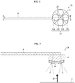
- Fig. 8 is a view illustrating a spray target surface P on which a liquid 6 has been sprayed by using the nozzle 2A.
- the nozzle 2A in accordance with Embodiment 2 of the present invention includes, as a spraying part 13, four spraying parts: spraying parts 13A, 13B, 13C, and 13D.
- the four spraying part 13A to 13D are disposed so as not to be located in line with each other when viewed from a third direction perpendicular to the spray target surface P.
- the four spraying parts 13 are disposed on the circumference of the same circle having a center which is a center point 20 of a nozzle body 11 when seen from the third direction.
- the four spraying parts 13 are disposed so as to be spaced at regular intervals. In other words, the four spraying parts 13 are disposed so as to form a regular triangle when seen from the third direction. Further, the four spraying parts 13 are disposed so as to be inclined with respect to a plane perpendicular to the third direction, so that, when seen from the third direction, the liquid is sprayed in directions from the center point 20 of the nozzle body 11 to the spraying parts 13.
- the nozzle 2A uses the nozzle 2A generates an adhesion region U of the liquid 6 (a region denoted by a sign U in Fig. 8 ) that is formed by four adhesion regions S. Accordingly, the adhesion region U is larger than the adhesion region T generated by using the nozzle 2. This is because the nozzle 2A includes the four spraying parts 13A to 13D. With the above configuration, the nozzle 2A enables both a reduction in the variation in an adhesion amount of the liquid 6 within the adhesion region T, as with the case of the nozzle 2, and spray of the liquid 6 in the spray region P over a larger range.
Landscapes
- Engineering & Computer Science (AREA)
- Chemical & Material Sciences (AREA)
- Combustion & Propulsion (AREA)
- Mechanical Engineering (AREA)
- General Engineering & Computer Science (AREA)
- Chemical Kinetics & Catalysis (AREA)
- Health & Medical Sciences (AREA)
- Toxicology (AREA)
- Nozzles (AREA)
- Exhaust Gas After Treatment (AREA)
- Details Or Accessories Of Spraying Plant Or Apparatus (AREA)
Abstract
Description
- The present invention relates to a nozzle and a hydrolyzing device.
- There is a conventionally-known system for cleaning emissions by decomposing nitrogen oxides contained in the emissions into nitrogen and water through a selective catalytic reduction (SCR) using, as a reducing agent, ammonia (NH3) obtained by hydrolyzing an aqueous urea solution. What is being demanded in such a system is an improvement in the efficiency of a hydrolysis reaction of an aqueous urea solution to form ammonia by spraying the catalyst with the aqueous urea solution.
- A variety of nozzles for misting a liquid over a spray target object are put into practical use. For example, Patent Literature 1 discloses a fluid spray nozzle having two orifices disposed parallel to each other in a width direction thereof and for spraying a fluid from each of the orifices.
- [Patent Literature 1]
Japanese Patent Application Publication, Tokukai, No. 2003-93926 - The inventors have found that it is important, for a method of efficiently hydrolyzing an aqueous urea solution into NH3, to evenly spray an aqueous urea solution on a certain cross-sectional surface of a spray target object, which is a catalyst. The inventors tried to achieve such spraying by using the nozzle as described above.
- However, when three or more spraying parts are provided in the nozzle as described above, the amount of liquid adhering to a spray target surface can vary from position to position. Therefore, there still remains room for improvement in evenness of an adhesion amount of a liquid sprayed on a spray target object by using a conventional nozzle.
- It is an object of an aspect of the present invention to improve evenness of an adhesion amount of a liquid sprayed on a spray target object by using a nozzle including three or more spraying parts.
- In order to solve the above problem, provided is a nozzle in accordance with an aspect of the present invention including: a nozzle body; and at least three spraying parts provided in the nozzle body and for spraying a liquid on a spray target surface, the at least three spraying parts being disposed so as not to be in line with each other in a plan view, from a position where the at least three spraying parts are disposed, of the nozzle body, the at least three spraying parts each including: a spray hole through which the liquid is sprayed outward from the nozzle body; and a route control part for controlling a route of the liquid sprayed from the spray hole, the liquid sprayed from the spray hole adhering to the spray target surface to form an adhesion region, the route control part controlling the route of the liquid such that the adhesion region is shorter in a first direction outward from a central part of a group of a plurality of adhesion regions, the plurality of adhesion regions each being the adhesion region, than in a second direction perpendicular to the first direction.
- An aspect of the present invention enables an improvement in evenness of an adhesion amount of a liquid sprayed on a spray target object by using a nozzle including three or more spraying parts.
-
-
Fig. 1 is a view schematically illustrating a configuration of a hydrolyzing device, including a container, in accordance with Embodiment 1 of the present invention. -
Fig. 2 is a view schematically illustrating a nozzle of the container. -
Fig. 3 is a cross-sectional view of a section taken along line A-A' of the nozzle illustrated inFig. 2 . -
Fig. 4 is a view schematically illustrating an internal structure of a spraying part of the nozzle. -
Fig. 5 is a view illustrating a spray target surface on which a liquid has been sprayed by using the nozzle. -
Fig. 6 is a view schematically illustrating a nozzle in accordance withEmbodiment 2 of the present invention. -
Fig. 7 is a cross-sectional view of a section taken along line B-B' of the nozzle illustrated inFig. 6 . -
Fig. 8 is a view illustrating a spray target surface on which a liquid has been sprayed by using the nozzle. - The following description will discuss an embodiment of the present invention with reference to
Figs. 1 to 5 in detail.Fig. 1 is a view schematically illustrating a configuration of a hydrolyzing device 100, including a container 1, in accordance with Embodiment 1 of the present invention.Fig. 2 is a view schematically illustrating anozzle 2 of the container 1.Fig. 3 is a cross-sectional view of a section taken along line A-A' of thenozzle 2 illustrated inFig. 2 .Fig. 4 is a cross-sectional view illustrating an internal structure of a sprayingpart 13 of thenozzle 2.Fig. 5 is a view illustrating how aliquid 6 adheres to a spray target surface P on which theliquid 6 has been sprayed by using thenozzle 2. - The hydrolyzing device 100 in accordance with Embodiment 1 is a device for cleaning emissions by supplying a denitration catalyst with a gas containing ammonia (NH3) and decomposing nitrogen oxides contained in the emissions into nitrogen and water through a selective catalytic reduction (SCR) reaction using, as a reducing agent, the ammonia. As illustrated in
Fig. 1 , the hydrolyzing device 100 includes the container 1, ableed air line 101, atreatment gas line 102, and a heater (not illustrated). - The heater heats a bleed air of exhaust from an engine such as a diesel engine. The bleed air having been heated is supplied to the container 1 through the
bleed air line 101. - The container 1 is a device for hydrolyzing the
liquid 6 inside the container 1 to generate ammonia. For example, theliquid 6 is an aqueous urea solution. The container 1 stores aspray target object 5, which is a catalyst for accelerating a hydrolysis reaction. The container 1 includes thenozzle 2 for spraying thespray target object 5 with theliquid 6. The container 1 further includes apipe 4 for supporting thenozzle 2 and supplying thenozzle 2 with theliquid 6. Thenozzle 2 is supplied with theliquid 6 through thepipe 4. - The
nozzle 2 sprays thespray target object 5 with theliquid 6. Theliquid 6 having been sprayed is hydrolyzed by a hot gas (bleed air) introduced into the container 1 to form ammonia. - The container 1 has a shape that include, as a specific example, the shape of an axially long tube, such as the shape of a rectangular tube that is substantially square in a cross section perpendicular to an extending direction thereof. However, the container 1 is not limited to the shape of a rectangular tube, but may be cylindrical. The container 1 supplies, through the
treatment gas line 102, a hot treatment gas into which ammonia has been mixed. - The
nozzle 2, which is provided in the container 1, is a liquid spray nozzle for spraying (misting) theliquid 6 in the form of mist, over a spray target surface P of thespray target object 5. As illustrated inFigs. 2 and 3 , thenozzle 2 includes: anozzle body 11 connected to thepipe 4; and at least three sprayingparts 13 for spraying theliquid 6. Described as an example in Embodiment 1 is a case where thenozzle body 11 includes, as a sprayingpart 13, three spraying parts: a sprayingpart 13A; a sprayingpart 13B; and a sprayingpart 13C. - The spraying
parts 13A to 13C have the same structure. Therefore, in the following description, only the structure of the sprayingpart 13A is described and the descriptions of the structures of the sprayingpart 13B and the sprayingpart 13C will be omitted.Fig. 4 is a cross-sectional view illustrating the structure of the sprayingpart 13A of thenozzle 2. As illustrated inFig. 4 , the sprayingpart 13A includes: aliquid spray hole 14; agas supply portion 15; and gas ejecting parts 17 (route control part) paired together. Theliquid spray hole 14 is a circular opening provided in the sprayingpart 13. Theliquid spray hole 14 is connected to aliquid passage 141 inside thepipe 4, and sprays theliquid 6 carried by theliquid passage 141. - The
gas supply portion 15 includes:gas spray holes 151 serving as spray holes; andgas passages 152. Thegas spray holes 151 are a pair of openings located near theliquid spray hole 14. Thegas passages 152 are connected to a gas passage inside thepipe 4. Thegas passages 152 supply agas 50 carried by the gas passage to thegas spray holes 151, which spray thegas 50 toward theliquid 6 sprayed from the sprayingpart 13. This makes the particle diameter of theliquid 6 sprayed from theliquid spray hole 14 smaller, so that theliquid 6 becomes misty. - The
gas ejecting parts 17 are a mechanism for controlling a region (hereinafter, referred to also as adhesion region) formed through adhesion, to the spray target surface P, of the liquid 6 sprayed from the sprayingpart 13. Note that the spray target surface P is a flat surface substantially perpendicular to a direction in which thenozzle body 11 is viewed in a plan view. - The
gas ejecting parts 17 control a route of a liquid sprayed from theliquid spray hole 14 by blowing a gas toward the liquid sprayed from theliquid spray hole 14. Thegas ejecting parts 17 include: gas spray holes 171; andgas passages 172. Each of thegas ejecting parts 17 paired together includes corresponding one of the gas spray holes 171. - The gas spray holes 171 are a pair of openings provided near the end of the spraying
part 13A, on a straight line L (a straight line denoted by a sign L inFig. 2 ) connecting a center point 20 (seeFig. 2 ) of thenozzle body 11 and the sprayingpart 13A. As illustrated inFig. 2 , the gas spray holes 171 paired together are disposed such that theliquid spray hole 14 is placed therebetween on the straight line L. In other words, the gas spray holes 171 paired together are provided in an outer circumferential part of the sprayingpart 13A and also on a straight line L passing through the center of thenozzle body 11 and theliquid spray hole 14. - The
gas passages 172 are connected to another gas passage that is different from the gas passage connected to thegas passages 152 and that is provided inside thepipe 4. Thegas passages 172 supply the gas spray holes 171 with agas 60 carried by the other gas passage. It should be noted that thegas passages 172 and thegas passages 152 can be connected to the same gas passage provided inside thepipe 4. In such a case, the gas spray holes 171 and the gas spray holes 151 are supplied with thegas 50 carried by the same gas passage. - The gas spray holes 171 spray, with the
gas 60 supplied by thegas passages 172, theliquid 6 that have been sprayed and have become misty. Note that thegas 50 and thegas 60 sprayed from the gas spray holes 151 and thegas passage 17, respectively are not limited to any particular types. Thegas 50 and thegas 60 may be, for example, air. - The three spraying
parts 13 are disposed so as not to be located in line with each other when seen from a third direction (a direction represented by anarrow 30 inFig. 3 ) that is perpendicular to the spray target surface P. Specifically, the three sprayingparts 13 are disposed on the circumference of the same circle having a center which is the center point 20 (a position represented by adot 20 inFig. 2 ), which is the center of thenozzle body 11, when seen from the third direction (in other words, in the plan view, from a position where the three sprayingparts 13 are disposed, of the nozzle body 11). - The three spraying
parts 13 are disposed so as to be spaced at regular intervals. In other words, the three sprayingparts 13 are disposed so as to form a regular triangle when seen from the third direction. Further, the three sprayingparts 13 are disposed so as to be inclined with respect to a plane perpendicular to the third direction, so that, when seen from the third direction, the liquid is sprayed in directions from thecenter point 20 of thenozzle body 11 to the spraying parts 13 (for example, the direction represented by anarrow 40 in a case of the sprayingpart 13B inFig. 3 ). - According to the
nozzle 2 of Embodiment 1, with the pressure of thegas 60 sprayed by the gas spray holes 171 of thegas ejecting parts 17, theliquid 6 sprayed from theliquid spray hole 14 is deformed to be flattened (oval) as a whole, so as to be shorter in a direction in which the gas spray holes 171 face each other and longer in a direction perpendicular to the direction in which the gas spray holes 171 face each other. This means thegas ejecting parts 17 control a route of the liquid such that an adhesion region S is shorter in a first direction outward from a central part of a group of the plurality of adhesion regions S than in a second direction perpendicular to the first direction. - The configuration described above makes flattened (oval) the adhesion region S (a region denoted by a sign S in
Fig. 5 ) of the liquid 6 that is sprayed from each of the sprayingparts 13 and then adheres to the spray target surface P, as illustrated inFig. 5 . In other words, the adhesion region S is shorter in a first direction (a direction represented by anarrow 70 inFig. 5 ) outward from the center (center point 20) of thenozzle body 11 than in a second direction (a direction represented by anarrow 80 inFig. 5 ) perpendicular to the first direction. - As illustrated in
Fig. 5 , a region T (referred to as an adhesion region T) is a group of the adhesion regions S, in which the liquid having been sprayed from the three sprayingparts 13 adheres to the spray target surface P. In the region T, an end part of one adhesion region S (a region denoted by S inFig. 5 ) produced by one of the sprayingparts 13 overlaps an end part of another adhesion region S produced by another one of the sprayingparts 13. Thegas ejecting parts 17 control the route of the liquid such that the adhesion region S is shorter in the first direction outward from the central part of the adhesion region T than in the second direction perpendicular to the first direction. - Since the spray region S generated by a
single spraying part 13 is flattened, an adhesion amount of theliquid 6 is likely to be reduced, in particular, in end parts thereof in a longitudinal direction. However, according to thenozzle 2, the three sprayingparts 13 generate the spray regions S each having end parts that overlap end parts of the other spray regions S. This reduces variation in the adhesion amount of theliquid 6 within the spray region T. - Each of the spraying
parts 13 is inclined outward from thenozzle body 11. The sprayingparts 13 therefore spray theliquid 6 in a direction outward from thenozzle body 11. This reduces the variation in the adhesion amount of theliquid 6 within the adhesion region S more than in a case where the sprayingparts 13 point in the third direction. - In a case where the spraying
parts 13 face, in the third direction, thespray target object 5 that has a honeycomb structure, theliquid 6 sprayed from the sprayingparts 13 is mostly sprayed substantially in the third direction. In this case, theliquid 6 mostly passes through the inside of the honeycomb structure of a catalyst, which is thespray target object 5, without touching the inner wall surface of the honeycomb structure. This could reduce the efficiency of a catalyzed reaction. - In contrast, according to the
nozzle 2 in accordance with Embodiment 1, each of the sprayingparts 13 is inclined outward from thenozzle body 11. This causes theliquid 6 sprayed from the sprayingparts 13 to be sprayed in a direction inclined with respect to the third direction. Accordingly, theliquid 6 mostly touches the inner wall surface of the honeycomb structure of thespray target object 5. This improves the efficiency of the catalyzed reaction. - In the spraying
parts 13, the flattened shape is adjusted by means of wind pressure of a gas jetted from the gas spray holes 171. This enables adaptation by changing the wind pressure without changing the structure of the sprayingparts 13, even in a case where a condition such as the size of the spray target surface P is changed. - The route control part described in Embodiment 1 has the configuration that involves the
gas ejecting parts 17. However, a method for controlling the shape of the adhesion region S is not limited to this. For example, the route control part may be aliquid spray hole 14 that is deformed to be flattened so that the adhesion region S is adjusted to be flattened. - The following description will discuss another embodiment of the present invention with reference to
Figs. 6 to 8 . For the convenience of description, a member having the same function as the member already described in Embodiment 1 is assigned with the same reference sign, and the description thereof is omitted.Fig. 6 is a view schematically illustrating anozzle 2A in accordance withEmbodiment 2 of the present invention.Fig. 7 is a cross-sectional view of a section taken along line B-B' of thenozzle 2A illustrated inFig. 6 .Fig. 8 is a view illustrating a spray target surface P on which aliquid 6 has been sprayed by using thenozzle 2A. - As illustrated in
Figs. 6 and 7 , thenozzle 2A in accordance withEmbodiment 2 of the present invention includes, as a sprayingpart 13, four spraying parts: sprayingparts part 13A to 13D are disposed so as not to be located in line with each other when viewed from a third direction perpendicular to the spray target surface P. Specifically, the four sprayingparts 13 are disposed on the circumference of the same circle having a center which is acenter point 20 of anozzle body 11 when seen from the third direction. - The four
spraying parts 13 are disposed so as to be spaced at regular intervals. In other words, the four sprayingparts 13 are disposed so as to form a regular triangle when seen from the third direction. Further, the four sprayingparts 13 are disposed so as to be inclined with respect to a plane perpendicular to the third direction, so that, when seen from the third direction, the liquid is sprayed in directions from thecenter point 20 of thenozzle body 11 to the sprayingparts 13. - As illustrated in
Fig. 8 , using thenozzle 2A generates an adhesion region U of the liquid 6 (a region denoted by a sign U inFig. 8 ) that is formed by four adhesion regions S. Accordingly, the adhesion region U is larger than the adhesion region T generated by using thenozzle 2. This is because thenozzle 2A includes the fourspraying parts 13A to 13D. With the above configuration, thenozzle 2A enables both a reduction in the variation in an adhesion amount of theliquid 6 within the adhesion region T, as with the case of thenozzle 2, and spray of the liquid 6 in the spray region P over a larger range. -
- 2, 2A: Nozzle
- 5: Spray target object
- 6: Liquid
- 11: Nozzle body
- 13, 13A, 13B, 13C, 13D: Spraying part
- 14: Liquid spray hole (spray hole)
- 17: Gas ejecting part (route control part)
- P: Spray target surface
Claims (5)
- A nozzle comprising:a nozzle body; andat least three spraying parts provided in the nozzle body and for spraying a liquid on a spray target surface,the at least three spraying parts being disposed so as not to be in line with each other in a plan view, from a position where the at least three spraying parts are disposed, of the nozzle body,the at least three spraying parts each including:a spray hole through which the liquid is sprayed outward from the nozzle body; anda route control part for controlling a route of the liquid sprayed from the spray hole,the liquid sprayed from the spray hole adhering to the spray target surface to form an adhesion region,the route control part controlling the route of the liquid such that the adhesion region is shorter in a first direction outward from a central part of a group of a plurality of adhesion regions, the plurality of adhesion regions each being the adhesion region, than in a second direction perpendicular to the first direction.
- The nozzle according to claim 1, wherein the nozzle comprises, as the route control part, gas ejecting parts paired together for blowing a gas toward the liquid sprayed from the spray hole.
- The nozzle according to claim 2, wherein the gas ejecting parts paired together each include a gas spray hole for spraying the gas, and
the gas spray hole is provided in an outer circumferential part of a corresponding one of the at least three spraying parts and on a straight line passing through the center of the nozzle body and the spray hole. - The nozzle according to any one of claims 1 to 3, wherein the at least three spraying parts are spaced at regular intervals on the circumference of the same circle having a center that is the center of the nozzle body.
- A hydrolyzing device comprising:a container for storing a catalyst for accelerating a hydrolysis reaction;a nozzle according to any one of claims 1 to 4 provided inside the container and for spraying the catalyst with an aqueous urea solution as the liquid; anda pipe for supplying the nozzle with the aqueous urea solution.
Applications Claiming Priority (2)
| Application Number | Priority Date | Filing Date | Title |
|---|---|---|---|
| JP2019208835A JP7181178B2 (en) | 2019-11-19 | 2019-11-19 | Nozzle and hydrolyzer |
| PCT/JP2020/025744 WO2021100236A1 (en) | 2019-11-19 | 2020-07-01 | Nozzle and hydrolyzing device |
Publications (3)
| Publication Number | Publication Date |
|---|---|
| EP4063018A1 true EP4063018A1 (en) | 2022-09-28 |
| EP4063018A4 EP4063018A4 (en) | 2023-11-15 |
| EP4063018B1 EP4063018B1 (en) | 2024-09-04 |
Family
ID=75966106
Family Applications (1)
| Application Number | Title | Priority Date | Filing Date |
|---|---|---|---|
| EP20890230.4A Active EP4063018B1 (en) | 2019-11-19 | 2020-07-01 | Nozzle and hydrolyzing device |
Country Status (6)
| Country | Link |
|---|---|
| EP (1) | EP4063018B1 (en) |
| JP (1) | JP7181178B2 (en) |
| KR (1) | KR102894198B1 (en) |
| CN (1) | CN114746185B (en) |
| DK (1) | DK4063018T3 (en) |
| WO (1) | WO2021100236A1 (en) |
Families Citing this family (1)
| Publication number | Priority date | Publication date | Assignee | Title |
|---|---|---|---|---|
| KR102858224B1 (en) * | 2022-09-21 | 2025-09-11 | 한국화학연구원 | Hydrogenation reactor and hydrogenation method for preventing oligomerization of furfuryl alcohol |
Family Cites Families (19)
| Publication number | Priority date | Publication date | Assignee | Title |
|---|---|---|---|---|
| JP3307771B2 (en) * | 1993-08-23 | 2002-07-24 | ハンス‐ユルゲン、ガイドール | Means for descaling hot rolled steel sheets |
| JP2002066393A (en) * | 2000-08-25 | 2002-03-05 | Freunt Ind Co Ltd | Multi-head type spray gun, coating apparatus using the same, and coating method |
| JP2003093926A (en) | 2001-09-21 | 2003-04-02 | Kyoritsu Gokin Co Ltd | Fluid injection nozzle |
| JP2004033840A (en) * | 2002-07-01 | 2004-02-05 | Yoshiyuki Nagae | Sprayer |
| JP2004195335A (en) * | 2002-12-17 | 2004-07-15 | Kyowa Kogyo Kk | Diffusion spray nozzle |
| DE102004029679A1 (en) * | 2004-06-18 | 2005-12-29 | Purem Abgassysteme Gmbh & Co. Kg | Injection nozzle especially for introducing of urea into exhaust gas of internal combustion engine has nozzle cap with several orifices, with ratio of orifice diameter to orifice length being greater than 1 |
| BRPI0807909B1 (en) * | 2007-02-13 | 2020-11-24 | Bete Fog Nozzle, Inc. | spray nozzles |
| JP2010090836A (en) * | 2008-10-09 | 2010-04-22 | Denso Corp | Urea water supply equipment |
| DE102009005528A1 (en) * | 2009-01-20 | 2010-07-22 | Albonair Gmbh | Dual-component nozzle for injecting a fluid e.g. urea solution into an exhaust gas system of an internal combustion engine for selective catalytic reduction, comprises first nozzle opening, and second nozzle opening formed by annular gap |
| DE102009034072A1 (en) * | 2009-07-22 | 2011-01-27 | Emitec Gesellschaft Für Emissionstechnologie Mbh | Injector for the supply of reducing agent and apparatus for the treatment of exhaust gases |
| JP2011117386A (en) * | 2009-12-04 | 2011-06-16 | Volvo Powertrain Ab | Engine exhaust emission control device |
| JP2013002336A (en) * | 2011-06-15 | 2013-01-07 | Toyota Industries Corp | Reducing agent injection nozzle and nitrogen oxide purification system with reducing agent injection nozzle |
| WO2013094522A1 (en) * | 2011-12-19 | 2013-06-27 | ノズルネットワーク株式会社 | Liquid atomization device |
| CN104069968B (en) * | 2013-03-28 | 2017-01-04 | 株式会社Enjet | Spray nozzle and the application system of this spray nozzle of use |
| EP2826973B1 (en) * | 2013-07-18 | 2017-10-25 | FPT Motorenforschung AG | System for preventing the urea crystal formation within an exhaust gas after treatment system |
| US10473013B2 (en) * | 2014-09-26 | 2019-11-12 | Cummins Emission Solutions, Inc. | Integrative reductant system and method using constant volume injection |
| CN204220334U (en) * | 2014-10-13 | 2015-03-25 | 北京洛卡环保技术有限公司 | A kind of denitrating flue gas directly sprays spraying urea liquid emitter |
| WO2017015373A1 (en) * | 2015-07-20 | 2017-01-26 | Spraying Systems Co. | Improved steam atomizing liquid spray nozzle assembly |
| JP2019027347A (en) * | 2017-07-28 | 2019-02-21 | いすゞ自動車株式会社 | Aftertreatment device |
-
2019
- 2019-11-19 JP JP2019208835A patent/JP7181178B2/en active Active
-
2020
- 2020-07-01 WO PCT/JP2020/025744 patent/WO2021100236A1/en not_active Ceased
- 2020-07-01 DK DK20890230.4T patent/DK4063018T3/en active
- 2020-07-01 KR KR1020227019336A patent/KR102894198B1/en active Active
- 2020-07-01 CN CN202080080181.7A patent/CN114746185B/en active Active
- 2020-07-01 EP EP20890230.4A patent/EP4063018B1/en active Active
Also Published As
| Publication number | Publication date |
|---|---|
| EP4063018B1 (en) | 2024-09-04 |
| DK4063018T3 (en) | 2024-09-16 |
| CN114746185A (en) | 2022-07-12 |
| JP7181178B2 (en) | 2022-11-30 |
| CN114746185B (en) | 2023-06-16 |
| JP2021079333A (en) | 2021-05-27 |
| KR20220100908A (en) | 2022-07-18 |
| KR102894198B1 (en) | 2025-12-01 |
| WO2021100236A1 (en) | 2021-05-27 |
| EP4063018A4 (en) | 2023-11-15 |
Similar Documents
| Publication | Publication Date | Title |
|---|---|---|
| US8173088B2 (en) | Method, system and apparatus for liquid injection into a gas system | |
| JP4605205B2 (en) | Exhaust purification device | |
| US8528884B2 (en) | Injection nozzle for supplying reducing agent and device for treating exhaust gases | |
| RU2669982C2 (en) | Exhaust gas line section for supplying liquid additive | |
| EP2312135B1 (en) | Liquid reducing agent injection nozzle | |
| US20100170234A1 (en) | Injector Mounting Configuration for an Exhaust Treatment System | |
| CN102022165B (en) | Hybrid unit of SCR (selective catalytic reduction) system for vehicle urea | |
| JP6108427B2 (en) | Urea water injection nozzle | |
| JP5937517B2 (en) | Dosing module that administers urea-based reducing agent to the exhaust gas stream | |
| KR20010090608A (en) | Device for impinging a flowing gas with a reactant | |
| CN102094699A (en) | Static mixer for diesel engine urea selective catalytic reduction device | |
| CN105822396A (en) | Urea mixing device and SCR (Selective Catalytic Reduction) system | |
| CN202028346U (en) | Static mixer for urea selective catalytic reduction device of diesel engine | |
| EP4063018B1 (en) | Nozzle and hydrolyzing device | |
| EP2342432B1 (en) | Urea injector nozzle | |
| JP5170974B2 (en) | Flue gas denitration equipment | |
| US10273849B2 (en) | Injection module and exhaust system having an injection module | |
| CN102242661A (en) | Static mixer of vehicle selective catalytic reduction (SCR) device | |
| CN113302384A (en) | Reducing agent nozzle | |
| US20180142596A1 (en) | Injection module and exhaust system having an injection module | |
| JP2013002336A (en) | Reducing agent injection nozzle and nitrogen oxide purification system with reducing agent injection nozzle | |
| CN220621994U (en) | Mixer and aftertreatment system | |
| CN219242023U (en) | A urea nozzle and SCR urea injection system | |
| CN220621996U (en) | Mixer and aftertreatment system | |
| EP3385516A1 (en) | Scr system and methodè |
Legal Events
| Date | Code | Title | Description |
|---|---|---|---|
| STAA | Information on the status of an ep patent application or granted ep patent |
Free format text: STATUS: THE INTERNATIONAL PUBLICATION HAS BEEN MADE |
|
| PUAI | Public reference made under article 153(3) epc to a published international application that has entered the european phase |
Free format text: ORIGINAL CODE: 0009012 |
|
| STAA | Information on the status of an ep patent application or granted ep patent |
Free format text: STATUS: REQUEST FOR EXAMINATION WAS MADE |
|
| 17P | Request for examination filed |
Effective date: 20220517 |
|
| AK | Designated contracting states |
Kind code of ref document: A1 Designated state(s): AL AT BE BG CH CY CZ DE DK EE ES FI FR GB GR HR HU IE IS IT LI LT LU LV MC MK MT NL NO PL PT RO RS SE SI SK SM TR |
|
| DAV | Request for validation of the european patent (deleted) | ||
| DAX | Request for extension of the european patent (deleted) | ||
| REG | Reference to a national code |
Ref country code: DE Ref legal event code: R079 Free format text: PREVIOUS MAIN CLASS: B05B0007080000 Ipc: B05B0007060000 Ref country code: DE Ref legal event code: R079 Ref document number: 602020037323 Country of ref document: DE Free format text: PREVIOUS MAIN CLASS: B05B0007080000 Ipc: B05B0007060000 |
|
| A4 | Supplementary search report drawn up and despatched |
Effective date: 20231018 |
|
| RIC1 | Information provided on ipc code assigned before grant |
Ipc: B05B 7/00 20060101ALI20231012BHEP Ipc: F01N 3/10 20060101ALI20231012BHEP Ipc: F01N 3/20 20060101ALI20231012BHEP Ipc: F01N 3/08 20060101ALI20231012BHEP Ipc: B05B 7/08 20060101ALI20231012BHEP Ipc: B05B 7/06 20060101AFI20231012BHEP |
|
| GRAP | Despatch of communication of intention to grant a patent |
Free format text: ORIGINAL CODE: EPIDOSNIGR1 |
|
| STAA | Information on the status of an ep patent application or granted ep patent |
Free format text: STATUS: GRANT OF PATENT IS INTENDED |
|
| INTG | Intention to grant announced |
Effective date: 20240617 |
|
| GRAS | Grant fee paid |
Free format text: ORIGINAL CODE: EPIDOSNIGR3 |
|
| GRAA | (expected) grant |
Free format text: ORIGINAL CODE: 0009210 |
|
| STAA | Information on the status of an ep patent application or granted ep patent |
Free format text: STATUS: THE PATENT HAS BEEN GRANTED |
|
| P01 | Opt-out of the competence of the unified patent court (upc) registered |
Free format text: CASE NUMBER: APP_39168/2024 Effective date: 20240701 |
|
| AK | Designated contracting states |
Kind code of ref document: B1 Designated state(s): AL AT BE BG CH CY CZ DE DK EE ES FI FR GB GR HR HU IE IS IT LI LT LU LV MC MK MT NL NO PL PT RO RS SE SI SK SM TR |
|
| REG | Reference to a national code |
Ref country code: GB Ref legal event code: FG4D |
|
| REG | Reference to a national code |
Ref country code: CH Ref legal event code: EP |
|
| REG | Reference to a national code |
Ref country code: DK Ref legal event code: T3 Effective date: 20240911 |
|
| REG | Reference to a national code |
Ref country code: IE Ref legal event code: FG4D |
|
| REG | Reference to a national code |
Ref country code: DE Ref legal event code: R096 Ref document number: 602020037323 Country of ref document: DE |
|
| REG | Reference to a national code |
Ref country code: LT Ref legal event code: MG9D |
|
| REG | Reference to a national code |
Ref country code: NL Ref legal event code: MP Effective date: 20240904 |
|
| PG25 | Lapsed in a contracting state [announced via postgrant information from national office to epo] |
Ref country code: NO Free format text: LAPSE BECAUSE OF FAILURE TO SUBMIT A TRANSLATION OF THE DESCRIPTION OR TO PAY THE FEE WITHIN THE PRESCRIBED TIME-LIMIT Effective date: 20241204 |
|
| PG25 | Lapsed in a contracting state [announced via postgrant information from national office to epo] |
Ref country code: PL Free format text: LAPSE BECAUSE OF FAILURE TO SUBMIT A TRANSLATION OF THE DESCRIPTION OR TO PAY THE FEE WITHIN THE PRESCRIBED TIME-LIMIT Effective date: 20240904 Ref country code: GR Free format text: LAPSE BECAUSE OF FAILURE TO SUBMIT A TRANSLATION OF THE DESCRIPTION OR TO PAY THE FEE WITHIN THE PRESCRIBED TIME-LIMIT Effective date: 20241205 Ref country code: FI Free format text: LAPSE BECAUSE OF FAILURE TO SUBMIT A TRANSLATION OF THE DESCRIPTION OR TO PAY THE FEE WITHIN THE PRESCRIBED TIME-LIMIT Effective date: 20240904 |
|
| PG25 | Lapsed in a contracting state [announced via postgrant information from national office to epo] |
Ref country code: BG Free format text: LAPSE BECAUSE OF FAILURE TO SUBMIT A TRANSLATION OF THE DESCRIPTION OR TO PAY THE FEE WITHIN THE PRESCRIBED TIME-LIMIT Effective date: 20240904 |
|
| PG25 | Lapsed in a contracting state [announced via postgrant information from national office to epo] |
Ref country code: LV Free format text: LAPSE BECAUSE OF FAILURE TO SUBMIT A TRANSLATION OF THE DESCRIPTION OR TO PAY THE FEE WITHIN THE PRESCRIBED TIME-LIMIT Effective date: 20240904 |
|
| PG25 | Lapsed in a contracting state [announced via postgrant information from national office to epo] |
Ref country code: HR Free format text: LAPSE BECAUSE OF FAILURE TO SUBMIT A TRANSLATION OF THE DESCRIPTION OR TO PAY THE FEE WITHIN THE PRESCRIBED TIME-LIMIT Effective date: 20240904 |
|
| PG25 | Lapsed in a contracting state [announced via postgrant information from national office to epo] |
Ref country code: ES Free format text: LAPSE BECAUSE OF FAILURE TO SUBMIT A TRANSLATION OF THE DESCRIPTION OR TO PAY THE FEE WITHIN THE PRESCRIBED TIME-LIMIT Effective date: 20240904 Ref country code: RS Free format text: LAPSE BECAUSE OF FAILURE TO SUBMIT A TRANSLATION OF THE DESCRIPTION OR TO PAY THE FEE WITHIN THE PRESCRIBED TIME-LIMIT Effective date: 20241204 |
|
| PG25 | Lapsed in a contracting state [announced via postgrant information from national office to epo] |
Ref country code: RS Free format text: LAPSE BECAUSE OF FAILURE TO SUBMIT A TRANSLATION OF THE DESCRIPTION OR TO PAY THE FEE WITHIN THE PRESCRIBED TIME-LIMIT Effective date: 20241204 Ref country code: PL Free format text: LAPSE BECAUSE OF FAILURE TO SUBMIT A TRANSLATION OF THE DESCRIPTION OR TO PAY THE FEE WITHIN THE PRESCRIBED TIME-LIMIT Effective date: 20240904 Ref country code: NO Free format text: LAPSE BECAUSE OF FAILURE TO SUBMIT A TRANSLATION OF THE DESCRIPTION OR TO PAY THE FEE WITHIN THE PRESCRIBED TIME-LIMIT Effective date: 20241204 Ref country code: LV Free format text: LAPSE BECAUSE OF FAILURE TO SUBMIT A TRANSLATION OF THE DESCRIPTION OR TO PAY THE FEE WITHIN THE PRESCRIBED TIME-LIMIT Effective date: 20240904 Ref country code: HR Free format text: LAPSE BECAUSE OF FAILURE TO SUBMIT A TRANSLATION OF THE DESCRIPTION OR TO PAY THE FEE WITHIN THE PRESCRIBED TIME-LIMIT Effective date: 20240904 Ref country code: GR Free format text: LAPSE BECAUSE OF FAILURE TO SUBMIT A TRANSLATION OF THE DESCRIPTION OR TO PAY THE FEE WITHIN THE PRESCRIBED TIME-LIMIT Effective date: 20241205 Ref country code: FI Free format text: LAPSE BECAUSE OF FAILURE TO SUBMIT A TRANSLATION OF THE DESCRIPTION OR TO PAY THE FEE WITHIN THE PRESCRIBED TIME-LIMIT Effective date: 20240904 Ref country code: ES Free format text: LAPSE BECAUSE OF FAILURE TO SUBMIT A TRANSLATION OF THE DESCRIPTION OR TO PAY THE FEE WITHIN THE PRESCRIBED TIME-LIMIT Effective date: 20240904 Ref country code: BG Free format text: LAPSE BECAUSE OF FAILURE TO SUBMIT A TRANSLATION OF THE DESCRIPTION OR TO PAY THE FEE WITHIN THE PRESCRIBED TIME-LIMIT Effective date: 20240904 |
|
| REG | Reference to a national code |
Ref country code: AT Ref legal event code: MK05 Ref document number: 1719805 Country of ref document: AT Kind code of ref document: T Effective date: 20240904 |
|
| PG25 | Lapsed in a contracting state [announced via postgrant information from national office to epo] |
Ref country code: NL Free format text: LAPSE BECAUSE OF FAILURE TO SUBMIT A TRANSLATION OF THE DESCRIPTION OR TO PAY THE FEE WITHIN THE PRESCRIBED TIME-LIMIT Effective date: 20240904 |
|
| PG25 | Lapsed in a contracting state [announced via postgrant information from national office to epo] |
Ref country code: PT Free format text: LAPSE BECAUSE OF FAILURE TO SUBMIT A TRANSLATION OF THE DESCRIPTION OR TO PAY THE FEE WITHIN THE PRESCRIBED TIME-LIMIT Effective date: 20250106 Ref country code: IS Free format text: LAPSE BECAUSE OF FAILURE TO SUBMIT A TRANSLATION OF THE DESCRIPTION OR TO PAY THE FEE WITHIN THE PRESCRIBED TIME-LIMIT Effective date: 20250104 |
|
| PG25 | Lapsed in a contracting state [announced via postgrant information from national office to epo] |
Ref country code: RO Free format text: LAPSE BECAUSE OF FAILURE TO SUBMIT A TRANSLATION OF THE DESCRIPTION OR TO PAY THE FEE WITHIN THE PRESCRIBED TIME-LIMIT Effective date: 20240904 Ref country code: SM Free format text: LAPSE BECAUSE OF FAILURE TO SUBMIT A TRANSLATION OF THE DESCRIPTION OR TO PAY THE FEE WITHIN THE PRESCRIBED TIME-LIMIT Effective date: 20240904 |
|
| PG25 | Lapsed in a contracting state [announced via postgrant information from national office to epo] |
Ref country code: EE Free format text: LAPSE BECAUSE OF FAILURE TO SUBMIT A TRANSLATION OF THE DESCRIPTION OR TO PAY THE FEE WITHIN THE PRESCRIBED TIME-LIMIT Effective date: 20240904 Ref country code: AT Free format text: LAPSE BECAUSE OF FAILURE TO SUBMIT A TRANSLATION OF THE DESCRIPTION OR TO PAY THE FEE WITHIN THE PRESCRIBED TIME-LIMIT Effective date: 20240904 |
|
| PG25 | Lapsed in a contracting state [announced via postgrant information from national office to epo] |
Ref country code: CZ Free format text: LAPSE BECAUSE OF FAILURE TO SUBMIT A TRANSLATION OF THE DESCRIPTION OR TO PAY THE FEE WITHIN THE PRESCRIBED TIME-LIMIT Effective date: 20240904 |
|
| PG25 | Lapsed in a contracting state [announced via postgrant information from national office to epo] |
Ref country code: SK Free format text: LAPSE BECAUSE OF FAILURE TO SUBMIT A TRANSLATION OF THE DESCRIPTION OR TO PAY THE FEE WITHIN THE PRESCRIBED TIME-LIMIT Effective date: 20240904 Ref country code: IT Free format text: LAPSE BECAUSE OF FAILURE TO SUBMIT A TRANSLATION OF THE DESCRIPTION OR TO PAY THE FEE WITHIN THE PRESCRIBED TIME-LIMIT Effective date: 20240904 |
|
| REG | Reference to a national code |
Ref country code: DE Ref legal event code: R097 Ref document number: 602020037323 Country of ref document: DE |
|
| PLBE | No opposition filed within time limit |
Free format text: ORIGINAL CODE: 0009261 |
|
| STAA | Information on the status of an ep patent application or granted ep patent |
Free format text: STATUS: NO OPPOSITION FILED WITHIN TIME LIMIT |
|
| 26N | No opposition filed |
Effective date: 20250605 |
|
| PG25 | Lapsed in a contracting state [announced via postgrant information from national office to epo] |
Ref country code: SE Free format text: LAPSE BECAUSE OF FAILURE TO SUBMIT A TRANSLATION OF THE DESCRIPTION OR TO PAY THE FEE WITHIN THE PRESCRIBED TIME-LIMIT Effective date: 20240904 |
|
| PGFP | Annual fee paid to national office [announced via postgrant information from national office to epo] |
Ref country code: DE Payment date: 20250528 Year of fee payment: 6 Ref country code: DK Payment date: 20250714 Year of fee payment: 6 |
|
| PGFP | Annual fee paid to national office [announced via postgrant information from national office to epo] |
Ref country code: CH Payment date: 20250801 Year of fee payment: 6 |
|
| PG25 | Lapsed in a contracting state [announced via postgrant information from national office to epo] |
Ref country code: LU Free format text: LAPSE BECAUSE OF NON-PAYMENT OF DUE FEES Effective date: 20250701 |
|
| GBPC | Gb: european patent ceased through non-payment of renewal fee |
Effective date: 20250701 |
|
| REG | Reference to a national code |
Ref country code: BE Ref legal event code: MM Effective date: 20250731 |
|
| PG25 | Lapsed in a contracting state [announced via postgrant information from national office to epo] |
Ref country code: GB Free format text: LAPSE BECAUSE OF NON-PAYMENT OF DUE FEES Effective date: 20250701 |
|
| PG25 | Lapsed in a contracting state [announced via postgrant information from national office to epo] |
Ref country code: BE Free format text: LAPSE BECAUSE OF NON-PAYMENT OF DUE FEES Effective date: 20250731 |
|
| PG25 | Lapsed in a contracting state [announced via postgrant information from national office to epo] |
Ref country code: FR Free format text: LAPSE BECAUSE OF NON-PAYMENT OF DUE FEES Effective date: 20250731 |