EP4062862A1 - Intraoral dental device and method for producing same - Google Patents
Intraoral dental device and method for producing same Download PDFInfo
- Publication number
- EP4062862A1 EP4062862A1 EP20889463.4A EP20889463A EP4062862A1 EP 4062862 A1 EP4062862 A1 EP 4062862A1 EP 20889463 A EP20889463 A EP 20889463A EP 4062862 A1 EP4062862 A1 EP 4062862A1
- Authority
- EP
- European Patent Office
- Prior art keywords
- regular
- polyhedron
- intraoral device
- base portion
- dental intraoral
- Prior art date
- Legal status (The legal status is an assumption and is not a legal conclusion. Google has not performed a legal analysis and makes no representation as to the accuracy of the status listed.)
- Granted
Links
Images






Classifications
-
- A—HUMAN NECESSITIES
- A61—MEDICAL OR VETERINARY SCIENCE; HYGIENE
- A61C—DENTISTRY; APPARATUS OR METHODS FOR ORAL OR DENTAL HYGIENE
- A61C7/00—Orthodontics, i.e. obtaining or maintaining the desired position of teeth, e.g. by straightening, evening, regulating, separating, or by correcting malocclusions
- A61C7/08—Mouthpiece-type retainers or positioners, e.g. for both the lower and upper arch
-
- A—HUMAN NECESSITIES
- A61—MEDICAL OR VETERINARY SCIENCE; HYGIENE
- A61C—DENTISTRY; APPARATUS OR METHODS FOR ORAL OR DENTAL HYGIENE
- A61C13/00—Dental prostheses; Making same
- A61C13/01—Palates or other bases or supports for the artificial teeth; Making same
-
- A—HUMAN NECESSITIES
- A61—MEDICAL OR VETERINARY SCIENCE; HYGIENE
- A61C—DENTISTRY; APPARATUS OR METHODS FOR ORAL OR DENTAL HYGIENE
- A61C19/00—Dental auxiliary appliances
- A61C19/06—Implements for therapeutic treatment
- A61C19/063—Medicament applicators for teeth or gums, e.g. treatment with fluorides
-
- A—HUMAN NECESSITIES
- A61—MEDICAL OR VETERINARY SCIENCE; HYGIENE
- A61F—FILTERS IMPLANTABLE INTO BLOOD VESSELS; PROSTHESES; DEVICES PROVIDING PATENCY TO, OR PREVENTING COLLAPSING OF, TUBULAR STRUCTURES OF THE BODY, e.g. STENTS; ORTHOPAEDIC, NURSING OR CONTRACEPTIVE DEVICES; FOMENTATION; TREATMENT OR PROTECTION OF EYES OR EARS; BANDAGES, DRESSINGS OR ABSORBENT PADS; FIRST-AID KITS
- A61F5/00—Orthopaedic methods or devices for non-surgical treatment of bones or joints; Nursing devices ; Anti-rape devices
- A61F5/56—Devices for preventing snoring
-
- A—HUMAN NECESSITIES
- A61—MEDICAL OR VETERINARY SCIENCE; HYGIENE
- A61F—FILTERS IMPLANTABLE INTO BLOOD VESSELS; PROSTHESES; DEVICES PROVIDING PATENCY TO, OR PREVENTING COLLAPSING OF, TUBULAR STRUCTURES OF THE BODY, e.g. STENTS; ORTHOPAEDIC, NURSING OR CONTRACEPTIVE DEVICES; FOMENTATION; TREATMENT OR PROTECTION OF EYES OR EARS; BANDAGES, DRESSINGS OR ABSORBENT PADS; FIRST-AID KITS
- A61F5/00—Orthopaedic methods or devices for non-surgical treatment of bones or joints; Nursing devices ; Anti-rape devices
- A61F5/56—Devices for preventing snoring
- A61F5/566—Intra-oral devices
Definitions
- the present disclosure relates to a dental intraoral device to be worn within an oral cavity, and a method for manufacturing the dental intraoral device.
- a mouthpiece-type intraoral device such as an orthodontic aligner and an oral appliance (OA) for the treatment of sleep apnea syndrome is formed by pressing a resin sheet into a dental model.
- an intraoral device such as a denture base is usually formed by mixing a polymer powder such as PMMA with a monomer solution such as MMA and then heat-curing the mixture.
- Intraoral devices provided with a base or bed portion are known to improve the strength and fracture resistance of the intraoral devices (see Patent Literatures 1 and 2).
- Patent Literature 1 discloses a denture including a denture base and artificial teeth arranged on the denture base.
- Patent Literature 2 discloses a mandibular advancement device for the treatment of snoring and/or obstructive sleep apnea.
- the mandibular advancement device includes a base with a shape covering a gingiva or gum.
- the denture base disclosed in Patent Literature 1 as well as the mandibular advancement device for the treatment of snoring and/or obstructive sleep apnea disclosed in Patent Literature 2 are molded into a solid shape and as a result, the base portion becomes relatively thick to ensure sufficient strength and fracture resistance.
- an object of the present disclosure is to provide a dental intraoral device that can reduce the thickness of a base portion while having sufficient strength and fracture resistance.
- a dental intraoral device is a dental intraoral device that is worn within an oral cavity including a resin base portion that follows a shape of the oral cavity. At least a part of the base portion is formed into a mesh shape.
- the dental intraoral device of the present disclosure having such a configuration can reduce the thickness of the base portion while having sufficient strength and fracture resistance.
- FIG. 1 is an exploded perspective view illustrating an orthodontic aligner according to a first embodiment and an upper jaw.
- FIG. 2 is a cross-sectional view illustrating a state where the orthodontic aligner according to the first embodiment is worn within an oral cavity.
- FIG. 3 is a perspective view illustrating unit regions of a base portion.
- FIG. 4 is a perspective view illustrating unit regions according to a modified example of the first embodiment.
- FIG. 5 is a perspective view illustrating unit regions according to another modified example of the first embodiment.
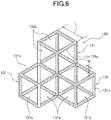
- FIG. 6 is a perspective view illustrating unit regions of a base portion according to a second embodiment.
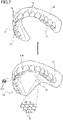
- FIG. 7 is an exploded perspective view illustrating an orthodontic aligner according to a third embodiment and the upper jaw.
- FIG. 8 is a perspective view illustrating unit regions of a base portion according to another example.
- FIG. 9A is a plan view illustrating unit regions of a base portion according to another example.
- FIG. 9B is a plan view illustrating unit regions of a base portion according to another example.
- FIG. 10A is a plan view illustrating unit regions of a base portion according to another example.
- FIG. 10B is a plan view illustrating unit regions of a base portion according to another example.
- FIG. 11A is a plan view illustrating unit regions of a base portion according to another example.
- FIG. 11B is a plan view illustrating unit regions of a base portion according to another example.
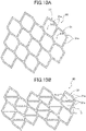
- FIG. 12 is a plan view illustrating unit regions of a base portion according to another example.
- FIG. 13 is a perspective view illustrating unit regions of a base portion according to another example.
- a dental intraoral device in the first embodiment is applied to an orthodontic aligner to be worn within an oral cavity to cover upper teeth.
- FIG. 1 is an exploded perspective view illustrating an orthodontic aligner according to the first embodiment and an upper jaw.
- FIG. 2 is a cross-sectional view illustrating a state where the orthodontic aligner according to the first embodiment is worn within an oral cavity.
- FIG. 3 is a perspective view illustrating unit regions of a base portion.
- FIG. 4 is a perspective view illustrating unit regions according to a modified example of the first embodiment.
- FIG. 5 is a perspective view illustrating unit regions according to another modified example of the first embodiment. The configuration of the orthodontic aligner according to the first embodiment is described below.
- An orthodontic aligner 20 is formed by a three-dimensional modeling device based on the three-dimensional data.
- the orthodontic aligner 20 is worn over teeth 10 before straightening, and the teeth 10 to be straightened are straightened to a desired straightening position.
- the teeth 10 are supported by gum or gingiva 15 embracing the roots of the teeth 10.
- a part that protrudes from the gingiva 15 is a tooth crown 11.
- the orthodontic aligner 20 includes crown portions 21 that are formed in a recessed groove shape to cover tooth crowns 11, and a bed or base portion 30 that connects palatal-side edges of the crown portions 21.
- the base portion 30 is formed to follow the shape of the upper jaw 16 and has a predetermined thickness H.
- the thickness H may be in a ranger from 0.05 [mm] or more to 0.8 [mm] or less.
- the thickness H may be 0.7 [mm] or less.
- the base portion 30 is formed into a mesh shape by approximately regularly arranging the unit regions 31 including holes 31b.
- the mesh shape means a regular or at least partially random three-dimensional mesh structure.
- FIG. 1 partially illustrates the unit regions 31 in an enlarged view.
- the base portion 30 is entirely formed into the mesh shape in the first embodiment. However, a part of the base portion 30 may be formed into the mesh shape.
- FIGS. 3 to 5 illustrate examples of the unit regions 31.
- each of the unit regions 31 is formed by a regular hexagon in the present embodiment.
- the regular hexagon is a regular polygon that can tessellate (realize a tessellation) with one type of the polygon (polygonal shape).
- Each of the unit regions 31 is formed in a tubular or cylindrical shape by side walls 31a, which define the regular hexagon in a plan view, and includes the hole 31b that extends in a vertical direction. The hole 31b allows saliva, heat, and the like to be transmitted to the upper jaw 16.
- a length L of each side of the unit region 31 is preferably, for example, 0.1 [mm] or more in terms of the passability of saliva, and is preferably, for example, 5.0 [mm] or less in terms of the securing of its strength.
- a thickness T of the side wall 31a may be set to a predetermined value (e.g., 0.02 [mm]).
- a ratio L/T of the thickness T to the length L is preferably 1.25 to 50, more preferably 1.5 to 40, and yet more preferably 2.0 to 30. The saliva easily passes when the ratio L/T of the thickness T to the length L is 1.25 or more.
- the side walls 31a that define the sides become difficult to buckle when the ratio L/T of the thickness T to the length L is 50 or less.
- each of the unit regions 31 in another example may be formed by a regular triangle.
- the regular triangle is a regular polygon that can tessellate (realize the tessellation) with one type of the polygon (polygonal shape).
- Each of the unit regions 31 is formed in the tubular or cylindrical shape by the side walls 31a, which define the regular triangle in a plan view, and includes the hole 31b that extends in the vertical direction. The hole 31b allows saliva, heat, and the like to be transmitted to the upper jaw 16.
- the length L of each side of the unit region 31 is preferably, for example, 0.1 [mm] or more in terms of the passability of saliva, and preferably 5.0 [mm] or less in terms of the securing of its strength.
- the thickness T of the side wall 31a may be set to a predetermined value (e.g., 0.02 [mm]).
- the ratio L/T of the thickness T to the length L is preferably 2.5 to 100, more preferably 3.0 to 90, and yet more preferably 3.5 to 80.
- the saliva easily passes when the ratio L/T of the thickness T to the length L is 2.5 or more.
- the side walls 31a that define the sides becomes difficult to buckle when the ratio L/T of the thickness T to the length L is 100 or less.
- each of the unit regions 31 in another different example may be formed by a regular tetragon.
- the regular tetragon is a regular polygon that can tessellate (realize a tessellation) with one type of the polygon.
- Each of the unit regions 31 is formed in the tubular or cylindrical shape by the side walls 31a, which define the regular tetragon in a plan view, and includes the hole 31b that extends in the vertical direction. The hole 31b allows saliva, heat, and the like to be transmitted to the upper jaw 16.
- the length L of each side of the unit region 31 is preferably, for example, 0.1 [mm] or more in terms of the passability of saliva, and preferably 5.0 [mm] or less in terms of the securing of strength.
- the thickness T of the side wall 31a may be set to a predetermined value (e.g., 0.02 [mm]).
- the ratio L/T of the thickness T to the length L is preferably 2.0 to 80, more preferably 2.5 to 70, and yet more preferably 3.0 to 60.
- the saliva easily passes when the ratio L/T of the thickness T to the length L is 2.0 or more.
- the side walls 31a that define the sides become difficult to buckle when the ratio L/T of the thickness T to the length L is 80 or less.
- the orthodontic aligner 20 is additively manufactured by applying ultraviolet laser light to a photo-curing resin by using the three-dimensional modeling device based on three-dimensional data of the orthodontic aligner 20 previously generated by three-dimensional software.
- a resin containing a radical polymerizable compound such as a meth(acrylic) monomer, a polymerizable monomer including a cationic polymerization compound such as an epoxy compound, and a photopolymerization initiator may be used as the photo-curing resin.
- the orthodontic aligner 20 as configured above is worn to cover the tooth crown 11 in the upper jaw 16.
- the teeth 10 wearing the orthodontic aligner 20 are straightened to a desired straightening position.
- a plurality of the orthodontic aligners 20 is prepared to straighten the teeth 10 to the final desired straightening position step by step.
- the cross-sectional shape of the unit region 31 is not limited to a regular hexagon, a regular triangle, or a regular tetragon, and may be a regular polygon that can tessellate (realize the tessellation) with one type of the polygon (polygonal shape). Also, the cross-sectional shape of the unit region 31 may be a regular polygon that can realize the tessellation by following the shape of the upper jaw 16.
- the dental intraoral device (orthodontic aligner 20) according to the first embodiment is a dental intraoral device that is worn within an oral cavity (upper jaw 16) including a resin base portion 30 that follows a shape of the oral cavity (upper jaw 16), wherein at least a part of the base portion 30 is formed into a mesh shape ( FIG. 1 ).
- Providing the base portion 30 makes it is possible to disperse the force applied to the dental intraoral device (orthodontic aligner) and prevent stress concentration. Further, by forming the base portion 30 in a mesh shape, the thickness of the base portion 30 can be reduced while ensuring a predetermined strength. Thereby, the dental intraoral device (orthodontic aligner 20) ensures a predetermined strength and allows the oral cavity to open relatively wider while wearing the dental intraoral device (orthodontic aligner 20). This makes it easier to pronounce and feel the temperature of food, which improves the QOL (Quality of Life) of the wearer.
- QOL Quality of Life
- the dental intraoral device (orthodontic aligner 20) can be relatively light. Thereby, the feeling of the foreign object for the patient can be reduced, and the falling off of the dental intraoral device (orthodontic aligner 20) due to its weight can be inhibited. Further, the dental intraoral device (orthodontic aligner 20) improves the passability of saliva and is therefore effective in inhibiting intraoral drying, preventing ulcers and tooth decay resulting from drying, and accelerating wound healing. Patients with weak resistance of mucous membranes relative to mechanical irritation due to diabetes or the like may suffer ulcers and pain due to damage to the tissue due to the dental intraoral device having the base portion. However, the dental intraoral device (orthodontic aligner 20) according to the present disclosure can reduce the contact area with the patient and accordingly, alleviate such symptoms.
- At least a part of the base portion 30 is formed by approximately regularly arranging the unit regions 31 having the holes 31b (bottom figure in FIG. 1 ).
- the force applied to the base portion 30 can be isotropically dispersed to prevent stress concentration. Therefore, it is possible to increase the amount of elastic deformation of the base portion 30 so as not to cause plastic deformation or fracture. As a result, the dental intraoral device (orthodontic aligner 20) can be easily attached to or detached from the oral cavity.
- the cross-sectional shape of the unit region 31 is formed by the regular polygon that can tessellate (realize the tessellation) with one type of the polygon ( FIGS. 3 to 5 ).
- the base portion 30 is provided with the unit regions 31 having uniform shapes without gaps among them. Therefore, the base portion 30 can be made thinner while ensuring a predetermined strength to make the base portion supple, hard to break, and relatively lighter.
- the length of each side of the unit region 31 is 0.1 mm or more ( FIGS. 3 to 5 ).
- a dental intraoral device differs from the dental intraoral device according to the first embodiment in that the configuration of a base portion is different from that of the base portion in the first embodiment.
- FIG. 6 is a perspective view illustrating unit regions of a base portion according to the second embodiment.
- the configuration of the dental intraoral device according to the second embodiment is described below. Note that parts that are the same as or equivalent to those that have been described in the first embodiment are described by using the same terms and the same reference signs.
- a base portion 130 according to the second embodiment is formed into a mesh shape by approximately regularly arranging unit regions 131 having holes 131b.
- Each of the unit regions 131 is formed by a regular hexahedron.
- the regular hexahedron is a polyhedron that can realize space-filling (fill a space) with one type of the polyhedron.
- the unit regions 131 are formed by the regular hexahedron that can fill a space having a predetermined thickness H along the shape of the upper jaw 16.
- Each of the unit regions 131 is formed into a frame shape by a frame 131c that connects the sides of the hexahedron and includes openings or holes 131b formed through the surfaces. The hole 31b allows saliva, heat, and the like to be transmitted to the upper jaw 16.
- the unit regions 131 fill the space having the predetermined thickness H along the shape of the upper jaw 16 to form the base portion 130.
- a length L of each side of the unit region 131 may be in a range from 0.1 [mm] or more to 5.0 [mm] or less, for example.
- a width W of the frame 131c may be set to a predetermined value (e.g., 0.02 [mm]).
- a ratio L/W of the width W to the length L is preferably 2.0 to 80, more preferably 2.5 to 70, and yet more preferably 3.0 to 60. The saliva easily passes when the ratio L/W of the width W to the length L is 2.0 or more.
- the frame 131c that defines the sides becomes difficult to buckle when the ratio L/T of the width W to the length L is 80 or less.
- each of the unit regions 131 is formed by the polyhedron that can realize the space-filling (fill the space) with one type of the polyhedron ( FIG. 6 ).
- the base portion 130 can be provided with the unit regions 131 that have uniform shapes and are arranged without gaps. Thereby, the base portion 130 can be made thinner and lighter while ensuring a predetermined strength. As a result, wearing the orthodontic aligner 20 makes it easier to pronounce and feel the temperature of food, which improves the QOL (Quality of Life) of the wearer.
- QOL Quality of Life
- a dental intraoral device differs from the dental intraoral device according to the first embodiment in that the configuration of a base portion is different from that of the base portion in the first embodiment.
- FIG. 7 is an exploded perspective view illustrating an orthodontic aligner according to the third embodiment and an upper jaw.
- the configuration of the dental intraoral device according to the third embodiment is described below. Note that parts that are the same as or equivalent to ones that have been described in the first and second embodiments are described by using the same terms or the same reference signs.
- a front part 230 of the base portion 30 is formed by the unit regions 231 having higher rigidity than the unit regions 31 of the other parts of the base portion 30.
- the front part 230 is a front-side portion of the base portion 30 of the orthodontic aligner 20 attached to the upper jaw 16, that is a part of the base portion 30 close to the anterior teeth (front teeth) 12.
- the front part 230 is a part of the base portion 30 close to the crown portions 21 covering the anterior teeth 12.
- FIG. 7 illustrates parts of the unit regions 31, 231 in an enlarged view.
- the unit regions 231 of the front part 230 may be formed with smaller shapes than the unit regions 31 of the other parts to have higher rigidity than the unit regions 31. More specifically, the length of each side of each unit region 231 of the front part 230 may be set to 0.1 [mm] while the length of each side of each unit region 31 of the other parts may be set to 0.5 [mm], for example.
- each side wall of the unit region 231 of the front part 230 may be made thicker than that of each side wall of the unit region 31 of the other parts so that the rigidity of the unit region 231 becomes higher than that of the unit region 31.
- the dental intraoral device orthodontic aligner 20
- the front part 230 of the base portion 30 is formed by the unit regions 231 having higher rigidity than the unit regions 31 of the other parts of the base portion 30 ( FIG. 7 ).
- the unit regions 231 in the front part 230 of the base portion 30 having higher rigidity than the unit regions 31 of the other parts of the base portion 30, for example, it is possible to increase the strength of the front part 230 to which larger stress is applied when attaching and detaching the dental intraoral device (orthodontic aligner 20).
- the unit regions 231 of the front part 230 of the base portion 30 having a denser configuration than the unit regions 31 of the other parts of the base portion 30, it is possible to increase the strength of the front part 230 to which the larger stress is applied when attaching and detaching the dental intraoral device (orthodontic aligner 20).
- wearing the orthodontic aligner 20 according to the third embodiment makes it easier to pronounce and feel the temperature of food, which improves the QOL (Quality of Life) of the wearer.
- the stereolithography apparatus using the photo-curing resin that is cured by ultraviolet laser light has been shown.
- the three-dimensional modeling device may be a projection type that cures and laminates a photo-curing resin by utilizing the light of a projector, may be an inkjet type that cures and laminates a liquid photo-curing resin by jetting the resin and applying ultraviolet light thereto, may be a fused deposition modeling type that piles up a thermoplastic resin layer by layer, or may be a powder sintering type that applies high-output laser light to a powder material and sinters the material.
- the base portion 30 is formed by one layer or stage of the unit regions.
- the base portion 30 may be formed by two layers or stages of the unit regions as illustrated in FIG. 8 or may be formed by three or more layers or stages of the unit regions.
- the cross-sectional shape of the unit region 31 is the regular polygon that can tessellate (realize the tessellation) with one type of the polygon (polygonal shape).
- the cross-sectional shape of the unit region may be a polygon that can tessellate with one type of the polygon (polygonal shape).
- the polygon that can tessellate (realize the tessellation) with one type of the polygon may be a parallelogram as illustrated in FIG. 9A .
- the polygon that can tessellate with one type of the polygon may be a parallelogram that is formed by combining two congruent triangles as illustrated in FIG. 9B .
- the polygon that can tessellate with one type of the polygon may be a parallel hexagon as illustrated in FIG. 10A .
- the polygon that can tessellate with one type of the polygon may be a parallel hexagon formed by combining two congruent quadrangles as illustrated in FIG. 10B .
- the polygon that can tessellate with one type of the polygon may be a parallel hexagon formed by combining two congruent pentagons as illustrated in FIG. 11A .
- the polygon that can tessellate with one type of the polygon may be a pentagon that can tessellate as illustrated in FIG. 11B .
- a polygon that can tessellate (realize the tessellation) with two or more types of polygons may be a regular polygon that is an Archimedes' tessellation shape.
- the polygon that can tessellate with two or more types of polygons may be a shape formed by eight regular triangles and one regular hexagon, as illustrated in FIG. 12 .
- a polygon that can tessellate (realize the tessellation) preferably a combination of one or more of a triangle, a quadrangle, a pentagon, a regular polygon, and a parallel hexagon.
- the polygon that can tessellate may be more preferably a combination of one or more of the regular polygon, the parallelogram, and the parallel hexagon.
- the polygon that can tessellate may be yet more preferably a combination of one or more of the regular triangle, the regular tetragon, and the regular hexagon.
- the cross-sectional shape of the unit region may be formed by a regular polygon that can tessellate (realize the tessellation), may be formed by a polygon that can tessellate, or may be formed by a figure that can tessellate.
- the unit region 131 is the regular hexagon (Archimedes' regular quadratic prism) that can realize the space-filling (fill the space) with one type of the polyhedron.
- the unit region may be a uniform polyhedron that can realize the space-filling with one type of the polyhedron.
- the uniform polyhedron that can realize the space-filling (fill the space) with one type of the polyhedron may be, for example, an Archimedes' regular triangular prism, Archimedes' regular hexagonal prism, a truncated octahedron, a rhombic dodecahedron, or the like.
- the unit region may be a polyhedron that can realize the space-filling (fill the space) with one type of the polyhedron.
- the polyhedron that can realize the space-filling with one type of the polyhedron may be, for example, a gyrobifastigium (Johnson solid J26) or the like.
- the unit region may be a uniform polyhedron that can realize the space-filling (fill the space) by two or more types of the polyhedron.
- the uniform polyhedron that can realize the space-filling by two or more types of the polyhedron may be, for example, a uniform polyhedron that consists of a regular tetrahedron and a regular octahedron, a uniform polyhedron that consists of a regular tetrahedron and a truncated tetrahedron, a uniform polyhedron that consists of a regular octahedron and a truncated hexahedron, a uniform polyhedron that consists of a regular octahedron and a cuboctahedron, or a uniform polyhedron that consists of a rhombitruncated cuboctahedron and a regular octagonal prism.
- the uniform polyhedron that can realize the space-filling (fill the space) by two or more types of the polyhedron may be, for example, a uniform polyhedron that consists of a truncated tetrahedron, a truncated octahedron, and a cuboctahedron, a uniform polyhedron that consists of a truncated tetrahedron, a truncated hexahedron, and a rhombitruncated cuboctahedron, a uniform polyhedron that consists of a regular tetrahedron, a cube, and a rhombicuboctahedron, a uniform polyhedron that consists of a cube, a cuboctahedron, and a rhombicuboctahedron, or a uniform polyhedron that consists of a cube, a truncated octahedron, and a rhom
- a uniform polyhedron that can realize the space-filling (fill the space) by two or more types of the polyhedron may be, for example, a combination of a cube, a truncated hexahedron, a rhombitruncated cub octahedron, and a regular octagonal prism, or a combination of various types of equilateral rhombic polyhedrons.
- the unit region may be a polyhedron that can realize the space-filling (fill the space) by two or more types of the polyhedron.
- the polyhedron that can realize the space-filling by two or more types of the polyhedron may be, for example, a polyhedron that consists of Johnson solid J1 (square pyramid) and Johnson solid J3 (triangular cupola), a polyhedron that consists of Johnson solid J1 (square pyramid) and Johnson solid J7 (elongated triangular pyramid), a polyhedron that consists of Johnson solid J1 and Johnson solid J27 (triangular orthobicupola), a polyhedron that consists of a regular tetrahedron and Johnson solid J1, a polyhedron that consists of a regular tetrahedron and Johnson solid J4 (square cupola), a polyhedron that consists of a regular tetrahedron and Johnson solid J8 (elongated square pyramid), a polyhedron that consists of a regular tetrahedron and
- the polyhedron that can realize the space-filling (fill the space) by two or more types of the polyhedron may be, for example, a polyhedron that consists of a regular tetrahedron, Johnson solid J1, and Johnson solid J18 (elongated triangular cupola), a polyhedron that consists of a regular tetrahedron, Johnson solid J1, and Johnson solid J35 (elongated triangular orthobicupola), a polyhedron that consists of a regular tetrahedron, Johnson solid J1, and Johnson solid J36 (elongated triangular gyrobicupola), a polyhedron that consists of a regular tetrahedron, Johnson solid J1, and Johnson solid J15 (elongated square bipyramid), a polyhedron that consists of a regular tetrahedron, a regular hexahedron, and Johnson solid J28, a polyhedron that consists of a regular tetrahedron, a regular t
- the polyhedron that can realize the space-filling (fill the space) by two or more types of the polyhedron may be, for example, a polyhedron that consists of one or a combination of a regular tetrahedron, a regular hexahedron, and a cuboctahedron [Johnson solid J28 and Johnson solid J29 (square gyrobicupola)], a polyhedron that consists of one or a combination of a regular tetrahedron and Johnson solid J1 [a regular hexahedron, Johnson solid J8, and Johnson solid J15] and one or a combination of [Johnson solid J28 and Johnson solid J29], a polyhedron that consists of a regular tetrahedron, a regular hexahedron, a cuboctahedron, and Johnson solid J37 (elongated square gyrobicupola), a polyhedron that consists of a regular tetrahedron, a regular hexahedron,
- the polyhedron that can realize the space-filling may be preferably a combination of one or more of a regular polyhedron, a semi-regular polyhedron, a regular prism, a regular antiprism, and a Johnson solid.
- the polyhedron that can realize the space-filling may be more preferably a combination of one or more of equilateral rhombic polyhedrons such as a regular polyhedron, a cuboctahedron, a regular polygonal prism, and a rhombic dodecahedron, a parallelepiped, a truncated octahedron, a parallelohedron such as an elongated rhombic dodecahedron, a rhombicuboctahedron, and a rhombitruncated cuboctahedron.
- equilateral rhombic polyhedrons such as a regular polyhedron, a cuboctahedron, a regular polygonal prism, and a rhombic dodecahedron
- a parallelepiped such as an elongated rhombic dodecahedron, a rhombicuboctahedron, and a rhombitruncated cu
- the polyhedron that can realize the space-filling may be yet more preferably a combination of one or more of a regular tetrahedron, a regular hexahedron (cube), a regular octahedron, a regular triangular prism, a regular quadrangular prism (cuboid), a regular hexagonal prism, a truncated octahedron, a rhombic dodecahedron, and an elongated rhombic dodecahedron.
- the improvement of the symmetry of the unit region makes it difficult for a given load to concentrate and makes it difficult for plastic deformation and breakage to be caused.
- a regular tetrahedron a regular hexahedron (cube), a regular octahedron, a regular triangular prism, a regular quadrangular prism (cuboid), a regular hexagonal prism, a truncated octahedron, a rhombic dodecahedron, and an elongated rhombic dodecahedron
- a given load is isotropically distributed, and thus plastic deformation and breakage are significantly inhibited.
- the unit region may be formed by a uniform polyhedron that can realize the space-filling (fill the space), may be formed by a polyhedron that can realize the space-filling, or may be formed by a solid that can realize the space-filling.
- the base portion 30 is entirely formed into the mesh shape by approximately regularly arranging the unit regions 31, 131 having the holes 31b, 131b.
- the base portion may be partially formed into the mesh shape by approximately regularly arranging the unit regions having the holes.
- the shape of the hole is not particularly limited but is preferably highly symmetrical.
- the cross-sectional shape of the hole may be a circle, a regular triangle, a regular tetragon, a regular pentagon, a regular hexagon, or any other regular polygon.
- the cross-sectional shape of the hole is more preferably a circle, a regular triangle, a regular tetragon, or a regular hexagon.
- the cross-sectional shape of the hole is yet more preferably a circle since the circle has no notch that may be an origin of breaking is formed.
- the sides that define each unit region are straight lines.
- the sides that define each unit region may be curved lines as long as the effects of the present disclosure are not maintained.
- a curvature radius R is preferably equal to or more than 0.3 times the length L of the side of the unit region, more preferably equal to or more than 0.5 times, and yet more preferably equal to or more than 1.0 times.
- the upper limit of the curvature radius R is not particularly limited but may be, for example, equal to or less than 100 times the length L of the side of the unit region.
- the side walls are solid.
- a part of the side wall may have a hole.
- the shape of the hole is preferably highly symmetrical.
- the cross-sectional shape of the hole may be a circle, a regular triangle, a regular tetragon, a regular pentagon, a regular hexagon, or any other regular polygon.
- the cross-sectional shape of the hole is more preferably a circle, a regular triangle, a regular tetragon, or a regular hexagon.
- the cross-sectional shape of the hole is yet more preferably a circle since the circle has no notch that may be an origin of breaking is formed.
- a reinforcing structure is not provided between side walls.
- a reinforcing structure such as braces 35 may be provided between the side walls 31a.
- the base portion 30 covers all of the gingiva, the hard palate, and the soft palate.
- the base portion may cover the gingiva and the hard palate or may cover only the gingiva.
- the base portion may cover any one or more of the gingiva, the hard palate, and the soft palate.
- the dental intraoral device according to the present disclosure is applied to the orthodontic aligner 20 to be worn within the oral cavity to cover the teeth 10 of the upper jaw 16.
- the dental intraoral device according to the present disclosure may also be applied to an orthodontic aligner to be worn within the oral cavity to cover lower-jaw teeth.
- the dental intraoral device according to the present disclosure is applied to the orthodontic aligner.
- the dental intraoral device according to the present disclosure is not limited to the orthodontic aligner and may be applied to a device or the like to be worn to cover teeth, such as an orthodontic retainer, a dental intraoral device for gnashing prevention, an oral appliance for the treatment of sleep apnea syndrome, a dental intraoral device for whitening, a mouth guard for sports, and a denture device (a complete denture, a partial denture).
- the thickness of the base portion may be in a range from 0.05 [mm] or more to 2.0 [mm] or less.
- the thickness of the base portion may be preferably 1.0 [mm] or less, more preferably 0.8 [mm] or less, and yet more preferably 0.7 [mm] or less.
- the denture base particularly the partial base
- the clasp portion may be in the shape of a hook shape, a cylinder shape, or the like.
Landscapes
- Health & Medical Sciences (AREA)
- Oral & Maxillofacial Surgery (AREA)
- Life Sciences & Earth Sciences (AREA)
- Animal Behavior & Ethology (AREA)
- General Health & Medical Sciences (AREA)
- Public Health (AREA)
- Veterinary Medicine (AREA)
- Dentistry (AREA)
- Epidemiology (AREA)
- Pulmonology (AREA)
- Otolaryngology (AREA)
- Nursing (AREA)
- Orthopedic Medicine & Surgery (AREA)
- Engineering & Computer Science (AREA)
- Biomedical Technology (AREA)
- Heart & Thoracic Surgery (AREA)
- Vascular Medicine (AREA)
- Dental Tools And Instruments Or Auxiliary Dental Instruments (AREA)
- Dental Prosthetics (AREA)
- Orthopedics, Nursing, And Contraception (AREA)
Abstract
Description
- The present disclosure relates to a dental intraoral device to be worn within an oral cavity, and a method for manufacturing the dental intraoral device.
- A mouthpiece-type intraoral device such as an orthodontic aligner and an oral appliance (OA) for the treatment of sleep apnea syndrome is formed by pressing a resin sheet into a dental model. Also, an intraoral device such as a denture base is usually formed by mixing a polymer powder such as PMMA with a monomer solution such as MMA and then heat-curing the mixture. Intraoral devices provided with a base or bed portion are known to improve the strength and fracture resistance of the intraoral devices (see Patent Literatures 1 and 2).
- Patent Literature 1 discloses a denture including a denture base and artificial teeth arranged on the denture base.
Patent Literature 2 discloses a mandibular advancement device for the treatment of snoring and/or obstructive sleep apnea. The mandibular advancement device includes a base with a shape covering a gingiva or gum. -
- Patent Literature 1:
JP 2019-130286 A - Patent Literature 2:
WO 2000/001317 A1 - However, the denture base disclosed in Patent Literature 1 as well as the mandibular advancement device for the treatment of snoring and/or obstructive sleep apnea disclosed in
Patent Literature 2 are molded into a solid shape and as a result, the base portion becomes relatively thick to ensure sufficient strength and fracture resistance. - Accordingly, an object of the present disclosure is to provide a dental intraoral device that can reduce the thickness of a base portion while having sufficient strength and fracture resistance.
- To achieve the above object, a dental intraoral device according to the present disclosure is a dental intraoral device that is worn within an oral cavity including a resin base portion that follows a shape of the oral cavity. At least a part of the base portion is formed into a mesh shape.
- The dental intraoral device of the present disclosure having such a configuration can reduce the thickness of the base portion while having sufficient strength and fracture resistance.
-
FIG. 1 is an exploded perspective view illustrating an orthodontic aligner according to a first embodiment and an upper jaw.FIG. 2 is a cross-sectional view illustrating a state where the orthodontic aligner according to the first embodiment is worn within an oral cavity.FIG. 3 is a perspective view illustrating unit regions of a base portion.FIG. 4 is a perspective view illustrating unit regions according to a modified example of the first embodiment.FIG. 5 is a perspective view illustrating unit regions according to another modified example of the first embodiment.FIG. 6 is a perspective view illustrating unit regions of a base portion according to a second embodiment.FIG. 7 is an exploded perspective view illustrating an orthodontic aligner according to a third embodiment and the upper jaw.FIG. 8 is a perspective view illustrating unit regions of a base portion according to another example.FIG. 9A is a plan view illustrating unit regions of a base portion according to another example.FIG. 9B is a plan view illustrating unit regions of a base portion according to another example.FIG. 10A is a plan view illustrating unit regions of a base portion according to another example.FIG. 10B is a plan view illustrating unit regions of a base portion according to another example.FIG. 11A is a plan view illustrating unit regions of a base portion according to another example.FIG. 11B is a plan view illustrating unit regions of a base portion according to another example.FIG. 12 is a plan view illustrating unit regions of a base portion according to another example.FIG. 13 is a perspective view illustrating unit regions of a base portion according to another example. - Hereinafter, embodiments of a dental intraoral device according to the present disclosure are described with reference to first to third embodiments illustrated in the drawings.
- A dental intraoral device in the first embodiment is applied to an orthodontic aligner to be worn within an oral cavity to cover upper teeth.
- (Configuration of Orthodontic Aligner)
FIG. 1 is an exploded perspective view illustrating an orthodontic aligner according to the first embodiment and an upper jaw.FIG. 2 is a cross-sectional view illustrating a state where the orthodontic aligner according to the first embodiment is worn within an oral cavity.FIG. 3 is a perspective view illustrating unit regions of a base portion.FIG. 4 is a perspective view illustrating unit regions according to a modified example of the first embodiment.FIG. 5 is a perspective view illustrating unit regions according to another modified example of the first embodiment. The configuration of the orthodontic aligner according to the first embodiment is described below. - An
orthodontic aligner 20 is formed by a three-dimensional modeling device based on the three-dimensional data. Theorthodontic aligner 20 is worn overteeth 10 before straightening, and theteeth 10 to be straightened are straightened to a desired straightening position. - As illustrated in the upper drawing in
FIG. 1 , theteeth 10 are supported by gum orgingiva 15 embracing the roots of theteeth 10. A part that protrudes from thegingiva 15 is atooth crown 11. - As illustrated in the lower drawing in
FIG. 1 andFIG. 2 , theorthodontic aligner 20 includescrown portions 21 that are formed in a recessed groove shape to covertooth crowns 11, and a bed orbase portion 30 that connects palatal-side edges of thecrown portions 21. Thebase portion 30 is formed to follow the shape of theupper jaw 16 and has a predetermined thickness H. The thickness H may be in a ranger from 0.05 [mm] or more to 0.8 [mm] or less. Preferably, the thickness H may be 0.7 [mm] or less. - As illustrated in
FIGS. 1 and3 , thebase portion 30 is formed into a mesh shape by approximately regularly arranging theunit regions 31 includingholes 31b. The mesh shape means a regular or at least partially random three-dimensional mesh structure. Note thatFIG. 1 partially illustrates theunit regions 31 in an enlarged view. Thebase portion 30 is entirely formed into the mesh shape in the first embodiment. However, a part of thebase portion 30 may be formed into the mesh shape.FIGS. 3 to 5 illustrate examples of theunit regions 31. - (Regular Hexagon Unit Region) As illustrated in
FIG. 3 , the cross-sectional shape of each of theunit regions 31 is formed by a regular hexagon in the present embodiment. The regular hexagon is a regular polygon that can tessellate (realize a tessellation) with one type of the polygon (polygonal shape). Each of theunit regions 31 is formed in a tubular or cylindrical shape byside walls 31a, which define the regular hexagon in a plan view, and includes thehole 31b that extends in a vertical direction. Thehole 31b allows saliva, heat, and the like to be transmitted to theupper jaw 16. - A length L of each side of the
unit region 31 is preferably, for example, 0.1 [mm] or more in terms of the passability of saliva, and is preferably, for example, 5.0 [mm] or less in terms of the securing of its strength. A thickness T of theside wall 31a may be set to a predetermined value (e.g., 0.02 [mm]). A ratio L/T of the thickness T to the length L is preferably 1.25 to 50, more preferably 1.5 to 40, and yet more preferably 2.0 to 30. The saliva easily passes when the ratio L/T of the thickness T to the length L is 1.25 or more. Theside walls 31a that define the sides become difficult to buckle when the ratio L/T of the thickness T to the length L is 50 or less. - (Regular Triangle Unit Region) As illustrated in
FIG. 4 , the cross-sectional shape of each of theunit regions 31 in another example may be formed by a regular triangle. The regular triangle is a regular polygon that can tessellate (realize the tessellation) with one type of the polygon (polygonal shape). Each of theunit regions 31 is formed in the tubular or cylindrical shape by theside walls 31a, which define the regular triangle in a plan view, and includes thehole 31b that extends in the vertical direction. Thehole 31b allows saliva, heat, and the like to be transmitted to theupper jaw 16. - The length L of each side of the
unit region 31 is preferably, for example, 0.1 [mm] or more in terms of the passability of saliva, and preferably 5.0 [mm] or less in terms of the securing of its strength. The thickness T of theside wall 31a may be set to a predetermined value (e.g., 0.02 [mm]). The ratio L/T of the thickness T to the length L is preferably 2.5 to 100, more preferably 3.0 to 90, and yet more preferably 3.5 to 80. The saliva easily passes when the ratio L/T of the thickness T to the length L is 2.5 or more. Theside walls 31a that define the sides becomes difficult to buckle when the ratio L/T of the thickness T to the length L is 100 or less. - (Regular Tetragon Unit Region) As illustrated in
FIG. 5 , the cross-sectional shape of each of theunit regions 31 in another different example may be formed by a regular tetragon. The regular tetragon is a regular polygon that can tessellate (realize a tessellation) with one type of the polygon. Each of theunit regions 31 is formed in the tubular or cylindrical shape by theside walls 31a, which define the regular tetragon in a plan view, and includes thehole 31b that extends in the vertical direction. Thehole 31b allows saliva, heat, and the like to be transmitted to theupper jaw 16. - The length L of each side of the
unit region 31 is preferably, for example, 0.1 [mm] or more in terms of the passability of saliva, and preferably 5.0 [mm] or less in terms of the securing of strength. The thickness T of theside wall 31a may be set to a predetermined value (e.g., 0.02 [mm]). The ratio L/T of the thickness T to the length L is preferably 2.0 to 80, more preferably 2.5 to 70, and yet more preferably 3.0 to 60. The saliva easily passes when the ratio L/T of the thickness T to the length L is 2.0 or more. Theside walls 31a that define the sides become difficult to buckle when the ratio L/T of the thickness T to the length L is 80 or less. - The
orthodontic aligner 20 is additively manufactured by applying ultraviolet laser light to a photo-curing resin by using the three-dimensional modeling device based on three-dimensional data of theorthodontic aligner 20 previously generated by three-dimensional software. For example, a resin containing a radical polymerizable compound such as a meth(acrylic) monomer, a polymerizable monomer including a cationic polymerization compound such as an epoxy compound, and a photopolymerization initiator may be used as the photo-curing resin. - As illustrated in
FIG. 2 , theorthodontic aligner 20 as configured above is worn to cover thetooth crown 11 in theupper jaw 16. Theteeth 10 wearing theorthodontic aligner 20 are straightened to a desired straightening position. - A plurality of the
orthodontic aligners 20 is prepared to straighten theteeth 10 to the final desired straightening position step by step. - Note that the cross-sectional shape of the
unit region 31 is not limited to a regular hexagon, a regular triangle, or a regular tetragon, and may be a regular polygon that can tessellate (realize the tessellation) with one type of the polygon (polygonal shape). Also, the cross-sectional shape of theunit region 31 may be a regular polygon that can realize the tessellation by following the shape of theupper jaw 16. - (Effect of Dental Intraoral Device) The effect of the dental intraoral device (orthodontic aligner 20) according to the first embodiment is described below. The dental intraoral device (orthodontic aligner 20) according to the first embodiment is a dental intraoral device that is worn within an oral cavity (upper jaw 16) including a
resin base portion 30 that follows a shape of the oral cavity (upper jaw 16), wherein at least a part of thebase portion 30 is formed into a mesh shape (FIG. 1 ). - Providing the
base portion 30 makes it is possible to disperse the force applied to the dental intraoral device (orthodontic aligner) and prevent stress concentration. Further, by forming thebase portion 30 in a mesh shape, the thickness of thebase portion 30 can be reduced while ensuring a predetermined strength. Thereby, the dental intraoral device (orthodontic aligner 20) ensures a predetermined strength and allows the oral cavity to open relatively wider while wearing the dental intraoral device (orthodontic aligner 20). This makes it easier to pronounce and feel the temperature of food, which improves the QOL (Quality of Life) of the wearer. - In addition, the dental intraoral device (orthodontic aligner 20) can be relatively light. Thereby, the feeling of the foreign object for the patient can be reduced, and the falling off of the dental intraoral device (orthodontic aligner 20) due to its weight can be inhibited. Further, the dental intraoral device (orthodontic aligner 20) improves the passability of saliva and is therefore effective in inhibiting intraoral drying, preventing ulcers and tooth decay resulting from drying, and accelerating wound healing. Patients with weak resistance of mucous membranes relative to mechanical irritation due to diabetes or the like may suffer ulcers and pain due to damage to the tissue due to the dental intraoral device having the base portion. However, the dental intraoral device (orthodontic aligner 20) according to the present disclosure can reduce the contact area with the patient and accordingly, alleviate such symptoms.
- In the dental intraoral device (orthodontic aligner 20) according to the first embodiment, at least a part of the
base portion 30 is formed by approximately regularly arranging theunit regions 31 having theholes 31b (bottom figure inFIG. 1 ). - Thereby, the force applied to the
base portion 30 can be isotropically dispersed to prevent stress concentration. Therefore, it is possible to increase the amount of elastic deformation of thebase portion 30 so as not to cause plastic deformation or fracture. As a result, the dental intraoral device (orthodontic aligner 20) can be easily attached to or detached from the oral cavity. - In the dental intraoral device (orthodontic aligner 20) according to the first embodiment, the cross-sectional shape of the
unit region 31 is formed by the regular polygon that can tessellate (realize the tessellation) with one type of the polygon (FIGS. 3 to 5 ). - Thereby, the
base portion 30 is provided with theunit regions 31 having uniform shapes without gaps among them. Therefore, thebase portion 30 can be made thinner while ensuring a predetermined strength to make the base portion supple, hard to break, and relatively lighter. - In the dental intraoral device (orthodontic aligner 20) according to the first embodiment, the length of each side of the
unit region 31 is 0.1 mm or more (FIGS. 3 to 5 ). - This can make it easier for a resin to flow out from the
holes 31b of theunit regions 31, and avoid resin retention or the like when the dental intraoral device (orthodontic aligner 20) is manufactured by the three-dimensional modeling device. - A dental intraoral device according to a second embodiment differs from the dental intraoral device according to the first embodiment in that the configuration of a base portion is different from that of the base portion in the first embodiment.
- (Configuration of Dental Intraoral Device)
FIG. 6 is a perspective view illustrating unit regions of a base portion according to the second embodiment. The configuration of the dental intraoral device according to the second embodiment is described below. Note that parts that are the same as or equivalent to those that have been described in the first embodiment are described by using the same terms and the same reference signs. - As illustrated in
FIG. 6 , abase portion 130 according to the second embodiment is formed into a mesh shape by approximately regularly arrangingunit regions 131 havingholes 131b. - Each of the
unit regions 131 is formed by a regular hexahedron. The regular hexahedron is a polyhedron that can realize space-filling (fill a space) with one type of the polyhedron. In other words, theunit regions 131 are formed by the regular hexahedron that can fill a space having a predetermined thickness H along the shape of theupper jaw 16. Each of theunit regions 131 is formed into a frame shape by aframe 131c that connects the sides of the hexahedron and includes openings orholes 131b formed through the surfaces. Thehole 31b allows saliva, heat, and the like to be transmitted to theupper jaw 16. - The
unit regions 131 fill the space having the predetermined thickness H along the shape of theupper jaw 16 to form thebase portion 130. - A length L of each side of the
unit region 131 may be in a range from 0.1 [mm] or more to 5.0 [mm] or less, for example. A width W of theframe 131c may be set to a predetermined value (e.g., 0.02 [mm]). A ratio L/W of the width W to the length L is preferably 2.0 to 80, more preferably 2.5 to 70, and yet more preferably 3.0 to 60. The saliva easily passes when the ratio L/W of the width W to the length L is 2.0 or more. Theframe 131c that defines the sides becomes difficult to buckle when the ratio L/T of the width W to the length L is 80 or less. - (Effect of Dental Intraoral Device) The effect of the dental intraoral device (orthodontic aligner 20) according to the second embodiment is described below. In the dental intraoral device (orthodontic aligner 20) according to the second embodiment, each of the
unit regions 131 is formed by the polyhedron that can realize the space-filling (fill the space) with one type of the polyhedron (FIG. 6 ). - Thus, the
base portion 130 can be provided with theunit regions 131 that have uniform shapes and are arranged without gaps. Thereby, thebase portion 130 can be made thinner and lighter while ensuring a predetermined strength. As a result, wearing theorthodontic aligner 20 makes it easier to pronounce and feel the temperature of food, which improves the QOL (Quality of Life) of the wearer. - Note that other configurations and advantageous effects are approximately similar to those in the first embodiment described above, and the descriptions thereof are omitted.
- A dental intraoral device according to a third embodiment differs from the dental intraoral device according to the first embodiment in that the configuration of a base portion is different from that of the base portion in the first embodiment.
- (Configuration of Dental Intraoral Device)
FIG. 7 is an exploded perspective view illustrating an orthodontic aligner according to the third embodiment and an upper jaw. The configuration of the dental intraoral device according to the third embodiment is described below. Note that parts that are the same as or equivalent to ones that have been described in the first and second embodiments are described by using the same terms or the same reference signs. - As illustrated in
FIG. 7 , afront part 230 of thebase portion 30 is formed by theunit regions 231 having higher rigidity than theunit regions 31 of the other parts of thebase portion 30. Thefront part 230 is a front-side portion of thebase portion 30 of theorthodontic aligner 20 attached to theupper jaw 16, that is a part of thebase portion 30 close to the anterior teeth (front teeth) 12. In other words, thefront part 230 is a part of thebase portion 30 close to thecrown portions 21 covering theanterior teeth 12. Note thatFIG. 7 illustrates parts of theunit regions - For example, the
unit regions 231 of thefront part 230 may be formed with smaller shapes than theunit regions 31 of the other parts to have higher rigidity than theunit regions 31. More specifically, the length of each side of eachunit region 231 of thefront part 230 may be set to 0.1 [mm] while the length of each side of eachunit region 31 of the other parts may be set to 0.5 [mm], for example. - Also, the thickness of each side wall of the
unit region 231 of thefront part 230 may be made thicker than that of each side wall of theunit region 31 of the other parts so that the rigidity of theunit region 231 becomes higher than that of theunit region 31. - (Effect of Dental Intraoral Device) The effect of the dental intraoral device (orthodontic aligner 20) according to the third embodiment is described below. In the
orthodontic aligner 20 according to the third embodiment, thefront part 230 of thebase portion 30 is formed by theunit regions 231 having higher rigidity than theunit regions 31 of the other parts of the base portion 30 (FIG. 7 ). - By forming the
unit regions 231 in thefront part 230 of thebase portion 30 having higher rigidity than theunit regions 31 of the other parts of thebase portion 30, for example, it is possible to increase the strength of thefront part 230 to which larger stress is applied when attaching and detaching the dental intraoral device (orthodontic aligner 20). - For example, by forming the
unit regions 231 of thefront part 230 of thebase portion 30 having a denser configuration than theunit regions 31 of the other parts of thebase portion 30, it is possible to increase the strength of thefront part 230 to which the larger stress is applied when attaching and detaching the dental intraoral device (orthodontic aligner 20). As a result, wearing theorthodontic aligner 20 according to the third embodiment makes it easier to pronounce and feel the temperature of food, which improves the QOL (Quality of Life) of the wearer. - Note that other configurations and advantageous effects are approximately similar to those in the first and second embodiments described above, and accordingly, the description thereof is omitted.
- The dental intraoral device according to the present disclosure has been described above in accordance with the first to third embodiments. However, the specific configurations are not limited to the ones described in these embodiments, and design changes, additions, combinations of the embodiments, and the like are allowed without departing from the spirit of the invention according to each claim.
- In the first to third embodiments, as an example of the three-dimensional modeling device, the stereolithography apparatus using the photo-curing resin that is cured by ultraviolet laser light has been shown. However, the three-dimensional modeling device may be a projection type that cures and laminates a photo-curing resin by utilizing the light of a projector, may be an inkjet type that cures and laminates a liquid photo-curing resin by jetting the resin and applying ultraviolet light thereto, may be a fused deposition modeling type that piles up a thermoplastic resin layer by layer, or may be a powder sintering type that applies high-output laser light to a powder material and sinters the material.
- In the first and third embodiments, the
base portion 30 is formed by one layer or stage of the unit regions. However, thebase portion 30 may be formed by two layers or stages of the unit regions as illustrated inFIG. 8 or may be formed by three or more layers or stages of the unit regions. - In the first and third embodiments, the cross-sectional shape of the
unit region 31 is the regular polygon that can tessellate (realize the tessellation) with one type of the polygon (polygonal shape). However, the cross-sectional shape of the unit region may be a polygon that can tessellate with one type of the polygon (polygonal shape). - For example, the polygon that can tessellate (realize the tessellation) with one type of the polygon may be a parallelogram as illustrated in
FIG. 9A . Alternatively, the polygon that can tessellate with one type of the polygon may be a parallelogram that is formed by combining two congruent triangles as illustrated inFIG. 9B . Alternatively, the polygon that can tessellate with one type of the polygon may be a parallel hexagon as illustrated inFIG. 10A . Alternatively, the polygon that can tessellate with one type of the polygon may be a parallel hexagon formed by combining two congruent quadrangles as illustrated inFIG. 10B . Alternatively, the polygon that can tessellate with one type of the polygon may be a parallel hexagon formed by combining two congruent pentagons as illustrated inFIG. 11A . Alternatively, the polygon that can tessellate with one type of the polygon may be a pentagon that can tessellate as illustrated inFIG. 11B . - Moreover, a polygon that can tessellate (realize the tessellation) with two or more types of polygons may be a regular polygon that is an Archimedes' tessellation shape. For example, the polygon that can tessellate with two or more types of polygons may be a shape formed by eight regular triangles and one regular hexagon, as illustrated in
FIG. 12 . - A polygon that can tessellate (realize the tessellation) preferably a combination of one or more of a triangle, a quadrangle, a pentagon, a regular polygon, and a parallel hexagon. The polygon that can tessellate may be more preferably a combination of one or more of the regular polygon, the parallelogram, and the parallel hexagon. The polygon that can tessellate may be yet more preferably a combination of one or more of the regular triangle, the regular tetragon, and the regular hexagon. The improvement of the symmetry of the unit region makes it difficult for a given load to concentrate and makes it difficult for plastic deformation and breakage to be caused. Particularly, in the regular triangle, the regular tetragon, and the regular hexagon, a given load is isotropically distributed, and thus plastic deformation and breakage are significantly inhibited.
- In other words, the cross-sectional shape of the unit region may be formed by a regular polygon that can tessellate (realize the tessellation), may be formed by a polygon that can tessellate, or may be formed by a figure that can tessellate.
- In the second embodiment, the
unit region 131 is the regular hexagon (Archimedes' regular quadratic prism) that can realize the space-filling (fill the space) with one type of the polyhedron. However, the unit region may be a uniform polyhedron that can realize the space-filling with one type of the polyhedron. - The uniform polyhedron that can realize the space-filling (fill the space) with one type of the polyhedron may be, for example, an Archimedes' regular triangular prism, Archimedes' regular hexagonal prism, a truncated octahedron, a rhombic dodecahedron, or the like.
- The unit region may be a polyhedron that can realize the space-filling (fill the space) with one type of the polyhedron. The polyhedron that can realize the space-filling with one type of the polyhedron may be, for example, a gyrobifastigium (Johnson solid J26) or the like.
- The unit region may be a uniform polyhedron that can realize the space-filling (fill the space) by two or more types of the polyhedron. The uniform polyhedron that can realize the space-filling by two or more types of the polyhedron may be, for example, a uniform polyhedron that consists of a regular tetrahedron and a regular octahedron, a uniform polyhedron that consists of a regular tetrahedron and a truncated tetrahedron, a uniform polyhedron that consists of a regular octahedron and a truncated hexahedron, a uniform polyhedron that consists of a regular octahedron and a cuboctahedron, or a uniform polyhedron that consists of a rhombitruncated cuboctahedron and a regular octagonal prism.
- Alternatively, the uniform polyhedron that can realize the space-filling (fill the space) by two or more types of the polyhedron may be, for example, a uniform polyhedron that consists of a truncated tetrahedron, a truncated octahedron, and a cuboctahedron, a uniform polyhedron that consists of a truncated tetrahedron, a truncated hexahedron, and a rhombitruncated cuboctahedron, a uniform polyhedron that consists of a regular tetrahedron, a cube, and a rhombicuboctahedron, a uniform polyhedron that consists of a cube, a cuboctahedron, and a rhombicuboctahedron, or a uniform polyhedron that consists of a cube, a truncated octahedron, and a rhombitruncated cuboctahedron.
- Alternatively, a uniform polyhedron that can realize the space-filling (fill the space) by two or more types of the polyhedron may be, for example, a combination of a cube, a truncated hexahedron, a rhombitruncated cub octahedron, and a regular octagonal prism, or a combination of various types of equilateral rhombic polyhedrons.
- The unit region may be a polyhedron that can realize the space-filling (fill the space) by two or more types of the polyhedron. The polyhedron that can realize the space-filling by two or more types of the polyhedron may be, for example, a polyhedron that consists of Johnson solid J1 (square pyramid) and Johnson solid J3 (triangular cupola), a polyhedron that consists of Johnson solid J1 (square pyramid) and Johnson solid J7 (elongated triangular pyramid), a polyhedron that consists of Johnson solid J1 and Johnson solid J27 (triangular orthobicupola), a polyhedron that consists of a regular tetrahedron and Johnson solid J1, a polyhedron that consists of a regular tetrahedron and Johnson solid J4 (square cupola), a polyhedron that consists of a regular tetrahedron and Johnson solid J8 (elongated square pyramid), a polyhedron that consists of a regular tetrahedron and Johnson solid J28 (square orthobicupola), a polyhedron that consists of a regular octahedron and Johnson solid J3, a polyhedron that consists of a regular octahedron and Johnson solid J7 (elongated triangular pyramid), a polyhedron that consists of a regular octahedron and Johnson solid J12 (triangular bipyramid), a polyhedron that consists of a truncated tetrahedron and Johnson solid J12, a polyhedron that consists of a truncated hexahedron and Johnson solid J1, or a polyhedron that consists of a cuboctahedron and Johnson solid J1.
- Moreover, the polyhedron that can realize the space-filling (fill the space) by two or more types of the polyhedron may be, for example, a polyhedron that consists of a regular tetrahedron, Johnson solid J1, and Johnson solid J18 (elongated triangular cupola), a polyhedron that consists of a regular tetrahedron, Johnson solid J1, and Johnson solid J35 (elongated triangular orthobicupola), a polyhedron that consists of a regular tetrahedron, Johnson solid J1, and Johnson solid J36 (elongated triangular gyrobicupola), a polyhedron that consists of a regular tetrahedron, Johnson solid J1, and Johnson solid J15 (elongated square bipyramid), a polyhedron that consists of a regular tetrahedron, a regular hexahedron, and Johnson solid J28, a polyhedron that consists of a regular tetrahedron, a regular octahedron, and Johnson solid J15, a polyhedron that consists of a regular hexahedron, a regular dodecahedron, and Johnson solid J91 (bilunabirotunda), a polyhedron that consists of a regular hexahedron, a cuboctahedron, and Johnson solid J4, a polyhedron that consists of a regular hexahedron, a cuboctahedron, and Johnson solid J19 (elongated square cupola), a polyhedron that consists of a regular hexahedron, a cuboctahedron, and Johnson solid J28, a polyhedron that consists of a regular hexahedron, a regular tetrahedron, and Johnson solid J19, a polyhedron that consists of a regular octahedron, Johnson solid J1, and Johnson solid J3, or a polyhedron that consists of a regular octahedron, Johnson solid J1, and Johnson solid J7.
- Moreover, the polyhedron that can realize the space-filling (fill the space) by two or more types of the polyhedron may be, for example, a polyhedron that consists of one or a combination of a regular tetrahedron, a regular hexahedron, and a cuboctahedron [Johnson solid J28 and Johnson solid J29 (square gyrobicupola)], a polyhedron that consists of one or a combination of a regular tetrahedron and Johnson solid J1 [a regular hexahedron, Johnson solid J8, and Johnson solid J15] and one or a combination of [Johnson solid J28 and Johnson solid J29], a polyhedron that consists of a regular tetrahedron, a regular hexahedron, a cuboctahedron, and Johnson solid J37 (elongated square gyrobicupola), a polyhedron that consists of a regular tetrahedron, a regular hexahedron, Johnson solid J1, and Johnson solid J8, a polyhedron that consists of a regular tetrahedron, a regular octahedron, Johnson solid J1, and Johnson solid J15, a polyhedron that consists of a regular tetrahedron, Johnson solid J8, Johnson solid J15, and Johnson solid J19, a polyhedron that consists of one or a combination of a regular tetrahedron, Johnson solid J1, and Johnson solid J28 [a regular hexahedron, Johnson solid J8, and Johnson solid J15], a polyhedron that consists of one or a combination of a regular tetrahedron, Johnson solid J1, and Johnson solid J37 [a regular hexahedron, Johnson solid J8, and Johnson solid J15], a polyhedron that consists of one or a combination of a regular tetrahedron, a regular hexahedron, Johnson solid J1, and Johnson solid J19 [Johnson solid J8 and Johnson solid J15], or a polyhedron that consists of one or a combination of a regular tetrahedron, Johnson solid J1, and Johnson solid J4 [a regular hexahedron, Johnson solid J8 and Johnson solid J15].
- The polyhedron that can realize the space-filling (fill the space) may be preferably a combination of one or more of a regular polyhedron, a semi-regular polyhedron, a regular prism, a regular antiprism, and a Johnson solid. The polyhedron that can realize the space-filling may be more preferably a combination of one or more of equilateral rhombic polyhedrons such as a regular polyhedron, a cuboctahedron, a regular polygonal prism, and a rhombic dodecahedron, a parallelepiped, a truncated octahedron, a parallelohedron such as an elongated rhombic dodecahedron, a rhombicuboctahedron, and a rhombitruncated cuboctahedron. The polyhedron that can realize the space-filling may be yet more preferably a combination of one or more of a regular tetrahedron, a regular hexahedron (cube), a regular octahedron, a regular triangular prism, a regular quadrangular prism (cuboid), a regular hexagonal prism, a truncated octahedron, a rhombic dodecahedron, and an elongated rhombic dodecahedron.
- The improvement of the symmetry of the unit region makes it difficult for a given load to concentrate and makes it difficult for plastic deformation and breakage to be caused. Particularly, in the regular tetrahedron, a regular hexahedron (cube), a regular octahedron, a regular triangular prism, a regular quadrangular prism (cuboid), a regular hexagonal prism, a truncated octahedron, a rhombic dodecahedron, and an elongated rhombic dodecahedron, a given load is isotropically distributed, and thus plastic deformation and breakage are significantly inhibited.
- In other words, the unit region may be formed by a uniform polyhedron that can realize the space-filling (fill the space), may be formed by a polyhedron that can realize the space-filling, or may be formed by a solid that can realize the space-filling.
- In the first to third embodiments, the
base portion 30 is entirely formed into the mesh shape by approximately regularly arranging theunit regions holes - In the first to third embodiments, the sides that define each unit region are straight lines. However, the sides that define each unit region may be curved lines as long as the effects of the present disclosure are not maintained. For example, a curvature radius R is preferably equal to or more than 0.3 times the length L of the side of the unit region, more preferably equal to or more than 0.5 times, and yet more preferably equal to or more than 1.0 times. The upper limit of the curvature radius R is not particularly limited but may be, for example, equal to or less than 100 times the length L of the side of the unit region.
- In the first to third embodiments, the side walls are solid. However, a part of the side wall may have a hole. Although not particularly limited, the shape of the hole is preferably highly symmetrical. Specifically, the cross-sectional shape of the hole may be a circle, a regular triangle, a regular tetragon, a regular pentagon, a regular hexagon, or any other regular polygon. The cross-sectional shape of the hole is more preferably a circle, a regular triangle, a regular tetragon, or a regular hexagon. The cross-sectional shape of the hole is yet more preferably a circle since the circle has no notch that may be an origin of breaking is formed.
- In the first to third embodiments, a reinforcing structure is not provided between side walls. However, as illustrated in
FIG. 13 , a reinforcing structure such asbraces 35 may be provided between theside walls 31a. - In the first to third embodiments, the
base portion 30 covers all of the gingiva, the hard palate, and the soft palate. However, the base portion may cover the gingiva and the hard palate or may cover only the gingiva. The base portion may cover any one or more of the gingiva, the hard palate, and the soft palate. - In the first to third embodiments, the dental intraoral device according to the present disclosure is applied to the
orthodontic aligner 20 to be worn within the oral cavity to cover theteeth 10 of theupper jaw 16. However, the dental intraoral device according to the present disclosure may also be applied to an orthodontic aligner to be worn within the oral cavity to cover lower-jaw teeth. - In the first to third embodiments, the dental intraoral device according to the present disclosure is applied to the orthodontic aligner. However, the dental intraoral device according to the present disclosure is not limited to the orthodontic aligner and may be applied to a device or the like to be worn to cover teeth, such as an orthodontic retainer, a dental intraoral device for gnashing prevention, an oral appliance for the treatment of sleep apnea syndrome, a dental intraoral device for whitening, a mouth guard for sports, and a denture device (a complete denture, a partial denture).
- In the case that the denture base used for the denture and/or the oral appliance (OA) for treatment of sleep apnea syndrome, the thickness of the base portion may be in a range from 0.05 [mm] or more to 2.0 [mm] or less. The thickness of the base portion may be preferably 1.0 [mm] or less, more preferably 0.8 [mm] or less, and yet more preferably 0.7 [mm] or less.
- In the case of the denture base, particularly the partial base, it is preferable to form a clasp portion and a midline portion, which are prone to breakage, by the unit regions having the denser configurations. By introducing the mesh structure, the unit regions having the denser configurations in such portions, it is possible to make it easy to bend and difficult to break. The clasp portion may be in the shape of a hook shape, a cylinder shape, or the like.
- The present disclosure is based on and claims priority to
Japanese Patent Application No. 2019-208221, filed on November 18, 2019
Claims (15)
- A dental intraoral device that is worn within an oral cavity, comprising:a resin base portion that follows a shape of the oral cavity,wherein at least a part of the base portion is formed into a mesh shape.
- The dental intraoral device according to claim 1,
wherein the part of the base portion is formed by approximately regularly arranging unit regions having holes. - The dental intraoral device according to claim 2,
wherein a cross-sectional shape of each of the unit regions is formed by a figure that can realize a tessellation. - The dental intraoral device according to claim 2 or 3,
wherein a cross-sectional shape of each of the unit regions is formed by a polygon that can realize a tessellation. - The dental intraoral device according to any one of claims 2 to 4,
wherein a cross-sectional shape of each of the unit regions is formed by a regular polygon that can realize a tessellation. - The dental intraoral device according to any one of claims 2 to 5,
wherein a cross-sectional shape of each of the unit regions is formed by a polygon that can realize a tessellation with one type of the polygon. - The dental intraoral device according to any one of claims 2 to 6,
wherein a cross-sectional shape of each of the unit regions is formed by a regular polygon that can realize a tessellation with one type of the polygon. - The dental intraoral device according to claim 2,
wherein the unit region is formed by a solid that can realize space-filling. - The dental intraoral device according to claim 2 or 8,
wherein the unit region is formed by a polyhedron that can realize space-filling. - The dental intraoral device according to any one of claims 2, 8, and 9,
wherein the unit region is formed by a uniform polyhedron that can realize space-filling. - The dental intraoral device according to any one of claims 2 and 8 to 10,
wherein the unit region is formed by a polyhedron that can realize space-filling with one type of the polyhedron. - The dental intraoral device according to any one of claims 2 and 8 to 11,
wherein the unit region is formed by a uniform polyhedron that can realize space-filling with one type of the polyhedron. - The dental intraoral device according to any one of claims 2 to 12,
wherein a front part of the base portion is formed by the unit regions having higher rigidity than other parts of the base portion. - The dental intraoral device according to any one of claims 2 to 13,
wherein a length of each side of each of the unit regions is 0.1 mm or more. - A method for manufacturing the dental intraoral device according to any one of claims 1 to 14, the method comprising:generating three-dimensional data of the dental intraoral device; andmodeling the dental intraoral device by a three-dimensional modeling device based on the three-dimensional data.
Applications Claiming Priority (2)
| Application Number | Priority Date | Filing Date | Title |
|---|---|---|---|
| JP2019208221 | 2019-11-18 | ||
| PCT/JP2020/042973 WO2021100751A1 (en) | 2019-11-18 | 2020-11-18 | Intraoral dental device and method for producing same |
Publications (4)
| Publication Number | Publication Date |
|---|---|
| EP4062862A1 true EP4062862A1 (en) | 2022-09-28 |
| EP4062862A4 EP4062862A4 (en) | 2023-11-22 |
| EP4062862C0 EP4062862C0 (en) | 2025-08-20 |
| EP4062862B1 EP4062862B1 (en) | 2025-08-20 |
Family
ID=75980771
Family Applications (1)
| Application Number | Title | Priority Date | Filing Date |
|---|---|---|---|
| EP20889463.4A Active EP4062862B1 (en) | 2019-11-18 | 2020-11-18 | Intraoral dental device and method for producing same |
Country Status (4)
| Country | Link |
|---|---|
| US (1) | US12551321B2 (en) |
| EP (1) | EP4062862B1 (en) |
| JP (2) | JP7802538B2 (en) |
| WO (1) | WO2021100751A1 (en) |
Families Citing this family (1)
| Publication number | Priority date | Publication date | Assignee | Title |
|---|---|---|---|---|
| US20250228646A1 (en) * | 2024-01-11 | 2025-07-17 | Kalie Lanette Migneault | Dental device |
Family Cites Families (28)
| Publication number | Priority date | Publication date | Assignee | Title |
|---|---|---|---|---|
| JPS5578956A (en) | 1978-12-09 | 1980-06-14 | Kinta Sugimura | Entire floor false tooth |
| JPS5827936B2 (en) | 1981-02-23 | 1983-06-13 | 和田精密歯研株式会社 | porous metal denture |
| JP3496318B2 (en) * | 1995-01-20 | 2004-02-09 | 良夫 正井 | Ideal occlusal structure function recovery device |
| AUPP450598A0 (en) | 1998-07-06 | 1998-07-30 | Palmisano, Richard George | A mandibular advancement device |
| WO2000054698A1 (en) | 1999-03-18 | 2000-09-21 | Casting Okamoto Co., Ltd. | Casting method for metal base denture, production method for casting mold used in casting method, and casting mold and metal base denture |
| JP4489503B2 (en) | 2004-06-02 | 2010-06-23 | 有限会社アドバンスカンパニー | Mouth guard |
| AU2006220803A1 (en) * | 2005-03-07 | 2006-09-14 | Align Technology, Inc. | Variations of dental aligners |
| US8152518B2 (en) * | 2008-10-08 | 2012-04-10 | Align Technology, Inc. | Dental positioning appliance having metallic portion |
| BR112012003683A2 (en) | 2009-08-19 | 2016-03-29 | Smith & Nephew Inc | porous implant structures |
| FR2959574B1 (en) | 2010-04-28 | 2012-08-17 | Delphi Tech Inc | SPECKLE REDUCER AND PROJECTION UNIT COMPRISING A SPECKLE REDUCER |
| US20120094255A1 (en) * | 2010-10-13 | 2012-04-19 | David Brown | Palate-Free Upper Denture |
| WO2014053549A1 (en) * | 2012-10-02 | 2014-04-10 | 3Shape A/S | Mould for dental restoration |
| BR102012028119B1 (en) * | 2012-11-01 | 2021-02-09 | Universidade Estadual Paulista "Julio De Mesquita Filho" | modified polyamide mesh for structural reinforcement of dental prostheses and obtaining process |
| KR101375943B1 (en) | 2013-11-27 | 2014-04-01 | 최병환 | Upper jaw partual denture manufacturing method using mesh type of glass fiber |
| US9610141B2 (en) * | 2014-09-19 | 2017-04-04 | Align Technology, Inc. | Arch expanding appliance |
| MX2017008545A (en) | 2014-12-30 | 2017-10-20 | 3M Innovative Properties Co | Dental appliance providing exposed occlusal surfaces. |
| JP2017046793A (en) | 2015-08-31 | 2017-03-09 | 株式会社ギコウ | Tooth restoration |
| CH712047B1 (en) * | 2016-01-19 | 2019-07-31 | Lucera Invest Sagl | Bite. |
| CN206194240U (en) * | 2016-07-21 | 2017-05-24 | 上海正雅齿科科技有限公司 | Cellular dental model |
| US20180098828A1 (en) * | 2016-10-07 | 2018-04-12 | 3M Innovative Properties Company | Ceramic dental restorations made by additive manufacturing |
| JP7285777B2 (en) * | 2016-12-21 | 2023-06-02 | ウラブ・システムズ,インコーポレイテッド | Orthodontic planning system |
| EP3363404B1 (en) | 2017-02-21 | 2020-05-13 | Cheng-Hsiang Hung | Masticatory orthodontic device |
| US10959815B2 (en) * | 2017-05-29 | 2021-03-30 | Jang-Ching Chou | Method for fabricating maxillary tray appliance with anatomically aligned contacting portion |
| WO2019060624A2 (en) * | 2017-09-22 | 2019-03-28 | Shah Mamta Ketan | Systems, methods, and devices for treating mouth and jaw disorders |
| EP3687439B1 (en) * | 2017-09-29 | 2024-05-15 | Align Technology, Inc. | Cellular architecture for controlled focal stiffness across intraoral appliances |
| JP2019130286A (en) | 2018-01-30 | 2019-08-08 | Dgshape株式会社 | Plate denture manufacturing method |
| CN114302700B (en) * | 2019-08-28 | 2025-01-21 | 奇迹Z有限公司 | Anti-snoring device |
| US10932890B1 (en) * | 2019-11-14 | 2021-03-02 | Pearl Inc. | Enhanced techniques for determination of dental margins in intraoral scans |
-
2020
- 2020-11-18 US US17/777,302 patent/US12551321B2/en active Active
- 2020-11-18 JP JP2021558420A patent/JP7802538B2/en active Active
- 2020-11-18 EP EP20889463.4A patent/EP4062862B1/en active Active
- 2020-11-18 WO PCT/JP2020/042973 patent/WO2021100751A1/en not_active Ceased
-
2025
- 2025-01-17 JP JP2025006789A patent/JP2025061435A/en not_active Withdrawn
Also Published As
| Publication number | Publication date |
|---|---|
| JPWO2021100751A1 (en) | 2021-05-27 |
| JP7802538B2 (en) | 2026-01-20 |
| EP4062862C0 (en) | 2025-08-20 |
| US12551321B2 (en) | 2026-02-17 |
| US20220401194A1 (en) | 2022-12-22 |
| EP4062862A4 (en) | 2023-11-22 |
| EP4062862B1 (en) | 2025-08-20 |
| JP2025061435A (en) | 2025-04-10 |
| WO2021100751A1 (en) | 2021-05-27 |
Similar Documents
| Publication | Publication Date | Title |
|---|---|---|
| EP3445272B1 (en) | Apparatus and method for reducing bruxism and occlusal forces | |
| TWI763289B (en) | Orthodontic appliance and its manufacturing method | |
| US20180014912A1 (en) | Reinforcing splint for oral appliance | |
| KR101777050B1 (en) | retainer type wire mounted on teeth | |
| RU2005140047A (en) | KAPPA FOR ADMINISTRATION OF THE MEDICINE IN CEREBAR FABRIC | |
| EP3139857B1 (en) | Removable denture with metal denture tooth or teeth | |
| EP4062862B1 (en) | Intraoral dental device and method for producing same | |
| Lakshya et al. | Full mouth rehabilitation involving multiple cast post core as foundation restorations–case report | |
| ES2879320T3 (en) | Orthodontic appliance for dentistry | |
| EP4062863A1 (en) | Dental intraoral device and manufacturing method thereof | |
| EP3068450B1 (en) | Tooth prosthesis as administration form for treating chronic diseases | |
| CN112972023A (en) | Upper jaw invisible tooth socket, J hook matched with upper jaw invisible tooth socket and invisible orthodontic J hook system with upper jaw invisible tooth socket | |
| JP7527957B2 (en) | Dental appliances | |
| JP2510393B2 (en) | Artificial teeth and artificial teeth using artificial teeth | |
| Vig | Splinting bars and maxillary indirect retainers for removable partial dentures | |
| JP3775637B2 (en) | Dentures and artificial teeth | |
| Das et al. | A simple modification of aesthetic fixed appliance for replacement of avulsed maxillary primary incisors | |
| RU2491896C1 (en) | Orthodontic apparatus | |
| RU223812U1 (en) | Device for correcting the position of the tongue in the oral cavity | |
| Rathee et al. | Prosthetic rehabilitation of a patient with a palatal fistula and an atrophic mandibular ridge using admix material to record the neutral zone: A case report | |
| Biradar et al. | Early correction of developing anterior crossbite with modified Essix appliance | |
| RU2583146C1 (en) | Intradental bus made of zirconium dioxide | |
| Shetty et al. | Prosthetic management of a posterior ridge defect case with fixed removable type of hybrid prosthesis-a case report | |
| JP6454772B1 (en) | Denture manufacturing method | |
| Dibler et al. | Prosthodontic treatment of an adolescent patient with hypohidrotic ectodermal dysplasia: case report |
Legal Events
| Date | Code | Title | Description |
|---|---|---|---|
| STAA | Information on the status of an ep patent application or granted ep patent |
Free format text: STATUS: THE INTERNATIONAL PUBLICATION HAS BEEN MADE |
|
| PUAI | Public reference made under article 153(3) epc to a published international application that has entered the european phase |
Free format text: ORIGINAL CODE: 0009012 |
|
| STAA | Information on the status of an ep patent application or granted ep patent |
Free format text: STATUS: REQUEST FOR EXAMINATION WAS MADE |
|
| 17P | Request for examination filed |
Effective date: 20220604 |
|
| AK | Designated contracting states |
Kind code of ref document: A1 Designated state(s): AL AT BE BG CH CY CZ DE DK EE ES FI FR GB GR HR HU IE IS IT LI LT LU LV MC MK MT NL NO PL PT RO RS SE SI SK SM TR |
|
| DAV | Request for validation of the european patent (deleted) | ||
| DAX | Request for extension of the european patent (deleted) | ||
| P01 | Opt-out of the competence of the unified patent court (upc) registered |
Effective date: 20230523 |
|
| A4 | Supplementary search report drawn up and despatched |
Effective date: 20231019 |
|
| RIC1 | Information provided on ipc code assigned before grant |
Ipc: A61F 5/56 20060101ALI20231013BHEP Ipc: A61C 13/01 20060101ALI20231013BHEP Ipc: A61C 7/08 20060101AFI20231013BHEP |
|
| GRAP | Despatch of communication of intention to grant a patent |
Free format text: ORIGINAL CODE: EPIDOSNIGR1 |
|
| STAA | Information on the status of an ep patent application or granted ep patent |
Free format text: STATUS: GRANT OF PATENT IS INTENDED |
|
| INTG | Intention to grant announced |
Effective date: 20250317 |
|
| GRAS | Grant fee paid |
Free format text: ORIGINAL CODE: EPIDOSNIGR3 |
|
| GRAA | (expected) grant |
Free format text: ORIGINAL CODE: 0009210 |
|
| STAA | Information on the status of an ep patent application or granted ep patent |
Free format text: STATUS: THE PATENT HAS BEEN GRANTED |
|
| AK | Designated contracting states |
Kind code of ref document: B1 Designated state(s): AL AT BE BG CH CY CZ DE DK EE ES FI FR GB GR HR HU IE IS IT LI LT LU LV MC MK MT NL NO PL PT RO RS SE SI SK SM TR |
|
| REG | Reference to a national code |
Ref country code: GB Ref legal event code: FG4D |
|
| REG | Reference to a national code |
Ref country code: CH Ref legal event code: EP |
|
| REG | Reference to a national code |
Ref country code: IE Ref legal event code: FG4D |
|
| U01 | Request for unitary effect filed |
Effective date: 20250820 |
|
| U07 | Unitary effect registered |
Designated state(s): AT BE BG DE DK EE FI FR IT LT LU LV MT NL PT RO SE SI Effective date: 20250826 |
|
| PGFP | Annual fee paid to national office [announced via postgrant information from national office to epo] |
Ref country code: GB Payment date: 20250930 Year of fee payment: 6 |
|
| U20 | Renewal fee for the european patent with unitary effect paid |
Year of fee payment: 6 Effective date: 20251008 |
|
| REG | Reference to a national code |
Ref country code: CH Ref legal event code: U11 Free format text: ST27 STATUS EVENT CODE: U-0-0-U10-U11 (AS PROVIDED BY THE NATIONAL OFFICE) Effective date: 20251201 |
|
| PG25 | Lapsed in a contracting state [announced via postgrant information from national office to epo] |
Ref country code: IS Free format text: LAPSE BECAUSE OF FAILURE TO SUBMIT A TRANSLATION OF THE DESCRIPTION OR TO PAY THE FEE WITHIN THE PRESCRIBED TIME-LIMIT Effective date: 20251220 |
|
| PG25 | Lapsed in a contracting state [announced via postgrant information from national office to epo] |
Ref country code: NO Free format text: LAPSE BECAUSE OF FAILURE TO SUBMIT A TRANSLATION OF THE DESCRIPTION OR TO PAY THE FEE WITHIN THE PRESCRIBED TIME-LIMIT Effective date: 20251120 |
|
| PG25 | Lapsed in a contracting state [announced via postgrant information from national office to epo] |
Ref country code: HR Free format text: LAPSE BECAUSE OF FAILURE TO SUBMIT A TRANSLATION OF THE DESCRIPTION OR TO PAY THE FEE WITHIN THE PRESCRIBED TIME-LIMIT Effective date: 20250820 |
|
| PG25 | Lapsed in a contracting state [announced via postgrant information from national office to epo] |
Ref country code: GR Free format text: LAPSE BECAUSE OF FAILURE TO SUBMIT A TRANSLATION OF THE DESCRIPTION OR TO PAY THE FEE WITHIN THE PRESCRIBED TIME-LIMIT Effective date: 20251121 |
|
| PGFP | Annual fee paid to national office [announced via postgrant information from national office to epo] |
Ref country code: CH Payment date: 20251201 Year of fee payment: 6 |
|
| PG25 | Lapsed in a contracting state [announced via postgrant information from national office to epo] |
Ref country code: PL Free format text: LAPSE BECAUSE OF FAILURE TO SUBMIT A TRANSLATION OF THE DESCRIPTION OR TO PAY THE FEE WITHIN THE PRESCRIBED TIME-LIMIT Effective date: 20250820 |
|
| PG25 | Lapsed in a contracting state [announced via postgrant information from national office to epo] |
Ref country code: RS Free format text: LAPSE BECAUSE OF FAILURE TO SUBMIT A TRANSLATION OF THE DESCRIPTION OR TO PAY THE FEE WITHIN THE PRESCRIBED TIME-LIMIT Effective date: 20251120 |
|
| PG25 | Lapsed in a contracting state [announced via postgrant information from national office to epo] |
Ref country code: ES Free format text: LAPSE BECAUSE OF FAILURE TO SUBMIT A TRANSLATION OF THE DESCRIPTION OR TO PAY THE FEE WITHIN THE PRESCRIBED TIME-LIMIT Effective date: 20250820 |
|
| PG25 | Lapsed in a contracting state [announced via postgrant information from national office to epo] |
Ref country code: SM Free format text: LAPSE BECAUSE OF FAILURE TO SUBMIT A TRANSLATION OF THE DESCRIPTION OR TO PAY THE FEE WITHIN THE PRESCRIBED TIME-LIMIT Effective date: 20250820 |
|
| PG25 | Lapsed in a contracting state [announced via postgrant information from national office to epo] |
Ref country code: CZ Free format text: LAPSE BECAUSE OF FAILURE TO SUBMIT A TRANSLATION OF THE DESCRIPTION OR TO PAY THE FEE WITHIN THE PRESCRIBED TIME-LIMIT Effective date: 20250820 |
|
| PG25 | Lapsed in a contracting state [announced via postgrant information from national office to epo] |
Ref country code: SK Free format text: LAPSE BECAUSE OF FAILURE TO SUBMIT A TRANSLATION OF THE DESCRIPTION OR TO PAY THE FEE WITHIN THE PRESCRIBED TIME-LIMIT Effective date: 20250820 |