EP4062791A1 - Shade structure assemblies and components - Google Patents
Shade structure assemblies and components Download PDFInfo
- Publication number
- EP4062791A1 EP4062791A1 EP21020280.0A EP21020280A EP4062791A1 EP 4062791 A1 EP4062791 A1 EP 4062791A1 EP 21020280 A EP21020280 A EP 21020280A EP 4062791 A1 EP4062791 A1 EP 4062791A1
- Authority
- EP
- European Patent Office
- Prior art keywords
- rib
- pin
- channel
- disposed
- hub
- Prior art date
- Legal status (The legal status is an assumption and is not a legal conclusion. Google has not performed a legal analysis and makes no representation as to the accuracy of the status listed.)
- Pending
Links
- 230000000712 assembly Effects 0.000 title description 3
- 238000000429 assembly Methods 0.000 title description 3
- 238000005452 bending Methods 0.000 description 5
- 239000004744 fabric Substances 0.000 description 4
Images


Classifications
-
- A—HUMAN NECESSITIES
- A45—HAND OR TRAVELLING ARTICLES
- A45B—WALKING STICKS; UMBRELLAS; LADIES' OR LIKE FANS
- A45B25/00—Details of umbrellas
- A45B25/02—Umbrella frames
-
- A—HUMAN NECESSITIES
- A45—HAND OR TRAVELLING ARTICLES
- A45B—WALKING STICKS; UMBRELLAS; LADIES' OR LIKE FANS
- A45B25/00—Details of umbrellas
- A45B25/10—Umbrella crowns
-
- A—HUMAN NECESSITIES
- A45—HAND OR TRAVELLING ARTICLES
- A45B—WALKING STICKS; UMBRELLAS; LADIES' OR LIKE FANS
- A45B11/00—Umbrellas characterised by their shape or attachment
- A45B2011/005—Umbrellas characterised by their shape or attachment characterised by their shape
-
- A—HUMAN NECESSITIES
- A45—HAND OR TRAVELLING ARTICLES
- A45B—WALKING STICKS; UMBRELLAS; LADIES' OR LIKE FANS
- A45B23/00—Other umbrellas
- A45B2023/0012—Ground supported umbrellas or sunshades on a single post, e.g. resting in or on a surface there below
-
- A—HUMAN NECESSITIES
- A45—HAND OR TRAVELLING ARTICLES
- A45B—WALKING STICKS; UMBRELLAS; LADIES' OR LIKE FANS
- A45B25/00—Details of umbrellas
Definitions
- This application is directed to shade structures, assemblies, and components, including umbrella assemblies and components.
- Umbrellas typically have a symmetrical configuration with an umbrella pole in the center of a canopy assembly.
- the canopy assembly can include upper and lower hubs with rib members that are foldable and extendable. When extended the umbrella ribs extend a shade-providing canopy over the rib members and pole.
- the rib members extend radially in a symmetrical manner from the hub or hubs.
- a rectangular umbrella can be provided.
- Ribs can be supported from a central hub.
- the ribs can extend from the central hub to a periphery of the canopy. Some of the ribs extend radially from the hub to the periphery of the canopy. Some of the ribs extend along a direction angled from a radial direction.
- an umbrella rib apparatus in one embodiment, can be a rib end connector, a plug to receive a rib socket, or a rib to be coupled with an upper or lower hub of an umbrella or other shade structure.
- the apparatus includes a pin connection portion that has a first end configured to be disposed in a channel of an umbrella or other shade structure hub.
- the apparatus has a second portion opposite the first portion, a first side surface and a second side surface.
- a circumferential width of the pin connection portion is defined between the first and second lateral surfaces.
- a pin channel disposed between the first side surface and the second side surface.
- the pin channel has a narrowest portion disposed between the first side surface and the second side surface. The pin channel increases in size along at least one direction between the narrowest portion and the first side surface and/or the second side surface.
- the pin channel can increase in size in a radial direction.
- the pin channel can have a constant height from the first side surface to the second side surface.
- the pin channel can enlarge symmetrically from the narrowest portion to the first side surface and to the second side surface.
- the pin channel comprises an hourglass shape in longitudinal cross-section.
- At least one of the first side surface and the second side surface can be tapered toward the first end of the pin connection portion.
- the first side surface and the second side surface can both be tapered toward the first end.
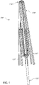
- FIG. 1 shows an assembly 100 of an umbrella.
- the assembly includes an umbrella pole 104 and canopy frame that includes an upper hub 116 and a lower hub 120.
- the lower hub 120 is moveable along the umbrella pole 104 between a lowered position (as shown in FIG. 1 ) and a raised position (not shown but between the lowered position and the position of the upper hub 116).
- the upper hub 116 and the lower hub 120 are connected to each other by a framework of rib members, including upper ribs 108 and lower ribs 112.
- the upper ribs 108 are secured at a first end to the upper hub 116 and at an end opposite the first end to a canopy member, e.g., fabric (not shown).
- the lower ribs 112 are connected to the lower hub 120 at a first end and to a point along the length of the upper ribs 108 at a second end opposite the first end.
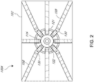
- FIG. 2 shows a modified embodiment of an umbrella 100A, which includes a frame structure to be mounted to a pole, similar to that shown in FIG. 1 .
- the umbrella 100A includes a canopy fabric 102.
- the umbrella 100A differs in providing an asymmetric shape, in this illustrated embodiment a rectangular shape.
- the umbrella 100A includes the upper hub 116 and a plurality of upper ribs 108 that extend from the upper hub 116 to a periphery of the canopy fabric 102.
- FIG. 2 shows that the umbrella 100A has a connector 130 that is configured to bend along the length thereof at a point between the end of a tubular member of the upper ribs 108 and the radially inner end of the connector 130. The bending of the connector 130 enables the longitudinal axis of the tubular member to be angled relative to a radial direction of the upper hub 116.
- FIG. 3 shows the angulation in more detail.
- the upper hub 116 can have a hub periphery 121 and a central aperture 123 disposed at a center of the upper hub 116.
- the hub periphery 121 and the central aperture 123 can be circular and a line extending perpendicularly between these circular structures can be along a radial direction.
- the upper ribs 108 can be coupled with the upper hub 116 in the channel 122.
- the upper ribs 108 can be secured to a pin 124 coupled with the body of the upper hub 116.
- the upper rib 108 can be disposed in the channel 122 at 3 o'clock and can extend radially away from the channel 122 and a longitudinal axis LA1.
- An angle B can be defined between the channel 122 in which the upper rib 108 at the 3 o'clock position is secured and an adjacent channel 122 located counterclockwise from the 3 o'clock position.
- the angle B can separate each channel 122 and the channel 122 located adjacent thereto.
- the connector 130 can bend to allow the upper rib 108 in the channel 122 adjacent to and counterclockwise of the 3 o'clock position to extend along a longitudinal axis LA2.
- the longitudinal axis LA2 can be disposed at an angle A from the longitudinal axis LA1.
- an angle C can be defined between the longitudinal axis LA2 and the radial direction of the channel 122 to which the upper rib 108 having the longitudinal axis LA2 is coupled.
- the connector 130 is useful but due to the bending at the narrow portion thereof, the connector 130 can be subject to fatigue failure.
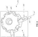
- FIG. 4 shows a hub assembly 200 that can provide advantages in eliminating bending while still providing angulation for asymmetric umbrella configurations as in FIG. 3 .
- the hub assembly 200 includes a hub 216 that has a plurality of channels 222 disposed along radial directions of the hub 216.
- the channel 222 can be provided with pin 224 to connect the upper ribs 108 thereto.
- the foregoing assumes that the hub 216 is an upper hub, but the hub 216 can be secured to the lower ribs 112 if the hub 216 is a lower hub.
- the channel 222 can be symmetrically disposed about the hub 216, e.g., extending along radial directions that are separated by equal angular distances, e.g., 45 degrees, 60 degrees, 90 degrees or other equal angular spacing.
- the channel 222 can have a common circumferential width at each position.
- the channel 222 can be configured to each receive a rib end connector 300 coupled with an elongate tubular member of a corresponding upper rib 108.
- FIG. 4 shows that the rib end connector 300 can be positioned along a longitudinal axis LA2 that is angled compared to a longitudinal axis LA1, which corresponds to a direction of a rib aligned with a radial direction of the channel 222.
- An angle D can be provided between the longitudinal axis LA1 and the longitudinal axis LA2.
- the angle D allows an upper rib 108 coupled with the channel 222 and angled as shown to reach a corner of a rectangular or other asymmetric umbrella structure, in a manner similar to that shown in FIG. 3 but without requiring bending within the rib end connector 300.
- FIG. 5 shows that the rib end connector 300 can include a rib connection portion 304 and a pin connection portion 308.
- the rib connection portion 304 can be configured to be coupled with a tubular member of the upper rib 108.
- the tubular member can be open at the first (radially inner) end.
- the rib connection portion 304 can be a reduced thickness or reduced profile projection from or compared to the pin connection portion 308 such that the rib connection portion 304 can be inserted into the tubular member.
- the tubular member wall thickness and the reduced thickness or profile portion can be sized or configured such that the tubular member of the upper rib 108 is flush with the profile of the pin connection portion 308.
- FIG. 6 shows that the rib end connector 300 can be tapered such that the end of the pin connection portion 308 opposite the rib connection portion 304 can be reduced profile compared to the location of the pin connection portion 308 adjacent to the rib connection portion 304.
- opposing side surfaces 328 can taper towards each other as they extend away from the connection portion 304 and towards a distal end of the pin connection portion.
- the pin connection portion 308 can taper to a rounded nose portion that had a profile or size less than the profile or size of the rib connection portion 304.
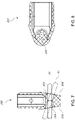
- FIGS. 7 and 8 shows that the rib end connector 300 has a varying size pin channel 320 disposed therethrough.
- the pin channel 320 can have a narrowest portion 324 disposed at a central portion of the rib end connector 300, e.g., along a longitudinal central plane of the rib end connector 300.
- the narrowest portion 324 can be sized to be slip fit over the pin 224 such that the rib end connector 300 can easily rotate about an axis that is perpendicular to the opening at the narrowest portion 324. That is the rib end connector 300 can rotate about the axis 302A (see FIG. 5 ) as the upper ribs 108 move when an umbrella with the hub assembly 200 is moved from open to closed.
- the pin channel 320 can enlarge in at least one direction away from the narrowest portion 324 (e.g., hourglass shaped).
- the pin channel 320 can enlarge in both directions away from the narrowest portion 324.
- the pin channel 320 can enlarge along a direction aligned with the rib connection portion 304 and the pin connection portion 308.
- the radially inner to radially outer dimension of the pin channel 320 can increase between the narrowest portion 324 and an opposing side surfaces 328 of the rib end connector 300. The increase in this dimension can be seen on both sides of the narrowest portion 324.
- FIG. 7 shows that the increase in this dimension can have an hourglass shape.
- the pin channel 320 can have a constant height in one embodiment.
- the height is the dimension perpendicular to the radial dimension.
- the shape of the pin channel 320 are the opposing side surfaces 328 is oval with a major axis aligned with the radial direction and a minor axis transverse to the radial direction.
- the minor axis at the opposing side surfaces 328 can be equal to the radius of the opening at the narrowest portion 324.
- the shape of the pin channel 320 allows an upper ribs 108 including the rib end connector 300 coupled to the hub 216 to be angled away from a radial direction.
- the pin channel 320 can allow a pin orientation P1 (illustrated horizontally by solid lines in FIG. 7 ) to be transverse to the opening at the narrowest portion 324 and aligned with the axis 302A.
- the pin channel 320 can allow a pin orientation P2 (illustrated angled by dashed lines in FIG. 7 ) that provides the angle D seen in FIG. 4 .
- the angle D is provided by rotating the rib end connector 300 about the axis 302B.
- the angle D can be achieved in the opposite direction by rotating the pin orientation P2 such that the right side portion thereof is above the direction P1.
- the oval shape of the pin channel 320 provides that in some embodiments an upper rib 108 with the rib end connector 300 will tilt in only one direction in addition to open-close rotation about the pin 224.
- the upper ribs 108 disposed in a central portion of the channel 222, e.g., aligned with the horizontal mid-plane of the hub 216 can tilt in the circumferential direction of the hub 216 but will not tilt about the longitudinal axis of the upper rib 108.
- This one direction tilting allows the upper rib 108 to extend along a direction that can reach a corner portion of a rectangular or other asymmetric shape while another rib can extend along the radial direction to reach another portion of a periphery of a canopy fabric 102.
- the rib end connector 300 is able to provide for angling the ribs without relying on bending of a connector.
- the pin channel 320 lacks the narrowest portion 324.
- the pin channel 320 can extend from the first opposing side surface 328 to the second opposing side surface 328 forming a slot within the rib end connector having substantially the same cross sectional shape therethrough.
- the enlarged internal shape of the pin channel 320 can also accommodate the pin orientation P2.
- the tapered first and second opposing side surfaces 328 can accommodate angling of the connection portion 304 about the axis 302B within the inner walls of the channel 222.
- the slot formed by the pin channel 320 can accommodate angling of the connection portion 304 about the axis 302B on the pin 224.
Landscapes
- Mutual Connection Of Rods And Tubes (AREA)
Abstract
Description
- This application is directed to shade structures, assemblies, and components, including umbrella assemblies and components.
- Umbrellas typically have a symmetrical configuration with an umbrella pole in the center of a canopy assembly. The canopy assembly can include upper and lower hubs with rib members that are foldable and extendable. When extended the umbrella ribs extend a shade-providing canopy over the rib members and pole. The rib members extend radially in a symmetrical manner from the hub or hubs.
- It is desired to provide shade structures and components therefor that can provide non-symmetrical shade structure and umbrella configurations. For example, a rectangular umbrella can be provided. Ribs can be supported from a central hub. The ribs can extend from the central hub to a periphery of the canopy. Some of the ribs extend radially from the hub to the periphery of the canopy. Some of the ribs extend along a direction angled from a radial direction.
- In one embodiment an umbrella rib apparatus is provided. The apparatus can be a rib end connector, a plug to receive a rib socket, or a rib to be coupled with an upper or lower hub of an umbrella or other shade structure. The apparatus includes a pin connection portion that has a first end configured to be disposed in a channel of an umbrella or other shade structure hub. The apparatus has a second portion opposite the first portion, a first side surface and a second side surface. A circumferential width of the pin connection portion is defined between the first and second lateral surfaces. A pin channel disposed between the first side surface and the second side surface. The pin channel has a narrowest portion disposed between the first side surface and the second side surface. The pin channel increases in size along at least one direction between the narrowest portion and the first side surface and/or the second side surface.
- The pin channel can increase in size in a radial direction. The pin channel can have a constant height from the first side surface to the second side surface. The pin channel can enlarge symmetrically from the narrowest portion to the first side surface and to the second side surface. The pin channel comprises an hourglass shape in longitudinal cross-section.
- At least one of the first side surface and the second side surface can be tapered toward the first end of the pin connection portion. The first side surface and the second side surface can both be tapered toward the first end.
- Features of the invention can be better understood from the following detailed description when read in conjunction with the accompanying schematic drawings, which are for illustrative purposes only. The drawings include the following figures:
-
FIG. 1 is an example of a market umbrella that can include a novel rib end connector; -
FIG. 2 is bottom view of a non-symmetrical, e.g., a rectangular, umbrella canopy assembly that can include a novel rib end connector; -
FIG. 3 is a view of a rib and hub assembly showing deflection of some ribs thereof to provide different angles of ribs extending from hubs thereof; -
FIG. 4 is a top view of one embodiment of a hub assembly that can accommodate different rib orientations aligned with or diverging from radial directions of a hub thereof; -
FIG. 5 is a perspective view of the rib end connector shown inFIG. 4 ; -
FIG. 6 is a free end view of the rib end connector shown inFIG. 4 ; -
FIG. 7 is a cross-sectional view of the rib end connector shown inFIG. 6 taken at section plane 7-7 inFIG. 6 ; -
FIG. 8 is a cross-sectional view of the rib end connector shown inFIG. 6 taken at section plane 8-8. - This application discloses an inventive umbrella and other shade structures and components for the same.
FIG. 1 shows anassembly 100 of an umbrella. The assembly includes anumbrella pole 104 and canopy frame that includes anupper hub 116 and alower hub 120. In thisumbrella assembly 100 thelower hub 120 is moveable along theumbrella pole 104 between a lowered position (as shown inFIG. 1 ) and a raised position (not shown but between the lowered position and the position of the upper hub 116). Theupper hub 116 and thelower hub 120 are connected to each other by a framework of rib members, includingupper ribs 108 andlower ribs 112. Theupper ribs 108 are secured at a first end to theupper hub 116 and at an end opposite the first end to a canopy member, e.g., fabric (not shown). Thelower ribs 112 are connected to thelower hub 120 at a first end and to a point along the length of theupper ribs 108 at a second end opposite the first end. - The
umbrella assembly 100 is often used for a shade structure that is symmetrical about theumbrella pole 104, e.g., a circular, square, hexagon, or similar shape.FIG. 2 shows a modified embodiment of anumbrella 100A, which includes a frame structure to be mounted to a pole, similar to that shown inFIG. 1 . Theumbrella 100A includes acanopy fabric 102. Theumbrella 100A differs in providing an asymmetric shape, in this illustrated embodiment a rectangular shape. Theumbrella 100A includes theupper hub 116 and a plurality ofupper ribs 108 that extend from theupper hub 116 to a periphery of thecanopy fabric 102. As can be seen some of theupper ribs 108 extend along a radius of theupper hub 116, e.g., radially relative to theupper hub 116. These hubs are seen at 3, 6, 9, and 12 o'clock inFIG. 2 . Four of theupper ribs 108 extend at a different orientation to theupper hub 116.FIG. 2 shows that theumbrella 100A has aconnector 130 that is configured to bend along the length thereof at a point between the end of a tubular member of theupper ribs 108 and the radially inner end of theconnector 130. The bending of theconnector 130 enables the longitudinal axis of the tubular member to be angled relative to a radial direction of theupper hub 116. -
FIG. 3 shows the angulation in more detail. Theupper hub 116 can have ahub periphery 121 and a central aperture 123 disposed at a center of theupper hub 116. Thehub periphery 121 and the central aperture 123 can be circular and a line extending perpendicularly between these circular structures can be along a radial direction. Theupper ribs 108 can be coupled with theupper hub 116 in thechannel 122. Theupper ribs 108 can be secured to apin 124 coupled with the body of theupper hub 116. With reference to theupper ribs 108 disposed at the 3 o'clock position, theupper rib 108 can be disposed in thechannel 122 at 3 o'clock and can extend radially away from thechannel 122 and a longitudinal axis LA1. An angle B can be defined between thechannel 122 in which theupper rib 108 at the 3 o'clock position is secured and anadjacent channel 122 located counterclockwise from the 3 o'clock position. The angle B can separate eachchannel 122 and thechannel 122 located adjacent thereto. Theconnector 130 can bend to allow theupper rib 108 in thechannel 122 adjacent to and counterclockwise of the 3 o'clock position to extend along a longitudinal axis LA2. The longitudinal axis LA2 can be disposed at an angle A from the longitudinal axis LA1. As a result, an angle C can be defined between the longitudinal axis LA2 and the radial direction of thechannel 122 to which theupper rib 108 having the longitudinal axis LA2 is coupled. Theconnector 130 is useful but due to the bending at the narrow portion thereof, theconnector 130 can be subject to fatigue failure. -
FIG. 4 shows ahub assembly 200 that can provide advantages in eliminating bending while still providing angulation for asymmetric umbrella configurations as inFIG. 3 . Thehub assembly 200 includes ahub 216 that has a plurality ofchannels 222 disposed along radial directions of thehub 216. Thechannel 222 can be provided withpin 224 to connect theupper ribs 108 thereto. The foregoing assumes that thehub 216 is an upper hub, but thehub 216 can be secured to thelower ribs 112 if thehub 216 is a lower hub. Thechannel 222 can be symmetrically disposed about thehub 216, e.g., extending along radial directions that are separated by equal angular distances, e.g., 45 degrees, 60 degrees, 90 degrees or other equal angular spacing. Thechannel 222 can have a common circumferential width at each position. Thechannel 222 can be configured to each receive arib end connector 300 coupled with an elongate tubular member of a correspondingupper rib 108.FIG. 4 shows that therib end connector 300 can be positioned along a longitudinal axis LA2 that is angled compared to a longitudinal axis LA1, which corresponds to a direction of a rib aligned with a radial direction of thechannel 222. An angle D can be provided between the longitudinal axis LA1 and the longitudinal axis LA2. The angle D allows anupper rib 108 coupled with thechannel 222 and angled as shown to reach a corner of a rectangular or other asymmetric umbrella structure, in a manner similar to that shown inFIG. 3 but without requiring bending within therib end connector 300. -
FIG. 5 shows that therib end connector 300 can include arib connection portion 304 and apin connection portion 308. Therib connection portion 304 can be configured to be coupled with a tubular member of theupper rib 108. For example, the tubular member can be open at the first (radially inner) end. Therib connection portion 304 can be a reduced thickness or reduced profile projection from or compared to thepin connection portion 308 such that therib connection portion 304 can be inserted into the tubular member. The tubular member wall thickness and the reduced thickness or profile portion can be sized or configured such that the tubular member of theupper rib 108 is flush with the profile of thepin connection portion 308. -
FIG. 6 shows that therib end connector 300 can be tapered such that the end of thepin connection portion 308 opposite therib connection portion 304 can be reduced profile compared to the location of thepin connection portion 308 adjacent to therib connection portion 304. Specifically, opposing side surfaces 328 can taper towards each other as they extend away from theconnection portion 304 and towards a distal end of the pin connection portion. Thepin connection portion 308 can taper to a rounded nose portion that had a profile or size less than the profile or size of therib connection portion 304. -
FIGS. 7 and 8 shows that therib end connector 300 has a varyingsize pin channel 320 disposed therethrough. Thepin channel 320 can have anarrowest portion 324 disposed at a central portion of therib end connector 300, e.g., along a longitudinal central plane of therib end connector 300. Thenarrowest portion 324 can be sized to be slip fit over thepin 224 such that therib end connector 300 can easily rotate about an axis that is perpendicular to the opening at thenarrowest portion 324. That is therib end connector 300 can rotate about theaxis 302A (seeFIG. 5 ) as theupper ribs 108 move when an umbrella with thehub assembly 200 is moved from open to closed. Thepin channel 320 can enlarge in at least one direction away from the narrowest portion 324 (e.g., hourglass shaped). Thepin channel 320 can enlarge in both directions away from thenarrowest portion 324. Thepin channel 320 can enlarge along a direction aligned with therib connection portion 304 and thepin connection portion 308. The radially inner to radially outer dimension of thepin channel 320 can increase between thenarrowest portion 324 and an opposing side surfaces 328 of therib end connector 300. The increase in this dimension can be seen on both sides of thenarrowest portion 324.FIG. 7 shows that the increase in this dimension can have an hourglass shape. - The
pin channel 320 can have a constant height in one embodiment. In this context, the height is the dimension perpendicular to the radial dimension. The shape of thepin channel 320 are the opposing side surfaces 328 is oval with a major axis aligned with the radial direction and a minor axis transverse to the radial direction. The minor axis at the opposing side surfaces 328 can be equal to the radius of the opening at thenarrowest portion 324. - In use, the shape of the
pin channel 320 allows anupper ribs 108 including therib end connector 300 coupled to thehub 216 to be angled away from a radial direction. Thepin channel 320 can allow a pin orientation P1 (illustrated horizontally by solid lines inFIG. 7 ) to be transverse to the opening at thenarrowest portion 324 and aligned with theaxis 302A. Thepin channel 320 can allow a pin orientation P2 (illustrated angled by dashed lines inFIG. 7 ) that provides the angle D seen inFIG. 4 . The angle D is provided by rotating therib end connector 300 about the axis 302B. The angle D can be achieved in the opposite direction by rotating the pin orientation P2 such that the right side portion thereof is above the direction P1. - The oval shape of the
pin channel 320 provides that in some embodiments anupper rib 108 with therib end connector 300 will tilt in only one direction in addition to open-close rotation about thepin 224. For example theupper ribs 108 disposed in a central portion of thechannel 222, e.g., aligned with the horizontal mid-plane of thehub 216 can tilt in the circumferential direction of thehub 216 but will not tilt about the longitudinal axis of theupper rib 108. This one direction tilting allows theupper rib 108 to extend along a direction that can reach a corner portion of a rectangular or other asymmetric shape while another rib can extend along the radial direction to reach another portion of a periphery of acanopy fabric 102. By providing such tilting therib end connector 300 is able to provide for angling the ribs without relying on bending of a connector. - In an alternative embodiment, the
pin channel 320 lacks thenarrowest portion 324. Thepin channel 320 can extend from the first opposingside surface 328 to the second opposingside surface 328 forming a slot within the rib end connector having substantially the same cross sectional shape therethrough. The enlarged internal shape of thepin channel 320 can also accommodate the pin orientation P2. The tapered first and second opposing side surfaces 328 can accommodate angling of theconnection portion 304 about the axis 302B within the inner walls of thechannel 222. The slot formed by thepin channel 320 can accommodate angling of theconnection portion 304 about the axis 302B on thepin 224.
Claims (17)
- A shade-structure rib apparatus, comprising:- a pin connection portion (308) comprising a first end configured to be disposed in a channel (222) of a shade structure hub (216), a second portion (304) opposite the first portion, a first side surface and a second side surface (328), a circumferential width of the pin connection portion (308) being defined between the first and second side surfaces (328),- a pin channel (320) disposed between the first side surface and the second side surface (328), the pin channel (320) having a narrowest portion (324) disposed between the first side surface and the second side surface (328), the pin channel (320) increasing in size along at least one direction between the narrowest portion (324) and the first side surface and/or the second side surface (328).
- The rib apparatus of Claim 1, wherein the pin channel (320) increases in size in a radial direction.
- The rib apparatus of Claim 2, wherein the pin channel (320) has a constant height from the first side surface to the second side surface (328).
- The rib apparatus of Claim 1, wherein the pin channel (320) enlarges symmetrically from the narrowest portion (324) to the first side surface and to the second side surface (328).
- The rib apparatus of Claim 1, wherein the pin channel (320) comprises an hourglass shape in longitudinal cross-section.
- The rib apparatus of Claim 1, wherein at least one of the first side surface and the second side surface (328) is tapered toward the first end.
- The rib apparatus of Claim 1, wherein the first side surface and the second side surface (328) are both tapered toward the first end.
- The rib apparatus of Claim 1, wherein the second portion (304) is configured to be secured to a tubular member of an umbrella rib (108) to provide a rib assembly.
- The rib apparatus of Claim 1, further comprising an elongate tubular member having an open end portion having the second portion dispose therein, the elongate tubular member having a free end configured to be coupled with a periphery of an umbrella canopy.
- The rib apparatus of Claim 1, further comprising an elongate tubular member extending away from the second portion to a free end, the free end configured to be coupled with a periphery of an umbrella canopy.
- A rib apparatus, comprising:- a pin connection portion (308) comprising a first end configured to be disposed in a channel (222) of a shade structure hub and a second portion (304) opposite the first portion configured to be disposed within a shade-structure rib, the first end including a first side surface and a second side surface (328) that taper together from the second portion towards a distal end of the first portion;- a pin slot (320) disposed between the first side surface and the second side surface (328), the pin slot (320) configured to allow angling of a pin (224) received therein.
- The rib apparatus of Claim 11, wherein the pin slot (320) increases in size from a narrowest portion (324) towards the first side surface and the second side surface (328).
- The rib apparatus of Claim 11, wherein the pin slot (320) has a constant height from the first side surface to the second side surface (328).
- The rib apparatus of Claim 11, wherein the pin slot (320) has a constant width from the first side surface to the second side surface (328).
- The rib apparatus of Claim 11, wherein the pin slot (320) comprises an hourglass shape in longitudinal cross-section.
- The rib apparatus of Claim 11, wherein the second portion is configured to be secured to a tubular umbrella rib (108) to provide a rib assembly.
- The rib apparatus of Claim 11, further comprising an the umbrella rib (108) having an open end portion with the second portion dispose therein.
Applications Claiming Priority (1)
| Application Number | Priority Date | Filing Date | Title |
|---|---|---|---|
| US17/213,967 US11684129B2 (en) | 2020-03-27 | 2021-03-26 | Shade structure assemblies and components |
Publications (1)
| Publication Number | Publication Date |
|---|---|
| EP4062791A1 true EP4062791A1 (en) | 2022-09-28 |
Family
ID=76159231
Family Applications (1)
| Application Number | Title | Priority Date | Filing Date |
|---|---|---|---|
| EP21020280.0A Pending EP4062791A1 (en) | 2021-03-26 | 2021-05-27 | Shade structure assemblies and components |
Country Status (1)
| Country | Link |
|---|---|
| EP (1) | EP4062791A1 (en) |
Citations (4)
| Publication number | Priority date | Publication date | Assignee | Title |
|---|---|---|---|---|
| US3431925A (en) * | 1966-08-05 | 1969-03-11 | Paul Kraft | Umbrellas |
| US5715853A (en) * | 1997-01-06 | 1998-02-10 | Asia Umbrella Industries Co., Ltd. | Structure for combining frames of an umbrella |
| CN201061309Y (en) * | 2007-01-30 | 2008-05-21 | 金祚献 | Joint of umbrella stick |
| EP2460432A2 (en) * | 2010-12-02 | 2012-06-06 | John David Di Cesare | Rib structure of umbrellas |
-
2021
- 2021-05-27 EP EP21020280.0A patent/EP4062791A1/en active Pending
Patent Citations (4)
| Publication number | Priority date | Publication date | Assignee | Title |
|---|---|---|---|---|
| US3431925A (en) * | 1966-08-05 | 1969-03-11 | Paul Kraft | Umbrellas |
| US5715853A (en) * | 1997-01-06 | 1998-02-10 | Asia Umbrella Industries Co., Ltd. | Structure for combining frames of an umbrella |
| CN201061309Y (en) * | 2007-01-30 | 2008-05-21 | 金祚献 | Joint of umbrella stick |
| EP2460432A2 (en) * | 2010-12-02 | 2012-06-06 | John David Di Cesare | Rib structure of umbrellas |
Similar Documents
| Publication | Publication Date | Title |
|---|---|---|
| US8061375B2 (en) | Adjustable rib connectors | |
| KR102792133B1 (en) | Grommet removal assemblies and methods | |
| US11519193B2 (en) | Rotation base for umbrella | |
| US11684129B2 (en) | Shade structure assemblies and components | |
| US20200315306A1 (en) | Quick assembly methods and components for shade structures | |
| US11066870B1 (en) | Barrier having upside down joint | |
| US20090076550A1 (en) | Spinal fixation system connectors | |
| US20200216037A1 (en) | Windshield wiper connector | |
| US11611310B2 (en) | Hinged solar mount | |
| US8166986B2 (en) | Quick connector hub for shade structure | |
| US20140305476A1 (en) | Umbrella rib connector | |
| JPS61286470A (en) | Center section unit consisting of hub and strut end cap for tent | |
| US20050127261A1 (en) | Pivotal shaft assembly for plane displays | |
| US10787835B2 (en) | Play structure tube connector and system | |
| CN113940609B (en) | Endoscopic snake bone and endoscope | |
| US20220010581A1 (en) | Foldable frame for a tent | |
| EP4062791A1 (en) | Shade structure assemblies and components | |
| US12188251B2 (en) | Tent couplers | |
| US5860902A (en) | Paint roller frame with an adjustable handle | |
| US20230272800A1 (en) | Down rod hanger system of ceiling fan | |
| US12317976B2 (en) | Shade structure assemblies and components | |
| JP6099939B2 (en) | Sealing handle device | |
| US20180195329A1 (en) | Hinges | |
| CN111521169A (en) | A multifunctional electric pole auxiliary measurement and positioning tool | |
| KR19990007668A (en) | Tent with pole pole connector for free angle adjustment of pole pole |
Legal Events
| Date | Code | Title | Description |
|---|---|---|---|
| PUAI | Public reference made under article 153(3) epc to a published international application that has entered the european phase |
Free format text: ORIGINAL CODE: 0009012 |
|
| STAA | Information on the status of an ep patent application or granted ep patent |
Free format text: STATUS: THE APPLICATION HAS BEEN PUBLISHED |
|
| AK | Designated contracting states |
Kind code of ref document: A1 Designated state(s): AL AT BE BG CH CY CZ DE DK EE ES FI FR GB GR HR HU IE IS IT LI LT LU LV MC MK MT NL NO PL PT RO RS SE SI SK SM TR |
|
| STAA | Information on the status of an ep patent application or granted ep patent |
Free format text: STATUS: REQUEST FOR EXAMINATION WAS MADE |
|
| 17P | Request for examination filed |
Effective date: 20230622 |
|
| RBV | Designated contracting states (corrected) |
Designated state(s): AL AT BE BG CH CY CZ DE DK EE ES FI FR GB GR HR HU IE IS IT LI LT LU LV MC MK MT NL NO PL PT RO RS SE SI SK SM TR |
|
| STAA | Information on the status of an ep patent application or granted ep patent |
Free format text: STATUS: EXAMINATION IS IN PROGRESS |
|
| 17Q | First examination report despatched |
Effective date: 20240711 |