EP4062739A1 - System and method for controlling an agricultural header - Google Patents
System and method for controlling an agricultural header Download PDFInfo
- Publication number
- EP4062739A1 EP4062739A1 EP22164526.0A EP22164526A EP4062739A1 EP 4062739 A1 EP4062739 A1 EP 4062739A1 EP 22164526 A EP22164526 A EP 22164526A EP 4062739 A1 EP4062739 A1 EP 4062739A1
- Authority
- EP
- European Patent Office
- Prior art keywords
- header
- distance
- sensor
- agricultural
- controller
- Prior art date
- Legal status (The legal status is an assumption and is not a legal conclusion. Google has not performed a legal analysis and makes no representation as to the accuracy of the status listed.)
- Pending
Links
- 238000000034 method Methods 0.000 title claims description 28
- 239000002689 soil Substances 0.000 claims description 29
- 230000004044 response Effects 0.000 description 10
- 230000008569 process Effects 0.000 description 9
- 239000000463 material Substances 0.000 description 7
- 238000003306 harvesting Methods 0.000 description 6
- 239000010908 plant waste Substances 0.000 description 6
- 241000251169 Alopias vulpinus Species 0.000 description 4
- 241000196324 Embryophyta Species 0.000 description 4
- 238000010586 diagram Methods 0.000 description 4
- 238000003860 storage Methods 0.000 description 4
- 230000032258 transport Effects 0.000 description 4
- 240000008042 Zea mays Species 0.000 description 2
- 235000005824 Zea mays ssp. parviglumis Nutrition 0.000 description 2
- 235000002017 Zea mays subsp mays Nutrition 0.000 description 2
- 238000004140 cleaning Methods 0.000 description 2
- 235000005822 corn Nutrition 0.000 description 2
- 238000001514 detection method Methods 0.000 description 2
- 235000007319 Avena orientalis Nutrition 0.000 description 1
- 244000075850 Avena orientalis Species 0.000 description 1
- 235000016068 Berberis vulgaris Nutrition 0.000 description 1
- 241000335053 Beta vulgaris Species 0.000 description 1
- 229920000742 Cotton Polymers 0.000 description 1
- 244000000626 Daucus carota Species 0.000 description 1
- 235000002767 Daucus carota Nutrition 0.000 description 1
- 244000068988 Glycine max Species 0.000 description 1
- 235000010469 Glycine max Nutrition 0.000 description 1
- 241000219146 Gossypium Species 0.000 description 1
- 240000005979 Hordeum vulgare Species 0.000 description 1
- 235000007340 Hordeum vulgare Nutrition 0.000 description 1
- 235000004431 Linum usitatissimum Nutrition 0.000 description 1
- 240000006240 Linum usitatissimum Species 0.000 description 1
- 244000046052 Phaseolus vulgaris Species 0.000 description 1
- 235000010627 Phaseolus vulgaris Nutrition 0.000 description 1
- 241000209056 Secale Species 0.000 description 1
- 235000007238 Secale cereale Nutrition 0.000 description 1
- 244000061456 Solanum tuberosum Species 0.000 description 1
- 235000002595 Solanum tuberosum Nutrition 0.000 description 1
- 235000021307 Triticum Nutrition 0.000 description 1
- 244000098338 Triticum aestivum Species 0.000 description 1
- 235000013339 cereals Nutrition 0.000 description 1
- 230000007613 environmental effect Effects 0.000 description 1
- 238000009313 farming Methods 0.000 description 1
- 230000005484 gravity Effects 0.000 description 1
- 239000010903 husk Substances 0.000 description 1
- 230000007246 mechanism Effects 0.000 description 1
- 230000000149 penetrating effect Effects 0.000 description 1
- 235000012015 potatoes Nutrition 0.000 description 1
- 239000007787 solid Substances 0.000 description 1
- 230000007480 spreading Effects 0.000 description 1
Images


Classifications
-
- A—HUMAN NECESSITIES
- A01—AGRICULTURE; FORESTRY; ANIMAL HUSBANDRY; HUNTING; TRAPPING; FISHING
- A01D—HARVESTING; MOWING
- A01D41/00—Combines, i.e. harvesters or mowers combined with threshing devices
- A01D41/12—Details of combines
- A01D41/14—Mowing tables
- A01D41/141—Automatic header control
-
- A—HUMAN NECESSITIES
- A01—AGRICULTURE; FORESTRY; ANIMAL HUSBANDRY; HUNTING; TRAPPING; FISHING
- A01D—HARVESTING; MOWING
- A01D41/00—Combines, i.e. harvesters or mowers combined with threshing devices
- A01D41/06—Combines with headers
-
- A—HUMAN NECESSITIES
- A01—AGRICULTURE; FORESTRY; ANIMAL HUSBANDRY; HUNTING; TRAPPING; FISHING
- A01D—HARVESTING; MOWING
- A01D41/00—Combines, i.e. harvesters or mowers combined with threshing devices
- A01D41/12—Details of combines
- A01D41/127—Control or measuring arrangements specially adapted for combines
- A01D41/1278—Control or measuring arrangements specially adapted for combines for automatic steering
Definitions
- the present disclosure generally relates to systems and method for controlling an agricultural header.
- a harvester may be used to harvest crops, such as barley, beans, beets, carrots, corn, cotton, flax, oats, potatoes, rye, soybeans, wheat, or other plant crops.
- crops such as barley, beans, beets, carrots, corn, cotton, flax, oats, potatoes, rye, soybeans, wheat, or other plant crops.
- the course of the harvester may be adjusted to position a header along certain rows of crops.
- the height and angle of the header may also be adjusted to properly harvest the crops.
- the header may have a set of sensor(s) for sensing row alignment, sensing the height of the header off the ground, sensing the height of a crop canopy, or the like.
- the sensors may be attached to the harvester, the header, one or more structures attached thereto, or a combination thereof.
- an agricultural system includes a controller comprising a memory and a processor, wherein the controller is configured to receive data from a first and second sensor, each of which are mounted on an agricultural header and configured to output data indicative of one-dimensional (ID) distances.
- the controller is configured to determine a first horizontal distance from the first sensor to a first plant stalk and a second horizontal distance from the second sensor to a second plant stalk based on the 1D distance data.
- the controller is also configured to control a steering system of the agricultural system to adjust a position of the agricultural header relative to the first and second plant stalks based on a difference between the first horizontal distance and the second horizontal distance.
- the process of farming typically begins with planting seeds within a field. Over time, the seeds grow and eventually become harvestable crops. Typically, only a portion of each crop is commercially valuable, so each crop is harvested to separate the usable material from the remainder of the crop.
- a harvester may cut crops within a field via a header.
- the harvester may be at least partially automated so as to harvest crops at least partially independent of human control. During automated harvesting, the harvester may encounter curved crop rows, inclined soil surfaces, as well as crops of varying canopy height. Accordingly, the harvester may be outfitted with a variety of sensors.
- the harvester may utilize data gathered from the sensors to adjust row alignment, header height, and header angle in response to the environment.
- the harvester and header may be outfitted with sensors for sensing row alignment, canopy height, header height above the ground, soil surface incline, and the like. Each piece of data in the above list may be sensed by one or more distinct sensors.
- a harvester guidance system utilizing a single sensor type may simplify automated harvester guidance systems and decrease cost of the harvester.
- the present disclosure is directed to a control system including a pair of multi-purpose sensors that may be utilized to automate row alignment, header height, header angle, and the like.
- a pair of one-dimensional (ID) sensors may face in a perpendicular direction to the motion of the harvester.
- the sensors may also point partially toward the ground and partially toward the horizon, so as to detect the vertical distance from the header to the ground and the horizontal distance from a part of the header to the nearest crop stalk.
- a control system may use the data collected from the sensors to control the row alignment, header height, and header angle.
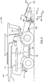
- FIG. 1 is a side view of an embodiment of an agricultural system 100, which may be a harvester.
- the agricultural system 100 includes a chassis 102 configured to support a header 200 and an agricultural crop processing system 104.
- the header 200 is configured to cut crops and to transport the cut crops toward an inlet 106 of the agricultural crop processing system 104 for further processing of the cut crops.
- the agricultural crop processing system 104 receives the cut crops from the header 200 and separates desired crop material from crop residue.
- the agricultural crop processing system 104 may include a thresher 108 having a cylindrical threshing rotor that transports the crops in a helical flow path through the agricultural system 100.
- the thresher 108 may separate certain desired crop material (e.g., grain) from the crop residue, such as husks and pods, and may enable the desired crop material to flow into a cleaning system 114 (such as sieves) located beneath the thresher 108.
- the cleaning system 114 may remove debris from the desired crop material and transport the desired crop material to a storage tank 116 within the agricultural system 100.
- a tractor with a trailer may pull alongside the agricultural system 100.
- the desired crop material collected in the storage tank 116 may be carried up by an elevator and dumped out of an unloader 118 into the trailer.
- the crop residue may be transported from the thresher 108 to a crop residue handling system 110, which may process (e.g., chop/shred) and remove the crop residue from the agricultural system 100 via a crop residue spreading system 112 positioned at an aft end of the agricultural system 100.
- a crop residue handling system 110 may process (e.g., chop/shred) and remove the crop residue from the agricultural system 100 via a crop residue spreading system 112 positioned at an aft end of the agricultural system 100.
- the agricultural system 100 and/or its components may be described with reference to a lateral axis or direction 140, a longitudinal axis or direction 142, and a vertical axis or direction 144. Each axis is fixed and independent of the orientation of the header 200.
- the agricultural system 100 and/or its components may also be described with reference to a direction of travel 146.
- the agricultural system 100 may include one or more actuators configured to manipulate the spatial orientation and/or position of the header with respect to the agricultural system chassis, and/or the spatial orientation of the header with respect to the crop rows, or ground/soil.
- a header height actuator 226 may drive the header 200 to move along the direction 144 relative to the ground.
- the header 200 may be attached to the chassis via a four bar linkage. The position of the four bar linkage may be manipulated by the header height actuator 226 to adjust the height of the header.
- the agricultural system 100 may also include a header orientation actuator 228.
- the header orientation actuator 228 may be configured to rotate the angular orientation of the header 200 relative to the ground.
- the agricultural system 100 may also include a steering system 230.
- the steering system 230 may be configured to control the trajectory of the agricultural system 100 and the header 200 along a path.
- the steering system may include one or more mechanical and electronic components configured to manipulate the steering components of the agricultural system, such as a set of wheels.
- the actuators and steering system may be manipulated in response to one or more stimuli to adjust the agricultural system 100 to one or more environmental variables (e.g., soil condition, terrain, crop damage, etc.).
- FIG. 2 is a perspective view of an embodiment of the header 200 that may be employed within the agricultural system 100 of FIG. 1 .
- the header 200 includes multiple separators 202 configured to separate rows of a crop (e.g., corn).
- the separators 202 may be evenly spaced along the header horizontally.
- the separators 202 may direct crops from each row to one or more row units 204.
- the row units 204 are configured to cut a portion of each crop (e.g., a stalk), thereby separating the crop from the soil.
- the cut crop may be directed to one of a pair of augers 206 configured to convey the cut crop laterally inward to a crop conveyor 208 at the center of the header.
- the augers 206 extend along a substantial portion of the width of the header 200 (e.g., along the lateral axis 140).
- the augers 206 may be driven by a driving mechanism located (e.g., electric motor, hydraulic motor, etc.).
- a driving mechanism located (e.g., electric motor, hydraulic motor, etc.).
- the separators 202 direct the rows of crops into the row units 204.
- the row units engage and cut the crops within the field, and the augers 206 transport the cut crop to the crop conveyor 208, which directs the crops to toward the inlet of the agricultural crop processing system.
- the header 200 includes one or more sensor mounts 224.
- Each sensor mount may include a structure (e.g., truss, tube, solid member, etc.) that holds one or more sensors in desired location(s) (e.g., relative to the frame 201).
- the sensor mounts may attach to any portion of the header 200, and may have a geometry that orients the attached sensors in a target direction.
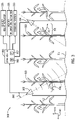
- FIG. 3 is a schematic diagram of an embodiment of a control system 300 that may be employed within the agricultural system of FIG. 1 .
- the control system 300 includes a left sensor 302 and a right sensor 304.
- the left sensor 302 and the right sensor 304 may include any suitable type(s) of sensor(s) (e.g., light detection and ranging (LIDAR) sensor(s), radio detection and ranging (radar) sensor(s), etc.) configured to output one-dimensional (ID) distance data.
- the sensors may be configured to output two-dimensional (2D) distance data.
- Each sensor may be positioned ahead of the header along the direction of travel (e.g., mounted on a respective sensor mount disclosed above with reference to FIG.
- each sensor may be angled partially downward and partially horizontally toward the centerline of the header.
- the right sensor 304 may be mounted near the right edge of the header 200 and angled 45 degrees below the lateral axis or direction 140 within the plane created by the lateral axis or direction 140 and the vertical axis or direction 144.
- the left sensor 302 may be mounted near the left edge of the header 200 and angled 45 degrees below the lateral axis or direction 140 within the plane created by the lateral axis or direction 140 and the vertical axis or direction 144.
- each sensor may be angled outward, toward the edges of the header.
- the left sensor 302 and right sensor 304 may each output data indicative of the distance from the sensor to a target object (e.g., the crops being harvested, the ground/soil surface, etc.).
- the sensors are configured to output the data to a controller.
- the sensors may be mounted anywhere in between the centerline of the header and the edges of the header.
- the control system 300 includes a controller 305 configured to receive data from the sensors and to control operation of at least a portion of the agricultural system, such as the alignment of the header with the crop row, and the height and angle of the header.
- the controller 305 includes a memory 306 and a processor 307 (e.g., a microprocessor).
- the controller 305 may also include one or more storage devices and/or other suitable components.
- the processor 307 may be used to execute software, such as software for controlling the agricultural system and/or the header.
- the processor 307 may include multiple microprocessors, one or more "general-purpose" microprocessors, one or more special-purpose microprocessors, and/or one or more application specific integrated circuits (ASICS), or some combination thereof.
- ASICS application specific integrated circuits
- the processor 307 may include one or more reduced instruction set (RISC) or complex instruction set (CISC) processors.
- the memory 306 may include a volatile memory, such as random access memory (RAM), and/or a nonvolatile memory, such as read-only memory (ROM).
- RAM random access memory
- ROM read-only memory
- the memory 306 may store a variety of information and may be used for various purposes.
- the memory 306 may store processor-executable instructions (e.g., firmware or software) for the processor 307 to execute, such as instructions for controlling the agricultural system and/or the header.
- the memory 306 and/or the processor 307, or an additional memory and/or processor may be located in any suitable portion of the agricultural system.
- the controller 305 may be located in a cab of the agricultural system and/or on the header.
- the controller 305 is communicatively coupled to the sensors 302, 304 and configured to receive data from the sensors.
- the left sensor 302 and the right sensor 304 may each output 1D distance data to the controller 305, and the controller 305 may control the agricultural system (e.g., header row alignment, header height, header angle, or a combination thereof) based on the 1D distance data from the sensors.
- the left sensor 302 and/or the right sensor 304 may output one-dimensional distance data in real time or near real time.
- the controller 305 may use the 1D distance data from the left sensor 302, along with a left angle 308, to determine a left horizontal distance 309 from the left sensor 302 to the left stalk 310.
- the left angle 308 may be an angle between the vertical axis 144 and a 1D line sensed by left sensor 302.
- the controller 305 may determine a left vertical distance 312 from the left sensor 302 to the soil surface 314 based on the 1D distance data from the left sensor 302 and a right angle 311.
- the right angle 311 may be an angle between the vertical axis 144 and a 1D line sensed by right sensor 304.
- the controller 305 may also determine a right horizontal distance 316 and a right vertical distance 318 based on the 1D distance data from the right sensor 304.
- the controller 305 may use the left horizontal distance 309, the left vertical distance 312, the right horizontal distance 316, and the right vertical distance 320 to facilitate automatic control of at least a portion of the agricultural system 100.
- the controller 305 may control the one or more actuators of the agricultural system 100 to automatically adjust the row alignment of the header, the header height, the header angle, or a combination thereof.
- the controller 305 may be communicatively coupled to the header height actuator 226 and may be configured to output control signals to the actuator to adjust the height of the header relative to the agricultural system chassis.
- the controller 305 may determine that the left vertical distance 312 and right vertical distance 320 are below a certain height threshold value.
- the controller 305 may control the header height actuator 226 to raise the header so that it is in the threshold range value. In another example, the controller 305 may determine that the left vertical distance 312 and right vertical distance 320 are above the height threshold range value. In response, the controller 305 may control the header height actuator 226 to lower the header so that it is within the threshold range value.
- the controller 305 may also be communicatively coupled to the header orientation actuator 228 and may be configured to output control signals to the actuator to adjust the angular orientation of the header relative to the agricultural system chassis. For example, the controller 305 may determine that a difference between the left vertical distance 312 and the right vertical distance 320 is greater than a threshold range value.
- the controller 305 may cause the header orientation actuator 228 to rotate the header until the difference between the left vertical distance 312 and the right vertical distance 320 is less than the threshold range value.
- the controller 305 may also be configured to be communicatively coupled to the steering system 230 and may be configured to output control signals to the steering system to adjust the row alignment of the agricultural system 100 and the header 200. For example, the controller 305 may determine that the left horizontal distance 309 exceeds the right horizontal distance 316 greater than a threshold range value. In response, the controller 305 may cause the steering system 230 to turn the agricultural system 100 to the right to align with the crop rows. Alternatively, in one example the controller 305 may determine that the right horizontal distance 316 exceeds the left horizontal distance 309 greater than the threshold range value. In response, the controller 305 may cause the steering system 230 to turn the agricultural system 100 to the left to align with the crop rows. In this embodiment, as well as the embodiments disclosed above, the processor 305 may perform the method described below.
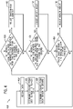
- FIG. 4 is a flowchart of an embodiment of a method 400 for adjusting header alignment, height, and angle.
- the method 400 may be performed via the controller disclosed above, or another suitable device. Further, the method 400 may be performed differently in additional or alternative embodiments. For instance, additional steps may be performed with respect to the method 400, and/or certain steps of the method 400 may be modified, removed, performed in a different order, or a combination thereof.
- the method 400 may be performed based on data received from the one-dimensional sensors of FIG. 3 , and/or based on data received from two-dimensional sensor(s) mounted above the crop rows. The method 400 may also be performed based on an embodiment of FIG. 3 including one sensor.
- the left sensor and the right sensor may output 1D distance data to the controller.
- the 1D distance data may be indicative of the linear distance between each sensor and the nearest crop stalk, as well as the linear distance between the sensor and the soil surface.
- at least one sensor may output 1D distance data indicative of distance values between the sensor and the nearest object(s) (e.g., the nearest crop stalk, the soil surface, etc.).
- at least one sensor may be capable of sending data concerning two points at once in its line of sight. The sensor may measure a distance between the sensor and a stalk, as well as the distance between the sensor and the soil surface 314 at once. The sensor may measure two points at once by penetrating through the stalk.
- the data is analyzed to determine the distance from each sensor to the nearest crop stalk.
- the horizontal component of the distance is then determined.
- the left horizontal distance may be determined based on the angle of the left sensor and the linear distance between the left sensor and the left stalk.
- the right horizontal distance may be determined based on the angle of the right sensor and the linear distance between the right sensor and the right stalk.
- the data may be 2D, and the controller may selectively utilize 1D data from a plane of the 2D data.
- the data may be analyzed from one sensor to determine one distance (e.g., from the left sensor to the left stalk).
- the data is analyzed to determine the distance from each sensor to the soil surface 314. Similar to block 406, the vertical component of the distance may be determined based on the left angle 308 and the linear distance between the left sensor 302 and the soil surface 314 to determine the left vertical distance 312. In addition, the right vertical distance 320 may be determined based on the right angle 311 of the right sensor and the linear distance between the right sensor and the soil surface 314. In other embodiments, the data may be analyzed from one sensor to determine one distance (e.g., from the left sensor to the soil surface).
- a difference in distances may be indicative of misalignment between the header and the rows of crops being harvested. For instance, if the left horizontal distance is greater than the right horizontal distance, the header may be following a course that veers left of the targeted crop rows. The misalignment may be due to a curve in the rows, soil conditions, or the like.
- a determination is made regarding whether a single distance is within a threshold range value e.g., whether the left horizontal distance is within a threshold range. If the difference between the left horizontal distance and the right horizontal distance is greater than the threshold range value, the process may continue to block 410. If not, the process may continue to block 412.
- the course of the agricultural system is adjusted.
- the course of the agricultural system may be adjusted to realign the header with the targeted crop rows.
- the direction of the agricultural system may be adjusted so that the difference between the left horizontal distance and the right horizontal distance is less than the threshold range value. For example, if the right horizontal distance is greater than the left horizontal distance, the course of the agricultural system may be adjusted to the left.
- the processor may control the steering system 230 to adjust the course.
- the controller 305 may determine whether the difference between the left vertical distance and the right vertical distance is greater than a threshold range value.
- a difference in distances may indicate that the header is not parallel to the soil surface. For instance, if the left vertical distance is greater than the right vertical distance, the header may be angled askew of the soil surface. If the difference between the left vertical distance and the right vertical distance is greater than the threshold range value, the process may continue to block 414. If not, the process may continue to block 416.
- the angle of the header relative to the soil surface may be adjusted.
- the header may be rotated based on the left vertical distance and the right vertical distance.
- the header may be rotated until the header is substantially even with the soil surface.
- the header may be substantially parallel to the soil surface once the difference between the left vertical distance and the right vertical distance is less than the threshold range value.
- the header may be rotated counterclockwise until the difference between the left vertical distance and right vertical distance is less than the threshold range value.
- the processor may control the header orientation actuator 228 to rotate the header.
- the angle of the header may be rotated based on a single distance (e.g., the left vertical distance) and data received from one or more rotation sensors installed on the header and the agricultural system and configured to send data regarding the angle of the header relative to the soil surface.
- the threshold range may be a header height range at which the harvested crop retains an undesirable length of stalk.
- the threshold range may be determined by the controller 305, or manually input by a user. If the left vertical distance 312, the right horizontal distance 320, both, an average, or any mathematical combination of the two are below the threshold range, the process may continue to block 418. If not, the process may continue to block 402 and repeat the method 400. In another embodiment, a determination is made regarding whether a single distance is greater than a threshold range value (e.g., whether the left vertical distance is greater than a threshold range value).
- the height of the header is adjusted.
- the height of the header may be raised or lowered so that the left vertical distance 312, the right horizontal distance 320, both, or an average of the two are within the threshold range. For example, if the left vertical distance and right vertical distance are equal and above the threshold range, the height of the header may be lowered to be within the threshold range.
- the header 200 may also be rotated until it is parallel with the soil surface before the height of the header is adjusted.
- the processor may control the header height actuator 226 to rotate the header.
- the process may repeat the method 400 as the agricultural system 100 harvests crops.
- FIG. 5 is a schematic diagram of an embodiment of the control system 300 of FIG. 3 .
- the agricultural system operates on an inclined surface 502.
- the crops, such as left stalk 504 and right stalk 506 may grow at an angle to the inclined surface 502.
- the header 200 may be angled substantially parallel to the inclined surface 502.
- the controller may adjust the course of the agricultural system 100 in response to downhill vehicle drift.
- the agricultural system may drift downhill under the influence of gravity. Due to this drifting, the left horizontal distance 309 may grow larger than the right horizontal distance 316.
- the controller may adjust the course of the agricultural system 100 to the right.
Landscapes
- Life Sciences & Earth Sciences (AREA)
- Environmental Sciences (AREA)
- Guiding Agricultural Machines (AREA)
Abstract
Description
- The present disclosure generally relates to systems and method for controlling an agricultural header.
- A harvester may be used to harvest crops, such as barley, beans, beets, carrots, corn, cotton, flax, oats, potatoes, rye, soybeans, wheat, or other plant crops. The course of the harvester may be adjusted to position a header along certain rows of crops. The height and angle of the header may also be adjusted to properly harvest the crops. In addition, the header may have a set of sensor(s) for sensing row alignment, sensing the height of the header off the ground, sensing the height of a crop canopy, or the like. The sensors may be attached to the harvester, the header, one or more structures attached thereto, or a combination thereof.
- Certain embodiments commensurate in scope with the originally claimed subject matter are summarized below. These embodiments are not intended to limit the scope of the claimed subject matter, but rather these embodiments are intended only to provide a brief summary of possible forms of the disclosure. Indeed, the disclosure may encompass a variety of forms that may be similar to or different from the embodiments set forth below.
- In certain embodiments, an agricultural system includes a controller comprising a memory and a processor, wherein the controller is configured to receive data from a first and second sensor, each of which are mounted on an agricultural header and configured to output data indicative of one-dimensional (ID) distances. The controller is configured to determine a first horizontal distance from the first sensor to a first plant stalk and a second horizontal distance from the second sensor to a second plant stalk based on the 1D distance data. The controller is also configured to control a steering system of the agricultural system to adjust a position of the agricultural header relative to the first and second plant stalks based on a difference between the first horizontal distance and the second horizontal distance.
- These and other features, aspects, and advantages of the present disclosure will become better understood when the following detailed description is read with reference to the accompanying drawings in which like characters represent like parts throughout the drawings, wherein:
-
FIG. 1 is a side view of an embodiment of an agricultural system, in accordance with an aspect of the present disclosure; -
FIG. 2 is a perspective view of an embodiment of a header that may be employed within the agricultural system ofFIG. 1 , in accordance with an aspect of the present disclosure; -
FIG. 3 is a schematic diagram of an embodiment of a control system that may be employed within the agricultural system ofFIG. 1 , in accordance with an aspect of the present disclosure; -
FIG. 4 is a flowchart of an embodiment of a method for adjusting header alignment, height, and angle, in accordance with an aspect of the present disclosure; and -
FIG. 5 is a schematic diagram of an embodiment of the control system ofFIG. 3 , in which the harvester operates on an inclined surface, in accordance with an aspect of the present disclosure. - The process of farming typically begins with planting seeds within a field. Over time, the seeds grow and eventually become harvestable crops. Typically, only a portion of each crop is commercially valuable, so each crop is harvested to separate the usable material from the remainder of the crop. For example, a harvester may cut crops within a field via a header. The harvester may be at least partially automated so as to harvest crops at least partially independent of human control. During automated harvesting, the harvester may encounter curved crop rows, inclined soil surfaces, as well as crops of varying canopy height. Accordingly, the harvester may be outfitted with a variety of sensors. The harvester may utilize data gathered from the sensors to adjust row alignment, header height, and header angle in response to the environment. The harvester and header may be outfitted with sensors for sensing row alignment, canopy height, header height above the ground, soil surface incline, and the like. Each piece of data in the above list may be sensed by one or more distinct sensors.
- A harvester guidance system utilizing a single sensor type may simplify automated harvester guidance systems and decrease cost of the harvester. The present disclosure is directed to a control system including a pair of multi-purpose sensors that may be utilized to automate row alignment, header height, header angle, and the like. For instance, a pair of one-dimensional (ID) sensors may face in a perpendicular direction to the motion of the harvester. The sensors may also point partially toward the ground and partially toward the horizon, so as to detect the vertical distance from the header to the ground and the horizontal distance from a part of the header to the nearest crop stalk. A control system may use the data collected from the sensors to control the row alignment, header height, and header angle.
- With the foregoing in mind,
FIG. 1 is a side view of an embodiment of anagricultural system 100, which may be a harvester. Theagricultural system 100 includes achassis 102 configured to support aheader 200 and an agriculturalcrop processing system 104. As described in greater detail below, theheader 200 is configured to cut crops and to transport the cut crops toward aninlet 106 of the agriculturalcrop processing system 104 for further processing of the cut crops. The agriculturalcrop processing system 104 receives the cut crops from theheader 200 and separates desired crop material from crop residue. For example, the agriculturalcrop processing system 104 may include athresher 108 having a cylindrical threshing rotor that transports the crops in a helical flow path through theagricultural system 100. In addition to transporting the crops, thethresher 108 may separate certain desired crop material (e.g., grain) from the crop residue, such as husks and pods, and may enable the desired crop material to flow into a cleaning system 114 (such as sieves) located beneath thethresher 108. Thecleaning system 114 may remove debris from the desired crop material and transport the desired crop material to astorage tank 116 within theagricultural system 100. When thestorage tank 116 is full, a tractor with a trailer may pull alongside theagricultural system 100. The desired crop material collected in thestorage tank 116 may be carried up by an elevator and dumped out of anunloader 118 into the trailer. The crop residue may be transported from thethresher 108 to a cropresidue handling system 110, which may process (e.g., chop/shred) and remove the crop residue from theagricultural system 100 via a cropresidue spreading system 112 positioned at an aft end of theagricultural system 100. To facilitate discussion, theagricultural system 100 and/or its components may be described with reference to a lateral axis ordirection 140, a longitudinal axis ordirection 142, and a vertical axis ordirection 144. Each axis is fixed and independent of the orientation of theheader 200. Theagricultural system 100 and/or its components may also be described with reference to a direction of travel 146. - In the illustrated embodiment, the
agricultural system 100 may include one or more actuators configured to manipulate the spatial orientation and/or position of the header with respect to the agricultural system chassis, and/or the spatial orientation of the header with respect to the crop rows, or ground/soil. Aheader height actuator 226 may drive theheader 200 to move along thedirection 144 relative to the ground. Theheader 200 may be attached to the chassis via a four bar linkage. The position of the four bar linkage may be manipulated by theheader height actuator 226 to adjust the height of the header. Theagricultural system 100 may also include aheader orientation actuator 228. Theheader orientation actuator 228 may be configured to rotate the angular orientation of theheader 200 relative to the ground. Theagricultural system 100 may also include asteering system 230. Thesteering system 230 may be configured to control the trajectory of theagricultural system 100 and theheader 200 along a path. The steering system may include one or more mechanical and electronic components configured to manipulate the steering components of the agricultural system, such as a set of wheels. The actuators and steering system may be manipulated in response to one or more stimuli to adjust theagricultural system 100 to one or more environmental variables (e.g., soil condition, terrain, crop damage, etc.). -
FIG. 2 is a perspective view of an embodiment of theheader 200 that may be employed within theagricultural system 100 ofFIG. 1 . In the illustrated embodiment, theheader 200 includesmultiple separators 202 configured to separate rows of a crop (e.g., corn). Theseparators 202 may be evenly spaced along the header horizontally. As the header moves along the path, theseparators 202 may direct crops from each row to one ormore row units 204. Therow units 204 are configured to cut a portion of each crop (e.g., a stalk), thereby separating the crop from the soil. The cut crop may be directed to one of a pair ofaugers 206 configured to convey the cut crop laterally inward to acrop conveyor 208 at the center of the header. As illustrated, theaugers 206 extend along a substantial portion of the width of the header 200 (e.g., along the lateral axis 140). Theaugers 206 may be driven by a driving mechanism located (e.g., electric motor, hydraulic motor, etc.). As theagricultural system 100 is driven through the field, theseparators 202 direct the rows of crops into therow units 204. The row units engage and cut the crops within the field, and theaugers 206 transport the cut crop to thecrop conveyor 208, which directs the crops to toward the inlet of the agricultural crop processing system. - In the illustrated embodiment, the
header 200 includes one or more sensor mounts 224. Each sensor mount may include a structure (e.g., truss, tube, solid member, etc.) that holds one or more sensors in desired location(s) (e.g., relative to the frame 201). The sensor mounts may attach to any portion of theheader 200, and may have a geometry that orients the attached sensors in a target direction. - With this in mind,
FIG. 3 is a schematic diagram of an embodiment of acontrol system 300 that may be employed within the agricultural system ofFIG. 1 . In the illustrated embodiment, thecontrol system 300 includes aleft sensor 302 and aright sensor 304. Theleft sensor 302 and theright sensor 304 may include any suitable type(s) of sensor(s) (e.g., light detection and ranging (LIDAR) sensor(s), radio detection and ranging (radar) sensor(s), etc.) configured to output one-dimensional (ID) distance data. In another embodiment, the sensors may be configured to output two-dimensional (2D) distance data. Each sensor may be positioned ahead of the header along the direction of travel (e.g., mounted on a respective sensor mount disclosed above with reference toFIG. 2 ) and oriented to point generally perpendicularly to the direction of travel (e.g., substantially perpendicularly, or approximately 90 degrees with respect to the axis). Additionally, each sensor may be angled partially downward and partially horizontally toward the centerline of the header. For example, theright sensor 304 may be mounted near the right edge of theheader 200 and angled 45 degrees below the lateral axis ordirection 140 within the plane created by the lateral axis ordirection 140 and the vertical axis ordirection 144. In another example, theleft sensor 302 may be mounted near the left edge of theheader 200 and angled 45 degrees below the lateral axis ordirection 140 within the plane created by the lateral axis ordirection 140 and the vertical axis ordirection 144. In yet another example, each sensor may be angled outward, toward the edges of the header. Theleft sensor 302 andright sensor 304 may each output data indicative of the distance from the sensor to a target object (e.g., the crops being harvested, the ground/soil surface, etc.). Additionally, the sensors are configured to output the data to a controller. In some embodiments, there may be more than a single pair of sensors. In other embodiments, there may be a single sensor. In yet more embodiments, the sensors may be mounted anywhere in between the centerline of the header and the edges of the header. - In the illustrated embodiment, the
control system 300 includes acontroller 305 configured to receive data from the sensors and to control operation of at least a portion of the agricultural system, such as the alignment of the header with the crop row, and the height and angle of the header. Thecontroller 305 includes amemory 306 and a processor 307 (e.g., a microprocessor). Thecontroller 305 may also include one or more storage devices and/or other suitable components. Theprocessor 307 may be used to execute software, such as software for controlling the agricultural system and/or the header. Moreover, theprocessor 307 may include multiple microprocessors, one or more "general-purpose" microprocessors, one or more special-purpose microprocessors, and/or one or more application specific integrated circuits (ASICS), or some combination thereof. For example, theprocessor 307 may include one or more reduced instruction set (RISC) or complex instruction set (CISC) processors. Thememory 306 may include a volatile memory, such as random access memory (RAM), and/or a nonvolatile memory, such as read-only memory (ROM). Thememory 306 may store a variety of information and may be used for various purposes. For example, thememory 306 may store processor-executable instructions (e.g., firmware or software) for theprocessor 307 to execute, such as instructions for controlling the agricultural system and/or the header. Thememory 306 and/or theprocessor 307, or an additional memory and/or processor, may be located in any suitable portion of the agricultural system. By way of example, thecontroller 305 may be located in a cab of the agricultural system and/or on the header. - In the illustrated embodiment, the
controller 305 is communicatively coupled to thesensors left sensor 302 and theright sensor 304 may each output 1D distance data to thecontroller 305, and thecontroller 305 may control the agricultural system (e.g., header row alignment, header height, header angle, or a combination thereof) based on the 1D distance data from the sensors. For example, theleft sensor 302 and/or theright sensor 304 may output one-dimensional distance data in real time or near real time. Thecontroller 305 may use the 1D distance data from theleft sensor 302, along with aleft angle 308, to determine a lefthorizontal distance 309 from theleft sensor 302 to theleft stalk 310. Theleft angle 308 may be an angle between thevertical axis 144 and a 1D line sensed byleft sensor 302. In addition, thecontroller 305 may determine a leftvertical distance 312 from theleft sensor 302 to thesoil surface 314 based on the 1D distance data from theleft sensor 302 and aright angle 311. Theright angle 311 may be an angle between thevertical axis 144 and a 1D line sensed byright sensor 304. Thecontroller 305 may also determine a righthorizontal distance 316 and a rightvertical distance 318 based on the 1D distance data from theright sensor 304. - The
controller 305 may use the lefthorizontal distance 309, the leftvertical distance 312, the righthorizontal distance 316, and the rightvertical distance 320 to facilitate automatic control of at least a portion of theagricultural system 100. For example, thecontroller 305 may control the one or more actuators of theagricultural system 100 to automatically adjust the row alignment of the header, the header height, the header angle, or a combination thereof. Thecontroller 305 may be communicatively coupled to theheader height actuator 226 and may be configured to output control signals to the actuator to adjust the height of the header relative to the agricultural system chassis. For example, thecontroller 305 may determine that the leftvertical distance 312 and rightvertical distance 320 are below a certain height threshold value. In response, thecontroller 305 may control theheader height actuator 226 to raise the header so that it is in the threshold range value. In another example, thecontroller 305 may determine that the leftvertical distance 312 and rightvertical distance 320 are above the height threshold range value. In response, thecontroller 305 may control theheader height actuator 226 to lower the header so that it is within the threshold range value. Thecontroller 305 may also be communicatively coupled to theheader orientation actuator 228 and may be configured to output control signals to the actuator to adjust the angular orientation of the header relative to the agricultural system chassis. For example, thecontroller 305 may determine that a difference between the leftvertical distance 312 and the rightvertical distance 320 is greater than a threshold range value. In response, thecontroller 305 may cause the header orientation actuator 228 to rotate the header until the difference between the leftvertical distance 312 and the rightvertical distance 320 is less than the threshold range value. Thecontroller 305 may also be configured to be communicatively coupled to thesteering system 230 and may be configured to output control signals to the steering system to adjust the row alignment of theagricultural system 100 and theheader 200. For example, thecontroller 305 may determine that the lefthorizontal distance 309 exceeds the righthorizontal distance 316 greater than a threshold range value. In response, thecontroller 305 may cause thesteering system 230 to turn theagricultural system 100 to the right to align with the crop rows. Alternatively, in one example thecontroller 305 may determine that the righthorizontal distance 316 exceeds the lefthorizontal distance 309 greater than the threshold range value. In response, thecontroller 305 may cause thesteering system 230 to turn theagricultural system 100 to the left to align with the crop rows. In this embodiment, as well as the embodiments disclosed above, theprocessor 305 may perform the method described below. -
FIG. 4 is a flowchart of an embodiment of amethod 400 for adjusting header alignment, height, and angle. Themethod 400 may be performed via the controller disclosed above, or another suitable device. Further, themethod 400 may be performed differently in additional or alternative embodiments. For instance, additional steps may be performed with respect to themethod 400, and/or certain steps of themethod 400 may be modified, removed, performed in a different order, or a combination thereof. Themethod 400 may be performed based on data received from the one-dimensional sensors ofFIG. 3 , and/or based on data received from two-dimensional sensor(s) mounted above the crop rows. Themethod 400 may also be performed based on an embodiment ofFIG. 3 including one sensor. - At
block 402, data from the 1D sensors described inFIG. 3 is received. For example, the left sensor and the right sensor may output 1D distance data to the controller. The 1D distance data may be indicative of the linear distance between each sensor and the nearest crop stalk, as well as the linear distance between the sensor and the soil surface. In certain embodiments, at least one sensor may output 1D distance data indicative of distance values between the sensor and the nearest object(s) (e.g., the nearest crop stalk, the soil surface, etc.). Furthermore, in certain embodiments, at least one sensor may be capable of sending data concerning two points at once in its line of sight. The sensor may measure a distance between the sensor and a stalk, as well as the distance between the sensor and thesoil surface 314 at once. The sensor may measure two points at once by penetrating through the stalk. - At
block 404, the data is analyzed to determine the distance from each sensor to the nearest crop stalk. The horizontal component of the distance is then determined. For example, the left horizontal distance may be determined based on the angle of the left sensor and the linear distance between the left sensor and the left stalk. In addition, the right horizontal distance may be determined based on the angle of the right sensor and the linear distance between the right sensor and the right stalk. In some embodiments, the data may be 2D, and the controller may selectively utilize 1D data from a plane of the 2D data. In other embodiments, the data may be analyzed from one sensor to determine one distance (e.g., from the left sensor to the left stalk). - At
block 406, the data is analyzed to determine the distance from each sensor to thesoil surface 314. Similar to block 406, the vertical component of the distance may be determined based on theleft angle 308 and the linear distance between theleft sensor 302 and thesoil surface 314 to determine the leftvertical distance 312. In addition, the rightvertical distance 320 may be determined based on theright angle 311 of the right sensor and the linear distance between the right sensor and thesoil surface 314. In other embodiments, the data may be analyzed from one sensor to determine one distance (e.g., from the left sensor to the soil surface). - At
block 408, a determination is made regarding whether a difference between the left horizontal distance and the right horizontal distance is greater than a threshold range value. A difference in distances may be indicative of misalignment between the header and the rows of crops being harvested. For instance, if the left horizontal distance is greater than the right horizontal distance, the header may be following a course that veers left of the targeted crop rows. The misalignment may be due to a curve in the rows, soil conditions, or the like. In another embodiment, a determination is made regarding whether a single distance is within a threshold range value (e.g., whether the left horizontal distance is within a threshold range). If the difference between the left horizontal distance and the right horizontal distance is greater than the threshold range value, the process may continue to block 410. If not, the process may continue to block 412. - At
block 410, the course of the agricultural system is adjusted. The course of the agricultural system may be adjusted to realign the header with the targeted crop rows. In other words, the direction of the agricultural system may be adjusted so that the difference between the left horizontal distance and the right horizontal distance is less than the threshold range value. For example, if the right horizontal distance is greater than the left horizontal distance, the course of the agricultural system may be adjusted to the left. In one example, the processor may control thesteering system 230 to adjust the course. - At
block 412, a determination is made regarding the left vertical distance and the right vertical distance. In one embodiment, thecontroller 305 may determine whether the difference between the left vertical distance and the right vertical distance is greater than a threshold range value. A difference in distances may indicate that the header is not parallel to the soil surface. For instance, if the left vertical distance is greater than the right vertical distance, the header may be angled askew of the soil surface. If the difference between the left vertical distance and the right vertical distance is greater than the threshold range value, the process may continue to block 414. If not, the process may continue to block 416. - At
block 414, the angle of the header relative to the soil surface may be adjusted. For example, the header may be rotated based on the left vertical distance and the right vertical distance. In another example, the header may be rotated until the header is substantially even with the soil surface. The header may be substantially parallel to the soil surface once the difference between the left vertical distance and the right vertical distance is less than the threshold range value. In one example, if the header is rotated too far clockwise, the left vertical distance may be greater than the right vertical distance. In response, the header may be rotated counterclockwise until the difference between the left vertical distance and right vertical distance is less than the threshold range value. Establishing a substantially level header enables the header to harvest the crops at a uniform height. In one example, the processor may control the header orientation actuator 228 to rotate the header. In another example, the angle of the header may be rotated based on a single distance (e.g., the left vertical distance) and data received from one or more rotation sensors installed on the header and the agricultural system and configured to send data regarding the angle of the header relative to the soil surface. - At
block 416, a determination is made regarding whether the distance from each sensor to the soil surface is within a certain threshold range. The threshold range may be a header height range at which the harvested crop retains an undesirable length of stalk. The threshold range may be determined by thecontroller 305, or manually input by a user. If the leftvertical distance 312, the righthorizontal distance 320, both, an average, or any mathematical combination of the two are below the threshold range, the process may continue to block 418. If not, the process may continue to block 402 and repeat themethod 400. In another embodiment, a determination is made regarding whether a single distance is greater than a threshold range value (e.g., whether the left vertical distance is greater than a threshold range value). - At
block 418, the height of the header is adjusted. The height of the header may be raised or lowered so that the leftvertical distance 312, the righthorizontal distance 320, both, or an average of the two are within the threshold range. For example, if the left vertical distance and right vertical distance are equal and above the threshold range, the height of the header may be lowered to be within the threshold range. Theheader 200 may also be rotated until it is parallel with the soil surface before the height of the header is adjusted. In one example, the processor may control theheader height actuator 226 to rotate the header. The process may repeat themethod 400 as theagricultural system 100 harvests crops. -
FIG. 5 is a schematic diagram of an embodiment of thecontrol system 300 ofFIG. 3 . In this embodiment, the agricultural system operates on aninclined surface 502. The crops, such asleft stalk 504 andright stalk 506 may grow at an angle to theinclined surface 502. Theheader 200 may be angled substantially parallel to theinclined surface 502. The controller may adjust the course of theagricultural system 100 in response to downhill vehicle drift. In one example, the agricultural system may drift downhill under the influence of gravity. Due to this drifting, the lefthorizontal distance 309 may grow larger than the righthorizontal distance 316. In response, the controller may adjust the course of theagricultural system 100 to the right.
Claims (13)
- A control system (300), characterized in that the control system (300) comprises:
a controller (305) comprising a memory (306) and a processor (307), wherein the controller (305) is configured to:receive first one-dimensional (ID) distance data from a first sensor (302), wherein the first sensor (302) is configured to be mounted on an agricultural header (200) of an agricultural system (100);determine a first horizontal distance (309) from the first sensor (302) to a first plant stalk (310) based on the first 1D distance data; andcontrol a steering system (230) of the agricultural system (100) to adjust a position of the agricultural header (200) relative to the first plant stalk (310) based on the first horizontal distance (309). - The control system (300) of claim 1, wherein the controller (305) is configured to:receive second 1D distance data from a second sensor (304);determine a second horizontal distance (316) from the second sensor (304) to a second plant stalk (318) based on the second 1D distance data; andcontrol the steering system (230) of the agricultural system (100) to adjust the position of the agricultural header (200) relative to the first plant stalk (310) and second plant stalk (318) based on a difference between the first horizontal distance (309) and the second horizontal distance (316).
- The control system (300) of claim 2, wherein at least one of the first sensor (302) and the second sensor (304) comprises a radar sensor.
- The control system (300) of any of claims 2-3, wherein the controller (305) is configured to:determine a first vertical distance (312) from the first sensor (302) to a soil surface (314) based on the first 1D distance data; anddetermine a second vertical distance (320) from the second sensor (304) to the soil surface (314) based on the second 1D distance data.
- The control system (300) of claim 4, wherein the controller (305) is configured to determine whether an average of the first vertical distance (312) and the second vertical distance (320) are within a threshold range.
- The control system (300) of claim 5, wherein the controller (305) is configured to control a header height actuator (226) to adjust a vertical position of the agricultural header (200) based on a determination that the average of the first vertical distance (312) and the second vertical distance (320) is outside the threshold range.
- The control system (300) of any of claims 4-6, wherein the controller (305) is configured to control a header orientation actuator (228) to adjust an angular orientation of the agricultural header (200) based on the first vertical distance (312) and the second vertical distance (320).
- The control system (300) of any of claims 4-7, wherein the controller (305) is configured to:determine the first horizontal distance (309) and the first vertical distance (312) based on the first 1D distance data and a first angle (308) of the first sensor (302) relative to a vertical axis (144) perpendicular to the soil surface (314); anddetermine the second horizontal distance (316) and the second vertical distance (320) based on the second 1D distance data and a second angle (311) of the second sensor (304) relative to a vertical axis (144) perpendicular to the soil surface (314).
- A method, characterized in that the method comprises:receiving, via a processor (305), first one-dimensional (ID) distance data from a first sensor (302) and second 1D distance data from a second sensor (304), wherein the first sensor (302) and second sensor (304) are configured to be mounted on an agricultural header (200) of an agricultural system (100);determining, via the processor (305), a first horizontal distance (309) from the first sensor (302) to a first plant stalk (310) based on the first 1D distance data;determining, via the processor (305), a second horizontal distance (316) from the second sensor (304) to a second plant stalk (318) based on the second 1D distance data; andcontrolling, via the processor (305), a steering system (230) of the agricultural system (100) to adjust a position of the agricultural header (200) relative to the first plant stalk (310) and second plant stalk (318) based on a difference between the first horizontal distance (309) and the second horizontal distance (316).
- The method of claim 9, comprising:determining, via the processor (305), a first vertical distance (312) from the first sensor (302) to a soil surface (314) based on the first 1D distance data; anddetermining, via the processor (305), a second vertical distance (320) from the second sensor (304) to the soil surface (314) based on the second 1D distance data.
- The method of claim 10, comprising determining, via the processor (305), whether an average of the first vertical distance (312) and the second vertical distance (320) are within a threshold range.
- The method of claim 11, comprising controlling, via the processor (305), a header height actuator (226) to adjust a vertical position of the agricultural header (200) based on the determination that the average of the first vertical distance (312) and the second vertical distance (320) are outside the threshold range.
- The method of any of claims 10-12, comprising controlling, via the processor (305), a header orientation actuator (228) to adjust an angular orientation of the agricultural header (200) based on the first vertical distance (312) and the second vertical distance (320).
Applications Claiming Priority (1)
| Application Number | Priority Date | Filing Date | Title |
|---|---|---|---|
| US17/214,203 US11856891B2 (en) | 2021-03-26 | 2021-03-26 | Systems and methods for controlling an agricultural header |
Publications (1)
| Publication Number | Publication Date |
|---|---|
| EP4062739A1 true EP4062739A1 (en) | 2022-09-28 |
Family
ID=80952148
Family Applications (1)
| Application Number | Title | Priority Date | Filing Date |
|---|---|---|---|
| EP22164526.0A Pending EP4062739A1 (en) | 2021-03-26 | 2022-03-25 | System and method for controlling an agricultural header |
Country Status (4)
| Country | Link |
|---|---|
| US (1) | US11856891B2 (en) |
| EP (1) | EP4062739A1 (en) |
| CN (1) | CN115119609A (en) |
| BR (1) | BR102022005295A2 (en) |
Cited By (2)
| Publication number | Priority date | Publication date | Assignee | Title |
|---|---|---|---|---|
| US20220007576A1 (en) * | 2018-11-16 | 2022-01-13 | Cnh Industrial America Llc | Harvester header having a segment control system |
| EP4356712A1 (en) * | 2022-10-14 | 2024-04-24 | CNH Industrial America LLC | Corn header height control system |
Families Citing this family (10)
| Publication number | Priority date | Publication date | Assignee | Title |
|---|---|---|---|---|
| USD914066S1 (en) * | 2019-05-09 | 2021-03-23 | Deere & Company | Panels of a harvester |
| US12137630B2 (en) * | 2019-12-23 | 2024-11-12 | Cnh Industrial America Llc | Sensor assembly for an agricultural header |
| US12364181B2 (en) | 2020-11-02 | 2025-07-22 | Deere & Company | Agricultural characteristic confidence and control |
| US12022772B2 (en) | 2021-01-22 | 2024-07-02 | Deere & Company | Agricultural header control |
| US12550821B2 (en) | 2022-03-15 | 2026-02-17 | Deere & Company | Systems and methods for predictive reel control |
| US12302788B2 (en) | 2022-04-08 | 2025-05-20 | Deere &Company | Residue characteristic confidence and control |
| US12507628B2 (en) | 2022-10-13 | 2025-12-30 | Deere & Company | Agricultural system with deck plate positioning control |
| CN116267190B (en) * | 2023-03-13 | 2024-09-24 | 湖南省农业装备研究所 | Regenerated indica rice harvester |
| US12457914B2 (en) * | 2023-06-30 | 2025-11-04 | Deere & Company | Crop feeler device for machine row guidance |
| CN116830884A (en) * | 2023-08-14 | 2023-10-03 | 潍柴雷沃智慧农业科技股份有限公司 | A method, device and storage medium for controlling full-width operation of a combine harvester |
Citations (4)
| Publication number | Priority date | Publication date | Assignee | Title |
|---|---|---|---|---|
| US6389785B1 (en) * | 1997-06-24 | 2002-05-21 | Claas Selbstfahrende Erntemaschinen Gmbh | Contour scanning apparatus for agricultural machinery |
| US20030000193A1 (en) * | 2001-06-28 | 2003-01-02 | Folker Beck | Header position control with forward contour prediction |
| US20160270286A1 (en) * | 2013-10-28 | 2016-09-22 | Cnh Industrial America Llc | Forage Harvester Swath Sensor |
| US20190110394A1 (en) * | 2017-10-17 | 2019-04-18 | Kopper Kutter, LLC | Crop yield and obstruction detection system for a harvesting header |
Family Cites Families (14)
| Publication number | Priority date | Publication date | Assignee | Title |
|---|---|---|---|---|
| JP2949006B2 (en) * | 1993-05-17 | 1999-09-13 | 株式会社クボタ | Steering control of reaper |
| DE10214648A1 (en) | 2002-04-02 | 2003-10-16 | Claas Selbstfahr Erntemasch | Measuring device on an agricultural machine |
| CN2660870Y (en) * | 2003-10-27 | 2004-12-08 | 李文波 | Adjusting device of depth of parallelism in flexible platform |
| DE102011085380A1 (en) | 2011-10-28 | 2013-05-02 | Deere & Company | Arrangement and method for the prospective investigation of plants to be picked up with a harvester |
| CN102907205B (en) * | 2012-10-31 | 2015-05-27 | 青岛农业大学 | Automatic aligning device |
| DE102015122305A1 (en) | 2015-12-18 | 2017-06-22 | Claas Saulgau Gmbh | Agricultural implement and method of operating the same |
| CN106233921B (en) * | 2016-07-05 | 2019-02-15 | 南京理工大学 | A kind of harvester header height automatic adjustment system and control method |
| BE1024834B1 (en) | 2017-05-09 | 2018-07-13 | Cnh Industrial Belgium Nv | AGRICULTURAL SYSTEM |
| US10531603B2 (en) | 2017-05-09 | 2020-01-14 | Cnh Industrial America Llc | Agricultural system |
| BR112020014441A2 (en) | 2018-01-16 | 2020-12-01 | Macdon Industries Ltd. | autonomous control of a harvester cutting deck |
| CN110262287A (en) | 2019-07-14 | 2019-09-20 | 南京林业大学 | Canopy height on-line water flushing method for the highly automated control of the harvest machinery ceding of Taiwan |
| CN111512776A (en) * | 2020-03-18 | 2020-08-11 | 山东省农业机械科学研究院 | Crop harvester profiling and opposite-row simulation control test bed and test method |
| CN111667017B (en) | 2020-06-17 | 2023-02-28 | 中国科学院合肥物质科学研究院 | Feed amount prediction system and method for combine harvester |
| CN112205176B (en) * | 2020-10-27 | 2021-07-23 | 黑龙江省农业机械工程科学研究院 | A device for adjusting the working attitude of a header for alfalfa harvesting |
-
2021
- 2021-03-26 US US17/214,203 patent/US11856891B2/en active Active
-
2022
- 2022-03-21 BR BR102022005295-6A patent/BR102022005295A2/en unknown
- 2022-03-25 EP EP22164526.0A patent/EP4062739A1/en active Pending
- 2022-03-25 CN CN202210303913.5A patent/CN115119609A/en active Pending
Patent Citations (4)
| Publication number | Priority date | Publication date | Assignee | Title |
|---|---|---|---|---|
| US6389785B1 (en) * | 1997-06-24 | 2002-05-21 | Claas Selbstfahrende Erntemaschinen Gmbh | Contour scanning apparatus for agricultural machinery |
| US20030000193A1 (en) * | 2001-06-28 | 2003-01-02 | Folker Beck | Header position control with forward contour prediction |
| US20160270286A1 (en) * | 2013-10-28 | 2016-09-22 | Cnh Industrial America Llc | Forage Harvester Swath Sensor |
| US20190110394A1 (en) * | 2017-10-17 | 2019-04-18 | Kopper Kutter, LLC | Crop yield and obstruction detection system for a harvesting header |
Cited By (3)
| Publication number | Priority date | Publication date | Assignee | Title |
|---|---|---|---|---|
| US20220007576A1 (en) * | 2018-11-16 | 2022-01-13 | Cnh Industrial America Llc | Harvester header having a segment control system |
| US12376522B2 (en) * | 2018-11-16 | 2025-08-05 | Cnh Industrial America Llc | Harvester header having a segment control system |
| EP4356712A1 (en) * | 2022-10-14 | 2024-04-24 | CNH Industrial America LLC | Corn header height control system |
Also Published As
| Publication number | Publication date |
|---|---|
| CN115119609A (en) | 2022-09-30 |
| BR102022005295A2 (en) | 2022-09-27 |
| US11856891B2 (en) | 2024-01-02 |
| US20220304228A1 (en) | 2022-09-29 |
Similar Documents
| Publication | Publication Date | Title |
|---|---|---|
| US11856891B2 (en) | Systems and methods for controlling an agricultural header | |
| AU2020414684B2 (en) | Control of a header of a harvester during a non-harvesting mode | |
| US11758846B2 (en) | Header control system to adjust a header of a harvester based on sensor information | |
| EP3879958B1 (en) | Limit management for automatic ground-following actuation on a multi-segment harvesting head | |
| US10757859B2 (en) | System for optimizing platform settings based on crop state classification | |
| US20210185919A1 (en) | Calibration System for an Agricultural Header | |
| US20230172106A1 (en) | Harvesters, harvesting headers, and methods of operating agricultural machines using crop lifters | |
| US12171164B2 (en) | System for setting parameters for a multi-segment agricultural header | |
| EP1269823A1 (en) | System for adjusting the header of a harvesting machine | |
| US20230062392A1 (en) | Autonomous header | |
| EP4360436A1 (en) | Systems and methods for crop material sensing for an agricultural header | |
| EP4356707A1 (en) | Corn header row unit control system | |
| US20240074356A1 (en) | Method and control device for operating an agricultural harvester and agricultural harvester | |
| EP4356712A1 (en) | Corn header height control system | |
| EP3646700B1 (en) | Agricultural harvester biomass estimating system | |
| EP4353069B1 (en) | Stubble lean detection system for an agricultural harvester | |
| JP2022175930A (en) | crop harvester | |
| JP6963763B2 (en) | Work support system | |
| EP4353070A1 (en) | Damping systems and methods for impact sensing on an agricultural header | |
| EP4666832A1 (en) | Reel control for a header for a combine harvester | |
| US20260090499A1 (en) | Combine harvester with a distributor for residue material | |
| US20250127087A1 (en) | Agricultural system and method for accounting for hill-drift steering during row guidance of harvesters | |
| BR102023021295A2 (en) | CORN PLATFORM LINE UNIT CONTROL SYSTEM | |
| BR102023020987A2 (en) | CORN PLATFORM HEIGHT CONTROL SYSTEM | |
| BR102025002170A2 (en) | Sugarcane harvester for harvesting a sugarcane crop, and crop flow system for a sugarcane harvester. |
Legal Events
| Date | Code | Title | Description |
|---|---|---|---|
| PUAI | Public reference made under article 153(3) epc to a published international application that has entered the european phase |
Free format text: ORIGINAL CODE: 0009012 |
|
| STAA | Information on the status of an ep patent application or granted ep patent |
Free format text: STATUS: THE APPLICATION HAS BEEN PUBLISHED |
|
| AK | Designated contracting states |
Kind code of ref document: A1 Designated state(s): AL AT BE BG CH CY CZ DE DK EE ES FI FR GB GR HR HU IE IS IT LI LT LU LV MC MK MT NL NO PL PT RO RS SE SI SK SM TR |
|
| STAA | Information on the status of an ep patent application or granted ep patent |
Free format text: STATUS: REQUEST FOR EXAMINATION WAS MADE |
|
| 17P | Request for examination filed |
Effective date: 20230328 |
|
| RBV | Designated contracting states (corrected) |
Designated state(s): AL AT BE BG CH CY CZ DE DK EE ES FI FR GB GR HR HU IE IS IT LI LT LU LV MC MK MT NL NO PL PT RO RS SE SI SK SM TR |
|
| STAA | Information on the status of an ep patent application or granted ep patent |
Free format text: STATUS: EXAMINATION IS IN PROGRESS |
|
| 17Q | First examination report despatched |
Effective date: 20241030 |