EP4061503B1 - A container inflator system and a method for inflating a balloon - Google Patents
A container inflator system and a method for inflating a balloon Download PDFInfo
- Publication number
- EP4061503B1 EP4061503B1 EP19953582.4A EP19953582A EP4061503B1 EP 4061503 B1 EP4061503 B1 EP 4061503B1 EP 19953582 A EP19953582 A EP 19953582A EP 4061503 B1 EP4061503 B1 EP 4061503B1
- Authority
- EP
- European Patent Office
- Prior art keywords
- balloon
- container
- suction chamber
- accordance
- inflation
- Prior art date
- Legal status (The legal status is an assumption and is not a legal conclusion. Google has not performed a legal analysis and makes no representation as to the accuracy of the status listed.)
- Active
Links
Images




Classifications
-
- A—HUMAN NECESSITIES
- A63—SPORTS; GAMES; AMUSEMENTS
- A63H—TOYS, e.g. TOPS, DOLLS, HOOPS OR BUILDING BLOCKS
- A63H27/00—Toy aircraft; Other flying toys
- A63H27/10—Balloons
-
- A—HUMAN NECESSITIES
- A63—SPORTS; GAMES; AMUSEMENTS
- A63H—TOYS, e.g. TOPS, DOLLS, HOOPS OR BUILDING BLOCKS
- A63H27/00—Toy aircraft; Other flying toys
- A63H27/10—Balloons
- A63H2027/1033—Inflation devices or methods for inflating balloons
-
- A—HUMAN NECESSITIES
- A63—SPORTS; GAMES; AMUSEMENTS
- A63H—TOYS, e.g. TOPS, DOLLS, HOOPS OR BUILDING BLOCKS
- A63H27/00—Toy aircraft; Other flying toys
- A63H27/10—Balloons
- A63H2027/1041—Holding or sealing means, e.g. handling rods, clamps or plugs
-
- A—HUMAN NECESSITIES
- A63—SPORTS; GAMES; AMUSEMENTS
- A63H—TOYS, e.g. TOPS, DOLLS, HOOPS OR BUILDING BLOCKS
- A63H27/00—Toy aircraft; Other flying toys
- A63H27/10—Balloons
- A63H2027/1091—Balloons with object inserted within; Means or methods for insertion of objects
Definitions
- the present invention relates to a container inflator system, and particularly, although not exclusively, to a container inflator system arranged to inflate balloons or the like so as to allow objects to be placed within.
- Balloons are a common toy which is enjoyed by children and adults alike.
- There are various versions of balloon toys including use of different materials to make the balloons, forming the balloon with different shapes or the use of lighter than air gases to inflate the balloons to create balloons that float in the atmosphere.
- Balloons are a common toy which is enjoyed by children and adults alike.
- There are various versions of balloon toys including use of different materials to make the balloons, forming the balloon with different shapes or the use of lighter than air gases to inflate the balloons to create balloons that float in the atmosphere.
- One such product is to insert decorative items within an inflated balloon such as LED lights or toys. These add to the interests of the balloons and can also change the effect of the balloon. Examples of such balloons may be to include festive lights into the balloon during Christmas, or romantic items such as flowers or rose pedals during Valentine's day, or the inclusion of soft toys for birthday parties.
- a container inflator system according to claim 1.
- FIG. 1A and 1B there is illustrated an example embodiment of a container inflator system comprising:
- the container inflator system 100 includes a suction chamber 102, and an inflation apparatus 104 which operate together to allow a container, such as, but not limited to a balloon (not shown), to be inflated with objects or items placed therein.
- a container such as, but not limited to a balloon (not shown)
- a balloon once inflated with objects or items, may be referred to as a "stuffed" balloon.
- the suction chamber 102 is arranged to firstly expand a container such as a balloon, such that when it is expanded, the container's opening remains accessible for the insertion of objects therein.
- a container such as a balloon
- the opening of the container may be sealed to prevent the inflating air pressure within the container to escape when it is released from the suction chamber 102.
- a delivery valve (not shown in Figures 1A and 1B , but shown in one example with respect to Figures 3A to 3D ) arranged to seal the container so as to maintain the expanded state of the container when it is removed from the suction chamber 102.
- the container Once the container is removed from the suction chamber 102, it can then be further inflated by placing the opening of the container into a position for fluid communication with an inflation apparatus 104.
- the inflation apparatus 104 is then arranged to further inflate the container by delivering air pressure into the container so as to further expand the container.
- the delivery valve is arranged to be received and/or engage with the inflation apparatus 104 such that air pressure may be delivered to the container via the delivery valve so as to further inflate the container.
- a user may firstly use the suction chamber 102 to expand the balloon by use of suction pressure.
- the balloon may firstly be placed or inserted into the suction chamber 102 with its opening being stretched around an annular opening 120 of the suction chamber 102 so as to seal the suction chamber 102 from the atmosphere. Once in this position, a user may then apply suction pressure to the suction chamber 102 which is delivered preferably near the base 106 of the suction chamber 102 by a pumping device.
- the suction pressure causes the balloon to expand towards the walls of the suction chamber 102 due to the vacuum created within the suction chamber 102 and thus allowing the balloon to expand within the suction chamber 102 so as to form a balloon chamber, a space within the expanded balloon.
- this balloon chamber can be filled with various objects such as toys, decorative items such as glitter dust, papers or strings, liquids, lights, plant materials, other balloons or any other items or objects that a user may desire to place within the balloon.
- objects such as toys, decorative items such as glitter dust, papers or strings, liquids, lights, plant materials, other balloons or any other items or objects that a user may desire to place within the balloon.
- a user may then proceed to seal the balloon such that the balloon can retain the air pressure within it when the suction pressure or vacuum is removed from the suction chamber 102.
- One possible method to perform this is by sealing the balloon with any sealing mechanism such as a ribbon or string tied around the balloon, or even by use of the user's digits.
- a delivery valve is preferably used to seal the balloon. Description of an example embodiment of the delivery valve will be described below with reference to Figures 3A to 3D .
- the balloon can be removed from the suction chamber 102 by disassembling the housing of the suction chamber 102 away from the base 106.
- the suction chamber 102 is formed by a dome shaped shell which is screw fitted into the base 106. This dome shaped shell can be unscrewed from the base 106 and thus allowing the balloon to be removed from the suction chamber 102.
- the balloon may then be further inflated by delivering further inflation pressure to the balloon. This is preferable performed by the inflation apparatus 104 which in this example embodiment, as shown in Figures 1A to 3D is placed adjacent to the suction chamber 102. The opening of the balloon is placed to engage with the inflation apparatus 104 so as to form a fluid communication between the balloon and the inflation apparatus 104. In turn, the inflation apparatus 104 is then operated by the user to deliver air pressure to the balloon.
- the inflation apparatus 104 operates with a pumping device (not shown in Figures 1A and 1B , but shown in Figures 3A and 3D ) which also provides suction pressure to the suction chamber 102.
- a pumping device not shown in Figures 1A and 1B , but shown in Figures 3A and 3D
- the pumping device is able to deliver both the suction pressure to the suction chamber 102 and the inflation apparatus 104. This is advantageous as the usage of the same pumping device reduces the size and complexity of the container inflator system 100 whilst also reducing the costs of manufacturing the system 100.
- an example of a removable delivery valve arrangement (302, 306) may be used to engage the balloon to the suction chamber 102,
- the delivery valve arrangement may also seal the balloon when it is desired to remove the balloon from the suction chamber 102 and may also allow further inflation pressure to be inserted within the balloon via the inflation apparatus 104.
- the removable delivery valve arrangement may also include a one way valve 302 which permits air pressure to be inserted into the balloon, whilst preventing its escape from the balloon, and/or a plurality of annular members 306 which assists to seal the balloon to the lip of the suction chamber's opening 120 whilst also allowing the balloon to be sealed to the valve 302 when it is required to be removed from the suction chamber 102.
- the removable delivery valve arrangement is advantageous as a user can remove the balloon from the suction chamber 102 without losing the air pressure within the balloon.
- the valve in preferred examples where the valve is arranged to couple with the inflation apparatus 104, such as via an engagement nozzle 130 that engages the valve to the inflation apparatus 104, the valve also allows the user to further inflate the balloon with the inflation apparatus 104.
- a user may then remove the delivery valve arrangement by sealing the balloon at a position adjacent to the valve, such as the neck of the balloon adjacent to its opening. This can be performed by tying a ribbon or other forms of balloon seals around the balloon. In turn, releasing the valve arrangement for use with another balloon.
- the suction chamber 102 and the inflation apparatus 104 is placed adjacent to each other and is housed in these positions by a housing base 106 which connects the chamber 102 to the inflation apparatus 104 to form a single container inflator device 100.
- the housing 106 may also include one or more storage compartments 108 for the storage of tools, balloons or other items.
- the housing 106 may be moulded to include a plurality of cylindrical slots, each arranged to receive a cylindrical container 110 to store various decorative materials. This is advantageous as these containers 110 add to the overall aesthetics of the system 100 as well as provide the proper storage of decorative materials for use and ease of access by a user.
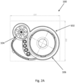
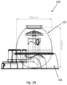
- FIGS. 2A to 2C there is illustrated the top, side and front view of an example embodiment of the container inflator system 100. These diagrams show the position of the inflator apparatus 104 and suction chamber 102 as well as the various storage compartments 108, 110. The diagrams also shown some example dimensions, which are provided for guidance only and would be appreciated by a person skilled in the art that the dimensions can vary, either with minor or significant variations.
- the dimensions of this example embodiment of the container inflator system 100 are approximately 250mm in length and 200mm wide.
- the container inflation system 100 may be of any dimensions, this example container inflator system 100 is intended to be relatively compact and is sized to be similar to that of a typical desk toy for children.
- This example embodiment would therefore illustrate the advantages in that the system 100 may be used by a child at home or by a user at a party venue, without the necessity of large or complex equipment to insert objects into a balloon to make a "stuffed" balloon.
- FIG. 3A is an exploded diagram of an example container inflator system 300, for the purposes of simplicity the various containers 108, 110 that are illustrated in the examples of Figures 1A to 2C are not shown.
- the suction chamber is formed by a base 316 and a suction chamber dome 312 which is placed over the base 316 so as to form the suction chamber.
- the suction chamber dome 312 is preferably sealed to the suction base 316 by screw fit and includes a rubber or soft seal 314 so to prevent suction pressure within the suction chamber to be lost through the engagement between the suction chamber dome 312 and the base 316.
- the base 316 preferably has an aperture disposed near towards its lowest point which is in turn connected to a fluid conduit, such as an air tube 318, which is in turn connected to a pumping system (304, 332, 330, 326, 320, 322, 324). The pumping system may then be able to provide suction pressure to the suction chamber.
- the aperture disposed near towards its lowest point of the suction chamber is also in communication with an annular slot (not shown) placed on the bottom of the base 316 such that the suction pressure may be evenly distributed around the chamber. This may be advantageous as the even distribution of suction pressure may ensure the balloon within the suction chamber can be expanded evenly around the suction chamber and not expanded to one side of the chamber.
- the inflation apparatus is placed adjacent to the suction chamber and includes a pumping system comprising of various pump related parts (304, 332, 330, 326, 320, 322, 324) that is placed within the inflation apparatus.
- the pumping system is a manual pumping system that includes a pump that comprises a pump piston 332, 330, within a pump cylinder 326 and a piston spring mechanism 320, 322 324 so as to allow the pump to create suction and inflation pressure for the inflation apparatus and the suction chamber, although as it will be appreciated, an electric pump system may also be implemented in some examples.
- the container inflator system 300 includes a delivery valve arrangement 302, 306, 310 arranged to facilitate the sealing and transfer of the balloon from the suction chamber for further inflation by the inflation apparatus.
- the delivery valve arrangement may include a one way valve 302 which is arranged to ensure air pressure can be inserted into the balloon whilst also ensuring that air pressure cannot escape from the balloon 328.
- the one way valve would in turn be engaged with a plurality of annular members, including a funnel 306, and optionally a cover (not shown), which is arranged to secure the valve 302 to the balloon 328.
- the annular members may also be removably engaged with the opening of the suction chamber thus allowing the balloon 328 to expand when it is secured to the suction chamber, and when desired, the delivery valve arrangement, together with the balloon 328, can be removed from the suction chamber.
- the annular members may be of a similar size to the opening of the suction chamber.
- the balloon 328 is firstly placed within the suction chamber with its opening being stretched around the opening of the suction chamber. This creates a seal around the suction chamber and thus allows the balloon 328 to be expanded when suction chamber is applied to the suction chamber.
- a hook annular member 310 similar to a ring, may be placed around the opening of the suction chamber dome 312.
- the annular member 310 has a plurality of soft and blunt hooks which help seat the balloons opening around the opening of the suction chamber dome 312.
- the user may insert the balloon 328 into the suction chamber, then proceed to stretch the balloon's opening around the opening of the suction chamber by stretching the opening of the balloon around the hooks of the hook annular member 310.
- the hooks in turn urge the engagement of the balloon 328 in position to prevent the balloon 328 from unintentional disengaging from the opening of the suction chamber.
- a fingered ring 308 which may be seated over the opening of the balloon and the suction chamber.
- the fingered ring 308 includes a plurality of flexible fingers which bends to allow various objects or items to be inserted into the balloon 328 when the balloon is inflated within the suction chamber.
- the ring 308, which can be removed when it is desirable to seal the balloon with the delivery valve, is arranged to protect the neck of the balloon 328 from scrapes or physical damage when objects or items are inserted into the balloon 328. This is particularly advantageous when larger or hard objects are inserted into the balloon such as soft toys or LED lights that have harder and sharper batteries or wiring circuits.
- the user can insert the delivery valve arrangement into the neck of the balloon 328, which at present has been stretched around the opening of the suction chamber.
- the flanged portions of the delivery valve is similar, although slightly smaller in size, to the opening of the suction chamber, the user can insert the delivery valve arrangement over the opening of the suction chamber with a near snug fit over the opening of the balloon.
- the near snug fit should be sufficiently loose so as not to damage the balloon 328, but should be preferably near the size of the stretched opening of the balloon 328 so as to facilitate an easy seal of the balloon 328.
- a soft or rubbery ring similar to an O-ring, can be used along the edges of the annular members 306 such that it can be inserted into the stretched opening of the balloon 328 to form a seal with the balloon 328, whilst also permitting it to travel through the opening of the suction chamber so that the balloon 328 can be removed from the chamber.
- the user may then further seal the balloon's opening to the delivery valve arrangement.
- This can be performed in various ways depending on a preferred implementation of the annular members 306 of the delivery valve arrangements.
- the O-ring of the valve will then form a seal with the stretched balloon 328.
- the user may then cover this seal with a cap (not shown) to secure the balloon to the O-ring so as to form a more secure seal of the balloon 328 to the valve 302.
- the user can remove the suction chamber dome 312 from the base 316, preferably, by rotating the suction chamber dome 312 away from the base 316 via its screw fit arrangement. Once removed, the user can push the delivery valve arrangement through the opening of the suction chamber dome 312, together with the balloon 328 which could now be freed from the suction chamber dome 312.
- the user may then further inflate the balloon 328 to a larger size by now inserting the delivery valve arrangement to the inflation apparatus adjacent to the suction chamber. Once inserted into inflation apparatus, the user can operate the pump to further inflate the balloon 328.
- the inflation apparatus includes a manual pumping system which has a piston 332, 330, pump cylinder 326 and spring unit 320, 322, 324.
- the pumping system is also connected to the inflation apparatus and the suction chamber with a valve arrangement 326V that includes a plurality of one way valves 326V such that suction pressure can be delivered to the suction chamber whilst inflation pressure can be directed to the inflation apparatus when the pump piston 332 is operated by a user.
- the balloon 328 can be disengaged from the delivery valve arrangement by firstly sealing the opening of the balloon 328. This may be performed by simply tying the portions of the balloon 328 adjacent to its opening, commonly the neck of a standard balloon, with a ribbon, string, or similar balloon sealing devices.
- the delivery valve arrangement may in turn be disengaged from the balloon 328 and may be used with another balloon.
- the present example embodiments of the container inflator system 100, 300 may be advantageous as it is able to assist users to make a "stuffed" balloon without complex equipment. Additionally, as the suction chamber and the inflation apparatus may be integrated into the same unit, the system 100, 300 may also be easy to use, compact to store and transport and low cost to manufacture. In turn, rendering the system 100, 300 practical as a domestic toy for children and adults.
Landscapes
- Toys (AREA)
Description
- The present invention relates to a container inflator system, and particularly, although not exclusively, to a container inflator system arranged to inflate balloons or the like so as to allow objects to be placed within.
- Balloons are a common toy which is enjoyed by children and adults alike. There are various versions of balloon toys including use of different materials to make the balloons, forming the balloon with different shapes or the use of lighter than air gases to inflate the balloons to create balloons that float in the atmosphere.
- Balloons are a common toy which is enjoyed by children and adults alike. There are various versions of balloon toys including use of different materials to make the balloons, forming the balloon with different shapes or the use of lighter than air gases to inflate the balloons to create balloons that float in the atmosphere.
- One recent trend has been to inflate balloons with different toys or decorative items so as to improve the appearance or enjoy-ability of the balloon. One such product is to insert decorative items within an inflated balloon such as LED lights or toys. These add to the interests of the balloons and can also change the effect of the balloon. Examples of such balloons may be to include festive lights into the balloon during Christmas, or romantic items such as flowers or rose pedals during Valentine's day, or the inclusion of soft toys for birthday parties.
- However, the manufacturing of such balloons is complicated by the difficulty in the insertion of items into a balloon followed by the correct inflation of the balloon. This process cannot be achieved with simple means as it is difficult to insert objects within a balloon without tearing the balloon itself. Accordingly, the creation of such balloons that houses various toys or objects within typically require specialist equipment that are large and expensive. In turn, such balloons are typically created by specialist toy, balloon or party stores.
US5088267A discloses a container inflator system according to the preamble of claim 1. - In accordance with a first aspect of the present invention, there is provided a container inflator system according to claim 1.
- In accordance with a second aspect of the present invention, there is provided a method for inflating a balloon according to claim 12.
- Embodiments of the present invention will now be described, by way of example, with reference to the accompanying drawings in which:
-
Figure 1A is an illustration of a container inflation system in accordance with one embodiment of the present invention; -
Figure 1B is an illustration of the container inflation system ofFigure 1A ; -
Figure 2A is a top view of the container inflation system ofFigure 1B ; -
Figure 2B is a side view of the container inflation system ofFigure 1B ; -
Figure 2C is a front view of the container inflation system ofFigure 1B ; -
Figure 3A is an exploded view of an example container inflation system; -
Figure 3B illustrates an example hook ring engaged to an opening aperture of an example suction chamber of one example embodiment of the container inflation system; -
Figure 3C illustrates a finger ring used with the opening aperture ofFigure 3B ; and, -
Figure 3D is a cut away view of the container inflation system ofFigure 3A . - Referring to
Figures 1A and1B , there is illustrated an example embodiment of a container inflator system comprising: - a suction chamber arranged to expand the container within the suction chamber whilst maintaining at least one opening for accessing the container; and,
- an inflation apparatus arranged to further inflate the container when the container is removed from the suction chamber.
- In this embodiment, the
container inflator system 100 includes asuction chamber 102, and aninflation apparatus 104 which operate together to allow a container, such as, but not limited to a balloon (not shown), to be inflated with objects or items placed therein. Such a balloon, once inflated with objects or items, may be referred to as a "stuffed" balloon. - In this example, the
suction chamber 102 is arranged to firstly expand a container such as a balloon, such that when it is expanded, the container's opening remains accessible for the insertion of objects therein. Once objects have been inserted into the container, the opening of the container may be sealed to prevent the inflating air pressure within the container to escape when it is released from thesuction chamber 102. Preferably this is performed by use of a delivery valve (not shown inFigures 1A and1B , but shown in one example with respect toFigures 3A to 3D ) arranged to seal the container so as to maintain the expanded state of the container when it is removed from thesuction chamber 102. - Once the container is removed from the
suction chamber 102, it can then be further inflated by placing the opening of the container into a position for fluid communication with aninflation apparatus 104. Theinflation apparatus 104 is then arranged to further inflate the container by delivering air pressure into the container so as to further expand the container. The delivery valve is arranged to be received and/or engage with theinflation apparatus 104 such that air pressure may be delivered to the container via the delivery valve so as to further inflate the container. - In examples where the container is a balloon, a user may firstly use the
suction chamber 102 to expand the balloon by use of suction pressure. The balloon may firstly be placed or inserted into thesuction chamber 102 with its opening being stretched around anannular opening 120 of thesuction chamber 102 so as to seal thesuction chamber 102 from the atmosphere. Once in this position, a user may then apply suction pressure to thesuction chamber 102 which is delivered preferably near thebase 106 of thesuction chamber 102 by a pumping device. In turn, the suction pressure causes the balloon to expand towards the walls of thesuction chamber 102 due to the vacuum created within thesuction chamber 102 and thus allowing the balloon to expand within thesuction chamber 102 so as to form a balloon chamber, a space within the expanded balloon. - Once formed, this balloon chamber can be filled with various objects such as toys, decorative items such as glitter dust, papers or strings, liquids, lights, plant materials, other balloons or any other items or objects that a user may desire to place within the balloon. Upon the completion of the insertion of objects within the balloon chamber, a user may then proceed to seal the balloon such that the balloon can retain the air pressure within it when the suction pressure or vacuum is removed from the
suction chamber 102. One possible method to perform this is by sealing the balloon with any sealing mechanism such as a ribbon or string tied around the balloon, or even by use of the user's digits. However, as it is undesirable to see that the balloon is deflated, since the items within may escape the balloon or may damage the internal walls of the balloon, a delivery valve is preferably used to seal the balloon. Description of an example embodiment of the delivery valve will be described below with reference toFigures 3A to 3D . - Once the balloon is sealed and the suction pressure is removed, the balloon can be removed from the
suction chamber 102 by disassembling the housing of thesuction chamber 102 away from thebase 106. In preferred examples, thesuction chamber 102 is formed by a dome shaped shell which is screw fitted into thebase 106. This dome shaped shell can be unscrewed from thebase 106 and thus allowing the balloon to be removed from thesuction chamber 102. Once the balloon is removed from thesuction chamber 102, the balloon may then be further inflated by delivering further inflation pressure to the balloon. This is preferable performed by theinflation apparatus 104 which in this example embodiment, as shown inFigures 1A to 3D is placed adjacent to thesuction chamber 102. The opening of the balloon is placed to engage with theinflation apparatus 104 so as to form a fluid communication between the balloon and theinflation apparatus 104. In turn, theinflation apparatus 104 is then operated by the user to deliver air pressure to the balloon. - As shown in this example embodiment, the
inflation apparatus 104 operates with a pumping device (not shown inFigures 1A and1B , but shown inFigures 3A and3D ) which also provides suction pressure to thesuction chamber 102. By use of a valve system having one or more one way valves, the pumping device is able to deliver both the suction pressure to thesuction chamber 102 and theinflation apparatus 104. This is advantageous as the usage of the same pumping device reduces the size and complexity of thecontainer inflator system 100 whilst also reducing the costs of manufacturing thesystem 100. - Preferably, and shown in
Figures 3A to 3D , an example of a removable delivery valve arrangement (302, 306) may be used to engage the balloon to thesuction chamber 102, The delivery valve arrangement may also seal the balloon when it is desired to remove the balloon from thesuction chamber 102 and may also allow further inflation pressure to be inserted within the balloon via theinflation apparatus 104. In this example, the removable delivery valve arrangement may also include a oneway valve 302 which permits air pressure to be inserted into the balloon, whilst preventing its escape from the balloon, and/or a plurality ofannular members 306 which assists to seal the balloon to the lip of the suction chamber's opening 120 whilst also allowing the balloon to be sealed to thevalve 302 when it is required to be removed from thesuction chamber 102. - The removable delivery valve arrangement is advantageous as a user can remove the balloon from the
suction chamber 102 without losing the air pressure within the balloon. Furthermore, in preferred examples where the valve is arranged to couple with theinflation apparatus 104, such as via anengagement nozzle 130 that engages the valve to theinflation apparatus 104, the valve also allows the user to further inflate the balloon with theinflation apparatus 104. Upon the balloons correct or desired inflation, a user may then remove the delivery valve arrangement by sealing the balloon at a position adjacent to the valve, such as the neck of the balloon adjacent to its opening. This can be performed by tying a ribbon or other forms of balloon seals around the balloon. In turn, releasing the valve arrangement for use with another balloon. - As shown in this example embodiment of
Figures 1A and1B , thesuction chamber 102 and theinflation apparatus 104 is placed adjacent to each other and is housed in these positions by ahousing base 106 which connects thechamber 102 to theinflation apparatus 104 to form a singlecontainer inflator device 100. As shown inFigures 1A and1B , thehousing 106 may also include one ormore storage compartments 108 for the storage of tools, balloons or other items. Preferably, as also shown, thehousing 106 may be moulded to include a plurality of cylindrical slots, each arranged to receive acylindrical container 110 to store various decorative materials. This is advantageous as thesecontainers 110 add to the overall aesthetics of thesystem 100 as well as provide the proper storage of decorative materials for use and ease of access by a user. - With reference to
Figures 2A to 2C , there is illustrated the top, side and front view of an example embodiment of thecontainer inflator system 100. These diagrams show the position of theinflator apparatus 104 andsuction chamber 102 as well as thevarious storage compartments - As illustrated, the dimensions of this example embodiment of the
container inflator system 100 are approximately 250mm in length and 200mm wide. In turn, although thecontainer inflation system 100 may be of any dimensions, this examplecontainer inflator system 100 is intended to be relatively compact and is sized to be similar to that of a typical desk toy for children. This example embodiment would therefore illustrate the advantages in that thesystem 100 may be used by a child at home or by a user at a party venue, without the necessity of large or complex equipment to insert objects into a balloon to make a "stuffed" balloon. - With reference to
Figures 3A to 3D , there are provided further illustrations of an examplecontainer inflator system 300 to illustrate the components of thesystem 300 in greater detail. As shown inFigure 3A , which is an exploded diagram of an examplecontainer inflator system 300, for the purposes of simplicity thevarious containers Figures 1A to 2C are not shown. - In this example embodiment, the suction chamber is formed by a
base 316 and asuction chamber dome 312 which is placed over the base 316 so as to form the suction chamber. Thesuction chamber dome 312 is preferably sealed to thesuction base 316 by screw fit and includes a rubber orsoft seal 314 so to prevent suction pressure within the suction chamber to be lost through the engagement between thesuction chamber dome 312 and thebase 316. The base 316 preferably has an aperture disposed near towards its lowest point which is in turn connected to a fluid conduit, such as anair tube 318, which is in turn connected to a pumping system (304, 332, 330, 326, 320, 322, 324). The pumping system may then be able to provide suction pressure to the suction chamber. It is also preferred that the aperture disposed near towards its lowest point of the suction chamber is also in communication with an annular slot (not shown) placed on the bottom of the base 316 such that the suction pressure may be evenly distributed around the chamber. This may be advantageous as the even distribution of suction pressure may ensure the balloon within the suction chamber can be expanded evenly around the suction chamber and not expanded to one side of the chamber. - In this example embodiment, the inflation apparatus is placed adjacent to the suction chamber and includes a pumping system comprising of various pump related parts (304, 332, 330, 326, 320, 322, 324) that is placed within the inflation apparatus. In this example, the pumping system is a manual pumping system that includes a pump that comprises a
pump piston pump cylinder 326 and apiston spring mechanism - As shown in this example, the
container inflator system 300 includes adelivery valve arrangement way valve 302 which is arranged to ensure air pressure can be inserted into the balloon whilst also ensuring that air pressure cannot escape from theballoon 328. The one way valve would in turn be engaged with a plurality of annular members, including afunnel 306, and optionally a cover (not shown), which is arranged to secure thevalve 302 to theballoon 328. Preferably, the annular members may also be removably engaged with the opening of the suction chamber thus allowing theballoon 328 to expand when it is secured to the suction chamber, and when desired, the delivery valve arrangement, together with theballoon 328, can be removed from the suction chamber. - In such an example arrangement, the annular members may be of a similar size to the opening of the suction chamber. Thus the
balloon 328 is firstly placed within the suction chamber with its opening being stretched around the opening of the suction chamber. This creates a seal around the suction chamber and thus allows theballoon 328 to be expanded when suction chamber is applied to the suction chamber. - As shown in this example and in
Figure 3B , a hookannular member 310 similar to a ring, may be placed around the opening of thesuction chamber dome 312. Preferably, theannular member 310 has a plurality of soft and blunt hooks which help seat the balloons opening around the opening of thesuction chamber dome 312. Thus in this example, the user may insert theballoon 328 into the suction chamber, then proceed to stretch the balloon's opening around the opening of the suction chamber by stretching the opening of the balloon around the hooks of the hookannular member 310. The hooks in turn urge the engagement of theballoon 328 in position to prevent theballoon 328 from unintentional disengaging from the opening of the suction chamber. - Optionally, also shown in
Figure 3C , is afingered ring 308 which may be seated over the opening of the balloon and the suction chamber. Thefingered ring 308 includes a plurality of flexible fingers which bends to allow various objects or items to be inserted into theballoon 328 when the balloon is inflated within the suction chamber. Thering 308, which can be removed when it is desirable to seal the balloon with the delivery valve, is arranged to protect the neck of theballoon 328 from scrapes or physical damage when objects or items are inserted into theballoon 328. This is particularly advantageous when larger or hard objects are inserted into the balloon such as soft toys or LED lights that have harder and sharper batteries or wiring circuits. - After a user inserts various objects or items into the expanded balloon sitting within the suction chamber, the user can insert the delivery valve arrangement into the neck of the
balloon 328, which at present has been stretched around the opening of the suction chamber. As the flanged portions of the delivery valve is similar, although slightly smaller in size, to the opening of the suction chamber, the user can insert the delivery valve arrangement over the opening of the suction chamber with a near snug fit over the opening of the balloon. The near snug fit should be sufficiently loose so as not to damage theballoon 328, but should be preferably near the size of the stretched opening of theballoon 328 so as to facilitate an easy seal of theballoon 328. Preferably, a soft or rubbery ring, similar to an O-ring, can be used along the edges of theannular members 306 such that it can be inserted into the stretched opening of theballoon 328 to form a seal with theballoon 328, whilst also permitting it to travel through the opening of the suction chamber so that theballoon 328 can be removed from the chamber. - When the delivery valve arrangement is inserted into the stretched opening of the
balloon 328, the user may then further seal the balloon's opening to the delivery valve arrangement. This can be performed in various ways depending on a preferred implementation of theannular members 306 of the delivery valve arrangements. Preferable, in the above example, when the user inserts the delivery valve arrangement, the O-ring of the valve will then form a seal with the stretchedballoon 328. The user may then cover this seal with a cap (not shown) to secure the balloon to the O-ring so as to form a more secure seal of theballoon 328 to thevalve 302. Once secured, the user can remove thesuction chamber dome 312 from thebase 316, preferably, by rotating thesuction chamber dome 312 away from thebase 316 via its screw fit arrangement. Once removed, the user can push the delivery valve arrangement through the opening of thesuction chamber dome 312, together with theballoon 328 which could now be freed from thesuction chamber dome 312. - The user may then further inflate the
balloon 328 to a larger size by now inserting the delivery valve arrangement to the inflation apparatus adjacent to the suction chamber. Once inserted into inflation apparatus, the user can operate the pump to further inflate theballoon 328. The inflation apparatus, as shown in this example, includes a manual pumping system which has apiston pump cylinder 326 andspring unit valve arrangement 326V that includes a plurality of oneway valves 326V such that suction pressure can be delivered to the suction chamber whilst inflation pressure can be directed to the inflation apparatus when thepump piston 332 is operated by a user. - Once the
balloon 328 has been inflated to a suitable air pressure, theballoon 328 can be disengaged from the delivery valve arrangement by firstly sealing the opening of theballoon 328. This may be performed by simply tying the portions of theballoon 328 adjacent to its opening, commonly the neck of a standard balloon, with a ribbon, string, or similar balloon sealing devices. The delivery valve arrangement may in turn be disengaged from theballoon 328 and may be used with another balloon. - The present example embodiments of the
container inflator system system system - It will be appreciated by persons skilled in the art that numerous variations and/or modifications may be made to the invention as shown in the specific embodiments without departing from the scope of the invention as defined by the appended claims. The present embodiments are, therefore, to be considered in all respects as illustrative and not restrictive.
- Any reference to prior art contained herein is not to be taken as an admission that the information is common general knowledge, unless otherwise indicated.
Claims (15)
- A container inflator system (100) comprising:- a suction chamber (102) arranged to expand the container within the suction chamber whilst maintaining at least one opening for accessing the container; and- an inflation apparatus (104) arranged to further inflate the container when the container is removed from the suction chamber (102);wherein the inflation apparatus (104) and the suction chamber (102) are operated by a pumping device;characterised in that the system (100) further comprises a delivery valve arranged to seal the container so as to maintain the expanded state of the container when it is removed from the suction chamber (102), wherein the delivery valve is arranged to couple with the pumping device to inflate the container.
- The container inflator system (100) in accordance with claim 1, wherein the pumping device includes a valve arrangement arranged to deliver suction pressure to the suction chamber.
- The container inflator system (100) in accordance with claim 1 or claim 2, wherein the valve arrangement is further arranged to deliver inflation pressure to the inflation apparatus (104).
- The container inflator system (100) in accordance with claim 3, wherein the valve arrangement includes a plurality of one way valves arranged to create the suction pressure and the inflation pressure when the pumping device is actuated.
- The container inflator system (100) in accordance with claim 4, wherein the pumping device includes a cylinder connected to the valve arrangement.
- The container inflator system (100) in accordance with claim 5, wherein the plurality of one way valves are arranged such that the suction pressure and the inflation pressure is created on a stroke of a piston of the cylinder.
- The container inflator system (100) in accordance with claim 6, wherein the suction chamber (102) is defined by a dome member arranged to be engaged to a base portion.
- The container inflator system (100) in accordance with claim 7, wherein the base portion is part of a base member arranged to engage with the inflation apparatus (104).
- The container inflator system (100) in accordance with any one of claims 1 to 8, wherein the delivery valve includes a one way valve.
- The container inflator system (100) in accordance with claim 9, wherein the one way valve is engaged to an annular member arranged to couple with the container.
- The container inflator system (100) in accordance with any one of claims 1 to 10, wherein the container is a balloon.
- A method for inflating a balloon comprising the steps of:- expanding a balloon by using suction pressure; and,- further inflating the balloon by delivering inflation pressure to the balloon, wherein the suction pressure and the inflation pressure are provided by a pumping device;- sealing the balloon after the balloon is expanded by the suction pressure, wherein the sealing of the balloon is performed by a delivery valve;wherein the delivery valve is arranged to couple with the pumping device to inflate the balloon.
- The method for inflating a balloon in accordance with claim 12, wherein the pumping device includes a valve arrangement arranged to direct suction pressure to the balloon and inflation pressure to the balloon.
- The method for inflating a balloon in accordance with claim 12 or claim 13, further including a step of inserting objects into the balloon.
- The method for inflating a balloon in accordance with any one of claims 12 to 14, wherein the step of inserting objects into the balloon is performed after the balloon is expanded by suction pressure.
Applications Claiming Priority (2)
| Application Number | Priority Date | Filing Date | Title |
|---|---|---|---|
| CN201911150523.3A CN112823836A (en) | 2019-11-21 | 2019-11-21 | Container inflation system and method of balloon inflation |
| PCT/CN2019/127568 WO2021098001A1 (en) | 2019-11-21 | 2019-12-23 | A container inflator system and a method for inflating a balloon |
Publications (5)
| Publication Number | Publication Date |
|---|---|
| EP4061503A1 EP4061503A1 (en) | 2022-09-28 |
| EP4061503A4 EP4061503A4 (en) | 2024-01-03 |
| EP4061503B1 true EP4061503B1 (en) | 2025-05-21 |
| EP4061503C0 EP4061503C0 (en) | 2025-05-21 |
| EP4061503B8 EP4061503B8 (en) | 2025-08-06 |
Family
ID=75907536
Family Applications (1)
| Application Number | Title | Priority Date | Filing Date |
|---|---|---|---|
| EP19953582.4A Active EP4061503B8 (en) | 2019-11-21 | 2019-12-23 | A container inflator system and a method for inflating a balloon |
Country Status (5)
| Country | Link |
|---|---|
| US (1) | US12214291B2 (en) |
| EP (1) | EP4061503B8 (en) |
| CN (1) | CN112823836A (en) |
| ES (1) | ES3037639T3 (en) |
| WO (1) | WO2021098001A1 (en) |
Families Citing this family (2)
| Publication number | Priority date | Publication date | Assignee | Title |
|---|---|---|---|---|
| WO2025152152A1 (en) * | 2024-01-19 | 2025-07-24 | Boti Global Limited | Container inflation system and a method of inflating a balloon using thereof |
| CN120132368A (en) * | 2025-04-08 | 2025-06-13 | 宁波恒颖玩具实业有限公司 | Balloon Inflator |
Family Cites Families (11)
| Publication number | Priority date | Publication date | Assignee | Title |
|---|---|---|---|---|
| US4809483A (en) * | 1988-02-12 | 1989-03-07 | Lovik Craig J | Low cost balloon stuffing system |
| US4974393A (en) * | 1989-03-21 | 1990-12-04 | Maxim Marketing, Inc. | Apparatus and method for inserting objects into balloons |
| US5088267A (en) * | 1989-08-25 | 1992-02-18 | Gee Anthony L | Apparatus and methods for placing an object inside an inflated balloon |
| US5205109A (en) * | 1991-12-23 | 1993-04-27 | Conway Matthew J | Method and apparatus for expanding a balloon and accessing the interior thereof |
| US5370161A (en) * | 1993-07-06 | 1994-12-06 | Shafer; Erik J. | Balloon vending machine |
| US6141941A (en) * | 1999-03-15 | 2000-11-07 | Carroll; William Gregory | Apparatus and method for inserting objects into balloons |
| KR100860724B1 (en) * | 2004-06-05 | 2008-09-29 | 푸 뉴엔 | Devices for sealing and lighting balloons |
| US8292454B2 (en) * | 2004-11-12 | 2012-10-23 | Chemical Light, Inc. | Externally switchable illuminated balloon inflator |
| CN204107049U (en) * | 2014-09-29 | 2015-01-21 | 傅裕 | Balloon toy |
| US20180066641A1 (en) * | 2016-09-08 | 2018-03-08 | Moose Creative Management Pty Limited | Inflatable toy and inflation device |
| CN212067740U (en) * | 2019-11-21 | 2020-12-04 | 博梯环球有限公司 | Container inflation system |
-
2019
- 2019-11-21 CN CN201911150523.3A patent/CN112823836A/en active Pending
- 2019-12-23 EP EP19953582.4A patent/EP4061503B8/en active Active
- 2019-12-23 ES ES19953582T patent/ES3037639T3/en active Active
- 2019-12-23 US US17/775,055 patent/US12214291B2/en active Active
- 2019-12-23 WO PCT/CN2019/127568 patent/WO2021098001A1/en not_active Ceased
Also Published As
| Publication number | Publication date |
|---|---|
| EP4061503A1 (en) | 2022-09-28 |
| CN112823836A (en) | 2021-05-21 |
| US20220387901A1 (en) | 2022-12-08 |
| EP4061503B8 (en) | 2025-08-06 |
| US12214291B2 (en) | 2025-02-04 |
| WO2021098001A1 (en) | 2021-05-27 |
| ES3037639T3 (en) | 2025-10-03 |
| EP4061503C0 (en) | 2025-05-21 |
| EP4061503A4 (en) | 2024-01-03 |
Similar Documents
| Publication | Publication Date | Title |
|---|---|---|
| AU603283B2 (en) | Balloon stuffing system | |
| EP0453445A4 (en) | Apparatus and method of filling a balloon with articles and air | |
| US4226902A (en) | Decorative device | |
| US4809483A (en) | Low cost balloon stuffing system | |
| US6478651B1 (en) | Inflatable balloon bouquet | |
| US12214291B2 (en) | Container inflator system and a method for inflating a balloon | |
| CA2544412A1 (en) | Visual display and method of providing a visual display | |
| US10105615B2 (en) | System and method fluid transfer between inflatable objects | |
| GB2042136A (en) | Inflation valve | |
| US20080090487A1 (en) | Inflatable plastic articles with sealed internal illumination | |
| US5033256A (en) | Balloon filler | |
| US20070062970A1 (en) | Dispensing apparatus for disposable gloves or like | |
| US20040198150A1 (en) | Valve and retainer for latex balloons | |
| CN212067740U (en) | Container inflation system | |
| US4878335A (en) | Methods and apparatus for inserting objects within balloons | |
| US7931402B1 (en) | Inflatable gift wrap in the shape of a cake | |
| US5205109A (en) | Method and apparatus for expanding a balloon and accessing the interior thereof | |
| US20120298229A1 (en) | Inflatable shape maintenance device for a handbag or purse | |
| US5088267A (en) | Apparatus and methods for placing an object inside an inflated balloon | |
| US20080064541A1 (en) | Inflatable play ball | |
| WO2025152152A1 (en) | Container inflation system and a method of inflating a balloon using thereof | |
| WO2007091083A1 (en) | Balloon inflation system | |
| WO2006081187A1 (en) | Valve and retainer assembly for latex balloons | |
| WO2003009916A1 (en) | Interlocking balloons | |
| TW200518814A (en) | Inflatable plush toy |
Legal Events
| Date | Code | Title | Description |
|---|---|---|---|
| STAA | Information on the status of an ep patent application or granted ep patent |
Free format text: STATUS: THE INTERNATIONAL PUBLICATION HAS BEEN MADE |
|
| PUAI | Public reference made under article 153(3) epc to a published international application that has entered the european phase |
Free format text: ORIGINAL CODE: 0009012 |
|
| STAA | Information on the status of an ep patent application or granted ep patent |
Free format text: STATUS: REQUEST FOR EXAMINATION WAS MADE |
|
| 17P | Request for examination filed |
Effective date: 20220527 |
|
| AK | Designated contracting states |
Kind code of ref document: A1 Designated state(s): AL AT BE BG CH CY CZ DE DK EE ES FI FR GB GR HR HU IE IS IT LI LT LU LV MC MK MT NL NO PL PT RO RS SE SI SK SM TR |
|
| DAV | Request for validation of the european patent (deleted) | ||
| DAX | Request for extension of the european patent (deleted) | ||
| A4 | Supplementary search report drawn up and despatched |
Effective date: 20231201 |
|
| RIC1 | Information provided on ipc code assigned before grant |
Ipc: A63H 27/10 20060101AFI20231127BHEP |
|
| GRAP | Despatch of communication of intention to grant a patent |
Free format text: ORIGINAL CODE: EPIDOSNIGR1 |
|
| STAA | Information on the status of an ep patent application or granted ep patent |
Free format text: STATUS: GRANT OF PATENT IS INTENDED |
|
| INTG | Intention to grant announced |
Effective date: 20241210 |
|
| GRAS | Grant fee paid |
Free format text: ORIGINAL CODE: EPIDOSNIGR3 |
|
| GRAA | (expected) grant |
Free format text: ORIGINAL CODE: 0009210 |
|
| STAA | Information on the status of an ep patent application or granted ep patent |
Free format text: STATUS: THE PATENT HAS BEEN GRANTED |
|
| AK | Designated contracting states |
Kind code of ref document: B1 Designated state(s): AL AT BE BG CH CY CZ DE DK EE ES FI FR GB GR HR HU IE IS IT LI LT LU LV MC MK MT NL NO PL PT RO RS SE SI SK SM TR |
|
| RAP3 | Party data changed (applicant data changed or rights of an application transferred) |
Owner name: BOTI GLOBAL LIMITED |
|
| REG | Reference to a national code |
Ref country code: GB Ref legal event code: FG4D |
|
| REG | Reference to a national code |
Ref country code: CH Ref legal event code: EP |
|
| REG | Reference to a national code |
Ref country code: DE Ref legal event code: R096 Ref document number: 602019070442 Country of ref document: DE |
|
| REG | Reference to a national code |
Ref country code: IE Ref legal event code: FG4D |
|
| GRAT | Correction requested after decision to grant or after decision to maintain patent in amended form |
Free format text: ORIGINAL CODE: EPIDOSNCDEC |
|
| REG | Reference to a national code |
Ref country code: CH Ref legal event code: PK Free format text: BERICHTIGUNG B8 |
|
| U01 | Request for unitary effect filed |
Effective date: 20250620 |
|
| RAP4 | Party data changed (patent owner data changed or rights of a patent transferred) |
Owner name: BOTI GLOBAL LIMITED |
|
| U07 | Unitary effect registered |
Designated state(s): AT BE BG DE DK EE FI FR IT LT LU LV MT NL PT RO SE SI Effective date: 20250806 |
|
| REG | Reference to a national code |
Ref country code: ES Ref legal event code: FG2A Ref document number: 3037639 Country of ref document: ES Kind code of ref document: T3 Effective date: 20251003 |
|
| PG25 | Lapsed in a contracting state [announced via postgrant information from national office to epo] |
Ref country code: NO Free format text: LAPSE BECAUSE OF FAILURE TO SUBMIT A TRANSLATION OF THE DESCRIPTION OR TO PAY THE FEE WITHIN THE PRESCRIBED TIME-LIMIT Effective date: 20250821 Ref country code: GR Free format text: LAPSE BECAUSE OF FAILURE TO SUBMIT A TRANSLATION OF THE DESCRIPTION OR TO PAY THE FEE WITHIN THE PRESCRIBED TIME-LIMIT Effective date: 20250822 |
|
| PG25 | Lapsed in a contracting state [announced via postgrant information from national office to epo] |
Ref country code: PL Free format text: LAPSE BECAUSE OF FAILURE TO SUBMIT A TRANSLATION OF THE DESCRIPTION OR TO PAY THE FEE WITHIN THE PRESCRIBED TIME-LIMIT Effective date: 20250521 |
|
| PG25 | Lapsed in a contracting state [announced via postgrant information from national office to epo] |
Ref country code: HR Free format text: LAPSE BECAUSE OF FAILURE TO SUBMIT A TRANSLATION OF THE DESCRIPTION OR TO PAY THE FEE WITHIN THE PRESCRIBED TIME-LIMIT Effective date: 20250521 |
|
| PG25 | Lapsed in a contracting state [announced via postgrant information from national office to epo] |
Ref country code: RS Free format text: LAPSE BECAUSE OF FAILURE TO SUBMIT A TRANSLATION OF THE DESCRIPTION OR TO PAY THE FEE WITHIN THE PRESCRIBED TIME-LIMIT Effective date: 20250821 |
|
| PG25 | Lapsed in a contracting state [announced via postgrant information from national office to epo] |
Ref country code: IS Free format text: LAPSE BECAUSE OF FAILURE TO SUBMIT A TRANSLATION OF THE DESCRIPTION OR TO PAY THE FEE WITHIN THE PRESCRIBED TIME-LIMIT Effective date: 20250921 |
|
| PGFP | Annual fee paid to national office [announced via postgrant information from national office to epo] |
Ref country code: GB Payment date: 20251229 Year of fee payment: 7 |
|
| PG25 | Lapsed in a contracting state [announced via postgrant information from national office to epo] |
Ref country code: SM Free format text: LAPSE BECAUSE OF FAILURE TO SUBMIT A TRANSLATION OF THE DESCRIPTION OR TO PAY THE FEE WITHIN THE PRESCRIBED TIME-LIMIT Effective date: 20250521 |
|
| PG25 | Lapsed in a contracting state [announced via postgrant information from national office to epo] |
Ref country code: CZ Free format text: LAPSE BECAUSE OF FAILURE TO SUBMIT A TRANSLATION OF THE DESCRIPTION OR TO PAY THE FEE WITHIN THE PRESCRIBED TIME-LIMIT Effective date: 20250521 |
|
| U20 | Renewal fee for the european patent with unitary effect paid |
Year of fee payment: 7 Effective date: 20251215 |
|
| PG25 | Lapsed in a contracting state [announced via postgrant information from national office to epo] |
Ref country code: SK Free format text: LAPSE BECAUSE OF FAILURE TO SUBMIT A TRANSLATION OF THE DESCRIPTION OR TO PAY THE FEE WITHIN THE PRESCRIBED TIME-LIMIT Effective date: 20250521 |
|
| PLBE | No opposition filed within time limit |
Free format text: ORIGINAL CODE: 0009261 |
|
| STAA | Information on the status of an ep patent application or granted ep patent |
Free format text: STATUS: NO OPPOSITION FILED WITHIN TIME LIMIT |
|
| REG | Reference to a national code |
Ref country code: CH Ref legal event code: L10 Free format text: ST27 STATUS EVENT CODE: U-0-0-L10-L00 (AS PROVIDED BY THE NATIONAL OFFICE) Effective date: 20260402 |
|
| PGFP | Annual fee paid to national office [announced via postgrant information from national office to epo] |
Ref country code: ES Payment date: 20260122 Year of fee payment: 7 |
|
| 26N | No opposition filed |
Effective date: 20260224 |