EP4061295B1 - Portable urine collection system and related method - Google Patents
Portable urine collection system and related method Download PDFInfo
- Publication number
- EP4061295B1 EP4061295B1 EP20817592.7A EP20817592A EP4061295B1 EP 4061295 B1 EP4061295 B1 EP 4061295B1 EP 20817592 A EP20817592 A EP 20817592A EP 4061295 B1 EP4061295 B1 EP 4061295B1
- Authority
- EP
- European Patent Office
- Prior art keywords
- urine collection
- conduit
- pump
- urine
- container
- Prior art date
- Legal status (The legal status is an assumption and is not a legal conclusion. Google has not performed a legal analysis and makes no representation as to the accuracy of the status listed.)
- Active
Links
Images

Classifications
-
- A—HUMAN NECESSITIES
- A61—MEDICAL OR VETERINARY SCIENCE; HYGIENE
- A61F—FILTERS IMPLANTABLE INTO BLOOD VESSELS; PROSTHESES; DEVICES PROVIDING PATENCY TO, OR PREVENTING COLLAPSING OF, TUBULAR STRUCTURES OF THE BODY, e.g. STENTS; ORTHOPAEDIC, NURSING OR CONTRACEPTIVE DEVICES; FOMENTATION; TREATMENT OR PROTECTION OF EYES OR EARS; BANDAGES, DRESSINGS OR ABSORBENT PADS; FIRST-AID KITS
- A61F5/00—Orthopaedic methods or devices for non-surgical treatment of bones or joints; Nursing devices ; Anti-rape devices
- A61F5/44—Devices worn by the patient for reception of urine, faeces, catamenial or other discharge; Colostomy devices
- A61F5/451—Genital or anal receptacles
-
- A—HUMAN NECESSITIES
- A61—MEDICAL OR VETERINARY SCIENCE; HYGIENE
- A61F—FILTERS IMPLANTABLE INTO BLOOD VESSELS; PROSTHESES; DEVICES PROVIDING PATENCY TO, OR PREVENTING COLLAPSING OF, TUBULAR STRUCTURES OF THE BODY, e.g. STENTS; ORTHOPAEDIC, NURSING OR CONTRACEPTIVE DEVICES; FOMENTATION; TREATMENT OR PROTECTION OF EYES OR EARS; BANDAGES, DRESSINGS OR ABSORBENT PADS; FIRST-AID KITS
- A61F5/00—Orthopaedic methods or devices for non-surgical treatment of bones or joints; Nursing devices ; Anti-rape devices
- A61F5/44—Devices worn by the patient for reception of urine, faeces, catamenial or other discharge; Colostomy devices
- A61F5/4404—Details or parts
- A61F5/4408—Means for securing receptacles or bags to the body otherwise than by adhesives, e.g. belts, straps or harnesses
-
- A—HUMAN NECESSITIES
- A61—MEDICAL OR VETERINARY SCIENCE; HYGIENE
- A61B—DIAGNOSIS; SURGERY; IDENTIFICATION
- A61B5/00—Measuring for diagnostic purposes; Identification of persons
- A61B5/20—Measuring for diagnostic purposes; Identification of persons for measuring urological functions restricted to the evaluation of the urinary system
- A61B5/207—Sensing devices adapted to collect urine
-
- A—HUMAN NECESSITIES
- A61—MEDICAL OR VETERINARY SCIENCE; HYGIENE
- A61F—FILTERS IMPLANTABLE INTO BLOOD VESSELS; PROSTHESES; DEVICES PROVIDING PATENCY TO, OR PREVENTING COLLAPSING OF, TUBULAR STRUCTURES OF THE BODY, e.g. STENTS; ORTHOPAEDIC, NURSING OR CONTRACEPTIVE DEVICES; FOMENTATION; TREATMENT OR PROTECTION OF EYES OR EARS; BANDAGES, DRESSINGS OR ABSORBENT PADS; FIRST-AID KITS
- A61F5/00—Orthopaedic methods or devices for non-surgical treatment of bones or joints; Nursing devices ; Anti-rape devices
- A61F5/44—Devices worn by the patient for reception of urine, faeces, catamenial or other discharge; Colostomy devices
- A61F5/4404—Details or parts
- A61F5/4405—Valves or valve arrangements specially adapted therefor ; Fluid inlets or outlets
Definitions
- An individual may have limited or impaired mobility such that typical urination processes are challenging or impossible. For example, the individual may have had surgery or may have a disability that impairs mobility. In another example, the individual may have restricted travel conditions such as those experienced by pilots, drivers, and workers in hazardous areas. Additionally, fluid collection from the individual may be needed for monitoring purposes or clinical testing.
- Bed pans and urinary catheters such as a Foley catheter, may be used to address some of these circumstances.
- bed pans and urinary catheters have several problems associated therewith.
- bed pans may be prone to discomfort, spills, and other hygiene issues.
- Urinary catheters be may be uncomfortable, painful, and may cause urinary tract infections.
- a portable urine collection system includes a urine collection device, a first conduit, a urine collection bag having an interior region, a second conduit, and a modular pump.
- the urine collection device is configured to be positioned at least proximate to a urethra of a user.
- the first conduit is in fluid communication with the fluid collection device.
- the second conduit is in fluid communication with the interior region of the urine collection bag.
- the modular pump is configured to pull a vacuum and draw urine from the urine collection device through the first conduit and force the urine through the second conduit into the interior region of the urine collection bag.
- a method of assembling a portable urine collection system includes connecting a first conduit to a urine collection device to provide fluid communication between the urine collection device and the first conduit.
- the method also includes connecting a second conduit to a urine collection bag to provide fluid communication between the second conduit and the urine collection bag.
- the method also includes connecting a modular pump to the first conduit and the second conduit, the modular pump configured to pull a vacuum and draw urine from the urine collection device through the first conduit and force the urine through the second conduit into the urine collection bag.
- the method also includes, after collecting at least some urine from the urine collection device in the urine collection bag, replacing at least one of the first conduit, the second conduit, the urine collection device, the urine collection bag, and/or the modular pump with a different first conduit, a different second conduit, a different urine collection bag, a different urine collection device, and/or a different modular pump.
- a portable urine collection system which includes a container including an interior region, a modular pump in fluid communication with the interior region, and a backpack.
- the modular pump is configured to pull a vacuum and draw urine from a urine collection device positioned proximate to a urethra of a user into the interior region of the chamber.
- the backpack is configured to be worn by the user and sized and dimensioned to hold the container and the modular pump therein when being worn by the user.
- the devices and systems disclosed herein are configured to collect fluids from an individual.
- the fluids collected by the fluid collection devices may include at least one of urine, vaginal discharge, penile discharge, reproductive fluids, blood, sweat, or other bodily fluids.
- Conventional urine collection systems are typically designed for patients confined to a bed and, accordingly, typically have a fixed architecture including a urine collection device, a conduit, a urine collection container, and a pump.
- a pump of the urine collection system if a pump of the urine collection system is no longer functional, additional elements of the urine collection system may also need to be replaced in addition to the pump.
- conventional urine collection systems may also be limited to and/or compatible with a single type or size of pump, and a user or caregiver is prohibited from interchanging the pump with a different pump to meet the needs of the user or certain circumstances.
- Embodiments of the invention presented herein include a modular architecture that allows one or more components to be replaced by a similar component or a component having features desired for specific activities or a specific user.
- the one or more components may be configured for replacement by an end user after an original component has been used, malfunctions, or does not operate with the end user as desired.
- a female urine collection device may be removed and replaced with a male urine collection device, a smaller urine collection device can be replaced with a larger urine collection device, a smaller power source can be replaced with a larger power source, one pump can be replaced with another pump, a dysfunctional pump or power source can be replaced with a functioning pump or power source, a soiled or kinked conduit can be replaced with a clean conduit, a soiled urine collection device can be replaced with a clean urine collection device, and so on.
- Embodiments of modular urine collection systems described herein also allow a user to reuse one or more of the pump, the power source (e.g., battery), the controller, or the three-way valves, while one or more of the urine collection device, the conduit, or the collection bag may be disposable.
- a disposable device such as a disposable modular pump, includes a device that may be manually disconnected from the system by a user or caregiver without damaging the remaining system, and then placed in the garbage or rubbish bin.
- the one or more components may be replaced with different components by the user at the convenience or preference of the user. Connectors between modular components are universal, allowing each component to be replaced with a suitable counterpart.
- Conventional urine collection systems may be sized and dimensioned for a user to use the conventional urine collection system in bed next to a wall-mounted power source but nowhere else.
- incontinent ambulatory users have need for a urine collection system that allows them to carry about more normal activities without the embarrassment of soiling his/her clothes.
- the modular architecture of the urine collection systems described herein also may be portable by the user or caregiver without assistance of a motorized vehicle.
- a portable urine collection system is sized, dimensioned, and weighted to allow a user or caregiver to carry the entire urine collection system with, for example, only the assistance of a backpack and/or a sleeve.
- the portable and modular architecture of urine collection systems described herein also allows the patient or end user to use the system in a variety of settings, such as a wheelchair or ambulatory.
- the pump, the battery, and the fluid collection bag are sized and dimensioned to be simultaneously carried by the user when the urine collection device is positioned at least proximate to the urethra of the user.
- the pump and the power supply are sized and dimensioned to be detachably secured proximate to a waist of the user and the urine collection bag is sized and dimensioned to be positioned within a pocket of a leg sleeve worn on the leg of the user.
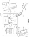
- FIG. 1 is a block diagram of a portable urine collection system 100.
- the urine collection system 100 includes a urine collection device 102, a first conduit 104, a container 108, a pump 110, a second conduit 118, a collection bag 120, a controller 122, and a power supply 124. While the urine collection device 102 shown in FIG. 1 includes a female urine collection device, the urine collection device 102 may instead include a male urine collection device.
- PCT International Application No. PCT/US2019/029616 describes various embodiments of both male and female fluid collection devices. Moreover, the urine collection device 102 may be interchangeable in the urine collection system 100 between different types, varieties, and sizes of male or female urine collection devices.
- the urine collection device 102 is configured to be positioned proximate or adjacent to a urethra of a user.
- the urine collection device 102 may include a surface sized to be positioned proximate or adjacent to the urethra and configured to wick urine or other fluids away from the user. Urine or other fluids may be wicked from the surface to a reservoir in the urine collection device 102.
- the urine collection system 100 also includes a first conduit 104.
- the first conduit 104 is configured to provide fluid communication between the pump 110 and the urine collection device 102, and may include a flexible tube.
- the fluid collection device 102 includes a connector 126 configured to connect to the first conduit 104.
- the fluid collection device 102 also may include an additional conduit 128 connecting the connector 126 and the body of the fluid collection device 102.
- the additional conduit 128 may provide fluid communication with the reservoir of the urine collection device 102 or an interior portion of the urine collection device 102 to allow urine to be withdrawn from the urine collection device 102 through the additional conduit 128. When connected, the additional conduit 128 provides fluid communication between the first conduit 104 and the urine collection device 102.
- the first conduit 104 may connect directly to the urine collection device 102 to provide fluid communication with the reservoir of the urine collection device 102 or an interior portion of the urine collection device 102 to allow urine to be withdrawn from the urine collection device through the first conduit 104.
- the urine collection system 100 also includes a container 108 that may be generally rigid.
- the container 108 may be more rigid than the collection bag.
- a generally rigid container 108 of this disclosure is configured to hold its shape under the vacuum and positive pressures exerted by the pump 110.
- the container 108 is sized to hold a smaller volume of fluid or air than the collection bag 120.
- the container 108 may be sized to hold less than 500 mL of fluid or air, while the collection bag 120 may be sized to hold at least 1000 mL of fluid or air.
- the container 108 may be sized to hold about 200 mL to about 400 mL of fluid or air and the collection bag 120 may be sized to hold at least about 1000 mL or at least about 1500 mL of fluid or air.
- the first conduit 104 is connected to the container 108.
- the urine collection system 100 also may include a first check valve 106 providing fluid communication from the first conduit 104 into the container 108, while preventing fluid communication from the container 108 into the first conduit 104.
- a vacuum formed in the container 108 may pull a vacuum on the first conduit 104, thereby pulling fluid from at least one of the first conduit 104 or the urine collection device 102 and into the container 108.
- the first check valve 106 also may prevent fluid collected in the container 108 from passing through the first check valve 106 into the first conduit 104.
- the container 108 also is connected to the second conduit 118.
- the urine collection system 100 may include a second check valve 116 providing fluid communication from the container 108 into the second conduit 118, while preventing fluid communication from the second conduit 118 into the container 108.
- the second check valve 116 may prevent fluid communication from the second conduit 118 into the container 108, thereby preventing any fluids in the second conduit 118 or the collection bag 120 from passing through the second check valve 116 and entering the container 108.
- the second check valve 116 may provide fluid communication from the container 108 into the second conduit 118, thereby forcing fluid in the container 108 through the second check valve 116 into the second conduit 118 and into the collection bag 120.
- the second conduit 118 may be connected to the container 108 and configured to provide fluid communication between the container 108 and the collection bag 120 when the predetermined positive pressure is formed in the container 108 to force fluid in the container 108 through the second check valve 116 into the second conduit 118.
- the second conduit 118 may include a flexible tube.
- the second conduit 118 may be connected directly to the collection bag 120.
- the second conduit 118 is connected to a connector that is connected to the collection bag 120.
- An additional conduit may connect the connector to the collection bag 120.
- the additional conduit may provide fluid communication with an interior portion of the collection bag 120 to allow urine to be forced through the second conduit 118 into the collection bag 120. When connected, the additional conduit provides fluid communication between the second conduit 118 and the collection bag 120.
- the collection bag 120 may be a collapsible or expandable bag sized to hold more fluid or air than the container 108.
- the collection bag 120 may be generally flat when empty, but may expand when urine or other fluid is forced into the collection back 120.
- the collection bag 120 also may include one or more vents. The one or more vents may be configured to allow air in the collection bag 120 to exit the collection bag 120, but prevent fluid in the collection bag 120 from exiting the collection bag 120 through the one or more vents.
- the collection bag 120 also may include a discharge port for emptying fluid from the collection bag 120.
- the pump 110 of the urine collection system 110 may include any of a variety of pumps, such as a diaphragm pump.
- the pump 110 may include multiple flow rates that allow a user or wearer to select a desired or preferred flow rate. For example, a higher flow rate may be required to force fluid out of the container 108 than is required to pull fluid into the container 108.
- the pump 110 may include a removable or modular pump that allows a user to remove the pump 110 and attach a different pump to the urine collection system 110.
- the pump 110 also may include a portable pump that is transportable by a user or wearer.
- the pump 110 may be sized to carry in a backpack 150 or attached to the clothing of a user or wearer.
- the pump 110 also is configured to pull a vacuum in the first conduit 104 to pull fluid from the urine collection device 102.
- the pump 110 also may be configured force fluid through the second conduit 118 into the collection bag 120.
- the pump 110 is a reversible pump, configured to selectively pull fluid or air in and push fluid or air out.
- the pump 110 may be fluidly coupled to the container 108 and may be reversible between a first pump action and a second pump action.
- the pump 110 pulls a vacuum in the container 108 to pull urine or other fluids through the first check valve 106 into the container 108.
- the pump 110 creates a positive pressure in the container 108, thereby forcing urine through the second check valve 116 into the second conduit 118 and the collection bag 120.
- the pump 110 may include an air intake 111 and an air exhaust 113.
- the air intake 111 may draw air into the pump 110 through the air intake 111 and the air exhaust 113 may force air out of the pump 110 through the air exhaust 113.
- the urine collection system 100 also may include a first three-way valve 112 and a second three-way valve 114.
- the first three-way valve 112 may be connected to the air intake 111 and a first port on the container 108, while the second three-way valve 112 may be connected to the air exhaust 113 and a second port on the container 108.
- the first three-way valve 112 and the second three-way valve 114 are each operable in a first configuration and a second configuration and may, in selected configurations, provide fluid communication between the pump 110 and the container.
- the first three-way valve 112 includes a first configuration that provides fluid communication between the container 108 and the pump 110.
- the configuration of the first three-way valve 112 also may be selectively changed or switched to a second configuration that prevents fluid communication between the container 108 and the pump 110, but provides fluid communication between the pump 110 and ambient air 115 from outside or around the first three-way valve 112.
- the second three-way valve 114 includes a first configuration that provides fluid communication between the container 108 and the pump 110.
- the configuration of the second three-way valve 114 also may be selectively changed or switched to a second configuration that prevents fluid communication between the container 108 and the pump 110, but provides fluid communication between the pump 110 and the ambient air 115.
- the first three-way valve 112 and the second three-way valve 144 allow the pump 110 to either pull a vacuum on the first conduit 104 to pull fluid from the urine collection device 102 into the container 108 or force fluid in the container 108 through the second conduit 118 into the collection bag 120.
- the urine collection system 100 can alternate between a collection mode C and a transfer mode T.
- the first three-way valve 112 is in the first configuration (that provides fluid communication between the container 108 and the pump 110) and the second three-way valve 114 is in the second configuration (that prevents fluid communication between the container 108 and the pump 110, but provides fluid communication between the pump 110 and the ambient air 115).
- Activation of the pump 110 when the urine collection system 100 is in the collection mode C pulls air through the first three-way valve 112 and the air intake 111 into the pump 110 from the container 108 and exhausts the air through the air exhaust 113 and the second three-way valve 114 to the ambient air 115 outside or around the second three-way valve 114.
- This flow of air pulls a vacuum on the urine collection device 102 and the first conduit 104 sufficient to pull fluid from the urine collection device 102 and the first conduit 104 through the first check valve 106 into the container 108.
- the first three-way valve 112 is in the second configuration (that prevents fluid communication between the container 108 and the pump 110, but provides fluid communication between the pump 110 and ambient air 115 from outside or around the first three-way valve 112) and the second three-way valve 114 is in the first configuration (that provides fluid communication between the container 108 and the pump 110).
- Activation of the pump 110 when the urine collection system is in the transfer mode T pulls the ambient air 115 through the first three-way valve 112 and the air intake 111, then forces the air through the air exhaust 113 and the second three-way valve 114 into the container 108. This flow of air creates a positive pressure in the container 108 sufficient to force the fluid in the container 108 through the second check valve 116 and the second conduit 118 and into the urine collection bag 120.
- the urine collection system 100 also includes a power supply 124.
- the power supply 124 may be a modular power supply that is detachable from the urine collection system 100 and replaceable with a similar or different power supply. For example, a user may be plan to engage in a longer ambulatory activity, and therefore desire a longer lasting power supply. A user also may desire to switch an initial power supply to a new power supply when the initial power supply is depleted.
- the power supply 124 is built into the pump 110. That is, the pump 110 may include a housing or compartment for the power supply 124.
- the power supply 124 may be external to the pump 110, but may be electrically coupled to the pump 110 such that the power supply 124 may selectively power the pump 110.
- the power supply 124 may include one or more batteries, such as rechargeable batteries.
- the power supply 124 also may include a wire and plug configured to plug into a wall outlet.
- the power supply 124 may include one or more rechargeable batteries and a wire and plug configured to charge the one or more rechargeable batteries.
- the urine collection system 100 also may include a controller 122.
- the controller 122 may be electrically coupled to the pump 110 and the power supply 124.
- the controller 122 is configured to activate or deactivate the pump 110.
- the controller 122 also may be configured to alternate the urine collection system 100 between the collection mode C and the transfer mode T, including changing the first three-way valve 112 and the second three-way valve 122 between the respective first and second configurations.
- the controller 122 may alternate the urine collection system 100 between the collection mode C and the transfer mode T at predetermined or preselected time intervals.
- the urine collection system 100 includes a sensor (125) configured to detect a property related at least to a volume of the urine in the container 108, and the controller 122 may alternate the urine collection system 100 between the collection mode C and the transfer mode T responsive to a property related at least to the volume of the urine in the container 108 sensed by the sensor.
- the sensor 125 may detect that the container is full or nearing urine capacity, and the controller 122 may alternate the urine collection system from the collection mode C to the transfer mode T.
- the controller 122 includes one or more manual switches that allow an operator, such as the user or wearer, to activate or deactivate the pump 110 and/or change the first three-way valve 112 and the second three-way valve 122 between the respective first and second configurations.
- the controller 122 may include at least one computing device that may be configured to perform one or more of the acts described herein.
- the at least one computing device may include one or more servers, or one or more portable computing devices (e.g., smartphone, tablet, etc.).
- the computing device may comprise at least one processor, memory, a storage device, an input/output ("I/O") device/interface, and a communication interface.
- the computer device of the controller 122 then, may be configured to activate or deactivate the pump 110 and/or alternate the urine collection system 100 between the collection mode C and the transfer mode T.
- the controller 122 may activate or deactivate the pump 110 and/or alternate the urine collection system 100 between the collection mode C and the transfer mode T in response to commands from the operator.
- the controller 122 may automatically activate or deactivate the pump 110 and/or alternate the urine collection system 100 between the collection mode C and the transfer mode T.
- the controller 122 may automatically activate or deactivate the pump 110 and/or alternate the urine collection system 100 between the collection mode C and the transfer mode T at predetermined or selected time intervals.
- the controller 122 also may activate or deactivate the pump 110 and/or alternate the urine collection system 100 between the collection mode C and the transfer mode T responsive to conditions sensed by one or more sensors in at least one of the urine collection device 102, the first conduit 104, the small reservoir 108, the second conduit 118, or the collection bag 120.
- the pump 110, the power supply 124, and the fluid collection bag 120 are sized and dimensioned to be simultaneously carried and/or worn by the user when the urine collection device 102 is positioned at least proximate to the urethra of the user.
- the pump 110 and the power supply 124 are sized and dimensioned to be detachably secured proximate to a waist of the user, and the urine collection bag 120 is sized and dimensioned to be positioned within the pocket 142 of the leg sleeve 140 worn on the leg of the user.
- the collection bag 120 may be configured to be carried in a bag holder.
- the urine collection system 100 may include a leg sleeve 140 having a pocket 142 sized to hold the collection bag 120.
- the pocket 142 may include may be configured to allow the collection bag 120 to expand in volume as the collection bag 120 fills with fluid.
- the pocket 142 may include an elastic material.
- the collection bag 120 also may be configured to be carried in a backpack 150 or waist pack.
- one or more of the pump 110, the first three-way valve 112, the second three-way valve 114, the controller 122, or the power supply 124 also may be held or carried in the backpack 150.
- each of the collection bag 120, the second conduit 118, the second check valve 116, the pump 110, the first three-way valve 112, the second three-way valve 114, the controller 122, or the power supply 124 are held or carried in the backpack 150.
- each of the container 108, the pump 110, the controller 122, the power supply 124, the first three-way valve 112, and the second three-way valve 114 may be positioned in the backpack 150 or a waist pack, while the collection bag 120 is secured in the pocket 142 of the leg sleeve 140.
- Carrying the collection bag 120, the container 108, the pump 110, the controller 122, the power supply 124, the first three-way valve 112, and the second three-way valve 114, in one or more of the leg sleeve 140, the backpack 150, or a waist pack provides a wearer with a discreet way of collecting urine and sense of normalcy as he/she performs routine activities.
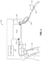
- FIG. 2 is a block diagram of a modular urine collection system 200.
- the urine collection system 200 includes a urine collection device 102, a first conduit 104, an additional conduit 128, a connect 126, a pump 210, a second conduit 118, a collection bag 120, and a power supply 124.
- the urine collection device 102, the first conduit 104, the pump 210, the second conduit 118, the collection bag 120, and the power supply 124 may include any of the urine collection devices 102, the first conduits 104, the additional conduits 128, the connectors, the second conduits 118, the collection bags 120, or the power supplies 124 described above in relation to the urine collection system 100.
- the urine collection system 200 may include the sleeve 140 and the pocket 142, as described above in relation to the urine collection system 100.
- one or more (e.g., all) of the container 108, the first three-way valve 112, or the second three-way valve 114 of the urine collection system 100 are absent from the urine collection system 200.
- the urine collection system 200 includes a modular architecture that allows one or more of the urine collection device 102, the additional conduit 128, the connector 126, the first conduit 104, the pump 210, the second conduit 118, the collection bag 120, the sleeve 140, or the pocket 142 to be replaced by a similar component or a component having features desired for specific activities.
- the modular architecture of the urine collection system 200 allows a patient to use the urine collection system 200 in a variety of settings, such as in bed, in a wheelchair, or ambulatory.
- the pump 210 in the urine collection system 200 may vary according to different embodiments.
- the pump 210 may include any of the features described above in relation to the pump 110.
- the pump 210 pulls air or fluid through the first conduit 104 and/or the first check valve 206, then exhausts the pulled air or fluid through the second check valve 216 and/or the second conduit 118.
- the pump 210 may include a piezoelectric pump.
- the pump 210 includes a disposable pump that includes the power supply 124 built into the disposable pump. When the power supply 124 in the disposable pump is depleted, a user may simply discard the disposable pump and replace the disposable pump with a new pump. The new pump replacing the disposable pump may also be a disposable pump, or may be a reusable pump.
- the first conduit 104 and the second conduit 118 are disconnected from the pump 210.
- the first conduit 104 is connected to an intake of the new pump, and the second conduit 118 is connected to an exhaust of the new pump.
- the pump 210 is selectively adjustable between multiple flow rates.
- a steady state of use by the pump 210 may include a first flow rate
- an intermittent state of use by the pump 210 may include a second flow rate that is greater than the first flow rate.
- the pump 210 may have a height of less than about 2.5 cm, a width of less than about 2.5 cm, and a depth of less than about 1.25 cm. The height, width, and depth of the pump 210 may vary according to different embodiments.
- the pump 210 may include a height of less than about 1.25 cm, less than about 2.5 cm, less than about 3.75 cm, less than about 5 cm, less than about 6.25 cm, less than about 7.5 cm, about 1.25 cm to about 7.5 cm, about 1.25 cm to about 2.5 cm, about 2.5 cm to about 3.75 cm, about 3.75 cm to about 5 cm, about 5 cm to about 6.25 cm, or about 6.25 cm to about 7 cm.
- the pump 210 may include a height of less than about 1.25 cm, less than about 2.5 cm, less than about 3.75 cm, less than about 5 cm, less than about 6.25 cm, less than about 7.5 cm, about 1.25 cm to about 7.5 cm, about 1.25 cm to about 2.5 cm, about 2.5 cm to about 3.75 cm, about 3.75 cm to about 5 cm, about 5 cm to about 6.25 cm, or about 6.25 cm to about 7 cm.
- the pump 210 may include a depth of less than about 0.5 cm, less than about 1 cm, less than about 1.5 cm, less than about 2 cm, less than about 2.5 cm, less than about 3 cm, less than about 3.5 cm, about 0.5 cm to about 3 cm, about 0.5 cm to about 1 cm, about 1 cm to about 1.5 cm, about 1.5 cm to about 2 cm, about 2 cm to about 2.5 cm, or about 2.5 cm to about 3 cm.
- Embodiments may include any of the heights, widths, and/or depths provided above.
- the pump 210 includes a width and a height of about 2 cm and a depth of about 3 mm.
- a wearer may attach the pump 210 to the collection bag 120, a bag such as a purse, a diaper, clothes (such as pants or belt), and so on.
- the pump 210 also may hang freely between the first conduit 104 and the second conduit 118 between the urine collection device 102 and the collection bag 120.
- the pump 210 also may include a first check valve 206 and a second check valve 216.
- the first check valve 206 is configured to provide fluid communication from the first conduit 104 into the pump 210 and prevent fluid communication from the pump 210 into the first conduit 104.
- the second check valve 216 is configured to provide fluid communication from the pump 210 to the second conduit 118 and prevent fluid communication from the second conduit 118 to the pump 210.
- the pump 210 may be connected directly to a port on the collection bag 120, and the second conduit 118 is absent from the urine collection system 200. In such an embodiment, the pump 210 connected directly to the port on the collection bag 120 pulls urine from the urine collection device 102 through the first conduit 104 and directly into the fluid collection bag 120.
- the collection bag 120 may include any of the collection bags 120 described in relation to the urine collection system 100.
- the collection bag 120 includes a urinalysis test strip configured to test one or more characteristics of urine collected in the collection bag 120.
- the urinalysis test strip may be detachably mounted to an exterior of the collection bag 120, thereby allowing a user to detach the urinalysis test strip from the bag to test the urine at a desired time.
- the urinalysis test strip may be mounted to an interior of the collection bag 120, and a user may view the urinalysis test strip through a transparent wall of the collection bag, thereby allowing a user to view one or more characteristics of the urine without opening the collection bag 120.
- the collection bag 120 includes a canister having one or more generally rigid walls.
- the urine collection system 200 also includes a power supply 124.
- the power supply 124 may be a modular power supply that is detachable from the urine collection system 200 and replaceable with a similar or different power supply. For example, a user may be plan to engage in a longer ambulatory activity, and therefore desire a longer lasting power supply. A user also may desire to switch an initial power supply to a new power supply when the initial power supply is depleted.
- the power supply 124 is built into the pump 210. That is, the pump 210 may include a housing or compartment for the power supply 210.
- the power supply 124 may be external to the pump 210, but may be electrically coupled to the pump 210 such that the power supply 124 may selectively power the pump 210.
- the power supply 124 may include one or more batteries, such as rechargeable batteries.
- the power supply 124 also may include a wire and plug configured to plug into a wall outlet.
- the power supply 124 may include one or more rechargeable batteries and a wire and plug configured to charge the one or more rechargeable batteries.
- the pump 210, the power supply 124, and the fluid collection bag 120 are sized and dimensioned to be simultaneously carried and/or worn by the user when the urine collection device 102 is positioned at least proximate to the urethra of the user.
- the pump 210 and the power supply 124 are sized and dimensioned to be detachably secured proximate to a waist of the user, and the urine collection bag 120 is sized and dimensioned to be positioned within the pocket 142 of the leg sleeve 140 worn on the leg of the user.
- FIG. 3 is a flow diagram of a method 300 for assembling a portable urine collection system.
- the method 300 includes an act 305 of connecting a first conduit to a fluid collection device to provide fluid communication between the urine collection device and the first conduit.
- the method 300 also includes an act 310 of connecting a second conduit to a urine collection bag to provide fluid communication between the second conduit and the urine collection bag.
- the method also includes an act 315 of connecting a modular pump to the first conduit and the second conduit.
- the modular pump is configured to pull a vacuum and draw urine from the urine collection device through the first conduit and force the urine through the second conduit into the urine collection bag.
- the method also includes an act 320 of replacing at least one of the first conduit, the second conduit, the urine collection device, the urine collection bag, or the modular pump.
- the act 320 of replacing at least one of the first conduit, the second conduit, the urine collection device, the urine collection bag, or the modular pump may be performed after one or more portions of the portable urine collection system have been activated or used.
- the act 320 of replacing at least one of the first conduit, the second conduit, the urine collection device, or the modular pump may be performed after the modular pump has been activated or operational for a period of time and/or at least some urine from the urine collection device has been collected in the urine collection bag,
- the act 320 includes disconnecting the urine collection device from the first conduit and connecting a different urine collection device to the first conduit or a different first conduit. In some embodiments, the act 320 includes disconnecting the second conduit from the urine collection bag and connecting a different urine collection bag to the second conduit or a different second conduit. In some embodiments, the act 320 includes disconnecting the first conduit from the modular pump and connecting a different first conduit to the modular pump or a different modular pump. In some embodiments, the act 320 includes disconnecting the second conduit from the modular pump and connecting a different second conduit to the modular pump or a different modular pump.
- the act 320 includes disconnecting the modular from the first conduit and the second conduit and connecting a different modular pump to the first conduit and the second conduit or at least one of a different first conduit or a different second conduit. In some embodiments, the act 320 includes at least disconnecting the urine collection bag from the second conduit and connecting the different urine collection bag to the second conduit or the different second conduit.
- the method 300 also may include one or more additional acts.
- the method 300 may include disconnecting a battery from the modular pump and connecting a different battery to the modular pump or a different modular pump.
- the method 300 also may include testing urine collected in the urine collection bag with one or more urinalysis strips attached to the urine collection bag.
- Acts 305, 310, 315, and 320 of the method 300 are for illustrative purposes.
- the acts 305, 310, 315, and 320 of the method 300 can be performed in different orders, split into multiple acts, modified, supplemented, or combined.
- one or more of the acts 305, 310, 315, and 320 of the method 300 can be omitted from the method 300.
- Any of the acts 305, 310, 315, and 320 can include using any of the portable urine collection systems disclosed herein.
- the term “about” or “substantially” refers to an allowable variance of the term modified by “about” or “substantially” by ⁇ 10% or ⁇ 5%. Further, the terms “less than,” “or less,” “greater than,” “more than,” or “or more” include, as an endpoint, the value that is modified by the terms “less than,” “or less,” “greater than,” “more than,” or “or more.”
Landscapes
- Health & Medical Sciences (AREA)
- Life Sciences & Earth Sciences (AREA)
- General Health & Medical Sciences (AREA)
- Engineering & Computer Science (AREA)
- Biomedical Technology (AREA)
- Heart & Thoracic Surgery (AREA)
- Animal Behavior & Ethology (AREA)
- Public Health (AREA)
- Veterinary Medicine (AREA)
- Orthopedic Medicine & Surgery (AREA)
- Vascular Medicine (AREA)
- Nursing (AREA)
- Epidemiology (AREA)
- Physiology (AREA)
- Urology & Nephrology (AREA)
- Physics & Mathematics (AREA)
- Biophysics (AREA)
- Pathology (AREA)
- Medical Informatics (AREA)
- Molecular Biology (AREA)
- Surgery (AREA)
- Orthopedics, Nursing, And Contraception (AREA)
- External Artificial Organs (AREA)
Description
- An individual may have limited or impaired mobility such that typical urination processes are challenging or impossible. For example, the individual may have had surgery or may have a disability that impairs mobility. In another example, the individual may have restricted travel conditions such as those experienced by pilots, drivers, and workers in hazardous areas. Additionally, fluid collection from the individual may be needed for monitoring purposes or clinical testing.
- Bed pans and urinary catheters, such as a Foley catheter, may be used to address some of these circumstances. However, bed pans and urinary catheters have several problems associated therewith. For example, bed pans may be prone to discomfort, spills, and other hygiene issues. Urinary catheters be may be uncomfortable, painful, and may cause urinary tract infections.
- Thus, users and manufacturers of fluid collection devices continue to seek new and improved devices, systems, and methods to collect urine.
- The invention is defined in the independent claims below. The dependent claims are directed to optional features and preferred embodiments. The two-part form of claim 1 is inspired by
EP-A1-610638 - A method of assembling a portable urine collection system is disclosed. The method includes connecting a first conduit to a urine collection device to provide fluid communication between the urine collection device and the first conduit. The method also includes connecting a second conduit to a urine collection bag to provide fluid communication between the second conduit and the urine collection bag. The method also includes connecting a modular pump to the first conduit and the second conduit, the modular pump configured to pull a vacuum and draw urine from the urine collection device through the first conduit and force the urine through the second conduit into the urine collection bag. The method also includes, after collecting at least some urine from the urine collection device in the urine collection bag, replacing at least one of the first conduit, the second conduit, the urine collection device, the urine collection bag, and/or the modular pump with a different first conduit, a different second conduit, a different urine collection bag, a different urine collection device, and/or a different modular pump.
- Also disclosed below is a portable urine collection system which includes a container including an interior region, a modular pump in fluid communication with the interior region, and a backpack. The modular pump is configured to pull a vacuum and draw urine from a urine collection device positioned proximate to a urethra of a user into the interior region of the chamber. The backpack is configured to be worn by the user and sized and dimensioned to hold the container and the modular pump therein when being worn by the user.
- Features from any of the disclosed embodiments may be used in combination with one another, without limitation. In addition, other features and advantages of the present disclosure will become apparent to those of ordinary skill in the art through consideration of the following detailed description and the accompanying drawings.
- The drawings illustrate the present disclosure, wherein identical reference numerals refer to identical or similar elements or features in different views or embodiments shown in the drawings.
-
FIG. 1 is a block diagram of a portable urine collection system. -
FIG. 2 is a block diagram of a portable urine collection system. -
FIG. 3 is a flow diagram of a method for assembling a portable urine collection system. - Disclosed below are fluid collection devices and methods of using the same. The devices and systems disclosed herein are configured to collect fluids from an individual. The fluids collected by the fluid collection devices may include at least one of urine, vaginal discharge, penile discharge, reproductive fluids, blood, sweat, or other bodily fluids.
- Conventional urine collection systems are typically designed for patients confined to a bed and, accordingly, typically have a fixed architecture including a urine collection device, a conduit, a urine collection container, and a pump. For example, in a conventional urine collection system, if a pump of the urine collection system is no longer functional, additional elements of the urine collection system may also need to be replaced in addition to the pump. Moreover, conventional urine collection systems may also be limited to and/or compatible with a single type or size of pump, and a user or caregiver is prohibited from interchanging the pump with a different pump to meet the needs of the user or certain circumstances. These aspects of conventional urine collection systems can be detrimental to the environment and increase unnecessary waste.
- Embodiments of the invention presented herein include a modular architecture that allows one or more components to be replaced by a similar component or a component having features desired for specific activities or a specific user. The one or more components may be configured for replacement by an end user after an original component has been used, malfunctions, or does not operate with the end user as desired. For example, a female urine collection device may be removed and replaced with a male urine collection device, a smaller urine collection device can be replaced with a larger urine collection device, a smaller power source can be replaced with a larger power source, one pump can be replaced with another pump, a dysfunctional pump or power source can be replaced with a functioning pump or power source, a soiled or kinked conduit can be replaced with a clean conduit, a soiled urine collection device can be replaced with a clean urine collection device, and so on. Embodiments of modular urine collection systems described herein also allow a user to reuse one or more of the pump, the power source (e.g., battery), the controller, or the three-way valves, while one or more of the urine collection device, the conduit, or the collection bag may be disposable. A disposable device, such as a disposable modular pump, includes a device that may be manually disconnected from the system by a user or caregiver without damaging the remaining system, and then placed in the garbage or rubbish bin. The one or more components may be replaced with different components by the user at the convenience or preference of the user. Connectors between modular components are universal, allowing each component to be replaced with a suitable counterpart.
- Conventional urine collection systems may be sized and dimensioned for a user to use the conventional urine collection system in bed next to a wall-mounted power source but nowhere else. However, incontinent ambulatory users have need for a urine collection system that allows them to carry about more normal activities without the embarrassment of soiling his/her clothes.
- The modular architecture of the urine collection systems described herein also may be portable by the user or caregiver without assistance of a motorized vehicle. A portable urine collection system is sized, dimensioned, and weighted to allow a user or caregiver to carry the entire urine collection system with, for example, only the assistance of a backpack and/or a sleeve. Thus, the portable and modular architecture of urine collection systems described herein also allows the patient or end user to use the system in a variety of settings, such as a wheelchair or ambulatory. For ambulatory users, in many of the urine collection systems described herein, the pump, the battery, and the fluid collection bag are sized and dimensioned to be simultaneously carried by the user when the urine collection device is positioned at least proximate to the urethra of the user. Also for ambulatory users, in many of the urine collection systems describe herein the pump and the power supply are sized and dimensioned to be detachably secured proximate to a waist of the user and the urine collection bag is sized and dimensioned to be positioned within a pocket of a leg sleeve worn on the leg of the user.
-
FIG. 1 is a block diagram of a portableurine collection system 100. Theurine collection system 100 includes aurine collection device 102, afirst conduit 104, acontainer 108, apump 110, asecond conduit 118, acollection bag 120, acontroller 122, and apower supply 124. While theurine collection device 102 shown inFIG. 1 includes a female urine collection device, theurine collection device 102 may instead include a male urine collection device. PCT International Application No.PCT/US2019/029616 , for example, describes various embodiments of both male and female fluid collection devices. Moreover, theurine collection device 102 may be interchangeable in theurine collection system 100 between different types, varieties, and sizes of male or female urine collection devices. Theurine collection device 102 is configured to be positioned proximate or adjacent to a urethra of a user. Generally, theurine collection device 102 may include a surface sized to be positioned proximate or adjacent to the urethra and configured to wick urine or other fluids away from the user. Urine or other fluids may be wicked from the surface to a reservoir in theurine collection device 102. - The
urine collection system 100 also includes afirst conduit 104. Thefirst conduit 104 is configured to provide fluid communication between thepump 110 and theurine collection device 102, and may include a flexible tube. In many embodiments, thefluid collection device 102 includes aconnector 126 configured to connect to thefirst conduit 104. Thefluid collection device 102 also may include anadditional conduit 128 connecting theconnector 126 and the body of thefluid collection device 102. Theadditional conduit 128 may provide fluid communication with the reservoir of theurine collection device 102 or an interior portion of theurine collection device 102 to allow urine to be withdrawn from theurine collection device 102 through theadditional conduit 128. When connected, theadditional conduit 128 provides fluid communication between thefirst conduit 104 and theurine collection device 102. In some embodiments, thefirst conduit 104 may connect directly to theurine collection device 102 to provide fluid communication with the reservoir of theurine collection device 102 or an interior portion of theurine collection device 102 to allow urine to be withdrawn from the urine collection device through thefirst conduit 104. - The
urine collection system 100 also includes acontainer 108 that may be generally rigid. For example, thecontainer 108 may be more rigid than the collection bag. A generallyrigid container 108 of this disclosure is configured to hold its shape under the vacuum and positive pressures exerted by thepump 110. In some embodiments, thecontainer 108 is sized to hold a smaller volume of fluid or air than thecollection bag 120. For example, thecontainer 108 may be sized to hold less than 500 mL of fluid or air, while thecollection bag 120 may be sized to hold at least 1000 mL of fluid or air. In some embodiments, thecontainer 108 may be sized to hold about 200 mL to about 400 mL of fluid or air and thecollection bag 120 may be sized to hold at least about 1000 mL or at least about 1500 mL of fluid or air. - The
first conduit 104 is connected to thecontainer 108. Theurine collection system 100 also may include afirst check valve 106 providing fluid communication from thefirst conduit 104 into thecontainer 108, while preventing fluid communication from thecontainer 108 into thefirst conduit 104. For example, upon activation of thepump 110, a vacuum formed in thecontainer 108 may pull a vacuum on thefirst conduit 104, thereby pulling fluid from at least one of thefirst conduit 104 or theurine collection device 102 and into thecontainer 108. Thefirst check valve 106, however, also may prevent fluid collected in thecontainer 108 from passing through thefirst check valve 106 into thefirst conduit 104. - In some embodiments, the
container 108 also is connected to thesecond conduit 118. Theurine collection system 100 may include asecond check valve 116 providing fluid communication from thecontainer 108 into thesecond conduit 118, while preventing fluid communication from thesecond conduit 118 into thecontainer 108. For example, when thepump 110 is activated and a vacuum is formed in thecontainer 108, thesecond check valve 116 may prevent fluid communication from thesecond conduit 118 into thecontainer 108, thereby preventing any fluids in thesecond conduit 118 or thecollection bag 120 from passing through thesecond check valve 116 and entering thecontainer 108. When a predetermined positive pressure is formed in thecontainer 108 upon activation of the pump, thesecond check valve 116 may provide fluid communication from thecontainer 108 into thesecond conduit 118, thereby forcing fluid in thecontainer 108 through thesecond check valve 116 into thesecond conduit 118 and into thecollection bag 120. - The
second conduit 118 may be connected to thecontainer 108 and configured to provide fluid communication between thecontainer 108 and thecollection bag 120 when the predetermined positive pressure is formed in thecontainer 108 to force fluid in thecontainer 108 through thesecond check valve 116 into thesecond conduit 118. Thesecond conduit 118 may include a flexible tube. Thesecond conduit 118 may be connected directly to thecollection bag 120. In some embodiments, thesecond conduit 118 is connected to a connector that is connected to thecollection bag 120. An additional conduit may connect the connector to thecollection bag 120. The additional conduit may provide fluid communication with an interior portion of thecollection bag 120 to allow urine to be forced through thesecond conduit 118 into thecollection bag 120. When connected, the additional conduit provides fluid communication between thesecond conduit 118 and thecollection bag 120. - The
collection bag 120 may be a collapsible or expandable bag sized to hold more fluid or air than thecontainer 108. For example, thecollection bag 120 may be generally flat when empty, but may expand when urine or other fluid is forced into the collection back 120. Thecollection bag 120 also may include one or more vents. The one or more vents may be configured to allow air in thecollection bag 120 to exit thecollection bag 120, but prevent fluid in thecollection bag 120 from exiting thecollection bag 120 through the one or more vents. Thecollection bag 120 also may include a discharge port for emptying fluid from thecollection bag 120. - The
pump 110 of theurine collection system 110 may include any of a variety of pumps, such as a diaphragm pump. Thepump 110 may include multiple flow rates that allow a user or wearer to select a desired or preferred flow rate. For example, a higher flow rate may be required to force fluid out of thecontainer 108 than is required to pull fluid into thecontainer 108. As noted above, thepump 110 may include a removable or modular pump that allows a user to remove thepump 110 and attach a different pump to theurine collection system 110. Thepump 110 also may include a portable pump that is transportable by a user or wearer. For example, thepump 110 may be sized to carry in abackpack 150 or attached to the clothing of a user or wearer. - The
pump 110 also is configured to pull a vacuum in thefirst conduit 104 to pull fluid from theurine collection device 102. Thepump 110 also may be configured force fluid through thesecond conduit 118 into thecollection bag 120. In some embodiments, thepump 110 is a reversible pump, configured to selectively pull fluid or air in and push fluid or air out. For example, thepump 110 may be fluidly coupled to thecontainer 108 and may be reversible between a first pump action and a second pump action. During the first pump action, thepump 110 pulls a vacuum in thecontainer 108 to pull urine or other fluids through thefirst check valve 106 into thecontainer 108. During the second pump action, thepump 110 creates a positive pressure in thecontainer 108, thereby forcing urine through thesecond check valve 116 into thesecond conduit 118 and thecollection bag 120. - In many embodiments, the
pump 110 may include anair intake 111 and anair exhaust 113. Upon activation of thepump 110, theair intake 111 may draw air into thepump 110 through theair intake 111 and theair exhaust 113 may force air out of thepump 110 through theair exhaust 113. Theurine collection system 100 also may include a first three-way valve 112 and a second three-way valve 114. The first three-way valve 112 may be connected to theair intake 111 and a first port on thecontainer 108, while the second three-way valve 112 may be connected to theair exhaust 113 and a second port on thecontainer 108. - The first three-
way valve 112 and the second three-way valve 114 are each operable in a first configuration and a second configuration and may, in selected configurations, provide fluid communication between thepump 110 and the container. The first three-way valve 112 includes a first configuration that provides fluid communication between thecontainer 108 and thepump 110. The configuration of the first three-way valve 112 also may be selectively changed or switched to a second configuration that prevents fluid communication between thecontainer 108 and thepump 110, but provides fluid communication between thepump 110 andambient air 115 from outside or around the first three-way valve 112. The second three-way valve 114 includes a first configuration that provides fluid communication between thecontainer 108 and thepump 110. The configuration of the second three-way valve 114 also may be selectively changed or switched to a second configuration that prevents fluid communication between thecontainer 108 and thepump 110, but provides fluid communication between thepump 110 and theambient air 115. - Upon activation of the
pump 110, the first three-way valve 112 and the second three-way valve 144 allow thepump 110 to either pull a vacuum on thefirst conduit 104 to pull fluid from theurine collection device 102 into thecontainer 108 or force fluid in thecontainer 108 through thesecond conduit 118 into thecollection bag 120. Theurine collection system 100, then, can alternate between a collection mode C and a transfer mode T. In the collection mode C, the first three-way valve 112 is in the first configuration (that provides fluid communication between thecontainer 108 and the pump 110) and the second three-way valve 114 is in the second configuration (that prevents fluid communication between thecontainer 108 and thepump 110, but provides fluid communication between thepump 110 and the ambient air 115). Activation of thepump 110 when theurine collection system 100 is in the collection mode C pulls air through the first three-way valve 112 and theair intake 111 into thepump 110 from thecontainer 108 and exhausts the air through theair exhaust 113 and the second three-way valve 114 to theambient air 115 outside or around the second three-way valve 114. This flow of air pulls a vacuum on theurine collection device 102 and thefirst conduit 104 sufficient to pull fluid from theurine collection device 102 and thefirst conduit 104 through thefirst check valve 106 into thecontainer 108. - In the transfer mode T, the first three-
way valve 112 is in the second configuration (that prevents fluid communication between thecontainer 108 and thepump 110, but provides fluid communication between thepump 110 andambient air 115 from outside or around the first three-way valve 112) and the second three-way valve 114 is in the first configuration (that provides fluid communication between thecontainer 108 and the pump 110). Activation of thepump 110 when the urine collection system is in the transfer mode T pulls theambient air 115 through the first three-way valve 112 and theair intake 111, then forces the air through theair exhaust 113 and the second three-way valve 114 into thecontainer 108. This flow of air creates a positive pressure in thecontainer 108 sufficient to force the fluid in thecontainer 108 through thesecond check valve 116 and thesecond conduit 118 and into theurine collection bag 120. - The
urine collection system 100 also includes apower supply 124. Thepower supply 124 may be a modular power supply that is detachable from theurine collection system 100 and replaceable with a similar or different power supply. For example, a user may be plan to engage in a longer ambulatory activity, and therefore desire a longer lasting power supply. A user also may desire to switch an initial power supply to a new power supply when the initial power supply is depleted. In some embodiments, thepower supply 124 is built into thepump 110. That is, thepump 110 may include a housing or compartment for thepower supply 124. In some embodiments, thepower supply 124 may be external to thepump 110, but may be electrically coupled to thepump 110 such that thepower supply 124 may selectively power thepump 110. Thepower supply 124 may include one or more batteries, such as rechargeable batteries. Thepower supply 124 also may include a wire and plug configured to plug into a wall outlet. In some embodiments, thepower supply 124 may include one or more rechargeable batteries and a wire and plug configured to charge the one or more rechargeable batteries. - The
urine collection system 100 also may include acontroller 122. Thecontroller 122 may be electrically coupled to thepump 110 and thepower supply 124. Thecontroller 122 is configured to activate or deactivate thepump 110. Thecontroller 122 also may be configured to alternate theurine collection system 100 between the collection mode C and the transfer mode T, including changing the first three-way valve 112 and the second three-way valve 122 between the respective first and second configurations. For example, thecontroller 122 may alternate theurine collection system 100 between the collection mode C and the transfer mode T at predetermined or preselected time intervals. In some embodiments, theurine collection system 100 includes a sensor (125) configured to detect a property related at least to a volume of the urine in thecontainer 108, and thecontroller 122 may alternate theurine collection system 100 between the collection mode C and the transfer mode T responsive to a property related at least to the volume of the urine in thecontainer 108 sensed by the sensor. For example, thesensor 125 may detect that the container is full or nearing urine capacity, and thecontroller 122 may alternate the urine collection system from the collection mode C to the transfer mode T. In some embodiments, thecontroller 122 includes one or more manual switches that allow an operator, such as the user or wearer, to activate or deactivate thepump 110 and/or change the first three-way valve 112 and the second three-way valve 122 between the respective first and second configurations. - In some embodiments, the
controller 122 may include at least one computing device that may be configured to perform one or more of the acts described herein. The at least one computing device may include one or more servers, or one or more portable computing devices (e.g., smartphone, tablet, etc.). The computing device may comprise at least one processor, memory, a storage device, an input/output ("I/O") device/interface, and a communication interface. The computer device of thecontroller 122, then, may be configured to activate or deactivate thepump 110 and/or alternate theurine collection system 100 between the collection mode C and the transfer mode T. In some embodiments, thecontroller 122 may activate or deactivate thepump 110 and/or alternate theurine collection system 100 between the collection mode C and the transfer mode T in response to commands from the operator. In some embodiments, thecontroller 122 may automatically activate or deactivate thepump 110 and/or alternate theurine collection system 100 between the collection mode C and the transfer mode T. For example, thecontroller 122 may automatically activate or deactivate thepump 110 and/or alternate theurine collection system 100 between the collection mode C and the transfer mode T at predetermined or selected time intervals. Thecontroller 122 also may activate or deactivate thepump 110 and/or alternate theurine collection system 100 between the collection mode C and the transfer mode T responsive to conditions sensed by one or more sensors in at least one of theurine collection device 102, thefirst conduit 104, thesmall reservoir 108, thesecond conduit 118, or thecollection bag 120. - Because the
urine collection system 100 may be portable for use by an ambulatory user, in embodiments, thepump 110, thepower supply 124, and thefluid collection bag 120 are sized and dimensioned to be simultaneously carried and/or worn by the user when theurine collection device 102 is positioned at least proximate to the urethra of the user. In some embodiments, thepump 110 and thepower supply 124 are sized and dimensioned to be detachably secured proximate to a waist of the user, and theurine collection bag 120 is sized and dimensioned to be positioned within thepocket 142 of theleg sleeve 140 worn on the leg of the user. - The
collection bag 120 may be configured to be carried in a bag holder. For example, theurine collection system 100 may include aleg sleeve 140 having apocket 142 sized to hold thecollection bag 120. Thepocket 142 may include may be configured to allow thecollection bag 120 to expand in volume as thecollection bag 120 fills with fluid. For example thepocket 142 may include an elastic material. Thecollection bag 120 also may be configured to be carried in abackpack 150 or waist pack. In some embodiments, one or more of thepump 110, the first three-way valve 112, the second three-way valve 114, thecontroller 122, or thepower supply 124 also may be held or carried in thebackpack 150. In some embodiments, each of thecollection bag 120, thesecond conduit 118, thesecond check valve 116, thepump 110, the first three-way valve 112, the second three-way valve 114, thecontroller 122, or thepower supply 124 are held or carried in thebackpack 150. In some embodiments, each of thecontainer 108, thepump 110, thecontroller 122, thepower supply 124, the first three-way valve 112, and the second three-way valve 114 may be positioned in thebackpack 150 or a waist pack, while thecollection bag 120 is secured in thepocket 142 of theleg sleeve 140. Carrying thecollection bag 120, thecontainer 108, thepump 110, thecontroller 122, thepower supply 124, the first three-way valve 112, and the second three-way valve 114, in one or more of theleg sleeve 140, thebackpack 150, or a waist pack provides a wearer with a discreet way of collecting urine and sense of normalcy as he/she performs routine activities. -
FIG. 2 is a block diagram of a modularurine collection system 200. Theurine collection system 200 includes aurine collection device 102, afirst conduit 104, anadditional conduit 128, aconnect 126, apump 210, asecond conduit 118, acollection bag 120, and apower supply 124. Unless otherwise noted, theurine collection device 102, thefirst conduit 104, thepump 210, thesecond conduit 118, thecollection bag 120, and thepower supply 124 may include any of theurine collection devices 102, thefirst conduits 104, theadditional conduits 128, the connectors, thesecond conduits 118, thecollection bags 120, or the power supplies 124 described above in relation to theurine collection system 100. Moreover, in many embodiments, theurine collection system 200 may include thesleeve 140 and thepocket 142, as described above in relation to theurine collection system 100. In some embodiments of theurine collection system 200, one or more (e.g., all) of thecontainer 108, the first three-way valve 112, or the second three-way valve 114 of theurine collection system 100 are absent from theurine collection system 200. - The
urine collection system 200 includes a modular architecture that allows one or more of theurine collection device 102, theadditional conduit 128, theconnector 126, thefirst conduit 104, thepump 210, thesecond conduit 118, thecollection bag 120, thesleeve 140, or thepocket 142 to be replaced by a similar component or a component having features desired for specific activities. The modular architecture of theurine collection system 200 allows a patient to use theurine collection system 200 in a variety of settings, such as in bed, in a wheelchair, or ambulatory. - The
pump 210 in theurine collection system 200 may vary according to different embodiments. Thepump 210 may include any of the features described above in relation to thepump 110. In operation, thepump 210 pulls air or fluid through thefirst conduit 104 and/or thefirst check valve 206, then exhausts the pulled air or fluid through thesecond check valve 216 and/or thesecond conduit 118. Thepump 210 may include a piezoelectric pump. In some embodiments, thepump 210 includes a disposable pump that includes thepower supply 124 built into the disposable pump. When thepower supply 124 in the disposable pump is depleted, a user may simply discard the disposable pump and replace the disposable pump with a new pump. The new pump replacing the disposable pump may also be a disposable pump, or may be a reusable pump. To replace thepump 210, thefirst conduit 104 and thesecond conduit 118 are disconnected from thepump 210. To replace the discardedpump 210, thefirst conduit 104 is connected to an intake of the new pump, and thesecond conduit 118 is connected to an exhaust of the new pump. - In some embodiments, the
pump 210 is selectively adjustable between multiple flow rates. For example, a steady state of use by thepump 210 may include a first flow rate, while an intermittent state of use by thepump 210 may include a second flow rate that is greater than the first flow rate. Thepump 210 may have a height of less than about 2.5 cm, a width of less than about 2.5 cm, and a depth of less than about 1.25 cm. The height, width, and depth of thepump 210 may vary according to different embodiments. In some embodiments, thepump 210 may include a height of less than about 1.25 cm, less than about 2.5 cm, less than about 3.75 cm, less than about 5 cm, less than about 6.25 cm, less than about 7.5 cm, about 1.25 cm to about 7.5 cm, about 1.25 cm to about 2.5 cm, about 2.5 cm to about 3.75 cm, about 3.75 cm to about 5 cm, about 5 cm to about 6.25 cm, or about 6.25 cm to about 7 cm. In some embodiments, thepump 210 may include a height of less than about 1.25 cm, less than about 2.5 cm, less than about 3.75 cm, less than about 5 cm, less than about 6.25 cm, less than about 7.5 cm, about 1.25 cm to about 7.5 cm, about 1.25 cm to about 2.5 cm, about 2.5 cm to about 3.75 cm, about 3.75 cm to about 5 cm, about 5 cm to about 6.25 cm, or about 6.25 cm to about 7 cm. In some embodiments, thepump 210 may include a depth of less than about 0.5 cm, less than about 1 cm, less than about 1.5 cm, less than about 2 cm, less than about 2.5 cm, less than about 3 cm, less than about 3.5 cm, about 0.5 cm to about 3 cm, about 0.5 cm to about 1 cm, about 1 cm to about 1.5 cm, about 1.5 cm to about 2 cm, about 2 cm to about 2.5 cm, or about 2.5 cm to about 3 cm. Embodiments may include any of the heights, widths, and/or depths provided above. In an example, thepump 210 includes a width and a height of about 2 cm and a depth of about 3 mm. - A wearer may attach the
pump 210 to thecollection bag 120, a bag such as a purse, a diaper, clothes (such as pants or belt), and so on. Thepump 210 also may hang freely between thefirst conduit 104 and thesecond conduit 118 between theurine collection device 102 and thecollection bag 120. Thepump 210 also may include afirst check valve 206 and asecond check valve 216. Thefirst check valve 206 is configured to provide fluid communication from thefirst conduit 104 into thepump 210 and prevent fluid communication from thepump 210 into thefirst conduit 104. Thesecond check valve 216 is configured to provide fluid communication from thepump 210 to thesecond conduit 118 and prevent fluid communication from thesecond conduit 118 to thepump 210. In some embodiments, thepump 210 may be connected directly to a port on thecollection bag 120, and thesecond conduit 118 is absent from theurine collection system 200. In such an embodiment, thepump 210 connected directly to the port on thecollection bag 120 pulls urine from theurine collection device 102 through thefirst conduit 104 and directly into thefluid collection bag 120. - The
collection bag 120 may include any of thecollection bags 120 described in relation to theurine collection system 100. In some embodiments, thecollection bag 120 includes a urinalysis test strip configured to test one or more characteristics of urine collected in thecollection bag 120. The urinalysis test strip may be detachably mounted to an exterior of thecollection bag 120, thereby allowing a user to detach the urinalysis test strip from the bag to test the urine at a desired time. The urinalysis test strip may be mounted to an interior of thecollection bag 120, and a user may view the urinalysis test strip through a transparent wall of the collection bag, thereby allowing a user to view one or more characteristics of the urine without opening thecollection bag 120. In some embodiments, thecollection bag 120 includes a canister having one or more generally rigid walls. - The
urine collection system 200 also includes apower supply 124. Thepower supply 124 may be a modular power supply that is detachable from theurine collection system 200 and replaceable with a similar or different power supply. For example, a user may be plan to engage in a longer ambulatory activity, and therefore desire a longer lasting power supply. A user also may desire to switch an initial power supply to a new power supply when the initial power supply is depleted. In some embodiments, thepower supply 124 is built into thepump 210. That is, thepump 210 may include a housing or compartment for thepower supply 210. In some embodiments, thepower supply 124 may be external to thepump 210, but may be electrically coupled to thepump 210 such that thepower supply 124 may selectively power thepump 210. Thepower supply 124 may include one or more batteries, such as rechargeable batteries. Thepower supply 124 also may include a wire and plug configured to plug into a wall outlet. In some embodiments, thepower supply 124 may include one or more rechargeable batteries and a wire and plug configured to charge the one or more rechargeable batteries. - Because the
urine collection system 200 may be portable for use by an ambulatory user, in embodiments, thepump 210, thepower supply 124, and thefluid collection bag 120 are sized and dimensioned to be simultaneously carried and/or worn by the user when theurine collection device 102 is positioned at least proximate to the urethra of the user. In some embodiments, thepump 210 and thepower supply 124 are sized and dimensioned to be detachably secured proximate to a waist of the user, and theurine collection bag 120 is sized and dimensioned to be positioned within thepocket 142 of theleg sleeve 140 worn on the leg of the user. -
FIG. 3 is a flow diagram of amethod 300 for assembling a portable urine collection system. Themethod 300 includes anact 305 of connecting a first conduit to a fluid collection device to provide fluid communication between the urine collection device and the first conduit. Themethod 300 also includes anact 310 of connecting a second conduit to a urine collection bag to provide fluid communication between the second conduit and the urine collection bag. The method also includes anact 315 of connecting a modular pump to the first conduit and the second conduit. The modular pump is configured to pull a vacuum and draw urine from the urine collection device through the first conduit and force the urine through the second conduit into the urine collection bag. The method also includes anact 320 of replacing at least one of the first conduit, the second conduit, the urine collection device, the urine collection bag, or the modular pump. - The
act 320 of replacing at least one of the first conduit, the second conduit, the urine collection device, the urine collection bag, or the modular pump may be performed after one or more portions of the portable urine collection system have been activated or used. For example, theact 320 of replacing at least one of the first conduit, the second conduit, the urine collection device, or the modular pump may be performed after the modular pump has been activated or operational for a period of time and/or at least some urine from the urine collection device has been collected in the urine collection bag, - In some embodiments, the
act 320 includes disconnecting the urine collection device from the first conduit and connecting a different urine collection device to the first conduit or a different first conduit. In some embodiments, theact 320 includes disconnecting the second conduit from the urine collection bag and connecting a different urine collection bag to the second conduit or a different second conduit. In some embodiments, theact 320 includes disconnecting the first conduit from the modular pump and connecting a different first conduit to the modular pump or a different modular pump. In some embodiments, theact 320 includes disconnecting the second conduit from the modular pump and connecting a different second conduit to the modular pump or a different modular pump. In some embodiments, theact 320 includes disconnecting the modular from the first conduit and the second conduit and connecting a different modular pump to the first conduit and the second conduit or at least one of a different first conduit or a different second conduit. In some embodiments, theact 320 includes at least disconnecting the urine collection bag from the second conduit and connecting the different urine collection bag to the second conduit or the different second conduit. - The
method 300 also may include one or more additional acts. For example, themethod 300 may include disconnecting a battery from the modular pump and connecting a different battery to the modular pump or a different modular pump. Themethod 300 also may include testing urine collected in the urine collection bag with one or more urinalysis strips attached to the urine collection bag. -
Acts method 300 are for illustrative purposes. For example, theacts method 300 can be performed in different orders, split into multiple acts, modified, supplemented, or combined. In an embodiment, one or more of theacts method 300 can be omitted from themethod 300. Any of theacts - As used herein, the term "about" or "substantially" refers to an allowable variance of the term modified by "about" or "substantially" by ±10% or ±5%. Further, the terms "less than," "or less," "greater than," "more than," or "or more" include, as an endpoint, the value that is modified by the terms "less than," "or less," "greater than," "more than," or "or more."
- While various aspects and embodiments have been disclosed herein, other aspects and embodiments are contemplated. The various aspects and embodiments disclosed herein are for purposes of illustration and are not intended to be limiting.
Claims (15)
- A portable urine collection system (100), comprising:a urine collection device (102) configured to be positioned at least proximate to a urethra of a user;a first conduit (104) in fluid communication with the urine collection device;a urine collection bag (120) having an interior region;a second conduit (118) in fluid communication with the interior region of the urine collection bag;a pump (110) configured to pull a vacuum and draw urine from the urine collection device through the first conduit and force the urine through the second conduit into the interior region of the urine collection bagthe system being characterized in that:
its pump and urine collector bag components are modular, with connectors between the modular components that are universal, thereby allowing the end user of the system to select different combinations of the modular components for different settings, in particular, when in bed, when in a wheelchair or when walking. - The portable urine collection system of claim 1, wherein the modular pump (210) includes a disposable modular pump with an inbuilt power supply (124) removably connected to the first conduit and the second conduit.
- The portable urine collection system of of claim 1 or 2, further comprising a battery (124) removably connected to the modular pump.
- The portable urine collection system of claim 3, wherein the pump, the battery, and the fluid collection bag are sized and dimensioned to be simultaneously carried by the user when the urine collection device is positioned at least proximate to the urethra of the user.
- The portable urine collection system of claim 4, wherein the pump and the power supply are sized and dimensioned to be detachably secured proximate to a waist of the user and the urine collection bag is sized and dimensioned to be positioned within a pocket of a leg sleeve worn on the leg of the user.
- The portable urine collection system of claim 1, further comprising:a container connected to the first conduit and the second conduit, the container being more rigid and having a smaller volume than the urine collection bag;a first check valve (106) providing fluid communication from the first conduit into the container and preventing fluid communication from the container into the first conduit;a second check valve (116) providing fluid communication from the container to the second conduit and preventing fluid communication from the second conduit to the container;a first three-way valve (112) having:a first configuration providing fluid communication between the container and the modular pump; anda second configuration preventing fluid communication between the container and the modular pump, and providing fluid communication between the modular pump and ambient air; anda second three-way valve (144) having:a first configuration providing fluid communication between the container and the modular pump; anda second configuration preventing fluid communication between the container and the modular pump, and providing fluid communication between the modular pump and the ambient air;wherein:when the first three-way valve is in the first configuration and the second three-way valve is in the second configuration, activation of the modular pump pulls air through the first three-way valve into the modular pump from the container and exhausts air through the second three-way valve, thereby pulling a vacuum on the urine collection device and the first conduit to pull the urine from the urine collection device and the first conduit through the first check valve into the container; andwhen the first three-way valve is in the second configuration and the second three-way valve is in the first configuration, activation of the modular pump pulls the ambient air through the first three-way valve and forces the ambient air through the second three-way valve into the container, thereby forcing the urine in the container through the second check valve and the second conduit and into the urine collection bag.
- The portable urine collection system of claim 6, further comprising a controller (122) operably coupled to the first three-way valve and the second three-way valve, the controller configured to:adjust the first three-way valve between the first configuration and the second configuration;adjust the second three-way valve between the first configuration and the second configuration; andactivate and deactivate the pump.
- The portable urine collection system of claim 7, further comprising a battery (124) removably connected to the modular pump and the controller.
- The portable urine collection system of claim 8, wherein the battery, the modular pump, the controller, the container the first three-way valve, the second three-way valve, the first check valve, and the second check valve are sized and dimensioned to simultaneously fit within a backpack (150) worn by the user.
- The portable urine collection system of claim 9, further comprising the backpack sized and dimensioned to hold the battery, the pump, the controller, the container the first three-way valve, the second three-way valve, the first check valve, and the second check valve therein.
- The system of any one of claims 6 to 10 that can alternate between a collection mode (C) and a transfer mode (T).
- The system of claim 11 as dependent on claim 7, wherein the controller may automatically activate or deactivate the pump (110) and/or alternate the urine collection system (100) between the collection mode (C) and the transfer mode (T).
- A method of assembling a portable urine collection system which enables an end user of the system to select different combinations of modular components of the system for different settings, in particular, when in bed, when in a wheelchair or when walking, the method comprising:connecting a first conduit to a urine collection device to provide fluid communication between the urine collection device and the first conduit;connecting a second conduit to a urine collection bag to provide fluid communication between the second conduit and the urine collection bag;connecting a modular pump to the first conduit and the second conduit, the modular pump configured to pull a vacuum and draw urine from the urine collection device through the first conduit and force the urine through the second conduit into the urine collection bag; andafter collecting at least some urine from the urine collection device in the urine collection bag, replacing at least one of the first conduit, the second conduit, the urine collection device, the urine collection bag, and/or the modular pump with a different first conduit, a different second conduit, a different urine collection device, a different urine collection bag, and/or a different modular pump.
- The method of claim 13, further comprising inserting the modular pump and/or the different modular pump into a backpack configured to be worn by the user.
- The method of claim 13, further comprising securing the modular pump proximate to the waist of the user.
Priority Applications (1)
| Application Number | Priority Date | Filing Date | Title |
|---|---|---|---|
| EP24166233.7A EP4378431A3 (en) | 2019-11-21 | 2020-11-20 | Portable urine collection system and related methods |
Applications Claiming Priority (2)
| Application Number | Priority Date | Filing Date | Title |
|---|---|---|---|
| US201962938447P | 2019-11-21 | 2019-11-21 | |
| PCT/US2020/061563 WO2021102296A1 (en) | 2019-11-21 | 2020-11-20 | Portable urine collection system and related methods |
Related Child Applications (1)
| Application Number | Title | Priority Date | Filing Date |
|---|---|---|---|
| EP24166233.7A Division EP4378431A3 (en) | 2019-11-21 | 2020-11-20 | Portable urine collection system and related methods |
Publications (3)
| Publication Number | Publication Date |
|---|---|
| EP4061295A1 EP4061295A1 (en) | 2022-09-28 |
| EP4061295C0 EP4061295C0 (en) | 2024-04-10 |
| EP4061295B1 true EP4061295B1 (en) | 2024-04-10 |
Family
ID=73695166
Family Applications (2)
| Application Number | Title | Priority Date | Filing Date |
|---|---|---|---|
| EP24166233.7A Pending EP4378431A3 (en) | 2019-11-21 | 2020-11-20 | Portable urine collection system and related methods |
| EP20817592.7A Active EP4061295B1 (en) | 2019-11-21 | 2020-11-20 | Portable urine collection system and related method |
Family Applications Before (1)
| Application Number | Title | Priority Date | Filing Date |
|---|---|---|---|
| EP24166233.7A Pending EP4378431A3 (en) | 2019-11-21 | 2020-11-20 | Portable urine collection system and related methods |
Country Status (4)
| Country | Link |
|---|---|
| US (1) | US20220409421A1 (en) |
| EP (2) | EP4378431A3 (en) |
| ES (1) | ES2977696T3 (en) |
| WO (1) | WO2021102296A1 (en) |
Families Citing this family (71)
| Publication number | Priority date | Publication date | Assignee | Title |
|---|---|---|---|---|
| US10390989B2 (en) | 2014-03-19 | 2019-08-27 | Purewick Corporation | Apparatus and methods for receiving discharged urine |
| US10226376B2 (en) | 2014-03-19 | 2019-03-12 | Purewick Corporation | Apparatus and methods for receiving discharged urine |
| US11806266B2 (en) | 2014-03-19 | 2023-11-07 | Purewick Corporation | Apparatus and methods for receiving discharged urine |
| US10952889B2 (en) | 2016-06-02 | 2021-03-23 | Purewick Corporation | Using wicking material to collect liquid for transport |
| US11376152B2 (en) | 2014-03-19 | 2022-07-05 | Purewick Corporation | Apparatus and methods for receiving discharged urine |
| US10376406B2 (en) | 2016-07-27 | 2019-08-13 | Purewick Corporation | Male urine collection device using wicking material |
| WO2018144463A1 (en) | 2017-01-31 | 2018-08-09 | Purewick Corporation | Apparatus and methods for receiving discharged urine |
| CN112367948A (en) | 2018-05-01 | 2021-02-12 | 普利维克公司 | Fluid collection devices, related systems, and related methods |
| CN112367949B (en) | 2018-05-01 | 2023-09-12 | 普利维克公司 | Fluid collection devices, related systems and related methods |
| US11938053B2 (en) | 2018-05-01 | 2024-03-26 | Purewick Corporation | Fluid collection devices, systems, and methods |
| CA3098569C (en) | 2018-05-01 | 2023-09-26 | Purewick Corporation | Fluid collection devices, systems, and methods |
| KR102492111B1 (en) | 2018-05-01 | 2023-01-27 | 퓨어윅 코포레이션 | Fluid Collection Devices and Methods of Using The Same |
| WO2019212956A1 (en) | 2018-05-02 | 2019-11-07 | Purewick Corporation | Fluid collection devices, systems, and methods |
| EP3986344B1 (en) | 2019-06-21 | 2023-08-09 | Purewick Corporation | Fluid collection devices including a base securement area, and related systems and methods |
| CA3143476C (en) | 2019-07-11 | 2024-03-26 | Purewick Corporation | Fluid collection devices, systems, and methods |
| EP3999003B1 (en) | 2019-07-19 | 2024-05-01 | Purewick Corporation | Fluid collection devices including at least one shape memory material |
| WO2021086868A1 (en) | 2019-10-28 | 2021-05-06 | Purewick Corporation | Fluid collection assemblies including a sample port |
| WO2021138414A1 (en) | 2020-01-03 | 2021-07-08 | Purewick Corporation | Urine collection devices having a relatively wide portion and an elongated portion and related methods |
| US12097150B2 (en) | 2020-01-31 | 2024-09-24 | C. R. Bard, Inc. | Drainage bag height actuator |
| EP4120971A1 (en) | 2020-03-19 | 2023-01-25 | Purewick Corporation | Fluid collection assemblies including one or more movement enhancing features |
| EP4125746B1 (en) | 2020-03-26 | 2024-05-15 | Purewick Corporation | Multi-layered urine capture device and related methods |
| WO2021207621A1 (en) | 2020-04-10 | 2021-10-14 | Purewick Corporation | Fluid collection assemblies including one or more leak prevention features |
| WO2021211599A1 (en) | 2020-04-17 | 2021-10-21 | Purewick Corporation | Female external catheter devices having a urethral cup, and related systems and methods |
| WO2021211801A1 (en) | 2020-04-17 | 2021-10-21 | Purewick Corporation | Fluid collection assemblies including a fluid impermeable barrier having a sump and a base |
| WO2021211729A1 (en) | 2020-04-17 | 2021-10-21 | Purewick Corporation | Fluid collection devices, systems, and methods securing a protruding portion in position for use |
| US12491104B2 (en) | 2020-04-20 | 2025-12-09 | Purewick Corporation | Fluid collection devices adjustable between a vacuum-based orientation and a gravity-based orientation, and related systems and methods |
| US12048643B2 (en) | 2020-05-27 | 2024-07-30 | Purewick Corporation | Fluid collection assemblies including at least one inflation device and methods and systems of using the same |
| WO2022031943A1 (en) | 2020-08-06 | 2022-02-10 | Purewick Corporation | A fluid collection system including a garment and a fluid collection device |
| US12350187B2 (en) | 2020-08-11 | 2025-07-08 | Purewick Corporation | Fluid collection assemblies defining waist and leg openings |
| US12121669B2 (en) | 2020-08-14 | 2024-10-22 | C. R. Bard, Inc. | Assisted fluid drainage system |
| EP4210643A1 (en) | 2020-09-09 | 2023-07-19 | Purewick Corporation | Fluid collection devices, systems, and methods |
| US12156792B2 (en) | 2020-09-10 | 2024-12-03 | Purewick Corporation | Fluid collection assemblies including at least one inflation device |
| US11801186B2 (en) | 2020-09-10 | 2023-10-31 | Purewick Corporation | Urine storage container handle and lid accessories |
| US12042423B2 (en) | 2020-10-07 | 2024-07-23 | Purewick Corporation | Fluid collection systems including at least one tensioning element |
| US12208031B2 (en) | 2020-10-21 | 2025-01-28 | Purewick Corporation | Adapters for fluid collection devices |
| US12440370B2 (en) | 2020-10-21 | 2025-10-14 | Purewick Corporation | Apparatus with compressible casing for receiving discharged urine |
| US12569365B2 (en) | 2020-10-21 | 2026-03-10 | Purewick Corporation | Fluid collection assemblies including at least one shape memory material disposed in the conduit |
| US12257174B2 (en) | 2020-10-21 | 2025-03-25 | Purewick Corporation | Fluid collection assemblies including at least one of a protrusion or at least one expandable material |
| US12048644B2 (en) | 2020-11-03 | 2024-07-30 | Purewick Corporation | Apparatus for receiving discharged urine |
| US12070432B2 (en) | 2020-11-11 | 2024-08-27 | Purewick Corporation | Urine collection system including a flow meter and related methods |
| US12245967B2 (en) | 2020-11-18 | 2025-03-11 | Purewick Corporation | Fluid collection assemblies including an adjustable spine |
| US12318552B2 (en) | 2020-11-18 | 2025-06-03 | C. R. Bard, Inc. | Collapsible thin-walled valve for drainage control |
| US11944737B2 (en) | 2020-11-24 | 2024-04-02 | C. R. Bard, Inc. | Air venting meter lid adapter |
| US12109353B2 (en) | 2020-12-04 | 2024-10-08 | C. R. Bard, Inc. | Dynamic pressure response and catheter occlusion system |
| US12128188B2 (en) | 2020-12-21 | 2024-10-29 | C. R. Bard, Inc. | Dynamic pressure response system and method for measuring residual fluid |
| US12599495B2 (en) | 2021-01-05 | 2026-04-14 | Purewick Corporation | Male external catheter with attachment interface configured to bias against penis |
| US12268627B2 (en) | 2021-01-06 | 2025-04-08 | Purewick Corporation | Fluid collection assemblies including at least one securement body |
| EP4274522A1 (en) | 2021-01-07 | 2023-11-15 | Purewick Corporation | Wheelchair securable urine collection systems and related methods |
| US11992599B2 (en) | 2021-01-08 | 2024-05-28 | C. R. Bard, Inc. | Urinary drainage system with air pressure apparatus |
| US11931541B2 (en) | 2021-01-08 | 2024-03-19 | C. R. Bard, Inc. | Connector for selective occlusion of drainage tube |
| JP7500744B2 (en) | 2021-01-19 | 2024-06-17 | ピュアウィック コーポレイション | Variable Fluid Collection Devices, Systems, and Methods |
| WO2022159333A1 (en) * | 2021-01-25 | 2022-07-28 | C.R. Bard, Inc. | Vacuum system to clear standing column of fluid |
| US12178735B2 (en) | 2021-02-09 | 2024-12-31 | Purewick Corporation | Noise reduction for a urine suction system |
| CA3195841A1 (en) | 2021-02-26 | 2022-09-01 | Camille Rose Newton | Fluid collection devices having a sump between a tube opening and a barrier, and related systems and methods |
| US12558472B2 (en) | 2021-03-05 | 2026-02-24 | Purewick Corporation | Portable fluid collection systems with storage and related methods |
| US12551385B2 (en) | 2021-03-05 | 2026-02-17 | Purewick Corporation | Fluid collection assembly including a tube having porous wicking material for improved fluid transport |
| US12458525B2 (en) | 2021-03-10 | 2025-11-04 | Purewick Corporation | Acoustic silencer for a urine suction system |
| US20220305189A1 (en) * | 2021-03-23 | 2022-09-29 | C. R. Bard, Inc. | Vacuum Chamber with Snap Fit Plunger Mechanism |
| US12029677B2 (en) | 2021-04-06 | 2024-07-09 | Purewick Corporation | Fluid collection devices having a collection bag, and related systems and methods |
| US12233003B2 (en) | 2021-04-29 | 2025-02-25 | Purewick Corporation | Fluid collection assemblies including at least one length adjusting feature |
| US12251333B2 (en) | 2021-05-21 | 2025-03-18 | Purewick Corporation | Fluid collection assemblies including at least one inflation device and methods and systems of using the same |
| US12324767B2 (en) | 2021-05-24 | 2025-06-10 | Purewick Corporation | Fluid collection assembly including a customizable external support and related methods |
| US12150885B2 (en) | 2021-05-26 | 2024-11-26 | Purewick Corporation | Fluid collection system including a cleaning system and methods |
| US12575960B2 (en) | 2021-06-24 | 2026-03-17 | Purewick Corporation | Urine collection systems having one or more of volume, pressure, or flow indicators, and related methods |
| US12491103B2 (en) * | 2021-07-14 | 2025-12-09 | C. R. Bard, Inc. | Urinary collection system |
| US12551366B2 (en) | 2021-08-02 | 2026-02-17 | Purewick Corporation | Fluid collection devices having multiple fluid collection regions, and related systems and methods |
| US12594062B2 (en) | 2021-09-08 | 2026-04-07 | Purewick Corporation | Fluid collection assemblies including an extension |
| US12214117B2 (en) | 2021-09-10 | 2025-02-04 | C. R. Bard, Inc. | Automated urinary output monitoring system |
| CN114304771A (en) * | 2021-12-28 | 2022-04-12 | 湖北航普科技有限公司 | Sanitary nursing device for protective clothing |
| WO2023149877A1 (en) * | 2022-02-03 | 2023-08-10 | Purewick Corporation | External catheter with urinalysis capabilities and related systems and methods |
| GB2620397A (en) * | 2022-07-05 | 2024-01-10 | Clinisupplies Ltd | A catheter bag and connections and accessories therefor |
Family Cites Families (10)
| Publication number | Priority date | Publication date | Assignee | Title |
|---|---|---|---|---|
| US4202058A (en) * | 1978-10-31 | 1980-05-13 | Anderson Robert W | Female urinal |
| US4631061A (en) * | 1984-06-19 | 1986-12-23 | Martin Frank D | Automatic urine detecting, collecting and storing device |
| US4930997A (en) * | 1987-08-19 | 1990-06-05 | Bennett Alan N | Portable medical suction device |
| EP0610638A1 (en) * | 1993-01-13 | 1994-08-17 | A.M.C. ADVANCED MEDICAL CONCEPTS Ltd. | An incontinence aid assembly |
| WO1999040879A1 (en) * | 1998-02-13 | 1999-08-19 | Kyoung Hun Kim | A urine discharge apparatus for female |
| GB9906888D0 (en) * | 1999-03-26 | 1999-05-19 | Univ Brunel | Active urine collection device |
| AU2003209937A1 (en) * | 2002-03-27 | 2003-10-08 | Marius Jordaan | Body fluid sampling assembly |
| US7931630B2 (en) * | 2005-07-05 | 2011-04-26 | C. R. Bard, Inc. | Multi-functional and modular urine collection system |
| KR101432639B1 (en) * | 2012-09-24 | 2014-08-21 | 병 선 천 | Portable urinal for men |
| US10675175B2 (en) * | 2016-06-13 | 2020-06-09 | Katelyn P. Holt | Male catheter |
-
2020
- 2020-11-20 ES ES20817592T patent/ES2977696T3/en active Active
- 2020-11-20 WO PCT/US2020/061563 patent/WO2021102296A1/en not_active Ceased
- 2020-11-20 EP EP24166233.7A patent/EP4378431A3/en active Pending
- 2020-11-20 US US17/756,201 patent/US20220409421A1/en active Pending
- 2020-11-20 EP EP20817592.7A patent/EP4061295B1/en active Active
Also Published As
| Publication number | Publication date |
|---|---|
| EP4061295C0 (en) | 2024-04-10 |
| EP4378431A3 (en) | 2024-08-07 |
| EP4061295A1 (en) | 2022-09-28 |
| EP4378431A2 (en) | 2024-06-05 |
| US20220409421A1 (en) | 2022-12-29 |
| WO2021102296A1 (en) | 2021-05-27 |
| ES2977696T3 (en) | 2024-08-28 |
Similar Documents
| Publication | Publication Date | Title |
|---|---|---|
| US20220409421A1 (en) | Portable urine collection system and related methods | |
| US20250114234A1 (en) | Fluid collection systems including an on-demand pump, and related methods | |
| US20240374414A1 (en) | Fluid collection container liner assembly, and related systems and methods | |
| US20240358542A1 (en) | Urine collection container liner assembly and related systems and methods | |
| US10188479B2 (en) | Carrying bag | |
| US8333744B2 (en) | Apparatus for the provision of topical negative pressure therapy | |
| US20250120847A1 (en) | Portable urine collection system and related methods | |
| EP4384128A1 (en) | Urine collection container liner assembly and related systems and methods | |
| EA006587B1 (en) | Automatic bladder relief system | |
| CN112804971A (en) | Fluid collection garment | |
| KR20140135111A (en) | A urine auto-collection apparatus | |
| WO2009152568A1 (en) | Bowel irrigation method and apparatus | |
| EP4294336B1 (en) | Portable fluid collection pad for use with fluid collection systems and related methods | |
| CN211674821U (en) | Urine collector for female | |
| US20250009548A1 (en) | System for collecting waste of an ostomy appliance |
Legal Events
| Date | Code | Title | Description |
|---|---|---|---|
| STAA | Information on the status of an ep patent application or granted ep patent |
Free format text: STATUS: UNKNOWN |
|
| STAA | Information on the status of an ep patent application or granted ep patent |
Free format text: STATUS: THE INTERNATIONAL PUBLICATION HAS BEEN MADE |
|
| PUAI | Public reference made under article 153(3) epc to a published international application that has entered the european phase |
Free format text: ORIGINAL CODE: 0009012 |
|
| STAA | Information on the status of an ep patent application or granted ep patent |
Free format text: STATUS: REQUEST FOR EXAMINATION WAS MADE |
|
| 17P | Request for examination filed |
Effective date: 20220607 |
|
| AK | Designated contracting states |
Kind code of ref document: A1 Designated state(s): AL AT BE BG CH CY CZ DE DK EE ES FI FR GB GR HR HU IE IS IT LI LT LU LV MC MK MT NL NO PL PT RO RS SE SI SK SM TR |
|
| DAV | Request for validation of the european patent (deleted) | ||
| DAX | Request for extension of the european patent (deleted) | ||
| GRAP | Despatch of communication of intention to grant a patent |
Free format text: ORIGINAL CODE: EPIDOSNIGR1 |
|
| STAA | Information on the status of an ep patent application or granted ep patent |
Free format text: STATUS: GRANT OF PATENT IS INTENDED |
|
| INTG | Intention to grant announced |
Effective date: 20231103 |
|
| GRAS | Grant fee paid |
Free format text: ORIGINAL CODE: EPIDOSNIGR3 |
|
| GRAA | (expected) grant |
Free format text: ORIGINAL CODE: 0009210 |
|
| STAA | Information on the status of an ep patent application or granted ep patent |
Free format text: STATUS: THE PATENT HAS BEEN GRANTED |
|
| AK | Designated contracting states |
Kind code of ref document: B1 Designated state(s): AL AT BE BG CH CY CZ DE DK EE ES FI FR GB GR HR HU IE IS IT LI LT LU LV MC MK MT NL NO PL PT RO RS SE SI SK SM TR |
|
| REG | Reference to a national code |
Ref country code: GB Ref legal event code: FG4D |
|
| REG | Reference to a national code |
Ref country code: CH Ref legal event code: EP |
|
| REG | Reference to a national code |
Ref country code: DE Ref legal event code: R096 Ref document number: 602020028885 Country of ref document: DE |
|
| REG | Reference to a national code |
Ref country code: IE Ref legal event code: FG4D |
|
| U01 | Request for unitary effect filed |
Effective date: 20240410 |
|
| U07 | Unitary effect registered |
Designated state(s): AT BE BG DE DK EE FI FR IT LT LU LV MT NL PT SE SI Effective date: 20240416 |
|
| REG | Reference to a national code |
Ref country code: ES Ref legal event code: FG2A Ref document number: 2977696 Country of ref document: ES Kind code of ref document: T3 Effective date: 20240828 |
|
| PG25 | Lapsed in a contracting state [announced via postgrant information from national office to epo] |
Ref country code: IS Free format text: LAPSE BECAUSE OF FAILURE TO SUBMIT A TRANSLATION OF THE DESCRIPTION OR TO PAY THE FEE WITHIN THE PRESCRIBED TIME-LIMIT Effective date: 20240810 |
|
| PG25 | Lapsed in a contracting state [announced via postgrant information from national office to epo] |
Ref country code: HR Free format text: LAPSE BECAUSE OF FAILURE TO SUBMIT A TRANSLATION OF THE DESCRIPTION OR TO PAY THE FEE WITHIN THE PRESCRIBED TIME-LIMIT Effective date: 20240410 |
|
| PG25 | Lapsed in a contracting state [announced via postgrant information from national office to epo] |
Ref country code: GR Free format text: LAPSE BECAUSE OF FAILURE TO SUBMIT A TRANSLATION OF THE DESCRIPTION OR TO PAY THE FEE WITHIN THE PRESCRIBED TIME-LIMIT Effective date: 20240711 |
|
| PG25 | Lapsed in a contracting state [announced via postgrant information from national office to epo] |
Ref country code: PL Free format text: LAPSE BECAUSE OF FAILURE TO SUBMIT A TRANSLATION OF THE DESCRIPTION OR TO PAY THE FEE WITHIN THE PRESCRIBED TIME-LIMIT Effective date: 20240410 |
|
| PG25 | Lapsed in a contracting state [announced via postgrant information from national office to epo] |
Ref country code: PL Free format text: LAPSE BECAUSE OF FAILURE TO SUBMIT A TRANSLATION OF THE DESCRIPTION OR TO PAY THE FEE WITHIN THE PRESCRIBED TIME-LIMIT Effective date: 20240410 Ref country code: NO Free format text: LAPSE BECAUSE OF FAILURE TO SUBMIT A TRANSLATION OF THE DESCRIPTION OR TO PAY THE FEE WITHIN THE PRESCRIBED TIME-LIMIT Effective date: 20240710 Ref country code: IS Free format text: LAPSE BECAUSE OF FAILURE TO SUBMIT A TRANSLATION OF THE DESCRIPTION OR TO PAY THE FEE WITHIN THE PRESCRIBED TIME-LIMIT Effective date: 20240810 Ref country code: HR Free format text: LAPSE BECAUSE OF FAILURE TO SUBMIT A TRANSLATION OF THE DESCRIPTION OR TO PAY THE FEE WITHIN THE PRESCRIBED TIME-LIMIT Effective date: 20240410 Ref country code: GR Free format text: LAPSE BECAUSE OF FAILURE TO SUBMIT A TRANSLATION OF THE DESCRIPTION OR TO PAY THE FEE WITHIN THE PRESCRIBED TIME-LIMIT Effective date: 20240711 Ref country code: RS Free format text: LAPSE BECAUSE OF FAILURE TO SUBMIT A TRANSLATION OF THE DESCRIPTION OR TO PAY THE FEE WITHIN THE PRESCRIBED TIME-LIMIT Effective date: 20240710 |
|
| U20 | Renewal fee for the european patent with unitary effect paid |
Year of fee payment: 5 Effective date: 20241022 |
|
| REG | Reference to a national code |
Ref country code: DE Ref legal event code: R097 Ref document number: 602020028885 Country of ref document: DE |
|
| PG25 | Lapsed in a contracting state [announced via postgrant information from national office to epo] |
Ref country code: CZ Free format text: LAPSE BECAUSE OF FAILURE TO SUBMIT A TRANSLATION OF THE DESCRIPTION OR TO PAY THE FEE WITHIN THE PRESCRIBED TIME-LIMIT Effective date: 20240410 |
|
| PG25 | Lapsed in a contracting state [announced via postgrant information from national office to epo] |
Ref country code: SK Free format text: LAPSE BECAUSE OF FAILURE TO SUBMIT A TRANSLATION OF THE DESCRIPTION OR TO PAY THE FEE WITHIN THE PRESCRIBED TIME-LIMIT Effective date: 20240410 Ref country code: RO Free format text: LAPSE BECAUSE OF FAILURE TO SUBMIT A TRANSLATION OF THE DESCRIPTION OR TO PAY THE FEE WITHIN THE PRESCRIBED TIME-LIMIT Effective date: 20240410 |
|
| PG25 | Lapsed in a contracting state [announced via postgrant information from national office to epo] |
Ref country code: SM Free format text: LAPSE BECAUSE OF FAILURE TO SUBMIT A TRANSLATION OF THE DESCRIPTION OR TO PAY THE FEE WITHIN THE PRESCRIBED TIME-LIMIT Effective date: 20240410 |
|
| PG25 | Lapsed in a contracting state [announced via postgrant information from national office to epo] |
Ref country code: SM Free format text: LAPSE BECAUSE OF FAILURE TO SUBMIT A TRANSLATION OF THE DESCRIPTION OR TO PAY THE FEE WITHIN THE PRESCRIBED TIME-LIMIT Effective date: 20240410 Ref country code: SK Free format text: LAPSE BECAUSE OF FAILURE TO SUBMIT A TRANSLATION OF THE DESCRIPTION OR TO PAY THE FEE WITHIN THE PRESCRIBED TIME-LIMIT Effective date: 20240410 Ref country code: RO Free format text: LAPSE BECAUSE OF FAILURE TO SUBMIT A TRANSLATION OF THE DESCRIPTION OR TO PAY THE FEE WITHIN THE PRESCRIBED TIME-LIMIT Effective date: 20240410 Ref country code: CZ Free format text: LAPSE BECAUSE OF FAILURE TO SUBMIT A TRANSLATION OF THE DESCRIPTION OR TO PAY THE FEE WITHIN THE PRESCRIBED TIME-LIMIT Effective date: 20240410 |
|
| PLBE | No opposition filed within time limit |
Free format text: ORIGINAL CODE: 0009261 |
|
| STAA | Information on the status of an ep patent application or granted ep patent |
Free format text: STATUS: NO OPPOSITION FILED WITHIN TIME LIMIT |
|
| 26N | No opposition filed |
Effective date: 20250113 |
|
| REG | Reference to a national code |
Ref country code: CH Ref legal event code: PL |
|
| PG25 | Lapsed in a contracting state [announced via postgrant information from national office to epo] |
Ref country code: MC Free format text: LAPSE BECAUSE OF FAILURE TO SUBMIT A TRANSLATION OF THE DESCRIPTION OR TO PAY THE FEE WITHIN THE PRESCRIBED TIME-LIMIT Effective date: 20240410 |
|
| REG | Reference to a national code |
Ref country code: CH Ref legal event code: PL |
|
| PG25 | Lapsed in a contracting state [announced via postgrant information from national office to epo] |
Ref country code: CH Free format text: LAPSE BECAUSE OF NON-PAYMENT OF DUE FEES Effective date: 20241130 |
|
| PG25 | Lapsed in a contracting state [announced via postgrant information from national office to epo] |
Ref country code: IE Free format text: LAPSE BECAUSE OF NON-PAYMENT OF DUE FEES Effective date: 20241120 |
|
| U20 | Renewal fee for the european patent with unitary effect paid |
Year of fee payment: 6 Effective date: 20251022 |
|
| PGFP | Annual fee paid to national office [announced via postgrant information from national office to epo] |
Ref country code: GB Payment date: 20251022 Year of fee payment: 6 |
|
| PGFP | Annual fee paid to national office [announced via postgrant information from national office to epo] |
Ref country code: ES Payment date: 20251201 Year of fee payment: 6 |
|
| PG25 | Lapsed in a contracting state [announced via postgrant information from national office to epo] |
Ref country code: HU Free format text: LAPSE BECAUSE OF FAILURE TO SUBMIT A TRANSLATION OF THE DESCRIPTION OR TO PAY THE FEE WITHIN THE PRESCRIBED TIME-LIMIT; INVALID AB INITIO Effective date: 20201120 |
|
| PG25 | Lapsed in a contracting state [announced via postgrant information from national office to epo] |
Ref country code: CY Free format text: LAPSE BECAUSE OF FAILURE TO SUBMIT A TRANSLATION OF THE DESCRIPTION OR TO PAY THE FEE WITHIN THE PRESCRIBED TIME-LIMIT; INVALID AB INITIO Effective date: 20201120 |