EP4061173B1 - Sole structure for an article of footwear - Google Patents
Sole structure for an article of footwear Download PDFInfo
- Publication number
- EP4061173B1 EP4061173B1 EP20824806.2A EP20824806A EP4061173B1 EP 4061173 B1 EP4061173 B1 EP 4061173B1 EP 20824806 A EP20824806 A EP 20824806A EP 4061173 B1 EP4061173 B1 EP 4061173B1
- Authority
- EP
- European Patent Office
- Prior art keywords
- sole structure
- bladder
- recess
- protrusion
- outsole
- Prior art date
- Legal status (The legal status is an assumption and is not a legal conclusion. Google has not performed a legal analysis and makes no representation as to the accuracy of the status listed.)
- Active
Links
Images







Classifications
-
- A—HUMAN NECESSITIES
- A43—FOOTWEAR
- A43B—CHARACTERISTIC FEATURES OF FOOTWEAR; PARTS OF FOOTWEAR
- A43B13/00—Soles; Sole-and-heel integral units
- A43B13/02—Soles; Sole-and-heel integral units characterised by the material
- A43B13/12—Soles with several layers of different materials
- A43B13/122—Soles with several layers of different materials characterised by the outsole or external layer
-
- A—HUMAN NECESSITIES
- A43—FOOTWEAR
- A43B—CHARACTERISTIC FEATURES OF FOOTWEAR; PARTS OF FOOTWEAR
- A43B13/00—Soles; Sole-and-heel integral units
- A43B13/02—Soles; Sole-and-heel integral units characterised by the material
- A43B13/12—Soles with several layers of different materials
- A43B13/125—Soles with several layers of different materials characterised by the midsole or middle layer
-
- A—HUMAN NECESSITIES
- A43—FOOTWEAR
- A43B—CHARACTERISTIC FEATURES OF FOOTWEAR; PARTS OF FOOTWEAR
- A43B13/00—Soles; Sole-and-heel integral units
- A43B13/02—Soles; Sole-and-heel integral units characterised by the material
- A43B13/12—Soles with several layers of different materials
- A43B13/125—Soles with several layers of different materials characterised by the midsole or middle layer
- A43B13/127—Soles with several layers of different materials characterised by the midsole or middle layer the midsole being multilayer
-
- A—HUMAN NECESSITIES
- A43—FOOTWEAR
- A43B—CHARACTERISTIC FEATURES OF FOOTWEAR; PARTS OF FOOTWEAR
- A43B13/00—Soles; Sole-and-heel integral units
- A43B13/14—Soles; Sole-and-heel integral units characterised by the constructive form
- A43B13/18—Resilient soles
- A43B13/181—Resiliency achieved by the structure of the sole
- A43B13/184—Resiliency achieved by the structure of the sole the structure protruding from the outsole
-
- A—HUMAN NECESSITIES
- A43—FOOTWEAR
- A43B—CHARACTERISTIC FEATURES OF FOOTWEAR; PARTS OF FOOTWEAR
- A43B13/00—Soles; Sole-and-heel integral units
- A43B13/14—Soles; Sole-and-heel integral units characterised by the constructive form
- A43B13/18—Resilient soles
- A43B13/20—Pneumatic soles filled with a compressible fluid, e.g. air, gas
-
- A—HUMAN NECESSITIES
- A43—FOOTWEAR
- A43B—CHARACTERISTIC FEATURES OF FOOTWEAR; PARTS OF FOOTWEAR
- A43B13/00—Soles; Sole-and-heel integral units
- A43B13/14—Soles; Sole-and-heel integral units characterised by the constructive form
- A43B13/22—Soles made slip-preventing or wear-resisting, e.g. by impregnation or spreading a wear-resisting layer
- A43B13/223—Profiled soles
Definitions
- the present disclosure relates generally to a sole structure for an article of footwear, and more particularly to a sole structure including an outsole having a chamber-engaging member.
- Articles of footwear conventionally include an upper and a sole structure.
- the upper may be formed from any suitable material(s) to receive, secure, and support a foot on the sole structure.
- the upper may cooperate with laces, straps, or other fasteners to adjust the fit of the upper around the foot.
- Sole structures generally include a layered arrangement extending between a ground surface and the upper.
- One layer of the sole structure includes an outsole that provides abrasion-resistance and traction with the ground surface.
- the outsole may be formed from rubber or other materials that impart durability and wear-resistance, as well as enhance traction with the ground surface.
- Another layer of the sole structure includes a midsole disposed between the outsole and the upper.
- the midsole provides cushioning for the foot and may be partially formed from a polymer foam material that compresses resiliently under an applied load to cushion the foot by attenuating ground-reaction forces.
- the midsole may additionally or alternatively incorporate a fluid-filled bladder to provide cushioning to the foot by compressing resiliently under an applied load to attenuate ground-reaction forces.
- Sole structures may also include a comfort-enhancing insole or sockliner located within a void proximate to the bottom portion of the upper and a strobel attached to the upper and disposed between the midsole and the insole or sockliner.
- Midsoles employing fluid-filled bladders typically include a recess sized and shaped to receive a similarly sized and shaped fluid-filled bladder.
- the fluid-filled bladders are often constructed to both flex and provide support when compressed resiliently under applied loads, such as during athletic movements.
- fluid-filled bladders are often designed to balance support for the foot with cushioning characteristics that provide responsiveness as the bladder resiliently compresses under an applied load.
- WO 2019/118533 A1 describes a sole structure for an article of footwear having an upper includes a heel region, a forefoot region, and a mid-foot region disposed between the heel region and the forefoot region.
- the sole structure also includes a bladder including a first barrier layer cooperating with a second barrier layer to define a first chamber bounding a periphery of the heel region, and a second chamber extending from the mid-foot region through the forefoot region and including a plurality of segments extending from a medial side of the sole structure to a lateral side of the sole structure.
- Each of the segments of the second chamber includes a medial reservoir adjacent to the medial side and a lateral reservoir adjacent to the lateral side, the medial reservoir fluidly coupled to the lateral reservoir via a first conduit.
- the claimed invention is defined by the sole structure of claim 1 and the sole structure of claim 9. Preferred embodiments are defined in the dependent claims.
- Example configurations will now be described more fully with reference to the accompanying drawings.
- Example configurations are provided so that this disclosure will be thorough, and will fully convey the scope of the disclosure to those of ordinary skill in the art. Specific details are set forth such as examples of specific components, devices, and methods, to provide a thorough understanding of configurations of the present disclosure. It will be apparent to those of ordinary skill in the art that specific details need not be employed, that example configurations may be embodied in many different forms, and that the specific details and the example configurations should not be construed to limit the scope of the disclosure.
- first, second, third, etc. may be used herein to describe various elements, components, regions, layers and/or sections. These elements, components, regions, layers and/or sections should not be limited by these terms. These terms may be only used to distinguish one element, component, region, layer or section from another region, layer or section. Terms such as “first,” “second,” and other numerical terms do not imply a sequence or order unless clearly indicated by the context. Thus, a first element, component, region, layer or section discussed below could be termed a second element, component, region, layer or section without departing from the teachings of the example configurations.
- a sole structure for an article of footwear includes a midsole having a top surface and a bottom surface opposite the top surface, the bottom surface including a first recess.
- a first bladder is disposed within the first recess and a first outsole member is coupled to the midsole and includes a ground-engaging surface having a first traction element and a second traction element.
- the first traction element is aligned with the first bladder and defines a first height relative to the ground-engaging surface
- the second traction element is aligned with the first bladder and defines a second height relative to the ground-engaging surface, the second height being greater than the first height.
- the first outsole member includes at least one protrusion which may engage the first bladder and where at least a portion of the at least one protrusion is disposed within the first recess. Further, the at least one protrusion may include a first protrusion that is aligned with the second traction element.
- the first outsole member may include an upper surface facing the first bladder, (ii) the first recess may define a first depth extending in a direction perpendicular to the upper surface, and (iii) the first bladder may define a third height extending in a direction perpendicular to the upper surface, the third height being less than or equal to the first depth.
- the first outsole member may include an upper surface facing the first bladder, whereby the upper surface is spaced apart from the first bladder.
- the upper surface may extend across the first recess.
- the second traction element may include a second size and shape and
- the ground-engaging surface may include a third traction element having a third size and shape, the second size and shape being the same as the third size and shape.
- the bottom surface may include a second recess having a second bladder disposed therein.
- a second outsole member may be coupled to the midsole and may include at least one protrusion engaging the second bladder.
- the first recess and the second recess may be disposed along a line extending parallel to a lateral axis of the sole structure.
- a sole structure for an article of footwear in another configuration, includes a midsole having a top surface and a bottom surface opposite the top surface, the bottom surface including a first recess.
- a first bladder is disposed within the first recess and a first outsole member is coupled to the midsole and includes a ground-engaging surface having a plurality of first traction elements and a plurality of second traction elements.
- the plurality of first traction elements each include a first distal end offset from the ground-engaging surface and disposed in a first plane.
- the plurality of second traction elements each include a second distal end offset from the ground-engaging surface and disposed in a second plane with the first plane being offset from the second plane.
- the first outsole member includes at least one protrusion which may engage the first bladder. At least a portion of the at least one protrusion is disposed within the first recess.
- the first outsole member may include an upper surface facing the first bladder, (ii) the first recess may define a first depth extending in a direction perpendicular to the first upper surface, and (iii) the first bladder may define a first height extending in a direction perpendicular to the first upper surface, the first height being less than or equal to the first depth.
- the first upper surface may extend across the first recess.
- the first outsole member may include a ground-engaging surface having a first traction element aligned with the first recess.
- the first traction element may include a first size and shape and
- the first outsole member may include a first protrusion engaging the first bladder and having a second size and shape, the first size and shape being the same as the second size and shape.
- the first traction element may be aligned with the first protrusion.
- the bottom surface may include a second recess and a second bladder disposed within the second recess.
- a second outsole member having a second upper surface may be coupled to the midsole, the second upper surface facing, and spaced apart from, the second bladder.
- the first recess and the second recess may be disposed along a line extending parallel to a lateral axis of the sole structure.
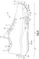
- an article of footwear 10 includes an upper 100 and a sole structure 200.
- the article of footwear 10 may be divided into one or more regions.
- the regions may include a forefoot region 12, a mid-foot region 14, and a heel region 16.
- the forefoot region 12 may be subdivided into a toe portion 12 T corresponding with phalanges, and a ball portion 12 B associated with metatarsal bones of a foot.
- the mid-foot region 14 may correspond with an arch area of the foot, and the heel region 16 may correspond with rear portions of the foot, including a calcaneus bone.
- the footwear 10 may further include an anterior end 18 associated with a forward-most point of the forefoot region 12, and a posterior end 20 corresponding to a rearward-most point of the heel region 16.
- a longitudinal axis A F1 of the footwear 10 extends along a length of the footwear 10 from the anterior end 18 to the posterior end 20, parallel to a ground surface.
- the longitudinal axis A F1 may be centrally located along the length of the footwear 10, such that the longitudinal axis A F1 generally divides the footwear 10 into a medial side 22 and a lateral side 24. Accordingly, the medial side 22 and the lateral side 24 respectively correspond with opposite sides of the footwear 10 and extend through the regions 12, 14, 16. As illustrated in FIGS.
- a lateral axis A F2 of the footwear 10 extends along a width of the footwear 10 from the medial side 22 to the lateral side 24, parallel to a ground surface, such that the lateral axis A F2 is disposed orthogonal to the longitudinal axis A F1 .
- a longitudinal direction refers to the direction extending from the anterior end 18 to the posterior end 20, while a lateral direction refers to the direction transverse to the longitudinal direction and extending from the medial side 22 to the lateral side 24.
- the article of footwear 10, and more particularly, the sole structure 200 may be further described as including a peripheral region 26 and an interior region 28, as illustrated in FIG. 2 .
- the peripheral region 26 is generally described as being a region between the interior region 28 and an outer perimeter of the sole structure 200. Particularly, the peripheral region 26 extends from the forefoot region 12 to the heel region 16 along each of the medial side 22 and the lateral side 24, and wraps around each of the forefoot region 12 and the heel region 16.
- the interior region 28 is circumscribed by the peripheral region 26, and extends from the forefoot region 12 to the heel region 16 along a central portion of the sole structure 200. Accordingly, each of the forefoot region 12, the mid-foot region 14, and the heel region 16 may be described as including the peripheral region 26 and the interior region 28.
- the upper 100 includes interior surfaces 101 that define an interior void 102 configured to receive and secure a foot for support on the sole structure 200.
- the upper 100 may be formed from one or more materials that are stitched or adhesively bonded together to form the interior void 102. Suitable materials of the upper 100 may include, but are not limited to, mesh, textiles, foam, leather, and synthetic leather. The materials may be selected and located to impart properties of durability, air-permeability, wear-resistance, flexibility, and comfort.
- the upper 100 includes a strobel 104 having a bottom surface opposing the sole structure 200 and an opposing top surface defining a footbed 106 of the interior void 102. Stitching or adhesives may secure the strobel to the upper 100.
- the footbed 106 may be contoured to conform to a profile of the bottom surface (e.g., plantar) of the foot.
- the upper 100 may also incorporate additional layers such as an insole 108 or sockliner that may be disposed upon the strobel 104.
- the insole or sockliner 108 may reside within the interior void 102 of the upper 100 and be positioned to receive a plantar surface of the foot to enhance the comfort of the article of footwear 10.
- an ankle opening 114 in the heel region 16 may provide access to the interior void 102.
- the ankle opening 114 may receive a foot to secure the foot within the void 102 and to facilitate entry and removal of the foot from and to the interior void 102.
- one or more fasteners 110 extend along the upper 100 to adjust a fit of the interior void 102 around the foot and to accommodate entry and removal of the foot therefrom.
- the upper 100 may include apertures, such as eyelets and/or other engagement features such as fabric or mesh loops that receive the fasteners 110.
- the fasteners 110 may include laces, straps, cords, hook-and-loop, or any other suitable type of fastener.
- the upper 100 may include a tongue portion 116 that extends between the interior void 102 and the fasteners 110.
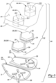
- the sole structure 200 includes a midsole 202 configured to provide cushioning characteristics to the sole structure 200, and one or more outsole members 204 configured to provide a ground-engaging surface 30 of the article of footwear 10.
- the midsole 202 may include a plurality of subcomponents for providing zonal cushioning and performance characteristics.
- the midsole 202 may include a primary member 206 and one or more secondary members or inserts 208. While the secondary members 208 are generally shown and described herein as being fluid-filled bladders 208, the secondary members 208 may have other configurations (e.g., a foam construct) within the scope of the present disclosure.
- the midsole 202 is generally shown and described herein as including two bladders 208, the midsole 202 may include more or less than two bladders 208 within the scope of the present disclosure.
- the primary member 206 extends from a first end 212, which may be disposed at the anterior end 18 of the footwear 10, to a second end 214, which may be disposed at the posterior end 20 of the footwear. Accordingly, the primary member 206 may extend along an entire length of the footwear 10. With reference to FIGS. 3 and 4 , the primary member 206 may further include a top surface 216 and a bottom surface 218 formed on an opposite side of the primary member 206 than the top surface 216. The top surface 216 of the primary member 206 is configured to oppose the strobel 104 of the upper 100, and may be contoured to define a profile of the footbed 106 corresponding to a shape of the foot. As shown in FIG.
- a distance between the top surface 216 and the bottom surface 218 defines a thickness T FE of the primary member 206, which may vary along the length or width of the sole structure 200 (e.g., along the axes A F1 , A F2 ).
- the primary member 206 further includes a peripheral side surface 220 extending between the top surface 216 and the bottom surface 218.
- the peripheral side surface 220 generally defines an outer periphery of the sole structure 200.
- the primary member 206 may include one or more recesses 226 and one or more channels 228.
- the recesses 226 and channels 228 may be formed in the bottom surface 218.
- the recesses 226 may be sized and shaped to receive each bladder 208.
- a first recess 226, 226-1 is formed in the forefoot region 12 of the sole structure 200 on the medial side 22, and a second recess 226, 226-2 is formed in the forefoot region 12 of the sole structure 200 on the lateral side 24.
- the first and second recesses 226-1, 226-2 may be aligned along, or in a direction substantially parallel to (+/- five degrees) the lateral axis A F2 .
- the first and second recesses 226-1, 226-2 may be defined by first and second peripheral surfaces 232-1, 232-2 and first and second intermediate surfaces 234-1, 234-2, respectively.
- the peripheral surfaces 232-1, 232-2 may extend from the bottom surface 218 of the primary member 206 towards the top surface 216.
- the peripheral surfaces 232-1, 232-2 may extend partially from the bottom surface 218 toward the top surface 216 and terminate at the intermediate surfaces 234-1, 234-2, respectively, disposed between the bottom surface 218 and the top surface 216.
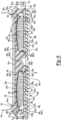
- a depth D R1 , D R2 of the recesses 226-1, 226-2, measured from the bottom surface 218 to the intermediate surfaces 234-1, 234-2, respectively, extends only partially through the thickness T FE of the primary member 206.
- a first channel 228, 228-1 extends from the forefoot region 12 of the sole structure 200 to the heel region 16 of the sole structure 200
- a second channel 228, 228-2 extends from the medial side 22 of the sole structure 200 to the lateral side of the sole structure 200.
- the first channel 228-1 may be aligned with, or extend in a direction substantially parallel to (+/- five degrees)
- the longitudinal axis A F1 may be aligned with, or extend in a direction substantially parallel to (+/five degrees)
- the lateral axis A F2 may be aligned with, or extend in a direction substantially parallel to (+/five degrees
- the longitudinal axis A F1 be disposed between the first recess 226-1 and the second recess 228-2, and the second channel 228-2 may be disposed between the anterior end 18 of the footwear 10 and the first and second recesses 226-1, 226-2.
- the configuration of the first and second channels 228-1, 228-2 may provide increased flexibility and responsiveness relative to the longitudinal and lateral axes A F1 , A F2 as the midsole 202 resiliently compresses under an applied load during use.
- each bladder 208 may be constructed in a similar manner to each other.
- each bladder 208 may include a first barrier layer 238 and a second barrier layer 240 opposing the first barrier layer 238, which can be joined to each other at discrete locations to define a chamber 242 and a peripheral seam 244.
- the first barrier layer 238 and the second barrier layer 240 cooperate to define a geometry (e.g., thicknesses, width, and lengths) of the chamber 242.
- the peripheral seam 244 may bound the periphery of the chamber 242 to seal the fluid (e.g., air) within the chamber 242.
- the chamber 242 is associated with an area of the bladder 208 where interior surfaces of the first barrier layer 238 and the second barrier layer 240 are not joined together and, thus, are separated from one another.
- an outer peripheral profile of the chamber 242 has a cross-sectional shape corresponding to a hexagon, as best shown in FIG. 2 .
- the outer peripheral profile of the chamber 242 may define various other shapes (e.g., round, oval, rounded square, etc.) within the scope of the present disclosure.
- the first and second barrier layers 238, 240 are substantially planar. In other implementations, one or both of the first or second barrier layer 238, 240 is cup-shaped (e.g., concave or convex). As shown in FIGS. 3 and 4 , the second barrier layer 240 opposes the first barrier layer 238 to define a thickness T C of the chamber 242 extending between opposed outer surfaces 246, 248 of the first and second barrier layers 238, 240, respectively.
- the thickness T C may extend in a direction orthogonal to the outer surfaces 246, 248. In some implementations, the thickness T C is equal to the depths D R1 , D R2 of the respective recesses 226-1, 226-2. In other implementations, the thickness T C may be less or greater than the depths D R1 , D R2 of the respective recesses 226-1, 226-2.
- a space formed between opposing interior surfaces of the first barrier layer 238 and the second barrier layer 240 defines an interior void 250 of the chamber 242.
- the interior void 250 of the chamber 242 may receive a tensile element 252 therein.
- Each tensile element 252 may include a series of tensile strands 254 extending between a first tensile sheet 256 and a second tensile sheet 258.
- the first tensile sheet 256 may be attached to the first barrier layer 238 while the second tensile sheet 258 may be attached to the second barrier layer 240.
- the tensile strands 254 of the tensile element 252 are placed in tension. Because the first tensile sheet 256 is attached to the first barrier layer 238 and the second tensile sheet 258 is attached to the second barrier layer 240, the tensile strands 254 retain a desired shape of the bladder 208 when the pressurized fluid is injected into the interior void 250.
- the tensile element 252 maintains substantially planar first and second barrier layers 238, 240.
- the outer surfaces 246, 248 of the bladder 208 which are collectively defined by the barrier layers 238, 240, are also substantially planar.
- the bladders 208 are arranged to provide cushioning in the forefoot region 12 of the sole structure 200.
- the bladders 208 may be disposed within the first and second recesses 226-1, 226-2.
- a first bladder 208, 208-1 may be coupled to one or both of the first peripheral surface 232-1 or the first intermediate surface 20
- a second bladder 208, 208-2 may be coupled to one or both of the second peripheral surface 232-2 or the second intermediate surface 234-2, using various methods of bonding, including adhesively bonding or melding, for example.
- the one or more outsole members 204 include first, second, third, and fourth outsole members 204-1, 204-2, 204-3, 204-4. In other implementations, however, the sole structure 200 may include more or less than four outsole members 204.
- Each outsole member 204 may include an upper surface 260 opposite the ground-engaging surface 30.
- the upper surface 260 and the ground-engaging surface 30 may define a web 261 having a thickness T W extending therebetween and having a plurality of first traction elements 262 (e.g., first protrusions) and one or more second traction elements 264 (e.g., second protrusions).
- the thickness Tw of the web 261 may be constant.
- the thickness T W may not be constant.
- the thickness T W may be smaller in a central region (e.g., the portion that is aligned with the bladders 208) and larger in a peripheral region (e.g., the portion that engages the midsole 202).
- the first traction elements 262 and the second traction elements 264 may each define various shapes and heights protruding from the ground-engaging surface 30.
- the first traction elements 262 may define a square or hexagonal shape and may protrude from the ground-engaging surface 30 by a first height H1
- the second traction elements 264 may define an oblong (e.g., stadium or ellipse) shape and may protrude from the ground-engaging surface 30 by a second height H2.
- one or more of the first traction elements 262 includes a distal end 265 offset from the ground-engaging surface 30 and defining the first height H1
- one or more of the second traction elements 264 includes a distal end 267 offset from the ground-engaging surface 30 and defining the second height H2.
- the second height H2 is greater than the first height H1 and is greater than the thickness T W of the web 261.
- the second height H2 may be 5%-25% greater than the first height H1 and 25%-200% greater than the thickness T W of the web 261.
- the second height H2 may be approximately 0.5 millimeters greater than the first height H1 and approximately 2.25 millimeters greater than the thickness T W of the web 261. Accordingly, during use, the second traction elements 264 may engage a surface of the ground prior to the first traction elements 262, such that the surface of the ground applies a force on the second traction elements 264 prior to applying a force on the first traction elements 262.
- the ratio of the second height H2 to the thickness T W of the web 261 can allow the web 261 to flex upon application of the force on the second traction elements 264 by the surface of the ground.
- the distal ends 265 of the first traction elements 262 are disposed in a first plane P1
- the distal ends 267 of the second traction elements 264 are disposed in a second plane P2.
- the first plane P1 may be disposed between the second plane P2 and the ground-engaging surface 30.
- the first plane P1 is substantially parallel (+/- 5 degrees) to the second plane P1 and/or the ground-engaging surface 30.
- the ground-engaging surface 30 includes eight (8) second traction elements 264.
- the ground-engaging surface 30 of the first outsole member 204-1 may include four (4) second traction elements 264 arranged in a first pattern 266, and the second outsole member 204-2 may include four (4) second traction elements 264 arranged in a second pattern 268.
- the first and second patterns 266, 268 each define an X-shape.
- at least one of the second traction elements 264 may be aligned with the recess(es) 226.
- the first pattern 266 may be aligned with the first recess 226-1
- the second pattern 268 may be aligned with the second recess 226-2.
- the outsole 204 and the subcomponents 206, 208 of the midsole 202 may be assembled and secured to each other using various methods of bonding, including adhesively bonding and melding, for example. As described in greater detail below, the outsole 204 may be overmolded onto the subcomponents 206, 208 of the midsole 202, such that the midsole 202 defines a profile of the ground-engaging surface 30 of the footwear 10. Alternatively, the outsole 204 may be bonded to the midsole 202 using an adhesive or other suitable attachment method.
- the relationship of the second height H2 of the second traction elements 264 to the first height H1 of the first traction elements 262 can allow the second traction elements 264 to engage a surface of the ground before the first traction elements 262 engage the ground, such that the surface of the ground applies a force on the second traction elements 264 prior to applying a force on the first traction elements 262.
- the force applied by the ground on the second traction elements 264 may be greater than the force applied by the ground on the first traction elements 262.
- the relationship between the second height H2 to the thickness T W of the web 261 can allow the web 261 to efficiently flex upon application of the force on the second traction elements 264 by the ground, such that the force is efficiently transmitted through the second traction elements 264 onto the bladder 208.
- the bladder 208 is essentially subjected to a form of a point load by the second traction elements 264, thereby reducing the force required to load and deform the bladder 208.
- the load required to load and deform the bladder 208 is reduced in comparison to a load that is evenly applied across an entire surface of the bladder 208.
- higher-pressure bladders 208 may be incorporated into sole structures intended for use with lighter-weight individuals such as children.
- a sole structure 200c for use with an article of footwear e.g., article of footwear 10.
- the sole structure 200c may be used with, and attached to, the upper 100 of the article of footwear 10 in place of the sole structure 200.
- like reference numerals are used hereinafter and in the drawings to identify like components while like reference numerals containing letter extensions (e.g., "c") are used to identify those components that have been modified.
- the sole structure 202c includes one or more outsole members 204c-1, 204c-2...204c-n coupled to a midsole 202c.
- the outsole 204c and the midsole 202c may be assembled and secured to each other using various methods of bonding, including adhesively bonding and melding, for example.
- the outsole 204c may be overmolded onto the subcomponents 206c, 208c of the midsole 202c, such that the midsole 202c defines a profile of the ground-engaging surface 30 of the footwear 10.
- the outsole 204c may be bonded to the midsole 202c using an adhesive or other suitable attachment method.
- the upper surface 260c of the first outsole member 204c-1 may include a plurality of protrusions 270.
- the protrusions 270 may each define various shapes and heights protruding from the upper surface 260c.
- the protrusions 270 may define an oblong (e.g., stadium or ellipse) shape.
- the upper surface 260c includes eight protrusions 270.
- the upper surface 260c of the first outsole member 204c-1 may include four elongate protrusions 270 arranged in a first pattern 272c
- the upper surface 260c of the second outsole member 204c-2 may include four elongate protrusions 270 arranged in a second pattern 274c.
- the first and second patterns 272c, 274c each define an X-shape.
- the first and second patterns 272c, 274c of the protrusions 270 may be the same as the first and second patterns 266c, 268c of the second traction elements 268c.
- the size, shape, and arrangement of the protrusions 270 may be the same as the size, shape, and arrangement of the second traction elements 268c, such that each protrusion 270 is aligned with one of the second traction elements 268c. Accordingly, as will be described in more detail below, in the assembled configuration, at least one of the protrusions 270 may be aligned with the recess(es) 226c and, thus, the bladder 208 disposed therein.
- the first pattern 272c may be aligned with the first recess 226c-1
- the second pattern 274c may be aligned with the second recess 226c-2.
- the first patterns 266c, 272c may be aligned with the first recess 226c-1, and the second patterns 268c, 274c may be aligned with the second recess 226c-2, as previously described, to provide localized cushioning characteristics to the sole structure 200c.
- one or more of the protrusions 270 may engage the bladder(s) 208c (e.g., the second barrier layer 240c), such that the upper surface 260c is spaced apart from the bladder(s) 208c.
- the upper surface 260c and the second barrier layer 240c may define a void 278c surrounding the protrusions 270c.
- At least a portion of one or more of the protrusions 270 is disposed within the first recess 226c-1 or optionally the second recess 226c-2.
- at least a portion of each protrusion 270 may be disposed between the bottom surface 218c of the midsole 202c and the intermediate surface 234c-1, 234c-2 of one of the first or second recesses 226c-1, 226c-2, respectively.
- the cushioning and performance properties of the bladder 208c are effectively and efficiently imparted to the ground-engaging surface 30.
- forces associated with pushing off of the forefoot during running or jumping motions may be more efficiently absorbed by the bladder 208c, as such forces will first be imparted onto the bladder 208c by the protrusions 270, effectively reducing the amount of force required to deflect the second barrier layer 240c of the bladder 208c.
- the height of the second traction elements 264c and the height of the first traction elements 262c are substantially similar, such that the surface of the ground simultaneously applies a force on the second traction elements 264c and the first traction elements 262c.
- the force applied by the ground on the second traction elements 264c may be substantially similar as the force applied by the ground on the first traction elements 262c.
- the force upon application of the force on the second traction elements 264c by the ground, the force is efficiently transmitted through the second traction elements 264c to the protrusions 270 and imparted onto the bladder 208c by the protrusions 270.
- an article of footwear 10a is provided and includes the upper 100 and a sole structure 200a attached to the upper 100.
- like reference numerals are used hereinafter and in the drawings to identify like components while like reference numerals containing letter extensions are used to identify those components that have been modified.
- the sole structure 200a includes a midsole 202a configured to provide cushioning characteristics to the sole structure 200a, and one or more of the outsole members 204a configured to provide a ground-engaging surface 30 of the article of footwear 10a.
- the midsole 202a may include a plurality of subcomponents for providing zonal cushioning and performance characteristics.
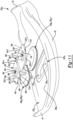
- the midsole 202a may include a primary member 206a, one or more secondary members or inserts 208a, and one or more actuation members 280.
- the secondary members 208a are generally shown and described herein as being fluid-filled bladders 208a, the secondary members 208a may have other configurations (e.g., a foam construct) within the scope of the present disclosure.
- the midsole 202a is generally shown and described herein as including two bladders 208a, the midsole 202a may include more or less than two bladders 208a within the scope of the present disclosure.
- the primary member 206a extends from a first end 212a, which may be disposed at the anterior end 18 of the footwear 10a, to a second end 214a, which may be disposed at the posterior end 20 of the footwear 10a. Accordingly, the primary member 206a may extend along an entire length of the footwear 10a. With reference to FIG. 10 , the primary member 206a may further include a top surface 216a and a bottom surface 218a formed on an opposite side of the primary member 206a than the top surface 216a.
- the top surface 216a of the primary member 206a is configured to oppose the strobel 104 of the upper 100, and may be contoured to define a profile of the footbed 106 corresponding to a shape of the foot. As shown in FIG. 10 , a distance between the top surface 216a and the bottom surface 218a defines a thickness Ta FE of the primary member 206a, which may vary along the length or width of the sole structure 200a (e.g., along the axes A F1 , A F2 ).
- the primary member 206a further includes a peripheral side surface 220a extending between the top surface 216a and the bottom surface 218a.
- the peripheral side surface 220a generally defines an outer periphery of the sole structure 200a.
- the primary member 206a may include one or more recesses 226a formed in the top surface 216a.
- the recesses 226a may be sized and shaped to receive each bladder 208a.
- the primary member 206a includes a single recess 226a formed in the forefoot region 12 of the sole structure 200a between the medial side 22 and the lateral side 24.
- the recess 226a may be aligned along, or in a direction substantially parallel to (+/- five degrees) the lateral axis A F2 .
- the recess 226a may be defined by a peripheral surface 232a and an intermediate surface 234a.
- the peripheral surface 232a may extend from the top surface 216a of the primary member 206a towards the bottom surface 218a.
- the peripheral surface 232a may extend partially from the top surface 216a towards the bottom surface 218a and terminate at the intermediate surface 234a, disposed between the bottom surface 218a and the top surface 216a.
- a depth Da R1 of the recess 226a measured from the top surface 216a to the intermediate surface 234a, extends only partially through the thickness Ta FE of the primary member 206a.
- Each bladder 208a may include a first barrier layer 238a and a second barrier layer 240a opposing the first barrier layer 238a.
- the first barrier layer 238a and the second barrier layer 240a can be joined to each other at discrete locations to define a chamber 242a and a peripheral seam 244a.
- the first barrier layer 238a and the second barrier layer 240a cooperate to define a geometry (e.g., thicknesses, width, and lengths) of the chamber 242a.
- the peripheral seam 244a may bound the periphery of the chamber 242a to seal the fluid (e.g., air) within the chamber 242a.
- the chamber 242a is associated with an area of the bladder 208a where interior surfaces of the first barrier layer 238a and the second barrier layer 240a are not joined together and, thus, are separated from one another.
- an outer peripheral profile of the chamber 242a has a rounded cross-sectional shape, as best shown in FIG. 11 .
- the outer peripheral profile of the chamber 242a may define various other shapes (e.g., circular, oval, rounded square, etc.) within the scope of the present disclosure.
- the second barrier layer 240a opposes the first barrier layer 238a to define a thickness Tac of the chamber 242a extending between opposed outer surfaces 246a, 248a of the first and second barrier layers 238a, 240a, respectively.
- the thickness Tac may extend in a direction orthogonal to the outer surfaces 246a, 248a.
- the thickness Tac is equal to the depth Da R1 of the recess 226a. In other implementations, the thickness Tac may be less than the depth Da R1 the recess 226a.
- first barrier layer 238a e.g., the outer surface 246a
- second barrier layer 240a e.g., the outer surface 248a
- first or second barrier layer 238a, 240a is cup-shaped (e.g., concave or convex).
- a space formed between opposing interior surfaces of the first barrier layer 238a and the second barrier layer 240a defines an interior void 250a of the chamber 242a.
- the interior void 250a of the chamber 242a may receive the tensile element 252 therein in the manner previously described.
- the bladders 208a are arranged to provide cushioning in the forefoot region 12 of the sole structure 200a.
- the bladders 208a may be disposed within the recess 226a.
- a first bladder 208a, 208a-1 may be coupled to one or both of the peripheral surface 232a or the intermediate surface 234a
- a second bladder 208a, 208a-2 may be coupled to one or both of the peripheral surface 232a or the intermediate surface 234a, using various methods of bonding, including adhesively bonding or melding, for example.
- one or more outsole members 204a-1, 204a-2...204a-n may be coupled to the midsole 202a.
- the outsole 204a and the midsole 202a may be assembled and secured to each other using various methods of bonding, including adhesively bonding and melding, for example.
- the outsole 204a may be overmolded onto the subcomponents 206a, 208a of the midsole 202a, such that the midsole 202a defines a profile of the ground-engaging surface 30 of the footwear 10a.
- the outsole 204a may be bonded to the midsole 202a using an adhesive or other suitable attachment method.
- the actuation member 280 may include a lateral portion 282, a medial portion 284, and a central portion 286 extending between the lateral portion 282 and the medial portion 284.
- the lateral portion 282 may include a lateral upper surface 288, a lateral lower surface 290 opposite the lateral upper surface 288, and a lateral peripheral surface 292 extending from the lateral upper surface 288 to the lateral lower surface 290.
- the lateral portion 282 may further include a lateral protrusion 294 extending from the lateral lower surface 290, and a corresponding lateral recess 296 disposed within the lateral upper surface 288 and aligned with the lateral protrusion 294.
- the lateral lower surface 290 may include a convex portion 298 corresponding to the lateral protrusion 294, and the lateral upper surface 288 may include a concave portion 300 aligned with the convex portion 298.
- the convex portion 298 and/or the concave portion 300 define a portion of a sphere (e.g., a semispherical shape).
- the lateral peripheral surface 292 may include a front segment 302-1, a rear segment 302-2, a lateral segment 302-3, and a medial segment 302-4.
- the front and rear segments 302-1, 302-2 may extend linearly and define an angle ⁇ therebetween.
- the angle ⁇ is equal to zero degrees, such that the front segment 302-1 is parallel to the rear segment 302-2.
- the angle ⁇ is greater than zero degrees (e.g., between one degree and ten degrees), such that the distance between the front and rear segments 302-1, 302-2 is less proximate the lateral segment 302-3 than it is proximate the medial segment 302-4.
- the lateral segment 302-3 may extend arcuately from the front segment 302-1 to the rear segment 302-2, while the medial segment 302-4 may extend linearly from the front segment 302-1 to the rear segment 302-2.
- the medial portion 284 may include a medial upper surface 306, a medial lower surface 308 opposite the medial upper surface 306, and a medial peripheral surface 310 extending from the medial upper surface 306 to the medial lower surface 308.
- the medial portion 284 may further include a medial protrusion 320 extending from the medial lower surface 308, and a corresponding medial recess 312 disposed within the medial upper surface 306 and aligned with the medial protrusion 310.
- the medial lower surface 308 may include a convex portion 314 corresponding to the medial protrusion 320
- the medial upper surface 306 may include a concave portion 316 aligned with the convex portion 314.
- the convex portion 314 and/or the concave portion 316 define a portion of a sphere (e.g., a semispherical shape).
- the medial peripheral surface 310 may include a front segment 318-1, a rear segment 318-2, a lateral segment 318-3, a first medial segment 318-4, and a second medial segment 318-5.
- the front and rear segments medial segment 318-1, 318-2 may extend linearly and define an angle ⁇ therebetween. In some implementations, the angle ⁇ is equal to zero degrees, such that the front segment 318-1 is parallel to the rear segment 318-2.
- the angle ⁇ is greater than zero degrees (e.g., between one degree and ten degrees), such that the distance between the front and rear segments 318-1, 318-2 is less proximate the lateral segment 318-3 than it is proximate the medial segments 318-4, 318-5.
- the angle ⁇ is substantially equal to the angle ⁇ such that the front segment 302-1 is collinear with the front segment 318-1, and the rear segment 302-2 is collinear with the rear segment 318-2.
- the lateral segment 318-3 and the first medial segment 318-4 may extend linearly from the front segment 318-1 to the rear segment 318-2, while the second medial segment 318-5 may extend arcuately from the front segment 318-1 to the rear segment 318-2.
- the central portion 286 of the actuation member 280 may connect the lateral portion 282 to the medial portion 284. As illustrated in FIG. 10 , in some implementations, the central portion 286 defines a U-shaped cross section in a plane extending perpendicular to the longitudinal and lateral axes A F1 , A F2 of the footwear 10a. In some implementations, the central portion 286 extends below the lateral and medial lower surfaces 290, 308 of the lateral and medial portions 282, 284, respectively, such that the lower surfaces 290, 308 are disposed between the upper surfaces 288, 306 and the central portion 286 in a direction transverse to the axes A F1 , A F2 of the footwear 10a.
- the central portion 286 may be disposed between the medial and lateral sides 22, 24 of the footwear 10a.
- the central portion 286 may be disposed between the bladders 208a and aligned with the longitudinal axis A F1 of the footwear 10a in the assembled configuration.
- the actuation member 280 may be constructed at least in part from a flexible and/or resilient material that allows the medial portion 284 to flex and move relative to the lateral portion 282 during use of the footwear 10a.
- the cushioning and performance properties of the bladders 208a are effectively and efficiently imparted to the ground-engaging surface 30.
- forces associated with pushing off of the forefoot during running or jumping motions may be more efficiently absorbed by the bladders 208a, as such forces will first be imparted onto the bladders 208a by the protrusions 294, 310, effectively reducing the amount of force required to deflect the first barrier layers 238a of the bladders 208a.
- an article of footwear 10b is provided and includes the upper 100 and a sole structure 200b attached to the upper 100.
- like reference numerals are used hereinafter and in the drawings to identify like components while like reference numerals containing letter extensions are used to identify those components that have been modified.
- the sole structure 200b includes a midsole 202b configured to provide cushioning characteristics to the sole structure 200b, and one or more of the outsole members 204b configured to provide a ground-engaging surface 30 of the article of footwear 10b.
- the midsole 202b may include a plurality of subcomponents for providing zonal cushioning and performance characteristics.
- the midsole 202b may include the primary member 206b, one or more secondary members or inserts 208b, and one or more actuation members 280b.
- the secondary members 208b are generally shown and described herein as being fluid-filled bladders 208b, the secondary members 208b may have other configurations (e.g., a foam construct) within the scope of the present disclosure.
- the midsole 202b is generally shown and described herein as including a single bladder 208b, the midsole 202b may include more or less than one bladder 208b within the scope of the present disclosure.
- the bladder 208b may include a first barrier layer 238b and a second barrier layer 240b opposing the first barrier layer 238b, which can be joined to each other at discrete locations to define a chamber 242b and a peripheral seam 244b.
- the first barrier layer 238b and the second barrier layer 240b cooperate to define a geometry (e.g., thicknesses, width, and lengths) of the chamber 242b.
- the peripheral seam 244b may bound the periphery of the chamber 242b to seal the fluid (e.g., air) within the chamber 242b.
- an outer peripheral profile of the chamber 242b has an elongate cross-sectional shape (e.g., stadium shape), and includes a first tab 322 extending towards the anterior end 18 of the sole structure 200b, and a second tab 324 extending toward the posterior end 20 of the sole structure 200b, as best shown in FIG. 13 .
- the first tab 324 is disposed within a recess 326 of the primary member 206b, and the shape of the first tab 324 corresponds to the shape of the recess 326.
- the outer peripheral profile of the chamber 242b may define various other shapes (e.g., circular, oval, rounded square, etc.) within the scope of the present disclosure.
- the second barrier layer 240b opposes the first barrier layer 238b to define a thickness The of the chamber 242b extending between opposed outer surfaces 246b, 248b of the first and second barrier layers 238b, 240b, respectively.
- the thickness The may extend in a direction orthogonal to the outer surfaces 246b, 248b.
- the thickness The is equal to the depth Db R1 of the recess 226b. In other implementations, the thickness The may be less than the depth Db R1 the recess 226b.
- the first barrier layer 238b (e.g., the outer surface 246b) is cup-shaped (e.g., concave), while the second barrier layer 240b (e.g., the outer surface 248b) is substantially planar.
- the first or second barrier layer 238b, 240b e.g., the outer surfaces 246b, 248b
- the first or second barrier layer 238b, 240b is cup-shaped (e.g., concave or convex).
- a space formed between opposing interior surfaces of the first barrier layer 238b and the second barrier layer 240b defines an interior void 250b of the chamber 242b.
- the interior void 250b of the chamber 242b may receive the tensile element 252 therein in the manner previously described.
- the bladder 208b is arranged to provide cushioning in the forefoot region 12 of the sole structure 200b.
- the bladder 208b may be disposed within the recess 226b.
- the bladder 208b may be coupled to one or both of the peripheral surface 232b or the intermediate surface 234b using various methods of bonding, including adhesively bonding or melding, for example.
- one or more of the outsole members 204b-1, 204b-2...204b-n may be coupled to the midsole 202b.
- the outsole 204b and the midsole 202b may be assembled and secured to each other using various methods of bonding, including adhesively bonding and melding, for example.
- the outsole 204b may be overmolded onto the subcomponents 206b, 208b of the midsole 202b, such that the midsole 202b defines a profile of the ground-engaging surface 30 of the footwear 10b.
- the outsole 204b may be bonded to the midsole 202b using an adhesive or other suitable attachment method.
- the actuation member 280b may include an elongated central portion 286b extending between a lateral side 282 and a medial side 332.
- the actuation member 280b may include an upper surface 334, a lower surface 338 opposite the upper surface 334, and a peripheral surface 336 extending from the upper surface 334 to the lower surface 338.
- the central portion 286b may include an elongated protrusion 340 extending from the lower surface 338, and a corresponding recess 342 disposed within the upper surface 334 and aligned within the protrusion 340.
- the lower surface 338 may include a convex portion 344 corresponding to the protrusion 340, and the upper surface 334 may include a concave portion 346 aligned with the convex portion 344.
- the convex portion 344 and/or the concave portion 346 define an oblong (e.g., stadium or ellipse) shape.
- the peripheral surface 336 may include a front segment 302b-1, a rear segment 302b-2, a lateral segment 302b-3, and a medial segment 302b-4.
- the front and rear segments 302b-1, 302b-2 may extend linearly and define an angle ⁇ therebetween.
- the angle ⁇ is equal to zero degrees, such that the front segment 302b-1 is parallel to the rear segment 302b-2.
- the angle ⁇ is greater than zero degrees (e.g., between one degree and ten degrees), such that the distance between the front and rear segments 302b-1, 302b-2 is less proximate the lateral segment 302b-3 than it is proximate the medial segment 302b-4.
- the lateral segment 302b-3 may extend arcuately from the front segment 302-1 to the rear segment 302-2, and the medial segment 302b-4 may extend arcuately from the front segment 302b-1 to the rear segment 302b-2.
- the central portion 286b may be disposed between the medial and lateral sides 22, 24 of the footwear 10b.
- the central portion 286b may be aligned with the longitudinal axis A F2 of the footwear 10b in the assembled configuration.
- the actuation member 280b may be constructed at least in part from a flexible and/or resilient material that allows the medial side 330 to flex and move relative to the lateral side 332 during use of the footwear 10b.
- the cushioning and performance properties of the bladder 208b are effectively and efficiently imparted to the ground-engaging surface 30.
- forces associated with pushing off of the forefoot during running or jumping motions may be more efficiently absorbed by the bladder 208b, as such forces will first be imparted onto the bladder 208b by the protrusion 340, effectively reducing the amount of force required to deflect the first barrier layers 238b of the bladder 208b.
Landscapes
- Chemical & Material Sciences (AREA)
- Engineering & Computer Science (AREA)
- Materials Engineering (AREA)
- Footwear And Its Accessory, Manufacturing Method And Apparatuses (AREA)
Description
- The present disclosure relates generally to a sole structure for an article of footwear, and more particularly to a sole structure including an outsole having a chamber-engaging member.
- This section provides background information related to the present disclosure and is not necessarily prior art.
- Articles of footwear conventionally include an upper and a sole structure. The upper may be formed from any suitable material(s) to receive, secure, and support a foot on the sole structure. The upper may cooperate with laces, straps, or other fasteners to adjust the fit of the upper around the foot. A bottom portion of the upper, proximate to a bottom surface of the foot, attaches to the sole structure.
- Sole structures generally include a layered arrangement extending between a ground surface and the upper. One layer of the sole structure includes an outsole that provides abrasion-resistance and traction with the ground surface. The outsole may be formed from rubber or other materials that impart durability and wear-resistance, as well as enhance traction with the ground surface. Another layer of the sole structure includes a midsole disposed between the outsole and the upper. The midsole provides cushioning for the foot and may be partially formed from a polymer foam material that compresses resiliently under an applied load to cushion the foot by attenuating ground-reaction forces. The midsole may additionally or alternatively incorporate a fluid-filled bladder to provide cushioning to the foot by compressing resiliently under an applied load to attenuate ground-reaction forces. Sole structures may also include a comfort-enhancing insole or sockliner located within a void proximate to the bottom portion of the upper and a strobel attached to the upper and disposed between the midsole and the insole or sockliner.
- Midsoles employing fluid-filled bladders typically include a recess sized and shaped to receive a similarly sized and shaped fluid-filled bladder. The fluid-filled bladders are often constructed to both flex and provide support when compressed resiliently under applied loads, such as during athletic movements. In this regard, fluid-filled bladders are often designed to balance support for the foot with cushioning characteristics that provide responsiveness as the bladder resiliently compresses under an applied load.
-
WO 2019/118533 A1 describes a sole structure for an article of footwear having an upper includes a heel region, a forefoot region, and a mid-foot region disposed between the heel region and the forefoot region. The sole structure also includes a bladder including a first barrier layer cooperating with a second barrier layer to define a first chamber bounding a periphery of the heel region, and a second chamber extending from the mid-foot region through the forefoot region and including a plurality of segments extending from a medial side of the sole structure to a lateral side of the sole structure. Each of the segments of the second chamber includes a medial reservoir adjacent to the medial side and a lateral reservoir adjacent to the lateral side, the medial reservoir fluidly coupled to the lateral reservoir via a first conduit. - The claimed invention is defined by the features in independent claims. Particular embodiments are defined in dependent claims.
- The drawings described herein are for illustrative purposes only of selected configurations and are not intended to limit the scope of the present disclosure.
-
FIG. 1 is a side elevation view of an article of footwear in accordance with principles of the present disclosure; -
FIG. 2 is bottom plan view of a sole structure of the article of footwear ofFIG. 1 ; -
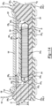
FIG. 3 is a cross-sectional view of the sole structure ofFIG. 2 , taken along line 3-3 ofFIG. 2 corresponding to a lateral axis of the sole structure; -
FIG. 4 is a cross-sectional view of the sole structure ofFIG. 2 , taken along line 4-4 ofFIG. 2 and corresponding to a longitudinal axis of the sole structure; -
FIG. 5 is an exploded top perspective view of a portion of the sole structure ofFIG. 2 ; -
FIG. 6 is a cross-sectional view of another sole structure for an article of footwear in accordance with principles of the present disclosure, the cross section taken along a line corresponding to a lateral axis of the sole structure; -
FIG. 7 is a top perspective view of a portion of an outsole of the sole structure ofFIG. 6 ; -
FIG. 8 is a side elevation view of another article of footwear in accordance with principles of the present disclosure; -
FIG. 9 is a top plan view of a sole structure of the article of footwear ofFIG. 8 ; -
FIG. 10 is a cross-sectional view of the sole structure ofFIG. 9 , taken along line 10-10 ofFIG. 9 corresponding to a lateral axis of the sole structure; -
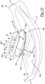
FIG. 11 is an exploded top perspective view of the sole structure ofFIG. 9 ; -
FIG. 12 is a side elevation view of another article of footwear in accordance with principles of the present disclosure; -
FIG. 13 is a top plan view of a sole structure of the article of footwear ofFIG. 12 ; -
FIG. 14 is a cross-sectional view of the sole structure ofFIG. 13 , taken along line 14-14 ofFIG. 13 corresponding to a lateral axis of the sole structure; and -
FIG. 15 is an exploded top perspective view of the sole structure ofFIG. 13 . - Corresponding reference numerals indicate corresponding parts throughout the drawings.
- The claimed invention is defined by the sole structure of
claim 1 and the sole structure of claim 9. Preferred embodiments are defined in the dependent claims. - Example configurations will now be described more fully with reference to the accompanying drawings. Example configurations are provided so that this disclosure will be thorough, and will fully convey the scope of the disclosure to those of ordinary skill in the art. Specific details are set forth such as examples of specific components, devices, and methods, to provide a thorough understanding of configurations of the present disclosure. It will be apparent to those of ordinary skill in the art that specific details need not be employed, that example configurations may be embodied in many different forms, and that the specific details and the example configurations should not be construed to limit the scope of the disclosure.
- The terminology used herein is for the purpose of describing particular exemplary configurations only and is not intended to be limiting. As used herein, the singular articles "a," "an," and "the" may be intended to include the plural forms as well, unless the context clearly indicates otherwise. The terms "comprises," "comprising," "including," and "having," are inclusive and therefore specify the presence of features, steps, operations, elements, and/or components, but do not preclude the presence or addition of one or more other features, steps, operations, elements, components, and/or groups thereof. The method steps, processes, and operations described herein are not to be construed as necessarily requiring their performance in the particular order discussed or illustrated, unless specifically identified as an order of performance. Additional or alternative steps may be employed.
- When an element or layer is referred to as being "on," "engaged to," "connected to," "attached to," or "coupled to" another element or layer, it may be directly on, engaged, connected, attached, or coupled to the other element or layer, or intervening elements or layers may be present. In contrast, when an element is referred to as being "directly on," "directly engaged to," "directly connected to," "directly attached to," or "directly coupled to" another element or layer, there may be no intervening elements or layers present. Other words used to describe the relationship between elements should be interpreted in a like fashion (e.g., "between" versus "directly between," "adjacent" versus "directly adjacent," etc.). As used herein, the term "and/or" includes any and all combinations of one or more of the associated listed items.
- The terms first, second, third, etc. may be used herein to describe various elements, components, regions, layers and/or sections. These elements, components, regions, layers and/or sections should not be limited by these terms. These terms may be only used to distinguish one element, component, region, layer or section from another region, layer or section. Terms such as "first," "second," and other numerical terms do not imply a sequence or order unless clearly indicated by the context. Thus, a first element, component, region, layer or section discussed below could be termed a second element, component, region, layer or section without departing from the teachings of the example configurations.
- In one configuration, a sole structure for an article of footwear includes a midsole having a top surface and a bottom surface opposite the top surface, the bottom surface including a first recess. A first bladder is disposed within the first recess and a first outsole member is coupled to the midsole and includes a ground-engaging surface having a first traction element and a second traction element. The first traction element is aligned with the first bladder and defines a first height relative to the ground-engaging surface, the second traction element is aligned with the first bladder and defines a second height relative to the ground-engaging surface, the second height being greater than the first height.
- The first outsole member includes at least one protrusion which may engage the first bladder and where at least a portion of the at least one protrusion is disposed within the first recess. Further, the at least one protrusion may include a first protrusion that is aligned with the second traction element.
- In one configuration, (i) the first outsole member may include an upper surface facing the first bladder, (ii) the first recess may define a first depth extending in a direction perpendicular to the upper surface, and (iii) the first bladder may define a third height extending in a direction perpendicular to the upper surface, the third height being less than or equal to the first depth.
- The first outsole member may include an upper surface facing the first bladder, whereby the upper surface is spaced apart from the first bladder. The upper surface may extend across the first recess. Further, (i) the second traction element may include a second size and shape and (ii) the ground-engaging surface may include a third traction element having a third size and shape, the second size and shape being the same as the third size and shape.
- In one configuration, the bottom surface may include a second recess having a second bladder disposed therein. A second outsole member may be coupled to the midsole and may include at least one protrusion engaging the second bladder. The first recess and the second recess may be disposed along a line extending parallel to a lateral axis of the sole structure.
- In another configuration, a sole structure for an article of footwear includes a midsole having a top surface and a bottom surface opposite the top surface, the bottom surface including a first recess. A first bladder is disposed within the first recess and a first outsole member is coupled to the midsole and includes a ground-engaging surface having a plurality of first traction elements and a plurality of second traction elements. The plurality of first traction elements each include a first distal end offset from the ground-engaging surface and disposed in a first plane. The plurality of second traction elements each include a second distal end offset from the ground-engaging surface and disposed in a second plane with the first plane being offset from the second plane.
- The first outsole member includes at least one protrusion which may engage the first bladder. At least a portion of the at least one protrusion is disposed within the first recess.
- In one configuration, (i) the first outsole member may include an upper surface facing the first bladder, (ii) the first recess may define a first depth extending in a direction perpendicular to the first upper surface, and (iii) the first bladder may define a first height extending in a direction perpendicular to the first upper surface, the first height being less than or equal to the first depth. The first upper surface may extend across the first recess.
- In one configuration, the first outsole member may include a ground-engaging surface having a first traction element aligned with the first recess. Further, (i) the first traction element may include a first size and shape and (ii) the first outsole member may include a first protrusion engaging the first bladder and having a second size and shape, the first size and shape being the same as the second size and shape. The first traction element may be aligned with the first protrusion.
- The bottom surface may include a second recess and a second bladder disposed within the second recess. A second outsole member having a second upper surface may be coupled to the midsole, the second upper surface facing, and spaced apart from, the second bladder. The first recess and the second recess may be disposed along a line extending parallel to a lateral axis of the sole structure.
- Referring to
FIG. 1 , an article offootwear 10 includes an upper 100 and asole structure 200. The article offootwear 10 may be divided into one or more regions. The regions may include aforefoot region 12, amid-foot region 14, and aheel region 16. Theforefoot region 12 may be subdivided into atoe portion 12T corresponding with phalanges, and aball portion 12B associated with metatarsal bones of a foot. Themid-foot region 14 may correspond with an arch area of the foot, and theheel region 16 may correspond with rear portions of the foot, including a calcaneus bone. - The
footwear 10 may further include ananterior end 18 associated with a forward-most point of theforefoot region 12, and aposterior end 20 corresponding to a rearward-most point of theheel region 16. A longitudinal axis AF1 of thefootwear 10 extends along a length of thefootwear 10 from theanterior end 18 to theposterior end 20, parallel to a ground surface. The longitudinal axis AF1 may be centrally located along the length of thefootwear 10, such that the longitudinal axis AF1 generally divides thefootwear 10 into amedial side 22 and alateral side 24. Accordingly, themedial side 22 and thelateral side 24 respectively correspond with opposite sides of thefootwear 10 and extend through theregions FIGS. 2 and3 , a lateral axis AF2 of thefootwear 10 extends along a width of thefootwear 10 from themedial side 22 to thelateral side 24, parallel to a ground surface, such that the lateral axis AF2 is disposed orthogonal to the longitudinal axis AF1. As used herein, a longitudinal direction refers to the direction extending from theanterior end 18 to theposterior end 20, while a lateral direction refers to the direction transverse to the longitudinal direction and extending from themedial side 22 to thelateral side 24. - The article of
footwear 10, and more particularly, thesole structure 200, may be further described as including aperipheral region 26 and aninterior region 28, as illustrated inFIG. 2 . Theperipheral region 26 is generally described as being a region between theinterior region 28 and an outer perimeter of thesole structure 200. Particularly, theperipheral region 26 extends from theforefoot region 12 to theheel region 16 along each of themedial side 22 and thelateral side 24, and wraps around each of theforefoot region 12 and theheel region 16. Theinterior region 28 is circumscribed by theperipheral region 26, and extends from theforefoot region 12 to theheel region 16 along a central portion of thesole structure 200. Accordingly, each of theforefoot region 12, themid-foot region 14, and theheel region 16 may be described as including theperipheral region 26 and theinterior region 28. - The upper 100 includes
interior surfaces 101 that define aninterior void 102 configured to receive and secure a foot for support on thesole structure 200. The upper 100 may be formed from one or more materials that are stitched or adhesively bonded together to form theinterior void 102. Suitable materials of the upper 100 may include, but are not limited to, mesh, textiles, foam, leather, and synthetic leather. The materials may be selected and located to impart properties of durability, air-permeability, wear-resistance, flexibility, and comfort. - With reference to
FIGS. 3 and 4 , in some examples, the upper 100 includes astrobel 104 having a bottom surface opposing thesole structure 200 and an opposing top surface defining afootbed 106 of theinterior void 102. Stitching or adhesives may secure the strobel to the upper 100. Thefootbed 106 may be contoured to conform to a profile of the bottom surface (e.g., plantar) of the foot. Optionally, the upper 100 may also incorporate additional layers such as aninsole 108 or sockliner that may be disposed upon thestrobel 104. The insole orsockliner 108 may reside within theinterior void 102 of the upper 100 and be positioned to receive a plantar surface of the foot to enhance the comfort of the article offootwear 10. Referring again toFIG. 1 , anankle opening 114 in theheel region 16 may provide access to theinterior void 102. For example, theankle opening 114 may receive a foot to secure the foot within thevoid 102 and to facilitate entry and removal of the foot from and to theinterior void 102. - In some examples, one or
more fasteners 110 extend along the upper 100 to adjust a fit of theinterior void 102 around the foot and to accommodate entry and removal of the foot therefrom. The upper 100 may include apertures, such as eyelets and/or other engagement features such as fabric or mesh loops that receive thefasteners 110. Thefasteners 110 may include laces, straps, cords, hook-and-loop, or any other suitable type of fastener. The upper 100 may include atongue portion 116 that extends between theinterior void 102 and thefasteners 110. - With reference to
FIGS. 1-4 , thesole structure 200 includes amidsole 202 configured to provide cushioning characteristics to thesole structure 200, and one ormore outsole members 204 configured to provide a ground-engagingsurface 30 of the article offootwear 10. As illustrated inFIGS. 3 and 4 , themidsole 202 may include a plurality of subcomponents for providing zonal cushioning and performance characteristics. For example, themidsole 202 may include aprimary member 206 and one or more secondary members or inserts 208. While thesecondary members 208 are generally shown and described herein as being fluid-filledbladders 208, thesecondary members 208 may have other configurations (e.g., a foam construct) within the scope of the present disclosure. Similarly, while themidsole 202 is generally shown and described herein as including twobladders 208, themidsole 202 may include more or less than twobladders 208 within the scope of the present disclosure. - As illustrated in
FIG. 1 , theprimary member 206 extends from afirst end 212, which may be disposed at theanterior end 18 of thefootwear 10, to asecond end 214, which may be disposed at theposterior end 20 of the footwear. Accordingly, theprimary member 206 may extend along an entire length of thefootwear 10. With reference toFIGS. 3 and 4 , theprimary member 206 may further include atop surface 216 and abottom surface 218 formed on an opposite side of theprimary member 206 than thetop surface 216. Thetop surface 216 of theprimary member 206 is configured to oppose thestrobel 104 of the upper 100, and may be contoured to define a profile of thefootbed 106 corresponding to a shape of the foot. As shown inFIG. 4 , a distance between thetop surface 216 and thebottom surface 218 defines a thickness TFE of theprimary member 206, which may vary along the length or width of the sole structure 200 (e.g., along the axes AF1, AF2). - The
primary member 206 further includes aperipheral side surface 220 extending between thetop surface 216 and thebottom surface 218. Theperipheral side surface 220 generally defines an outer periphery of thesole structure 200. - As illustrated in
FIGS. 2 and3 , theprimary member 206 may include one ormore recesses 226 and one or more channels 228. For example, therecesses 226 and channels 228 may be formed in thebottom surface 218. Therecesses 226 may be sized and shaped to receive eachbladder 208. In this regard, as illustrated, in some implementations, afirst recess 226, 226-1 is formed in theforefoot region 12 of thesole structure 200 on themedial side 22, and asecond recess 226, 226-2 is formed in theforefoot region 12 of thesole structure 200 on thelateral side 24. The first and second recesses 226-1, 226-2 may be aligned along, or in a direction substantially parallel to (+/- five degrees) the lateral axis AF2. - The first and second recesses 226-1, 226-2 may be defined by first and second peripheral surfaces 232-1, 232-2 and first and second intermediate surfaces 234-1, 234-2, respectively. The peripheral surfaces 232-1, 232-2 may extend from the
bottom surface 218 of theprimary member 206 towards thetop surface 216. In particular, the peripheral surfaces 232-1, 232-2 may extend partially from thebottom surface 218 toward thetop surface 216 and terminate at the intermediate surfaces 234-1, 234-2, respectively, disposed between thebottom surface 218 and thetop surface 216. Thus, as illustrated inFIG. 3 , a depth DR1, DR2 of the recesses 226-1, 226-2, measured from thebottom surface 218 to the intermediate surfaces 234-1, 234-2, respectively, extends only partially through the thickness TFE of theprimary member 206. - As illustrated in
FIG. 2 , in some implementations, a first channel 228, 228-1 extends from theforefoot region 12 of thesole structure 200 to theheel region 16 of thesole structure 200, and a second channel 228, 228-2 extends from themedial side 22 of thesole structure 200 to the lateral side of thesole structure 200. For example, the first channel 228-1 may be aligned with, or extend in a direction substantially parallel to (+/- five degrees), the longitudinal axis AF1, and the second channel 228-2 may be aligned with, or extend in a direction substantially parallel to (+/five degrees), the lateral axis AF2. In this regard, the longitudinal axis AF1 be disposed between the first recess 226-1 and the second recess 228-2, and the second channel 228-2 may be disposed between theanterior end 18 of thefootwear 10 and the first and second recesses 226-1, 226-2. As will be explained in more detail below, the configuration of the first and second channels 228-1, 228-2 may provide increased flexibility and responsiveness relative to the longitudinal and lateral axes AF1, AF2 as themidsole 202 resiliently compresses under an applied load during use. - The
bladders 208 may be constructed in a similar manner to each other. For example, eachbladder 208 may include afirst barrier layer 238 and asecond barrier layer 240 opposing thefirst barrier layer 238, which can be joined to each other at discrete locations to define achamber 242 and aperipheral seam 244. - In some implementations, the
first barrier layer 238 and thesecond barrier layer 240 cooperate to define a geometry (e.g., thicknesses, width, and lengths) of thechamber 242. Theperipheral seam 244 may bound the periphery of thechamber 242 to seal the fluid (e.g., air) within thechamber 242. Thus, thechamber 242 is associated with an area of thebladder 208 where interior surfaces of thefirst barrier layer 238 and thesecond barrier layer 240 are not joined together and, thus, are separated from one another. In the illustrated example, an outer peripheral profile of thechamber 242 has a cross-sectional shape corresponding to a hexagon, as best shown inFIG. 2 . The outer peripheral profile of thechamber 242 may define various other shapes (e.g., round, oval, rounded square, etc.) within the scope of the present disclosure. - In the illustrated example, the first and second barrier layers 238, 240 are substantially planar. In other implementations, one or both of the first or
second barrier layer FIGS. 3 and 4 , thesecond barrier layer 240 opposes thefirst barrier layer 238 to define a thickness TC of thechamber 242 extending between opposed outer surfaces 246, 248 of the first and second barrier layers 238, 240, respectively. The thickness TC may extend in a direction orthogonal to the outer surfaces 246, 248. In some implementations, the thickness TC is equal to the depths DR1, DR2 of the respective recesses 226-1, 226-2. In other implementations, the thickness TC may be less or greater than the depths DR1, DR2 of the respective recesses 226-1, 226-2. - As shown in the figures, a space formed between opposing interior surfaces of the
first barrier layer 238 and thesecond barrier layer 240 defines aninterior void 250 of thechamber 242. Theinterior void 250 of thechamber 242 may receive atensile element 252 therein. Eachtensile element 252 may include a series oftensile strands 254 extending between a firsttensile sheet 256 and a secondtensile sheet 258. The firsttensile sheet 256 may be attached to thefirst barrier layer 238 while the secondtensile sheet 258 may be attached to thesecond barrier layer 240. In this manner, when thechamber 242 receives the pressurized fluid, thetensile strands 254 of thetensile element 252 are placed in tension. Because the firsttensile sheet 256 is attached to thefirst barrier layer 238 and the secondtensile sheet 258 is attached to thesecond barrier layer 240, thetensile strands 254 retain a desired shape of thebladder 208 when the pressurized fluid is injected into theinterior void 250. For example, in the illustrated implementations (FIG. 5 ), thetensile element 252 maintains substantially planar first and second barrier layers 238, 240. Furthermore, by maintaining substantially planar first and second barrier layers 238, 240, the outer surfaces 246, 248 of thebladder 208, which are collectively defined by the barrier layers 238, 240, are also substantially planar. - Referring to
FIG. 2 , in the illustrated example, thebladders 208 are arranged to provide cushioning in theforefoot region 12 of thesole structure 200. For example, as illustrated inFIGS. 3 and 4 , thebladders 208 may be disposed within the first and second recesses 226-1, 226-2. In particular, afirst bladder 208, 208-1 may be coupled to one or both of the first peripheral surface 232-1 or the firstintermediate surface 20, and asecond bladder 208, 208-2 may be coupled to one or both of the second peripheral surface 232-2 or the second intermediate surface 234-2, using various methods of bonding, including adhesively bonding or melding, for example. - With reference to
FIGS. 3-5 , in some implementations, the one ormore outsole members 204 include first, second, third, and fourth outsole members 204-1, 204-2, 204-3, 204-4. In other implementations, however, thesole structure 200 may include more or less than fouroutsole members 204. Eachoutsole member 204 may include anupper surface 260 opposite the ground-engagingsurface 30. Theupper surface 260 and the ground-engagingsurface 30 may define aweb 261 having a thickness TW extending therebetween and having a plurality of first traction elements 262 (e.g., first protrusions) and one or more second traction elements 264 (e.g., second protrusions). In some examples, the thickness Tw of theweb 261 may be constant. In some implementations, the thickness TW may not be constant. For example, as illustrated inFIGS. 3 and 4 , the thickness TW may be smaller in a central region (e.g., the portion that is aligned with the bladders 208) and larger in a peripheral region (e.g., the portion that engages the midsole 202). - The
first traction elements 262 and thesecond traction elements 264 may each define various shapes and heights protruding from the ground-engagingsurface 30. For example, as illustrated inFIG. 4 , thefirst traction elements 262 may define a square or hexagonal shape and may protrude from the ground-engagingsurface 30 by a first height H1, while thesecond traction elements 264 may define an oblong (e.g., stadium or ellipse) shape and may protrude from the ground-engagingsurface 30 by a second height H2. In some examples, one or more of thefirst traction elements 262 includes adistal end 265 offset from the ground-engagingsurface 30 and defining the first height H1, and one or more of thesecond traction elements 264 includes adistal end 267 offset from the ground-engagingsurface 30 and defining the second height H2. - In some implementations, the second height H2 is greater than the first height H1 and is greater than the thickness TW of the
web 261. For example, the second height H2 may be 5%-25% greater than the first height H1 and 25%-200% greater than the thickness TW of theweb 261. In some implementations, the second height H2 may be approximately 0.5 millimeters greater than the first height H1 and approximately 2.25 millimeters greater than the thickness TW of theweb 261. Accordingly, during use, thesecond traction elements 264 may engage a surface of the ground prior to thefirst traction elements 262, such that the surface of the ground applies a force on thesecond traction elements 264 prior to applying a force on thefirst traction elements 262. The ratio of the second height H2 to the thickness TW of theweb 261 can allow theweb 261 to flex upon application of the force on thesecond traction elements 264 by the surface of the ground. In some examples, the distal ends 265 of thefirst traction elements 262 are disposed in a first plane P1, and the distal ends 267 of thesecond traction elements 264 are disposed in a second plane P2. The first plane P1 may be disposed between the second plane P2 and the ground-engagingsurface 30. In some implementations, the first plane P1 is substantially parallel (+/- 5 degrees) to the second plane P1 and/or the ground-engagingsurface 30. - As illustrated in
FIGS. 2 and5 , in some implementations, the ground-engagingsurface 30 includes eight (8)second traction elements 264. In particular, the ground-engagingsurface 30 of the first outsole member 204-1 may include four (4)second traction elements 264 arranged in afirst pattern 266, and the second outsole member 204-2 may include four (4)second traction elements 264 arranged in asecond pattern 268. As illustrated, in some implementations, the first andsecond patterns second traction elements 264 may be aligned with the recess(es) 226. For example, thefirst pattern 266 may be aligned with the first recess 226-1, and thesecond pattern 268 may be aligned with the second recess 226-2. - The
outsole 204 and thesubcomponents midsole 202 may be assembled and secured to each other using various methods of bonding, including adhesively bonding and melding, for example. As described in greater detail below, theoutsole 204 may be overmolded onto thesubcomponents midsole 202, such that themidsole 202 defines a profile of the ground-engagingsurface 30 of thefootwear 10. Alternatively, theoutsole 204 may be bonded to themidsole 202 using an adhesive or other suitable attachment method. - As illustrated in
FIG. 4 , in some implementations, during use, the relationship of the second height H2 of thesecond traction elements 264 to the first height H1 of thefirst traction elements 262 can allow thesecond traction elements 264 to engage a surface of the ground before thefirst traction elements 262 engage the ground, such that the surface of the ground applies a force on thesecond traction elements 264 prior to applying a force on thefirst traction elements 262. In this regard, the force applied by the ground on thesecond traction elements 264 may be greater than the force applied by the ground on thefirst traction elements 262. The relationship between the second height H2 to the thickness TW of theweb 261 can allow theweb 261 to efficiently flex upon application of the force on thesecond traction elements 264 by the ground, such that the force is efficiently transmitted through thesecond traction elements 264 onto thebladder 208. - In so doing, the
bladder 208 is essentially subjected to a form of a point load by thesecond traction elements 264, thereby reducing the force required to load and deform thebladder 208. The load required to load and deform thebladder 208 is reduced in comparison to a load that is evenly applied across an entire surface of thebladder 208. As such, higher-pressure bladders 208 may be incorporated into sole structures intended for use with lighter-weight individuals such as children. - Referring now to
FIGS. 6 and7 , asole structure 200c for use with an article of footwear (e.g., article of footwear 10) is provided. For example, thesole structure 200c may be used with, and attached to, the upper 100 of the article offootwear 10 in place of thesole structure 200. In view of the substantial similarity in structure and function of the components associated with thesole structure 200c with respect to thesole structure 200, like reference numerals are used hereinafter and in the drawings to identify like components while like reference numerals containing letter extensions (e.g., "c") are used to identify those components that have been modified. - With reference to
FIG. 6 , in some implementations, thesole structure 202c includes one ormore outsole members 204c-1, 204c-2...204c-n coupled to amidsole 202c. For example, theoutsole 204c and themidsole 202c may be assembled and secured to each other using various methods of bonding, including adhesively bonding and melding, for example. In particular, theoutsole 204c may be overmolded onto thesubcomponents midsole 202c, such that themidsole 202c defines a profile of the ground-engagingsurface 30 of thefootwear 10. Alternatively, theoutsole 204c may be bonded to themidsole 202c using an adhesive or other suitable attachment method. - The
upper surface 260c of thefirst outsole member 204c-1 may include a plurality ofprotrusions 270. Theprotrusions 270 may each define various shapes and heights protruding from theupper surface 260c. For example, theprotrusions 270 may define an oblong (e.g., stadium or ellipse) shape. As illustrated inFIG. 7 , in some implementations, theupper surface 260c includes eightprotrusions 270. In particular, theupper surface 260c of thefirst outsole member 204c-1 may include fourelongate protrusions 270 arranged in afirst pattern 272c, and theupper surface 260c of thesecond outsole member 204c-2 may include fourelongate protrusions 270 arranged in asecond pattern 274c. As illustrated, in some implementations, the first andsecond patterns second patterns protrusions 270 may be the same as the first andsecond patterns second traction elements 268c. In particular, the size, shape, and arrangement of theprotrusions 270 may be the same as the size, shape, and arrangement of thesecond traction elements 268c, such that eachprotrusion 270 is aligned with one of thesecond traction elements 268c. Accordingly, as will be described in more detail below, in the assembled configuration, at least one of theprotrusions 270 may be aligned with the recess(es) 226c and, thus, thebladder 208 disposed therein. For example, thefirst pattern 272c may be aligned with thefirst recess 226c-1, and thesecond pattern 274c may be aligned with thesecond recess 226c-2. - Referring to
FIG. 6 , when thesole structure 200c is assembled, thefirst patterns first recess 226c-1, and thesecond patterns second recess 226c-2, as previously described, to provide localized cushioning characteristics to thesole structure 200c. In some implementations, one or more of theprotrusions 270 may engage the bladder(s) 208c (e.g., thesecond barrier layer 240c), such that theupper surface 260c is spaced apart from the bladder(s) 208c. In particular, theupper surface 260c and thesecond barrier layer 240c may define a void 278c surrounding the protrusions 270c. At least a portion of one or more of theprotrusions 270 is disposed within thefirst recess 226c-1 or optionally thesecond recess 226c-2. For example, relative to the thickness TcFE of theprimary member 206c, at least a portion of eachprotrusion 270 may be disposed between thebottom surface 218c of themidsole 202c and theintermediate surface 234c-1, 234c-2 of one of the first orsecond recesses 226c-1, 226c-2, respectively. - With this arrangement, the cushioning and performance properties of the
bladder 208c are effectively and efficiently imparted to the ground-engagingsurface 30. Particularly, forces associated with pushing off of the forefoot during running or jumping motions may be more efficiently absorbed by thebladder 208c, as such forces will first be imparted onto thebladder 208c by theprotrusions 270, effectively reducing the amount of force required to deflect thesecond barrier layer 240c of thebladder 208c. For example, as previously described, during use, the height of thesecond traction elements 264c and the height of thefirst traction elements 262c are substantially similar, such that the surface of the ground simultaneously applies a force on thesecond traction elements 264c and thefirst traction elements 262c. In this regard, the force applied by the ground on thesecond traction elements 264c may be substantially similar as the force applied by the ground on thefirst traction elements 262c. In some implementations, upon application of the force on thesecond traction elements 264c by the ground, the force is efficiently transmitted through thesecond traction elements 264c to theprotrusions 270 and imparted onto thebladder 208c by theprotrusions 270. - Referring now to
FIG. 8 , an article offootwear 10a is provided and includes the upper 100 and asole structure 200a attached to the upper 100. In view of the substantial similarity in structure and function of the components associated with the article offootwear 10a with respect to the article offootwear 10, like reference numerals are used hereinafter and in the drawings to identify like components while like reference numerals containing letter extensions are used to identify those components that have been modified. - As illustrated in
FIGS. 8-11 , thesole structure 200a includes amidsole 202a configured to provide cushioning characteristics to thesole structure 200a, and one or more of theoutsole members 204a configured to provide a ground-engagingsurface 30 of the article offootwear 10a. As illustrated, themidsole 202a may include a plurality of subcomponents for providing zonal cushioning and performance characteristics. For example, themidsole 202a may include aprimary member 206a, one or more secondary members orinserts 208a, and one ormore actuation members 280. While thesecondary members 208a are generally shown and described herein as being fluid-filledbladders 208a, thesecondary members 208a may have other configurations (e.g., a foam construct) within the scope of the present disclosure. Similarly, while themidsole 202a is generally shown and described herein as including twobladders 208a, themidsole 202a may include more or less than twobladders 208a within the scope of the present disclosure. - As illustrated in
FIG. 8 , theprimary member 206a extends from a first end 212a, which may be disposed at theanterior end 18 of thefootwear 10a, to a second end 214a, which may be disposed at theposterior end 20 of thefootwear 10a. Accordingly, theprimary member 206a may extend along an entire length of thefootwear 10a. With reference toFIG. 10 , theprimary member 206a may further include atop surface 216a and abottom surface 218a formed on an opposite side of theprimary member 206a than thetop surface 216a. Thetop surface 216a of theprimary member 206a is configured to oppose thestrobel 104 of the upper 100, and may be contoured to define a profile of thefootbed 106 corresponding to a shape of the foot. As shown inFIG. 10 , a distance between thetop surface 216a and thebottom surface 218a defines a thickness TaFE of theprimary member 206a, which may vary along the length or width of thesole structure 200a (e.g., along the axes AF1, AF2). - The
primary member 206a further includes a peripheral side surface 220a extending between thetop surface 216a and thebottom surface 218a. The peripheral side surface 220a generally defines an outer periphery of thesole structure 200a. - As illustrated in
FIG. 9 , theprimary member 206a may include one ormore recesses 226a formed in thetop surface 216a. Therecesses 226a may be sized and shaped to receive eachbladder 208a. In this regard, as illustrated, in some implementations, theprimary member 206a includes asingle recess 226a formed in theforefoot region 12 of thesole structure 200a between themedial side 22 and thelateral side 24. Therecess 226a may be aligned along, or in a direction substantially parallel to (+/- five degrees) the lateral axis AF2. - With reference to
FIGS. 10 and11 , therecess 226a may be defined by aperipheral surface 232a and anintermediate surface 234a. Theperipheral surface 232a may extend from thetop surface 216a of theprimary member 206a towards thebottom surface 218a. In particular, theperipheral surface 232a may extend partially from thetop surface 216a towards thebottom surface 218a and terminate at theintermediate surface 234a, disposed between thebottom surface 218a and thetop surface 216a. Thus, as illustrated inFIG. 10 , a depth DaR1 of therecess 226a, measured from thetop surface 216a to theintermediate surface 234a, extends only partially through the thickness TaFE of theprimary member 206a. - Each
bladder 208a may include afirst barrier layer 238a and asecond barrier layer 240a opposing thefirst barrier layer 238a. Thefirst barrier layer 238a and thesecond barrier layer 240a can be joined to each other at discrete locations to define achamber 242a and a peripheral seam 244a. - In some implementations, the
first barrier layer 238a and thesecond barrier layer 240a cooperate to define a geometry (e.g., thicknesses, width, and lengths) of thechamber 242a. The peripheral seam 244a may bound the periphery of thechamber 242a to seal the fluid (e.g., air) within thechamber 242a. Thus, thechamber 242a is associated with an area of thebladder 208a where interior surfaces of thefirst barrier layer 238a and thesecond barrier layer 240a are not joined together and, thus, are separated from one another. In the illustrated example, an outer peripheral profile of thechamber 242a has a rounded cross-sectional shape, as best shown inFIG. 11 . The outer peripheral profile of thechamber 242a may define various other shapes (e.g., circular, oval, rounded square, etc.) within the scope of the present disclosure. - As shown in
FIG. 10 , thesecond barrier layer 240a opposes thefirst barrier layer 238a to define a thickness Tac of thechamber 242a extending between opposedouter surfaces second barrier layers outer surfaces recess 226a. In other implementations, the thickness Tac may be less than the depth DaR1 therecess 226a. In the illustrated example, thefirst barrier layer 238a (e.g., theouter surface 246a) and thesecond barrier layer 240a (e.g., theouter surface 248a) are substantially planar. In other implementations, one or both of the first orsecond barrier layer outer surfaces - As shown in the figures, a space formed between opposing interior surfaces of the
first barrier layer 238a and thesecond barrier layer 240a defines an interior void 250a of thechamber 242a. The interior void 250a of thechamber 242a may receive thetensile element 252 therein in the manner previously described. - Referring to
FIG. 11 , in the illustrated example, thebladders 208a are arranged to provide cushioning in theforefoot region 12 of thesole structure 200a. For example, as illustrated, thebladders 208a may be disposed within therecess 226a. In particular, afirst bladder peripheral surface 232a or theintermediate surface 234a, and asecond bladder peripheral surface 232a or theintermediate surface 234a, using various methods of bonding, including adhesively bonding or melding, for example. - With reference to
FIGS. 8 and10 , in some implementations, one ormore outsole members 204a-1, 204a-2...204a-n may be coupled to themidsole 202a. For example, theoutsole 204a and themidsole 202a may be assembled and secured to each other using various methods of bonding, including adhesively bonding and melding, for example. In particular, theoutsole 204a may be overmolded onto the subcomponents 206a, 208a of the midsole 202a, such that themidsole 202a defines a profile of the ground-engagingsurface 30 of thefootwear 10a. Alternatively, theoutsole 204a may be bonded to themidsole 202a using an adhesive or other suitable attachment method. - As illustrated in
FIGS. 9-11 , theactuation member 280 may include alateral portion 282, amedial portion 284, and acentral portion 286 extending between thelateral portion 282 and themedial portion 284. Thelateral portion 282 may include a lateralupper surface 288, a laterallower surface 290 opposite the lateralupper surface 288, and a lateralperipheral surface 292 extending from the lateralupper surface 288 to the laterallower surface 290. Thelateral portion 282 may further include alateral protrusion 294 extending from the laterallower surface 290, and a correspondinglateral recess 296 disposed within the lateralupper surface 288 and aligned with thelateral protrusion 294. For example, the laterallower surface 290 may include aconvex portion 298 corresponding to thelateral protrusion 294, and the lateralupper surface 288 may include aconcave portion 300 aligned with theconvex portion 298. As illustrated, in some implementations, theconvex portion 298 and/or theconcave portion 300 define a portion of a sphere (e.g., a semispherical shape). - The lateral
peripheral surface 292 may include a front segment 302-1, a rear segment 302-2, a lateral segment 302-3, and a medial segment 302-4. As illustrated inFIG. 9 , the front and rear segments 302-1, 302-2 may extend linearly and define an angle α therebetween. In some implementations, the angle α is equal to zero degrees, such that the front segment 302-1 is parallel to the rear segment 302-2. In other implementations, the angle α is greater than zero degrees (e.g., between one degree and ten degrees), such that the distance between the front and rear segments 302-1, 302-2 is less proximate the lateral segment 302-3 than it is proximate the medial segment 302-4. The lateral segment 302-3 may extend arcuately from the front segment 302-1 to the rear segment 302-2, while the medial segment 302-4 may extend linearly from the front segment 302-1 to the rear segment 302-2. - The
medial portion 284 may include a medialupper surface 306, a mediallower surface 308 opposite the medialupper surface 306, and a medialperipheral surface 310 extending from the medialupper surface 306 to the mediallower surface 308. Themedial portion 284 may further include amedial protrusion 320 extending from the mediallower surface 308, and a correspondingmedial recess 312 disposed within the medialupper surface 306 and aligned with themedial protrusion 310. For example, the mediallower surface 308 may include aconvex portion 314 corresponding to themedial protrusion 320, and the medialupper surface 306 may include aconcave portion 316 aligned with theconvex portion 314. As illustrated, in some implementations, theconvex portion 314 and/or theconcave portion 316 define a portion of a sphere (e.g., a semispherical shape). - The medial
peripheral surface 310 may include a front segment 318-1, a rear segment 318-2, a lateral segment 318-3, a first medial segment 318-4, and a second medial segment 318-5. The front and rear segments medial segment 318-1, 318-2 may extend linearly and define an angle β therebetween. In some implementations, the angle β is equal to zero degrees, such that the front segment 318-1 is parallel to the rear segment 318-2. In other implementations, the angle β is greater than zero degrees (e.g., between one degree and ten degrees), such that the distance between the front and rear segments 318-1, 318-2 is less proximate the lateral segment 318-3 than it is proximate the medial segments 318-4, 318-5. In some implementations, the angle β is substantially equal to the angle α such that the front segment 302-1 is collinear with the front segment 318-1, and the rear segment 302-2 is collinear with the rear segment 318-2. The lateral segment 318-3 and the first medial segment 318-4 may extend linearly from the front segment 318-1 to the rear segment 318-2, while the second medial segment 318-5 may extend arcuately from the front segment 318-1 to the rear segment 318-2. - The
central portion 286 of theactuation member 280 may connect thelateral portion 282 to themedial portion 284. As illustrated inFIG. 10 , in some implementations, thecentral portion 286 defines a U-shaped cross section in a plane extending perpendicular to the longitudinal and lateral axes AF1, AF2 of thefootwear 10a. In some implementations, thecentral portion 286 extends below the lateral and mediallower surfaces medial portions lower surfaces upper surfaces central portion 286 in a direction transverse to the axes AF1, AF2 of thefootwear 10a. - In the assembled configuration, the
central portion 286 may be disposed between the medial andlateral sides footwear 10a. In particular, thecentral portion 286 may be disposed between thebladders 208a and aligned with the longitudinal axis AF1 of thefootwear 10a in the assembled configuration. Theactuation member 280 may be constructed at least in part from a flexible and/or resilient material that allows themedial portion 284 to flex and move relative to thelateral portion 282 during use of thefootwear 10a. In this regard, during use of thefootwear 10a, the cushioning and performance properties of thebladders 208a are effectively and efficiently imparted to the ground-engagingsurface 30. Particularly, forces associated with pushing off of the forefoot during running or jumping motions may be more efficiently absorbed by thebladders 208a, as such forces will first be imparted onto thebladders 208a by theprotrusions - Referring now to
FIG. 12 , an article of footwear 10b is provided and includes the upper 100 and asole structure 200b attached to the upper 100. In view of the substantial similarity in structure and function of the components associated with the article of footwear 10b with respect to the articles offootwear - As illustrated in
FIGS. 12-15 , thesole structure 200b includes amidsole 202b configured to provide cushioning characteristics to thesole structure 200b, and one or more of theoutsole members 204b configured to provide a ground-engagingsurface 30 of the article of footwear 10b. As illustrated, themidsole 202b may include a plurality of subcomponents for providing zonal cushioning and performance characteristics. For example, themidsole 202b may include theprimary member 206b, one or more secondary members or inserts 208b, and one ormore actuation members 280b. While thesecondary members 208b are generally shown and described herein as being fluid-filledbladders 208b, thesecondary members 208b may have other configurations (e.g., a foam construct) within the scope of the present disclosure. Similarly, while themidsole 202b is generally shown and described herein as including asingle bladder 208b, themidsole 202b may include more or less than onebladder 208b within the scope of the present disclosure. - The
bladder 208b may include afirst barrier layer 238b and asecond barrier layer 240b opposing thefirst barrier layer 238b, which can be joined to each other at discrete locations to define a chamber 242b and aperipheral seam 244b. In some implementations, thefirst barrier layer 238b and thesecond barrier layer 240b cooperate to define a geometry (e.g., thicknesses, width, and lengths) of the chamber 242b. Theperipheral seam 244b may bound the periphery of the chamber 242b to seal the fluid (e.g., air) within the chamber 242b. Thus, the chamber 242b is associated with an area of thebladder 208b where interior surfaces of thefirst barrier layer 238b and thesecond barrier layer 240b are not j oined together and, thus, are separated from one another. In the illustrated example, an outer peripheral profile of the chamber 242b has an elongate cross-sectional shape (e.g., stadium shape), and includes afirst tab 322 extending towards theanterior end 18 of thesole structure 200b, and asecond tab 324 extending toward theposterior end 20 of thesole structure 200b, as best shown inFIG. 13 . Thefirst tab 324 is disposed within arecess 326 of theprimary member 206b, and the shape of thefirst tab 324 corresponds to the shape of therecess 326. The outer peripheral profile of the chamber 242b may define various other shapes (e.g., circular, oval, rounded square, etc.) within the scope of the present disclosure. - As shown in
FIG. 14 , thesecond barrier layer 240b opposes thefirst barrier layer 238b to define a thickness The of the chamber 242b extending between opposedouter surfaces 246b, 248b of the first and second barrier layers 238b, 240b, respectively. The thickness The may extend in a direction orthogonal to theouter surfaces 246b, 248b. In some implementations, the thickness The is equal to the depth DbR1 of therecess 226b. In other implementations, the thickness The may be less than the depth DbR1 therecess 226b. In the illustrated example, thefirst barrier layer 238b (e.g., the outer surface 246b) is cup-shaped (e.g., concave), while thesecond barrier layer 240b (e.g., theouter surface 248b) is substantially planar. In other implementations, one or both of the first orsecond barrier layer outer surfaces 246b, 248b) is cup-shaped (e.g., concave or convex). - As shown in the figures, a space formed between opposing interior surfaces of the
first barrier layer 238b and thesecond barrier layer 240b defines an interior void 250b of the chamber 242b. The interior void 250b of the chamber 242b may receive thetensile element 252 therein in the manner previously described. - Referring to
FIG. 13 , in the illustrated example, thebladder 208b is arranged to provide cushioning in theforefoot region 12 of thesole structure 200b. For example, as illustrated, thebladder 208b may be disposed within therecess 226b. In particular, thebladder 208b may be coupled to one or both of theperipheral surface 232b or theintermediate surface 234b using various methods of bonding, including adhesively bonding or melding, for example. - With reference to
FIGS. 12 and14 , in some implementations, one or more of theoutsole members 204b-1, 204b-2...204b-n may be coupled to themidsole 202b. For example, theoutsole 204b and themidsole 202b may be assembled and secured to each other using various methods of bonding, including adhesively bonding and melding, for example. In particular, theoutsole 204b may be overmolded onto thesubcomponents midsole 202b, such that themidsole 202b defines a profile of the ground-engagingsurface 30 of the footwear 10b. Alternatively, theoutsole 204b may be bonded to themidsole 202b using an adhesive or other suitable attachment method. - As illustrated in
FIGS. 13-15 , theactuation member 280b may include an elongatedcentral portion 286b extending between alateral side 282 and amedial side 332. Theactuation member 280b may include anupper surface 334, alower surface 338 opposite theupper surface 334, and aperipheral surface 336 extending from theupper surface 334 to thelower surface 338. Thecentral portion 286b may include anelongated protrusion 340 extending from thelower surface 338, and acorresponding recess 342 disposed within theupper surface 334 and aligned within theprotrusion 340. For example, thelower surface 338 may include aconvex portion 344 corresponding to theprotrusion 340, and theupper surface 334 may include aconcave portion 346 aligned with theconvex portion 344. As illustrated, in some implementations, theconvex portion 344 and/or theconcave portion 346 define an oblong (e.g., stadium or ellipse) shape. - The
peripheral surface 336 may include afront segment 302b-1, arear segment 302b-2, alateral segment 302b-3, and amedial segment 302b-4. The front andrear segments 302b-1, 302b-2 may extend linearly and define an angle α therebetween. In some implementations, the angle α is equal to zero degrees, such that thefront segment 302b-1 is parallel to therear segment 302b-2. In other implementations, the angle α is greater than zero degrees (e.g., between one degree and ten degrees), such that the distance between the front andrear segments 302b-1, 302b-2 is less proximate thelateral segment 302b-3 than it is proximate themedial segment 302b-4. Thelateral segment 302b-3 may extend arcuately from the front segment 302-1 to the rear segment 302-2, and themedial segment 302b-4 may extend arcuately from thefront segment 302b-1 to therear segment 302b-2. - In the assembled configuration, the
central portion 286b may be disposed between the medial andlateral sides central portion 286b may be aligned with the longitudinal axis AF2 of the footwear 10b in the assembled configuration. Theactuation member 280b may be constructed at least in part from a flexible and/or resilient material that allows themedial side 330 to flex and move relative to thelateral side 332 during use of the footwear 10b. In this regard, during use of the footwear 10b, the cushioning and performance properties of thebladder 208b are effectively and efficiently imparted to the ground-engagingsurface 30. Particularly, forces associated with pushing off of the forefoot during running or jumping motions may be more efficiently absorbed by thebladder 208b, as such forces will first be imparted onto thebladder 208b by theprotrusion 340, effectively reducing the amount of force required to deflect the first barrier layers 238b of thebladder 208b. - The foregoing description has been provided for purposes of illustration and description. It is not intended to be exhaustive or to limit the disclosure. Individual elements or features of a particular configuration are generally not limited to that particular configuration, but, where applicable, are interchangeable and can be used in a selected configuration, even if not specifically shown or described. The same may also be varied in many ways.
Claims (15)
- A sole structure (200c) for an article of footwear (10c), the sole structure (200c) comprising:a midsole (202c) having a top surface and a bottom surface opposite the top surface, the bottom surface including a first recess (226c-1);a first bladder (208c) disposed within the first recess (226c-1); andan outsole (204c) coupled to the midsole (202c) and including a first traction element (262) extending from a ground-contacting surface (30), characterised in that the outsole further comprises a first protrusion (270) extending from the outsole (204c) on an opposite side of the outsole (204c) than the ground-contacting surface (30), the first traction element (262) and the first protrusion (270) being aligned with the first bladder (208c),wherein at least a portion of the first protrusion (270) is disposed within the first recess (226c-1).
- The sole structure (200c) of Claim 1, wherein the first protrusion (270) is in contact with the first bladder (208c).
- The sole structure (200c) of Claim 1 or Claim 2, wherein the first protrusion (270) is aligned with the first traction element (262), and/or wherein the first protrusion (270) and the first traction element (262) include at least one of the same size and shape.
- The sole structure (200c) of any of the preceding claims, wherein the first protrusion (270) extends from an upper surface of the outsole (204c), the upper surface being spaced apart from the first bladder (208c).
- The sole structure (200c) of Claim 4, wherein the upper surface extends across the first recess (226c-1).
- The sole structure (200c) of any of the preceding claims, further comprising a second recess (226c-2) formed in the bottom surface of the midsole (202c) and a second bladder (208c) disposed within the second recess (226c-2).
- The sole structure (200c) of Claim 6, further comprising a second protrusion (270) extending from the outsole (204c) on an opposite side of the outsole (204c) than the ground-contacting surface (30).
- The sole structure (200c) of Claim 7, wherein the second protrusion (270) opposes and is aligned with the second bladder (208c).
- A sole structure (200c) for an article of footwear (10c), the sole structure (200c) comprising:a midsole (202c) having a top surface and a bottom surface opposite the top surface, the bottom surface including a first recess (226c-1);a first bladder (208c) disposed within the first recess (226c-1); andan outsole (204c) coupled to the midsole (202c) and including a ground-engaging surface (30), characterised in that the outsole further comprises at least one protrusion (270) disposed on an opposite side of the outsole (204c) than the ground-engaging surface (30), the at least one protrusion (270) opposing and aligned with the first bladder (208c) ,wherein at least a portion of the at least one protrusion (270) is disposed within the first recess (226c-1).
- The sole structure (200c) of Claim 9, wherein the at least one protrusion (270) is in contact with the first bladder (208c).
- The sole structure (200c) of any of the preceding claims, wherein (i) the outsole (204c) includes an upper surface facing the first bladder (208c), (ii) the first recess (226c-1) defines a first depth extending in a direction perpendicular to the upper surface, (iii) the first bladder (208c) defines a first height extending in a direction perpendicular to the upper surface, and (iv) the first height is less than or equal to the first depth.
- The sole structure (200c) of Claim 11, wherein the upper surface extends across the first recess (226c-1).
- The sole structure (200c) of any of the preceding claims, further comprising a traction element (262, 264) extending from the ground-engaging surface (30).
- The sole structure (200c) of Claim 13, wherein the traction element (262, 264) has at least one of the same size and shape as the at least one protrusion (270), and/or wherein the traction element (262, 264) is aligned with the at least one protrusion (270).
- The sole structure (200c) of any of the preceding claims, further comprising a second recess (226c-2) formed in the bottom surface of the midsole (202c) and a second bladder (208c) disposed within the second recess (226c-2), and optionally, wherein the at least one protrusion (270) includes a protrusion (270) opposing and aligned with the second bladder (208).
Priority Applications (1)
| Application Number | Priority Date | Filing Date | Title |
|---|---|---|---|
| EP24216728.6A EP4494511A3 (en) | 2019-11-19 | 2020-11-19 | Sole structure for an article of footwear |
Applications Claiming Priority (2)
| Application Number | Priority Date | Filing Date | Title |
|---|---|---|---|
| US201962937419P | 2019-11-19 | 2019-11-19 | |
| PCT/US2020/061180 WO2021102081A1 (en) | 2019-11-19 | 2020-11-19 | Sole structure for an article of footwear |
Related Child Applications (1)
| Application Number | Title | Priority Date | Filing Date |
|---|---|---|---|
| EP24216728.6A Division EP4494511A3 (en) | 2019-11-19 | 2020-11-19 | Sole structure for an article of footwear |
Publications (2)
| Publication Number | Publication Date |
|---|---|
| EP4061173A1 EP4061173A1 (en) | 2022-09-28 |
| EP4061173B1 true EP4061173B1 (en) | 2024-12-11 |
Family
ID=75908359
Family Applications (2)
| Application Number | Title | Priority Date | Filing Date |
|---|---|---|---|
| EP24216728.6A Pending EP4494511A3 (en) | 2019-11-19 | 2020-11-19 | Sole structure for an article of footwear |
| EP20824806.2A Active EP4061173B1 (en) | 2019-11-19 | 2020-11-19 | Sole structure for an article of footwear |
Family Applications Before (1)
| Application Number | Title | Priority Date | Filing Date |
|---|---|---|---|
| EP24216728.6A Pending EP4494511A3 (en) | 2019-11-19 | 2020-11-19 | Sole structure for an article of footwear |
Country Status (5)
| Country | Link |
|---|---|
| US (2) | US11723431B2 (en) |
| EP (2) | EP4494511A3 (en) |
| KR (1) | KR102734794B1 (en) |
| CN (1) | CN114945296A (en) |
| WO (1) | WO2021102081A1 (en) |
Families Citing this family (4)
| Publication number | Priority date | Publication date | Assignee | Title |
|---|---|---|---|---|
| EP4627959A1 (en) * | 2022-03-04 | 2025-10-08 | Nike Innovate C.V. | Article of footwear having a sole structure |
| US12514331B2 (en) * | 2023-07-14 | 2026-01-06 | Nike, Inc. | Sole structure for an article of footwear |
| US12569031B2 (en) | 2024-04-10 | 2026-03-10 | Puma SE | Sole structure for an article of footwear |
| US12593893B2 (en) * | 2024-08-05 | 2026-04-07 | Nike, Inc. | Athletic systems |
Family Cites Families (34)
| Publication number | Priority date | Publication date | Assignee | Title |
|---|---|---|---|---|
| US2100492A (en) * | 1933-10-23 | 1937-11-30 | Converse Rubber Company | Pneumatic sheet material and method of making |
| US2762134A (en) * | 1954-07-30 | 1956-09-11 | Edward W Town | Cushioning insoles for shoes |
| US3469576A (en) * | 1966-10-05 | 1969-09-30 | Henry M Smith | Footwear |
| US3568227A (en) * | 1968-04-10 | 1971-03-09 | Philips Maine Corp | Inflatable cushion and apparatus for making same |
| US5313717A (en) * | 1991-12-20 | 1994-05-24 | Converse Inc. | Reactive energy fluid filled apparatus providing cushioning, support, stability and a custom fit in a shoe |
| US5771606A (en) * | 1994-10-14 | 1998-06-30 | Reebok International Ltd. | Support and cushioning system for an article of footwear |
| US20030101619A1 (en) * | 1994-10-14 | 2003-06-05 | Litchfield Paul E. | Cushioning member for an article of footwear |
| US7334350B2 (en) * | 1999-03-16 | 2008-02-26 | Anatomic Research, Inc | Removable rounded midsole structures and chambers with computer processor-controlled variable pressure |
| US6354020B1 (en) * | 1999-09-16 | 2002-03-12 | Reebok International Ltd. | Support and cushioning system for an article of footwear |
| US6571490B2 (en) * | 2000-03-16 | 2003-06-03 | Nike, Inc. | Bladder with multi-stage regionalized cushioning |
| US7707745B2 (en) * | 2003-07-16 | 2010-05-04 | Nike, Inc. | Footwear with a sole structure incorporating a lobed fluid-filled chamber |
| US7128796B2 (en) * | 2003-07-16 | 2006-10-31 | Nike, Inc. | Footwear with a sole structure incorporating a lobed fluid-filled chamber |
| US7383648B1 (en) * | 2004-02-23 | 2008-06-10 | Reebok International Ltd. | Inflatable support system for an article of footwear |
| EP1768505A1 (en) * | 2004-06-07 | 2007-04-04 | Jong-Hoe Park | Shoes capable of buffering shock by air circulation |
| US7401369B2 (en) * | 2005-04-14 | 2008-07-22 | Nike, Inc. | Fluid-filled bladder for footwear and other applications |
| US8015730B2 (en) * | 2007-01-08 | 2011-09-13 | Nike, Inc. | Footwear with vertically-arranged pump and pressure chambers |
| US8365445B2 (en) * | 2007-05-22 | 2013-02-05 | K-Swiss, Inc. | Shoe outsole having semicircular protrusions |
| US8266826B2 (en) * | 2007-10-09 | 2012-09-18 | Nike, Inc. | Article of footwear with sole structure |
| US8178022B2 (en) * | 2007-12-17 | 2012-05-15 | Nike, Inc. | Method of manufacturing an article of footwear with a fluid-filled chamber |
| US8863408B2 (en) * | 2007-12-17 | 2014-10-21 | Nike, Inc. | Article of footwear having a sole structure with a fluid-filled chamber |
| US8424221B2 (en) * | 2009-04-01 | 2013-04-23 | Reebok International Limited | Training footwear |
| US9144268B2 (en) * | 2010-11-02 | 2015-09-29 | Nike, Inc. | Strand-wound bladder |
| US8813389B2 (en) * | 2011-04-06 | 2014-08-26 | Nike, Inc. | Adjustable bladder system for an article of footwear |
| US10856612B2 (en) * | 2012-09-20 | 2020-12-08 | Nike, Inc. | Sole structures and articles of footwear having plate moderated fluid-filled bladders and/or foam type impact force attenuation members |
| US9687044B2 (en) * | 2014-07-24 | 2017-06-27 | Nike, Inc. | Footwear with sole structure incorporating lobed fluid-filled chamber with protruding end wall portions |
| US10238175B2 (en) * | 2015-04-08 | 2019-03-26 | Nike, Inc. | Article with a cushioning assembly having inner and outer bladder elements with interfitting features and method of manufacturing an article |
| KR102160043B1 (en) * | 2015-09-24 | 2020-09-28 | 나이키 이노베이트 씨.브이. | Particulate foam with different cushioning |
| EP3370560B1 (en) * | 2015-11-03 | 2023-03-22 | Nike Innovate C.V. | Article of footwear with spaced cushioning components attached to a ground-facing surface of an upper and method of manufacturing an article of footwear |
| US9775407B2 (en) * | 2015-11-03 | 2017-10-03 | Nike, Inc. | Article of footwear including a bladder element having a cushioning component with a single central opening and method of manufacturing |
| US20180020771A1 (en) * | 2016-07-21 | 2018-01-25 | Chih-Fang Lo | Air cushion shoe device |
| CN205963062U (en) * | 2016-08-24 | 2017-02-22 | 晋江市陈埭康登鞋服有限公司 | Slap silica gel shock attenuation sole entirely |
| KR102360537B1 (en) * | 2017-05-23 | 2022-02-09 | 나이키 이노베이트 씨.브이. | Domed midsole with staged compressive stiffness |
| TWI737945B (en) * | 2017-12-14 | 2021-09-01 | 荷蘭商耐克創新有限合夥公司 | Sole structure for article of footwear |
| US10548370B2 (en) * | 2018-02-28 | 2020-02-04 | Rockport Ip Holdings, Llc | Shoe sole construction |
-
2020
- 2020-11-19 EP EP24216728.6A patent/EP4494511A3/en active Pending
- 2020-11-19 EP EP20824806.2A patent/EP4061173B1/en active Active
- 2020-11-19 US US16/952,126 patent/US11723431B2/en active Active
- 2020-11-19 CN CN202080092875.2A patent/CN114945296A/en active Pending
- 2020-11-19 KR KR1020227020565A patent/KR102734794B1/en active Active
- 2020-11-19 WO PCT/US2020/061180 patent/WO2021102081A1/en not_active Ceased
-
2023
- 2023-06-21 US US18/338,461 patent/US12389983B2/en active Active
Also Published As
| Publication number | Publication date |
|---|---|
| KR20220098248A (en) | 2022-07-11 |
| CN114945296A (en) | 2022-08-26 |
| US20230329394A1 (en) | 2023-10-19 |
| US11723431B2 (en) | 2023-08-15 |
| EP4061173A1 (en) | 2022-09-28 |
| EP4494511A2 (en) | 2025-01-22 |
| US20210145121A1 (en) | 2021-05-20 |
| US12389983B2 (en) | 2025-08-19 |
| EP4494511A3 (en) | 2025-04-09 |
| KR102734794B1 (en) | 2024-11-26 |
| WO2021102081A1 (en) | 2021-05-27 |
Similar Documents
| Publication | Publication Date | Title |
|---|---|---|
| KR102715963B1 (en) | Sole structure for footwear articles | |
| EP3629815B1 (en) | Footwear with soles having auxetic structures | |
| CN109068798B (en) | Footwear items with adaptive fit | |
| EP3419457B1 (en) | Dual layer sole system with auxetic structure | |
| US10716360B2 (en) | Sole structure with holes arranged to form an auxetic structure | |
| EP4494511A2 (en) | Sole structure for an article of footwear | |
| US20070186446A1 (en) | Article of footwear with a removable foot-supporting insert | |
| KR20190104255A (en) | Article of footwear having a flexible fluid-filled chamber | |
| EP3267820B1 (en) | Sole structure with holes arranged in auxetic configuration | |
| HK40080059A (en) | Sole structure for an article of footwear | |
| EP3629802B1 (en) | Sole structure with holes arranged to form an auxetic structure |
Legal Events
| Date | Code | Title | Description |
|---|---|---|---|
| STAA | Information on the status of an ep patent application or granted ep patent |
Free format text: STATUS: UNKNOWN |
|
| STAA | Information on the status of an ep patent application or granted ep patent |
Free format text: STATUS: THE INTERNATIONAL PUBLICATION HAS BEEN MADE |
|
| PUAI | Public reference made under article 153(3) epc to a published international application that has entered the european phase |
Free format text: ORIGINAL CODE: 0009012 |
|
| STAA | Information on the status of an ep patent application or granted ep patent |
Free format text: STATUS: REQUEST FOR EXAMINATION WAS MADE |
|
| 17P | Request for examination filed |
Effective date: 20220602 |
|
| AK | Designated contracting states |
Kind code of ref document: A1 Designated state(s): AL AT BE BG CH CY CZ DE DK EE ES FI FR GB GR HR HU IE IS IT LI LT LU LV MC MK MT NL NO PL PT RO RS SE SI SK SM TR |
|
| DAV | Request for validation of the european patent (deleted) | ||
| DAX | Request for extension of the european patent (deleted) | ||
| P01 | Opt-out of the competence of the unified patent court (upc) registered |
Effective date: 20230515 |
|
| GRAP | Despatch of communication of intention to grant a patent |
Free format text: ORIGINAL CODE: EPIDOSNIGR1 |
|
| STAA | Information on the status of an ep patent application or granted ep patent |
Free format text: STATUS: GRANT OF PATENT IS INTENDED |
|
| INTG | Intention to grant announced |
Effective date: 20240219 |
|
| GRAJ | Information related to disapproval of communication of intention to grant by the applicant or resumption of examination proceedings by the epo deleted |
Free format text: ORIGINAL CODE: EPIDOSDIGR1 |
|
| STAA | Information on the status of an ep patent application or granted ep patent |
Free format text: STATUS: REQUEST FOR EXAMINATION WAS MADE |
|
| GRAP | Despatch of communication of intention to grant a patent |
Free format text: ORIGINAL CODE: EPIDOSNIGR1 |
|
| STAA | Information on the status of an ep patent application or granted ep patent |
Free format text: STATUS: GRANT OF PATENT IS INTENDED |
|
| INTC | Intention to grant announced (deleted) | ||
| INTG | Intention to grant announced |
Effective date: 20240703 |
|
| GRAS | Grant fee paid |
Free format text: ORIGINAL CODE: EPIDOSNIGR3 |
|
| GRAA | (expected) grant |
Free format text: ORIGINAL CODE: 0009210 |
|
| STAA | Information on the status of an ep patent application or granted ep patent |
Free format text: STATUS: THE PATENT HAS BEEN GRANTED |
|
| AK | Designated contracting states |
Kind code of ref document: B1 Designated state(s): AL AT BE BG CH CY CZ DE DK EE ES FI FR GB GR HR HU IE IS IT LI LT LU LV MC MK MT NL NO PL PT RO RS SE SI SK SM TR |
|
| REG | Reference to a national code |
Ref country code: GB Ref legal event code: FG4D |
|
| REG | Reference to a national code |
Ref country code: CH Ref legal event code: EP |
|
| REG | Reference to a national code |
Ref country code: IE Ref legal event code: FG4D |
|
| REG | Reference to a national code |
Ref country code: DE Ref legal event code: R096 Ref document number: 602020043070 Country of ref document: DE |
|
| REG | Reference to a national code |
Ref country code: LT Ref legal event code: MG9D |
|
| PG25 | Lapsed in a contracting state [announced via postgrant information from national office to epo] |
Ref country code: HR Free format text: LAPSE BECAUSE OF FAILURE TO SUBMIT A TRANSLATION OF THE DESCRIPTION OR TO PAY THE FEE WITHIN THE PRESCRIBED TIME-LIMIT Effective date: 20241211 |
|
| PG25 | Lapsed in a contracting state [announced via postgrant information from national office to epo] |
Ref country code: FI Free format text: LAPSE BECAUSE OF FAILURE TO SUBMIT A TRANSLATION OF THE DESCRIPTION OR TO PAY THE FEE WITHIN THE PRESCRIBED TIME-LIMIT Effective date: 20241211 |
|
| PG25 | Lapsed in a contracting state [announced via postgrant information from national office to epo] |
Ref country code: BG Free format text: LAPSE BECAUSE OF FAILURE TO SUBMIT A TRANSLATION OF THE DESCRIPTION OR TO PAY THE FEE WITHIN THE PRESCRIBED TIME-LIMIT Effective date: 20241211 |
|
| REG | Reference to a national code |
Ref country code: NL Ref legal event code: MP Effective date: 20241211 |
|
| PG25 | Lapsed in a contracting state [announced via postgrant information from national office to epo] |
Ref country code: ES Free format text: LAPSE BECAUSE OF FAILURE TO SUBMIT A TRANSLATION OF THE DESCRIPTION OR TO PAY THE FEE WITHIN THE PRESCRIBED TIME-LIMIT Effective date: 20241211 |
|
| PG25 | Lapsed in a contracting state [announced via postgrant information from national office to epo] |
Ref country code: NO Free format text: LAPSE BECAUSE OF FAILURE TO SUBMIT A TRANSLATION OF THE DESCRIPTION OR TO PAY THE FEE WITHIN THE PRESCRIBED TIME-LIMIT Effective date: 20250311 |
|
| PG25 | Lapsed in a contracting state [announced via postgrant information from national office to epo] |
Ref country code: LV Free format text: LAPSE BECAUSE OF FAILURE TO SUBMIT A TRANSLATION OF THE DESCRIPTION OR TO PAY THE FEE WITHIN THE PRESCRIBED TIME-LIMIT Effective date: 20241211 Ref country code: GR Free format text: LAPSE BECAUSE OF FAILURE TO SUBMIT A TRANSLATION OF THE DESCRIPTION OR TO PAY THE FEE WITHIN THE PRESCRIBED TIME-LIMIT Effective date: 20250312 |
|
| PG25 | Lapsed in a contracting state [announced via postgrant information from national office to epo] |
Ref country code: RS Free format text: LAPSE BECAUSE OF FAILURE TO SUBMIT A TRANSLATION OF THE DESCRIPTION OR TO PAY THE FEE WITHIN THE PRESCRIBED TIME-LIMIT Effective date: 20250311 |
|
| PG25 | Lapsed in a contracting state [announced via postgrant information from national office to epo] |
Ref country code: NL Free format text: LAPSE BECAUSE OF FAILURE TO SUBMIT A TRANSLATION OF THE DESCRIPTION OR TO PAY THE FEE WITHIN THE PRESCRIBED TIME-LIMIT Effective date: 20241211 |
|
| REG | Reference to a national code |
Ref country code: AT Ref legal event code: MK05 Ref document number: 1749630 Country of ref document: AT Kind code of ref document: T Effective date: 20241211 |
|
| PG25 | Lapsed in a contracting state [announced via postgrant information from national office to epo] |
Ref country code: SM Free format text: LAPSE BECAUSE OF FAILURE TO SUBMIT A TRANSLATION OF THE DESCRIPTION OR TO PAY THE FEE WITHIN THE PRESCRIBED TIME-LIMIT Effective date: 20241211 |
|
| PG25 | Lapsed in a contracting state [announced via postgrant information from national office to epo] |
Ref country code: PL Free format text: LAPSE BECAUSE OF FAILURE TO SUBMIT A TRANSLATION OF THE DESCRIPTION OR TO PAY THE FEE WITHIN THE PRESCRIBED TIME-LIMIT Effective date: 20241211 |
|
| PG25 | Lapsed in a contracting state [announced via postgrant information from national office to epo] |
Ref country code: IS Free format text: LAPSE BECAUSE OF FAILURE TO SUBMIT A TRANSLATION OF THE DESCRIPTION OR TO PAY THE FEE WITHIN THE PRESCRIBED TIME-LIMIT Effective date: 20250411 |
|
| PG25 | Lapsed in a contracting state [announced via postgrant information from national office to epo] |
Ref country code: PT Free format text: LAPSE BECAUSE OF FAILURE TO SUBMIT A TRANSLATION OF THE DESCRIPTION OR TO PAY THE FEE WITHIN THE PRESCRIBED TIME-LIMIT Effective date: 20250411 |
|
| PG25 | Lapsed in a contracting state [announced via postgrant information from national office to epo] |
Ref country code: EE Free format text: LAPSE BECAUSE OF FAILURE TO SUBMIT A TRANSLATION OF THE DESCRIPTION OR TO PAY THE FEE WITHIN THE PRESCRIBED TIME-LIMIT Effective date: 20241211 |
|
| PG25 | Lapsed in a contracting state [announced via postgrant information from national office to epo] |
Ref country code: AT Free format text: LAPSE BECAUSE OF FAILURE TO SUBMIT A TRANSLATION OF THE DESCRIPTION OR TO PAY THE FEE WITHIN THE PRESCRIBED TIME-LIMIT Effective date: 20241211 Ref country code: RO Free format text: LAPSE BECAUSE OF FAILURE TO SUBMIT A TRANSLATION OF THE DESCRIPTION OR TO PAY THE FEE WITHIN THE PRESCRIBED TIME-LIMIT Effective date: 20241211 |
|
| PG25 | Lapsed in a contracting state [announced via postgrant information from national office to epo] |
Ref country code: SK Free format text: LAPSE BECAUSE OF FAILURE TO SUBMIT A TRANSLATION OF THE DESCRIPTION OR TO PAY THE FEE WITHIN THE PRESCRIBED TIME-LIMIT Effective date: 20241211 |
|
| PG25 | Lapsed in a contracting state [announced via postgrant information from national office to epo] |
Ref country code: CZ Free format text: LAPSE BECAUSE OF FAILURE TO SUBMIT A TRANSLATION OF THE DESCRIPTION OR TO PAY THE FEE WITHIN THE PRESCRIBED TIME-LIMIT Effective date: 20241211 |
|
| PG25 | Lapsed in a contracting state [announced via postgrant information from national office to epo] |
Ref country code: IT Free format text: LAPSE BECAUSE OF FAILURE TO SUBMIT A TRANSLATION OF THE DESCRIPTION OR TO PAY THE FEE WITHIN THE PRESCRIBED TIME-LIMIT Effective date: 20241211 |
|
| PG25 | Lapsed in a contracting state [announced via postgrant information from national office to epo] |
Ref country code: SE Free format text: LAPSE BECAUSE OF FAILURE TO SUBMIT A TRANSLATION OF THE DESCRIPTION OR TO PAY THE FEE WITHIN THE PRESCRIBED TIME-LIMIT Effective date: 20241211 |
|
| REG | Reference to a national code |
Ref country code: DE Ref legal event code: R097 Ref document number: 602020043070 Country of ref document: DE |
|
| PG25 | Lapsed in a contracting state [announced via postgrant information from national office to epo] |
Ref country code: DK Free format text: LAPSE BECAUSE OF FAILURE TO SUBMIT A TRANSLATION OF THE DESCRIPTION OR TO PAY THE FEE WITHIN THE PRESCRIBED TIME-LIMIT Effective date: 20241211 |
|
| PGFP | Annual fee paid to national office [announced via postgrant information from national office to epo] |
Ref country code: GB Payment date: 20250925 Year of fee payment: 6 |
|
| PLBE | No opposition filed within time limit |
Free format text: ORIGINAL CODE: 0009261 |
|
| STAA | Information on the status of an ep patent application or granted ep patent |
Free format text: STATUS: NO OPPOSITION FILED WITHIN TIME LIMIT |
|
| PGFP | Annual fee paid to national office [announced via postgrant information from national office to epo] |
Ref country code: FR Payment date: 20250908 Year of fee payment: 6 |
|
| 26N | No opposition filed |
Effective date: 20250912 |
|
| PGFP | Annual fee paid to national office [announced via postgrant information from national office to epo] |
Ref country code: DE Payment date: 20250923 Year of fee payment: 6 |