EP4061083A1 - Resource determination method, resource configuration method, terminal, and network device - Google Patents
Resource determination method, resource configuration method, terminal, and network device Download PDFInfo
- Publication number
- EP4061083A1 EP4061083A1 EP20886851.3A EP20886851A EP4061083A1 EP 4061083 A1 EP4061083 A1 EP 4061083A1 EP 20886851 A EP20886851 A EP 20886851A EP 4061083 A1 EP4061083 A1 EP 4061083A1
- Authority
- EP
- European Patent Office
- Prior art keywords
- slot
- sub
- information
- pucch resource
- offset
- Prior art date
- Legal status (The legal status is an assumption and is not a legal conclusion. Google has not performed a legal analysis and makes no representation as to the accuracy of the status listed.)
- Granted
Links
Images




Classifications
-
- H—ELECTRICITY
- H04—ELECTRIC COMMUNICATION TECHNIQUE
- H04W—WIRELESS COMMUNICATION NETWORKS
- H04W72/00—Local resource management
- H04W72/12—Wireless traffic scheduling
- H04W72/1263—Mapping of traffic onto schedule, e.g. scheduled allocation or multiplexing of flows
- H04W72/1268—Mapping of traffic onto schedule, e.g. scheduled allocation or multiplexing of flows of uplink data flows
-
- H—ELECTRICITY
- H04—ELECTRIC COMMUNICATION TECHNIQUE
- H04W—WIRELESS COMMUNICATION NETWORKS
- H04W72/00—Local resource management
- H04W72/04—Wireless resource allocation
- H04W72/044—Wireless resource allocation based on the type of the allocated resource
- H04W72/0446—Resources in time domain, e.g. slots or frames
-
- H—ELECTRICITY
- H04—ELECTRIC COMMUNICATION TECHNIQUE
- H04L—TRANSMISSION OF DIGITAL INFORMATION, e.g. TELEGRAPHIC COMMUNICATION
- H04L5/00—Arrangements affording multiple use of the transmission path
- H04L5/003—Arrangements for allocating sub-channels of the transmission path
- H04L5/0053—Allocation of signalling, i.e. of overhead other than pilot signals
- H04L5/0055—Physical resource allocation for ACK/NACK
-
- H—ELECTRICITY
- H04—ELECTRIC COMMUNICATION TECHNIQUE
- H04W—WIRELESS COMMUNICATION NETWORKS
- H04W72/00—Local resource management
- H04W72/20—Control channels or signalling for resource management
- H04W72/21—Control channels or signalling for resource management in the uplink direction of a wireless link, i.e. towards the network
-
- H—ELECTRICITY
- H04—ELECTRIC COMMUNICATION TECHNIQUE
- H04L—TRANSMISSION OF DIGITAL INFORMATION, e.g. TELEGRAPHIC COMMUNICATION
- H04L1/00—Arrangements for detecting or preventing errors in the information received
- H04L1/12—Arrangements for detecting or preventing errors in the information received by using return channel
- H04L1/16—Arrangements for detecting or preventing errors in the information received by using return channel in which the return channel carries supervisory signals, e.g. repetition request signals
- H04L1/18—Automatic repetition systems, e.g. Van Duuren systems
- H04L1/1812—Hybrid protocols; Hybrid automatic repeat request [HARQ]
-
- H—ELECTRICITY
- H04—ELECTRIC COMMUNICATION TECHNIQUE
- H04L—TRANSMISSION OF DIGITAL INFORMATION, e.g. TELEGRAPHIC COMMUNICATION
- H04L5/00—Arrangements affording multiple use of the transmission path
- H04L5/003—Arrangements for allocating sub-channels of the transmission path
- H04L5/0053—Allocation of signalling, i.e. of overhead other than pilot signals
-
- H—ELECTRICITY
- H04—ELECTRIC COMMUNICATION TECHNIQUE
- H04W—WIRELESS COMMUNICATION NETWORKS
- H04W72/00—Local resource management
- H04W72/04—Wireless resource allocation
-
- H—ELECTRICITY
- H04—ELECTRIC COMMUNICATION TECHNIQUE
- H04W—WIRELESS COMMUNICATION NETWORKS
- H04W72/00—Local resource management
- H04W72/20—Control channels or signalling for resource management
- H04W72/23—Control channels or signalling for resource management in the downlink direction of a wireless link, i.e. towards a terminal
- H04W72/231—Control channels or signalling for resource management in the downlink direction of a wireless link, i.e. towards a terminal the control data signalling from the layers above the physical layer, e.g. RRC or MAC-CE signalling
-
- H—ELECTRICITY
- H04—ELECTRIC COMMUNICATION TECHNIQUE
- H04W—WIRELESS COMMUNICATION NETWORKS
- H04W72/00—Local resource management
- H04W72/50—Allocation or scheduling criteria for wireless resources
- H04W72/54—Allocation or scheduling criteria for wireless resources based on quality criteria
- H04W72/542—Allocation or scheduling criteria for wireless resources based on quality criteria using measured or perceived quality
-
- H—ELECTRICITY
- H04—ELECTRIC COMMUNICATION TECHNIQUE
- H04W—WIRELESS COMMUNICATION NETWORKS
- H04W74/00—Wireless channel access
-
- H—ELECTRICITY
- H04—ELECTRIC COMMUNICATION TECHNIQUE
- H04L—TRANSMISSION OF DIGITAL INFORMATION, e.g. TELEGRAPHIC COMMUNICATION
- H04L1/00—Arrangements for detecting or preventing errors in the information received
- H04L1/12—Arrangements for detecting or preventing errors in the information received by using return channel
- H04L1/16—Arrangements for detecting or preventing errors in the information received by using return channel in which the return channel carries supervisory signals, e.g. repetition request signals
- H04L1/18—Automatic repetition systems, e.g. Van Duuren systems
- H04L1/1829—Arrangements specially adapted for the receiver end
- H04L1/1854—Scheduling and prioritising arrangements
Definitions
- This disclosure relates to the field of communications technologies, and in particular, to a resource determining method, a resource configuration method, a terminal, and a network device.
- terminals such as user equipment (User Equipment, UE) may determine, based on a periodicity and an offset of the CSI, a slot for transmitting the CSI, and determine, based on a starting symbol of a physical uplink control channel (Physical Uplink Control Channel, PUCCH) resource, a transmission location in the slot, where the PUCCH resource is configured based on slots.
- PUCCH Physical Uplink Control Channel
- Embodiments of this disclosure provide a resource determining method, a resource configuration method, a terminal, and a network device, to resolve the problem how a transmission location is determined for a terminal when the terminal is configured with a sub-slot-based PUCCH resource.
- an embodiment of this disclosure provides a resource determining method, applied to a terminal and including:
- an embodiment of this disclosure provides a resource configuration method, applied to a network device and including:
- an embodiment of this disclosure provides a terminal, including:
- an embodiment of this disclosure provides a network device, including:
- an embodiment of this disclosure provides a communications device, including a memory, a processor, and a computer program stored in the memory and capable of running on the processor, where when the computer program is executed by the processor, the steps of the resource determining method are implemented, or the steps of the foregoing resource configuration method are implemented.
- an embodiment of this disclosure provides a computer-readable storage medium storing a computer program.
- the steps of the resource determining method are implemented, or the steps of the foregoing resource configuration method are implemented.
- the sub-slot (sub-slot) in which the first information such as SR or CSI is located can be determined, and based on the starting symbol information and the number of symbols of the corresponding PUCCH resource, the resource location of the PUCCH resource in the sub-slot can be determined. Therefore, when the terminal is configured with a sub-slot-based PUCCH resource, a transmission location can be determined, improving effectiveness of a communications system.
- a wireless communication system in the embodiments of this disclosure includes a terminal and a network device.
- the terminal may also be referred to as a terminal device or user equipment (User Equipment, UE).
- the terminal may be a terminal side device such as a mobile phone, a tablet computer (Tablet Personal Computer), a laptop computer (Laptop Computer), a personal digital assistant (Personal Digital Assistant, PDA), a mobile Internet device (Mobile Internet Device, MID), a wearable device (Wearable Device), or an in-vehicle device.
- PDA Personal Digital Assistant
- a mobile Internet device Mobile Internet Device, MID
- Wearable Device wearable Device
- the network device may be a base station or a core network.
- the base station may be a 5G (5 th Generation, 5G) base station or a base station of a later release (for example, a next generation node base station (next generation node base station, gNB), and a 5G new ratio (New Radio, NR) node base station (node base station, NB)), or base stations in other communications systems (for example, an evolved base station (evolved node base station, eNB), a wireless local area network (Wireless Local Area Network, WLAN) access point, or other access points).
- 5G 5 th Generation, 5G
- gNB next generation node base station
- NR New Radio, NR node base station
- eNB evolved base station
- WLAN Wireless Local Area Network
- the base station may be referred to as a NodeB, an evolved NodeB, an access point, a base transceiver station (Base Transceiver Station, BTS), a radio base station, a radio transceiver, a basic service set (Basic Service Set, BSS), an extended service set (Extended Service Set, ESS), a NodeB, an evolved NodeB (eNB), a home NodeB, a home evolved NodeB, a WLAN access point, a wireless fidelity (Wireless Fidelity, WiFi) node, or other appropriate terms in the art.
- BTS Base Transceiver Station
- BSS Base Service Set
- ESS Extended Service Set
- a NodeB an evolved NodeB
- eNB evolved NodeB
- WLAN access point a wireless fidelity (Wireless Fidelity, WiFi) node, or other appropriate terms in the art.
- WiFi wireless Fidelity
- 1 frame equals 10 ms
- 1 frame equals 10 subframes
- 1 subframe equals 2 ⁇ slots
- ⁇ denotes a subcarrier spacing
- Each slot may contain 14 orthogonal frequency division multiplexing (Orthogonal Frequency Division Multiplexing, OFDM) symbols (normal cyclic prefix (Cyclic Prefix, CP)), or contain 12 OFDM symbols (extended CP).
- OFDM Orthogonal Frequency Division Multiplexing
- CP Cyclic Prefix
- a PUCCH symbol length is configurable. Different PUCCH formats support different OFDM symbol lengths. Format 0 and format 2 of PUCCH are short formats, whose corresponding number of symbols may be 1 or 2. Format 1, format 3, and format 4 of PUCCH are long formats, whose corresponding number of symbols may be 4 to 14. However, all PUCCH resources are usually configured in one slot, and PUCCH resources in time domain are configured by starting symbol and the number of symbols, where a starting symbol index is an offset in a number of symbols with respect to a starting location, that is, the first OFDM symbol, of the slot. The UE may determine a time domain resource location of the PUCCH based on the starting symbol and the number of symbols of the PUCCH.
- one slot may be divided into a plurality of sub-slots (sub-slot).
- the PUCCH can be transmitted in each of the sub-slots.
- the number of symbols contained in each sub-slot may be configured by RRC, for example, configured by a parameter SubslotLength-ForPUCCH.
- each sub-slot may contain 2 or 7 symbols.
- FIG. 1 is a flowchart of a resource determining method according to an embodiment of this disclosure. The method is applied to a terminal, and as shown in FIG. 1 , the method includes the following steps: Step 101: Determine a sub-slot in which first information is located.
- the sub-slot in which first information is located may be expressed as a sub-slot in which a transmission resource of the first information is located, or a sub-slot for transmitting the first information.
- the first information may be a scheduling request (Scheduling Request, SR) or CSI.
- the SR is a type of uplink control information (Uplink Control Information, UCI), mainly used for the terminal to request an uplink data transmission resource from a base station in a case that the terminal needs to transmit uplink data but no uplink data transmission resource is available.
- An SR transmission resource is configured by radio resource control (Radio Resource Control, RRC), and is periodical.
- a periodicity of the SR may be 2 or 7 symbols (such as OFDM symbols), that is, shorter than 1 slot; or may be 1 or n (n is an integer greater than 1) slots.
- a slot offset in the periodicity of the SR may be configured by offsetting.
- a periodicity of the CSI is n slots, for example, with a minimum being 4 slots.
- a slot offset of the CSI in a period is configured.
- the base station configures one PUCCH resource for each SR or CSI.
- Step 102 Determine, based on starting symbol information and the number of symbols of a PUCCH resource corresponding to the first information, a resource location of the PUCCH resource in the sub-slot.
- the terminal is configured with a sub-slot-based PUCCH resource, which means that the PUCCH resource is configured based on sub-slots.
- the CSI is transmitted in each period. To be specific, the CSI is transmitted after a location of the PUCCH resource is determined (except for special cases, for example, when the CSI is dropped during UCI multiplexing or during handling of a collision with another channel). However, as for SR, only a SR transmission occasion in a PUCCH (a SR transmission occasion in a PUCCH) is determined. If the terminal needs to transmit SR, only a positive SR is transmitted in a PUCCH, and a negative SR is not transmitted in the PUCCH.
- a starting symbol (starting symbol, for example, an OFDM symbol) of the PUCCH resource may be defined with respect to the first symbol of a corresponding slot (slot), or may be defined with respect to the first symbol of a corresponding sub-slot (sub-slot).
- the starting symbol information may be a starting symbol index (startingSymbolIndex), a starting symbol location, or the like.
- the starting symbol index of the PUCCH resource may be an offset, in a number of symbols, of a starting symbol (for example, an OFDM symbol) of the PUCCH resource with respect to the first symbol (for example, an OFDM symbol) of a slot in which the PUCCH resource is located.
- the starting symbol index of the PUCCH resource may be an offset, in a number of symbols, of a starting symbol (for example, an OFDM symbol) of the PUCCH resource with respect to the first symbol (for example, an OFDM symbol) of a sub-slot in which the PUCCH resource is located. It may be understood that the starting symbol index herein is less than a symbol length of the sub-slot.
- the sub-slot (sub-slot) in which the first information such as SR or CSI is located can be determined, and based on the starting symbol information and the number of symbols of the corresponding PUCCH resource, the resource location of a PUCCH resource in the sub-slot can be determined. Therefore, when the terminal is configured with a sub-slot-based PUCCH resource, a transmission location can be determined, improving effectiveness of a communications system.
- the terminal may receive configuration information of the first information from a network device so as to determine the sub-slot based on the configuration information.
- its slot may be determined before its sub-slot is determined, or its slot may be determined after its sub-slot is determined.
- the process of determining a sub-slot in step 101 may include: determining, based on configuration information of the first information, a slot in which the first information is located, where the configuration information indicates a periodicity and an offset of the first information, the periodicity measured in slots and the offset measured in slots; and determining the sub-slot in which the first information is located based on any one of the following:
- the pre-definition in (1) may be a definition by a protocol.
- the pre-defined relationship in (1) may include any one of the following:
- the first sub-slot or the last sub-slot may be defined, which can help the terminal determine the sub-slot desired, thereby improving transmission performance.
- the pre-defined relationship in (1) may alternatively have other cases, for example, it is pre-defined that the sub-slot is one with the longest symbol length of the slots. This is not limited in this embodiment.
- the starting symbol information in (2) may be a starting symbol index.
- the starting symbol index may be an offset in a number of symbols with respect to the first symbol of a corresponding slot.
- a sub-slot in which corresponding information is located can be determined. For example, if one slot contains 14 symbols, the slot is divided into two sub-slots each containing 7 symbols, and a starting symbol index of a PUCCH resource corresponding to the CSI is 2. Then the sub-slot in which the CSI is located is the first sub-slot.
- the starting symbol index may be an offset in a number of symbols with respect to the first symbol of a corresponding sub-slot.
- the corresponding sub-slot may be determined based on a preset rule according to, for example, a value obtained by using a remainder finding formula l o modN , where l 0 denotes the starting symbol index of the PUCCH resource, N denotes the number of sub-slots included in one slot, and mod denotes a remainder finding sign.
- the preset rule is, for example, a correspondence between values obtained by remainder finding and sub-slots, for example, 0 corresponds to the first sub-slot, and 1 corresponds to the second sub-slot.
- the offset in (3) may be measured in sub-slots, or may be measured in symbols.
- the offset may be used for indicating an ordinal position of the sub-slot in the corresponding slot, that is, a sub-slot offset with respect to the first sub-slot of the slot; or, may be used for indicating a symbol offset of a starting symbol of the sub-slot with respect to a starting symbol of the corresponding slot.
- the terminal may receive sub-slot configuration information of the first information from the network device, where the sub-slot configuration information indicates an offset of the sub-slot in which the first information is located in the slot in which the first information is located.
- the sub-slot configuration information may be transmitted by using a new RRC parameter.
- the new RRC parameter may be CSI-ReportSub-slotOffset INTERGER(0...N-1), where N denotes the number of sub-slots in one slot.
- the first information is CSI, or the first information is a SR and a periodicity (that is, a transmission periodicity) of the SR is longer than one slot
- the starting symbol index of the corresponding PUCCH resource is defined with respect to the first symbol of the slot in which the PUCCH resource is located
- the first information further includes hybrid automatic repeat request acknowledgement (Hybrid Automatic Repeat Request-ACK, HARQ-ACK) feedback information
- HARQ-ACK hybrid Automatic Repeat Request-ACK
- a starting symbol of the PUCCH resource corresponding to the HARQ-ACK feedback information is defined with respect to the first symbol of a sub-slot in which the PUCCH resource is located.
- the starting symbol index of the PUCCH resource may be an offset, in a number of symbols, of the starting symbol of the PUCCH resource with respect to the first symbol of the sub-slot in which the PUCCH resource is located.
- a process of determining the sub-slot in the Step 101 may include: determining a sub-slot in which the SR is located in each slot based on any one of the following:
- the pre-definition in (1) may be a definition by a protocol.
- the pre-defined relationship in (1) may include any one of the following:
- Such pre-definition which defines the sub-slot as the first sub-slot or the last sub-slot helps the terminal determine the sub-slot desired, thereby improving transmission performance.
- the pre-defined relationship in (1) may alternatively have other cases, for example, it is pre-defined that the sub-slot is one with the longest symbol length of the slots. This is not limited in this embodiment.
- the starting symbol information in (2) may be a starting symbol index.
- the starting symbol index may be an offset in a number of symbols with respect to the first symbol of a corresponding slot or sub-slot.
- the offset in (3) may be measured in sub-slots, or may be measured in symbols.
- the offset may be used for indicating an ordinal position of the sub-slot in each slot, that is, a sub-slot offset with respect to the first sub-slot of the slot; or, may be used for indicating a symbol offset of a starting symbol of the sub-slot with respect to a starting symbol of the corresponding slot.
- the terminal may receive sub-slot configuration information of the first information from the network device, where the sub-slot configuration information indicates an offset of the sub-slot in which the first information is located in each slot.
- the sub-slot configuration information may be transmitted by using a new RRC parameter.
- the new RRC parameter may be SR-ReportSub-slotOffset INTERGER(0...N-1), where N denotes the number of sub-slots in one slot.
- the process of determining a sub-slot in step 101 may include: determining a sub-slot in which the SR is located in each slot based on any one of the following:
- the starting symbol information in (1) may be a starting symbol index.
- the starting symbol index may be an offset in a number of symbols with respect to the first symbol of a corresponding slot.
- the PUCCH transmission occasion resource may not cross a sub-slot boundary (a resource across a sub-slot boundary is unusable), and otherwise, the PUCCH transmission occasion resource may cross a sub-slot boundary (a resource across a sub-slot boundary is usable).
- the starting symbol index may be an offset in a number of symbols with respect to the first symbol of a corresponding sub-slot. In this case, if the periodicity of the SR is shorter than or equal to a symbol length of the sub-slot in which the SR is located, then there is a SR PUCCH transmission occasion in each sub-slot.
- SR PERIODICITY denotes the number of symbols in the periodicity of the SR; as for a value (for example, 2) of the starting symbol location l that satisfies the foregoing formula, a SR PUCCH transmission occasion resource can be determined based on the starting symbol location l and the number of symbols of the PUCCH.
- the offset in (2) may be measured in sub-slots, or may be measured in symbols.
- the offset may be used for indicating an ordinal position of the sub-slot in a corresponding periodicity of the SR, that is, a sub-slot offset with respect to the first sub-slot of the periodicity of the SR; or, may be used for indicating a symbol offset of a starting symbol of the sub-slot with respect to a starting symbol of the corresponding periodicity of the SR.
- the terminal may receive sub-slot configuration information of the first information from the network device, where the sub-slot configuration information indicates an offset of the sub-slot in which the SR is located in the periodicity of the SR when the periodicity of the SR is longer than the symbol length of the sub-slot in which the SR is located and shorter than one slot.
- the sub-slot in which the SR is located may be determined based on the offset and the periodicity of the SR.
- CSI-ReportPeriodicityAndOffset ⁇ slots 4
- INTEGER(0..3) 1 ⁇
- SubslotLength-ForPUCCH is configured as 7, which indicates that the number of symbols in a sub-slot is 7, a starting symbol index (startingSymbolIndex) of the PUCCH resource is configured as 2, and the number of symbols (nrofSymbols) is configured as 4, where the starting symbol index is an offset in a number of symbols with respect to the first symbol of a slot in which the PUCCH resource is located, then based on the foregoing configuration content, it can be determined that a slot in which the CSI is located is the second slot in the period (4 slots), a sub-slot in which the CSI is located is the first sub-slot of the second slot, and a resource location of the PUCCH resource that corresponds to the CSI in the first sub-slot is from the third symbol to the sixth symbol, as shown in FIG. 2A .
- the starting symbol index of the PUCCH resource is configured as 8
- the number of symbols is configured as 4, and other configuration remains unchanged
- it can be determined that the slot in which the CSI is located is the second slot of the period (4 slots)
- the sub-slot in which the CSI is located is the second sub-slot of the second slot
- a resource location of the PUCCH resource that corresponds to the CSI in the second sub-slot is from the third symbol to the sixth symbol, as shown in FIG. 2B .
- PUCCH-Config corresponding to a PUCCH resource for HARQ-ACK configures SubslotLength-ForPUCCH as 7, the starting symbol index of the corresponding PUCCH resource as 2, and the number of symbols as 4, then the starting symbol index is an offset in a number of symbols with respect to the first symbol of a sub-slot in which the PUCCH resource is located (less than length of the sub-slot).
- a sub-slot of the HARQ-ACK feedback can be determined, where the sub-slot may be the second sub-slot of a corresponding slot, and a resource location of the PUCCH resource in the sub-slot may be determined based on a starting symbol and the number of symbols of the PUCCH, as shown in FIG. 2C .
- a starting symbol index of a CSI PUCCH is with respect to a starting symbol of a corresponding slot, and the starting symbol index may be greater than or equal to the length of a sub-slot, but a base station should ensure that the CSI PUCCH (or SR PUCCH) is configured to be located in only one sub-slot.
- the starting symbol index of the CSI PUCCH corresponds to the starting symbol of the corresponding slot
- the starting symbol index may be greater than or equal to the length of a sub-slot
- the base station may configure the CSI PUCCH (or SR PUCCH) to be located in different sub-slots,that is, to cross a sub-slot boundary.
- the PUCCH resource does not collide with another channel (for example, HARQ-ACK PUCCH)
- the PUCCH may cross a sub-slot boundary, and otherwise, the PUCCH may not cross a sub-slot boundary.
- CSI-ReportPeriodicityAndOffset a periodicity and offset configuration of the CSI
- SubslotLength-ForPUCCH is configured as 7, which means that the number of symbols in a sub-slot is 7, a starting symbol index (startingSymbolIndex) of the PUCCH resource is configured as 2, and the number of symbols (nrofSymbols) is configured as 4, where the starting symbol index is an offset in a number of symbols with respect to the first symbol of a sub-slot in which the PUCCH resource is located, and the starting symbol index must be less than a symbol length of the sub-slot (7), then based on the foregoing configuration content, it can be determined that a slot in which the CSI is located is the second slot in a period (4 slots), as shown in FIG.
- the desired sub-slot is the first sub-slot of the slot
- a sub-slot in which the CSI is located is the first sub-slot of the second slot, as shown in FIG. 3 .
- CSI-ReportPeriodicityAndOffset a periodicity and offset configuration of the CSI
- SubslotLength-ForPUCCH is configured as 7, meaning the number of symbols in a sub-slot is 7, a starting symbol index (startingSymbolIndex) of the PUCCH resource is configured as 1, and the number of symbols (nrofSymbols) is configured as 4, where the starting symbol index is an offset in a number of symbols with respect to the first symbol of a sub-slot in which the PUCCH resource is located, and the starting symbol index must be less than a symbol length of the sub-slot (7).
- the slot in which the CSI is located is the second slot in a period (4 slots)
- the sub-slot in which the CSI is located is the second sub-slot of the second slot
- a resource location of the PUCCH resource that corresponds to the CSI in the second sub-slot is from the second symbol to the fifth symbol, as shown in FIG. 4 .
- example 1 to example 3 are described by using CSI as an example. However, if the CSI is replaced with a SR (a periodicity of the SR is longer than or equal to one slot), the foregoing resource determining procedure is also applicable. Details are not described herein again.
- none of the SR PUCCH transmission occasion resources may cross a sub-slot boundary. If a PUCCH transmission occasion resource is across a sub-slot boundary (as shown in FIG. 5 ), that resource is unusable.
- FIG. 6 is a flowchart of a resource configuration method according to an embodiment of this disclosure. The method is applied to a network device, and as shown in FIG. 6 , the method includes the following steps.
- Step 601 Transmit sub-slot configuration information of first information to a terminal.
- the sub-slot configuration information indicates an offset of a sub-slot in which the first information is located in a slot in which the first information is located.
- the sub-slot configuration information indicates an offset of the sub-slot in which the first information is located in the periodicity of the first information.
- the sub-slot configuration information is transmitted by using a new RRC parameter.
- the offset is measured in sub-slots, or the offset is measured in symbols.
- the first information includes one of the following: a SR and CSI.
- the terminal can determine transmission information such as a sub-slot in which the SR or CSI is located.
- FIG. 7 is a schematic structural diagram of a terminal according to an embodiment of this disclosure. As shown in FIG. 7 , the terminal 70 includes:
- the first determining module 71 includes:
- the pre-defined relationship between the sub-slot and the slot includes one of the following:
- the starting symbol information of the PUCCH resource includes: a starting symbol index of the PUCCH resource.
- the starting symbol index of the PUCCH resource is an offset, in a number of symbols, of a starting symbol of the PUCCH resource with respect to the first symbol of a slot in which the PUCCH resource is located; or the starting symbol index of the PUCCH resource is an offset, in a number of symbols, of the starting symbol of the PUCCH resource with respect to the first symbol of a sub-slot in which the PUCCH resource is located.
- the first information includes one of the following:
- the first information also includes HARQ-ACK feedback information
- a starting symbol of the PUCCH resource corresponding to the HARQ-ACK feedback information is defined with respect to the first symbol of a sub-slot in which the PUCCH resource is located.
- the first determining module 71 is specifically configured to: determine a sub-slot in which the SR is located in each slot based on any one of the following:
- the first determining module 71 is specifically configured to: determine a sub-slot in which the SR is located in each slot based on any one of the following:
- the terminal 70 in this embodiment of this disclosure can implement the processes of the method embodiment in FIG. 1 , with the same beneficial effects achieved. To avoid repetition, details are not described herein again.
- FIG. 7 is a schematic structural diagram of a network device according to an embodiment of this disclosure.
- the network device 80 includes:
- the sub-slot configuration information is transmitted by using a new RRC parameter.
- the offset is measured in sub-slots, or the offset is measured in symbols.
- the first information includes one of the following: a SR and CSI.
- the terminal can determine transmission information such as a sub-slot in which the SR or CSI is located.
- An embodiment of this disclosure further provides a communications device, including a processor, a memory, and a computer program stored in the memory and capable of running on the processor.
- a communications device including a processor, a memory, and a computer program stored in the memory and capable of running on the processor.
- the processes of the embodiments of the foregoing method shown in FIG. 1 are implemented, or the processes of the embodiments of the foregoing method shown in FIG. 6 are implemented, with the same technical effects achieved. To avoid repetition, details are not described herein again.
- the communications device is optionally a terminal or a network device.
- FIG. 9 is a schematic diagram of a hardware structure of a terminal for implementing the embodiments of this disclosure.
- the terminal 900 includes but is not limited to components such as a radio frequency unit 901, a network module 902, an audio output unit 903, an input unit 904, a sensor 905, a display unit 906, a user input unit 907, an interface unit 908, a memory 909, a processor 910, and a power supply 911.
- a person skilled in the art may understand that the structure of the terminal shown in FIG. 9 does not constitute any limitation on the terminal.
- the terminal may include more or fewer components than those shown in the figure, or combine some of the components, or arrange the components differently.
- the terminal includes but is not limited to a mobile phone, a tablet computer, a notebook computer, a palmtop computer, an in-vehicle terminal, a wearable device, a pedometer, or the like.
- the processor 910 is configured to determine, a sub-slot in which first information is located; and based on starting symbol information and the number of symbols of a PUCCH resource corresponding to the first information, a resource location of the PUCCH resource in the sub-slot.
- the first information may be SR or CSI.
- the terminal 900 in this embodiment of this disclosure can implement the processes of the method embodiment in FIG. 1 , with the same beneficial effects achieved. To avoid repetition, details are not described herein again.
- the radio frequency unit 901 may be configured to transmit or receive a signal in an information transmitting/receiving or call process. Specifically, the radio frequency unit 901 receives downlink data from a base station and transmits the downlink data to the processor 910 for processing; and transmits uplink data to the base station.
- the radio frequency unit 901 includes but is not limited to an antenna, at least one amplifier, a transceiver, a coupler, a low noise amplifier, a duplexer, and the like.
- the radio frequency unit 901 may also communicate with a network and other devices via a wireless communications system.
- the terminal provides a user with wireless broadband Internet access by using the network module 902, for example, helping the user to transmit and receive e-mails, browse web pages, and access streaming media.
- the audio output unit 903 may convert audio data into an audio signal, and output the audio signal as sound, where the audio data is received by the radio frequency unit 901 or the network module 902, or stored in the memory 909. In addition, the audio output unit 903 may further provide audio output (for example, a call signal received tone or a message received tone) that is related to a specific function performed by the terminal 900.
- the audio output unit 903 includes a speaker, a buzzer, a receiver, and the like.
- the input unit 904 is configured to receive an audio or video signal.
- the input unit 904 may include a graphics processing unit (Graphics Processing Unit, GPU) 9041 and a microphone 9042.
- the graphics processing unit 9041 processes image data of a static picture or a video that is obtained by an image capture apparatus (for example, a camera) in a video capture mode or an image capture mode.
- a processed image frame may be displayed on the display unit 906.
- the image frame processed by the graphics processing unit 9041 may be stored in the memory 909 (or another storage medium) or transmitted by using the radio frequency unit 901 or the network module 902.
- the microphone 9042 is capable of receiving sounds and processing such sounds into audio data.
- the processed audio data may be converted in a telephone call mode into a format that can be transmitted by the radio frequency unit 901 to a mobile communications base station, for outputting.
- the terminal 900 further includes at least one sensor 905, for example, an optical sensor, a motion sensor, and other sensors.
- the optical sensor may include an ambient light sensor and a proximity sensor.
- the ambient light sensor may adjust luminance of the display panel 9061 based on brightness of ambient light
- the proximity sensor may turn off a display panel 9061 and/or backlight when the terminal 900 moves close to an ear.
- an accelerometer sensor can detect magnitudes of accelerations in all directions (usually three axes), can detect a magnitude and a direction of gravity when being static, and can be applied to terminal posture recognition (such as screen switching between portrait and landscape, related games, and magnetometer posture calibration), functions related to vibration recognition (such as pedometer and tapping), and the like.
- the sensor 905 may also include a fingerprint sensor, a pressure sensor, an iris sensor, a molecular sensor, a gyroscope, a barometer, a hygrometer, a thermometer, an infrared sensor, and the like. Details are not described herein.
- the display unit 906 is configured to display information input by the user or information provided for the user.
- the display unit 906 may include the display panel 9061.
- the display panel 9061 may be configured in a form of a liquid crystal display (Liquid Crystal Display, LCD), an organic light-emitting diode (Organic Light-Emitting Diode, OLED), or the like.
- the user input unit 907 may be configured to receive input digit or character information, and generate key signal input that is related to user setting and function control of the terminal.
- the user input unit 907 includes a touch panel 9071 and other input devices 9072.
- the touch panel 9071 is also referred to as a touchscreen, and may collect a touch operation of the user on or near the touch panel (for example, an operation performed on or near the touch panel 9071 by the user by using any appropriate object or accessory such as a finger or a stylus).
- the touch panel 9071 may include two parts: a touch detection apparatus and a touch controller.
- the touch detection apparatus detects a touch direction of a user, detects a signal brought by a touch operation, and transmits the signal to the touch controller.
- the touch controller receives touch information from the touch detection apparatus, converts the touch information into touchpoint coordinates, transmits the touchpoint coordinates to the processor 910, and receives and executes a command transmitted by the processor 910.
- the touch panel 9071 may be implemented in a plurality of forms, for example, as a resistive, capacitive, infrared, or surface acoustic wave touch panel.
- the user input unit 907 may further include other input devices 9072.
- the other input devices 9072 may include but are not limited to a physical keyboard, a function key (for example, a volume control key or a power on/off key), a trackball, a mouse, and a joystick. Details are not described herein.
- the touch panel 9071 may cover the display panel 9061.
- the touch panel 9071 transmits the touch operation to the processor 910 for determining a type of the touch event. Then, the processor 910 provides a corresponding visual output on the display panel 9061 based on the type of the touch event.
- the touch panel 9071 and the display panel 9061 act as two separate parts to implement input and output functions of the terminal, in some embodiments, the touch panel 9071 and the display panel 9061 may be integrated to implement the input and output functions of the terminal. This is not specifically limited herein.
- the interface unit 908 is an interface for connecting an external apparatus to the terminal 900.
- the external apparatus may include a wired or wireless headphone port, an external power supply (or battery charger) port, a wired or wireless data port, a memory card port, a port for connecting an apparatus provided with an identification module, an audio input/output (Input/Output, I/O) port, a video I/O port, or an earphone port.
- the interface unit 908 may be configured to receive input (for example, data information and electric power) from the external apparatus, and transmit the received input to one or more elements in the terminal 900; or may be configured to transmit data between the terminal 900 and the external apparatus.
- the memory 909 may be configured to store software programs and various data.
- the memory 909 may mainly include a program storage area and a data storage area.
- the program storage area may store an operating system, an application program required by at least one function (for example, an audio playing function and an image playing function), and the like.
- the data storage area may store data (for example, audio data and an address book) created according to use of the mobile phone.
- the memory 909 may include a high-speed random access memory, and may further include a nonvolatile memory, for example, at least one disk storage device, a flash memory device, or another volatile solid-state storage device.
- the processor 910 is a control center of the terminal, which is connected to all components of the terminal by using various interfaces and lines. By running or executing software programs and/or modules stored in the memory 909 and invoking data stored in the memory 909, the processor 910 executes various functions of the terminal and processes data, so as to perform overall monitoring on the terminal.
- the processor 910 may include one or more processing units.
- the processor 910 may integrate an application processor and a modem processor.
- the application processor mainly processes an operating system, a user interface, an application program, and the like.
- the modem processor mainly processes wireless communication. It can be understood that the modem processor may alternatively not be integrated in the processor 910.
- the terminal 900 may further include a power supply 911 (for example, a battery) that supplies power to the components.
- a power supply 911 for example, a battery
- the power supply 911 may be logically connected to the processor 910 through a power management system, so as to implement functions such as charging management, discharging management, and power consumption management through the power management system.
- terminal 900 may further include some functional modules that are not shown. Details are not described herein.
- FIG. 10 is a schematic diagram of a hardware structure of a network device for implementing the embodiments of this disclosure.
- the network device 100 includes but is not limited to a bus 101, a transceiver 102, an antenna 103, a bus interface 104, a processor 105, and a memory 106.
- the network device 100 further includes a computer program stored in the memory 106 and capable of running on the processor 105, where when the computer program is executed by the processor 105, the following step is implemented:
- the first information includes one of the following: a SR and CSI.
- the transceiver 102 is configured to transmit and receive data under control of the processor 105.
- the network device 100 in this embodiment of this disclosure can implement the processes of the method embodiment in FIG. 6 , with the same beneficial effects achieved. To avoid repetition, details are not described herein again.
- the bus 101 may include any quantity of interconnected buses and bridges, and the bus 101 connects various circuits that include one or more processors represented by the processor 105 and a memory represented by the memory 106.
- the bus 101 may further connect various other circuits, such as a peripheral device, a voltage regulator, and a power management circuit. These are common sense in the art, and therefore are not further described in this specification.
- the bus interface 104 provides an interface between the bus 101 and the transceiver 102.
- the transceiver 102 may be one element, or may be a plurality of elements, for example, a plurality of receivers and transmitters, and provides a unit for communicating with various other apparatuses on a transmission medium.
- Data processed by the processor 105 is transmitted on a wireless medium through the antenna 103. Further, the antenna 103 receives data and transmits the data to the processor 105.
- the processor 105 is responsible for managing the bus 101 and general processing, and may further provide various functions, including timing, a peripheral interface, voltage regulation, power management, and other control functions.
- the memory 106 may be configured to store data for use by the processor 105 when the processor 105 performs an operation.
- the processor 105 may be a central processing unit (Central Processing Unit, CPU), an application-specific integrated circuit (Application Specific Integrated Circuit, ASIC), a field-programmable gate array (Field-Programmable Gate Array, FPGA), or a complex programmable logic device (Complex Programmable Logic Device, CPLD).
- CPU Central Processing Unit
- ASIC Application Specific Integrated Circuit
- FPGA Field-Programmable Gate Array
- CPLD Complex Programmable Logic Device
- An embodiment of this disclosure further provides a computer-readable storage medium, where the computer-readable storage medium stores a computer program, and when the computer program is executed by a processor, the processes of the embodiments of the method shown in FIG. 1 are implemented, or the processes of the embodiments of the method shown in FIG. 6 are implemented, and the same technical effects can be achieved. Therefore, details are not described herein again to avoid repetition.
- the computer-readable storage medium may be a read-only memory (Read-Only Memory, ROM), a random access memory (Random Access Memory, RAM), a magnetic disk, an optical disc, or the like.
- the disclosed apparatus and method may be implemented in other manners.
- the described apparatus embodiment is merely an example.
- the unit division is merely logical function division and may be other division in actual implementation.
- a plurality of units or components may be combined or integrated into another system, or some features may be ignored or may not be performed.
- the displayed or discussed mutual couplings or direct couplings or communication connections may be indirect couplings or communication connections through some interfaces, apparatuses or units, and may be implemented in electrical, mechanical, or other forms.
- the units described as separate parts may or may not be physically separate, and parts displayed as units may or may not be physical units, may be located in one position, or may be distributed on a plurality of network elements. Some or all of the units may be selected based on actual requirements to achieve the objectives of the solutions of the embodiments.
- the method in the foregoing embodiments may be implemented by software in addition to a necessary universal hardware platform or by hardware only. In many cases, the former is a preferred implementation.
- the technical solutions of this disclosure essentially or a part thereof that contributes to related technologies may be embodied in a form of a software product.
- the computer software product is stored in a storage medium (for example, a ROM/RAM, a magnetic disk, or an optical disc), and includes several instructions for instructing a terminal (which may be a mobile phone, a computer, a server, an air conditioner, a network device, or the like) to perform the methods described in the embodiments of this disclosure.
- modules, units, and subunits may be implemented in one or more application-specific integrated circuits (Application Specific Integrated Circuits, ASIC), digital signal processors (Digital Signal Processor, DSP), digital signal processing devices (DSP Device, DSPD), programmable logic devices (Programmable Logic Device, PLD), field-programmable gate arrays (Field-Programmable Gate Array, FPGA), general-purpose processors, controllers, microcontrollers, microprocessors, other electronic units used to implement the functions described in this disclosure, or a combination thereof.
- ASIC Application Specific Integrated Circuits
- DSP Digital Signal Processor
- DSP Device digital signal processing devices
- PLD programmable logic devices
- FPGA field-programmable gate array
- general-purpose processors controllers, microcontrollers, microprocessors, other electronic units used to implement the functions described in this disclosure, or a combination thereof.
- the technologies described in the embodiments of this disclosure may be implemented by modules (for example, processes or functions) that perform the functions described in the embodiments of this disclosure.
- Software code may be stored in the memory and executed by the processor.
- the memory may be implemented in the processor or external to the processor.
Landscapes
- Engineering & Computer Science (AREA)
- Signal Processing (AREA)
- Computer Networks & Wireless Communication (AREA)
- Quality & Reliability (AREA)
- Mobile Radio Communication Systems (AREA)
Abstract
Description
- This application claims priority to
Chinese Patent Application No. 201911114661.6, filed in China on November 14, 2019 - This disclosure relates to the field of communications technologies, and in particular, to a resource determining method, a resource configuration method, a terminal, and a network device.
- In conventional technology, when transmitting information such as channel state information (Channel State Information, CSI), terminals such as user equipment (User Equipment, UE) may determine, based on a periodicity and an offset of the CSI, a slot for transmitting the CSI, and determine, based on a starting symbol of a physical uplink control channel (Physical Uplink Control Channel, PUCCH) resource, a transmission location in the slot, where the PUCCH resource is configured based on slots. However, if the UE is configured with a sub-slot-based PUCCH resource, how the UE transmission location is determined is a problem to be urgently resolved.
- Embodiments of this disclosure provide a resource determining method, a resource configuration method, a terminal, and a network device, to resolve the problem how a transmission location is determined for a terminal when the terminal is configured with a sub-slot-based PUCCH resource.
- In order to resolve the foregoing technical problem, the embodiments of this disclosure are implemented as follows:
- According to a first aspect, an embodiment of this disclosure provides a resource determining method, applied to a terminal and including:
- determining a sub-slot in which first information is located; and
- determining, based on starting symbol information and the number of symbols of a PUCCH resource corresponding to the first information, a resource location of the PUCCH resource in the sub-slot.
- According to a second aspect, an embodiment of this disclosure provides a resource configuration method, applied to a network device and including:
- transmitting sub-slot configuration information of first information to a terminal, where
- the sub-slot configuration information indicates an offset of a sub-slot in which the first information is located in a slot in which the first information is located; or
- in a case that a periodicity of the first information is longer than a symbol length of the sub-slot in which the first information is located and shorter than one slot, the sub-slot configuration information indicates an offset of the sub-slot in which the first information is located in the periodicity of the first information.
- According to a third aspect, an embodiment of this disclosure provides a terminal, including:
- a first determining module, configured to determine a sub-slot in which first information is located; and
- a second determining module, configured to determine, based on starting symbol information and the number of symbols of a PUCCH resource corresponding to the first information, a resource location of the PUCCH resource in the sub-slot.
- According to a fourth aspect, an embodiment of this disclosure provides a network device, including:
- a transmitting module, configured to transmit sub-slot configuration information of first information to a terminal, where
- the sub-slot configuration information indicates an offset of a sub-slot in which the first information is located in a slot in which the first information is located; or
- in a case that a periodicity of the first information is longer than a symbol length of the sub-slot in which the first information is located and shorter than one slot, the sub-slot configuration information indicates an offset of the sub-slot in which the first information is located in the periodicity of the first information.
- According to a fifth aspect, an embodiment of this disclosure provides a communications device, including a memory, a processor, and a computer program stored in the memory and capable of running on the processor, where when the computer program is executed by the processor, the steps of the resource determining method are implemented, or the steps of the foregoing resource configuration method are implemented.
- According to a sixth aspect, an embodiment of this disclosure provides a computer-readable storage medium storing a computer program. When the computer program is executed by a processor, the steps of the resource determining method are implemented, or the steps of the foregoing resource configuration method are implemented.
- In the embodiments of this disclosure, the sub-slot (sub-slot) in which the first information such as SR or CSI is located can be determined, and based on the starting symbol information and the number of symbols of the corresponding PUCCH resource, the resource location of the PUCCH resource in the sub-slot can be determined. Therefore, when the terminal is configured with a sub-slot-based PUCCH resource, a transmission location can be determined, improving effectiveness of a communications system.
- To describe the technical solutions in the embodiments of this disclosure more clearly, the following briefly describes the accompanying drawings required for describing the embodiments of this disclosure. Apparently, the accompanying drawings in the following descriptions show only some embodiments of this disclosure, and a person of ordinary skill in the art may still derive other drawings from these accompanying drawings without creative efforts.
-
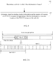
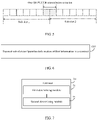
FIG. 1 is a flowchart of a resource determining method according to an embodiment of this disclosure; -
FIG. 2A is a first schematic diagram of a slot of a transmission location in example 1 of this disclosure; -
FIG. 2B is a second schematic diagram of a slot of a transmission location in example 1 of this disclosure; -
FIG. 2C is a third schematic diagram of a slot of a transmission location in example 1 of this disclosure; -
FIG. 3 is a schematic diagram of a slot of a transmission location in example 2 of this disclosure; -
FIG. 4 is a schematic diagram of a slot of a transmission location in example 3 of this disclosure; -
FIG. 5 is a schematic diagram of a slot of a transmission location in example 4 of this disclosure; -
FIG. 6 is a flowchart of a resource configuration method according to an embodiment of this disclosure; -
FIG. 7 is a first schematic structural diagram of a terminal according to an embodiment of this disclosure; -
FIG. 8 is a first schematic structural diagram of a network device according to an embodiment of this disclosure; -
FIG. 9 is a second schematic structural diagram of a terminal according to an embodiment of this disclosure; and -
FIG. 10 is a second schematic structural diagram of a network device according to an embodiment of this disclosure. - To describe the technical solutions in the embodiments of this disclosure more clearly, the following briefly describes the accompanying drawings required for describing the embodiments of this disclosure. Apparently, the accompanying drawings in the following descriptions show only some embodiments of this disclosure, and a person of ordinary skill in the art may still derive other drawings from these accompanying drawings without creative efforts.
- A wireless communication system in the embodiments of this disclosure includes a terminal and a network device. The terminal may also be referred to as a terminal device or user equipment (User Equipment, UE). The terminal may be a terminal side device such as a mobile phone, a tablet computer (Tablet Personal Computer), a laptop computer (Laptop Computer), a personal digital assistant (Personal Digital Assistant, PDA), a mobile Internet device (Mobile Internet Device, MID), a wearable device (Wearable Device), or an in-vehicle device. It should be noted that the specific type of the terminal is not limited in the embodiments of this disclosure. The network device may be a base station or a core network. The base station may be a 5G (5th Generation, 5G) base station or a base station of a later release (for example, a next generation node base station (next generation node base station, gNB), and a 5G new ratio (New Radio, NR) node base station (node base station, NB)), or base stations in other communications systems (for example, an evolved base station (evolved node base station, eNB), a wireless local area network (Wireless Local Area Network, WLAN) access point, or other access points). The base station may be referred to as a NodeB, an evolved NodeB, an access point, a base transceiver station (Base Transceiver Station, BTS), a radio base station, a radio transceiver, a basic service set (Basic Service Set, BSS), an extended service set (Extended Service Set, ESS), a NodeB, an evolved NodeB (eNB), a home NodeB, a home evolved NodeB, a WLAN access point, a wireless fidelity (Wireless Fidelity, WiFi) node, or other appropriate terms in the art. As long as a same technical effect is achieved, the base station is not limited to a specific technical term.
- In the embodiments of this disclosure, 1 frame equals 10 ms, 1 frame equals 10 subframes, and 1 subframe equals 2µ slots, where µ denotes a subcarrier spacing. Each slot may contain 14 orthogonal frequency division multiplexing (Orthogonal Frequency Division Multiplexing, OFDM) symbols (normal cyclic prefix (Cyclic Prefix, CP)), or contain 12 OFDM symbols (extended CP).
- As for PUCCH resource configuration and transmission, a PUCCH symbol length is configurable. Different PUCCH formats support different OFDM symbol lengths. Format 0 and
format 2 of PUCCH are short formats, whose corresponding number of symbols may be 1 or 2.Format 1, format 3, and format 4 of PUCCH are long formats, whose corresponding number of symbols may be 4 to 14. However, all PUCCH resources are usually configured in one slot, and PUCCH resources in time domain are configured by starting symbol and the number of symbols, where a starting symbol index is an offset in a number of symbols with respect to a starting location, that is, the first OFDM symbol, of the slot. The UE may determine a time domain resource location of the PUCCH based on the starting symbol and the number of symbols of the PUCCH. - In the embodiments of this disclosure, one slot (slot) may be divided into a plurality of sub-slots (sub-slot). The PUCCH can be transmitted in each of the sub-slots. In an embodiment, the number of symbols contained in each sub-slot may be configured by RRC, for example, configured by a parameter SubslotLength-ForPUCCH. For example, each sub-slot may contain 2 or 7 symbols.
- The embodiments of this disclosure are described in detail below with reference to the accompanying drawings.
- Referring to
FIG. 1, FIG. 1 is a flowchart of a resource determining method according to an embodiment of this disclosure. The method is applied to a terminal, and as shown inFIG. 1 , the method includes the following steps:
Step 101: Determine a sub-slot in which first information is located. - In this embodiment, the sub-slot in which first information is located may be expressed as a sub-slot in which a transmission resource of the first information is located, or a sub-slot for transmitting the first information.
- Optionally, the first information may be a scheduling request (Scheduling Request, SR) or CSI. The SR is a type of uplink control information (Uplink Control Information, UCI), mainly used for the terminal to request an uplink data transmission resource from a base station in a case that the terminal needs to transmit uplink data but no uplink data transmission resource is available. An SR transmission resource is configured by radio resource control (Radio Resource Control, RRC), and is periodical. For example, a periodicity of the SR may be 2 or 7 symbols (such as OFDM symbols), that is, shorter than 1 slot; or may be 1 or n (n is an integer greater than 1) slots. In a case that the periodicity of the SR is longer than 1 slot, when being configured by RRC, a slot offset in the periodicity of the SR may be configured by offsetting. However, a periodicity of the CSI is n slots, for example, with a minimum being 4 slots. When the CSI is being configured, a slot offset of the CSI in a period is configured. The base station configures one PUCCH resource for each SR or CSI.
- Step 102: Determine, based on starting symbol information and the number of symbols of a PUCCH resource corresponding to the first information, a resource location of the PUCCH resource in the sub-slot.
- It should be noted that in this embodiment, the terminal is configured with a sub-slot-based PUCCH resource, which means that the PUCCH resource is configured based on sub-slots. As for the CSI, the CSI is transmitted in each period. To be specific, the CSI is transmitted after a location of the PUCCH resource is determined (except for special cases, for example, when the CSI is dropped during UCI multiplexing or during handling of a collision with another channel). However, as for SR, only a SR transmission occasion in a PUCCH (a SR transmission occasion in a PUCCH) is determined. If the terminal needs to transmit SR, only a positive SR is transmitted in a PUCCH, and a negative SR is not transmitted in the PUCCH.
- Optionally, a starting symbol (starting symbol, for example, an OFDM symbol) of the PUCCH resource may be defined with respect to the first symbol of a corresponding slot (slot), or may be defined with respect to the first symbol of a corresponding sub-slot (sub-slot). The starting symbol information may be a starting symbol index (startingSymbolIndex), a starting symbol location, or the like.
- In an implementation, the starting symbol index of the PUCCH resource may be an offset, in a number of symbols, of a starting symbol (for example, an OFDM symbol) of the PUCCH resource with respect to the first symbol (for example, an OFDM symbol) of a slot in which the PUCCH resource is located.
- In another implementation, the starting symbol index of the PUCCH resource may be an offset, in a number of symbols, of a starting symbol (for example, an OFDM symbol) of the PUCCH resource with respect to the first symbol (for example, an OFDM symbol) of a sub-slot in which the PUCCH resource is located. It may be understood that the starting symbol index herein is less than a symbol length of the sub-slot.
- In the resource determining method in this embodiment of this disclosure, the sub-slot (sub-slot) in which the first information such as SR or CSI is located can be determined, and based on the starting symbol information and the number of symbols of the corresponding PUCCH resource, the resource location of a PUCCH resource in the sub-slot can be determined. Therefore, when the terminal is configured with a sub-slot-based PUCCH resource, a transmission location can be determined, improving effectiveness of a communications system.
- In this embodiment of this disclosure, before determining the sub-slot in which the first information is located, the terminal may receive configuration information of the first information from a network device so as to determine the sub-slot based on the configuration information. In a specific implementation, as for the first information, its slot may be determined before its sub-slot is determined, or its slot may be determined after its sub-slot is determined.
- Optionally, when the first information is CSI, or the first information is a SR and a periodicity (that is, a transmission periodicity) of the SR is longer than one slot, the process of determining a sub-slot in
step 101 may include: determining, based on configuration information of the first information, a slot in which the first information is located, where the configuration information indicates a periodicity and an offset of the first information, the periodicity measured in slots and the offset measured in slots; and determining the sub-slot in which the first information is located based on any one of the following: - (1) a pre-defined relationship between the sub-slot and the slot.
- Optionally, the pre-definition in (1) may be a definition by a protocol.
- In an implementation, the pre-defined relationship in (1) may include any one of the following:
- the sub-slot is the first sub-slot of the slot; and
- the sub-slot is the last sub-slot of the slot.
- In this way, based on the pre-definition, the first sub-slot or the last sub-slot may be defined, which can help the terminal determine the sub-slot desired, thereby improving transmission performance.
- It can be understood that in addition to the above-mentioned cases, the pre-defined relationship in (1) may alternatively have other cases, for example, it is pre-defined that the sub-slot is one with the longest symbol length of the slots. This is not limited in this embodiment.
- Optionally, the starting symbol information in (2) may be a starting symbol index.
- In an implementation, the starting symbol index may be an offset in a number of symbols with respect to the first symbol of a corresponding slot. As such, based on the starting symbol index and the number of symbols contained in the sub-slot, a sub-slot in which corresponding information is located can be determined. For example, if one slot contains 14 symbols, the slot is divided into two sub-slots each containing 7 symbols, and a starting symbol index of a PUCCH resource corresponding to the CSI is 2. Then the sub-slot in which the CSI is located is the first sub-slot.
- In an implementation, the starting symbol index may be an offset in a number of symbols with respect to the first symbol of a corresponding sub-slot. In this case, the corresponding sub-slot may be determined based on a preset rule according to, for example, a value obtained by using a remainder finding formula lomodN, where l 0 denotes the starting symbol index of the PUCCH resource, N denotes the number of sub-slots included in one slot, and mod denotes a remainder finding sign. The preset rule is, for example, a correspondence between values obtained by remainder finding and sub-slots, for example, 0 corresponds to the first sub-slot, and 1 corresponds to the second sub-slot.
- Optionally, the offset in (3) may be measured in sub-slots, or may be measured in symbols. The offset may be used for indicating an ordinal position of the sub-slot in the corresponding slot, that is, a sub-slot offset with respect to the first sub-slot of the slot; or, may be used for indicating a symbol offset of a starting symbol of the sub-slot with respect to a starting symbol of the corresponding slot.
- In an implementation, the terminal may receive sub-slot configuration information of the first information from the network device, where the sub-slot configuration information indicates an offset of the sub-slot in which the first information is located in the slot in which the first information is located.
- Further, the sub-slot configuration information may be transmitted by using a new RRC parameter. For example, as for CSI configuration, the new RRC parameter may be CSI-ReportSub-slotOffset INTERGER(0...N-1), where N denotes the number of sub-slots in one slot.
- It should be noted that in a case that the first information is CSI, or the first information is a SR and a periodicity (that is, a transmission periodicity) of the SR is longer than one slot, and the starting symbol index of the corresponding PUCCH resource is defined with respect to the first symbol of the slot in which the PUCCH resource is located, if the first information further includes hybrid automatic repeat request acknowledgement (Hybrid Automatic Repeat Request-ACK, HARQ-ACK) feedback information, a starting symbol of the PUCCH resource corresponding to the HARQ-ACK feedback information is defined with respect to the first symbol of a sub-slot in which the PUCCH resource is located. To be specific, the starting symbol index of the PUCCH resource may be an offset, in a number of symbols, of the starting symbol of the PUCCH resource with respect to the first symbol of the sub-slot in which the PUCCH resource is located.
- Optionally, in a case that the first information is a SR and a periodicity of the SR is one slot, a process of determining the sub-slot in the
Step 101 may include:
determining a sub-slot in which the SR is located in each slot based on any one of the following: - (1) a pre-defined relationship between the sub-slot and each slot.
- Optionally, the pre-definition in (1) may be a definition by a protocol.
- In an implementation, the pre-defined relationship in (1) may include any one of the following:
- the sub-slot is the first sub-slot of each slot; and
- the sub-slot is the last sub-slot of each slot.
- Such pre-definition which defines the sub-slot as the first sub-slot or the last sub-slot helps the terminal determine the sub-slot desired, thereby improving transmission performance.
- It can be understood that in addition to the above-mentioned cases, the pre-defined relationship in (1) may alternatively have other cases, for example, it is pre-defined that the sub-slot is one with the longest symbol length of the slots. This is not limited in this embodiment.
- Optionally, the starting symbol information in (2) may be a starting symbol index.
- In an implementation, the starting symbol index may be an offset in a number of symbols with respect to the first symbol of a corresponding slot or sub-slot. For a manner of determining the sub-slot, reference may be made to the foregoing description.
- Optionally, the offset in (3) may be measured in sub-slots, or may be measured in symbols. The offset may be used for indicating an ordinal position of the sub-slot in each slot, that is, a sub-slot offset with respect to the first sub-slot of the slot; or, may be used for indicating a symbol offset of a starting symbol of the sub-slot with respect to a starting symbol of the corresponding slot.
- In an implementation, the terminal may receive sub-slot configuration information of the first information from the network device, where the sub-slot configuration information indicates an offset of the sub-slot in which the first information is located in each slot.
- Further, the sub-slot configuration information may be transmitted by using a new RRC parameter. For example, as for SR configuration, the new RRC parameter may be SR-ReportSub-slotOffset INTERGER(0...N-1), where N denotes the number of sub-slots in one slot.
- Optionally, in a case that the first information is an SR and a periodicity of the SR is shorter than one slot (for example, 2 symbols or 7 symbols), the process of determining a sub-slot in
step 101 may include:
determining a sub-slot in which the SR is located in each slot based on any one of the following: - (1) the starting symbol information of the PUCCH resource.
- Optionally, the starting symbol information in (1) may be a starting symbol index.
- In an implementation, the starting symbol index may be an offset in a number of symbols with respect to the first symbol of a corresponding slot. In this case, the sub-slot in which the SR is located may be determined by performing the following process: first, a formula (l 0 mod N) mod SR PERIODICITY =0 is applied to determine a PUCCH transmission occasion resource in one slot, where the PUCCH transmission occasion resource may be provided in plurality, l 0 denotes the starting symbol index (for example, a starting symbol index of a PUCCH corresponding to a SR configured by RRC), l denotes a starting symbol index of a SR PUCCH transmission occasion resource (an offset in a number of symbols with respect to the first symbol of the slot), for example, its values being 0, 1, ..., 13, and SR PERIODICITY denotes the number of symbols in the periodicity of the SR; as for a value (for example, 2) of the starting symbol location l that satisfies the foregoing formula, a SR PUCCH transmission occasion resource location can be determined based on the starting symbol location l and the number of symbols of the PUCCH; then the sub-slot in which the SR is located is determined based on the SR PUCCH transmission occasion resource location and the sub-slot configuration. It should be noted that if one determined SR PUCCH transmission occasion resource is across a sub-slot boundary, with a starting symbol of the PUCCH in one sub-slot and an end symbol thereof in another sub-slot, then that PUCCH transmission occasion resource is unusable; or, when the PUCCH transmission occasion resource overlaps another channel (for example, HARQ-ACK PUCCH), the PUCCH transmission occasion resource may not cross a sub-slot boundary (a resource across a sub-slot boundary is unusable), and otherwise, the PUCCH transmission occasion resource may cross a sub-slot boundary (a resource across a sub-slot boundary is usable).
- In another implementation, the starting symbol index may be an offset in a number of symbols with respect to the first symbol of a corresponding sub-slot. In this case, if the periodicity of the SR is shorter than or equal to a symbol length of the sub-slot in which the SR is located, then there is a SR PUCCH transmission occasion in each sub-slot. The formula (l 0 mod N) mod SR PERIODICITY =0 may be used to determine a PUCCH transmission occasion resource in one sub-slot, where the PUCCH transmission occasion resource may be provided in plurality, l 0 denotes the starting symbol index (for example, a starting symbol index of a PUCCH corresponding to a SR configured by RRC), l denotes a starting symbol index of a SR PUCCH transmission occasion resource (an offset, in a number of symbols, with respect to the first symbol of the sub-slot), for example, its values being symbol locations in the sub-slot, such as 0, 1, ... (length of sub-slot - 1), and SR PERIODICITY denotes the number of symbols in the periodicity of the SR; as for a value (for example, 2) of the starting symbol location l that satisfies the foregoing formula, a SR PUCCH transmission occasion resource can be determined based on the starting symbol location l and the number of symbols of the PUCCH.
- (2) in a case that the periodicity of the SR (for example, 7 symbols) is longer than the symbol length of the sub-slot (for example, 2 symbols), a preconfigured offset of the sub-slot in the periodicity of the SR.
- Optionally, the offset in (2) may be measured in sub-slots, or may be measured in symbols. The offset may be used for indicating an ordinal position of the sub-slot in a corresponding periodicity of the SR, that is, a sub-slot offset with respect to the first sub-slot of the periodicity of the SR; or, may be used for indicating a symbol offset of a starting symbol of the sub-slot with respect to a starting symbol of the corresponding periodicity of the SR.
- In an implementation, the terminal may receive sub-slot configuration information of the first information from the network device, where the sub-slot configuration information indicates an offset of the sub-slot in which the SR is located in the periodicity of the SR when the periodicity of the SR is longer than the symbol length of the sub-slot in which the SR is located and shorter than one slot. In this case, the sub-slot in which the SR is located may be determined based on the offset and the periodicity of the SR.
- With reference to specific examples and accompanying drawings, the following describes the resource determining procedure in this disclosure.
- Example 1 takes CSI as an example, where a periodicity and offset configuration of the CSI (CSI-ReportPeriodicityAndOffset) is {slots 4, and INTEGER(0..3) = 1}, indicating that the CSI has a periodicity of 4 slots and an offset of 1 slot.
- If in a PUCCH configuration (PUCCH-Config) corresponding to a PUCCH resource that corresponds to the CSI, SubslotLength-ForPUCCH is configured as 7, which indicates that the number of symbols in a sub-slot is 7, a starting symbol index (startingSymbolIndex) of the PUCCH resource is configured as 2, and the number of symbols (nrofSymbols) is configured as 4, where the starting symbol index is an offset in a number of symbols with respect to the first symbol of a slot in which the PUCCH resource is located, then based on the foregoing configuration content, it can be determined that a slot in which the CSI is located is the second slot in the period (4 slots), a sub-slot in which the CSI is located is the first sub-slot of the second slot, and a resource location of the PUCCH resource that corresponds to the CSI in the first sub-slot is from the third symbol to the sixth symbol, as shown in
FIG. 2A . - If the starting symbol index of the PUCCH resource is configured as 8, the number of symbols is configured as 4, and other configuration remains unchanged, then based on the configuration content, it can be determined that the slot in which the CSI is located is the second slot of the period (4 slots), the sub-slot in which the CSI is located is the second sub-slot of the second slot, and a resource location of the PUCCH resource that corresponds to the CSI in the second sub-slot is from the third symbol to the sixth symbol, as shown in
FIG. 2B . - Likewise, if PUCCH-Config corresponding to a PUCCH resource for HARQ-ACK configures SubslotLength-ForPUCCH as 7, the starting symbol index of the corresponding PUCCH resource as 2, and the number of symbols as 4, then the starting symbol index is an offset in a number of symbols with respect to the first symbol of a sub-slot in which the PUCCH resource is located (less than length of the sub-slot). Then based on physical downlink shared channel (Physical Downlink Shared Channel, PDSCH) to- HARQ-ACK_feedback timing indicator, PDSCH-to-HARQ_feedback timing indicator, or an RRC parameter dl-DataToUL-ACK, a sub-slot of the HARQ-ACK feedback can be determined, where the sub-slot may be the second sub-slot of a corresponding slot, and a resource location of the PUCCH resource in the sub-slot may be determined based on a starting symbol and the number of symbols of the PUCCH, as shown in
FIG. 2C . - It should be noted that, under such configuration, in one implementation, a starting symbol index of a CSI PUCCH (or SR PUCCH) is with respect to a starting symbol of a corresponding slot, and the starting symbol index may be greater than or equal to the length of a sub-slot, but a base station should ensure that the CSI PUCCH (or SR PUCCH) is configured to be located in only one sub-slot. In another implementation, the starting symbol index of the CSI PUCCH (or SR PUCCH) corresponds to the starting symbol of the corresponding slot, the starting symbol index may be greater than or equal to the length of a sub-slot, and the base station may configure the CSI PUCCH (or SR PUCCH) to be located in different sub-slots,that is, to cross a sub-slot boundary. Alternatively, when the PUCCH resource does not collide with another channel (for example, HARQ-ACK PUCCH), the PUCCH may cross a sub-slot boundary, and otherwise, the PUCCH may not cross a sub-slot boundary.
- Example 2 takes CSI as an example, where a periodicity and offset configuration of the CSI (CSI-ReportPeriodicityAndOffset) is {slots4, and INTEGER(0..3) = 1}, indicating that the CSI has a periodicity of 4 slots and an offset of 1 slot.
- If in a PUCCH configuration (PUCCH-Config) corresponding to a PUCCH resource that corresponds to the CSI, SubslotLength-ForPUCCH is configured as 7, which means that the number of symbols in a sub-slot is 7, a starting symbol index (startingSymbolIndex) of the PUCCH resource is configured as 2, and the number of symbols (nrofSymbols) is configured as 4, where the starting symbol index is an offset in a number of symbols with respect to the first symbol of a sub-slot in which the PUCCH resource is located, and the starting symbol index must be less than a symbol length of the sub-slot (7), then based on the foregoing configuration content, it can be determined that a slot in which the CSI is located is the second slot in a period (4 slots), as shown in
FIG. 3 ; as for determining of the sub-slot, it may be determined as pre-defined, for example, that the desired sub-slot is the first sub-slot of the slot, that a sub-slot in which the CSI is located is the first sub-slot of the second slot, as shown inFIG. 3 . - Example 3 takes CSI as an example, where a periodicity and offset configuration of the CSI (CSI-ReportPeriodicityAndOffset) is {slots4, and INTEGER(0..3) = 1}, indicating that the CSI has a periodicity of 4 slots and an offset of 1 slot.
- In a PUCCH configuration (PUCCH-Config) corresponding to a PUCCH resource that corresponds to the CSI, SubslotLength-ForPUCCH is configured as 7, meaning the number of symbols in a sub-slot is 7, a starting symbol index (startingSymbolIndex) of the PUCCH resource is configured as 1, and the number of symbols (nrofSymbols) is configured as 4, where the starting symbol index is an offset in a number of symbols with respect to the first symbol of a sub-slot in which the PUCCH resource is located, and the starting symbol index must be less than a symbol length of the sub-slot (7). In addition, a sub-slot offset in the slot is configured by RRC, for example, RRC configuration information includes CSI-ReportSub-slotOffset INTERGER(0...N-1), where N denotes the number of sub-slots in one slot. For example, N = 2, and CSI-ReportSub-slotOffset = 1, which indicates the second sub-slot of the slot. Then based on the foregoing configuration content, it can be determined that the slot in which the CSI is located is the second slot in a period (4 slots), the sub-slot in which the CSI is located is the second sub-slot of the second slot, and a resource location of the PUCCH resource that corresponds to the CSI in the second sub-slot is from the second symbol to the fifth symbol, as shown in
FIG. 4 . - It should be noted that, the foregoing example 1 to example 3 are described by using CSI as an example. However, if the CSI is replaced with a SR (a periodicity of the SR is longer than or equal to one slot), the foregoing resource determining procedure is also applicable. Details are not described herein again.
- Example 4 takes a SR as an example, where a periodicity of the SR is shorter than 1 slot, for example, the periodicity is 2 symbols or 7 symbols. If a periodicity and offset configuration of the SR is based on slots, and a starting symbol index of a PUCCH resource corresponding to the SR is an offset in a number of symbols with respect to the first symbol of a slot in which the PUCCH resource is located, then a starting symbol location l of a PUCCH transmission occasion resource for the SR may be determined by using a formula (l 0 mod N) mod SR PERIODICITY =0 in related technology, where l 0 denotes the starting symbol index, and SR PERIODICITY denotes the number of symbols in the periodicity of the SR. In this case, for a plurality of SR PUCCH transmission occasion resources determined in a slot, none of the SR PUCCH transmission occasion resources may cross a sub-slot boundary. If a PUCCH transmission occasion resource is across a sub-slot boundary (as shown in
FIG. 5 ), that resource is unusable. - Referring to
FIG. 6, FIG. 6 is a flowchart of a resource configuration method according to an embodiment of this disclosure. The method is applied to a network device, and as shown inFIG. 6 , the method includes the following steps. - Step 601: Transmit sub-slot configuration information of first information to a terminal.
- The sub-slot configuration information indicates an offset of a sub-slot in which the first information is located in a slot in which the first information is located.
- Alternatively, in a case that a periodicity of the first information is longer than a symbol length of the sub-slot in which the first information is located and shorter than one slot, the sub-slot configuration information indicates an offset of the sub-slot in which the first information is located in the periodicity of the first information.
- Optionally, the sub-slot configuration information is transmitted by using a new RRC parameter.
- In an implementation, the new RRC parameter may be CSI-ReportSub-slotOffset INTERGER(0...N-1) or SR-ReportSub-slotOffset INTERGER(0...N-1), where N denotes the number of sub-slots in one slot. For example, if N = 2 and CSI-ReportSub-slotOffset = 1, the second sub-slot of the slot is indicated.
- Optionally, the offset is measured in sub-slots, or the offset is measured in symbols.
- Optionally, the first information includes one of the following: a SR and CSI.
- In this way, with the sub-slot configuration information transmitted to the terminal, the terminal can determine transmission information such as a sub-slot in which the SR or CSI is located.
- The foregoing embodiments describe the resource determining method and the resource configuration method in this disclosure. The following describes the terminal and network device in this disclosure with reference to the embodiments and the accompanying drawings.
- Referring to
FIG. 7, FIG. 7 is a schematic structural diagram of a terminal according to an embodiment of this disclosure. As shown inFIG. 7 , the terminal 70 includes: - a first determining
module 71, configured to determine a sub-slot in which first information is located; and - a second determining
module 72, configured to determine, based on starting symbol information and the number of symbols of a PUCCH resource corresponding to the first information, a resource location of the PUCCH resource in the sub-slot. - Optionally, the first determining
module 71 includes: - a first determining unit, configured to determine, based on configuration information of the first information, a slot in which the first information is located, where the configuration information indicates a periodicity and an offset of the first information, the periodicity measured in slots and the offset measured in slots; and
- a second determining unit, configured to determine the sub-slot in which the first information is located based on any one of the following:
- a pre-defined relationship between the sub-slot and the slot;
- the starting symbol information of the PUCCH resource; and
- a preconfigured offset of the sub-slot in the slot.
- Optionally, the pre-defined relationship between the sub-slot and the slot includes one of the following:
- the sub-slot is the first sub-slot of the slot; and
- the sub-slot is the last sub-slot of the slot.
- Optionally, the starting symbol information of the PUCCH resource includes: a starting symbol index of the PUCCH resource.
- Optionally, the starting symbol index of the PUCCH resource is an offset, in a number of symbols, of a starting symbol of the PUCCH resource with respect to the first symbol of a slot in which the PUCCH resource is located; or
the starting symbol index of the PUCCH resource is an offset, in a number of symbols, of the starting symbol of the PUCCH resource with respect to the first symbol of a sub-slot in which the PUCCH resource is located. - Optionally, the first information includes one of the following:
- a scheduling request SR and channel state information CSI, where
- in a case that the first information is a SR, a periodicity of the SR is longer than one slot.
- Further, when the first information also includes HARQ-ACK feedback information, a starting symbol of the PUCCH resource corresponding to the HARQ-ACK feedback information is defined with respect to the first symbol of a sub-slot in which the PUCCH resource is located.
- Optionally, in a case that the first information is a SR and a periodicity of the SR is one slot, the first determining
module 71 is specifically configured to:
determine a sub-slot in which the SR is located in each slot based on any one of the following: - a pre-defined relationship between the sub-slot and each slot;
- the starting symbol information of the PUCCH resource; and
- a preconfigured offset of the sub-slot in each slot.
- Optionally, in a case that the first information is a SR and a periodicity of the SR is shorter than one slot, the first determining
module 71 is specifically configured to:
determine a sub-slot in which the SR is located in each slot based on any one of the following: - the starting symbol information of the PUCCH resource; and
- in a case that the periodicity of the SR is longer than a symbol length of the sub-slot, a preconfigured offset of the sub-slot in the periodicity of the SR.
- The terminal 70 in this embodiment of this disclosure can implement the processes of the method embodiment in
FIG. 1 , with the same beneficial effects achieved. To avoid repetition, details are not described herein again. - Referring to
FIG. 7, FIG. 7 is a schematic structural diagram of a network device according to an embodiment of this disclosure. As shown inFIG. 8 , thenetwork device 80 includes: - a transmitting
module 81, configured to transmit sub-slot configuration information of first information to a terminal, where - the sub-slot configuration information indicates an offset of a sub-slot in which the first information is located in a slot in which the first information is located; or
- in a case that a periodicity of the first information is longer than a symbol length of the sub-slot in which the first information is located and shorter than one slot, the sub-slot configuration information indicates an offset of the sub-slot in which the first information is located in the periodicity of the first information.
- Optionally, the sub-slot configuration information is transmitted by using a new RRC parameter.
- In an implementation, the new RRC parameter may be CSI-ReportSub-slotOffset INTERGER(0...N-1) or SR-ReportSub-slotOffset INTERGER(0...N-1), where N denotes the number of sub-slots in one slot. For example, if N = 2 and CSI-ReportSub-slotOffset = 1, the second sub-slot of the slot is indicated.
- Optionally, the offset is measured in sub-slots, or the offset is measured in symbols.
- Optionally, the first information includes one of the following: a SR and CSI.
- In this way, with the sub-slot configuration information transmitted to the terminal, the terminal can determine transmission information such as a sub-slot in which the SR or CSI is located.
- An embodiment of this disclosure further provides a communications device, including a processor, a memory, and a computer program stored in the memory and capable of running on the processor. When the computer program is executed by the processor, the processes of the embodiments of the foregoing method shown in
FIG. 1 are implemented, or the processes of the embodiments of the foregoing method shown inFIG. 6 are implemented, with the same technical effects achieved. To avoid repetition, details are not described herein again. The communications device is optionally a terminal or a network device. - Referring to
FIG. 9, FIG. 9 is a schematic diagram of a hardware structure of a terminal for implementing the embodiments of this disclosure. The terminal 900 includes but is not limited to components such as aradio frequency unit 901, anetwork module 902, anaudio output unit 903, aninput unit 904, asensor 905, adisplay unit 906, auser input unit 907, aninterface unit 908, amemory 909, aprocessor 910, and apower supply 911. A person skilled in the art may understand that the structure of the terminal shown inFIG. 9 does not constitute any limitation on the terminal. The terminal may include more or fewer components than those shown in the figure, or combine some of the components, or arrange the components differently. In this embodiment of this disclosure, the terminal includes but is not limited to a mobile phone, a tablet computer, a notebook computer, a palmtop computer, an in-vehicle terminal, a wearable device, a pedometer, or the like. - The
processor 910 is configured to determine, a sub-slot in which first information is located; and based on starting symbol information and the number of symbols of a PUCCH resource corresponding to the first information, a resource location of the PUCCH resource in the sub-slot. The first information may be SR or CSI. - The terminal 900 in this embodiment of this disclosure can implement the processes of the method embodiment in
FIG. 1 , with the same beneficial effects achieved. To avoid repetition, details are not described herein again. - It should be understood that, in this embodiment of this disclosure, the
radio frequency unit 901 may be configured to transmit or receive a signal in an information transmitting/receiving or call process. Specifically, theradio frequency unit 901 receives downlink data from a base station and transmits the downlink data to theprocessor 910 for processing; and transmits uplink data to the base station. Generally, theradio frequency unit 901 includes but is not limited to an antenna, at least one amplifier, a transceiver, a coupler, a low noise amplifier, a duplexer, and the like. In addition, theradio frequency unit 901 may also communicate with a network and other devices via a wireless communications system. - The terminal provides a user with wireless broadband Internet access by using the
network module 902, for example, helping the user to transmit and receive e-mails, browse web pages, and access streaming media. - The
audio output unit 903 may convert audio data into an audio signal, and output the audio signal as sound, where the audio data is received by theradio frequency unit 901 or thenetwork module 902, or stored in thememory 909. In addition, theaudio output unit 903 may further provide audio output (for example, a call signal received tone or a message received tone) that is related to a specific function performed by theterminal 900. Theaudio output unit 903 includes a speaker, a buzzer, a receiver, and the like. - The
input unit 904 is configured to receive an audio or video signal. Theinput unit 904 may include a graphics processing unit (Graphics Processing Unit, GPU) 9041 and a microphone 9042. Thegraphics processing unit 9041 processes image data of a static picture or a video that is obtained by an image capture apparatus (for example, a camera) in a video capture mode or an image capture mode. A processed image frame may be displayed on thedisplay unit 906. The image frame processed by thegraphics processing unit 9041 may be stored in the memory 909 (or another storage medium) or transmitted by using theradio frequency unit 901 or thenetwork module 902. The microphone 9042 is capable of receiving sounds and processing such sounds into audio data. The processed audio data may be converted in a telephone call mode into a format that can be transmitted by theradio frequency unit 901 to a mobile communications base station, for outputting. - The terminal 900 further includes at least one
sensor 905, for example, an optical sensor, a motion sensor, and other sensors. Specifically, the optical sensor may include an ambient light sensor and a proximity sensor. The ambient light sensor may adjust luminance of thedisplay panel 9061 based on brightness of ambient light, and the proximity sensor may turn off adisplay panel 9061 and/or backlight when the terminal 900 moves close to an ear. As a type of motion sensor, an accelerometer sensor can detect magnitudes of accelerations in all directions (usually three axes), can detect a magnitude and a direction of gravity when being static, and can be applied to terminal posture recognition (such as screen switching between portrait and landscape, related games, and magnetometer posture calibration), functions related to vibration recognition (such as pedometer and tapping), and the like. Thesensor 905 may also include a fingerprint sensor, a pressure sensor, an iris sensor, a molecular sensor, a gyroscope, a barometer, a hygrometer, a thermometer, an infrared sensor, and the like. Details are not described herein. - The
display unit 906 is configured to display information input by the user or information provided for the user. Thedisplay unit 906 may include thedisplay panel 9061. Thedisplay panel 9061 may be configured in a form of a liquid crystal display (Liquid Crystal Display, LCD), an organic light-emitting diode (Organic Light-Emitting Diode, OLED), or the like. - The
user input unit 907 may be configured to receive input digit or character information, and generate key signal input that is related to user setting and function control of the terminal. Specifically, theuser input unit 907 includes atouch panel 9071 andother input devices 9072. Thetouch panel 9071 is also referred to as a touchscreen, and may collect a touch operation of the user on or near the touch panel (for example, an operation performed on or near thetouch panel 9071 by the user by using any appropriate object or accessory such as a finger or a stylus). Thetouch panel 9071 may include two parts: a touch detection apparatus and a touch controller. The touch detection apparatus detects a touch direction of a user, detects a signal brought by a touch operation, and transmits the signal to the touch controller. The touch controller receives touch information from the touch detection apparatus, converts the touch information into touchpoint coordinates, transmits the touchpoint coordinates to theprocessor 910, and receives and executes a command transmitted by theprocessor 910. In addition, thetouch panel 9071 may be implemented in a plurality of forms, for example, as a resistive, capacitive, infrared, or surface acoustic wave touch panel. In addition to thetouch panel 9071, theuser input unit 907 may further includeother input devices 9072. Specifically, theother input devices 9072 may include but are not limited to a physical keyboard, a function key (for example, a volume control key or a power on/off key), a trackball, a mouse, and a joystick. Details are not described herein. - Further, the
touch panel 9071 may cover thedisplay panel 9061. When detecting a touch operation on or near thetouch panel 9071, thetouch panel 9071 transmits the touch operation to theprocessor 910 for determining a type of the touch event. Then, theprocessor 910 provides a corresponding visual output on thedisplay panel 9061 based on the type of the touch event. Although inFIG. 9 , thetouch panel 9071 and thedisplay panel 9061 act as two separate parts to implement input and output functions of the terminal, in some embodiments, thetouch panel 9071 and thedisplay panel 9061 may be integrated to implement the input and output functions of the terminal. This is not specifically limited herein. - The
interface unit 908 is an interface for connecting an external apparatus to the terminal 900. For example, the external apparatus may include a wired or wireless headphone port, an external power supply (or battery charger) port, a wired or wireless data port, a memory card port, a port for connecting an apparatus provided with an identification module, an audio input/output (Input/Output, I/O) port, a video I/O port, or an earphone port. Theinterface unit 908 may be configured to receive input (for example, data information and electric power) from the external apparatus, and transmit the received input to one or more elements in the terminal 900; or may be configured to transmit data between the terminal 900 and the external apparatus. - The
memory 909 may be configured to store software programs and various data. Thememory 909 may mainly include a program storage area and a data storage area. The program storage area may store an operating system, an application program required by at least one function (for example, an audio playing function and an image playing function), and the like. The data storage area may store data (for example, audio data and an address book) created according to use of the mobile phone. In addition, thememory 909 may include a high-speed random access memory, and may further include a nonvolatile memory, for example, at least one disk storage device, a flash memory device, or another volatile solid-state storage device. - The
processor 910 is a control center of the terminal, which is connected to all components of the terminal by using various interfaces and lines. By running or executing software programs and/or modules stored in thememory 909 and invoking data stored in thememory 909, theprocessor 910 executes various functions of the terminal and processes data, so as to perform overall monitoring on the terminal. Theprocessor 910 may include one or more processing units. Optionally, theprocessor 910 may integrate an application processor and a modem processor. The application processor mainly processes an operating system, a user interface, an application program, and the like. The modem processor mainly processes wireless communication. It can be understood that the modem processor may alternatively not be integrated in theprocessor 910. - The terminal 900 may further include a power supply 911 (for example, a battery) that supplies power to the components. Optionally, the
power supply 911 may be logically connected to theprocessor 910 through a power management system, so as to implement functions such as charging management, discharging management, and power consumption management through the power management system. - In addition, the terminal 900 may further include some functional modules that are not shown. Details are not described herein.
- Referring to
FIG. 10, FIG. 10 is a schematic diagram of a hardware structure of a network device for implementing the embodiments of this disclosure. Thenetwork device 100 includes but is not limited to abus 101, atransceiver 102, anantenna 103, abus interface 104, aprocessor 105, and amemory 106. - In this embodiment of this disclosure, the
network device 100 further includes a computer program stored in thememory 106 and capable of running on theprocessor 105, where when the computer program is executed by theprocessor 105, the following step is implemented: - transmit sub-slot configuration information of first information to a terminal, where
- the sub-slot configuration information indicates an offset of a sub-slot in which the first information is located in a slot in which the first information is located; or
- in a case that a periodicity of the first information is longer than a symbol length of the sub-slot in which the first information is located and shorter than one slot, the sub-slot configuration information indicates an offset of the sub-slot in which the first information is located in the periodicity of the first information.
- Optionally, the first information includes one of the following: a SR and CSI.
- The
transceiver 102 is configured to transmit and receive data under control of theprocessor 105. - The
network device 100 in this embodiment of this disclosure can implement the processes of the method embodiment inFIG. 6 , with the same beneficial effects achieved. To avoid repetition, details are not described herein again. - In
FIG. 10 , in a bus architecture (represented by the bus 101), thebus 101 may include any quantity of interconnected buses and bridges, and thebus 101 connects various circuits that include one or more processors represented by theprocessor 105 and a memory represented by thememory 106. Thebus 101 may further connect various other circuits, such as a peripheral device, a voltage regulator, and a power management circuit. These are common sense in the art, and therefore are not further described in this specification. Thebus interface 104 provides an interface between thebus 101 and thetransceiver 102. Thetransceiver 102 may be one element, or may be a plurality of elements, for example, a plurality of receivers and transmitters, and provides a unit for communicating with various other apparatuses on a transmission medium. Data processed by theprocessor 105 is transmitted on a wireless medium through theantenna 103. Further, theantenna 103 receives data and transmits the data to theprocessor 105. - The
processor 105 is responsible for managing thebus 101 and general processing, and may further provide various functions, including timing, a peripheral interface, voltage regulation, power management, and other control functions. Thememory 106 may be configured to store data for use by theprocessor 105 when theprocessor 105 performs an operation. - Optionally, the
processor 105 may be a central processing unit (Central Processing Unit, CPU), an application-specific integrated circuit (Application Specific Integrated Circuit, ASIC), a field-programmable gate array (Field-Programmable Gate Array, FPGA), or a complex programmable logic device (Complex Programmable Logic Device, CPLD). - An embodiment of this disclosure further provides a computer-readable storage medium, where the computer-readable storage medium stores a computer program, and when the computer program is executed by a processor, the processes of the embodiments of the method shown in
FIG. 1 are implemented, or the processes of the embodiments of the method shown inFIG. 6 are implemented, and the same technical effects can be achieved. Therefore, details are not described herein again to avoid repetition. The computer-readable storage medium may be a read-only memory (Read-Only Memory, ROM), a random access memory (Random Access Memory, RAM), a magnetic disk, an optical disc, or the like. - It should be noted that, in this specification, the terms "include" and "comprise", or any of their variants are intended to cover a non-exclusive inclusion, such that a process, method, article, or apparatus that includes a list of elements not only includes those elements but also includes other elements that are not expressly listed, or further includes elements inherent to such process, method, article, or apparatus. Without more constraints, an element preceded by "includes a..." does not preclude the presence of other identical elements in the process, method, article, or apparatus that includes the element.
- In the embodiments provided in this application, it should be understood that the disclosed apparatus and method may be implemented in other manners. For example, the described apparatus embodiment is merely an example. For example, the unit division is merely logical function division and may be other division in actual implementation. For example, a plurality of units or components may be combined or integrated into another system, or some features may be ignored or may not be performed. In addition, the displayed or discussed mutual couplings or direct couplings or communication connections may be indirect couplings or communication connections through some interfaces, apparatuses or units, and may be implemented in electrical, mechanical, or other forms.
- The units described as separate parts may or may not be physically separate, and parts displayed as units may or may not be physical units, may be located in one position, or may be distributed on a plurality of network elements. Some or all of the units may be selected based on actual requirements to achieve the objectives of the solutions of the embodiments.
- In addition, functional units in the embodiments of this disclosure may be integrated into one processing unit, or each of the units may exist alone physically, or two or more units are integrated into one unit.
- According to the description of the foregoing implementations, persons skilled in the art can clearly understand that the method in the foregoing embodiments may be implemented by software in addition to a necessary universal hardware platform or by hardware only. In many cases, the former is a preferred implementation. Based on such an understanding, the technical solutions of this disclosure essentially or a part thereof that contributes to related technologies may be embodied in a form of a software product. The computer software product is stored in a storage medium (for example, a ROM/RAM, a magnetic disk, or an optical disc), and includes several instructions for instructing a terminal (which may be a mobile phone, a computer, a server, an air conditioner, a network device, or the like) to perform the methods described in the embodiments of this disclosure.
- It may be understood that the embodiments described in the embodiments of this disclosure may be implemented by hardware, software, firmware, middleware, microcode, or a combination thereof. In implementation by hardware, modules, units, and subunits may be implemented in one or more application-specific integrated circuits (Application Specific Integrated Circuits, ASIC), digital signal processors (Digital Signal Processor, DSP), digital signal processing devices (DSP Device, DSPD), programmable logic devices (Programmable Logic Device, PLD), field-programmable gate arrays (Field-Programmable Gate Array, FPGA), general-purpose processors, controllers, microcontrollers, microprocessors, other electronic units used to implement the functions described in this disclosure, or a combination thereof.
- For software implementation, the technologies described in the embodiments of this disclosure may be implemented by modules (for example, processes or functions) that perform the functions described in the embodiments of this disclosure. Software code may be stored in the memory and executed by the processor. The memory may be implemented in the processor or external to the processor.
- The foregoing describes the embodiments of this disclosure with reference to the accompanying drawings. However, this disclosure is not limited to the foregoing specific implementations. The foregoing specific implementations are merely illustrative rather than restrictive. In light of this disclosure, a person of ordinary skill in the art may develop many other forms without departing from the principle of this disclosure and the protection scope of the claims, and all such forms shall fall within the protection scope of this disclosure.
Claims (31)
- A resource determining method, applied to a terminal and comprising:determining a sub-slot in which first information is located; anddetermining, based on starting symbol information and the number of symbols of a physical uplink control channel PUCCH resource corresponding to the first information, a resource location of the PUCCH resource in the sub-slot.
- The method according to claim 1, wherein the determining a sub-slot in which first information is located comprises:determining, based on configuration information of the first information, a slot in which the first information is located, wherein the configuration information indicates a periodicity and an offset of the first information, the periodicity measured in slots and the offset measured in slots; anddetermining the sub-slot in which the first information is located based on any one of the following:a pre-defined relationship between the sub-slot and the slot;the starting symbol information of the PUCCH resource; anda preconfigured offset of the sub-slot in the slot.
- The method according to claim 2, wherein the pre-defined relationship between the sub-slot and the slot comprises any one of the following:the sub-slot is the first sub-slot of the slot; andthe sub-slot is the last sub-slot of the slot.
- The method according to claim 1 or 2, wherein the starting symbol information of the PUCCH resource comprises: a starting symbol index of the PUCCH resource.
- The method according to claim 4, whereinthe starting symbol index of the PUCCH resource is an offset, in a number of symbols, of a starting symbol of the PUCCH resource with respect to the first symbol of a slot in which the PUCCH resource is located;
orthe starting symbol index of the PUCCH resource is an offset, in a number of symbols, of the starting symbol of the PUCCH resource with respect to the first symbol of a sub-slot in which the PUCCH resource is located. - The method according to any one of claims 1 to 5, wherein the first information comprises any one of the following:a scheduling request SR and channel state information CSI, whereinin a case that the first information is a SR, a periodicity of the SR is longer than one slot.
- The method according to any one of claims 1 to 6, wherein the PUCCH resource corresponding to the first information is located in only one sub-slot.
- The method according to claim 1, wherein in a case that the first information is a SR and a periodicity of the SR is one slot, the determining a sub-slot in which first information is located comprises:
determining a sub-slot in which the SR is located in each slot based on any one of the following:a pre-defined relationship between the sub-slot and each slot;the starting symbol information of the PUCCH resource; anda preconfigured offset of the sub-slot in each slot. - The method according to claim 1, wherein in a case that the first information is a SR and a periodicity of the SR is shorter than one slot, the determining a sub-slot in which first information is located comprises:
determining a sub-slot in which the SR is located in each slot based on any one of the following:the starting symbol information of the PUCCH resource; andin a case that the periodicity of the SR is longer than a symbol length of the sub-slot, a preconfigured offset of the sub-slot in the periodicity of the SR. - The method according to claim 6, wherein when the first information further comprises hybrid automatic repeat request acknowledgement HARQ-ACK feedback information,
a starting symbol index of a PUCCH resource corresponding to the HARQ-ACK feedback information is an offset, in a number of symbols, of the starting symbol of the PUCCH resource with respect to the first symbol of the sub-slot in which the PUCCH resource is located. - A resource configuration method, applied to a network device and comprising:transmitting configuration information of first information and sub-slot configuration information thereof to a terminal, wherein the configuration information indicates a periodicity and an offset of the first information, the periodicity measured in slots and the offset measured in slots, and the sub-slot configuration information indicates the number of symbols in a sub-slot, whereina PUCCH resource corresponding to the first information is located in only one sub-slot.
- The method according to claim 11, wherein the number of symbols in a sub-slot is 2 or 7.
- The method according to claim 11, wherein the sub-slot configuration information is transmitted by using a radio resource control RRC parameter.
- The method according to any one of claims 11 to 13, wherein the first information comprises any one of the following: a scheduling request SR and channel state information CSI.
- A resource configuration method, applied to a network device and comprising:transmitting sub-slot configuration information of first information to a terminal, whereinthe sub-slot configuration information indicates an offset of a sub-slot in which the first information is located in a slot in which the first information is located; orin a case that a periodicity of the first information is longer than a symbol length of the sub-slot in which the first information is located and shorter than one slot, the sub-slot configuration information indicates an offset of the sub-slot in which the first information is located in the periodicity of the first information.
- The method according to claim 15, wherein the sub-slot configuration information is transmitted by using a new radio resource control RRC parameter.
- The method according to claim 15, wherein the offset is measured in sub-slots, or the offset is measured in symbols.
- The method according to any one of claims 15 to 17, wherein the first information comprises any one of the following: a scheduling request SR and channel state information CSI.
- A terminal, comprising:a first determining module, configured to determine a sub-slot in which first information is located; anda second determining module, configured to determine, based on starting symbol information and the number of symbols of a physical uplink control channel PUCCH resource corresponding to the first information, a resource location of the PUCCH resource in the sub-slot.
- The terminal according to claim 19, wherein the first determining module comprises:a first determining unit, configured to determine, based on configuration information of the first information, a slot in which the first information is located, wherein the configuration information indicates a periodicity and an offset of the first information, the periodicity measured in slots and the offset measured in slots; anda second determining unit, configured to determine the sub-slot in which the first information is located based on any one of the following:a pre-defined relationship between the sub-slot and the slot;the starting symbol information of the PUCCH resource; anda preconfigured offset of the sub-slot in the slot.
- The terminal according to claim 19 or 20, wherein the starting symbol information of the PUCCH resource comprises: a starting symbol index of the PUCCH resource.
- The terminal according to claim 21, whereinthe starting symbol index of the PUCCH resource is an offset, in a number of symbols, of a starting symbol of the PUCCH resource with respect to the first symbol of a slot in which the PUCCH resource is located;
orthe starting symbol index of the PUCCH resource is an offset, in a number of symbols, of the starting symbol of the PUCCH resource with respect to the first symbol of a sub-slot in which the PUCCH resource is located. - The terminal according to any one of claims 19 to 22, wherein the first information comprises any one of the following:a scheduling request SR and channel state information CSI, whereinin a case that the first information is a SR, a periodicity of the SR is longer than one slot.
- The terminal according to any one of claims 19 to 23, wherein the PUCCH resource corresponding to the first information is located in only one sub-slot.
- A network device, comprising:a transmitting module, configured to transmit configuration information of first information and sub-slot configuration information thereof to a terminal, wherein the configuration information indicates a periodicity and an offset of the first information, the periodicity measured in slots and the offset measured in slots, and the sub-slot configuration information indicates the number of symbols in a sub-slot, whereina PUCCH resource corresponding to the first information is located in only one sub-slot.
- The network device according to claim 25, wherein the number of symbols in a sub-slot is 2 or 7.
- The network device according to claim 25, wherein the sub-slot configuration information is transmitted by using a radio resource control RRC parameter.
- The network device according to any one of claims 25 to 27, wherein the first information comprises any one of the following: a scheduling request SR and channel state information CSI.
- A network device, comprising:a transmitting module, configured to transmit sub-slot configuration information of first information to a terminal, whereinthe sub-slot configuration information indicates an offset of a sub-slot in which the first information is located in a slot in which the first information is located; orin a case that a periodicity of the first information is longer than a symbol length of the sub-slot in which the first information is located and shorter than one slot, the sub-slot configuration information indicates an offset of the sub-slot in which the first information is located in the periodicity of the first information.
- A communications device, comprising a memory, a processor, and a computer program stored in the memory and capable of running on the processor, wherein when the computer program is executed by the processor, the steps of the resource determining method according to any one of claims 1 to 10 are implemented, or the steps of the resource configuration method according to any one of claims 11 to 14 are implemented, or the steps of the resource configuration method according to any one of claims 15 to 18 are implemented.
- A computer-readable storage medium, storing a computer program, wherein when the computer program is executed by a processor, the steps of the resource determining method according to any one of claims 1 to 10 are implemented, or the steps of the resource configuration method according to any one of claims 11 to 14 are implemented, or the steps of the resource configuration method according to any one of claims 15 to 18 are implemented.
Applications Claiming Priority (2)
| Application Number | Priority Date | Filing Date | Title |
|---|---|---|---|
| CN201911114661.6A CN112804754B (en) | 2019-11-14 | 2019-11-14 | Resource determination method, resource configuration method, terminal and network equipment |
| PCT/CN2020/128096 WO2021093767A1 (en) | 2019-11-14 | 2020-11-11 | Resource determination method, resource configuration method, terminal, and network device |
Publications (3)
| Publication Number | Publication Date |
|---|---|
| EP4061083A1 true EP4061083A1 (en) | 2022-09-21 |
| EP4061083A4 EP4061083A4 (en) | 2022-12-14 |
| EP4061083B1 EP4061083B1 (en) | 2025-12-24 |
Family
ID=75803777
Family Applications (1)
| Application Number | Title | Priority Date | Filing Date |
|---|---|---|---|
| EP20886851.3A Active EP4061083B1 (en) | 2019-11-14 | 2020-11-11 | Resource determination method, resource configuration method, terminal, and network device |
Country Status (9)
| Country | Link |
|---|---|
| US (1) | US12232106B2 (en) |
| EP (1) | EP4061083B1 (en) |
| JP (1) | JP7379698B2 (en) |
| KR (2) | KR20250093591A (en) |
| CN (1) | CN112804754B (en) |
| BR (1) | BR112022009268A2 (en) |
| ES (1) | ES3060126T3 (en) |
| PT (1) | PT4061083T (en) |
| WO (1) | WO2021093767A1 (en) |
Families Citing this family (3)
| Publication number | Priority date | Publication date | Assignee | Title |
|---|---|---|---|---|
| CN112583546B (en) | 2019-09-27 | 2022-07-19 | 维沃移动通信有限公司 | Resource allocation method, device, equipment and storage medium |
| CN117812712A (en) * | 2022-09-30 | 2024-04-02 | 华为技术有限公司 | A communication method and device |
| CN115664610B (en) * | 2022-10-10 | 2024-07-12 | 杭州红岭通信息科技有限公司 | PUCCH (physical uplink control channel) sending method and terminal |
Family Cites Families (14)
| Publication number | Priority date | Publication date | Assignee | Title |
|---|---|---|---|---|
| ES2927975T3 (en) * | 2017-03-23 | 2022-11-14 | Sharp Kk | Downlink control channel for ultra-reliable, low-latency uplink communications |
| US10448414B2 (en) | 2017-03-23 | 2019-10-15 | Sharp Kabushiki Kaisha | Downlink control channel for uplink ultra-reliable and low-latency communications |
| EP3471489B1 (en) * | 2017-05-03 | 2023-03-29 | LG Electronics Inc. | Method for transmitting and receiving scheduling request between terminal and base station in wireless communication system and device for supporting same |
| KR102459279B1 (en) * | 2017-05-05 | 2022-10-26 | 엘지전자 주식회사 | Power headroom reporting method and apparatus therefor in wireless communication system |
| US20180368173A1 (en) * | 2017-06-15 | 2018-12-20 | Sharp Laboratories Of America, Inc. | Systems and methods for an enhanced scheduling request for 5g nr |
| RU2728525C1 (en) * | 2017-06-16 | 2020-07-30 | Телефонактиеболагет Лм Эрикссон (Пабл) | System and methods of configuring user equipment with pucch overlapping resources for transmitting scheduling requests |
| US20190045529A1 (en) | 2017-09-11 | 2019-02-07 | Intel IP Corporation | Scheduling request transmission opportunity and resource configuration in new radio |
| CN109660324B (en) | 2017-10-11 | 2021-01-08 | 维沃移动通信有限公司 | Demodulation reference signal transmission method, network equipment and terminal |
| KR102032526B1 (en) | 2017-11-10 | 2019-10-16 | 엘지전자 주식회사 | Method and apparatus for transceiving pucch carrying sr in a wireless communication system |
| CN113260077B (en) | 2017-11-15 | 2022-08-23 | 华为技术有限公司 | Random access method, user equipment and network equipment |
| WO2019139534A1 (en) * | 2018-01-12 | 2019-07-18 | Telefonaktiebolaget Lm Ericsson (Publ) | Configuration of periodic signals in a time division duplex communication system |
| CN110138529B (en) * | 2018-02-09 | 2021-11-23 | 维沃移动通信有限公司 | SR configuration method, network side equipment and terminal side equipment |
| US10980049B2 (en) | 2018-05-10 | 2021-04-13 | Qualcomm Incorporated | Allocating physical uplink control channel (PUCCH) resources for ultra-reliable low latency communication (URLLC) |
| WO2020056758A1 (en) * | 2018-09-21 | 2020-03-26 | Qualcomm Incorporated | Physical uplink control channel scheduling for ack-nack feedback in multi-transmission/reception point non-coherent joint transmissions |
-
2019
- 2019-11-14 CN CN201911114661.6A patent/CN112804754B/en active Active
-
2020
- 2020-11-11 PT PT208868513T patent/PT4061083T/en unknown
- 2020-11-11 KR KR1020257020238A patent/KR20250093591A/en active Pending
- 2020-11-11 EP EP20886851.3A patent/EP4061083B1/en active Active
- 2020-11-11 JP JP2022527866A patent/JP7379698B2/en active Active
- 2020-11-11 ES ES20886851T patent/ES3060126T3/en active Active
- 2020-11-11 KR KR1020227016701A patent/KR20220084150A/en not_active Ceased
- 2020-11-11 WO PCT/CN2020/128096 patent/WO2021093767A1/en not_active Ceased
- 2020-11-11 BR BR112022009268A patent/BR112022009268A2/en unknown
-
2022
- 2022-04-29 US US17/733,573 patent/US12232106B2/en active Active
Also Published As
| Publication number | Publication date |
|---|---|
| EP4061083B1 (en) | 2025-12-24 |
| ES3060126T3 (en) | 2026-03-25 |
| JP7379698B2 (en) | 2023-11-14 |
| BR112022009268A2 (en) | 2022-08-02 |
| KR20250093591A (en) | 2025-06-24 |
| JP2023502227A (en) | 2023-01-23 |
| WO2021093767A1 (en) | 2021-05-20 |
| PT4061083T (en) | 2026-01-20 |
| CN112804754A (en) | 2021-05-14 |
| KR20220084150A (en) | 2022-06-21 |
| CN112804754B (en) | 2022-09-13 |
| US12232106B2 (en) | 2025-02-18 |
| EP4061083A4 (en) | 2022-12-14 |
| US20220264606A1 (en) | 2022-08-18 |
Similar Documents
| Publication | Publication Date | Title |
|---|---|---|
| US12177781B2 (en) | Channel monitoring method, terminal, and network device | |
| US11968012B2 (en) | Information transmission method and terminal | |
| EP3986032A1 (en) | Pdcch monitoring method and terminal | |
| AU2020214490B2 (en) | Information Transmission Method, Information Detection Method, Terminal Device, and Network Device | |
| WO2021027513A1 (en) | Antenna port mapping determination method, and terminal | |
| US12232106B2 (en) | Resource determining method, resource configuration method, terminal, and network device | |
| EP4002739A1 (en) | Transmission method and communication device | |
| US12446004B2 (en) | Method for determining sidelink resource and terminal | |
| US12302348B2 (en) | Timing determination method and communication device | |
| CN110034862A (en) | A kind of downlink feedback method, mobile communication terminal and network side equipment | |
| EP3996304A1 (en) | Uplink transmission discarding method, uplink transmission discarding configuration method and related device | |
| US12156219B2 (en) | Uplink transmission processing method, information configuration method, and related device | |
| CN111436104A (en) | Message sending method, message receiving method, terminal equipment and network equipment | |
| CN110138529A (en) | The configuration method of SR, network side equipment, terminal side equipment | |
| HK40072815A (en) | Resource determination method, resource configuration method, terminal, and network device | |
| HK40072815B (en) | Resource determination method, resource configuration method, terminal, and network device | |
| HK40063757A (en) | Pdcch monitoring method and terminal | |
| HK40061137A (en) | Channel monitoring method, terminal and network device | |
| HK40047080A (en) | Information transmission method and terminal | |
| HK40065144A (en) | Uplink transmission discarding method, uplink transmission discarding configuration method and related device |
Legal Events
| Date | Code | Title | Description |
|---|---|---|---|
| STAA | Information on the status of an ep patent application or granted ep patent |
Free format text: STATUS: THE INTERNATIONAL PUBLICATION HAS BEEN MADE |
|
| PUAI | Public reference made under article 153(3) epc to a published international application that has entered the european phase |
Free format text: ORIGINAL CODE: 0009012 |
|
| STAA | Information on the status of an ep patent application or granted ep patent |
Free format text: STATUS: REQUEST FOR EXAMINATION WAS MADE |
|
| 17P | Request for examination filed |
Effective date: 20220503 |
|
| AK | Designated contracting states |
Kind code of ref document: A1 Designated state(s): AL AT BE BG CH CY CZ DE DK EE ES FI FR GB GR HR HU IE IS IT LI LT LU LV MC MK MT NL NO PL PT RO RS SE SI SK SM TR |
|
| REG | Reference to a national code |
Ref country code: DE Ref legal event code: R079 Free format text: PREVIOUS MAIN CLASS: H04W0074000000 Ipc: H04L0005000000 Ref document number: 602020064562 Country of ref document: DE |
|
| REG | Reference to a national code |
Ref country code: HK Ref legal event code: DE Ref document number: 40072815 Country of ref document: HK |
|
| A4 | Supplementary search report drawn up and despatched |
Effective date: 20221115 |
|
| RIC1 | Information provided on ipc code assigned before grant |
Ipc: H04L 1/18 20060101ALN20221109BHEP Ipc: H04L 5/00 20060101AFI20221109BHEP |
|
| DAV | Request for validation of the european patent (deleted) | ||
| DAX | Request for extension of the european patent (deleted) | ||
| GRAP | Despatch of communication of intention to grant a patent |
Free format text: ORIGINAL CODE: EPIDOSNIGR1 |
|
| STAA | Information on the status of an ep patent application or granted ep patent |
Free format text: STATUS: GRANT OF PATENT IS INTENDED |
|
| RIC1 | Information provided on ipc code assigned before grant |
Ipc: H04L 5/00 20060101AFI20250718BHEP Ipc: H04L 1/1829 20230101ALN20250718BHEP |
|
| INTG | Intention to grant announced |
Effective date: 20250731 |
|
| GRAS | Grant fee paid |
Free format text: ORIGINAL CODE: EPIDOSNIGR3 |
|
| GRAA | (expected) grant |
Free format text: ORIGINAL CODE: 0009210 |
|
| STAA | Information on the status of an ep patent application or granted ep patent |
Free format text: STATUS: THE PATENT HAS BEEN GRANTED |
|
| AK | Designated contracting states |
Kind code of ref document: B1 Designated state(s): AL AT BE BG CH CY CZ DE DK EE ES FI FR GB GR HR HU IE IS IT LI LT LU LV MC MK MT NL NO PL PT RO RS SE SI SK SM TR |
|
| REG | Reference to a national code |
Ref country code: CH Ref legal event code: F10 Free format text: ST27 STATUS EVENT CODE: U-0-0-F10-F00 (AS PROVIDED BY THE NATIONAL OFFICE) Effective date: 20251224 Ref country code: GB Ref legal event code: FG4D |
|
| REG | Reference to a national code |
Ref country code: DE Ref legal event code: R096 Ref document number: 602020064562 Country of ref document: DE |
|
| REG | Reference to a national code |
Ref country code: PT Ref legal event code: SC4A Ref document number: 4061083 Country of ref document: PT Date of ref document: 20260120 Kind code of ref document: T Free format text: AVAILABILITY OF NATIONAL TRANSLATION Effective date: 20260115 |
|
| REG | Reference to a national code |
Ref country code: NL Ref legal event code: FP |
|
| REG | Reference to a national code |
Ref country code: ES Ref legal event code: FG2A Ref document number: 3060126 Country of ref document: ES Kind code of ref document: T3 Effective date: 20260325 |
|
| REG | Reference to a national code |
Ref country code: LT Ref legal event code: MG9D |
|
| PG25 | Lapsed in a contracting state [announced via postgrant information from national office to epo] |
Ref country code: NO Free format text: LAPSE BECAUSE OF FAILURE TO SUBMIT A TRANSLATION OF THE DESCRIPTION OR TO PAY THE FEE WITHIN THE PRESCRIBED TIME-LIMIT Effective date: 20260324 |
|
| PG25 | Lapsed in a contracting state [announced via postgrant information from national office to epo] |
Ref country code: FI Free format text: LAPSE BECAUSE OF FAILURE TO SUBMIT A TRANSLATION OF THE DESCRIPTION OR TO PAY THE FEE WITHIN THE PRESCRIBED TIME-LIMIT Effective date: 20251224 Ref country code: HR Free format text: LAPSE BECAUSE OF FAILURE TO SUBMIT A TRANSLATION OF THE DESCRIPTION OR TO PAY THE FEE WITHIN THE PRESCRIBED TIME-LIMIT Effective date: 20251224 |
|
| PG25 | Lapsed in a contracting state [announced via postgrant information from national office to epo] |
Ref country code: RS Free format text: LAPSE BECAUSE OF FAILURE TO SUBMIT A TRANSLATION OF THE DESCRIPTION OR TO PAY THE FEE WITHIN THE PRESCRIBED TIME-LIMIT Effective date: 20260324 |
|
| PG25 | Lapsed in a contracting state [announced via postgrant information from national office to epo] |
Ref country code: LV Free format text: LAPSE BECAUSE OF FAILURE TO SUBMIT A TRANSLATION OF THE DESCRIPTION OR TO PAY THE FEE WITHIN THE PRESCRIBED TIME-LIMIT Effective date: 20251224 |
|
| PG25 | Lapsed in a contracting state [announced via postgrant information from national office to epo] |
Ref country code: BG Free format text: LAPSE BECAUSE OF FAILURE TO SUBMIT A TRANSLATION OF THE DESCRIPTION OR TO PAY THE FEE WITHIN THE PRESCRIBED TIME-LIMIT Effective date: 20251224 |