EP4061068A1 - Clock offset determination method and apparatus - Google Patents
Clock offset determination method and apparatus Download PDFInfo
- Publication number
- EP4061068A1 EP4061068A1 EP20886435.5A EP20886435A EP4061068A1 EP 4061068 A1 EP4061068 A1 EP 4061068A1 EP 20886435 A EP20886435 A EP 20886435A EP 4061068 A1 EP4061068 A1 EP 4061068A1
- Authority
- EP
- European Patent Office
- Prior art keywords
- clock offset
- base station
- terminal
- reference base
- clock
- Prior art date
- Legal status (The legal status is an assumption and is not a legal conclusion. Google has not performed a legal analysis and makes no representation as to the accuracy of the status listed.)
- Granted
Links
Images


Classifications
-
- H—ELECTRICITY
- H04—ELECTRIC COMMUNICATION TECHNIQUE
- H04W—WIRELESS COMMUNICATION NETWORKS
- H04W56/00—Synchronisation arrangements
- H04W56/001—Synchronization between nodes
-
- H—ELECTRICITY
- H04—ELECTRIC COMMUNICATION TECHNIQUE
- H04W—WIRELESS COMMUNICATION NETWORKS
- H04W56/00—Synchronisation arrangements
- H04W56/001—Synchronization between nodes
- H04W56/0015—Synchronization between nodes one node acting as a reference for the others
-
- G—PHYSICS
- G01—MEASURING; TESTING
- G01S—RADIO DIRECTION-FINDING; RADIO NAVIGATION; DETERMINING DISTANCE OR VELOCITY BY USE OF RADIO WAVES; LOCATING OR PRESENCE-DETECTING BY USE OF THE REFLECTION OR RERADIATION OF RADIO WAVES; ANALOGOUS ARRANGEMENTS USING OTHER WAVES
- G01S19/00—Satellite radio beacon positioning systems; Determining position, velocity or attitude using signals transmitted by such systems
- G01S19/01—Satellite radio beacon positioning systems transmitting time-stamped messages, e.g. GPS [Global Positioning System], GLONASS [Global Orbiting Navigation Satellite System] or GALILEO
- G01S19/13—Receivers
- G01S19/24—Acquisition or tracking or demodulation of signals transmitted by the system
- G01S19/25—Acquisition or tracking or demodulation of signals transmitted by the system involving aiding data received from a cooperating element, e.g. assisted GPS
- G01S19/256—Acquisition or tracking or demodulation of signals transmitted by the system involving aiding data received from a cooperating element, e.g. assisted GPS relating to timing, e.g. time of week, code phase, timing offset
-
- G—PHYSICS
- G01—MEASURING; TESTING
- G01S—RADIO DIRECTION-FINDING; RADIO NAVIGATION; DETERMINING DISTANCE OR VELOCITY BY USE OF RADIO WAVES; LOCATING OR PRESENCE-DETECTING BY USE OF THE REFLECTION OR RERADIATION OF RADIO WAVES; ANALOGOUS ARRANGEMENTS USING OTHER WAVES
- G01S19/00—Satellite radio beacon positioning systems; Determining position, velocity or attitude using signals transmitted by such systems
- G01S19/01—Satellite radio beacon positioning systems transmitting time-stamped messages, e.g. GPS [Global Positioning System], GLONASS [Global Orbiting Navigation Satellite System] or GALILEO
- G01S19/13—Receivers
- G01S19/24—Acquisition or tracking or demodulation of signals transmitted by the system
- G01S19/25—Acquisition or tracking or demodulation of signals transmitted by the system involving aiding data received from a cooperating element, e.g. assisted GPS
- G01S19/252—Employing an initial estimate of location in generating assistance data
-
- G—PHYSICS
- G01—MEASURING; TESTING
- G01S—RADIO DIRECTION-FINDING; RADIO NAVIGATION; DETERMINING DISTANCE OR VELOCITY BY USE OF RADIO WAVES; LOCATING OR PRESENCE-DETECTING BY USE OF THE REFLECTION OR RERADIATION OF RADIO WAVES; ANALOGOUS ARRANGEMENTS USING OTHER WAVES
- G01S19/00—Satellite radio beacon positioning systems; Determining position, velocity or attitude using signals transmitted by such systems
- G01S19/01—Satellite radio beacon positioning systems transmitting time-stamped messages, e.g. GPS [Global Positioning System], GLONASS [Global Orbiting Navigation Satellite System] or GALILEO
- G01S19/13—Receivers
- G01S19/31—Acquisition or tracking of other signals for positioning
-
- H—ELECTRICITY
- H04—ELECTRIC COMMUNICATION TECHNIQUE
- H04J—MULTIPLEX COMMUNICATION
- H04J3/00—Time-division multiplex systems
- H04J3/02—Details
- H04J3/06—Synchronising arrangements
- H04J3/0635—Clock or time synchronisation in a network
- H04J3/0638—Clock or time synchronisation among nodes; Internode synchronisation
-
- H—ELECTRICITY
- H04—ELECTRIC COMMUNICATION TECHNIQUE
- H04L—TRANSMISSION OF DIGITAL INFORMATION, e.g. TELEGRAPHIC COMMUNICATION
- H04L5/00—Arrangements affording multiple use of the transmission path
- H04L5/003—Arrangements for allocating sub-channels of the transmission path
- H04L5/0048—Allocation of pilot signals, i.e. of signals known to the receiver
-
- H—ELECTRICITY
- H04—ELECTRIC COMMUNICATION TECHNIQUE
- H04W—WIRELESS COMMUNICATION NETWORKS
- H04W24/00—Supervisory, monitoring or testing arrangements
- H04W24/10—Scheduling measurement reports ; Arrangements for measurement reports
-
- H—ELECTRICITY
- H04—ELECTRIC COMMUNICATION TECHNIQUE
- H04W—WIRELESS COMMUNICATION NETWORKS
- H04W64/00—Locating users or terminals or network equipment for network management purposes, e.g. mobility management
-
- H—ELECTRICITY
- H04—ELECTRIC COMMUNICATION TECHNIQUE
- H04W—WIRELESS COMMUNICATION NETWORKS
- H04W64/00—Locating users or terminals or network equipment for network management purposes, e.g. mobility management
- H04W64/006—Locating users or terminals or network equipment for network management purposes, e.g. mobility management with additional information processing, e.g. for direction or speed determination
-
- H—ELECTRICITY
- H04—ELECTRIC COMMUNICATION TECHNIQUE
- H04W—WIRELESS COMMUNICATION NETWORKS
- H04W92/00—Interfaces specially adapted for wireless communication networks
- H04W92/16—Interfaces between hierarchically similar devices
- H04W92/18—Interfaces between hierarchically similar devices between terminal devices
-
- H—ELECTRICITY
- H04—ELECTRIC COMMUNICATION TECHNIQUE
- H04B—TRANSMISSION
- H04B7/00—Radio transmission systems, i.e. using radiation field
- H04B7/24—Radio transmission systems, i.e. using radiation field for communication between two or more posts
- H04B7/26—Radio transmission systems, i.e. using radiation field for communication between two or more posts at least one of which is mobile
- H04B7/2662—Arrangements for Wireless System Synchronisation
- H04B7/2671—Arrangements for Wireless Time-Division Multiple Access [TDMA] System Synchronisation
- H04B7/2678—Time synchronisation
- H04B7/2687—Inter base stations synchronisation
-
- H—ELECTRICITY
- H04—ELECTRIC COMMUNICATION TECHNIQUE
- H04W—WIRELESS COMMUNICATION NETWORKS
- H04W76/00—Connection management
- H04W76/10—Connection setup
- H04W76/14—Direct-mode setup
Definitions
- the present application relates to the technical field of communication, in particular to a clock offset determination method and apparatus.
- a 3rd generation partnership project (3GPP) defines various user terminal (user equipment, UE) positioning methods by measuring a positioning reference signal (PRS) itself of a 3GPP wireless communication system, for example, a downlink observed time difference of arrival (OTDOA), an uplink time difference of arrival (UTDOA), etc.
- PRS positioning reference signal
- OTDOA downlink observed time difference of arrival
- UTDA uplink time difference of arrival
- These methods have a feature of positioning based on the PRS itself of the wireless communication system and can work in an environment without receiving a non-cellular network positioning reference signal.
- these positioning methods have a common problem of low positioning accuracy.
- Embodiments of the present application provide a clock offset determination method and apparatus, used to reduce the clock offset between base stations, thereby improving positioning accuracy.
- a clock offset determination method includes: determining, by measuring downlink PRSs from a reference base station and a non-reference base station, a first positioning measurement value; determining, based on the first positioning measurement value, a first clock offset between the reference base station and the non-reference base station; and assisting, based on the first clock offset, a target terminal to obtain a second clock offset.
- the assisting, based on the first clock offset, the target terminal to obtain the second clock offset is specifically in one of the following modes: mode 1, the first clock offset is directly used as the second clock offset, and the target terminal is notified via a Sidelink interface; mode 2, the first clock offset is fed back to a first terminal of a first type via the sidelink interface, the second clock offset is determined by the first terminal of the first type based on the first clock offset and a predefined criterion, and is notified to the target terminal via the Sidelink interface; and mode 3, the target terminal is notified of the first clock offset via the Sidelink interface, and the second clock offset is determined by the target terminal based on the first clock offset and the predefined criterion.
- the predefined criterion includes one or a combination of the following calculating criteria: an arithmetic mean, selection of the first clock offset with an optimal channel condition value or a weighted mean.
- the PRSs include one or a combination of the following signals: a new radio (NR) PRS, a NR carrier phase positioning reference signal (C-PRS), a synchronizing signal block (SSB) or a channel state indication reference signal (CSI-RS).
- NR new radio
- C-PRS NR carrier phase positioning reference signal
- SSB synchronizing signal block
- CSI-RS channel state indication reference signal
- a clock offset determination method includes: determining a second clock offset, where the second clock offset is determined based on a first clock offset between a reference base station and a non-reference base station, and the first clock offset is determined based on a first positioning measurement value which is determined by a first terminal by measuring downlink PRSs from the reference base station and the non-reference base station; and modifying the first positioning measurement value based on the second clock offset to obtain a second positioning measurement value.
- the method further includes: performing downlink positioning based on the second positioning measurement value.
- the second clock offset is determined by one of the following modes: mode 1, the first clock offset notified by the first terminal is received via a Sidelink interface, and the first clock offset is used as the second clock offset; mode 2, the second clock offset notified by the first terminal of a first type is received via the Sidelink interface, the second clock offset is determined by the first terminal of the first type based on the first clock offset and a predefined criterion, and the first clock offset is determined by the first terminal of a second type and fed back to the first terminal of the second type via the Sidelink interface; and mode 3, first clock offsets notified by a plurality of first terminals are received via the Sidelink interface, and the second clock offset is determined based on the first clock offsets and the predefined criterion.
- the predefined criterion includes one or a combination of the following calculating criteria: an arithmetic mean, selection of the first clock offset with an optimal channel condition value, or a weighted mean.
- the PRSs include one or a combination of the following signals: a NR PRS, a NR C-PRS, a SSB or a CSI-RS.
- a terminal provided by an embodiment of the present application includes a processor and a memory, where the processor is configured to read a program in the memory and execute: determining, by measuring downlink PRSs from a reference base station and a non-reference base station, a first positioning measurement value; determining, based on the first positioning measurement value, a first clock offset between the reference base station and the non-reference base station; and assisting, based on the first clock offset, a target terminal to obtain a second clock offset.
- the processor is configured to assist the target terminal to obtain the second clock offset in one of the following modes based on the first clock offset: mode 1, the first clock offset is directly used as the second clock offset, and the target terminal is notified via the Sidelink interface; mode 2, the first clock offset is fed back to the first terminal of the first type via the Sidelink interface, the second clock offset is determined by the first terminal of the first type based on the first clock offset and a predefined criterion, and is notified to the target terminal via the Sidelink interface; and mode 3, the target terminal is notified of the first clock offset via the Sidelink interface, and the second clock offset is determined by the target terminal based on the first clock offset and the predefined criterion.
- the predefined criterion includes one or a combination of the following calculating criteria: an arithmetic mean, selection of the first clock offset with an optimal channel condition value, or a weighted mean.
- the PRSs include one or a combination of the following signals: a NR PRS, a NR C-PRS, a SSB or a CSI-RS.
- a terminal provided by an embodiment of the present application includes a processor and a memory, where the processor is configured to read a program in the memory and execute: determining a second clock offset, where the second clock offset is determined based on a first clock offset between a reference base station and a non-reference base station, and the first clock offset is determined based on a first positioning measurement value which is determined by a first terminal by measuring downlink PRSs from the reference base station and the non-reference base station; and modifying the first positioning measurement value based on the second clock offset to obtain a second positioning measurement value.
- the processor is further configured to: perform downlink positioning based on the second positioning measurement value.
- the processor is configured to determine the second clock offset in one of the following modes: mode 1, the first clock offset notified by the first terminal is received via a Sidelink interface, and the first clock offset is used as the second clock offset; mode 2, the second clock offset notified by the first terminal of a first type is received via the Sidelink interface, the second clock offset is determined by the first terminal of the first type based on the first clock offset and a predefined criterion, and the first clock offset is determined by the first terminal of a second type and fed back to the first terminal of the second type via the Sidelink interface; and mode 3, first clock offsets notified by a plurality of first terminals are received via the Sidelink interface, and the second clock offset is determined based on the first clock offsets and the predefined criterion.
- the predefined criterion includes one or a combination of the following calculating criteria: an arithmetic mean, selection of the first clock offset with an optimal channel condition value, or a weighted mean.
- the PRSs include one or a combination of the following signals: a NR PRS, a NR C-PRS, a SSB or a CSI-RS.
- a clock offset determination apparatus includes: a first unit, configured to determine a first positioning measurement value by measuring downlink PRSs from a reference base station and a non-reference base station; and a second unit, configured to determine a first clock offset between the reference base station and the non-reference base station based on the first positioning measurement value; and assist a target terminal to obtain a second clock offset based on the first clock offset.
- a clock offset determination apparatus includes: a third unit, configured to determine a second clock offset, where the second clock offset is determined based on a first clock offset between a reference base station and a non-reference base station, and the first clock offset is determined based on a first positioning measurement value which is determined by a first terminal by measuring downlink PRSs from the reference base station and the non-reference base station; and a fourth unit, configured to modify the first positioning measurement value based on the second clock offset to obtain a second positioning measurement value.
- the computer storage medium stores a computer executable instruction which is configured to make a computer execute any above method.
- the first positioning measurement value is determined by measuring the downlink PRSs from the reference base station and the non-reference base station; the first clock offset between the reference base station and the non-reference base station is determined based on the first positioning measurement value; and based on the first clock offset, a target terminal is assisted to obtain a second clock offset, so that a calibration solution of the clock offset between the base stations is realized, the clock offset between the base stations can be reduced, and the positioning accuracy is improved.
- a PRS in the embodiments of the present application indicates all reference signals capable of being used for measuring time of arrival (TOA), for example, the PRS includes a PRS capable of being used for traditional OTDOA/UTDOA positioning, a channel state indication reference signal (CSI-RS), a sounding reference signal (SRS), etc.
- TOA time of arrival
- the PRS includes a PRS capable of being used for traditional OTDOA/UTDOA positioning, a channel state indication reference signal (CSI-RS), a sounding reference signal (SRS), etc.
- CSI-RS channel state indication reference signal
- SRS sounding reference signal
- a method (a UE positioning method having a feature of high positioning accuracy) for positioning by using a carrier phase measurement value may have several basic modes below:
- a single differential mode a certain sending end (or receiving end) is selected as a reference terminal, and then differential is performed on a measurement value related to other sending ends (or receiving ends) and a measurement value related to the reference terminal.
- Single differential aims to eliminate a measurement offset of a certain end (a receiving end or sending end).
- the double differential mode differential is performed again on the measurement value after the single differential mode so as to eliminate measurement errors related to the sending end and the receiving end, for example, a clock offset of a base station (BS) and UE.
- the double differential technology can be used for a scene of downlink positioning.
- the other receiving end is UE, whose location is unknown.
- the two receiving ends receive a positioning signal sent by the base station at the same time; the double differential technology is used to eliminate a common error, related to the sending ends and the receiving ends, in measurement values of the two receiving ends; and then a location of a receiving end whose location is unknown is calculated accurately.
- the double differential mode influence on positioning accuracy due to time and frequency synchronism offset between the base stations may be eliminated.
- the single differential mode may be used for a reference signal time difference (RSTD) measurement value of 3GPP OTDOA positioning (the RSTD measurement value calculation method is that: differential calculation is performed on a TOA measurement value related to target UE and all BSs and a TOA measurement value related to the UE and a certain reference BS).
- RSTD reference signal time difference
- the single differential mode can eliminate influence of the clock offset of the UE on positioning, however, the clock offset between the base stations will directly affect the positioning accuracy of the single differential mode.
- time synchronism offset between the base stations is a key of directly affecting the positioning accuracy of the single differential mode.
- a time synchronization method between the base stations is monitoring a PRS of one base station adjacent to a certain base station by the certain base station. Then, a time offset between the two base stations is estimated based on a detected time of arrival of the PRS, sending time of the PRS and a known distance between the two base stations.
- the estimated time offset between the two base stations may be used for compensating an influence of the time offset between the base stations on an OTDOA or UTDOA positioning algorithm.
- Effectiveness of the method is limited as follow: estimation accuracy of estimated time offset between the two base stations based on a PRS sent once is limited; and as the base stations need to receive PRS signals of the other base stations, resource cost of the PRS is increased, and realizing complexity of the base stations is increased.
- LMF location management function
- embodiments of the present application provide a clock offset calibration method and apparatus based on carrier phase and UE-based positioning, and for the UE-assisted positioning solution, time delay will be reduced effectively.
- the method and the apparatus are based on the same application conception, and principles of solving problems of the method and the apparatus are similar, so implementations of the apparatus and the method may refer to each other, and repetitions are not described in detail.
- a suitable system may be a global system of mobile (GSM) communication system, a code division multiple access (CDMA) system, a wideband code division multiple access (WCDMA) general packet radio service (GPRS) system, a long term evolution (LTE) system, an LTE frequency division duplex (FDD) system, LTE time division duplex (TDD), a universal mobile telecommunication system (UMTS), a worldwide interoperability for microwave access (WiMAX) system, the 5G system and a 5G NR system, etc.
- GSM global system of mobile
- CDMA code division multiple access
- WCDMA wideband code division multiple access
- GPRS general packet radio service
- LTE long term evolution
- LTE LTE frequency division duplex
- TDD LTE time division duplex
- UMTS universal mobile telecommunication system
- WiMAX worldwide interoperability for microwave access
- the various systems each include a terminal device and a network device.
- the terminal device involved in the embodiments of the present application may refer to a device for providing voice and/or data connectivity, a hand-held device with a wireless connection function, or other processing devices connected to a wireless modem.
- names of the terminal device may be different, for example, in the 5G system, the terminal device may be called user equipment (UE).
- UE user equipment
- a wireless terminal device may communicate with one or a plurality of core networks via a radio access network (RAN), the wireless terminal device may be a mobile terminal device, such as a mobile phone (or called "cellular" phone) and a computer with the mobile terminal device, for example, may be a portable, pocket, hand-held, computer built-in or vehicle-mounted mobile apparatus, which exchange language and/or data with a radio access network.
- RAN radio access network
- the wireless terminal device may be also called a system, a subscriber unit, a subscriber station, a mobile station, a mobile, a remote station, an access point, a remote terminal, an access terminal, a user terminal, a user agent or a user device, which is not limited in the embodiments of the present application.
- the network device involved in the embodiments of the present application may be a base station, and the base station may include a plurality of cells.
- the base station may be also called an access point, or may refer to a device which communicates with the wireless terminal device via one or a plurality of sectors on an air interface in an access network, or may be called other names.
- the network device can be used for interconversion of a received air frame and an internet protocol (IP) grouping and serves as a router between the wireless terminal device and other parts of the access network, where the other parts of the access network may include an IP communication network.
- IP internet protocol
- the network device may also coordinate attribute management of the air interface.
- the network device involved in the embodiments of the present application may be a network device (a base transceiver station (BTS)) in a global system for mobile communications or a code division multiple access (CDMA), or a network device (NodeB) in a wideband code division multiple access (WCDMA), or an evolutional network device (evolutional Node B, eNB or e-NodeB) in an LTE system, a 5G base station in a 5G network architecture (next generation system), or a home evolved Node B (HeNB), a relay node, a home base station (Femto e-NodeB), a pico cell, etc., which is not limited in the embodiments of the present application.
- a network device a base transceiver station (BTS)
- CDMA code division multiple access
- NodeB network device
- WCDMA wideband code division multiple access
- an evolutional network device evolutional Node B, eNB or e-NodeB
- LTE
- a clock offset (namely, a time synchronization error) between base stations is one of key problems which directly affect positioning performance.
- Embodiments of the present application provide a clock offset calibration solution based on a carrier phase. Specific introduction is as follows.
- the single or a plurality of first UEs namely, reference UEs
- a first positioning measurement value namely, a carrier phase measurement value
- the UE needs to measure a carrier phase difference from downlink reference signals of two base stations to the UE so as to obtain a single differential carrier phase measurement value, more than two single differential carrier phase measurement value hyperbolic equations are established, and a point of intersection of two hyperbolas is solved to serve as a UE location to-be-solved.
- a common base station in a plurality of hyperbolic equations is called the reference base station, and the other base stations are called the non-reference base station.
- Target UE is UE whose geographical location is unknown and needs to be calculated.
- Reference UE is UE whose geographical location is known and which is configured to measure and determine the clock offset between the reference base station and the non-reference base station.
- the first UE namely, the reference UE
- the target UE assists the target UE to obtain a second clock offset by using one of the following three modes:
- the second UE modifies the first positioning measurement value based on the second clock offset so as to obtain a second positioning measurement value.
- the second UE performs downlink positioning (a positioning solution based on the carrier phase) based on the second positioning measurement value.
- the first UE (namely, the reference UE) may be the common UE, the special UE for positioning, or a road test device.
- the first UE contains two types: the first UE of the first type (namely, the reference UE of the first type) and the first UE of the second type (namely, the reference UE of the second type), where the first UE of the first type is the reference UE whose geographical location is known and which is configured to measure and determine the second clock offset, and the first UE of the second type is the reference UE whose geographical location is known and which is configured to measure and obtain the first clock offset.
- the PRS may be any downlink signal and include but is not limited to: a new radio (NR) PRS, an NR carrier phase positioning reference signal (C-PRS), a synchronization signal block (SSB) and a channel state indication reference signal (CSI-RS), etc.
- NR new radio
- C-PRS NR carrier phase positioning reference signal
- SSB synchronization signal block
- CSI-RS channel state indication reference signal
- the predefined criterion includes but is not limited to an arithmetic mean, selection of the first clock offset with an optimal channel condition value, or a weighted mean.
- Solution 1 a clock offset calibration solution for UE-based positioning with single reference UE.
- the first UE assists the second UE to obtain the second clock offset by using the mode 1.
- the single first UE namely, the reference UE simultaneously measures the downlink PRSs from the reference base station and the non-reference base station to obtain the first positioning measurement value (namely, the carrier phase measurement value), and further calculates to obtain the first clock offset between the reference base station and the non-reference base station.
- the first positioning measurement value namely, the carrier phase measurement value
- the first UE assists the target UE to obtain the second clock offset by using the mode 1: the single first UE directly uses the first clock offset as the second clock offset, and notifies the target UE via the Sidelink interface.
- the second UE modifies the first positioning measurement value based on the second clock offset so as to obtain the second positioning measurement value.
- the second UE performs downlink positioning (the positioning solution based on the carrier phase) based on the modified second positioning measurement value.
- the first UE (namely, the reference UE) may be the common UE, or the special UE for positioning, or a road test device.
- the PRS may be any downlink signal and include but is not limited to: a NR PRS, a NR C-PRS, a SSB, a CSI-RS, etc.
- the predefined criterion includes but is not limited to an arithmetic mean, selection of the first clock offset with an optimal channel condition value and a weighted mean.
- the base station i is the reference base station
- the base station j is the non-reference base station.
- the first UE a is the special reference UE for positioning and measurement
- the second UE c is the target UE.
- a clock offset determination method of the first UE includes the following: step 1: the first UE receives configuration signaling of a first downlink PRS; where the first downlink PRS may be any downlink signal and includes but is not limited to a NR PRS, a NR C-PRS, a SSB and a CSI-RS; and the configuration signaling may be positioning dedicated signaling from LMF, or broadcast signaling, exclusive RRC signaling of the UE or DCI signaling from a serving base station; step 2: at a moment T1, the first UE (namely, the reference UE) receives and measures first downlink PRSs of the reference base station and the non-reference base station so as to obtain the first clock offset between the reference base station and the non-reference base station; and step 3: the first UE notifies the target UE of the first clock offset. Where the first UE may notify the second UE (namely, the target UE) of the first clock offset via the Sidelink interface, or forward it to the second UE
- a clock offset determination method of the second UE includes the following: step 1: the second UE receives configuration signaling of a second downlink PRS and location information of a reference base station and a non-reference base station; where the second downlink PRS may be any downlink signal and includes but is not limited to a NR PRS, a NR C-PRS, a SSB and a CSI-RS; and the configuration signaling may be positioning dedicated signaling from LMF, or broadcast signaling, exclusive RRC of the UE signaling or DCI signaling from a serving base station; step 2: at a moment T2, the second UE receives and measures second downlink PRSs of the reference base station and the non-reference base station so as to obtain a first positioning measurement value (namely, a carrier phase measurement value); step 3: the second UE receives a second clock offset fed back by the first UE; step 4: the second UE modifies the first positioning measurement value (namely, the carrier phase measurement value) measured in step 2
- a processing process at the reference base station side and the non-reference base station side includes the following: step 1: the reference base station and the non-reference base station receive configuration signaling of the first downlink PRS and the second downlink PRS, where the configuration signaling is positioning dedicated signaling from LMF; step 2: the reference base station and the non-reference base station send the first downlink PRSs to all first UEs; and step 3: the reference base station and the non-reference base station send the second downlink PRSs to all second UEs.
- Solution 2 a clock offset calibration solution for UE-based positioning with a plurality of reference UEs and the first type of reference UE notifying the clock offset to the target UE.
- the first UE assists the second UE to obtain the second clock offset by using the mode 2 and the first UE contains two types: the first UE of Type 1 (namely, the reference UE of the first type) and the first UE of Type 2 (namely, the reference UE of the second type).
- all first UEs namely, the reference UEs
- the first positioning measurement value namely, the carrier phase measurement value
- the first UE assists the target UE to obtain the second clock offset by using the mode 2: a plurality of first UEs of Type 2 (namely, the reference UEs of the second type) feed the first clock offsets back to the first UE of Type 1 (namely, the reference UE of the first type) via the Sidelink interface, the second clock offset is determined by the first UE of Type 1 based on the first clock offsets and the predefined criterion, and then the first UE of Type 1 notifies the second UE (namely, the target UE) of the second clock offset via the Sidelink interface.
- a plurality of first UEs of Type 2 namely, the reference UEs of the second type
- feed the first clock offsets back to the first UE of Type 1 namely, the reference UE of the first type
- the second clock offset is determined by the first UE of Type 1 based on the first clock offsets and the predefined criterion
- the first UE of Type 1 notifies the second UE (namely, the target UE) of
- the second UE modifies the first positioning measurement value based on the second clock offset so as to obtain a second positioning measurement value.
- the second UE performs downlink positioning (a positioning solution based on a carrier phase) based on the second positioning measurement value.
- the first UE (namely, the reference UE) may be the common UE, or the special UE for positioning, or a road test device;
- the PRS may be any downlink signal and includes but is not limited to: a NR PRS, a NR C-PRS, a SSB, a CSI-RS, etc.;
- the predefined criterion includes but is not limited to an arithmetic mean, selection of the first clock offset with an optimal channel condition value and a weighted mean.
- the base station i is the reference base station
- the base station j is the non-reference base station.
- the first UE a of Type 1 (namely, the first UE of the first type) is special reference UE for positioning and measurement (namely, the reference UE of the first type)
- the first UE b of Type 2 (namely, the first UE of the second type) is special reference UE for positioning and measurement (namely, the reference UE of the second type)
- the second UE c is the target UE.
- the clock offset determination method of the first UE of Type 1 includes the following: step 1: the reference UE of the first type receives configuration signaling of the first downlink PRS; where the first downlink PRS may be any downlink signal and includes but is not limited to a NR PRS, a NR C-PRS, a SSB and a CSI-RS; the configuration signaling may be positioning dedicated signaling from LMF, or broadcast signaling, exclusive RRC signaling of the UE or DCI signaling from the serving base station; step 2: at a moment T1, the reference UE of the first type receives and measures first downlink PRSs of the reference base station and the non-reference base station so as to obtain the first clock offset between the reference base station and the non-reference base station; step 3: the reference UE of the first type receives the first clock offset fed back by the reference UE of the second type and determines the second clock offset based on the predefined
- the clock offset determination method of the first UE of Type 2 includes the following: step 1: the reference UE of the second type receives configuration signaling of the first downlink PRS; where the first downlink PRS may be any downlink signal and includes but is not limited to a NR PRS, a NR C-PRS, a SSB and a CSI-RS; and the configuration signaling may be positioning dedicated signaling from LMF, or broadcast signaling, exclusive RRC signaling of the UE or DCI signaling from the serving base station; step 2: at the moment T1, the reference UE of the second type receives and measures the first downlink PRSs of the reference base station and the non-reference base station so as to obtain the first clock offset between the reference base station and the non-reference base station; and step 3: the reference UE of the second type feeds the above first clock offset back to the reference UE of the first type.
- the clock offset determination method of the second UE includes the following: step 1: the second UE receives configuration signaling of the second downlink PRS and location information of the reference base station and the non-reference base station; where the second downlink PRS may be any downlink signal and includes but is not limited to a NR PRS, a NR C-PRS, a SSB and a CSI-RS; and the configuration signaling may be positioning dedicated signaling from LMF, or broadcast signaling, exclusive RRC signaling of the UE or DCI signaling from the serving base station; step 2: at a moment T2, the second UE receives and measures the second downlink PRSs of the reference base station and the non-reference base station so as to obtain a first positioning measurement value (namely, the carrier phase measurement value); step 3: the second UE receives the second clock offset fed back by the reference UE of the first type; step 4: the second UE modifies the first positioning measurement value measured in step 2 based on the second clock offset so as to
- processing flows of the reference base station and the non-reference base station include the following: step 1: the reference base station and the non-reference base station receive configuration signaling of the first downlink PRS and the second downlink PRS, where the configuration signaling may be positioning dedicated signaling from LMF; step 2: the reference base station and the non-reference base station send the first downlink PRSs to all first UEs; and step 3: the reference base station and the non-reference base station send the second downlink PRSs to all second UEs.
- Solution 3 a clock offset calibration solution for UE-based positioning with a plurality of reference UEs directly notifying the clock offset to the target UE.
- the first UE assists the second UE to obtain the second clock offset by using the mode 3.
- the plurality of first UEs (namely, the reference UEs) simultaneously measure the downlink PRSs from the reference base station and the non-reference base station so as to obtain the first positioning measurement value (namely, the carrier phase measurement value), and further calculate to obtain the first clock offset between the reference base station and the non-reference base station.
- the first positioning measurement value namely, the carrier phase measurement value
- the first UE assists the target UE to obtain the second clock offset by using the mode 3: the plurality of first UEs notify the second UE of the first clock offsets via the Sidelink interface, and the second UE determines the second clock offset based on the first clock offsets and the predefined criterion.
- the second UE modifies the first positioning measurement value based on the second clock offset so as to obtain the second positioning measurement value.
- the second UE performs downlink positioning (the positioning solution based on the carrier phase) based on the second positioning measurement value.
- the first UE (namely, reference UE) may be the common UE, or the special UE for positioning, or a road test device.
- the first UE contains two types: the first UE of Type 1 (namely, the reference UE of the first type) and the first UE of Type 2 (namely, the reference UE of the second type).
- the PRS may be any downlink signal and includes but is not limited to: a NR PRS, a NR C-PRS, a SSB, a CSI-RS, etc.
- the predefined criterion includes but is not limited to an arithmetic mean, selection of the first clock offset with an optimal channel condition value and a weighted mean.
- the base station i is the reference base station
- the base station j is the non-reference base station.
- the first UE a and the first UE b are the reference UE
- the second UE c is the target UE.
- the clock offset determination method of the first UE includes the following: step 1: the first UE receives configuration signaling of the first downlink PRS, where the first downlink PRS may be any downlink signal and includes but is not limited to a NR PRS, a NR C-PRS, a SSB and a CSI-RS; and the configuration signaling may be positioning dedicated signaling from LMF, or broadcast signaling, exclusive RRC signaling of the UE or DCI signaling from the serving base station; step 2: at the moment T1, the first UE receives and measures the first downlink PRSs of the reference base station and the non-reference base station so as to obtain the first clock offset between the reference base station and the non-reference base station; and step 3: the first UE feeds the above first clock offset back to the second UE (the target UE), where the first UE may feed the first clock offset back to the second UE via the Sidelink interface.
- step 1 the first UE receives configuration signaling of the first downlink PRS, where the
- the clock offset determination method of the second UE includes the following: step 1: the second UE receives the configuration signaling of the second downlink PRS, and location information of the reference base station and the non-reference base station; where the second downlink PRS may be any downlink signal and includes but is not limited to a NR PRS, a NR C-PRS, a SSB and a CSI-RS, and the configuration signaling may be positioning dedicated signaling from LMF, or broadcast signaling, exclusive RRC signaling of the UE or DCI signaling from the serving base station; step 2: at the moment T2, the second UE receives and measures the second downlink PRSs of the reference base station and the non-reference base station so as to obtain the first positioning measurement value (namely, the carrier phase measurement value); step 3: the second UE receives the second clock offset fed back by all the first UE, where the second UE determines the second clock offset based on the predefined criterion, and the predefined criterion includes but
- the processing flows of the reference base station and the non-reference base station include the following: step 1: the reference base station and the non-reference base station receive the configuration signaling of the first downlink PRS and the second downlink PRS, and the configuration signaling is positioning dedicated signaling from LMF; step 2: the reference base station and the non-reference base station send the first downlink PRSs to all the first UEs; and step 3: the reference base station and the non-reference base station send the second downlink PRSs to all the second UEs.
- the first UE namely, reference UE
- the second UE namely target UE
- the first UE a is special reference UE for positioning and measurement
- a first positioning measurement value measured by the target UE c is a carrier phase measurement value
- a PRS is NR C-PRS
- a base station i is a reference base station
- a base station j is a non-reference base station.
- a clock offset determination method of the first UE (the reference UE) a includes the following.
- Step 1 the first UE a receives configuration signaling of a first downlink PRS, where the first downlink PRS may be a NR C-PRS; and the configuration signaling may be positioning dedicated signaling from LMF, or broadcast signaling, exclusive RRC signaling of the UE or DCI signaling from a serving base station.
- the first downlink PRS may be a NR C-PRS
- the configuration signaling may be positioning dedicated signaling from LMF, or broadcast signaling, exclusive RRC signaling of the UE or DCI signaling from a serving base station.
- Step 2 at a moment T1, the first UE a receives and measures first downlink PRSs of the reference base station i and the non-reference base station j so as to obtain a first clock offset between the reference base station i and the non-reference base station j.
- r a i is an ideal distance between the reference base station i and the reference UE a and may be obtained through a known location of a base station.
- P a i is the carrier phase measurement value with a carrier cycle as a unit
- ⁇ is a carrier wavelength of C-PRS
- N a i is an unknown ambiguity of whole cycles
- w a P i is a carrier phase measurement error.
- a phase measurement error is usually only 10% of a carrier wavelength and may be ignored when a base station clock offset is discussed.
- c is a speed of light, namely, 3.0 ⁇ 10 ⁇ 8 (m/s)
- b r,a and b t,i are respectively clock offsets (namely, time synchronization errors) of the first UE a and the base station i.
- a single-differential ambiguity of whole cycles N a ij is obtained through estimation by using a certain algorithm based on a carrier phase measurement single-differential value ⁇ P a ij .
- N a ij is directly estimated based on an extended kalman filter (EKF) algorithm, or double differential is performed on a carrier phase measurement value of two receiving antennas of the first UE a , and ambiguity of whole cycles of the double differential is calculated and then put in a single differential formula to obtain ambiguity of whole cycles N a ij of a single differential.
- EKF extended kalman filter
- Average noise suppression processing is performed through a plurality of moments ⁇ ⁇ b a ij k to obtain a first clock offset value ⁇ ⁇ b a ij , estimated by the first UE a , of the reference base station i and the non-reference base station j.
- K is a positive integer larger than or equal to 1.
- Step 3 the first UE a notifies the target UE c of the first clock offset ⁇ ⁇ b a ij .
- a clock offset determination method of a second UE (a target UE) c includes the following.
- Step 1 the second UE c receives configuration signaling of a second downlink PRS, and location information of a reference base station and a non-reference base station; where the second downlink PRS may be a NR C-PRS, the configuration signaling may be positioning dedicated signaling from LMF, or broadcast signaling, exclusive RRC signaling of the UE or DCI signaling from a serving base station.
- the second downlink PRS may be a NR C-PRS
- the configuration signaling may be positioning dedicated signaling from LMF, or broadcast signaling, exclusive RRC signaling of the UE or DCI signaling from a serving base station.
- Step 2 at a moment T2, the second UE c receives and measures second downlink PRSs of the reference base station and the non-reference base station to obtain a first positioning measurement value (a carrier phase).
- Step 3 the second UE c receives a first clock offset estimated value ⁇ ⁇ b a ij fed back by the first UE a to directly use it as a second clock offset ⁇ ⁇ b c ij .
- Step 4 the second UE c modifies the first positioning measurement value (the carrier phase) measured in step 2 based on the second clock offset ⁇ ⁇ b c ij to obtain a second positioning measurement value.
- Step 5 the second UE c performs downlink positioning based on the second positioning measurement value P ′ c ij k obtained after modifying, for example: a positioning solution based on the carrier phase.
- a maximum value of a clock offset between base stations in an existing TDD system is 50 ns or minus 50 ns, and after the above processing, a residual clock offset may be about 1 ns.
- first UE of Type 1 namely, reference UE of a first type
- first UE of Type 2 namely, reference UE of a second type
- second UE namely, target UE
- first UE a of Type 1 is special reference UE of the first type for positioning and measurement
- first UE b of Type 2 is special reference UE of the second type for positioning and measurement
- a first positioning measurement value measured by the target UE c is a carrier phase measurement value
- a PRS is NR C-PRS
- a base station i is a reference base station
- a base station j is a non-reference base station.
- a clock offset determination method of the first UE of Type 1 includes the following.
- Step 1 the first UE a of Type 1 receives configuration signaling of a first downlink PRS; where the first downlink PRS may be a NR C-PRS; and the configuration signaling may be positioning dedicated signaling from LMF, or broadcast signaling, exclusive RRC signaling of the UE or DCI signaling from a serving base station.
- Step 2 at a moment T1, the first UE a of Type 1 receives and measures first downlink PRSs of the reference base station and the non-reference base station to obtain a first clock offset between the reference base station i and the non-reference base station j.
- r a i is an ideal distance between the reference base station i and the first UE a of Type 1, and may be obtained through a known location of a base station and a known location of the first UE a of Type 1.
- P a i is a carrier phase measurement value with a carrier cycle as a unit
- ⁇ is a carrier wavelength of C-PRS
- N a i is unknown ambiguity of whole cycles
- P i is a carrier phase measurement error.
- the phase measurement error is usually only 10% of a carrier wavelength and may be ignored when a base station clock offset is discussed.
- c is speed of light, namely 3.0 ⁇ 10 ⁇ 8 (m/s)
- b r,a and b t,i are respectively clock offsets (namely, a time synchronization error) of the UE a and the base station i.
- a single-differential ambiguity of whole cycles N a ij can be estimated by using a certain algorithm based on a carrier phase measurement single-differential value ⁇ P a ij .
- N a ij is directly estimated based on an EKF algorithm or double differential is performed on a carrier phase measurement value of two receiving antennas of the first UE a of Type 1, and ambiguity of whole cycles of the double differential is calculated and then put in a single differential formula to obtain ambiguity of whole cycles N a ij of the single differential.
- Step 3 the first UE a of Type 1 receives the first clock offset ⁇ ⁇ b b ij fed back by the first UE b of Type 2 and a first clock offset ⁇ ⁇ b a ij obtained by measurement itself, and determines a second clock offset based on a predefined criterion.
- a more accurate second clock offset ⁇ b ij may be worked out between the reference base station i and the non-reference base station j, and there are at least three calculation methods as follows.
- RSRP reference signal receiving power
- SINR signal to interference plus noise ratio
- Step 4 the first UE a of Type 1 notifies the second UE c of the second clock offset ⁇ b ij .
- a clock offset determination method of the first UE of Type 2 includes the following.
- Step 1 the first UE b of Type 2 receives configuration signaling of a first downlink PRS; where the first downlink PRS may be a NR C-PRS; and the configuration signaling may be positioning dedicated signaling from LMF, or broadcast signaling, exclusive RRC signaling of the UE or DCI signaling from a serving base station.
- Step 2 at the moment T1, the first UE b of Type 2 receives and measures the first downlink PRS of the reference base station i and the non-reference base station j to obtain a first clock offset between the reference base station i and the non-reference base stationj.
- a first clock offset value ⁇ ⁇ b b ij estimated by the first UE b of Type 2, of the reference base station i and the non-reference base station j may be obtained.
- Step 3 the first UE b of Type 2 feeds the above first clock offset ⁇ ⁇ b b ij back to the first UE a of Type 1.
- a clock offset determination method of the second UE (the target UE) includes the following.
- Step 1 the second UE c receives configuration signaling of a second downlink PRS and location information of a reference base station and a non-reference base station; where the second downlink PRS may be a NR C-PRS; and the configuration signaling may be positioning dedicated signaling from LMF, or broadcast signaling, exclusive RRC signaling of the UE or DCI signaling from the serving base station.
- the second downlink PRS may be a NR C-PRS
- the configuration signaling may be positioning dedicated signaling from LMF, or broadcast signaling, exclusive RRC signaling of the UE or DCI signaling from the serving base station.
- Step 2 at the moment T2, the second UE c receives and measures second downlink PRSs of the reference base station and the non-reference base station to obtain a first positioning measurement value (a carrier phase).
- Step 3 the second UE c receives a second clock offset estimated value ⁇ b ij fed back by the reference UE a of the first type.
- Step 4 the second UE c modifies the first positioning measurement value (the carrier phase) measured in step 2 based on the second clock offset to obtain a second positioning measurement value.
- Step 5 the second UE c performs downlink positioning based on the second positioning measurement value P ′ c ij k obtained after modifying, for example: a positioning solution based on the carrier phase.
- a maximum value of a clock offset between base stations in an existing TDD system is 50 ns or minus 50 ns, and after the above processing, a residual clock offset may be about 1 ns.
- first UE namely, the reference UE
- second UE namely, target UE
- first UE a and the first UE b are special reference UE for positioning and measurement
- a first positioning measurement value measured by the second UE (the target UE) c is a carrier phase measurement value
- a PRS is a NR C-PRS
- a base station i is a reference base station
- a base station j is a non-reference base station.
- embodiment 3 The difference between embodiment 3 and embodiment 2 is that a plurality of first UEs (the reference UEs) directly notify the second UE (the target UE) of the first clock offsets, and a second clock offset is determined by the target UE.
- a clock offset determination method of the first UE (the reference UE) a and b includes the following.
- Step 1 the first UE a and b receive configuration signaling of a first downlink PRS; where the first downlink PRS may be a NR C-PRS; and the configuration signaling may be positioning dedicated signaling from LMF, or broadcast signaling, exclusive RRC signaling of the UE or DCI signaling from a serving base station.
- the first downlink PRS may be a NR C-PRS
- the configuration signaling may be positioning dedicated signaling from LMF, or broadcast signaling, exclusive RRC signaling of the UE or DCI signaling from a serving base station.
- Step 2 at the moment T1, the first UE a and b receive and measure first downlink PRSs of the reference base station i and the non-reference base station j to obtain a first clock offset between the reference base station i and the non-reference base stationj.
- a first clock offset value ⁇ ⁇ b a ij estimated by the first UE a , of the reference base station i and the non-reference base station j
- a first clock offset value ⁇ ⁇ b b ij estimated by the first UE b, of the reference base station i and the non-reference base station j may be obtained.
- Step 3 the first UE a and b notify the target UE c of the first clock offsets ⁇ ⁇ b a ij and ⁇ ⁇ b b ij .
- a clock offset determination method of the second UE (the target UE) c includes the following.
- Step 1 the second UE c receives configuration signaling of a second downlink PRS and location information of a reference base station and a non-reference base station; where the second downlink PRS may be a NR C-PRS; and the configuration signaling may be positioning dedicated signaling from LMF, or broadcast signaling, exclusive RRC signaling of the UE or DCI signaling from a serving base station.
- Step 2 at the moment T2, the second UE c receives and measures second downlink PRSs of the reference base station and the non-reference base station to obtain a first positioning measurement value (a carrier phase).
- Step 3 the second UE c receives first clock offset estimated values ⁇ ⁇ b a ij and ⁇ ⁇ b b ij fed back by the first UE a and b, and determines a second clock offset ⁇ b ij based on a predefined criterion.
- a more accurate second clock offset ⁇ b ij between the reference base station i and the non-reference base station j may be worked out, and there are at least three calculation methods as follows.
- Step 4 the second UE c modifies the first positioning measurement value (the carrier phase) measured in step 2 based on the second clock offset ⁇ b ij to obtain a second positioning measurement value P ′ c ij k .
- Step 5 the second UE c performs downlink positioning based on the second positioning measurement value P ′ c ij k obtained after modifying, for example: a positioning solution based on the carrier phase.
- a maximum value of a clock offset between base stations in an existing TDD system is 50 ns or minus 50 ns, and after the above processing, a residual clock offset may be about 1 ns.
- an embodiment of the present application provides a clock offset determination method, including the following.
- a first positioning measurement value is determined by measuring downlink PRSs from a reference base station and a non-reference base station.
- a first clock offset between the reference base station and the non-reference base station is determined based on the first positioning measurement value.
- a target terminal is assisted to obtain a second clock offset based on the first clock offset.
- the step that the target terminal is assisted to obtain the second clock offset based on the first clock offset specifically in one of the following modes: mode 1, the first clock offset is directly used as the second clock offset, and the target terminal is notified via a Sidelink interface; mode 2, the first clock offset is fed back to a first terminal of a first type via the sidelink interface, the second clock offset is determined by the first terminal of the first type based on the first clock offset and a predefined criterion, and is notified to the target terminal via the Sidelink interface; and mode 3, the target terminal is notified of the first clock offset via the Sidelink interface, and the second clock offset is determined by the target terminal based on the first clock offset and the predefined criterion.
- the predefined criterion includes one or a combination of the following calculating criteria: an arithmetic mean, selection of the first clock offset with an optimal channel condition value or a weighted mean.
- the PRSs include one or a combination of the following signals: a NR PRS, a C-PRS, a SSB or a CSI-RS.
- a clock offset determination method provided by an embodiment of the present application includes the following.
- a second clock offset is determined, where the second clock offset is determined based on a first clock offset between a reference base station and a non-reference base station, and the first clock offset is determined based on a first positioning measurement value which is determined by a first terminal by measuring downlink PRSs from the reference base station and the non-reference base station.
- the first positioning measurement value is modified based on the second clock offset to obtain a second positioning measurement value.
- the method further includes: performing downlink positioning based on the second positioning measurement value.
- the second clock offset is determined in one of the following modes: mode 1, the first clock offset notified by the first terminal is received via a Sidelink interface, and the first clock offset is used as the second clock offset; mode 2, the second clock offset notified by the first terminal of a first type is received via the Sidelink interface, the second clock offset is determined by the first terminal of the first type based on the first clock offset and a predefined criterion, and the first clock offset is determined by the first terminal of a second type and fed back to the first terminal of the second type via the Sidelink interface; and mode 3, first clock offsets notified by a plurality of first terminals are received via the Sidelink interface, and the second clock offset is determined based on the first clock offsets and the predefined criterion.
- the predefined criterion includes one or a combination of the following calculating criteria: an arithmetic mean, selection of the first clock offset with an optimal channel condition value, or a weighted mean.
- the PRSs include one or a combination of the following signals: a NR PRS, a NR C-PRS, a SSB or a CSI-RS.
- a clock offset determination apparatus provided by an embodiment of the present application includes: a first unit 11, configured to determine a first positioning measurement value by measuring downlink PRSs from a reference base station and a non-reference base station; and a second unit 12, configured to determine a first clock offset between the reference base station and the non-reference base station based on the first positioning measurement value; and assist a target terminal to obtain a second clock offset based on the first clock offset.
- the second unit 12 is configured to assist the target terminal to obtain the second clock offset based on the first clock offset specifically in one of the following modes: mode 1, the first clock offset is directly used as the second clock offset, and the target terminal is notified via a Sidelink interface; mode 2, the first clock offset is fed back to a first terminal of a first type via the sidelink interface, the second clock offset is determined by the first terminal of the first type based on the first clock offset and a predefined criterion, and is notified to the target terminal via the Sidelink interface; and mode 3, the target terminal is notified of the first clock offset via the Sidelink interface, and the second clock offset is determined by the target terminal based on the first clock offset and the predefined criterion.
- the predefined criterion includes one or a combination of the following calculating criteria: an arithmetic mean, selection of the first clock offset with an optimal channel condition value or a weighted mean.
- the PRSs include one or a combination of the following signals: a NR PRS, a NR C-PRS, a SSB or a CSI-RS.
- a clock offset determination apparatus includes: a third unit 21, configured to determine a second clock offset, where the second clock offset is determined based on a first clock offset between a reference base station and a non-reference base station, and the first clock offset is determined based on a first positioning measurement value which is determined by a first terminal by measuring downlink PRSs from the reference base station and the non-reference base station; and a fourth unit 22, configured to modify the first positioning measurement value based on the second clock offset to obtain a second positioning measurement value.
- the fourth unit 22 is further configured to: perform downlink positioning based on the second positioning measurement value.
- the third unit 21 is configured to determine the second clock offset in one of the following modes: mode 1, the first clock offset notified by the first terminal is received via a Sidelink interface, and the first clock offset is used as the second clock offset; mode 2, the second clock offset notified by the first terminal of a first type is received via the Sidelink interface, the second clock offset is determined by the first terminal of the first type based on the first clock offset and a predefined criterion, and the first clock offset is determined by the first terminal of a second type and fed back to the first terminal of the second type via the Sidelink interface; and mode 3, first clock offsets notified by a plurality of first terminals are received via the Sidelink interface, and the second clock offset is determined based on the first clock offsets and the predefined criterion.
- the predefined criterion includes one or a combination of the following calculating criteria: an arithmetic mean, selection of the first clock offset with an optimal channel condition value, or a weighted mean.
- the PRSs include one or a combination of the following signals: a NR PRS, a NR C-PRS, a SSB or a CSI-RS.
- a terminal provided by an embodiment of the present application includes a processor 600 and a memory 620.
- the processor 600 is configured to read a program in the memory 620 and execute the following process: a first positioning measurement value is determined by measuring downlink PRSs from a reference base station and a non-reference base station; a first clock offset between the reference base station and the non-reference base station is determined based on the first positioning measurement value; and a target terminal is assisted to obtain a second clock offset based on the first clock offset.
- the processor 600 is configured to assist the target terminal to obtain the second clock offset specifically in one of the following modes based on the first clock offset: mode 1, the first clock offset is directly used as the second clock offset, and the target terminal is notified via the Sidelink interface; mode 2, the first clock offset is fed back to the first terminal of the first type via the Sidelink interface, the second clock offset is determined by the first terminal of the first type based on the first clock offset and a predefined criterion, and is notified to the target terminal via the Sidelink interface; and mode 3, the target terminal is notified of the first clock offset via the Sidelink interface, and the second clock offset is determined by the target terminal based on the first clock offset and the predefined criterion.
- the predefined criterion includes one or a combination of the following calculating criteria: an arithmetic mean, selection of the first clock offset with an optimal channel condition value, or a weighted mean.
- the PRSs include one or a combination of the following signals: a NR PRS, a NR C-PRS, a SSB or a CSI-RS.
- the processor 600 is further configured to: determine a second clock offset, where the second clock offset is determined based on the first clock offset between the reference base station and the non-reference base station, and the first clock offset is determined based on the first positioning measurement value which is determined by the first terminal by measuring the downlink PRSs from the reference base station and the non-reference base station; and modify the first positioning measurement value based on the second clock offset to obtain a second positioning measurement value.
- the processor 600 is further configured to: perform downlink positioning based on the second positioning measurement value.
- the processor 600 is configured to determine the second clock offset in one of the following modes: mode 1, the first clock offset notified by the first terminal is received via the Sidelink interface, and the first clock offset is used as the second clock offset; mode 2, the second clock offset notified by the first terminal of a first type is received via the Sidelink interface, the second clock offset is determined by the first terminal of the first type based on the first clock offset and a predefined criterion, and the first clock offset is determined by the first terminal of a second type and fed back to the first terminal of the second type via the Sidelink interface; and mode 3, first clock offsets notified by a plurality of first terminals are received via the Sidelink interface, and the second clock offset is determined based on the first clock offsets and the predefined criterion.
- the predefined criterion includes one or a combination of the following calculating criteria: an arithmetic mean, selection of the first clock offset with an optimal channel condition value, or a weighted mean.
- the PRSs include one or a combination of the following signals: a NR PRS, a NR C-PRS, a SSB or a CSI-RS.
- a transceiver 610 is configured to receive and send data under control of the processor 600.
- a bus architecture may include any quantity of interconnected buses and bridges, specifically linking various circuits of one or more processors represented by the processor 600 and memories represented by the memory 620.
- the bus architecture may also link various other circuits such as a peripheral device, a voltage stabilizer and a power management circuit, which is known in the art and therefore will not be further described herein.
- a bus interface provides an interface.
- the transceiver 610 may be a plurality of components, including a transmitter and a receiver and providing a unit for communicating with various other apparatuses on a transmission medium.
- a user interface 630 may also be an interface capable of being internally or externally connected with a needed device, and the needed device includes but is not limited to a keypad, a display, a speaker, a microphone, a joystick, etc.
- the processor 600 is responsible for managing the bus architecture and general processing.
- the memory 620 can store data used during executing of operations by the processor 600.
- the processor 600 may be a central processing unit (CPU), an application specific integrated circuit (ASIC), a field-programmable gate array (FPGA) or a complex programmable logic device (CPLD).
- CPU central processing unit
- ASIC application specific integrated circuit
- FPGA field-programmable gate array
- CPLD complex programmable logic device
- dividing of units in the embodiment of the present application is exemplary, which is only dividing of logical functions and may have other dividing modes during actual implementation.
- all functional units in all embodiments of the present application may be integrated into one processing unit, or all the units may physically and independently exist, or two or more units may be integrated into one unit.
- the above integrated unit may be realized by using a hardware form or a software functional unit form.
- the integrated unit if realized in the software functional unit form and sold or applied as an independent product, can be stored in a computer readable storage medium.
- the technical solutions of the present application essentially or a part of them making contributions on an existing art or all or a part of the technical solutions may be embodied in a form of a software product
- the computer software product is stored in a storage medium and includes several instructions for making a computer device (may be a personal computer, a server or a network device, etc.) or a processor execute all or a part of steps of the method of each embodiment of the present application.
- the above mentioned storage medium includes: a USB flash disk, a mobile hard disk, a read-only memory (ROM), a random access memory (RAM), a diskette or an optical disk and various media capable of storing program codes.
- the computing device may be, specifically, a desktop computer, a portable computer, a smartphone, a tablet computer, a personal digital assistant (PDA), etc.
- the computing device may include a CPU, a memory, an input/output device, etc.
- An input device may include a keyboard, a mouse, a touch screen, etc.
- An output device may include a display device, such as a liquid crystal display (LCD), a cathode ray tube (CRT), etc.
- LCD liquid crystal display
- CRT cathode ray tube
- the memory may include the ROM and the RAM and provide a program instruction and data stored in the memory for the processor.
- the memory may be configured to store a program of any method provided by the embodiment of the present application.
- the processor by calling the program instruction stored in the memory, is configured to execute any method provided by the embodiment of the present application according to the obtained program instruction.
- An embodiment of the present application provides a computer storage medium, configured to store a computer program instruction used for the apparatus provided by the embodiment of the present application and containing a program for executing any method provided by the embodiments of the present application.
- the computer storage medium may be any computer readable applicable medium or data storage device and includes but is not limited to a magnetic memory (for example, a floppy disk, a hard disk, a tape, a magneto-optical disk (MO), etc.), an optical memory (for example, CD, DVD, BD, high-definition versatile disc (HVD), etc.), and a semiconductor memory (for example, ROM, erasable programmable read-only memory (EPROM), electrically erasable programmable read only memory (EEPROM), a nonvolatile memory (NAND FLASH), a solid state disk (SSD)), etc.
- a magnetic memory for example, a floppy disk, a hard disk, a tape, a magneto-optical disk (MO), etc.
- an optical memory for example, CD, DVD, BD, high-definition versatile disc (HVD), etc.
- a semiconductor memory for example, ROM, erasable programmable read-only memory (EPROM), electrically
- the method provided by the embodiments of the present application may be applied to a terminal device, or applied to a network device.
- the terminal device may be also called UE, a mobile station (MS), a mobile terminal, etc.
- the terminal may have capacity of communicating with one or more core networks via a RAN, for example, the terminal may be a mobile phone (or called "cellular" phone), or a mobile computer, etc., for example, the terminal may be also a portable, pocket, handheld, computer built-in or vehicle-mounted mobile apparatus.
- the network device may be a base station (for example, an access point) and refer to a device communicating with a wireless terminal through one or a plurality of sectors on an air interface in an access network.
- a base station may be used for interconversion of a received air frame and IP grouping and serves as a router between the wireless terminal and other parts of the access network, wherein the other parts of the access network may include an IP network.
- the base station may also coordinate attribute management of the air interface.
- the base station may be a base transceiver station (BTS) in GSM or CDMA, or a base station (NodeB) in WCDMA, or an evolutional base station (NodeB or eNB or e-NodeB) in LTE, or gNB in a 5G system, etc.
- BTS base transceiver station
- NodeB base station
- NodeB evolutional base station
- NodeB or eNB or e-NodeB evolutional base station
- LTE Long Term Evolutional base station
- gNB evolutional base station
- a processing flow of the above method may be realized by a software program, the software program may be stored in a storage medium, and when the stored software program is called, steps of the above method are executed.
- the single first UE or the plurality of first UEs simultaneously measure the downlink PRSs from the reference base station and the non-reference base station so as to obtain the first positioning measurement value (namely, the carrier phase measurement value), and further calculation is performed to obtain the first clock offset between the reference base station and the non-reference base station.
- the first positioning measurement value namely, the carrier phase measurement value
- the first UE assists target UE to obtain the second clock offset by using three modes: mode 1, the single first UE directly uses the first clock offset as the second clock offset, and notifies the target UE via the Sidelink interface; mode 2, the plurality of first UEs of Type 2 (namely, the reference UEs of the second type) feed the first clock offsets back to the first UE of Type 1 (namely, the reference UE of the first type) via the Sidelink interface, the second clock offset is determined by the first UE of Type 1 based on the first clock offsets and the predefined criterion, and then the first UE of Type 1 notifies the second UE (namely, the target UE) of the second clock offset via the Sidelink interface; and mode 3, the plurality of first UEs notify the second UE of the first clock offsets via the Sidelink interface, and the second clock offset is determined by the second UE based on the first clock offsets and the predefined criterion.
- mode 1 the single first UE directly uses the first clock offset as the second clock offset, and
- the second UE modifies a first positioning measurement value based on the second clock offset to obtain a second positioning measurement value.
- the second UE performs downlink positioning (a positioning solution based on the carrier phase) based on the second positioning measurement value after modifying.
- the first UE (namely, the reference UE) may be common UE, or special UE for positioning, or a road test device.
- the first UE contains two types: the first UE of Type 1 (namely, the reference UE of the first type) and the first UE of Type 2 (namely, the reference UE of the second type).
- the PRS may be any downlink signal and include but is not limited to: a NR PRS, a NR C-PRS, a SSB and a CSI-RS, etc.
- the predefined criterion includes but is not limited to the arithmetic mean, selection of the first clock offset with an optimal channel condition value and the weighted mean.
- the embodiments of the present application provide the clock offset calibration solution between base stations based on the carrier phase and UE-based positioning.
- a problem that the positioning algorithm accuracy of an existing single-differential solution is limited by limited clock offset measurement accuracy of a PRS signal, so system positioning property is reduced is solved, for example: a maximum value of a clock offset between base stations in an existing TDD system is 50 ns or minus 50 ns, and after the above processing, a residual clock offset may be about 1 ns.
- the present solution can effectively reduce time delay.
- the embodiments of the present application may be provided as a method, a system, or a computer program product. Therefore, the present application may adopt a complete hardware embodiment, a complete software embodiment or a form of embodiment combining software and hardware. Besides, the present application may adopt a form of a computer program product implemented on one or more computer applicable storage media (including but not limited to a magnetic disk memory, an optical memory, etc.) containing a computer applicable program code.
- a computer applicable storage media including but not limited to a magnetic disk memory, an optical memory, etc.
- These computer program instructions may be also stored in computer readable memory capable of guiding the computer or other programmable data processing devices to work in a specific mode, so that the instruction stored in the computer readable memory generates a manufactured product including an instruction apparatus, and the instruction apparatus realizes the functions specified in one or more flows in the flowcharts and/or one or more blocks in the block diagrams.
- These computer program instructions may be also loaded onto a computer or other programmable data processing devices, so that the computer or other programmable devices can execute a series of operation steps to generate processing realized by the computer, so the instructions executed on the computer or other programmable devices provide steps for realizing the functions specified in one or more flows in the flowcharts and/or one or more blocks in the block diagrams.
Landscapes
- Engineering & Computer Science (AREA)
- Computer Networks & Wireless Communication (AREA)
- Signal Processing (AREA)
- Radar, Positioning & Navigation (AREA)
- Remote Sensing (AREA)
- Physics & Mathematics (AREA)
- General Physics & Mathematics (AREA)
- Mobile Radio Communication Systems (AREA)
- Position Fixing By Use Of Radio Waves (AREA)
- Electric Clocks (AREA)
Abstract
Description
- The present application claims priority to the
Chinese Patent Application No. 201911096940.4, filed to the China Patent Office on November 11, 2019 - The present application relates to the technical field of communication, in particular to a clock offset determination method and apparatus.
- A 3rd generation partnership project (3GPP) defines various user terminal (user equipment, UE) positioning methods by measuring a positioning reference signal (PRS) itself of a 3GPP wireless communication system, for example, a downlink observed time difference of arrival (OTDOA), an uplink time difference of arrival (UTDOA), etc. These methods have a feature of positioning based on the PRS itself of the wireless communication system and can work in an environment without receiving a non-cellular network positioning reference signal. However, these positioning methods have a common problem of low positioning accuracy.
- Embodiments of the present application provide a clock offset determination method and apparatus, used to reduce the clock offset between base stations, thereby improving positioning accuracy.
- At a first terminal side, a clock offset determination method provided by an embodiment of the present application includes: determining, by measuring downlink PRSs from a reference base station and a non-reference base station, a first positioning measurement value; determining, based on the first positioning measurement value, a first clock offset between the reference base station and the non-reference base station; and assisting, based on the first clock offset, a target terminal to obtain a second clock offset.
- Optionally, the assisting, based on the first clock offset, the target terminal to obtain the second clock offset is specifically in one of the following modes:
mode 1, the first clock offset is directly used as the second clock offset, and the target terminal is notified via a Sidelink interface;mode 2, the first clock offset is fed back to a first terminal of a first type via the sidelink interface, the second clock offset is determined by the first terminal of the first type based on the first clock offset and a predefined criterion, and is notified to the target terminal via the Sidelink interface; and mode 3, the target terminal is notified of the first clock offset via the Sidelink interface, and the second clock offset is determined by the target terminal based on the first clock offset and the predefined criterion. - Optionally, the predefined criterion includes one or a combination of the following calculating criteria: an arithmetic mean, selection of the first clock offset with an optimal channel condition value or a weighted mean.
- Optionally, the PRSs include one or a combination of the following signals: a new radio (NR) PRS, a NR carrier phase positioning reference signal (C-PRS), a synchronizing signal block (SSB) or a channel state indication reference signal (CSI-RS).
- Correspondingly, at a second terminal side, a clock offset determination method provided by an embodiment of the present application includes: determining a second clock offset, where the second clock offset is determined based on a first clock offset between a reference base station and a non-reference base station, and the first clock offset is determined based on a first positioning measurement value which is determined by a first terminal by measuring downlink PRSs from the reference base station and the non-reference base station; and modifying the first positioning measurement value based on the second clock offset to obtain a second positioning measurement value.
- Optionally, the method further includes: performing downlink positioning based on the second positioning measurement value.
- Optionally, the second clock offset is determined by one of the following modes:
mode 1, the first clock offset notified by the first terminal is received via a Sidelink interface, and the first clock offset is used as the second clock offset;mode 2, the second clock offset notified by the first terminal of a first type is received via the Sidelink interface, the second clock offset is determined by the first terminal of the first type based on the first clock offset and a predefined criterion, and the first clock offset is determined by the first terminal of a second type and fed back to the first terminal of the second type via the Sidelink interface; and mode 3, first clock offsets notified by a plurality of first terminals are received via the Sidelink interface, and the second clock offset is determined based on the first clock offsets and the predefined criterion. - Optionally, the predefined criterion includes one or a combination of the following calculating criteria: an arithmetic mean, selection of the first clock offset with an optimal channel condition value, or a weighted mean.
- Optionally, the PRSs include one or a combination of the following signals: a NR PRS, a NR C-PRS, a SSB or a CSI-RS.
- Corresponding to the above method, at the first terminal side, a terminal provided by an embodiment of the present application includes a processor and a memory, where the processor is configured to read a program in the memory and execute: determining, by measuring downlink PRSs from a reference base station and a non-reference base station, a first positioning measurement value; determining, based on the first positioning measurement value, a first clock offset between the reference base station and the non-reference base station; and assisting, based on the first clock offset, a target terminal to obtain a second clock offset.
- Optionally, the processor is configured to assist the target terminal to obtain the second clock offset in one of the following modes based on the first clock offset:
mode 1, the first clock offset is directly used as the second clock offset, and the target terminal is notified via the Sidelink interface;mode 2, the first clock offset is fed back to the first terminal of the first type via the Sidelink interface, the second clock offset is determined by the first terminal of the first type based on the first clock offset and a predefined criterion, and is notified to the target terminal via the Sidelink interface; and mode 3, the target terminal is notified of the first clock offset via the Sidelink interface, and the second clock offset is determined by the target terminal based on the first clock offset and the predefined criterion. - Optionally, the predefined criterion includes one or a combination of the following calculating criteria: an arithmetic mean, selection of the first clock offset with an optimal channel condition value, or a weighted mean.
- Optionally, the PRSs include one or a combination of the following signals: a NR PRS, a NR C-PRS, a SSB or a CSI-RS.
- At a second terminal side, a terminal provided by an embodiment of the present application includes a processor and a memory, where the processor is configured to read a program in the memory and execute: determining a second clock offset, where the second clock offset is determined based on a first clock offset between a reference base station and a non-reference base station, and the first clock offset is determined based on a first positioning measurement value which is determined by a first terminal by measuring downlink PRSs from the reference base station and the non-reference base station; and modifying the first positioning measurement value based on the second clock offset to obtain a second positioning measurement value.
- Optionally, the processor is further configured to: perform downlink positioning based on the second positioning measurement value.
- Optionally, the processor is configured to determine the second clock offset in one of the following modes:
mode 1, the first clock offset notified by the first terminal is received via a Sidelink interface, and the first clock offset is used as the second clock offset;mode 2, the second clock offset notified by the first terminal of a first type is received via the Sidelink interface, the second clock offset is determined by the first terminal of the first type based on the first clock offset and a predefined criterion, and the first clock offset is determined by the first terminal of a second type and fed back to the first terminal of the second type via the Sidelink interface; and mode 3, first clock offsets notified by a plurality of first terminals are received via the Sidelink interface, and the second clock offset is determined based on the first clock offsets and the predefined criterion. - Optionally, the predefined criterion includes one or a combination of the following calculating criteria: an arithmetic mean, selection of the first clock offset with an optimal channel condition value, or a weighted mean.
- Optionally, the PRSs include one or a combination of the following signals: a NR PRS, a NR C-PRS, a SSB or a CSI-RS.
- At a first terminal side, a clock offset determination apparatus provided by an embodiment of the present application includes: a first unit, configured to determine a first positioning measurement value by measuring downlink PRSs from a reference base station and a non-reference base station; and a second unit, configured to determine a first clock offset between the reference base station and the non-reference base station based on the first positioning measurement value; and assist a target terminal to obtain a second clock offset based on the first clock offset.
- At a second terminal side, a clock offset determination apparatus provided by an embodiment of the present application includes: a third unit, configured to determine a second clock offset, where the second clock offset is determined based on a first clock offset between a reference base station and a non-reference base station, and the first clock offset is determined based on a first positioning measurement value which is determined by a first terminal by measuring downlink PRSs from the reference base station and the non-reference base station; and a fourth unit, configured to modify the first positioning measurement value based on the second clock offset to obtain a second positioning measurement value.
- Another embodiment of the present application provides a computer storage medium. The computer storage medium stores a computer executable instruction which is configured to make a computer execute any above method.
- According to the embodiments of the present application, the first positioning measurement value is determined by measuring the downlink PRSs from the reference base station and the non-reference base station; the first clock offset between the reference base station and the non-reference base station is determined based on the first positioning measurement value; and based on the first clock offset, a target terminal is assisted to obtain a second clock offset, so that a calibration solution of the clock offset between the base stations is realized, the clock offset between the base stations can be reduced, and the positioning accuracy is improved.
- In order to describe technical solutions in the embodiments of the present application more clearly, accompanying drawings needed in description of the embodiments will be briefly introduced below. Apparently, the drawings in the following description are only some embodiments of the present application. Those ordinarily skilled in the art can obtain other drawings according to these drawings without creative work.
-
Fig. 1 is a first schematic diagram of determining a second clock offset based on a first clock offset provided by embodiments of the present application. -
Fig. 2 is a second schematic diagram of determining a second clock offset based on a first clock offset provided by embodiments of the present application. -
Fig. 3 is a third schematic diagram of determining a second clock offset based on a first clock offset provided by embodiments of the present application. -
Fig. 4 is a schematic flowchart of a clock offset determination method at a reference terminal side provided by embodiments of the present application. -
Fig. 5 is a schematic flowchart of a clock offset determination method at a target terminal side provided by embodiments of the present application. -
Fig. 6 is a schematic structural diagram of a clock offset determination apparatus at a reference terminal side provided by embodiments of the present application. -
Fig. 7 is a schematic structural diagram of a clock offset determination apparatus at a target terminal side provided by embodiments of the present application. -
Fig. 8 is a schematic structural diagram of a terminal provided by embodiments of the present application. - The technical solutions in the embodiments of the present application will be described clearly and completely below with reference to the drawings in the embodiments of the present application. Apparently, the described embodiments are only some, but not all, of the embodiments of the present application. Based on the embodiments in the present application, all other embodiments obtained by those ordinarily skilled in the art without creative work fall within the protection scope of the present application.
- It needs to be noted that a PRS in the embodiments of the present application indicates all reference signals capable of being used for measuring time of arrival (TOA), for example, the PRS includes a PRS capable of being used for traditional OTDOA/UTDOA positioning, a channel state indication reference signal (CSI-RS), a sounding reference signal (SRS), etc.
- A method (a UE positioning method having a feature of high positioning accuracy) for positioning by using a carrier phase measurement value may have several basic modes below:
- a non-differential mode: a UE location is calculated by directly using the carrier phase measurement value without using a differential technology; and
- a differential mode: firstly, differential is performed on the carrier phase measurement value, some common offsets in the measurement value are eliminated, and then the UE location is calculated by using the carrier phase measurement value after differential. The differential mode has two types of single differential and double differential.
- A single differential mode: a certain sending end (or receiving end) is selected as a reference terminal, and then differential is performed on a measurement value related to other sending ends (or receiving ends) and a measurement value related to the reference terminal. Single differential aims to eliminate a measurement offset of a certain end (a receiving end or sending end).
- The double differential mode: differential is performed again on the measurement value after the single differential mode so as to eliminate measurement errors related to the sending end and the receiving end, for example, a clock offset of a base station (BS) and UE. For example, the double differential technology can be used for a scene of downlink positioning. At the moment, there are a plurality of sending ends (base stations) and two receiving ends, and one of the receiving ends is a reference receiving end, whose location is known. The other receiving end is UE, whose location is unknown. At the moment, the two receiving ends receive a positioning signal sent by the base station at the same time; the double differential technology is used to eliminate a common error, related to the sending ends and the receiving ends, in measurement values of the two receiving ends; and then a location of a receiving end whose location is unknown is calculated accurately. By adopting the double differential mode, influence on positioning accuracy due to time and frequency synchronism offset between the base stations may be eliminated.
- To sum up, the non-differential mode is affected by the clock offsets of the UE and the base stations at the same time, a clock offset of the UE is far larger than a clock offset of the base station, and the double differential mode requires to specially mount a reference receiving end in a known location, which brings a negative effect on specific system realizing. The single differential mode may be used for a reference signal time difference (RSTD) measurement value of 3GPP OTDOA positioning (the RSTD measurement value calculation method is that: differential calculation is performed on a TOA measurement value related to target UE and all BSs and a TOA measurement value related to the UE and a certain reference BS). The single differential mode can eliminate influence of the clock offset of the UE on positioning, however, the clock offset between the base stations will directly affect the positioning accuracy of the single differential mode.
- Therefore, as for the single differential mode, time synchronism offset between the base stations is a key of directly affecting the positioning accuracy of the single differential mode. Besides, a time synchronization method between the base stations is monitoring a PRS of one base station adjacent to a certain base station by the certain base station. Then, a time offset between the two base stations is estimated based on a detected time of arrival of the PRS, sending time of the PRS and a known distance between the two base stations. The estimated time offset between the two base stations may be used for compensating an influence of the time offset between the base stations on an OTDOA or UTDOA positioning algorithm. Effectiveness of the method is limited as follow: estimation accuracy of estimated time offset between the two base stations based on a PRS sent once is limited; and as the base stations need to receive PRS signals of the other base stations, resource cost of the PRS is increased, and realizing complexity of the base stations is increased. However, as for a UE-assisted positioning technical solution based on location management function (LMF) entity processing, as all measurement values are reported to LMF for processing via the UE, the solution will cause large time delay.
- Therefore, embodiments of the present application provide a clock offset calibration method and apparatus based on carrier phase and UE-based positioning, and for the UE-assisted positioning solution, time delay will be reduced effectively.
- The method and the apparatus are based on the same application conception, and principles of solving problems of the method and the apparatus are similar, so implementations of the apparatus and the method may refer to each other, and repetitions are not described in detail.
- The technical solution provided by the embodiments of the present application may be suitable for various systems, especially, a fifth generation (5G) system. For example, a suitable system may be a global system of mobile (GSM) communication system, a code division multiple access (CDMA) system, a wideband code division multiple access (WCDMA) general packet radio service (GPRS) system, a long term evolution (LTE) system, an LTE frequency division duplex (FDD) system, LTE time division duplex (TDD), a universal mobile telecommunication system (UMTS), a worldwide interoperability for microwave access (WiMAX) system, the 5G system and a 5G NR system, etc. The various systems each include a terminal device and a network device.
- The terminal device involved in the embodiments of the present application may refer to a device for providing voice and/or data connectivity, a hand-held device with a wireless connection function, or other processing devices connected to a wireless modem. In different systems, names of the terminal device may be different, for example, in the 5G system, the terminal device may be called user equipment (UE). A wireless terminal device may communicate with one or a plurality of core networks via a radio access network (RAN), the wireless terminal device may be a mobile terminal device, such as a mobile phone (or called "cellular" phone) and a computer with the mobile terminal device, for example, may be a portable, pocket, hand-held, computer built-in or vehicle-mounted mobile apparatus, which exchange language and/or data with a radio access network. For example, there are a personal communication service (PCS) phone, a cordless telephone, a session initiated protocol (SIP) phone, a wireless local loop (WLL) station, a personal digital assistant (PDA) and other devices. The wireless terminal device may be also called a system, a subscriber unit, a subscriber station, a mobile station, a mobile, a remote station, an access point, a remote terminal, an access terminal, a user terminal, a user agent or a user device, which is not limited in the embodiments of the present application.
- The network device involved in the embodiments of the present application may be a base station, and the base station may include a plurality of cells. According to difference of specific application occasions, the base station may be also called an access point, or may refer to a device which communicates with the wireless terminal device via one or a plurality of sectors on an air interface in an access network, or may be called other names. The network device can be used for interconversion of a received air frame and an internet protocol (IP) grouping and serves as a router between the wireless terminal device and other parts of the access network, where the other parts of the access network may include an IP communication network. The network device may also coordinate attribute management of the air interface. For example, the network device involved in the embodiments of the present application may be a network device (a base transceiver station (BTS)) in a global system for mobile communications or a code division multiple access (CDMA), or a network device (NodeB) in a wideband code division multiple access (WCDMA), or an evolutional network device (evolutional Node B, eNB or e-NodeB) in an LTE system, a 5G base station in a 5G network architecture (next generation system), or a home evolved Node B (HeNB), a relay node, a home base station (Femto e-NodeB), a pico cell, etc., which is not limited in the embodiments of the present application.
- Embodiments of the present application are described in detail below with reference to the drawings of the specification. It needs to be noted that a show sequence of the embodiments of the present application only represents a sequential order of the embodiments and does not represent good or bad of technical solutions provided by the embodiments.
- In a user terminal positioning system of wireless communication, a clock offset (namely, a time synchronization error) between base stations is one of key problems which directly affect positioning performance. Embodiments of the present application provide a clock offset calibration solution based on a carrier phase. Specific introduction is as follows.
- First of all, the single or a plurality of first UEs (namely, reference UEs) simultaneously measure downlink PRSs from a reference base station and a non-reference base station so as to obtain a first positioning measurement value (namely, a carrier phase measurement value), and furthermore, a first clock offset between the reference base station and the non-reference base station is worked out based on the first positioning measurement value.
- It needs to be noted that in a carrier phase positioning technical solution based on a single differential, the UE needs to measure a carrier phase difference from downlink reference signals of two base stations to the UE so as to obtain a single differential carrier phase measurement value, more than two single differential carrier phase measurement value hyperbolic equations are established, and a point of intersection of two hyperbolas is solved to serve as a UE location to-be-solved. A common base station in a plurality of hyperbolic equations is called the reference base station, and the other base stations are called the non-reference base station. Target UE is UE whose geographical location is unknown and needs to be calculated. Reference UE is UE whose geographical location is known and which is configured to measure and determine the clock offset between the reference base station and the non-reference base station.
- Then the first UE (namely, the reference UE) assists the target UE to obtain a second clock offset by using one of the following three modes:
-
mode 1, the single first UE directly uses the first clock offset as the second clock offset, and notifies second UE (namely, the target UE) via a Sidelink interface; -
mode 2, a plurality of first UEs of a second type (Type 2) (namely, the reference UEs of the second type) feed the first clock offsets back to the first UE of a first type (Type 1) (namely, reference UE of the first type) via the Sidelink interface, the second clock offset is determined by the first UE ofType 1 based on the first clock offsets and the predefined criterion, and then the first UE ofType 1 notifies the second UE (namely, the target UE) of the second clock offset via the Sidelink interface; and - mode 3, a plurality of first UEs notify the second UE (namely, the target UE) of the first clock offsets via the Sidelink interface, and the second clock offset is determined by the second UE based on the first clock offsets and the predefined criterion.
- Then the second UE modifies the first positioning measurement value based on the second clock offset so as to obtain a second positioning measurement value.
- Finally, the second UE performs downlink positioning (a positioning solution based on the carrier phase) based on the second positioning measurement value.
- The first UE (namely, the reference UE) may be the common UE, the special UE for positioning, or a road test device.
- In the
above mode 2, the first UE contains two types: the first UE of the first type (namely, the reference UE of the first type) and the first UE of the second type (namely, the reference UE of the second type), where the first UE of the first type is the reference UE whose geographical location is known and which is configured to measure and determine the second clock offset, and the first UE of the second type is the reference UE whose geographical location is known and which is configured to measure and obtain the first clock offset. - The PRS may be any downlink signal and include but is not limited to: a new radio (NR) PRS, an NR carrier phase positioning reference signal (C-PRS), a synchronization signal block (SSB) and a channel state indication reference signal (CSI-RS), etc.
- The predefined criterion includes but is not limited to an arithmetic mean, selection of the first clock offset with an optimal channel condition value, or a weighted mean.
- Specific embodiments of three solutions are introduced respectively below specific to the three modes of the first UE assisting the second UE to obtain the second clock offset.
- Solution 1: a clock offset calibration solution for UE-based positioning with single reference UE.
- In the
solution 1, the first UE assists the second UE to obtain the second clock offset by using themode 1. - First of all, the single first UE (namely, the reference UE) simultaneously measures the downlink PRSs from the reference base station and the non-reference base station to obtain the first positioning measurement value (namely, the carrier phase measurement value), and further calculates to obtain the first clock offset between the reference base station and the non-reference base station.
- Then the first UE assists the target UE to obtain the second clock offset by using the mode 1: the single first UE directly uses the first clock offset as the second clock offset, and notifies the target UE via the Sidelink interface.
- Then the second UE modifies the first positioning measurement value based on the second clock offset so as to obtain the second positioning measurement value.
- Finally, the second UE performs downlink positioning (the positioning solution based on the carrier phase) based on the modified second positioning measurement value.
- The first UE (namely, the reference UE) may be the common UE, or the special UE for positioning, or a road test device.
- The PRS may be any downlink signal and include but is not limited to: a NR PRS, a NR C-PRS, a SSB, a CSI-RS, etc.
- The predefined criterion includes but is not limited to an arithmetic mean, selection of the first clock offset with an optimal channel condition value and a weighted mean.
- As shown in
Fig. 1 , the base station i is the reference base station, and the base station j is the non-reference base station. The first UE a is the special reference UE for positioning and measurement, and the second UE c is the target UE. - Processing solutions of the first UE, the second UE, the reference base station and the non-reference base station are introduced respectively below.
- A clock offset determination method of the first UE (the reference UE) includes the following: step 1: the first UE receives configuration signaling of a first downlink PRS; where the first downlink PRS may be any downlink signal and includes but is not limited to a NR PRS, a NR C-PRS, a SSB and a CSI-RS; and the configuration signaling may be positioning dedicated signaling from LMF, or broadcast signaling, exclusive RRC signaling of the UE or DCI signaling from a serving base station; step 2: at a moment T1, the first UE (namely, the reference UE) receives and measures first downlink PRSs of the reference base station and the non-reference base station so as to obtain the first clock offset between the reference base station and the non-reference base station; and step 3: the first UE notifies the target UE of the first clock offset. Where the first UE may notify the second UE (namely, the target UE) of the first clock offset via the Sidelink interface, or forward it to the second UE (the target UE) via the serving base station.
- A clock offset determination method of the second UE (the target UE) includes the following: step 1: the second UE receives configuration signaling of a second downlink PRS and location information of a reference base station and a non-reference base station; where the second downlink PRS may be any downlink signal and includes but is not limited to a NR PRS, a NR C-PRS, a SSB and a CSI-RS; and the configuration signaling may be positioning dedicated signaling from LMF, or broadcast signaling, exclusive RRC of the UE signaling or DCI signaling from a serving base station; step 2: at a moment T2, the second UE receives and measures second downlink PRSs of the reference base station and the non-reference base station so as to obtain a first positioning measurement value (namely, a carrier phase measurement value); step 3: the second UE receives a second clock offset fed back by the first UE; step 4: the second UE modifies the first positioning measurement value (namely, the carrier phase measurement value) measured in
step 2 based on the second clock offset so as to obtain a second positioning measurement value; and step 5: the second UE performs downlink positioning based on the second positioning measurement value, for example: a positioning solution based on a carrier phase may be adopted. - Correspondingly, a processing process at the reference base station side and the non-reference base station side includes the following: step 1: the reference base station and the non-reference base station receive configuration signaling of the first downlink PRS and the second downlink PRS, where the configuration signaling is positioning dedicated signaling from LMF; step 2: the reference base station and the non-reference base station send the first downlink PRSs to all first UEs; and step 3: the reference base station and the non-reference base station send the second downlink PRSs to all second UEs.
- Solution 2: a clock offset calibration solution for UE-based positioning with a plurality of reference UEs and the first type of reference UE notifying the clock offset to the target UE.
- In
solution 2, the first UE assists the second UE to obtain the second clock offset by using themode 2, and the first UE contains two types: the first UE of Type 1 (namely, the reference UE of the first type) and the first UE of Type 2 (namely, the reference UE of the second type). - First of all, all first UEs (namely, the reference UEs) simultaneously measure the downlink PRSs from the reference base station and the non-reference base station so as to obtain the first positioning measurement value (namely, the carrier phase measurement value), and further calculate to obtain the first clock offset between the reference base station and the non-reference base station.
- Then the first UE assists the target UE to obtain the second clock offset by using the mode 2: a plurality of first UEs of Type 2 (namely, the reference UEs of the second type) feed the first clock offsets back to the first UE of Type 1 (namely, the reference UE of the first type) via the Sidelink interface, the second clock offset is determined by the first UE of
Type 1 based on the first clock offsets and the predefined criterion, and then the first UE ofType 1 notifies the second UE (namely, the target UE) of the second clock offset via the Sidelink interface. - Then the second UE modifies the first positioning measurement value based on the second clock offset so as to obtain a second positioning measurement value.
- Finally, the second UE performs downlink positioning (a positioning solution based on a carrier phase) based on the second positioning measurement value.
- The first UE (namely, the reference UE) may be the common UE, or the special UE for positioning, or a road test device; the PRS may be any downlink signal and includes but is not limited to: a NR PRS, a NR C-PRS, a SSB, a CSI-RS, etc.; and the predefined criterion includes but is not limited to an arithmetic mean, selection of the first clock offset with an optimal channel condition value and a weighted mean.
- As shown in
Fig. 2 , the base station i is the reference base station, and the base station j is the non-reference base station. The first UE a of Type 1 (namely, the first UE of the first type) is special reference UE for positioning and measurement (namely, the reference UE of the first type), the first UE b of Type 2 (namely, the first UE of the second type) is special reference UE for positioning and measurement (namely, the reference UE of the second type), and the second UE c is the target UE. - Processing solutions of the first UE of
Type 1, the first UE ofType 2, the second UE, the reference base station and the non-reference base station are introduced respectively below. - The clock offset determination method of the first UE of Type 1 (namely, the first UE of the first type, or the reference UE of the first type) includes the following: step 1: the reference UE of the first type receives configuration signaling of the first downlink PRS; where the first downlink PRS may be any downlink signal and includes but is not limited to a NR PRS, a NR C-PRS, a SSB and a CSI-RS; the configuration signaling may be positioning dedicated signaling from LMF, or broadcast signaling, exclusive RRC signaling of the UE or DCI signaling from the serving base station; step 2: at a moment T1, the reference UE of the first type receives and measures first downlink PRSs of the reference base station and the non-reference base station so as to obtain the first clock offset between the reference base station and the non-reference base station; step 3: the reference UE of the first type receives the first clock offset fed back by the reference UE of the second type and determines the second clock offset based on the predefined criterion; where the predefined criterion includes but is not limited to an arithmetic mean, selection of the first clock offset with an optimal channel condition value and a weighted mean; and the reference UE of the first type may directly receive first clock offset fed back by the reference UE of the second type via the Sidelink interface, or receive the first clock offset fed back by the reference UE of the second type through forwarding of the serving base station; and step 4: the reference UE of the first type notifies the target UE of the second clock offset, where the reference UE of the first type may notify the target UE of the second clock offset via the Sidelink interface, or forward it to the target UE via the serving base station.
- The clock offset determination method of the first UE of Type 2 (namely, the first UE of the second type, or the reference UE of the second type) includes the following: step 1: the reference UE of the second type receives configuration signaling of the first downlink PRS; where the first downlink PRS may be any downlink signal and includes but is not limited to a NR PRS, a NR C-PRS, a SSB and a CSI-RS; and the configuration signaling may be positioning dedicated signaling from LMF, or broadcast signaling, exclusive RRC signaling of the UE or DCI signaling from the serving base station; step 2: at the moment T1, the reference UE of the second type receives and measures the first downlink PRSs of the reference base station and the non-reference base station so as to obtain the first clock offset between the reference base station and the non-reference base station; and step 3: the reference UE of the second type feeds the above first clock offset back to the reference UE of the first type.
- The clock offset determination method of the second UE (namely the target UE) includes the following: step 1: the second UE receives configuration signaling of the second downlink PRS and location information of the reference base station and the non-reference base station; where the second downlink PRS may be any downlink signal and includes but is not limited to a NR PRS, a NR C-PRS, a SSB and a CSI-RS; and the configuration signaling may be positioning dedicated signaling from LMF, or broadcast signaling, exclusive RRC signaling of the UE or DCI signaling from the serving base station; step 2: at a moment T2, the second UE receives and measures the second downlink PRSs of the reference base station and the non-reference base station so as to obtain a first positioning measurement value (namely, the carrier phase measurement value); step 3: the second UE receives the second clock offset fed back by the reference UE of the first type; step 4: the second UE modifies the first positioning measurement value measured in
step 2 based on the second clock offset so as to obtain the second positioning measurement value; and step 5, the second UE performs downlink positioning based on the modified second positioning measurement value, for example: the positioning solution based on the carrier phase. - Correspondingly, processing flows of the reference base station and the non-reference base station include the following: step 1: the reference base station and the non-reference base station receive configuration signaling of the first downlink PRS and the second downlink PRS, where the configuration signaling may be positioning dedicated signaling from LMF; step 2: the reference base station and the non-reference base station send the first downlink PRSs to all first UEs; and step 3: the reference base station and the non-reference base station send the second downlink PRSs to all second UEs.
- Solution 3: a clock offset calibration solution for UE-based positioning with a plurality of reference UEs directly notifying the clock offset to the target UE.
- In the solution 3, the first UE assists the second UE to obtain the second clock offset by using the mode 3.
- First of all, the plurality of first UEs (namely, the reference UEs) simultaneously measure the downlink PRSs from the reference base station and the non-reference base station so as to obtain the first positioning measurement value (namely, the carrier phase measurement value), and further calculate to obtain the first clock offset between the reference base station and the non-reference base station.
- Then the first UE assists the target UE to obtain the second clock offset by using the mode 3: the plurality of first UEs notify the second UE of the first clock offsets via the Sidelink interface, and the second UE determines the second clock offset based on the first clock offsets and the predefined criterion.
- Then the second UE modifies the first positioning measurement value based on the second clock offset so as to obtain the second positioning measurement value.
- Finally, the second UE performs downlink positioning (the positioning solution based on the carrier phase) based on the second positioning measurement value.
- The first UE (namely, reference UE) may be the common UE, or the special UE for positioning, or a road test device. In
mode 2, the first UE contains two types: the first UE of Type 1 (namely, the reference UE of the first type) and the first UE of Type 2 (namely, the reference UE of the second type). The PRS may be any downlink signal and includes but is not limited to: a NR PRS, a NR C-PRS, a SSB, a CSI-RS, etc. The predefined criterion includes but is not limited to an arithmetic mean, selection of the first clock offset with an optimal channel condition value and a weighted mean. - As shown in
Fig. 3 , the base station i is the reference base station, and the base station j is the non-reference base station. The first UE a and the first UE b are the reference UE, and the second UE c is the target UE. - The clock offset determination method of the first UE (the reference UE) includes the following: step 1: the first UE receives configuration signaling of the first downlink PRS, where the first downlink PRS may be any downlink signal and includes but is not limited to a NR PRS, a NR C-PRS, a SSB and a CSI-RS; and the configuration signaling may be positioning dedicated signaling from LMF, or broadcast signaling, exclusive RRC signaling of the UE or DCI signaling from the serving base station; step 2: at the moment T1, the first UE receives and measures the first downlink PRSs of the reference base station and the non-reference base station so as to obtain the first clock offset between the reference base station and the non-reference base station; and step 3: the first UE feeds the above first clock offset back to the second UE (the target UE), where the first UE may feed the first clock offset back to the second UE via the Sidelink interface.
- The clock offset determination method of the second UE (the target UE) includes the following: step 1: the second UE receives the configuration signaling of the second downlink PRS, and location information of the reference base station and the non-reference base station; where the second downlink PRS may be any downlink signal and includes but is not limited to a NR PRS, a NR C-PRS, a SSB and a CSI-RS, and the configuration signaling may be positioning dedicated signaling from LMF, or broadcast signaling, exclusive RRC signaling of the UE or DCI signaling from the serving base station; step 2: at the moment T2, the second UE receives and measures the second downlink PRSs of the reference base station and the non-reference base station so as to obtain the first positioning measurement value (namely, the carrier phase measurement value); step 3: the second UE receives the second clock offset fed back by all the first UE, where the second UE determines the second clock offset based on the predefined criterion, and the predefined criterion includes but is not limited to an arithmetic mean, selection of the first clock offset with an optimal channel condition value and a weighted mean; step 4: the second UE modifies the first positioning measurement value measured in step 2 based on the second clock offset so as to obtain the second positioning measurement value; and step 5: the second UE performs downlink positioning based on the second positioning measurement value, for example: the positioning solution based on the carrier phase.
- Correspondingly, the processing flows of the reference base station and the non-reference base station include the following: step 1: the reference base station and the non-reference base station receive the configuration signaling of the first downlink PRS and the second downlink PRS, and the configuration signaling is positioning dedicated signaling from LMF; step 2: the reference base station and the non-reference base station send the first downlink PRSs to all the first UEs; and step 3: the reference base station and the non-reference base station send the second downlink PRSs to all the second UEs.
- Specific introduction of the embodiments is given below.
- As shown in
Fig. 1 , in anembodiment 1, description is made specific to the first UE (namely, reference UE) and the second UE (namely target UE) insolution 1, where the first UE a is special reference UE for positioning and measurement; a first positioning measurement value measured by the target UE c is a carrier phase measurement value; a PRS is NR C-PRS; a base station i is a reference base station; and a base station j is a non-reference base station. - A clock offset determination method of the first UE (the reference UE) a includes the following.
- Step 1: the first UE a receives configuration signaling of a first downlink PRS, where the first downlink PRS may be a NR C-PRS; and the configuration signaling may be positioning dedicated signaling from LMF, or broadcast signaling, exclusive RRC signaling of the UE or DCI signaling from a serving base station.
- Step 2: at a moment T1, the first UE a receives and measures first downlink PRSs of the reference base station i and the non-reference base station j so as to obtain a first clock offset between the reference base station i and the non-reference base station j.
- Hypothetically, the first UE a measures a C-PRS sent by the base station i and locks a phase to obtain a carrier phase measurement value


- Where


- Hypothetically, the carrier phase measurement value


- It may be obtained by subtracting the above two formulas that at a moment k, a single differential carrier phase measurement value
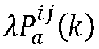

- Where


- A single-differential ambiguity of whole cycles



- Average noise suppression processing is performed through a plurality of moments


- Step 3: the first UE a notifies the target UE c of the first clock offset

- A clock offset determination method of a second UE (a target UE) c includes the following.
- Step 1: the second UE c receives configuration signaling of a second downlink PRS, and location information of a reference base station and a non-reference base station; where the second downlink PRS may be a NR C-PRS, the configuration signaling may be positioning dedicated signaling from LMF, or broadcast signaling, exclusive RRC signaling of the UE or DCI signaling from a serving base station.
- Step 2: at a moment T2, the second UE c receives and measures second downlink PRSs of the reference base station and the non-reference base station to obtain a first positioning measurement value (a carrier phase).
- Step 3: the second UE c receives a first clock offset estimated value


- Step 4: the second UE c modifies the first positioning measurement value (the carrier phase) measured in
step 2 based on the second clock offset
- Hypothetically, the first positioning measurement value (the carrier phase)




- Step 5: the second UE c performs downlink positioning based on the second positioning measurement value

- A maximum value of a clock offset between base stations in an existing TDD system is 50 ns or minus 50 ns, and after the above processing, a residual clock offset may be about 1 ns.
- As shown in
Fig. 2 , in anembodiment 2, description is made specific to the first UE of Type 1 (namely, reference UE of a first type), the first UE of Type 2 (namely, reference UE of a second type), and the second UE (namely, target UE) insolution 2. Where the first UE a ofType 1 is special reference UE of the first type for positioning and measurement, the first UE b ofType 2 is special reference UE of the second type for positioning and measurement, a first positioning measurement value measured by the target UE c is a carrier phase measurement value, a PRS is NR C-PRS, a base station i is a reference base station, and a base station j is a non-reference base station. - A clock offset determination method of the first UE of Type 1 (namely, the reference UE of the first type) includes the following.
- Step 1: the first UE a of
Type 1 receives configuration signaling of a first downlink PRS; where the first downlink PRS may be a NR C-PRS; and the configuration signaling may be positioning dedicated signaling from LMF, or broadcast signaling, exclusive RRC signaling of the UE or DCI signaling from a serving base station. - Step 2: at a moment T1, the first UE a of
Type 1 receives and measures first downlink PRSs of the reference base station and the non-reference base station to obtain a first clock offset between the reference base station i and the non-reference base station j. - Hypothetically, the first UE a of
Type 1 measures a C-PRS sent by the base station i and locks a phase to obtain a carrier phase measurement value


- Where

Type 1, and may be obtained through a known location of a base station and a known location of the first UE a ofType 1.


- Hypothetically, the carrier phase measurement value obtained, by the first UE a of
Type 1, by measuring the C-PRS sent by the base station j is

- It may be obtained by subtracting the above two formulas that at the moment k, a single differential carrier phase measurement value

Type 1 specific to the reference base station i and non-reference base station j is:
- Where


Type 1 and the reference base station i as well as the non-reference base station j, and
- A single-differential ambiguity of whole cycles


Type 1, and ambiguity of whole cycles of the double differential is calculated and then put in a single differential formula to obtain ambiguity of whole cycles


- Average noise suppression processing is performed on a plurality of moments

Type 1, of the reference base station i and the non-reference base station j:
- Step 3: the first UE a of
Type 1 receives the first clock offset
Type 2 and a first clock offset
- Through the first clock offset measured by the first UE a of
Type 1 united with two reference UEs (the first UE a ofType 1 and the first UE b of Type 2), a more accurate second clock offset δ̂bij may be worked out between the reference base station i and the non-reference base station j, and there are at least three calculation methods as follows. - Option 1: an arithmetic mean, for example:

- Option 2: a clock offset of reference UE with an optimal channel condition (for example: a channel condition of UE with the largest reference signal receiving power (RSRP) and/or signal to interference plus noise ratio (SINR) is optimal) is used as a second clock offset δ̂bij , for example: the RSRP and/or SINR of reference UE a is larger than the RSRP and/or SINR of reference UE b, that is, the RSRP of the reference UE a is larger than the RSRP of the reference UE b, and/or, the SINR of the reference UE a is larger than the SINR of the reference UE b, so
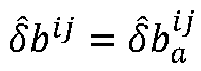

- Option 3: a weighted mean, for example:

- Step 4: the first UE a of
Type 1 notifies the second UE c of the second clock offset δ̂bij . - A clock offset determination method of the first UE of Type 2 (namely, reference UE of the second type) includes the following.
- Step 1: the first UE b of
Type 2 receives configuration signaling of a first downlink PRS; where the first downlink PRS may be a NR C-PRS; and the configuration signaling may be positioning dedicated signaling from LMF, or broadcast signaling, exclusive RRC signaling of the UE or DCI signaling from a serving base station. - Step 2: at the moment T1, the first UE b of
Type 2 receives and measures the first downlink PRS of the reference base station i and the non-reference base station j to obtain a first clock offset between the reference base station i and the non-reference base stationj. According to formula (8) to formula (12), a first clock offset value
Type 2, of the reference base station i and the non-reference base station j may be obtained. - Step 3: the first UE b of
Type 2 feeds the above first clock offset
Type 1. - A clock offset determination method of the second UE (the target UE) includes the following.
- Step 1: the second UE c receives configuration signaling of a second downlink PRS and location information of a reference base station and a non-reference base station; where the second downlink PRS may be a NR C-PRS; and the configuration signaling may be positioning dedicated signaling from LMF, or broadcast signaling, exclusive RRC signaling of the UE or DCI signaling from the serving base station.
- Step 2: at the moment T2, the second UE c receives and measures second downlink PRSs of the reference base station and the non-reference base station to obtain a first positioning measurement value (a carrier phase).
- Step 3: the second UE c receives a second clock offset estimated value δ̂bij fed back by the reference UE a of the first type.
- Step 4: the second UE c modifies the first positioning measurement value (the carrier phase) measured in
step 2 based on the second clock offset to obtain a second positioning measurement value. - Hypothetically, the first positioning measurement value (the carrier phase)


- Step 5: the second UE c performs downlink positioning based on the second positioning measurement value

- A maximum value of a clock offset between base stations in an existing TDD system is 50 ns or minus 50 ns, and after the above processing, a residual clock offset may be about 1 ns.
- As shown in
Fig. 3 , in an embodiment 3, description is made specific to the first UE (namely, the reference UE) and the second UE (namely, target UE) in solution 3; where the first UE a and the first UE b are special reference UE for positioning and measurement, a first positioning measurement value measured by the second UE (the target UE) c is a carrier phase measurement value, a PRS is a NR C-PRS, a base station i is a reference base station, and a base station j is a non-reference base station. - The difference between embodiment 3 and
embodiment 2 is that a plurality of first UEs (the reference UEs) directly notify the second UE (the target UE) of the first clock offsets, and a second clock offset is determined by the target UE. - A clock offset determination method of the first UE (the reference UE) a and b includes the following.
- Step 1: the first UE a and b receive configuration signaling of a first downlink PRS; where the first downlink PRS may be a NR C-PRS; and the configuration signaling may be positioning dedicated signaling from LMF, or broadcast signaling, exclusive RRC signaling of the UE or DCI signaling from a serving base station.
- Step 2: at the moment T1, the first UE a and b receive and measure first downlink PRSs of the reference base station i and the non-reference base station j to obtain a first clock offset between the reference base station i and the non-reference base stationj. According to formulas (1) to (5), a first clock offset value


- Step 3: the first UE a and b notify the target UE c of the first clock offsets


- A clock offset determination method of the second UE (the target UE) c includes the following.
- Step 1: the second UE c receives configuration signaling of a second downlink PRS and location information of a reference base station and a non-reference base station; where the second downlink PRS may be a NR C-PRS; and the configuration signaling may be positioning dedicated signaling from LMF, or broadcast signaling, exclusive RRC signaling of the UE or DCI signaling from a serving base station.
- Step 2: at the moment T2, the second UE c receives and measures second downlink PRSs of the reference base station and the non-reference base station to obtain a first positioning measurement value (a carrier phase).
- Step 3: the second UE c receives first clock offset estimated values


- Through the first clock offset measured by the second UE united with the two first UEs (the first UE a and the first UE b), a more accurate second clock offset δ̂bij between the reference base station i and the non-reference base station j may be worked out, and there are at least three calculation methods as follows.
- Option 1: an arithmetic mean, for example:

- Option 2: a clock offset of reference UE with an optimal channel condition (for example: a channel condition of the UE with the largest RSRP and/or SINR is optimal) is selected as the second clock offset δ̂bij , for example: the RSRP and/or SINR of the reference UE a is larger than the RSRP and/or SINR of the reference UE b, that is, the RSRP of the reference UE a is larger than the RSRP of the reference UE b, and/or, the SINR of the reference UE a is larger than the SINR of the reference UE b, so


- Option 3: a weighted mean, for example:

- Step 4: the second UE c modifies the first positioning measurement value (the carrier phase) measured in
step 2 based on the second clock offset δ̂bij to obtain a second positioning measurement value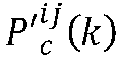
- Hypothetically, the first positioning measurement value (the carrier phase)


- Step 5: the second UE c performs downlink positioning based on the second positioning measurement value

- A maximum value of a clock offset between base stations in an existing TDD system is 50 ns or minus 50 ns, and after the above processing, a residual clock offset may be about 1 ns.
- To sum up, referring to
Fig. 4 , at a first terminal side, an embodiment of the present application provides a clock offset determination method, including the following. - S101, a first positioning measurement value is determined by measuring downlink PRSs from a reference base station and a non-reference base station.
- S102, a first clock offset between the reference base station and the non-reference base station is determined based on the first positioning measurement value.
- S103, a target terminal is assisted to obtain a second clock offset based on the first clock offset.
- Optionally, the step that the target terminal is assisted to obtain the second clock offset based on the first clock offset specifically in one of the following modes:
mode 1, the first clock offset is directly used as the second clock offset, and the target terminal is notified via a Sidelink interface;mode 2, the first clock offset is fed back to a first terminal of a first type via the sidelink interface, the second clock offset is determined by the first terminal of the first type based on the first clock offset and a predefined criterion, and is notified to the target terminal via the Sidelink interface; and mode 3, the target terminal is notified of the first clock offset via the Sidelink interface, and the second clock offset is determined by the target terminal based on the first clock offset and the predefined criterion. - Optionally, the predefined criterion includes one or a combination of the following calculating criteria: an arithmetic mean, selection of the first clock offset with an optimal channel condition value or a weighted mean.
- Optionally, the PRSs include one or a combination of the following signals: a NR PRS, a C-PRS, a SSB or a CSI-RS.
- Correspondingly, referring to
Fig. 5 , at a second terminal side, a clock offset determination method provided by an embodiment of the present application includes the following. - S201, a second clock offset is determined, where the second clock offset is determined based on a first clock offset between a reference base station and a non-reference base station, and the first clock offset is determined based on a first positioning measurement value which is determined by a first terminal by measuring downlink PRSs from the reference base station and the non-reference base station.
- S202, the first positioning measurement value is modified based on the second clock offset to obtain a second positioning measurement value.
- Optionally, the method further includes: performing downlink positioning based on the second positioning measurement value.
- Optionally, the second clock offset is determined in one of the following modes:
mode 1, the first clock offset notified by the first terminal is received via a Sidelink interface, and the first clock offset is used as the second clock offset;mode 2, the second clock offset notified by the first terminal of a first type is received via the Sidelink interface, the second clock offset is determined by the first terminal of the first type based on the first clock offset and a predefined criterion, and the first clock offset is determined by the first terminal of a second type and fed back to the first terminal of the second type via the Sidelink interface; and mode 3, first clock offsets notified by a plurality of first terminals are received via the Sidelink interface, and the second clock offset is determined based on the first clock offsets and the predefined criterion. - Optionally, the predefined criterion includes one or a combination of the following calculating criteria: an arithmetic mean, selection of the first clock offset with an optimal channel condition value, or a weighted mean.
- Optionally, the PRSs include one or a combination of the following signals: a NR PRS, a NR C-PRS, a SSB or a CSI-RS.
- Referring to
Fig. 6 , at a first terminal side, a clock offset determination apparatus provided by an embodiment of the present application includes: afirst unit 11, configured to determine a first positioning measurement value by measuring downlink PRSs from a reference base station and a non-reference base station; and asecond unit 12, configured to determine a first clock offset between the reference base station and the non-reference base station based on the first positioning measurement value; and assist a target terminal to obtain a second clock offset based on the first clock offset. - Optionally, the
second unit 12 is configured to assist the target terminal to obtain the second clock offset based on the first clock offset specifically in one of the following modes:mode 1, the first clock offset is directly used as the second clock offset, and the target terminal is notified via a Sidelink interface;mode 2, the first clock offset is fed back to a first terminal of a first type via the sidelink interface, the second clock offset is determined by the first terminal of the first type based on the first clock offset and a predefined criterion, and is notified to the target terminal via the Sidelink interface; and mode 3, the target terminal is notified of the first clock offset via the Sidelink interface, and the second clock offset is determined by the target terminal based on the first clock offset and the predefined criterion. - Optionally, the predefined criterion includes one or a combination of the following calculating criteria: an arithmetic mean, selection of the first clock offset with an optimal channel condition value or a weighted mean.
- Optionally, the PRSs include one or a combination of the following signals: a NR PRS, a NR C-PRS, a SSB or a CSI-RS.
- Referring to
Fig. 7 , at a second terminal side, a clock offset determination apparatus provided by an embodiment of the present application includes: athird unit 21, configured to determine a second clock offset, where the second clock offset is determined based on a first clock offset between a reference base station and a non-reference base station, and the first clock offset is determined based on a first positioning measurement value which is determined by a first terminal by measuring downlink PRSs from the reference base station and the non-reference base station; and afourth unit 22, configured to modify the first positioning measurement value based on the second clock offset to obtain a second positioning measurement value. - Optionally, the
fourth unit 22 is further configured to: perform downlink positioning based on the second positioning measurement value. - Optionally, the
third unit 21 is configured to determine the second clock offset in one of the following modes:mode 1, the first clock offset notified by the first terminal is received via a Sidelink interface, and the first clock offset is used as the second clock offset;mode 2, the second clock offset notified by the first terminal of a first type is received via the Sidelink interface, the second clock offset is determined by the first terminal of the first type based on the first clock offset and a predefined criterion, and the first clock offset is determined by the first terminal of a second type and fed back to the first terminal of the second type via the Sidelink interface; and mode 3, first clock offsets notified by a plurality of first terminals are received via the Sidelink interface, and the second clock offset is determined based on the first clock offsets and the predefined criterion. - Optionally, the predefined criterion includes one or a combination of the following calculating criteria: an arithmetic mean, selection of the first clock offset with an optimal channel condition value, or a weighted mean.
- Optionally, the PRSs include one or a combination of the following signals: a NR PRS, a NR C-PRS, a SSB or a CSI-RS.
- Referring to
Fig. 8 , a terminal provided by an embodiment of the present application includes aprocessor 600 and amemory 620. - When the terminal is used as a first terminal, the
processor 600 is configured to read a program in thememory 620 and execute the following process: a first positioning measurement value is determined by measuring downlink PRSs from a reference base station and a non-reference base station; a first clock offset between the reference base station and the non-reference base station is determined based on the first positioning measurement value; and a target terminal is assisted to obtain a second clock offset based on the first clock offset. - Optionally, the
processor 600 is configured to assist the target terminal to obtain the second clock offset specifically in one of the following modes based on the first clock offset:mode 1, the first clock offset is directly used as the second clock offset, and the target terminal is notified via the Sidelink interface;mode 2, the first clock offset is fed back to the first terminal of the first type via the Sidelink interface, the second clock offset is determined by the first terminal of the first type based on the first clock offset and a predefined criterion, and is notified to the target terminal via the Sidelink interface; and mode 3, the target terminal is notified of the first clock offset via the Sidelink interface, and the second clock offset is determined by the target terminal based on the first clock offset and the predefined criterion. - Optionally, the predefined criterion includes one or a combination of the following calculating criteria: an arithmetic mean, selection of the first clock offset with an optimal channel condition value, or a weighted mean.
- Optionally, the PRSs include one or a combination of the following signals: a NR PRS, a NR C-PRS, a SSB or a CSI-RS.
- Besides, when the terminal is used as the second terminal, the
processor 600 is further configured to: determine a second clock offset, where the second clock offset is determined based on the first clock offset between the reference base station and the non-reference base station, and the first clock offset is determined based on the first positioning measurement value which is determined by the first terminal by measuring the downlink PRSs from the reference base station and the non-reference base station; and modify the first positioning measurement value based on the second clock offset to obtain a second positioning measurement value. - Optionally, the
processor 600 is further configured to: perform downlink positioning based on the second positioning measurement value. - Optionally, the
processor 600 is configured to determine the second clock offset in one of the following modes:mode 1, the first clock offset notified by the first terminal is received via the Sidelink interface, and the first clock offset is used as the second clock offset;mode 2, the second clock offset notified by the first terminal of a first type is received via the Sidelink interface, the second clock offset is determined by the first terminal of the first type based on the first clock offset and a predefined criterion, and the first clock offset is determined by the first terminal of a second type and fed back to the first terminal of the second type via the Sidelink interface; and mode 3, first clock offsets notified by a plurality of first terminals are received via the Sidelink interface, and the second clock offset is determined based on the first clock offsets and the predefined criterion. - Optionally, the predefined criterion includes one or a combination of the following calculating criteria: an arithmetic mean, selection of the first clock offset with an optimal channel condition value, or a weighted mean.
- Optionally, the PRSs include one or a combination of the following signals: a NR PRS, a NR C-PRS, a SSB or a CSI-RS.
- A
transceiver 610 is configured to receive and send data under control of theprocessor 600. - In
Fig. 8 , a bus architecture may include any quantity of interconnected buses and bridges, specifically linking various circuits of one or more processors represented by theprocessor 600 and memories represented by thememory 620. The bus architecture may also link various other circuits such as a peripheral device, a voltage stabilizer and a power management circuit, which is known in the art and therefore will not be further described herein. A bus interface provides an interface. Thetransceiver 610 may be a plurality of components, including a transmitter and a receiver and providing a unit for communicating with various other apparatuses on a transmission medium. As for different user equipment, auser interface 630 may also be an interface capable of being internally or externally connected with a needed device, and the needed device includes but is not limited to a keypad, a display, a speaker, a microphone, a joystick, etc. - The
processor 600 is responsible for managing the bus architecture and general processing. Thememory 620 can store data used during executing of operations by theprocessor 600. - Optionally, the
processor 600 may be a central processing unit (CPU), an application specific integrated circuit (ASIC), a field-programmable gate array (FPGA) or a complex programmable logic device (CPLD). - It needs to be noted that dividing of units in the embodiment of the present application is exemplary, which is only dividing of logical functions and may have other dividing modes during actual implementation. Besides, all functional units in all embodiments of the present application may be integrated into one processing unit, or all the units may physically and independently exist, or two or more units may be integrated into one unit. The above integrated unit may be realized by using a hardware form or a software functional unit form.
- The integrated unit, if realized in the software functional unit form and sold or applied as an independent product, can be stored in a computer readable storage medium. Based on understanding like this, the technical solutions of the present application essentially or a part of them making contributions on an existing art or all or a part of the technical solutions may be embodied in a form of a software product, the computer software product is stored in a storage medium and includes several instructions for making a computer device (may be a personal computer, a server or a network device, etc.) or a processor execute all or a part of steps of the method of each embodiment of the present application. The above mentioned storage medium includes: a USB flash disk, a mobile hard disk, a read-only memory (ROM), a random access memory (RAM), a diskette or an optical disk and various media capable of storing program codes.
- An embodiment of the present application provides a computing device. The computing device may be, specifically, a desktop computer, a portable computer, a smartphone, a tablet computer, a personal digital assistant (PDA), etc. The computing device may include a CPU, a memory, an input/output device, etc. An input device may include a keyboard, a mouse, a touch screen, etc. An output device may include a display device, such as a liquid crystal display (LCD), a cathode ray tube (CRT), etc.
- The memory may include the ROM and the RAM and provide a program instruction and data stored in the memory for the processor. In the embodiment of the present application, the memory may be configured to store a program of any method provided by the embodiment of the present application.
- The processor, by calling the program instruction stored in the memory, is configured to execute any method provided by the embodiment of the present application according to the obtained program instruction.
- An embodiment of the present application provides a computer storage medium, configured to store a computer program instruction used for the apparatus provided by the embodiment of the present application and containing a program for executing any method provided by the embodiments of the present application.
- The computer storage medium may be any computer readable applicable medium or data storage device and includes but is not limited to a magnetic memory (for example, a floppy disk, a hard disk, a tape, a magneto-optical disk (MO), etc.), an optical memory (for example, CD, DVD, BD, high-definition versatile disc (HVD), etc.), and a semiconductor memory (for example, ROM, erasable programmable read-only memory (EPROM), electrically erasable programmable read only memory (EEPROM), a nonvolatile memory (NAND FLASH), a solid state disk (SSD)), etc.
- The method provided by the embodiments of the present application may be applied to a terminal device, or applied to a network device.
- The terminal device may be also called UE, a mobile station (MS), a mobile terminal, etc. Optionally, the terminal may have capacity of communicating with one or more core networks via a RAN, for example, the terminal may be a mobile phone (or called "cellular" phone), or a mobile computer, etc., for example, the terminal may be also a portable, pocket, handheld, computer built-in or vehicle-mounted mobile apparatus.
- The network device may be a base station (for example, an access point) and refer to a device communicating with a wireless terminal through one or a plurality of sectors on an air interface in an access network. A base station may be used for interconversion of a received air frame and IP grouping and serves as a router between the wireless terminal and other parts of the access network, wherein the other parts of the access network may include an IP network. The base station may also coordinate attribute management of the air interface. For example, the base station may be a base transceiver station (BTS) in GSM or CDMA, or a base station (NodeB) in WCDMA, or an evolutional base station (NodeB or eNB or e-NodeB) in LTE, or gNB in a 5G system, etc. The embodiment of the present application does not make a limitation.
- A processing flow of the above method may be realized by a software program, the software program may be stored in a storage medium, and when the stored software program is called, steps of the above method are executed.
- To sum up, the technical solution provided by the embodiments of the present application includes the following.
- First of all, the single first UE or the plurality of first UEs (namely, reference UEs) simultaneously measure the downlink PRSs from the reference base station and the non-reference base station so as to obtain the first positioning measurement value (namely, the carrier phase measurement value), and further calculation is performed to obtain the first clock offset between the reference base station and the non-reference base station.
- Then the first UE assists target UE to obtain the second clock offset by using three modes:
mode 1, the single first UE directly uses the first clock offset as the second clock offset, and notifies the target UE via the Sidelink interface;mode 2, the plurality of first UEs of Type 2 (namely, the reference UEs of the second type) feed the first clock offsets back to the first UE of Type 1 (namely, the reference UE of the first type) via the Sidelink interface, the second clock offset is determined by the first UE ofType 1 based on the first clock offsets and the predefined criterion, and then the first UE ofType 1 notifies the second UE (namely, the target UE) of the second clock offset via the Sidelink interface; and mode 3, the plurality of first UEs notify the second UE of the first clock offsets via the Sidelink interface, and the second clock offset is determined by the second UE based on the first clock offsets and the predefined criterion. - Then the second UE modifies a first positioning measurement value based on the second clock offset to obtain a second positioning measurement value.
- Finally, the second UE performs downlink positioning (a positioning solution based on the carrier phase) based on the second positioning measurement value after modifying.
- The first UE (namely, the reference UE) may be common UE, or special UE for positioning, or a road test device. In
mode 2, the first UE contains two types: the first UE of Type 1 (namely, the reference UE of the first type) and the first UE of Type 2 (namely, the reference UE of the second type). The PRS may be any downlink signal and include but is not limited to: a NR PRS, a NR C-PRS, a SSB and a CSI-RS, etc. The predefined criterion includes but is not limited to the arithmetic mean, selection of the first clock offset with an optimal channel condition value and the weighted mean. - Therefore, the embodiments of the present application provide the clock offset calibration solution between base stations based on the carrier phase and UE-based positioning. A problem that the positioning algorithm accuracy of an existing single-differential solution is limited by limited clock offset measurement accuracy of a PRS signal, so system positioning property is reduced is solved, for example: a maximum value of a clock offset between base stations in an existing TDD system is 50 ns or minus 50 ns, and after the above processing, a residual clock offset may be about 1 ns. Compared with a UE-assisted positioning solution, the present solution can effectively reduce time delay.
- Those skilled in the art should understand that the embodiments of the present application may be provided as a method, a system, or a computer program product. Therefore, the present application may adopt a complete hardware embodiment, a complete software embodiment or a form of embodiment combining software and hardware. Besides, the present application may adopt a form of a computer program product implemented on one or more computer applicable storage media (including but not limited to a magnetic disk memory, an optical memory, etc.) containing a computer applicable program code.
- The present application is described with reference to flowcharts and/or block diagrams of a method, a device (system), and a computer program product. It should be understood that each flow and/or block and a combination of flows and/or blocks in the flowcharts and/or the block diagrams can be realized by the computer program instructions. These computer program instructions can be provided to a general-purpose computer, a special-purpose computer, an embedded processor or processors of other programmable data processing devices so as to generate a machine, so that an instruction executed by the computer or the processors of other programmable data processing devices generates an apparatus for realizing functions specified in one or more flows in the flowcharts and/or one or more blocks in the block diagrams.
- These computer program instructions may be also stored in computer readable memory capable of guiding the computer or other programmable data processing devices to work in a specific mode, so that the instruction stored in the computer readable memory generates a manufactured product including an instruction apparatus, and the instruction apparatus realizes the functions specified in one or more flows in the flowcharts and/or one or more blocks in the block diagrams.
- These computer program instructions may be also loaded onto a computer or other programmable data processing devices, so that the computer or other programmable devices can execute a series of operation steps to generate processing realized by the computer, so the instructions executed on the computer or other programmable devices provide steps for realizing the functions specified in one or more flows in the flowcharts and/or one or more blocks in the block diagrams.
- Apparently, those skilled in the art can make various changes and transformations to the present application without departing from the spirit and scope of the present application. In this case, if these changes and transformations of the present application fall within the scope of the claims and their equivalents of the present application, the present application also intends to contain these changes and transformations.
Claims (21)
- A clock offset determination method, comprising:determining a first positioning measurement value by measuring downlink positioning reference signals, PRSs, from a reference base station and a non-reference base station;determining a first clock offset between the reference base station and the non-reference base station based on the first positioning measurement value; andassisting a target terminal to obtain a second clock offset based on the first clock offset.
- The method according to claim 1, wherein the assisting the target terminal to obtain the second clock offset based on the first clock offset is specifically in one of:mode 1, directly using the first clock offset as the second clock offset, and notifying the target terminal via a Sidelink interface;mode 2, feeding, via a sidelink interface, the first clock offset back to a first terminal of a first type, for determining the second clock offset based on the first clock offset and a predefined criterion and notifying the target terminal of the second clock offset via the Sidelink interface; andmode 3, notifying, via a Sidelink interface, the first clock offset to the target terminal, for determining the second clock offset based on the first clock offset and the predefined criterion.
- The method according to claim 2, wherein the predefined criterion comprises one or a combination of: an arithmetic mean, selection of the first clock offset with an optimal channel condition value or a weighted mean.
- The method according to claim 1, wherein the PRSs comprise one or a combination of:
a new radio, NR, PRS; a NR carrier phase positioning reference signal, C-PRS; a synchronizing signal block, SSB; or a channel state indication reference signal, CSI-RS. - A clock offset determination method, comprising:determining a second clock offset, wherein the second clock offset is determined based on a first clock offset between a reference base station and a non-reference base station, and the first clock offset is determined based on a first positioning measurement value which is determined by a first terminal by measuring downlink positioning reference signals, PRSs, from the reference base station and the non-reference base station; andmodifying the first positioning measurement value based on the second clock offset to obtain a second positioning measurement value.
- The method according to claim 5, further comprising:
performing downlink positioning based on the second positioning measurement value. - The method according to claim 5, wherein the second clock offset is determined in one of:mode 1, receiving the first clock offset notified by the first terminal via a Sidelink interface, and using the first clock offset as the second clock offset;mode 2, receiving the second clock offset notified by the first terminal of a first type via a Sidelink interface, wherein the second clock offset is determined by the first terminal of the first type based on the first clock offset and a predefined criterion, and the first clock offset is determined by the first terminal of a second type and fed back to the first terminal of the second type via the Sidelink interface; andmode 3, receiving first clock offsets notified by a plurality of first terminals via a Sidelink interface, and determining the second clock offset based on the first clock offsets and the predefined criterion.
- The method according to claim 7, wherein the predefined criterion comprises one or a combination of: an arithmetic mean, selection of the first clock offset with an optimal channel condition value, or a weighted mean.
- The method according to claim 5, wherein the PRSs comprise one or a combination of:
a new radio, NR, PRS; a NR carrier phase positioning reference signal, C-PRS; a synchronizing signal block, SSB; or a channel state indication reference signal, CSI-RS. - A terminal, comprising a processor and a memory;wherein the memory is configured to store a program instruction; andthe processor is configured to read the program instruction in the memory and execute the method according to any one of claims 1 to 4.
- A terminal, comprising a processor and a memory;wherein the memory is configured to store a program instruction; andthe processor is configured to read the program instruction in the memory and execute the method according to any one of claims 5 to 9.
- A clock offset determination apparatus, comprising:a first unit, configured to determine a first positioning measurement value by measuring downlink positioning reference signals, PRSs, from a reference base station and a non-reference base station; anda second unit, configured to determine a first clock offset between the reference base station and the non-reference base station based on the first positioning measurement value; and assist a target terminal to obtain a second clock offset based on the first clock offset.
- The apparatus according to claim 12, wherein the second unit is configured to assist the target terminal to obtain the second clock offset based on the first clock offset specifically in one of:mode 1, directly using the first clock offset as the second clock offset, and notifying the target terminal via a Sidelink interface;mode 2, feeding, via a sidelink interface, the first clock offset back to a first terminal of a first type, for determining the second clock offset based on the first clock offset and a predefined criterion and notifying the target terminal of the second clock offset via the Sidelink interface; andmode 3, notifying, via a Sidelink interface, the first clock offset to the target terminal, for determining the second clock offset based on the first clock offset and the predefined criterion.
- The apparatus according to claim 13, wherein the predefined criterion comprises one or a combination of: an arithmetic mean, selection of the first clock offset with an optimal channel condition value or a weighted mean.
- The apparatus according to claim 12, wherein the PRSs comprise one or a combination of:
a new radio, NR, PRS; a NR carrier phase positioning reference signal, C-PRS; a synchronizing signal block, SSB; or a channel state indication reference signal, CSI-RS. - A clock offset determination apparatus, comprising:a third unit, configured to determine a second clock offset, wherein the second clock offset is determined based on a first clock offset between a reference base station and a non-reference base station, and the first clock offset is determined based on a first positioning measurement value which is determined by a first terminal by measuring downlink positioning reference signals, PRSs, from the reference base station and the non-reference base station; anda fourth unit, configured to modify the first positioning measurement value based on the second clock offset to obtain a second positioning measurement value.
- The apparatus according to claim 16, wherein the fourth unit is further configured to:
perform downlink positioning based on the second positioning measurement value. - The apparatus according to claim 16, wherein the third unit is configured to determine the second clock offset in one of:mode 1, receiving the first clock offset notified by the first terminal via a Sidelink interface, and using the first clock offset as the second clock offset;mode 2, receiving the second clock offset notified by the first terminal of a first type via a Sidelink interface, wherein the second clock offset is determined by the first terminal of the first type based on the first clock offset and a predefined criterion, and the first clock offset is determined by the first terminal of a second type and fed back to the first terminal of the second type via the Sidelink interface; andmode 3, receiving first clock offsets notified by a plurality of first terminals via a Sidelink interface, and determining the second clock offset based on the first clock offsets and the predefined criterion.
- The apparatus according to claim 18, wherein the predefined criterion comprises one or a combination of: an arithmetic mean, selection of the first clock offset with an optimal channel condition value, or a weighted mean.
- The apparatus according to claim 16, wherein the PRSs comprise one or a combination of:
a new radio, NR, PRS; a NR carrier phase positioning reference signal, C-PRS; a synchronizing signal block, SSB; or a channel state indication reference signal, CSI-RS. - A computer storage medium, wherein the computer storage medium stores a computer executable instruction which is configured to make a computer execute the method according to any one of claims 1 to 4 or the method according to any one of claims 5 to 9.
Applications Claiming Priority (2)
| Application Number | Priority Date | Filing Date | Title |
|---|---|---|---|
| CN201911096940.4A CN112788733B (en) | 2019-11-11 | 2019-11-11 | Clock deviation determining method and device |
| PCT/CN2020/126222 WO2021093642A1 (en) | 2019-11-11 | 2020-11-03 | Clock offset determination method and apparatus |
Publications (4)
| Publication Number | Publication Date |
|---|---|
| EP4061068A1 true EP4061068A1 (en) | 2022-09-21 |
| EP4061068A4 EP4061068A4 (en) | 2023-01-04 |
| EP4061068C0 EP4061068C0 (en) | 2026-02-18 |
| EP4061068B1 EP4061068B1 (en) | 2026-02-18 |
Family
ID=75749075
Family Applications (1)
| Application Number | Title | Priority Date | Filing Date |
|---|---|---|---|
| EP20886435.5A Active EP4061068B1 (en) | 2019-11-11 | 2020-11-03 | Clock offset determination method and apparatus |
Country Status (7)
| Country | Link |
|---|---|
| US (1) | US11988754B2 (en) |
| EP (1) | EP4061068B1 (en) |
| JP (1) | JP7413527B2 (en) |
| KR (1) | KR102932974B1 (en) |
| CN (1) | CN112788733B (en) |
| TW (1) | TWI801768B (en) |
| WO (1) | WO2021093642A1 (en) |
Cited By (1)
| Publication number | Priority date | Publication date | Assignee | Title |
|---|---|---|---|---|
| WO2024100744A1 (en) * | 2022-11-07 | 2024-05-16 | 株式会社Nttドコモ | Terminal, base station, and communication method |
Families Citing this family (17)
| Publication number | Priority date | Publication date | Assignee | Title |
|---|---|---|---|---|
| US11044693B1 (en) * | 2020-05-08 | 2021-06-22 | Qualcomm Incorporated | Efficient positioning enhancement for dynamic spectrum sharing |
| US12041511B2 (en) * | 2020-10-02 | 2024-07-16 | Qualcomm Incorporated | Measurement of a downlink positioning reference signal from a non-serving base station of a user equipment at a serving base station of the user equipment |
| BR112023017878A2 (en) * | 2021-03-12 | 2023-10-10 | Qualcomm Inc | DOUBLE DIFFERENTIAL TIMING PROCEDURES AND INDICATION OF A REFERENCE SIGNAL REQUIRED FOR THE POSITIONING MEASUREMENT SET |
| WO2022219249A1 (en) * | 2021-04-16 | 2022-10-20 | Koherent Oy | Method and arrangement for determining a clock offset between at least two radio units |
| GB2606371B (en) * | 2021-05-05 | 2023-11-22 | Samsung Electronics Co Ltd | Method and network |
| US12356358B2 (en) * | 2021-06-09 | 2025-07-08 | Qualcomm Incorporated | Position estimation based on time bias between base station and reference user equipment |
| US20230098682A1 (en) * | 2021-09-30 | 2023-03-30 | Qualcomm Incorporated | Assistance data for position estimation using carrier phase combination in a cellular positioning system |
| US12010072B2 (en) * | 2022-03-17 | 2024-06-11 | Avago Technologies International Sales Pte. Limited | Timing skew calibration in time-interleaved data converters in carrier aggregation |
| WO2023186135A1 (en) * | 2022-03-31 | 2023-10-05 | 华为技术有限公司 | Method for determining positioning information, and positioning method and related apparatuses |
| CN117204073A (en) * | 2022-04-08 | 2023-12-08 | 北京小米移动软件有限公司 | Downlink positioning methods, devices, equipment and storage media |
| CN116961717A (en) * | 2022-04-13 | 2023-10-27 | 中国移动通信有限公司研究院 | An information configuration method and device, communication equipment |
| CN119096158B (en) * | 2022-04-27 | 2026-02-17 | 诺基亚技术有限公司 | Enhanced positioning measurement |
| CN117015031A (en) * | 2022-04-29 | 2023-11-07 | 大唐移动通信设备有限公司 | Information transmission method, carrier phase positioning method and device |
| CN115669114A (en) * | 2022-08-12 | 2023-01-31 | 北京小米移动软件有限公司 | Positioning method and device thereof |
| CN121693891A (en) * | 2023-08-11 | 2026-03-17 | Lg电子株式会社 | Method for performing positioning of terminal in wireless communication system and apparatus therefor |
| CN117082612B (en) * | 2023-10-16 | 2023-12-29 | 深圳市鑫雅达机电工程有限公司 | Cluster type control method and device for motor |
| CN120028746A (en) * | 2023-11-23 | 2025-05-23 | 大唐移动通信设备有限公司 | Terminal positioning method, electronic equipment and device |
Family Cites Families (18)
| Publication number | Priority date | Publication date | Assignee | Title |
|---|---|---|---|---|
| US6377209B1 (en) * | 1997-02-03 | 2002-04-23 | Snaptrack, Inc. | Method and apparatus for satellite positioning system (SPS) time measurement |
| DE69936990T2 (en) * | 1999-10-06 | 2008-01-10 | Matsushita Electric Industrial Co., Ltd., Kadoma | Location system for a mobile telephone network |
| US6665541B1 (en) * | 2000-05-04 | 2003-12-16 | Snaptrack, Incorporated | Methods and apparatuses for using mobile GPS receivers to synchronize basestations in cellular networks |
| US6937872B2 (en) * | 2002-04-15 | 2005-08-30 | Qualcomm Incorporated | Methods and apparatuses for measuring frequencies of basestations in cellular networks using mobile GPS receivers |
| GB2480191A (en) * | 2007-02-02 | 2011-11-09 | Ubiquisys Ltd | Determining the location of a base station |
| US20100164789A1 (en) * | 2008-12-30 | 2010-07-01 | Gm Global Technology Operations, Inc. | Measurement Level Integration of GPS and Other Range and Bearing Measurement-Capable Sensors for Ubiquitous Positioning Capability |
| EP2464989A2 (en) | 2009-08-13 | 2012-06-20 | InterDigital Patent Holdings, Inc. | Method and apparatus for supporting positioning measurements |
| CN103906228B (en) * | 2012-12-28 | 2018-04-10 | 中国电信股份有限公司 | Base station Differential positioning method, positioner and the system of mobile terminal |
| WO2015048986A1 (en) | 2013-10-01 | 2015-04-09 | Telefonaktiebolaget L M Ericsson (Publ) | Synchronization module and method |
| US9964626B2 (en) | 2014-07-24 | 2018-05-08 | Lg Electronics Inc. | Positioning method and apparatus therefor in wireless communication system |
| WO2016159713A1 (en) | 2015-04-01 | 2016-10-06 | 엘지전자 주식회사 | Method for executing rstd measurement-related operation in wireless communication system |
| CN108370551B (en) * | 2015-12-28 | 2020-07-24 | 华为技术有限公司 | Positioning method based on arrival time difference, user equipment and network equipment |
| US11122535B2 (en) * | 2016-07-15 | 2021-09-14 | Qualcomm Incorporated | Techniques for locating devices using narrowband positioning reference signals |
| EP3306337A1 (en) | 2016-10-10 | 2018-04-11 | Fraunhofer Gesellschaft zur Förderung der Angewand | User equipment localization in a mobile communication network |
| CN108112071B (en) * | 2016-11-11 | 2021-07-20 | 中兴通讯股份有限公司 | Positioning method, positioning base station, positioning server and positioning system |
| CN106658707A (en) * | 2016-12-15 | 2017-05-10 | 广州极飞科技有限公司 | Differential positioning system and unmanned aerial vehicle |
| US10120060B2 (en) * | 2017-02-02 | 2018-11-06 | Qualcomm Incorporated | Location determination using user equipment preconfigured with positioning reference signal information |
| CN109842934B (en) * | 2017-11-24 | 2023-04-07 | 北京三星通信技术研究有限公司 | Positioning method and positioning device of User Equipment (UE) and UE |
-
2019
- 2019-11-11 CN CN201911096940.4A patent/CN112788733B/en active Active
-
2020
- 2020-11-03 JP JP2022527209A patent/JP7413527B2/en active Active
- 2020-11-03 US US17/773,845 patent/US11988754B2/en active Active
- 2020-11-03 EP EP20886435.5A patent/EP4061068B1/en active Active
- 2020-11-03 KR KR1020227019066A patent/KR102932974B1/en active Active
- 2020-11-03 WO PCT/CN2020/126222 patent/WO2021093642A1/en not_active Ceased
- 2020-11-10 TW TW109139104A patent/TWI801768B/en active
Cited By (1)
| Publication number | Priority date | Publication date | Assignee | Title |
|---|---|---|---|---|
| WO2024100744A1 (en) * | 2022-11-07 | 2024-05-16 | 株式会社Nttドコモ | Terminal, base station, and communication method |
Also Published As
| Publication number | Publication date |
|---|---|
| CN112788733A (en) | 2021-05-11 |
| JP2023501552A (en) | 2023-01-18 |
| TW202119832A (en) | 2021-05-16 |
| EP4061068A4 (en) | 2023-01-04 |
| EP4061068C0 (en) | 2026-02-18 |
| WO2021093642A1 (en) | 2021-05-20 |
| JP7413527B2 (en) | 2024-01-15 |
| US20220381922A1 (en) | 2022-12-01 |
| CN112788733B (en) | 2021-11-12 |
| KR102932974B1 (en) | 2026-02-27 |
| TWI801768B (en) | 2023-05-11 |
| US11988754B2 (en) | 2024-05-21 |
| KR20220097960A (en) | 2022-07-08 |
| EP4061068B1 (en) | 2026-02-18 |
Similar Documents
| Publication | Publication Date | Title |
|---|---|---|
| US11988754B2 (en) | Clock offset determination method and apparatus | |
| US12628109B2 (en) | Positioning method and apparatus | |
| US12557061B2 (en) | Positioning method and device | |
| US12155461B2 (en) | Clock offset determination method, clock offset processing method, device, and system | |
| US12231360B2 (en) | Signal communication method and device | |
| US12156171B2 (en) | Signal transmission method and apparatus | |
| US12369135B2 (en) | Information transmission method and device | |
| TWI784342B (en) | Method for determining clock bias, computing device and computer storage medium | |
| US12153151B2 (en) | Method and device for determining positioning measurement |
Legal Events
| Date | Code | Title | Description |
|---|---|---|---|
| STAA | Information on the status of an ep patent application or granted ep patent |
Free format text: STATUS: THE INTERNATIONAL PUBLICATION HAS BEEN MADE |
|
| PUAI | Public reference made under article 153(3) epc to a published international application that has entered the european phase |
Free format text: ORIGINAL CODE: 0009012 |
|
| STAA | Information on the status of an ep patent application or granted ep patent |
Free format text: STATUS: REQUEST FOR EXAMINATION WAS MADE |
|
| 17P | Request for examination filed |
Effective date: 20220607 |
|
| AK | Designated contracting states |
Kind code of ref document: A1 Designated state(s): AL AT BE BG CH CY CZ DE DK EE ES FI FR GB GR HR HU IE IS IT LI LT LU LV MC MK MT NL NO PL PT RO RS SE SI SK SM TR |
|
| A4 | Supplementary search report drawn up and despatched |
Effective date: 20221207 |
|
| RIC1 | Information provided on ipc code assigned before grant |
Ipc: H04W 56/00 20090101AFI20221201BHEP |
|
| DAV | Request for validation of the european patent (deleted) | ||
| DAX | Request for extension of the european patent (deleted) | ||
| GRAP | Despatch of communication of intention to grant a patent |
Free format text: ORIGINAL CODE: EPIDOSNIGR1 |
|
| STAA | Information on the status of an ep patent application or granted ep patent |
Free format text: STATUS: GRANT OF PATENT IS INTENDED |
|
| INTG | Intention to grant announced |
Effective date: 20251014 |
|
| GRAS | Grant fee paid |
Free format text: ORIGINAL CODE: EPIDOSNIGR3 |
|
| GRAA | (expected) grant |
Free format text: ORIGINAL CODE: 0009210 |
|
| STAA | Information on the status of an ep patent application or granted ep patent |
Free format text: STATUS: THE PATENT HAS BEEN GRANTED |
|
| AK | Designated contracting states |
Kind code of ref document: B1 Designated state(s): AL AT BE BG CH CY CZ DE DK EE ES FI FR GB GR HR HU IE IS IT LI LT LU LV MC MK MT NL NO PL PT RO RS SE SI SK SM TR |
|
| REG | Reference to a national code |
Ref country code: CH Ref legal event code: F10 Free format text: ST27 STATUS EVENT CODE: U-0-0-F10-F00 (AS PROVIDED BY THE NATIONAL OFFICE) Effective date: 20260218 Ref country code: GB Ref legal event code: FG4D |
|
| REG | Reference to a national code |
Ref country code: DE Ref legal event code: R096 Ref document number: 602020067274 Country of ref document: DE |
|
| REG | Reference to a national code |
Ref country code: IE Ref legal event code: FG4D |
|
| U01 | Request for unitary effect filed |
Effective date: 20260316 |
|
| U07 | Unitary effect registered |
Designated state(s): AT BE BG DE DK EE FI FR IT LT LU LV MT NL PT RO SE SI Effective date: 20260320 |