EP4060891B1 - Tandem control system for machine tool and method for controlling same - Google Patents
Tandem control system for machine tool and method for controlling same Download PDFInfo
- Publication number
- EP4060891B1 EP4060891B1 EP20903028.7A EP20903028A EP4060891B1 EP 4060891 B1 EP4060891 B1 EP 4060891B1 EP 20903028 A EP20903028 A EP 20903028A EP 4060891 B1 EP4060891 B1 EP 4060891B1
- Authority
- EP
- European Patent Office
- Prior art keywords
- unit
- servo motor
- notch filter
- servo
- command
- Prior art date
- Legal status (The legal status is an assumption and is not a legal conclusion. Google has not performed a legal analysis and makes no representation as to the accuracy of the status listed.)
- Active
Links
Images




Classifications
-
- B—PERFORMING OPERATIONS; TRANSPORTING
- B23—MACHINE TOOLS; METAL-WORKING NOT OTHERWISE PROVIDED FOR
- B23Q—DETAILS, COMPONENTS, OR ACCESSORIES FOR MACHINE TOOLS, e.g. ARRANGEMENTS FOR COPYING OR CONTROLLING; MACHINE TOOLS IN GENERAL CHARACTERISED BY THE CONSTRUCTION OF PARTICULAR DETAILS OR COMPONENTS; COMBINATIONS OR ASSOCIATIONS OF METAL-WORKING MACHINES, NOT DIRECTED TO A PARTICULAR RESULT
- B23Q15/00—Automatic control or regulation of feed movement, cutting velocity or position of tool or work
- B23Q15/007—Automatic control or regulation of feed movement, cutting velocity or position of tool or work while the tool acts upon the workpiece
- B23Q15/12—Adaptive control, i.e. adjusting itself to have a performance which is optimum according to a preassigned criterion
-
- H—ELECTRICITY
- H02—GENERATION; CONVERSION OR DISTRIBUTION OF ELECTRIC POWER
- H02P—CONTROL OR REGULATION OF ELECTRIC MOTORS, ELECTRIC GENERATORS OR DYNAMO-ELECTRIC CONVERTERS; CONTROLLING TRANSFORMERS, REACTORS OR CHOKE COILS
- H02P23/00—Arrangements or methods for the control of AC motors characterised by a control method other than vector control
- H02P23/04—Arrangements or methods for the control of AC motors characterised by a control method other than vector control specially adapted for damping motor oscillations, e.g. for reducing hunting
-
- G—PHYSICS
- G05—CONTROLLING; REGULATING
- G05B—CONTROL OR REGULATING SYSTEMS IN GENERAL; FUNCTIONAL ELEMENTS OF SUCH SYSTEMS; MONITORING OR TESTING ARRANGEMENTS FOR SUCH SYSTEMS OR ELEMENTS
- G05B19/00—Program-control systems
- G05B19/02—Program-control systems electric
- G05B19/18—Numerical control [NC], i.e. automatically operating machines, in particular machine tools, e.g. in a manufacturing environment, so as to execute positioning, movement or co-ordinated operations by means of program data in numerical form
- G05B19/404—Numerical control [NC], i.e. automatically operating machines, in particular machine tools, e.g. in a manufacturing environment, so as to execute positioning, movement or co-ordinated operations by means of program data in numerical form characterised by control arrangements for compensation, e.g. for backlash, overshoot, tool offset, tool wear, temperature, machine construction errors, load, inertia
-
- B—PERFORMING OPERATIONS; TRANSPORTING
- B23—MACHINE TOOLS; METAL-WORKING NOT OTHERWISE PROVIDED FOR
- B23Q—DETAILS, COMPONENTS, OR ACCESSORIES FOR MACHINE TOOLS, e.g. ARRANGEMENTS FOR COPYING OR CONTROLLING; MACHINE TOOLS IN GENERAL CHARACTERISED BY THE CONSTRUCTION OF PARTICULAR DETAILS OR COMPONENTS; COMBINATIONS OR ASSOCIATIONS OF METAL-WORKING MACHINES, NOT DIRECTED TO A PARTICULAR RESULT
- B23Q1/00—Members which are comprised in the general build-up of a form of machine, particularly relatively large fixed members
- B23Q1/0009—Energy-transferring means or control lines for movable machine parts; Control panels or boxes; Control parts
- B23Q1/0045—Control panels or boxes
-
- B—PERFORMING OPERATIONS; TRANSPORTING
- B23—MACHINE TOOLS; METAL-WORKING NOT OTHERWISE PROVIDED FOR
- B23Q—DETAILS, COMPONENTS, OR ACCESSORIES FOR MACHINE TOOLS, e.g. ARRANGEMENTS FOR COPYING OR CONTROLLING; MACHINE TOOLS IN GENERAL CHARACTERISED BY THE CONSTRUCTION OF PARTICULAR DETAILS OR COMPONENTS; COMBINATIONS OR ASSOCIATIONS OF METAL-WORKING MACHINES, NOT DIRECTED TO A PARTICULAR RESULT
- B23Q11/00—Accessories fitted to machine tools for keeping tools or parts of the machine in good working condition or for cooling work; Safety devices specially combined with or arranged in, or specially adapted for use in connection with, machine tools
- B23Q11/0032—Arrangements for preventing or isolating vibrations in parts of the machine
-
- G—PHYSICS
- G05—CONTROLLING; REGULATING
- G05B—CONTROL OR REGULATING SYSTEMS IN GENERAL; FUNCTIONAL ELEMENTS OF SUCH SYSTEMS; MONITORING OR TESTING ARRANGEMENTS FOR SUCH SYSTEMS OR ELEMENTS
- G05B19/00—Program-control systems
- G05B19/02—Program-control systems electric
- G05B19/04—Program control other than numerical control, i.e. in sequence controllers or logic controllers
- G05B19/05—Programmable logic controllers, e.g. simulating logic interconnections of signals according to ladder diagrams or function charts
-
- G—PHYSICS
- G05—CONTROLLING; REGULATING
- G05B—CONTROL OR REGULATING SYSTEMS IN GENERAL; FUNCTIONAL ELEMENTS OF SUCH SYSTEMS; MONITORING OR TESTING ARRANGEMENTS FOR SUCH SYSTEMS OR ELEMENTS
- G05B19/00—Program-control systems
- G05B19/02—Program-control systems electric
- G05B19/18—Numerical control [NC], i.e. automatically operating machines, in particular machine tools, e.g. in a manufacturing environment, so as to execute positioning, movement or co-ordinated operations by means of program data in numerical form
- G05B19/19—Numerical control [NC], i.e. automatically operating machines, in particular machine tools, e.g. in a manufacturing environment, so as to execute positioning, movement or co-ordinated operations by means of program data in numerical form characterised by positioning or contouring control systems, e.g. to control position from one programmed point to another or to control movement along a programmed continuous path
- G05B19/195—Controlling the position of several slides on one axis
-
- G—PHYSICS
- G05—CONTROLLING; REGULATING
- G05B—CONTROL OR REGULATING SYSTEMS IN GENERAL; FUNCTIONAL ELEMENTS OF SUCH SYSTEMS; MONITORING OR TESTING ARRANGEMENTS FOR SUCH SYSTEMS OR ELEMENTS
- G05B19/00—Program-control systems
- G05B19/02—Program-control systems electric
- G05B19/18—Numerical control [NC], i.e. automatically operating machines, in particular machine tools, e.g. in a manufacturing environment, so as to execute positioning, movement or co-ordinated operations by means of program data in numerical form
- G05B19/414—Structure of the control system, e.g. common controller or multiprocessor systems, interface to servo, programmable interface controller
- G05B19/4147—Structure of the control system, e.g. common controller or multiprocessor systems, interface to servo, programmable interface controller characterised by using a programmable interface controller [PIC]
-
- H—ELECTRICITY
- H02—GENERATION; CONVERSION OR DISTRIBUTION OF ELECTRIC POWER
- H02P—CONTROL OR REGULATION OF ELECTRIC MOTORS, ELECTRIC GENERATORS OR DYNAMO-ELECTRIC CONVERTERS; CONTROLLING TRANSFORMERS, REACTORS OR CHOKE COILS
- H02P5/00—Arrangements specially adapted for regulating or controlling the speed or torque of two or more electric motors
- H02P5/74—Arrangements specially adapted for regulating or controlling the speed or torque of two or more electric motors controlling two or more AC dynamo-electric motors
-
- G—PHYSICS
- G05—CONTROLLING; REGULATING
- G05B—CONTROL OR REGULATING SYSTEMS IN GENERAL; FUNCTIONAL ELEMENTS OF SUCH SYSTEMS; MONITORING OR TESTING ARRANGEMENTS FOR SUCH SYSTEMS OR ELEMENTS
- G05B2219/00—Program-control systems
- G05B2219/30—Nc systems
- G05B2219/34—Director, elements to supervisory
- G05B2219/34013—Servocontroller
-
- G—PHYSICS
- G05—CONTROLLING; REGULATING
- G05B—CONTROL OR REGULATING SYSTEMS IN GENERAL; FUNCTIONAL ELEMENTS OF SUCH SYSTEMS; MONITORING OR TESTING ARRANGEMENTS FOR SUCH SYSTEMS OR ELEMENTS
- G05B2219/00—Program-control systems
- G05B2219/30—Nc systems
- G05B2219/34—Director, elements to supervisory
- G05B2219/34027—Dual servo controller, for two motors
-
- G—PHYSICS
- G05—CONTROLLING; REGULATING
- G05B—CONTROL OR REGULATING SYSTEMS IN GENERAL; FUNCTIONAL ELEMENTS OF SUCH SYSTEMS; MONITORING OR TESTING ARRANGEMENTS FOR SUCH SYSTEMS OR ELEMENTS
- G05B2219/00—Program-control systems
- G05B2219/30—Nc systems
- G05B2219/34—Director, elements to supervisory
- G05B2219/34273—Pc and plc and nc integrated, pcnc concept
-
- G—PHYSICS
- G05—CONTROLLING; REGULATING
- G05B—CONTROL OR REGULATING SYSTEMS IN GENERAL; FUNCTIONAL ELEMENTS OF SUCH SYSTEMS; MONITORING OR TESTING ARRANGEMENTS FOR SUCH SYSTEMS OR ELEMENTS
- G05B2219/00—Program-control systems
- G05B2219/30—Nc systems
- G05B2219/41—Servomotor, servo controller till figures
- G05B2219/41166—Adaptive filter frequency as function of oscillation, rigidity, inertia load
-
- G—PHYSICS
- G05—CONTROLLING; REGULATING
- G05B—CONTROL OR REGULATING SYSTEMS IN GENERAL; FUNCTIONAL ELEMENTS OF SUCH SYSTEMS; MONITORING OR TESTING ARRANGEMENTS FOR SUCH SYSTEMS OR ELEMENTS
- G05B2219/00—Program-control systems
- G05B2219/30—Nc systems
- G05B2219/41—Servomotor, servo controller till figures
- G05B2219/41232—Notch filter
-
- G—PHYSICS
- G05—CONTROLLING; REGULATING
- G05B—CONTROL OR REGULATING SYSTEMS IN GENERAL; FUNCTIONAL ELEMENTS OF SUCH SYSTEMS; MONITORING OR TESTING ARRANGEMENTS FOR SUCH SYSTEMS OR ELEMENTS
- G05B2219/00—Program-control systems
- G05B2219/30—Nc systems
- G05B2219/41—Servomotor, servo controller till figures
- G05B2219/41264—Driven by two motors
-
- G—PHYSICS
- G05—CONTROLLING; REGULATING
- G05B—CONTROL OR REGULATING SYSTEMS IN GENERAL; FUNCTIONAL ELEMENTS OF SUCH SYSTEMS; MONITORING OR TESTING ARRANGEMENTS FOR SUCH SYSTEMS OR ELEMENTS
- G05B2219/00—Program-control systems
- G05B2219/30—Nc systems
- G05B2219/41—Servomotor, servo controller till figures
- G05B2219/41293—Inverter, DC-to-AC
-
- H—ELECTRICITY
- H02—GENERATION; CONVERSION OR DISTRIBUTION OF ELECTRIC POWER
- H02P—CONTROL OR REGULATION OF ELECTRIC MOTORS, ELECTRIC GENERATORS OR DYNAMO-ELECTRIC CONVERTERS; CONTROLLING TRANSFORMERS, REACTORS OR CHOKE COILS
- H02P2207/00—Indexing scheme relating to controlling arrangements characterised by the type of motor
- H02P2207/05—Synchronous machines, e.g. with permanent magnets or DC excitation
Definitions
- the memory unit includes a basic data storage unit storing information on a maximum value of a linkage magnetic flux by an equivalent permanent magnet, an angular speed at an operation point, a DC gain of the notch filter unit, an inductance of a winding of a stator of the servo motor unit, a pole constant of the servo motor unit, state winding resistance of the servo motor unit, and a rotator inertia moment of a circuit thermo motor unit, a feedback data storage unit storing location and speed feedback information of the first servo motor generated when operating the first servo motor in parallel to the second servo motor and storing the location and speed feedback information of the second servo motor generated when operating the second servo motor in parallel to the first servo motor, and a real-time data storage unit storing a real-time notch filter coefficient of the notch filter unit calculated by the operating unit and a current resonance attenuation command output from the command unit.
- resonance suppression which occurs during tandem control of the first servo motor and the second servo motor is performed by adjusting, in real time, whether the current transferred to the first servo motor and the second servo motor, respectively is applied through the power conversion unit.
- the torque signal output unit 412 outputs an effective torque signal transferred to the power conversion unit 500 in order to drive the servo motor unit 600 according to the speed signal transferred from the speed signal output unit 411 and the feedback signal transferred from the feedback data storage unit 4312.
- the notch filter control unit 430 calculates the notch filter coefficient of the notch filter unit in real time, and controls whether to apply the current transferred to the power conversion unit by the calculated notch filter coefficient. Specifically, the notch filter control unit 430 calculates a damping coefficient and a natural frequency of the servo motor before initial driving of the tandem control system, and calculates the notch filter coefficient of the notch filter unit.
- the notch filter control unit 430 performs a function of suppression controlling the resonance generated according to the parallel operation of the first server motor 610 and the second servo motor 620 by outputting the resonance attenuation command for blocking the transfer to the power conversion unit 500 through the notch filter unit after the first servo motor 610 and the second servo motor 620 of the servo motor unit 600 are operated in parallel after the initial driving of the tandem control system.
- All of the output unit 410, the notch filter unit 420, and the notch filter control unit 430 may be installed inside the servo drive 400, and a detailed control command decoding program or various processing programs, and driving programs may be separately embedded.
- the output unit 410, the notch filter unit 420, and the notch filter control unit 430 may perform the communication by a predetermined protocol with the numerical control unit 100, the main operation unit 200, the PLC 300, the servo motor unit 600, and the power conversion unit 500.
- the tandem control system for a machine tool removes an unnecessary component as an effect in that as resonance suppression for resonance generated when operating two servo motors in parallel by one power unit and a power conversion unit is performed by a scheme of applying or blocking the current transferred to the power conversion unit by the notch filter unit according to a resonance attenuation command through the notch filter coefficient calculated in real time to achieve miniaturization of the machine tool and the tandem control system for the machine tool and maximize spatial utilization.
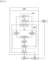
- the memory unit 431 stores various pieces of information for the tandem control for suppressing the resonance generated during the parallel operation of the first servo motor and the second servo motor.
- the operating unit 432 calculates the notch filter coefficient of the notch filter unit 420 in real time through information stored in the memory unit 431.
- the command unit 433 performs the resonance control through the tandem control in real time as the current applied to the power conversion unit is blocked or transferred by the notch filter unit through the resonance attenuation command according to a result of the operating unit 431.
- the memory unit 431, the operating unit 432, and the command unit 433 may be installed inside the notch filter control unit 430, and a detailed control command decoding program or various processing programs, and driving programs may be separately embedded.
- the memory unit 431, the operating unit 432, and the command unit 433 may perform the communication by a predetermined protocol with the numerical control unit 100, the main operation unit 200, the PLC 300, the servo motor unit 600, the power conversion unit 500, the output unit 410, and the notch filter unit 420.
- the memory unit 431 of the notch filter control unit 430 of the servo drive 400 of the tandem control system 1 for the machine tool according to the present invention includes a basic data storage unit 4311, the feedback data storage unit 4312, and a real-time data storage unit 4313.
- the basic data storage unit 4311 stores information on a maximum value of a linkage magnetic flux by an equivalent permanent magnet, an angular velocity at an operation point, a DC gain of the notch filter unit, an inductance of a winding of a stator of the servo motor unit, a pole constant of the servo motor unit, state winding resistance of the servo motor unit, and a rotator inertia moment of a circuit thermo motor unit.
- the operator may perform the basic data storage through the numerical control unit 100 or the main operation unit 200 and also store the basic data in the PLC 300 in the form of the program.
- the feedback data storage unit 4312 stores the location and speed feedback information of the first servo motor generated when operating the first servo motor 610 in parallel to the second servo motor 620 and stores the location and speed feedback information of the second servo motor generated when operating the second servo motor in parallel to the first servo motor.
- the feedback data storage unit 4312 is electrically connected to the output unit 410, the notch filter unit 420, the power conversion unit 500, the real-time data storage unit 4313, the servo motor unit 600, the numerical control unit 100, the main operation unit 200, and the PLC 300 to perform the communication by a predetermined protocol.
- the real-time data storage unit 4313 stores the real-time notch filter coefficients of the notch filter unit calculated by the operating unit and the current resonance attenuation command output from the command unit.
- the real-time data storage unit 4313 is electrically connected to the output unit 410, the notch filter unit 420, the power conversion unit 500, the feedback data storage unit 4312, the servo motor unit 600, the numerical control unit 100, the main operation unit 200, and the PLC 300 to perform the communication by a predetermined protocol.
- the operating unit 432 of the notch filter control unit 430 of the servo drive 400 of the tandem control system 1 for the machine tool according to the present invention includes a damping coefficient calculation unit 4312, a natural frequency calculation unit 4322, a pole calculation unit 4323, a zero point calculation unit 4324, and a coefficient calculation unit 4325.
- the damping coefficient calculation unit 4321 calculates a damping coefficient of the servo motor unit based on data stored in the basic data storage unit.
- the natural frequency calculation unit 4322 calculates a natural frequency of the servo motor unit based on the data stored in the basic data storage unit.
- the pole calculation unit 4323 calculates a pole of the tandem control system based on the data stored in the basic data storage unit, a damping coefficient calculation value of the damping coefficient calculation unit, and a natural frequency calculation value of the natural frequency calculation unit.
- the zero-point calculation unit 4324 calculates a zero point of the notch filter unit based on the data stored in the basic data storage unit, the damping coefficient calculation value of the damping coefficient calculation unit, and the natural frequency calculation value of the natural frequency calculation unit.
- the coefficient calculation unit 4325 calculates a notch filter coefficient based on the data stored in the basic data storage unit, the damping coefficient calculation value of the damping coefficient calculation unit, the natural frequency calculation value of the natural frequency calculation unit, the pole calculation value of the tandem control system of the pole calculation unit, and the zero-point calculation value of the notch filter unit of the zero-calculation unit.
- the coefficient calculation unit 4325 calculates a resonance attenuation command through a pole zero-point offset technique based on the data stored in the basic data storage unit, the damping coefficient calculation value of the damping coefficient calculation unit, the natural frequency calculation value of the natural frequency calculation unit, the pole calculation value of the tandem control system of the pole calculation unit, the zero-point calculation value of the notch filter unit of the zero-calculation unit, and the notch filter coefficient value of the coefficient calculation unit.
- tandem control system for the machine tool as precise resonance suppression control of two servo motors is performed in real time through tandem control utilizing the notch filter unit through the pole-zero point offset technique by suppressing the resonance generated when operating two servo motors in parallel by one power unit and the power conversion unit according to feedback information of the first and second servo motors transferred from a feedback data storage unit in real time, and the notch filter coefficient and a current resonance attenuation command transferred from a data storage unit in real time, the precision and the reliability of the service control device of the automatic tool changer or the automatic palette changer can be maximized, and the stability and processing efficiency of the machine tool can be increased.
- tandem control system for the machine tool as the suppression control of the resonance generated when operating two servo motors in parallel by one power unit and the power conversion unit is automatically performed in real time regardless of the type of servo motor and the capacity of the servo motor, the convenience of the operator is achieved and a non-processing time is minimized, thereby maximizing the productivity of the machine tool.
- a calculation principle of the operating unit 432 and the command unit 433 of the notch filter control unit 430 will be described with reference to FIGS. 5 to 7 . That is, the operating unit 432 and the command unit 433 of the notch filter control unit 430 calculate the notch filter coefficient in real time according to the following principle, and outputs the resonance attenuation command based on the calculated notch filter coefficient.
- Equation 1 the parallel operation tandem control system is too complicated to evaluate the stability.
- Equation 1 is calculated as Equation 2.
- Equation 2 a transfer function obtained from Equation 2
- Equations 3 and 4 are obtained.
- G s ⁇ n 2 s 2 + 2 ⁇ n s + ⁇ n 2
- the pole calculation unit 4323 is calculated by Equation 3.
- Equation 5 K n s 2 + ⁇ ⁇ o Q s + ⁇ o 2 s 2 + ⁇ o Q s + ⁇ o 2
- damping coefficient calculation unit 4321 and the natural frequency calculation unit 4322 are calculated by Equation 4.
- FIG. 7 is a conceptual view for the pole-zero point offset technique in a complex plane. As illustrated in FIG. 7 , in general, response characteristics of the system during control may be interpreted by setting the denominator of the transfer function to 0. Accordingly, the pole of the tandem control system according to Equation 3 is displayed on the complex plane (indicated by the dashed line X in FIG. 7 ).
- the pole of the tandem control system expressed by Equation 3 is close to an imaginary axis, which means that the tandem control system which operates as the power converter resonates. That is, FIG. 7 becomes more stable toward the left with respect to the X-axis of FIG. 7 and shows an unstable state due to resonance toward the right.
- pole ((indicated by a solid line X in FIG. 7 ) is arranged so as to cancel fundamental resonance component of the tandem control system which operates as one power conversion unit and allow the tandem control system to have desired performance by placing the zero point (indicated by a solid line O in FIG. 7 ) of the notch filter, which is the numerator part of Equation 4, at the location of the pole of the tandem control system, which is the denominator of Equation 3, stable tandem control in which the resonance is suppressed is possible, which is expressed by Equation 6.
- G O s H s
- G s K n s 2 + ⁇ ⁇ o Q s + ⁇ o 2 s 2 + ⁇ o Q s + ⁇ o 2 ⁇ ⁇ n 2 s 2 + 2 ⁇ n s + ⁇ n 2
- the resonance attenuation command of the command unit is derived by Equation 6.
- the resonance frequency and the natural frequency of the servo motor of the tandem control system among the notch filter coefficients may be set as in Equation 7.
- ⁇ 0 ⁇ n
- the notch filter coefficient shown in Equation 8 may be obtained.
- the coefficient calculation unit 4325 is derived by Equation 8.
- the tandem control system for a machine tool controls resonance suppression which occurs when operating two servo motors as one power conversion unit and one servo drive in parallel through tandem control by calculating a notch filter coefficient of a notch filter unit in real time by a notch filter control unit and stably setting operating resonance suppression which occurs when operating two servo motors into one power conversion unit and one servo drive in parallel regardless of the type of servo motor or a capacity of the servo motor through tandem control as blocking or applying current transferred to the power conversion unit with the notch filter unit by the calculated notch filter coefficient in real time to enhance convenience of an operator and finally controls an apparatus driven by an automatic tool exchanger or an automatic palette changer to reduce manufacturing cost, and enhance reliability by noise reduction, and the resonance which occurs when operating two servo motors in parallel by one power unit and the power conversion unit are universally used regardless of the type of servo motor and automatically suppression-controlled in real time, to achieve the convenience of the operator and minimize the non-processing time, thereby maximizing
- tandem control system 1 for the machine tool may further include an input unit and a display unit.
- the input unit is installed in the form of a switch or touch button on the operation panel or the main operation unit, etc., and performs a function to allow the operator to arbitrarily select to perform or not to perform the resonance suppression control in real time during parallel operation of the servo motor unit.
- the resonance suppression control function of the tandem control system of the machine tool does not operate.
- the display unit displays the damping coefficient value, natural frequency value, pole calculated value, zero-point calculated value, notch filter coefficient value, resonance attenuation command value, and as a result, the operator may visually check whether the presence and the control state of the resonance suppression when two servo motors of the servo motor unit are operated in parallel in real time.
- the display unit may be constituted by an LCD, LED, PDP monitor, etc., in the main operation unit or the numerical control unit.
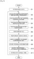
- a method for controlling the tandem control system of a machine tool includes storing basic data (S1), calculating a damping coefficient and a natural frequency of a servo motor unit (S2), calculating a pole of a tandem control system (S3), calculating a zero-point of the notch filter unit (S4), calculating a notch filter coefficient (S5), performing a PLC (S6), performing by a servo drive (S7), applying power of a power conversion unit (S8), storing feedback information (S9), outputting a resonance attenuation command (S10), and storing data in real time (S11).
- S1 basic data
- S2 calculating a damping coefficient and a natural frequency of a servo motor unit
- S3 calculating a pole of a tandem control system
- S4 calculating a zero-point of the notch filter unit
- S5 calculating a notch filter coefficient
- S6 performing a PLC
- S7 performing by a servo drive
- the basic data storage unit 4311 stores basic data for the servo motor unit and the notch filter unit for tandem control.
- the operator may perform information on a maximum value of a linkage magnetic flux by an equivalent permanent magnet, an angular speed at an operation point, a DC gain of the notch filter unit, an inductance of a winding of a stator of the servo motor unit, a pole constant of the servo motor unit, state winding resistance of the servo motor unit, and a rotator inertia moment of a circuit thermo motor unit through the numerical control unit 100 or the main operation unit 200, and stores the information in the PLC 300 in the form of the program.
- the damping coefficient and the natural frequency of the servo motor unit are calculated. That is, the damping coefficient and the natural frequency of the servo motor unit are calculated through Equation 5 by the damping coefficient calculation unit and the natural frequency calculation unit.
- the pole calculation unit of the tandem control system calculates the pole of the tandem control system by Equation 3.
- the zero-point calculation unit of the notch filter unit calculates the zero-point of the notch filter unit by Equation 4.
- the coefficient calculation unit calculates the notch filter coefficient of the notch filter unit by Equation 8 through the basic data stored in the basic data storage unit, the calculated damping coefficient and natural frequency of the servo motor unit, the pole of the tandem control system, and the zero-point of the notch filter unit.
- the PLC After the calculating of the notch filter coefficient (S5), the PLC performs the control command through communication with the numerical control unit or the main operation unit.
- the servo drive After the performing of the PLC (S6), the servo drive performs the control command transferred from the PLC.
- the power conversion unit After the performing by the servo drive (S7), the power conversion unit applies current to the servo motor unit including the first servo motor and the second servo motor according to a signal of the servo drive.
- the feedback data storage unit stores the location and speed feedback information of the first servo motor generated when operating the first servo motor in parallel to the second servo motor and stores the location and speed feedback information of the second servo motor generated when operating the second servo motor in parallel to the first servo motor.
- the command unit After the storing of the feedback information (S9), the command unit outputs the resonance attenuation command by Equation 6 in real time according to the notch filter coefficient calculated by the coefficient calculation unit, and transfers the output resonance attenuation command to the notch filter unit.
- the resonance suppression through the tandem control is performed in real time.
- the method for controlling the tandem control system for the machine tool controls resonance suppression which occurs when operating two servo motors as one power conversion unit and one servo drive in parallel through tandem control by calculating a notch filter coefficient of a notch filter unit in real time by a notch filter control unit and stably setting operating resonance suppression which occurs when operating two servo motors into one power conversion unit and one servo drive in parallel regardless of the type of servo motor or a capacity of the servo motor through tandem control as blocking or applying current transferred to the power conversion unit with the notch filter unit by the calculated notch filter coefficient in real time to enhance convenience of an operator and finally controls an apparatus driven by an automatic tool exchanger or an automatic palette changer to reduce manufacturing cost, and enhance reliability by noise reduction, and can be universally used regardless of the type of servo motor and the capacity of the serve motor, thereby increasing compatibility of the tandem control system, and as resonance suppression is performed by a scheme of applying or blocking the current transferred to the power conversion unit by the notch filter unit according to
- FIG. 6 is a block diagram for a configuration of a notch filter control unit of a servo drive of the tandem control system for a machine tool according to an exemplary embodiment of the present invention
- FIG. 7 is a graph for describing a process of outputting a resonance attenuation command through a pole-zero point offset technique in a command unit of the tandem control system for a machine tool according to an exemplary embodiment of the present invention.
- a solid line indicates a parallel operation of two servo motors in the servo control apparatus in the related art
- a dotted line indicates a state to which the tandem control system and the method for controlling the same according to the present invention are applied.
- the calculation unit calculates the notch filter coefficient of the notch filter unit in real time through Equations 6 and 8
- the command unit reflects the notch filter coefficient and outputs the resonance attenuation command and controls the current supplied to the first servo motor and the second servo motor by blocking or applying the current applied to the power conversion unit to control the resonance suppression during the tandem control of simultaneously controlling two servo motors with one power conversion unit in real time, thereby securing stability and reliability of approximately 5.2 times against disturbance.
Landscapes
- Engineering & Computer Science (AREA)
- Physics & Mathematics (AREA)
- General Physics & Mathematics (AREA)
- Automation & Control Theory (AREA)
- Mechanical Engineering (AREA)
- Power Engineering (AREA)
- Human Computer Interaction (AREA)
- Manufacturing & Machinery (AREA)
- Control Of Multiple Motors (AREA)
- Numerical Control (AREA)
- Control Of Electric Motors In General (AREA)
Description
- The present invention relates to a tandem control system for machine too and a method for controlling the same, and more particularly, to a tandem control system for a machine tool and a method for controlling the same which control resonance suppression which occurs when operating two servo motors as one power conversion unit and one servo drive in parallel through tandem control by calculating a notch filter coefficient of a notch filter unit real time by a notch filter control unit and adjusting an application state of current applied to a power conversion unit by the calculated notch filter coefficient in real time to enhance stability and reliability of a machine tool, enhance convenience of an operator, reducing manufacturing cost and maintenance cost, and promoting miniaturization.
- In general, a machine tool refers to a machine used to process metal/non-metal workpieces in a desired shape and dimension using a suitable tool by using various types of cutting or non-cutting methods.
- Various types of machine tools including a turning center, a vertical/horizontal machining center, a door-type machining center, a Swiss turning machine, an electric discharge machine, a horizontal NC boring machine, a CNC lathe, and a multi-tasking machining center are being widely used in various industrial sites for the purpose of the corresponding work.
- The multi-tasking machining center, among the machine tools, refers to a turning center equipped with a multifunctional automatic tool changer (ATC) and a tool magazine in order to perform various types of processing such as turning machining, drilling, tapping, or milling. In the case of the multi-tasking machining center, an operator manually mounts a tool on a tool magazine when loading the tool required for machining or changing the tools.
- In general, various types of currently used machine tools each have a control panel to which a numerical control (NC) technology or a computerized numerical control (CNC) technology is applied. The control panel is provided with a multifunctional switch or button, and a monitor.
- In addition, the machine tool includes a table on which a material, i.e., a workpiece is seated, and which is transferred to machine the workpiece, a palette used to prepare the workpiece to be machined, a main shaft coupled to a tool or the workpiece and configured to be rotated, and a tailstock and a steady rest configured to support the workpiece during machining.
- In general, the machine tool is provided with a transfer unit configured to transfer the table, a tool post, the main shaft, the tailstock, and the steady rest along a transfer shaft in order to perform various types of machining.
- In general, the machine tool uses a plurality of tools in order to perform various types of machining, and a tool magazine or a turret is used in the form of a tool storage place for receiving and storing the plurality of tools.
- The machine tool uses the plurality of tools in order to perform various types of machining, and the tool magazine is used in the form of a tool storage place for receiving and storing the plurality of tools.
- In general, the machine tool is equipped with the automatic tool changer (ATC) configured to withdraw a specific tool from the tool magazine or remount the tool on the tool magazine based on an instruction of a numerical control unit in order to improve productivity of the machine tool.
- In general, the machine tool is equipped with an automatic palette changer (APC) in order to minimize the non-processing time. The automatic palette changer (APC) automatically changes the palettes between a workpiece machining region and a workpiece loading region. The workpiece may be mounted on the palette.
- In general, in the machine tool, a servo motor is used for driving the automatic tool changer (ATC), the automatic pallet changer (APC), the tailstock, or the vibration isolator.
- As such, a device for finally controlling the ATC or the APC, the tailstock, or the vibration isolator by controlling the servo motor is referred to as a servo control device.
- In particular, when a size is large or large force is required like a large automatic pallet changer (APC), one shaft is driven by operating two servo motors in parallel by productivity and economic factors and a technical factor in which sufficient torque cannot be obtained only by one servo motor, and this is referred to as tandem control.
- However, as illustrated in
FIG. 1 , when two servo motors are used in the related art, one inverter and one servo drive are coupled to one servo motor in each of two servo motors in the servo control device in the related art. That is, the servo motors are operated in a multi inverter multi servo motor scheme in which afirst inverter 20 and afirst servo drive 10 are connected to afirst servo motor 30 and asecond inverter 21 and asecond servo drive 11 are connected to asecond servo motor 31. - However, in the case of the multi inverter multi servo motor, since a separate inverter and a separator servo drive should be combined for each servo motor, there is a problem in that the size of the apparatus, manufacturing cost and maintenance cost increase, and miniaturizing the machine tool cannot be promoted.
- In order to solve such a problem, as illustrated in
FIG. 2 , a single inverter multi servo motor of a scheme of operating oneinverter 20 and oneservo drive 10 in parallel in twoservo motors - However, unlike induction motors with slippage, since servo motors are permanent magnet type synchronous motors, the servo motors have no slippage, and a stable parallel operation is possible only when two servo motors are synchronized so that there is no speed deviation, otherwise, there was a problem in that the stability and reliability of the service control device is lowered, and finally, the stability and reliability and processing precision of the machine tool are lowered.
- In order to solve the resonance suppression control problem, three conventional tandem control systems and control methods thereof are proposed.
- First, a damping control device using an auxiliary inverter and an auxiliary winding, and a method therefor are provided, and this is a structure in which the main inverter and the auxiliary inverter are separately provided, and the servo motor and the auxiliary winding are formed, and problems such as manufacturing cost increases and large amounts of production difficulties still remain.
- Second, as an active damping control device and a method thereof simply set the resonance suppression control as an empirical method, the reliability and stability of the servo control device are not still guaranteed and only the manufacturing cost increases because the active damping control device and the method thereof cannot actively cope with the actual resonance occurrence or many disturbances or variables.
- Third, as by an apparatus and a method for reducing a pulsation using a load oscillation analyzer, the resonance suppression control is calculated by the empirical method, and a sensor capable of detecting the pulsation of the magnetic flux axis current should be provided, the manufacturing cost increases and as the resonance suppression control is performed without considering the actual resonance occurrence or real-time deformation amount according to the operating state of the apparatus, the accuracy and reliability are significantly reduced, and finally, there is a problem in that the machining precision and reliability of the machine tool are reduced.
- Further, in general, there is a method for avoiding the resonance operation band or attenuating the resonance with a notch filter through the three tandem control systems and a control method thereof described above in order to suppress a resonance phenomenon.
- As illustrated in
FIGS. 3 and 4 , the notch filter is generally used to suppress the resonance phenomenon, a resonance frequency (ωO) of the notch filter, coefficients for an attenuation magnitude (α) of the notch filter, and a bandwidth (Q) of the notch filter to find the coefficient should be obtained. - However, in general, there is a problem that the coefficient of the notch filter varies depending on the manufacturing time and design difference even for servo motors of the same model from the same manufacturer, and the coefficient of the notch filter varies depending on the manufacturer even for servo motors of the same capacity.
Moreover, as the resonance frequency, attenuation magnitude, and bandwidth of the notch filter generated during the operation of the machine tool are changed in real time, there a problem in that it takes a lot of time and money for equipment tuning or equipment setting to suppress resonance through tandem control for each machine tool, inconvenience of the operator is caused, and productivity is reduced. - Therefore, the development of a tandem control system for a machine tool using a notch filter and a control method therefore accurately calculate the notch filter coefficient that is changed in real time regardless of the capacity or type of the servomotor, output the resonance attenuation command through the calculated notch filter coefficient, and block the current transmitted to a power converter at a frequency at which resonance occurs by the output resonance attenuation command to suppress resonance.
-
JP 6 049 587 B2
US 2007 / 0 007 926 A1 discloses a servo controller for synchronously controlling a master side drive source to drive one drive axis and a slave side drive source to drive the other drive axis. The servo controller includes a correction data calculation means for calculating correction data to correct a positional deviation of a slave side drive source according to a synchronization error which is a difference between a positional deviation of a master side drive source and a positional deviation of the slave side drive source, in which the correction data is added to the positional deviation of the slave side drive source.
US 2016 / 0 170 400 A1 discloses a servo control device that includes: a speed control loop including a speed command generating unit, a torque command generating unit, and a speed detecting unit; a sine wave disturbance input unit; a frequency response calculating unit estimating a gain and phase of speed control loop input/output signals; a resonance frequency detecting unit; a resonance mode characteristic estimating unit estimating resonance characteristics from the frequency response at a resonance frequency and frequencies therearound; a rigid-body mode characteristic estimating unit estimating rigid-body characteristics from the frequency response in a low-frequency band; a filter attenuating a component in a particular frequency band in a torque command; and a filter adjusting unit making setting so that the filter has specified characteristics. The filter adjusting unit further includes a filter adjusting part attenuating a component in a frequency band corresponding to a resonance mode estimated by the resonance mode characteristic estimating unit. - The present invention has been made in an effort to solve the above-mentioned problems, and an object of the present invention is to provide a tandem control system for a machine tool and a method for controlling the same which control resonance suppression which occurs when operating two servo motors as one power conversion unit and one servo drive in parallel through tandem control by calculating a notch filter coefficient of a notch filter unit in real time by a notch filter control unit and stably setting operating resonance suppression which occurs when operating two servo motors into one power conversion unit and one servo drive in parallel regardless of the type of servo motor or a capacity of the servo motor through tandem control as blocking or applying current transferred to the power conversion unit with the notch filter unit by the calculated notch filter coefficient in real time to enhance convenience of an operator and finally control an apparatus driven by an automatic tool exchanger or an automatic pallet changer to reduce manufacturing cost, enhance reliability by noise reduction, and promote miniaturization of the apparatus.
- Further, another object of the present invention is to provide a tandem control system for a machine tool and a method for controlling the same which calculate the notch filter coefficient in real time by the notch filter control unit and output a resonance attenuation command by a command unit through a pole-zero point offset technique through the calculated notch filter coefficient, and adjust current applied to a first servo motor and a second servo motor by the power conversion unit as by applying the current transferred to the power conversion unit by the notch filter unit to maximize servo control precision, and reliability and stability of the automatic tool changer or the automatic pallet changer regardless of the type of servo motor unit through precise tandem control synchronized at all speeds and locations of two servo motors, and reduce maintenance cost.
- In order to achieve the above-mentioned object, a tandem control system for a machine tool according to
claim 1, and a method according toclaim 4 is provided.
A tandem control system for a machine tool according the present invention includes: a numerical control unit; a main operation unit; a PLC performing a control command through communication with the numerical control unit or the main operation unit; a servo drive having a notch filter unit and performing the control command of the PLC; a servo motor unit driven by controlling the servo drive; and a power conversion unit electrically connected to the servo motor unit and the servo drive to apply current to the servo motor unit, and the servo drive performs resonance suppression according to an operation of the servo motor by adjusting an application state of the current applied to the power conversion unit according to a change in notch filter coefficient of the notch filter unit, which is calculated in real time. - According to the present invention, the servo drive further includes an output unit outputting an operation speed signal of the servo motor unit and a torque signal transferred to the power conversion unit, and a notch filter control unit calculating the notch filter coefficient of the notch filter unit in real time, and controlling whether to apply the current transferred to the power conversion unit by the calculated notch filter coefficient.
- According to the present invention, the servo motor unit includes a first servo motor and a second servo motor connected in parallel to each other, and according to the real-time change of the notch filter coefficient of the notch filter unit, resonance suppression which occurs during tandem control of the first servo motor and the second servo motor is controlled by adjusting, in real time, whether the current transferred to the first servo motor and the second servo motor, respectively is applied through the power conversion unit.
- According to the present invention, the notch filter control unit of the tandem control system for a machine tool includes a memory unit storing information for the tandem control for suppressing the resonance generated during the parallel operation of the first servo motor and the second servo motor, an operating unit calculating the notch filter coefficient of the notch filter unit through the information stored in the memory unit, and a command unit performing the resonance suppression through the tandem control in real time by blocking the current applied to the power conversion unit by the notch filter unit through a resonance attenuation command according to a result of the operating unit.
- Further, according to the present invention, the memory unit includes a basic data storage unit storing information on a maximum value of a linkage magnetic flux by an equivalent permanent magnet, an angular speed at an operation point, a DC gain of the notch filter unit, an inductance of a winding of a stator of the servo motor unit, a pole constant of the servo motor unit, state winding resistance of the servo motor unit, and a rotator inertia moment of a circuit thermo motor unit, a feedback data storage unit storing location and speed feedback information of the first servo motor generated when operating the first servo motor in parallel to the second servo motor and storing the location and speed feedback information of the second servo motor generated when operating the second servo motor in parallel to the first servo motor, and a real-time data storage unit storing a real-time notch filter coefficient of the notch filter unit calculated by the operating unit and a current resonance attenuation command output from the command unit.
- Further, in another exemplary embodiment of the tandem control system for a machine tool according to the present invention, the operating unit of the tandem control system for a machine tool may include a damping coefficient calculation unit calculating a damping coefficient of the servo motor unit by data stored in the basic data storage unit, a natural frequency calculation unit calculating a natural frequency of the servo motor unit by the data stored in the basic data storage unit, a pole calculation unit calculating a pole of the tandem control system based on the data stored in the basic data storage unit, a calculation value of the damping coefficient calculation unit, and a calculation value of the natural frequency calculation unit, a zero-point calculation unit calculating the zero point of the notch filter unit based on the data stored in the basic data storage unit, the calculation value of the damping coefficient calculation unit, and the calculation value of the natural frequency calculation unit, and a coefficient calculation unit calculating the notch filter coefficient based on the data stored in the basic data storage unit, the calculation value of the damping coefficient calculation unit, the calculation value of the natural frequency calculation unit, a calculation value of the pole calculation unit, and a zero-point value of the zero-point calculation unit.
- Further, in another exemplary embodiment of the tandem control system for a machine tool according to the present invention, the command unit of the tandem control system for a machine tool may output a resonance attenuation command through a pole-zero point offset technique based on the data stored in the basic data storage unit, the calculation value of the damping coefficient calculation unit, the calculation value of the natural frequency calculation unit, the calculation value of the pole calculation unit, the zero-point value of the zero-point calculation unit, and a notch filter coefficient value of the coefficient calculation unit.
- Further, in another exemplary embodiment of the tandem control system for a machine tool according to the present invention, the output unit of the tandem control system for a machine tool may include a speed signal output unit outputting an operation speed signal of the servo motor unit according to a location command transferred from the numerical control unit and a feedback signal transferred from the feedback data storage unit, and a torque signal output unit outputting an effective torque signal transferred to the power conversion unit in order to drive the servo motor unit according to a speed signal transferred from the speed signal output unit and the feedback signal transferred from the feedback data storage unit.
- A method for controlling a tandem control system for a machine tool according to the present invention includes: storing basic data for a servo motor unit and a notch filter unit for tandem control; calculating a damping coefficient and a natural frequency of the servo motor unit; calculating a pole of a tandem control system; calculating a zero-point of a notch filter unit; calculating a notch filter coefficient of the notch filter unit through the stored basic data, and the calculated damping coefficient and natural frequency of the servo motor unit, the pole of the tandem control system, and the zero-point of the notch filter unit; performing, by a PLC, a control command for communication with a numerical control unit and or a main cooperation unit; performing, by a servo drive, the control command transferred from the PLC; applying, by a power conversion unit, current to a servo motor unit including a first servo motor and a second servo motor according to a signal of the servo drive; storing location and speed feedback information of the first servo motor generated when operating the first servo motor in parallel to the second servo motor and location and speed feedback information of the second servo motor generated when operating the second servo motor in parallel to the first servo motor; and outputting a resonance attenuation command in real time according to the calculated notch filter coefficient, and resonance suppression through the tandem control may be performed in real time by blocking current applied to the power conversion unit by the notch filter unit through the notch filter coefficient calculated in real time and the resonance attenuation command.
- Further, in another exemplary embodiment of the method for controlling a tandem control system for a machine tool, the method for controlling a tandem control system for a machine tool may further include after the outputting of the resonance attenuation command, storing a current notch filter coefficient calculated in real time and the resonance attenuation command output in real time.
- The tandem control system for a machine tool and the method for controlling the same according to the present invention control resonance suppression which occurs when operating two servo motors as one power conversion unit and one servo drive in parallel through tandem control by calculating a notch filter coefficient of a notch filter unit in real time by a notch filter control unit and stably setting operating resonance suppression which occurs when operating two servo motors into one power conversion unit and one servo drive in parallel regardless of the type of servo motor or a capacity of the servo motor through tandem control as blocking or applying current transferred to the power conversion unit with the notch filter unit by the calculated notch filter coefficient in real time to enhance convenience of an operator and finally control an apparatus driven by an automatic tool exchanger or an automatic pallet changer to reduce manufacturing cost, and enhance reliability by noise reduction, and can be universally used regardless of the type of servo motor and the capacity of the serve motor, thereby increasing compatibility of the tandem control system and the method for controlling the same.
- Further, the tandem control system for a machine tool and the method for controlling the same according to the present invention has an effect in that as resonance suppression for resonance generated when operating two servo motors in parallel by one power unit and a power conversion unit is performed by a scheme of applying or blocking the current transferred to the power conversion unit by the notch filter unit according to a resonance attenuation command through the notch filter coefficient calculated in real time, an unnecessary component is removed to achieve miniaturization of the machine tool and the tandem control system for the machine tool and maximize spatial utilization.
- Moreover, the tandem control system for a machine tool and the method for controlling the same according to the present invention has an effect in that as precise resonance suppression control of two servo motors is performed in real time through tandem control utilizing the notch filter unit through the pole-zero point offset technique by suppressing the resonance generated when operating two servo motors in parallel by one power unit and the power conversion unit according to feedback information of the first and second servo motors transferred from a feedback data storage unit in real time, and the notch filter coefficient and a current resonance attenuation command transferred from a data storage unit in real time, the precision and the reliability of the service control device of the automatic tool changer or the automatic pallet changer can be maximized, and the stability and processing efficiency of the machine tool can be increased.
- Moreover, the tandem control system for a machine tool and the method for controlling the same according to the present invention has an effect in that as the suppression control of the resonance generated when operating two servo motors in parallel by one power unit and the power conversion unit is automatically performed in real time regardless of the type of servo motor and the capacity of the servo motor, the convenience of the operator is achieved and a non-processing time is minimized, thereby maximizing the productivity of the machine tool.
-
-
FIG. 1 is a conceptual view of a multi inverter multi servo motor in which one inverter and one servo drive are combined with one servo motor in the related art. -
FIG. 2 is a conceptual view of a single inverter multi servo motor in which one inverter and one servo drive are combined with two servo motors to perform tandem control in the related art. -
FIGS. 3 and 4 are graphs for describing frequency characteristics of a notch filter in the related art. -
FIG. 5 is a block diagram for a configuration of a tandem control system for a machine tool according to an exemplary embodiment of the present invention. -
FIG. 6 is a block diagram for a configuration of a notch filter control unit of a servo drive of the tandem control system for a machine tool according to an exemplary embodiment of the present invention. -
FIG. 7 is a graph for describing a process of outputting a resonance attenuation command through a pole-zero point offset technique in a command unit of the tandem control system for a machine tool according to an exemplary embodiment of the present invention. -
FIG. 8 is a procedure diagram of a method for controlling a tandem control system for a machine tool according to an exemplary embodiment of the present invention. -
FIGS. 9 and 10 are graphs for describing a resonance suppression control effect through tandem control by the tandem control system for a machine tool and the method for controlling the same according to an exemplary embodiment of the present invention. - Hereinafter, a tandem control system for a machine tool and the method for controlling the same according to an exemplary embodiment of the present invention will be described in detail with respect to the drawings. The following exemplary embodiments are provided as examples for fully transferring the present invention to those skilled in the art. Therefore, the present invention is not limited to the exemplary embodiments described below. Further, in the drawings, a size and a thickness of the apparatus may be exaggerated for convenience. Like reference numerals indicate like constituent elements throughout the specification.
- Advantages and features of the present invention and methods of achieving the advantages and features will be clear with reference to exemplary embodiments described in detail below together with the accompanying drawings. However, the present invention is not limited to the exemplary embodiments disclosed herein but will be implemented in various forms. The exemplary embodiments of the present invention are provided so that the present invention is completely disclosed, and a person with ordinary skill in the art can fully understand the present invention. The present invention will be defined only by the scope of the appended claims. Like reference numerals indicate like constituent elements throughout the specification. In the drawings, sizes and relative sizes of layers and regions may be exaggerated for clarity of description.
- The terms used in the present specification are for explaining the exemplary embodiments, not for limiting the present invention. Unless particularly stated otherwise in the present specification, a singular form also includes a plural form. The terms such as "comprise (include)" and/or "comprising (including)" used in the specification do not exclude presence or addition of one or more other constituent elements, steps, operations, and/or elements, in addition to the mentioned constituent elements, steps, operations, and/or elements.
-
FIG. 5 is a block diagram for a configuration of a tandem control system for a machine tool according to an exemplary embodiment of the present invention andFIG. 6 is a block diagram for a configuration of a notch filter control unit of a servo drive of the tandem control system for a machine tool according to an exemplary embodiment of the present invention.FIG. 7 is a graph for describing a process of outputting a resonance attenuation command through a pole-zero point offset technique in a command unit of the tandem control system for a machine tool according to an exemplary embodiment of the present invention.FIG. 8 is a procedure diagram of a method for controlling a tandem control system for a machine tool according to an exemplary embodiment of the present invention.FIGS. 9 and 10 are graphs for describing a resonance suppression control effect through tandem control by the tandem control system for a machine tool and the method for controlling the same according to an exemplary embodiment of the present invention. - A
tandem control system 1 for a machine tool according to an exemplary embodiment of the present invention will be described with reference toFIGS. 5 to 7 . As illustrated inFIGS. 5 and6 , thetandem control system 1 for a machine tool according to an exemplary embodiment of the present invention includes anumerical control unit 100, amain operation unit 200, a programmable logic controller (PLC) 300, aservo drive 400, aservo motor unit 600, and apower conversion unit 500. - The
numerical control unit 100 includes a numerical control (NC) or a computerized numerical control (CNC), and is embedded with various numerical control programs. That is, a driving program of a servo motor, an operation program of a tool, etc., are embedded in thenumerical control unit 100, and the corresponding program is automatically loaded and operated according to the driving of the numerical control unit. Further, thenumerical control unit 100 communicates with themain operation unit 200, thePLC 300, and theservo drive 400 by a predetermined protocol. - In addition, the
numerical control unit 100 is transferred with feedback information from a first servo motor or a second servo motor of theservo motor unit 600 used for driving an automatic tool changer (ATC) or an automatic pallet changer (APC). More specifically, thenumerical control unit 100 is transferred with feedback information for a location and a speed of thefirst servo motor 610 or thesecond servo motor 620 from afeedback storage unit 4312 of amemory unit 431 of a notchfilter control unit 430 to be described below. - The
main operation unit 200 includes a screen display program, and a data input program according to screen display selection, and displays a software switch on the display screen according to the output of the screen display program, and recognizes on/off of the software switch to perform a function of issuing an input/output command of a machine operation. - Further, although not particularly limited thereto, the
main operation unit 200 is provided with a monitor that is installed on a housing, a case, or one side of the machine tool to display various function switches or buttons and various information. - The programmable logic controller (PLC) 300 performs communication according to a predetermined protocol with the
numerical control unit 100 or themain operation unit 200, and performs a function of executing a control command through such communication. That is, thePLC 300 operates by receiving a control command according to the numerical control program of thenumerical control unit 100 or themain operation unit 200. - In addition, after receiving the control command from the
numerical control unit 100 or themain operation unit 200 and performing the control command, thePLC 300 outputs the control command to thenumerical control unit 100, and transfers the control command to theservo drive 400 through themain operation unit 200. As necessary, thePLC 300 may also transfer a real-time control command to the servo drive 400 from a user through themain operation unit 200. - The
servo drive 400 performs the control command of thePLC 300. That is, theservo drive 400 controls the driving of a servo motor of aservo motor unit 600 to be described later through the control command of thePLC 300, and finally controls the driving of various components of the machine tools driven by the servo motor, such as the automatic tool changer (ATC) or the automatic pallet changer (APC), a tailstock, and a vibration isolator driven by the servo motor. Theservo drive 400 transfers a control result to thePLC 300 through a contact or communication by a predetermined protocol. - In addition, the
servo drive 400 is transferred with the feedback information from afirst servo motor 610 or asecond servo motor 620 of theservo motor unit 600 used for driving the automatic tool changer (ATC) or the automatic pallet changer (APC). More specifically, thenumerical control unit 100 is transferred with feedback information for a location and a speed of thefirst servo motor 610 or thesecond servo motor 620 from thefeedback storage unit 4312 of thememory unit 431 of a fist notchfilter control unit 430 to be described below. - The
servo motor unit 600 is driven according to the control of theservo drive 400. - As illustrated in
FIG. 5 , theservo motor unit 600 of theservo control apparatus 1 of the machine tool according to an exemplary embodiment of the present invention includes thefirst servo motor 610 and thesecond servo motor 620. - The
first servo motor 610 and thesecond servo motor 620 are connected in parallel to thepower conversion unit 500 to be described later and operate in parallel through the current applied from thepower conversion unit 500 according to a control signal of the servo drive. - In addition, according to the real-time change of the notch filter coefficient of the notch filter unit, resonance suppression which occurs during tandem control of the first servo motor and the second servo motor is performed by adjusting, in real time, whether the current transferred to the first servo motor and the second servo motor, respectively is applied through the power conversion unit.
- In addition, in the
servo motor unit 600, thefirst servo motor 610 or thesecond servo motor 620 is driven according to corresponding sequence information and location information or a program according to the control of theservo drive 400. - The
power conversion unit 500 is electrically connected to theservo motor unit 600 and theservo drive 400. In addition, thepower conversion unit 500 applies current to theservo motor unit 600 according to a contact signal of theservo drive 400. - As such, the tandem control system for the machine tool according to the present invention calculates the notch filter coefficient of the notch filter unit in real time by the notch
filter control unit 430, and blocks or applies the current transferred to thepower conversion unit 500 by the notch filter coefficient calculated in real time by thenotch filter unit 420 to perform the resonance suppression which occurs according to the parallel operation of each of thefirst servo motor 610 and thesecond servo motor 620 of theservo motor unit 600. Specifically, thenotch filter unit 420 which is transferred with a resonance attenuation command and a resonance attenuation command signal output from acommand unit 433 of the servo drive adjusts the current applied or blocked to each of thefirst servo motor 610 and thesecond servo motor 620 in real time by blocking the current applied to thepower conversion unit 500 at a specific frequency and supplying the current applied to thepower conversion unit 500 at another frequency to perform the resonance suppression which occurs during the parallel operation of thefirst servo motor 610 and thesecond servo motor 620 through the tandem control using the notch filter unit. - Therefore, the resonance suppression which occurs when operating two servo motors as one power conversion unit and one servo drive in parallel through tandem control by calculating a notch filter coefficient of a notch filter unit in real time by a notch filter control unit and stably setting operating resonance suppression which occurs when operating two servo motors into one power conversion unit and one servo drive in parallel regardless of the type of servo motor or a capacity of the servo motor through tandem control as blocking or applying current transferred to the power conversion unit with the notch filter unit by the calculated notch filter coefficient in real time to enhance convenience of an operator and finally control an apparatus driven by an automatic tool exchanger or an automatic palette changer to reduce manufacturing cost, and enhance reliability by noise reduction, and can be universally used regardless of the type of servo motor and the capacity of the serve motor, thereby increasing compatibility of the tandem control system and the method for controlling the same.
- As illustrated in
FIG. 5 , theservo drive 400 of thetandem control system 1 for the machine tool according the present invention includes anoutput unit 410, thenotch filter unit 420, and the notchfilter control unit 430. - Although not illustrated in the figure, the
servo drive 400 of the tandem control system for the machine tool may further include a controller as necessary. Such a controller is installed inside theservo drive 400, and a detailed control command decoding program or various processing programs, and driving programs are separately embedded. Further, the controller performs the communication by a predetermined protocol with thenumerical control unit 100, themain operation unit 200, thePLC 300, theservo motor unit 600, and thepower conversion unit 500. - As necessary, the
main operation unit 200 may transfer the control command of the main operation unit to theservo drive 400 through thePLC 300 directly without passing through thenumerical control unit 100. - As such, since detailed control command decoding programs or a separate control programs are also embedded in the controller of the
servo drive 400 to be described below, theservo drive 400 executes the command through themain operation unit 200 and thePLC 300 without receiving a driving command of theservo motor unit 500 from thenumerical control unit 100 to drive theservo motor unit 600 to be described below. - Therefore, since the detailed control command performed by the
numerical control unit 100 may be performed by the controller of theservo drive 400, a servo drive function may be performed by programming only another numerical control and a protocol function, and as a result, it is possible to drive various programs through the servo drive, thereby maximizing compatibility of equipment and achieving convenience of the user. - The
output unit 410 outputs an operation speed signal of theservo motor unit 600 and a torque signal transferred to thepower conversion unit 500. - Further, as illustrated in
FIG. 5 , theoutput unit 410 of thetandem control system 1 for the machine tool according to an exemplary embodiment of the present invention includes a speedsignal output unit 411 and a torquesignal output unit 412. - The speed
signal output unit 411 outputs an operation speed signal of theservo motor unit 600 according to the location command transferred from thenumerical control unit 100 and feedback signals of thefirst servo motor 610 and thesecond servo motor 620 transmitted from the feedbackdata storage unit 4312. - Specifically, when the speed
signal output unit 411 outputs the operation speed signal of theservo motor unit 600 according to the location command transferred from thenumerical control unit 100 initially in a state before thefirst servo motor 610 and thesecond servo motor 620 are operated in parallel when the tandem system is initially driven. Thereafter, feedback information of thefirst servo motor 610 generated as thefirst servo motor 610 and thesecond servo motor 620 of theservo motor 600 are operated in parallel according to the speed command output by the speedsignal output unit 411 is transferred to the feedbackdata storage unit 4312 and after the initial driving, the operation speed signal of theservo motor unit 600 is output according to the feedback signals of thefirst servo motor 610 and thesecond servo motor 620 transferred through the feedbackdata storage unit 4312 and the location command transferred from thenumerical control unit 100. - The torque
signal output unit 412 outputs an effective torque signal transferred to thepower conversion unit 500 in order to drive theservo motor unit 600 according to the speed signal transferred from the speedsignal output unit 411 and the feedback signal transferred from the feedbackdata storage unit 4312. - Specifically, when the torque
signal output unit 412 outputs the effective torque signal transferred to thepower conversion unit 500 in order to drive theservo motor unit 600 according to the speed command transferred from the speedsignal output unit 411 initially in the state before thefirst servo motor 610 and thesecond servo motor 620 are operated in parallel when the tandem system is initially driven. Thereafter, the feedback information of thefirst servo motor 610 and the feedback information of thesecond servo motor 620 generated as thefirst servo motor 610 and thesecond servo motor 620 of theservo motor 600 are driven and operated in parallel by thepower conversion unit 500 according to the effective torque signal output by the torquesignal output unit 412 is transferred to the feedbackdata storage unit 4312 and after the initial driving, the effective torque signal transferred to thepower conversion unit 500 is output according to the feedback signal transferred through the feedbackdata storage unit 4312 and the operation speed signal from the speedsignal output unit 411. - The
notch filter unit 420 blocks the current applied to the power conversion unit at a specific frequency and does not filter but transfers the current applied to thepower conversion unit 500 at another frequency. - The notch
filter control unit 430 calculates the notch filter coefficient of the notch filter unit in real time, and controls whether to apply the current transferred to the power conversion unit by the calculated notch filter coefficient. Specifically, the notchfilter control unit 430 calculates a damping coefficient and a natural frequency of the servo motor before initial driving of the tandem control system, and calculates the notch filter coefficient of the notch filter unit. Further, the notchfilter control unit 430 performs a function of suppression controlling the resonance generated according to the parallel operation of thefirst server motor 610 and thesecond servo motor 620 by outputting the resonance attenuation command for blocking the transfer to thepower conversion unit 500 through the notch filter unit after thefirst servo motor 610 and thesecond servo motor 620 of theservo motor unit 600 are operated in parallel after the initial driving of the tandem control system. - All of the
output unit 410, thenotch filter unit 420, and the notchfilter control unit 430 may be installed inside theservo drive 400, and a detailed control command decoding program or various processing programs, and driving programs may be separately embedded. - Further, the
output unit 410, thenotch filter unit 420, and the notchfilter control unit 430 may perform the communication by a predetermined protocol with thenumerical control unit 100, themain operation unit 200, thePLC 300, theservo motor unit 600, and thepower conversion unit 500. - Accordingly, the tandem control system for a machine tool according to the present invention removes an unnecessary component as an effect in that as resonance suppression for resonance generated when operating two servo motors in parallel by one power unit and a power conversion unit is performed by a scheme of applying or blocking the current transferred to the power conversion unit by the notch filter unit according to a resonance attenuation command through the notch filter coefficient calculated in real time to achieve miniaturization of the machine tool and the tandem control system for the machine tool and maximize spatial utilization.
- As illustrated in
FIGS. 5 and6 , the notchfilter control unit 430 of theservo drive 400 of thetandem control system 1 for the machine tool according to the present invention includes thememory unit 431, anoperating unit 432, and thecommand unit 433. - The
memory unit 431 stores various pieces of information for the tandem control for suppressing the resonance generated during the parallel operation of the first servo motor and the second servo motor. - The
operating unit 432 calculates the notch filter coefficient of thenotch filter unit 420 in real time through information stored in thememory unit 431. - The
command unit 433 performs the resonance control through the tandem control in real time as the current applied to the power conversion unit is blocked or transferred by the notch filter unit through the resonance attenuation command according to a result of theoperating unit 431. - The
memory unit 431, theoperating unit 432, and thecommand unit 433 may be installed inside the notchfilter control unit 430, and a detailed control command decoding program or various processing programs, and driving programs may be separately embedded. - Further, the
memory unit 431, theoperating unit 432, and thecommand unit 433 may perform the communication by a predetermined protocol with thenumerical control unit 100, themain operation unit 200, thePLC 300, theservo motor unit 600, thepower conversion unit 500, theoutput unit 410, and thenotch filter unit 420. - As illustrated in
FIGS. 5 and6 , thememory unit 431 of the notchfilter control unit 430 of theservo drive 400 of thetandem control system 1 for the machine tool according to the present invention includes a basicdata storage unit 4311, the feedbackdata storage unit 4312, and a real-timedata storage unit 4313. - The basic
data storage unit 4311 stores information on a maximum value of a linkage magnetic flux by an equivalent permanent magnet, an angular velocity at an operation point, a DC gain of the notch filter unit, an inductance of a winding of a stator of the servo motor unit, a pole constant of the servo motor unit, state winding resistance of the servo motor unit, and a rotator inertia moment of a circuit thermo motor unit. - The operator may perform the basic data storage through the
numerical control unit 100 or themain operation unit 200 and also store the basic data in thePLC 300 in the form of the program. - The feedback
data storage unit 4312 stores the location and speed feedback information of the first servo motor generated when operating thefirst servo motor 610 in parallel to thesecond servo motor 620 and stores the location and speed feedback information of the second servo motor generated when operating the second servo motor in parallel to the first servo motor. - As described above, the feedback
data storage unit 4312 is electrically connected to theoutput unit 410, thenotch filter unit 420, thepower conversion unit 500, the real-timedata storage unit 4313, theservo motor unit 600, thenumerical control unit 100, themain operation unit 200, and thePLC 300 to perform the communication by a predetermined protocol. - The real-time
data storage unit 4313 stores the real-time notch filter coefficients of the notch filter unit calculated by the operating unit and the current resonance attenuation command output from the command unit. - As described above, the real-time
data storage unit 4313 is electrically connected to theoutput unit 410, thenotch filter unit 420, thepower conversion unit 500, the feedbackdata storage unit 4312, theservo motor unit 600, thenumerical control unit 100, themain operation unit 200, and thePLC 300 to perform the communication by a predetermined protocol. - As illustrated in
FIG. 5 , theoperating unit 432 of the notchfilter control unit 430 of theservo drive 400 of thetandem control system 1 for the machine tool according to the present invention includes a dampingcoefficient calculation unit 4312, a naturalfrequency calculation unit 4322, apole calculation unit 4323, a zeropoint calculation unit 4324, and acoefficient calculation unit 4325. - The damping
coefficient calculation unit 4321 calculates a damping coefficient of the servo motor unit based on data stored in the basic data storage unit. - The natural
frequency calculation unit 4322 calculates a natural frequency of the servo motor unit based on the data stored in the basic data storage unit. - The
pole calculation unit 4323 calculates a pole of the tandem control system based on the data stored in the basic data storage unit, a damping coefficient calculation value of the damping coefficient calculation unit, and a natural frequency calculation value of the natural frequency calculation unit. - The zero-
point calculation unit 4324 calculates a zero point of the notch filter unit based on the data stored in the basic data storage unit, the damping coefficient calculation value of the damping coefficient calculation unit, and the natural frequency calculation value of the natural frequency calculation unit. - The
coefficient calculation unit 4325 calculates a notch filter coefficient based on the data stored in the basic data storage unit, the damping coefficient calculation value of the damping coefficient calculation unit, the natural frequency calculation value of the natural frequency calculation unit, the pole calculation value of the tandem control system of the pole calculation unit, and the zero-point calculation value of the notch filter unit of the zero-calculation unit. - The
coefficient calculation unit 4325 calculates a resonance attenuation command through a pole zero-point offset technique based on the data stored in the basic data storage unit, the damping coefficient calculation value of the damping coefficient calculation unit, the natural frequency calculation value of the natural frequency calculation unit, the pole calculation value of the tandem control system of the pole calculation unit, the zero-point calculation value of the notch filter unit of the zero-calculation unit, and the notch filter coefficient value of the coefficient calculation unit. - Therefore, by the tandem control system for the machine tool according to the present invention, as precise resonance suppression control of two servo motors is performed in real time through tandem control utilizing the notch filter unit through the pole-zero point offset technique by suppressing the resonance generated when operating two servo motors in parallel by one power unit and the power conversion unit according to feedback information of the first and second servo motors transferred from a feedback data storage unit in real time, and the notch filter coefficient and a current resonance attenuation command transferred from a data storage unit in real time, the precision and the reliability of the service control device of the automatic tool changer or the automatic palette changer can be maximized, and the stability and processing efficiency of the machine tool can be increased.
- Further, by the tandem control system for the machine tool according to the present invention, as the suppression control of the resonance generated when operating two servo motors in parallel by one power unit and the power conversion unit is automatically performed in real time regardless of the type of servo motor and the capacity of the servo motor, the convenience of the operator is achieved and a non-processing time is minimized, thereby maximizing the productivity of the machine tool.
- A calculation principle of the
operating unit 432 and thecommand unit 433 of the notchfilter control unit 430 will be described with reference toFIGS. 5 to 7 . That is, theoperating unit 432 and thecommand unit 433 of the notchfilter control unit 430 calculate the notch filter coefficient in real time according to the following principle, and outputs the resonance attenuation command based on the calculated notch filter coefficient. - If a linearized state equation is obtained using the Taylor series in which state variables are expressed as X = X0 + ΔX in a steady state, the linearized state equation is calculated as
Equation 1.
- However, in
Equation 1, the parallel operation tandem control system is too complicated to evaluate the stability. - Therefore, in order to simplify
Equation 1, whenEquation 1 is arranged while it is assumed that a mechanical time constant of the servo motor is sufficiently larger than an electrical time constant,Equation 1 is calculated asEquation 2.
- Therefore, when a transfer function is obtained from
Equation 2,Equations 
- That is, the
pole calculation unit 4323 is calculated byEquation 3. - In addition, the damping coefficient and the natural frequency of the servo motor unit of the tandem control system for parallel operation of
Equation 3, which is a characteristic equation, which is a transfer function, is calculated byEquation 5.
- That is, the zero-
point calculation unit 4324 is calculated byEquation 4.
- That is, the damping
coefficient calculation unit 4321 and the naturalfrequency calculation unit 4322 are calculated byEquation 4. -
FIG. 7 is a conceptual view for the pole-zero point offset technique in a complex plane. As illustrated inFIG. 7 , in general, response characteristics of the system during control may be interpreted by setting the denominator of the transfer function to 0. Accordingly, the pole of the tandem control system according toEquation 3 is displayed on the complex plane (indicated by the dashed line X inFIG. 7 ). - As illustrated in
FIG. 7 , the pole of the tandem control system expressed byEquation 3 is close to an imaginary axis, which means that the tandem control system which operates as the power converter resonates. That is,FIG. 7 becomes more stable toward the left with respect to the X-axis ofFIG. 7 and shows an unstable state due to resonance toward the right. - When the pole ((indicated by a solid line X in
FIG. 7 ) is arranged so as to cancel fundamental resonance component of the tandem control system which operates as one power conversion unit and allow the tandem control system to have desired performance by placing the zero point (indicated by a solid line O inFIG. 7 ) of the notch filter, which is the numerator part ofEquation 4, at the location of the pole of the tandem control system, which is the denominator ofEquation 3, stable tandem control in which the resonance is suppressed is possible, which is expressed byEquation 6.
- That is, the resonance attenuation command of the command unit is derived by
Equation 6. - Thereafter, the resonance frequency and the natural frequency of the servo motor of the tandem control system among the notch filter coefficients may be set as in Equation 7.

- As a result, as described above, by a pole placement method for the zero point (the numerator part of Equation 4) of the notch filter and the pole point (the denominator part of Equation 3) of the tandem control system, the notch filter coefficient shown in
Equation 8 may be obtained.
- That is, the
coefficient calculation unit 4325 is derived byEquation 8. - Respective factors in
Equations 1 to 8 described above are as follows. - α1 : High frequency gain limit value
- δ : Torque angle between Vt and Ef
- 'δ: Torque angle in transient state
- Δδ : Linearized torque angle
- Δu : Variable component of input variable
- Δx : Variable component of state variable
- Δωr re: Linearized rotor angular velocity
- ζ: Attenuation integer
- ω0 : Angular velocity at operating point
- ωr re : Angular velocity of rotor
- ωω re : Predetermined angular velocity
- ωs : Synchronous angular velocity
- iuvw : 3-phase current
- ir ds, ir qs : Stator current of the dr-qr axis of rotary coordinate system
- iω ds, iω qs : dω-qω axis stator current of predetermined coordinate system
- ir* ds, ir* qs : Stator command current of the dr-qr axis of rotary coordinate system
- iω* ds, iω* qs : dω-qω axis stator command current of predetermined coordinate system
- Kn : DC gain of notch filter
- ωo : Resonance frequency of notch filter
- α: Attenuation magnitude of notch filter
- Q : Notch filter bandwidth
- Ls : Inductance of stator winding of motor
- Pf : Extreme constant of motor
- Rs : Resistance of stator winding of motor
- Vt : Terminal voltage
- Vuvw : 3-phae voltage
- x : State variable
- x0 : State variable at operating point
- J : Inertial movement of motor rotor
- S : σ+Jω (σ represents a real number, Jω represents an imaginary number, that is, S represents a factor indicating a magnitude and a phase in a frequency space)
- As described above, the tandem control system for a machine tool according to the present invention controls resonance suppression which occurs when operating two servo motors as one power conversion unit and one servo drive in parallel through tandem control by calculating a notch filter coefficient of a notch filter unit in real time by a notch filter control unit and stably setting operating resonance suppression which occurs when operating two servo motors into one power conversion unit and one servo drive in parallel regardless of the type of servo motor or a capacity of the servo motor through tandem control as blocking or applying current transferred to the power conversion unit with the notch filter unit by the calculated notch filter coefficient in real time to enhance convenience of an operator and finally controls an apparatus driven by an automatic tool exchanger or an automatic palette changer to reduce manufacturing cost, and enhance reliability by noise reduction, and the resonance which occurs when operating two servo motors in parallel by one power unit and the power conversion unit are universally used regardless of the type of servo motor and automatically suppression-controlled in real time, to achieve the convenience of the operator and minimize the non-processing time, thereby maximizing the productivity of the machine tool.
- Further, although not illustrated in the figure, the
tandem control system 1 for the machine tool according to an exemplary embodiment of the present invention may further include an input unit and a display unit. - The input unit is installed in the form of a switch or touch button on the operation panel or the main operation unit, etc., and performs a function to allow the operator to arbitrarily select to perform or not to perform the resonance suppression control in real time during parallel operation of the servo motor unit.
- That is, if the function of the notch filter control unit is not selected during parallel operation of two servo motors of the servo motor unit of the tandem control system of the machine tool by the input unit, the resonance suppression control function of the tandem control system of the machine tool does not operate.
- The display unit displays the damping coefficient value, natural frequency value, pole calculated value, zero-point calculated value, notch filter coefficient value, resonance attenuation command value, and as a result, the operator may visually check whether the presence and the control state of the resonance suppression when two servo motors of the servo motor unit are operated in parallel in real time.
- Although not particularly limited thereto, the display unit may be constituted by an LCD, LED, PDP monitor, etc., in the main operation unit or the numerical control unit.
- As illustrated in
FIG. 8 , a method for controlling the tandem control system of a machine tool according to the present invention includes storing basic data (S1), calculating a damping coefficient and a natural frequency of a servo motor unit (S2), calculating a pole of a tandem control system (S3), calculating a zero-point of the notch filter unit (S4), calculating a notch filter coefficient (S5), performing a PLC (S6), performing by a servo drive (S7), applying power of a power conversion unit (S8), storing feedback information (S9), outputting a resonance attenuation command (S10), and storing data in real time (S11). In each step, specifically, execution or contents of the system or device are the same as the tandem control system of the machine tool of the specification of the present invention, so hereinafter, the singularity of the method for controlling the tandem control system of the machine tool will be mainly described. - The basic
data storage unit 4311 stores basic data for the servo motor unit and the notch filter unit for tandem control. The operator may perform information on a maximum value of a linkage magnetic flux by an equivalent permanent magnet, an angular speed at an operation point, a DC gain of the notch filter unit, an inductance of a winding of a stator of the servo motor unit, a pole constant of the servo motor unit, state winding resistance of the servo motor unit, and a rotator inertia moment of a circuit thermo motor unit through thenumerical control unit 100 or themain operation unit 200, and stores the information in thePLC 300 in the form of the program. - After the storing of the basic data (S1), the damping coefficient and the natural frequency of the servo motor unit are calculated. That is, the damping coefficient and the natural frequency of the servo motor unit are calculated through
Equation 5 by the damping coefficient calculation unit and the natural frequency calculation unit. - After the calculating of the damping coefficient and the natural frequency of the servo motor unit (S2), the pole calculation unit of the tandem control system calculates the pole of the tandem control system by
Equation 3. - After the calculating of the pole of the tandem control system (S3), the zero-point calculation unit of the notch filter unit calculates the zero-point of the notch filter unit by
Equation 4. - After the calculating of the zero-point of the notch filter unit (S4), the coefficient calculation unit calculates the notch filter coefficient of the notch filter unit by
Equation 8 through the basic data stored in the basic data storage unit, the calculated damping coefficient and natural frequency of the servo motor unit, the pole of the tandem control system, and the zero-point of the notch filter unit. - After the calculating of the notch filter coefficient (S5), the PLC performs the control command through communication with the numerical control unit or the main operation unit.
- After the performing of the PLC (S6), the servo drive performs the control command transferred from the PLC.
- After the performing by the servo drive (S7), the power conversion unit applies current to the servo motor unit including the first servo motor and the second servo motor according to a signal of the servo drive.
- After the applying of the power of the power conversion unit (S8), the feedback data storage unit stores the location and speed feedback information of the first servo motor generated when operating the first servo motor in parallel to the second servo motor and stores the location and speed feedback information of the second servo motor generated when operating the second servo motor in parallel to the first servo motor.
- After the storing of the feedback information (S9), the command unit outputs the resonance attenuation command by
Equation 6 in real time according to the notch filter coefficient calculated by the coefficient calculation unit, and transfers the output resonance attenuation command to the notch filter unit. - After the outputting of the resonance attenuation command (S10), as the current applied to the power conversion unit is blocked by the notch filter unit through the notch filter coefficient and resonance attenuation command calculated in real time, the resonance suppression through the tandem control is performed in real time.
- Further, after the outputting of the resonance attenuation command (S10), a current notch filter coefficient calculated in real time and the resonance attenuation command output in real time are stored.
- Accordingly, the method for controlling the tandem control system for the machine tool according to the present invention controls resonance suppression which occurs when operating two servo motors as one power conversion unit and one servo drive in parallel through tandem control by calculating a notch filter coefficient of a notch filter unit in real time by a notch filter control unit and stably setting operating resonance suppression which occurs when operating two servo motors into one power conversion unit and one servo drive in parallel regardless of the type of servo motor or a capacity of the servo motor through tandem control as blocking or applying current transferred to the power conversion unit with the notch filter unit by the calculated notch filter coefficient in real time to enhance convenience of an operator and finally controls an apparatus driven by an automatic tool exchanger or an automatic palette changer to reduce manufacturing cost, and enhance reliability by noise reduction, and can be universally used regardless of the type of servo motor and the capacity of the serve motor, thereby increasing compatibility of the tandem control system, and as resonance suppression is performed by a scheme of applying or blocking the current transferred to the power conversion unit by the notch filter unit according to a resonance attenuation command through the notch filter coefficient calculated in real time, an unnecessary component is removed to achieve miniaturization of the machine tool and the tandem control system for the machine tool and maximize spatial utilization.
- The effect of the tandem control system and the method for controlling the same according to the present invention will be described in more detail with reference to
FIGS. 6 and7 .FIG. 6 is a block diagram for a configuration of a notch filter control unit of a servo drive of the tandem control system for a machine tool according to an exemplary embodiment of the present invention andFIG. 7 is a graph for describing a process of outputting a resonance attenuation command through a pole-zero point offset technique in a command unit of the tandem control system for a machine tool according to an exemplary embodiment of the present invention. InFIGS. 6 and7 , a solid line indicates a parallel operation of two servo motors in the servo control apparatus in the related art, and a dotted line indicates a state to which the tandem control system and the method for controlling the same according to the present invention are applied. - As can be seen in
FIGS. 9 and 10 , in the case of a machine tool in the related art to which the tandem control system and the method for controlling the same according to the present invention are not applied, resonance occurs, and the phase also shows approximately 9 degrees based on 180 degrees. On the contrary, when the tandem control system for the machine tool and the method for controlling the same according to the present invention are applied, there is no inflection point, so there is no resonance, so resonance is completely suppressed, and the phase degree also shows 57 degrees based on 180 degrees. - Specifically, for a frequency response of G(S) (dotted-dotted line in
FIGS. 9 and 10 ), which is the transfer function of the mathematical model of the tandem control, the resonance occurs at 22.9 rad/sec, and a phase margin shows an unstable response as 9 degrees. However, it can be seen that due to the notch filter with the transfer function H(S) (dashed line inFIGS. 9 and 10 ), a resonance point magnitude that increases up to 19 dB is attenuated, and the frequency response of G0(S), the transfer function of the entire tandem control system with a phase margin of 57 degrees shows a stable response in which the resonance is suppressed. - As a result, the tandem control system and the method for controlling the same according to the present invention may guarantee the stability and reliability of approximately 5 times or more than in the related art.
- That is, in the tandem control system for the machine tool and the method for controlling the same according to the present invention, the calculation unit calculates the notch filter coefficient of the notch filter unit in real time through
Equations - While the present invention has been described above with reference to the exemplary embodiments of the present invention in the detailed description of the present invention, it may be understood, by those skilled in the art or those of ordinary skill in the art, that the present invention may be variously modified. Accordingly, the scope of the present invention should not be limited to the contents disclosed in the detailed description of the specification but should be defined only by the claims.
-
- 1: Tandem control system
- 10: First servo drive
- 11: First servo drive
- 20: First inverter
- 21: Second inverter
- 30: First servo motor
- 31: Second servo motor
- 100: Numerical control unit
- 200: Main operation unit
- 300: PLC
- 400: Servo drive
- 410: Output unit
- 411: Speed signal output unit
- 412: Torque signal output unit
- 420: Notch filter unit
- 430: Notch filter control unit
- 431: Memory unit
- 4311: Basic data storage unit
- 4312: Feedback data storage unit
- 4313: Real-time data storage unit
- 432: Operating unit
- 4321: Damping coefficient calculation unit
- 4322: Natural frequency calculation unit
- 4323: Pole calculation unit
- 4324: Zero-point calculation unit
- 4325: Coefficient calculation unit
- 433: Command unit
- 500: Power conversion unit
- 600: Servo motor unit
- 610: First servo motor
- 620: Second servo motor
Claims (5)
- A tandem control system for machine tool, comprising:a numerical control unit (100);a main operation unit (200);a PLC (300) performing a control command through communication with the numerical control unit (100) or the main operation unit (200);a servo drive (400) having a notch filter unit (420) and performing the control command of the PLC (300);a servo motor unit (600) driven by controlling the servo drive (400), the servo motor unit (600) including a first servo motor (610) and a second servo motor (620) connected in parallel to each other; anda single power conversion unit (500) electrically connected to the servo motor unit (600) and the servo drive (400) to apply current to the servo motor unit (600),wherein the servo drive (400) is configured to perform resonance suppression according to an operation of the servo motor by adjusting an application state of the current applied to the power conversion unit (500) according to a change in notch filter coefficient of the notch filter unit (420), which is calculated in real time,wherein the servo drive (400) includesan output unit (410) configured to output an operation speed signal of the servo motor unit (600) and a torque signal transferred to the power conversion unit (500), anda notch filter control unit (430) configured to calculate the notch filter coefficient of the notch filter unit (420) in real time, and to control whether to apply the current transferred to the power conversion unit (500) by the calculated notch filter coefficient,wherein, according to the real-time change of the notch filter coefficient of the notch filter unit (420), resonance suppression which occurs during tandem control of the first servo motor (610) and the second servo motor (620) is controlled by adjusting, in real time, whether the current transferred to the first servo motor (610) and the second servo motor (620), respectively is applied through the power conversion unit (500),wherein the notch filter control unit (430) includesa memory unit (431) storing information for the tandem control for suppressing the resonance generated during the parallel operation of the first servo motor (610) and the second servo motor (620),an operating unit (432) configured to calculate the notch filter coefficient of the notch filter unit (420) through the information stored in the memory unit (431), anda command unit (433) configured to perform the resonance suppression through the tandem control in real time by blocking the current applied to the power conversion unit (500) by the notch filter unit (420) through a resonance attenuation command according to a result of the operating unit (432),wherein the memory unit (431) includesa basic data storage unit (4311) storing information on a maximum value of a linkage magnetic flux by an equivalent permanent magnet, an angular speed at an operation point, a DC gain of the notch filter unit (420), an inductance of a winding of a stator of the servo motor unit (600), a pole constant of the servo motor unit (600), state winding resistance of the servo motor unit (600), and a rotator inertia moment of a circuit thermo motor unit,a feedback data storage unit (4312) storing location and speed feedback information of the first servo motor (610) generated when operating the first servo motor (610) in parallel to the second servo motor (620) and storing the location and speed feedback information of the second servo motor (620) generated when operating the second servo motor (620) in parallel to the first servo motor (610), anda real-time data storage unit (4313) storing a real-time notch filter coefficient of the notch filter unit (420) calculated by the operating unit (432) and a current resonance attenuation command output from the command unit (433),wherein the operating unit (432) includesa damping coefficient calculation unit (4325) configured to calculate a damping coefficient of the servo motor unit (600) by data stored in the basic data storage unit (4311),a natural frequency calculation unit (4322) configured to calculate a natural frequency of the servo motor unit (600) by the data stored in the basic data storage unit (4311),a pole calculation unit (4323) configured to calculate a pole of the tandem control system based on the data stored in the basic data storage unit (4311), a calculation value of the damping coefficient calculation unit (4325), and a calculation value of the natural frequency calculation unit (4322),a zero-point calculation unit (4324) configured to calculate the zero-point of the notch filter unit (420) based on the data stored in the basic data storage unit (4311), the calculation value of the damping coefficient calculation unit (4325), and the calculation value of the natural frequency calculation unit (4322), anda coefficient calculation unit (4325) configured to calculate the notch filter coefficient based on the data stored in the basic data storage unit (4311), the calculation value of the damping coefficient calculation unit (4325), the calculation value of the natural frequency calculation unit (4322), a calculation value of the pole calculation unit (4323), and a zero-point value of the zero-point calculation unit (4324).
- The tandem control system for a machine tool of claim 1, wherein the command unit (433) is configured to output a resonance attenuation command through a pole-zero point offset technique based on the data stored in the basic data storage unit (4311), the calculation value of the damping coefficient calculation unit (4325), the calculation value of the natural frequency calculation unit (4322), the calculation value of the pole calculation unit (4323), the zero-point value of the zero-point calculation unit (4324), and a notch filter coefficient value of the coefficient calculation unit (4325).
- The tandem control system for a machine tool of claim 1, wherein the output unit (410) includesa speed signal output unit (411) configured to output an operation speed signal of the servo motor unit (600) according to a location command transferred from the numerical control unit (100) and a feedback signal transferred from the feedback data storage unit (4312), anda torque signal output unit (412) configured to output an effective torque signal transferred to the power conversion unit (500) in order to drive the servo motor unit (600) according to a speed signal transferred from the speed signal output unit (411) and the feedback signal transferred from the feedback data storage unit (4312).
- A method for controlling a tandem control system for a machine tool, the method comprising:storing basic data for a servo motor unit (600) and a notch filter unit (420) for tandem control;calculating a damping coefficient and a natural frequency of the servo motor unit (600);calculating a pole of a tandem control system;calculating a zero-point of a notch filter unit (420);calculating a notch filter coefficient of the notch filter unit (420) through the stored basic data, and the calculated damping coefficient and natural frequency of the servo motor unit (600), the pole of the tandem control system, and the zero-point of the notch filter unit (420);performing, by a PLC (300), a control command for communication with a numerical control unit (100) and or a main cooperation unit;performing, by a servo drive (400), the control command transferred from the PLC (300); applying, by a single power conversion unit (500), current to a servo motor unit (600) including a first servo motor (610) and a second servo motor (620) according to a signal of the servo drive (400);storing location and speed feedback information of the first servo motor (610) generated when operating the first servo motor (610) in parallel to the second servo motor (620) and location and speed feedback information of the second servo motor (620) generated when operating the second servo motor (620) in parallel to the first servo motor (610); andoutputting a resonance attenuation command in real time according to the calculated notch filter coefficient,wherein resonance suppression through the tandem control is performed in real time by blocking current applied to the power conversion unit (500) by the notch filter unit (420) through the notch filter coefficient calculated in real time and the resonance attenuation command.
- The method for controlling a tandem control system for a machine tool of claim 4, further comprising:
after the outputting of the resonance attenuation command, storing a current notch filter coefficient calculated in real time and the resonance attenuation command output in real time.
Applications Claiming Priority (2)
| Application Number | Priority Date | Filing Date | Title |
|---|---|---|---|
| KR1020190170546A KR102735885B1 (en) | 2019-12-19 | 2019-12-19 | Tandem control system of machine tool and method thereof |
| PCT/KR2020/018210 WO2021125714A1 (en) | 2019-12-19 | 2020-12-11 | Tandem control system for machine tool and method for controlling same |
Publications (4)
| Publication Number | Publication Date |
|---|---|
| EP4060891A1 EP4060891A1 (en) | 2022-09-21 |
| EP4060891A4 EP4060891A4 (en) | 2024-01-24 |
| EP4060891B1 true EP4060891B1 (en) | 2025-03-26 |
| EP4060891C0 EP4060891C0 (en) | 2025-03-26 |
Family
ID=76477814
Family Applications (1)
| Application Number | Title | Priority Date | Filing Date |
|---|---|---|---|
| EP20903028.7A Active EP4060891B1 (en) | 2019-12-19 | 2020-12-11 | Tandem control system for machine tool and method for controlling same |
Country Status (5)
| Country | Link |
|---|---|
| US (1) | US12202090B2 (en) |
| EP (1) | EP4060891B1 (en) |
| KR (1) | KR102735885B1 (en) |
| CN (1) | CN114830525B (en) |
| WO (1) | WO2021125714A1 (en) |
Families Citing this family (4)
| Publication number | Priority date | Publication date | Assignee | Title |
|---|---|---|---|---|
| EP3889708A1 (en) * | 2020-03-31 | 2021-10-06 | Siemens Aktiengesellschaft | Optimisation of machining operations on machine tools |
| EP3942916B1 (en) * | 2020-07-21 | 2024-09-04 | Andreas Stihl AG & Co. KG | Method for operating a hand-held processing device and hand-held processing device |
| KR20230147328A (en) | 2022-04-14 | 2023-10-23 | 주식회사 디엔솔루션즈 | Master motor and slave motor switching control system in tandem control of machine tool and method thereof |
| JP7209906B1 (en) * | 2022-06-20 | 2023-01-20 | 三菱電機株式会社 | control system |
Citations (1)
| Publication number | Priority date | Publication date | Assignee | Title |
|---|---|---|---|---|
| US9465381B2 (en) * | 2014-12-10 | 2016-10-11 | Fanuc Corporation | Servo control device having automatic filter adjustment function based on experimental modal analysis |
Family Cites Families (18)
| Publication number | Priority date | Publication date | Assignee | Title |
|---|---|---|---|---|
| JPS6049587B2 (en) * | 1981-04-14 | 1985-11-02 | 日本電気ホームエレクトロニクス株式会社 | Manufacturing method for laminated ceramic parts |
| JPH07110717A (en) | 1993-08-19 | 1995-04-25 | Fanuc Ltd | Motor control system |
| DE19983362T1 (en) * | 1999-05-14 | 2001-08-16 | Mitsubishi Electric Corp | Servo control device |
| JP2005020794A (en) * | 2003-06-23 | 2005-01-20 | Yaskawa Electric Corp | Servo control device and filter constant automatic setting method thereof |
| JP2005063362A (en) * | 2003-08-20 | 2005-03-10 | Yaskawa Electric Corp | Servo control device |
| JP4003741B2 (en) * | 2003-12-04 | 2007-11-07 | 松下電器産業株式会社 | Motor control device |
| JP4361071B2 (en) * | 2005-07-08 | 2009-11-11 | ファナック株式会社 | Servo control device |
| JP4174543B2 (en) * | 2007-01-29 | 2008-11-05 | ファナック株式会社 | Servo motor control device |
| JP6049587B2 (en) * | 2013-11-15 | 2016-12-21 | 東芝機械株式会社 | Notch filter, control device and industrial machine |
| KR101708739B1 (en) * | 2015-07-02 | 2017-02-21 | 서울대학교산학협력단 | Apparatus for detecting and suppressing resonance in servo system using a plurality of fixed notch filter and method thereof |
| KR101757267B1 (en) * | 2015-07-02 | 2017-07-13 | 서울대학교산학협력단 | Apparatus for automatically detecting and suppressing resonance in servo system using adaptive notch filter and method thereof |
| CN105305920B (en) * | 2015-11-19 | 2018-01-19 | 上海无线电设备研究所 | A kind of system and method for suppressing AC servo twisting vibration |
| EP3522366B1 (en) * | 2016-09-29 | 2024-12-04 | Panasonic Intellectual Property Management Co., Ltd. | Motor control device and motor control method |
| JP6897491B2 (en) | 2017-10-24 | 2021-06-30 | オムロン株式会社 | Servo driver and state change detection method |
| JP7013836B2 (en) * | 2017-12-15 | 2022-02-01 | オムロン株式会社 | Control device |
| JP6860541B2 (en) * | 2018-10-29 | 2021-04-14 | ファナック株式会社 | Output device, control device, and evaluation function value output method |
| CN110266240B (en) * | 2019-06-20 | 2021-04-06 | 哈尔滨工业大学 | Method and device for resonance suppression of servo drive system and servo drive system |
| JP7312684B2 (en) * | 2019-11-27 | 2023-07-21 | 株式会社日立産機システム | Motor control device and its automatic adjustment method |
-
2019
- 2019-12-19 KR KR1020190170546A patent/KR102735885B1/en active Active
-
2020
- 2020-12-11 US US17/785,335 patent/US12202090B2/en active Active
- 2020-12-11 CN CN202080087487.5A patent/CN114830525B/en active Active
- 2020-12-11 EP EP20903028.7A patent/EP4060891B1/en active Active
- 2020-12-11 WO PCT/KR2020/018210 patent/WO2021125714A1/en not_active Ceased
Patent Citations (1)
| Publication number | Priority date | Publication date | Assignee | Title |
|---|---|---|---|---|
| US9465381B2 (en) * | 2014-12-10 | 2016-10-11 | Fanuc Corporation | Servo control device having automatic filter adjustment function based on experimental modal analysis |
Also Published As
| Publication number | Publication date |
|---|---|
| EP4060891A4 (en) | 2024-01-24 |
| US20230023782A1 (en) | 2023-01-26 |
| WO2021125714A1 (en) | 2021-06-24 |
| EP4060891A1 (en) | 2022-09-21 |
| KR102735885B1 (en) | 2024-11-29 |
| KR20210078769A (en) | 2021-06-29 |
| CN114830525B (en) | 2025-08-12 |
| EP4060891C0 (en) | 2025-03-26 |
| US12202090B2 (en) | 2025-01-21 |
| CN114830525A (en) | 2022-07-29 |
Similar Documents
| Publication | Publication Date | Title |
|---|---|---|
| US12202090B2 (en) | Tandem control system for machine tool and method for controlling same | |
| US11899420B2 (en) | Apparatus and method for controlling resonance suppression of machine tool | |
| US9507337B2 (en) | Numerical control device | |
| US8970145B2 (en) | Synchronous motor controller, synchronous motor control method | |
| TWI474142B (en) | Numerical control device | |
| JP2017102532A (en) | Numerical controller and method of controlling numerical controller | |
| JP4362095B2 (en) | Numerical controller | |
| JP2000322105A (en) | Servo controller and method for stabilizing and adjusting servo controller | |
| US8924004B2 (en) | Numerical controller for making positioning completion check | |
| KR20140024809A (en) | Motor control apparatus | |
| EP4420828A1 (en) | Active vibration reduction device and method of machine tool | |
| JP3459516B2 (en) | Superposition control method by numerical controller | |
| KR102813133B1 (en) | Resonance suppression control system of machine tool and method thereof | |
| KR102945665B1 (en) | High speed processing control apparatus of machine tool and method thereof | |
| KR20230147328A (en) | Master motor and slave motor switching control system in tandem control of machine tool and method thereof | |
| JPWO2001071903A1 (en) | Numerical Control Drive System | |
| JP2001138136A (en) | Thread cutting work control device | |
| EP4696455A1 (en) | Active vibration reduction device of machine tool and method thereof | |
| US20240377805A1 (en) | Closed-loop controller structure for mixed direct/indirect drive of a machine element | |
| JPH04289903A (en) | Chopping correcting system | |
| JPH0122105B2 (en) | ||
| KR20170029296A (en) | Inducion-type servo tool exchanging module |
Legal Events
| Date | Code | Title | Description |
|---|---|---|---|
| STAA | Information on the status of an ep patent application or granted ep patent |
Free format text: STATUS: THE INTERNATIONAL PUBLICATION HAS BEEN MADE |
|
| PUAI | Public reference made under article 153(3) epc to a published international application that has entered the european phase |
Free format text: ORIGINAL CODE: 0009012 |
|
| STAA | Information on the status of an ep patent application or granted ep patent |
Free format text: STATUS: REQUEST FOR EXAMINATION WAS MADE |
|
| 17P | Request for examination filed |
Effective date: 20220614 |
|
| AK | Designated contracting states |
Kind code of ref document: A1 Designated state(s): AL AT BE BG CH CY CZ DE DK EE ES FI FR GB GR HR HU IE IS IT LI LT LU LV MC MK MT NL NO PL PT RO RS SE SI SK SM TR |
|
| RAP3 | Party data changed (applicant data changed or rights of an application transferred) |
Owner name: DN SOLUTIONS CO., LTD. |
|
| DAV | Request for validation of the european patent (deleted) | ||
| DAX | Request for extension of the european patent (deleted) | ||
| REG | Reference to a national code |
Ref country code: DE Ref legal event code: R079 Free format text: PREVIOUS MAIN CLASS: H02P0023040000 Ipc: G05B0019404000 Ref country code: DE Ref legal event code: R079 Ref document number: 602020048527 Country of ref document: DE Free format text: PREVIOUS MAIN CLASS: H02P0023040000 Ipc: G05B0019404000 |
|
| A4 | Supplementary search report drawn up and despatched |
Effective date: 20231222 |
|
| RIC1 | Information provided on ipc code assigned before grant |
Ipc: H02P 5/74 20060101ALI20231218BHEP Ipc: G05B 19/19 20060101ALI20231218BHEP Ipc: G05B 19/404 20060101AFI20231218BHEP |
|
| GRAP | Despatch of communication of intention to grant a patent |
Free format text: ORIGINAL CODE: EPIDOSNIGR1 |
|
| STAA | Information on the status of an ep patent application or granted ep patent |
Free format text: STATUS: GRANT OF PATENT IS INTENDED |
|
| INTG | Intention to grant announced |
Effective date: 20241018 |
|
| GRAS | Grant fee paid |
Free format text: ORIGINAL CODE: EPIDOSNIGR3 |
|
| GRAA | (expected) grant |
Free format text: ORIGINAL CODE: 0009210 |
|
| STAA | Information on the status of an ep patent application or granted ep patent |
Free format text: STATUS: THE PATENT HAS BEEN GRANTED |
|
| AK | Designated contracting states |
Kind code of ref document: B1 Designated state(s): AL AT BE BG CH CY CZ DE DK EE ES FI FR GB GR HR HU IE IS IT LI LT LU LV MC MK MT NL NO PL PT RO RS SE SI SK SM TR |
|
| REG | Reference to a national code |
Ref country code: GB Ref legal event code: FG4D |
|
| REG | Reference to a national code |
Ref country code: CH Ref legal event code: EP |
|
| REG | Reference to a national code |
Ref country code: DE Ref legal event code: R096 Ref document number: 602020048527 Country of ref document: DE |
|
| REG | Reference to a national code |
Ref country code: IE Ref legal event code: FG4D |
|
| U01 | Request for unitary effect filed |
Effective date: 20250403 |
|
| U07 | Unitary effect registered |
Designated state(s): AT BE BG DE DK EE FI FR IT LT LU LV MT NL PT RO SE SI Effective date: 20250409 |
|
| PG25 | Lapsed in a contracting state [announced via postgrant information from national office to epo] |
Ref country code: RS Free format text: LAPSE BECAUSE OF FAILURE TO SUBMIT A TRANSLATION OF THE DESCRIPTION OR TO PAY THE FEE WITHIN THE PRESCRIBED TIME-LIMIT Effective date: 20250626 |
|
| PG25 | Lapsed in a contracting state [announced via postgrant information from national office to epo] |
Ref country code: NO Free format text: LAPSE BECAUSE OF FAILURE TO SUBMIT A TRANSLATION OF THE DESCRIPTION OR TO PAY THE FEE WITHIN THE PRESCRIBED TIME-LIMIT Effective date: 20250626 |
|
| PG25 | Lapsed in a contracting state [announced via postgrant information from national office to epo] |
Ref country code: HR Free format text: LAPSE BECAUSE OF FAILURE TO SUBMIT A TRANSLATION OF THE DESCRIPTION OR TO PAY THE FEE WITHIN THE PRESCRIBED TIME-LIMIT Effective date: 20250326 |
|
| PG25 | Lapsed in a contracting state [announced via postgrant information from national office to epo] |
Ref country code: GR Free format text: LAPSE BECAUSE OF FAILURE TO SUBMIT A TRANSLATION OF THE DESCRIPTION OR TO PAY THE FEE WITHIN THE PRESCRIBED TIME-LIMIT Effective date: 20250627 |
|
| PG25 | Lapsed in a contracting state [announced via postgrant information from national office to epo] |
Ref country code: SM Free format text: LAPSE BECAUSE OF FAILURE TO SUBMIT A TRANSLATION OF THE DESCRIPTION OR TO PAY THE FEE WITHIN THE PRESCRIBED TIME-LIMIT Effective date: 20250326 |
|
| PG25 | Lapsed in a contracting state [announced via postgrant information from national office to epo] |
Ref country code: ES Free format text: LAPSE BECAUSE OF FAILURE TO SUBMIT A TRANSLATION OF THE DESCRIPTION OR TO PAY THE FEE WITHIN THE PRESCRIBED TIME-LIMIT Effective date: 20250326 |
|
| PG25 | Lapsed in a contracting state [announced via postgrant information from national office to epo] |
Ref country code: PL Free format text: LAPSE BECAUSE OF FAILURE TO SUBMIT A TRANSLATION OF THE DESCRIPTION OR TO PAY THE FEE WITHIN THE PRESCRIBED TIME-LIMIT Effective date: 20250326 |
|
| PG25 | Lapsed in a contracting state [announced via postgrant information from national office to epo] |
Ref country code: SK Free format text: LAPSE BECAUSE OF FAILURE TO SUBMIT A TRANSLATION OF THE DESCRIPTION OR TO PAY THE FEE WITHIN THE PRESCRIBED TIME-LIMIT Effective date: 20250326 |
|
| PG25 | Lapsed in a contracting state [announced via postgrant information from national office to epo] |
Ref country code: IS Free format text: LAPSE BECAUSE OF FAILURE TO SUBMIT A TRANSLATION OF THE DESCRIPTION OR TO PAY THE FEE WITHIN THE PRESCRIBED TIME-LIMIT Effective date: 20250726 |
|
| U20 | Renewal fee for the european patent with unitary effect paid |
Year of fee payment: 6 Effective date: 20251110 |
|
| PGFP | Annual fee paid to national office [announced via postgrant information from national office to epo] |
Ref country code: GB Payment date: 20251001 Year of fee payment: 6 |
|
| PG25 | Lapsed in a contracting state [announced via postgrant information from national office to epo] |
Ref country code: CZ Free format text: LAPSE BECAUSE OF FAILURE TO SUBMIT A TRANSLATION OF THE DESCRIPTION OR TO PAY THE FEE WITHIN THE PRESCRIBED TIME-LIMIT Effective date: 20250326 |
|
| PLBE | No opposition filed within time limit |
Free format text: ORIGINAL CODE: 0009261 |
|
| STAA | Information on the status of an ep patent application or granted ep patent |
Free format text: STATUS: NO OPPOSITION FILED WITHIN TIME LIMIT |
|
| REG | Reference to a national code |
Ref country code: CH Ref legal event code: L10 Free format text: ST27 STATUS EVENT CODE: U-0-0-L10-L00 (AS PROVIDED BY THE NATIONAL OFFICE) Effective date: 20260211 |
|
| 26N | No opposition filed |
Effective date: 20260105 |