EP4060790A1 - Battery module having improved assemblability and battery pack comprising same - Google Patents
Battery module having improved assemblability and battery pack comprising same Download PDFInfo
- Publication number
- EP4060790A1 EP4060790A1 EP21856062.1A EP21856062A EP4060790A1 EP 4060790 A1 EP4060790 A1 EP 4060790A1 EP 21856062 A EP21856062 A EP 21856062A EP 4060790 A1 EP4060790 A1 EP 4060790A1
- Authority
- EP
- European Patent Office
- Prior art keywords
- bms
- battery
- cell
- module
- circuit board
- Prior art date
- Legal status (The legal status is an assumption and is not a legal conclusion. Google has not performed a legal analysis and makes no representation as to the accuracy of the status listed.)
- Pending
Links
Images


Classifications
-
- H—ELECTRICITY
- H01—ELECTRIC ELEMENTS
- H01M—PROCESSES OR MEANS, e.g. BATTERIES, FOR THE DIRECT CONVERSION OF CHEMICAL ENERGY INTO ELECTRICAL ENERGY
- H01M50/00—Constructional details or processes of manufacture of the non-active parts of electrochemical cells other than fuel cells, e.g. hybrid cells
- H01M50/20—Mountings; Secondary casings or frames; Racks, modules or packs; Suspension devices; Shock absorbers; Transport or carrying devices; Holders
- H01M50/204—Racks, modules or packs for multiple batteries or multiple cells
- H01M50/207—Racks, modules or packs for multiple batteries or multiple cells characterised by their shape
- H01M50/213—Racks, modules or packs for multiple batteries or multiple cells characterised by their shape adapted for cells having curved cross-section, e.g. round or elliptic
-
- H—ELECTRICITY
- H01—ELECTRIC ELEMENTS
- H01M—PROCESSES OR MEANS, e.g. BATTERIES, FOR THE DIRECT CONVERSION OF CHEMICAL ENERGY INTO ELECTRICAL ENERGY
- H01M10/00—Secondary cells; Manufacture thereof
- H01M10/42—Methods or arrangements for servicing or maintenance of secondary cells or secondary half-cells
- H01M10/425—Structural combination with electronic components, e.g. electronic circuits integrated to the outside of the casing
- H01M10/4257—Smart batteries, e.g. electronic circuits inside the housing of the cells or batteries
-
- H—ELECTRICITY
- H01—ELECTRIC ELEMENTS
- H01M—PROCESSES OR MEANS, e.g. BATTERIES, FOR THE DIRECT CONVERSION OF CHEMICAL ENERGY INTO ELECTRICAL ENERGY
- H01M10/00—Secondary cells; Manufacture thereof
- H01M10/42—Methods or arrangements for servicing or maintenance of secondary cells or secondary half-cells
- H01M10/425—Structural combination with electronic components, e.g. electronic circuits integrated to the outside of the casing
-
- H—ELECTRICITY
- H01—ELECTRIC ELEMENTS
- H01M—PROCESSES OR MEANS, e.g. BATTERIES, FOR THE DIRECT CONVERSION OF CHEMICAL ENERGY INTO ELECTRICAL ENERGY
- H01M10/00—Secondary cells; Manufacture thereof
- H01M10/42—Methods or arrangements for servicing or maintenance of secondary cells or secondary half-cells
- H01M10/48—Accumulators combined with arrangements for measuring, testing or indicating the condition of cells, e.g. the level or density of the electrolyte
- H01M10/482—Accumulators combined with arrangements for measuring, testing or indicating the condition of cells, e.g. the level or density of the electrolyte for several batteries or cells simultaneously or sequentially
-
- H—ELECTRICITY
- H01—ELECTRIC ELEMENTS
- H01M—PROCESSES OR MEANS, e.g. BATTERIES, FOR THE DIRECT CONVERSION OF CHEMICAL ENERGY INTO ELECTRICAL ENERGY
- H01M10/00—Secondary cells; Manufacture thereof
- H01M10/42—Methods or arrangements for servicing or maintenance of secondary cells or secondary half-cells
- H01M10/48—Accumulators combined with arrangements for measuring, testing or indicating the condition of cells, e.g. the level or density of the electrolyte
- H01M10/486—Accumulators combined with arrangements for measuring, testing or indicating the condition of cells, e.g. the level or density of the electrolyte for measuring temperature
-
- H—ELECTRICITY
- H01—ELECTRIC ELEMENTS
- H01M—PROCESSES OR MEANS, e.g. BATTERIES, FOR THE DIRECT CONVERSION OF CHEMICAL ENERGY INTO ELECTRICAL ENERGY
- H01M50/00—Constructional details or processes of manufacture of the non-active parts of electrochemical cells other than fuel cells, e.g. hybrid cells
- H01M50/20—Mountings; Secondary casings or frames; Racks, modules or packs; Suspension devices; Shock absorbers; Transport or carrying devices; Holders
- H01M50/284—Mountings; Secondary casings or frames; Racks, modules or packs; Suspension devices; Shock absorbers; Transport or carrying devices; Holders with incorporated circuit boards, e.g. printed circuit boards [PCB]
-
- H—ELECTRICITY
- H01—ELECTRIC ELEMENTS
- H01M—PROCESSES OR MEANS, e.g. BATTERIES, FOR THE DIRECT CONVERSION OF CHEMICAL ENERGY INTO ELECTRICAL ENERGY
- H01M50/00—Constructional details or processes of manufacture of the non-active parts of electrochemical cells other than fuel cells, e.g. hybrid cells
- H01M50/20—Mountings; Secondary casings or frames; Racks, modules or packs; Suspension devices; Shock absorbers; Transport or carrying devices; Holders
- H01M50/289—Mountings; Secondary casings or frames; Racks, modules or packs; Suspension devices; Shock absorbers; Transport or carrying devices; Holders characterised by spacing elements or positioning means within frames, racks or packs
- H01M50/293—Mountings; Secondary casings or frames; Racks, modules or packs; Suspension devices; Shock absorbers; Transport or carrying devices; Holders characterised by spacing elements or positioning means within frames, racks or packs characterised by the material
-
- H—ELECTRICITY
- H01—ELECTRIC ELEMENTS
- H01M—PROCESSES OR MEANS, e.g. BATTERIES, FOR THE DIRECT CONVERSION OF CHEMICAL ENERGY INTO ELECTRICAL ENERGY
- H01M50/00—Constructional details or processes of manufacture of the non-active parts of electrochemical cells other than fuel cells, e.g. hybrid cells
- H01M50/20—Mountings; Secondary casings or frames; Racks, modules or packs; Suspension devices; Shock absorbers; Transport or carrying devices; Holders
- H01M50/298—Mountings; Secondary casings or frames; Racks, modules or packs; Suspension devices; Shock absorbers; Transport or carrying devices; Holders characterised by the wiring of battery packs
-
- H—ELECTRICITY
- H01—ELECTRIC ELEMENTS
- H01M—PROCESSES OR MEANS, e.g. BATTERIES, FOR THE DIRECT CONVERSION OF CHEMICAL ENERGY INTO ELECTRICAL ENERGY
- H01M50/00—Constructional details or processes of manufacture of the non-active parts of electrochemical cells other than fuel cells, e.g. hybrid cells
- H01M50/50—Current conducting connections for cells or batteries
- H01M50/569—Constructional details of current conducting connections for detecting conditions inside cells or batteries, e.g. details of voltage sensing terminals
-
- H—ELECTRICITY
- H01—ELECTRIC ELEMENTS
- H01M—PROCESSES OR MEANS, e.g. BATTERIES, FOR THE DIRECT CONVERSION OF CHEMICAL ENERGY INTO ELECTRICAL ENERGY
- H01M10/00—Secondary cells; Manufacture thereof
- H01M10/42—Methods or arrangements for servicing or maintenance of secondary cells or secondary half-cells
- H01M10/425—Structural combination with electronic components, e.g. electronic circuits integrated to the outside of the casing
- H01M2010/4271—Battery management systems including electronic circuits, e.g. control of current or voltage to keep battery in healthy state, cell balancing
-
- H—ELECTRICITY
- H01—ELECTRIC ELEMENTS
- H01M—PROCESSES OR MEANS, e.g. BATTERIES, FOR THE DIRECT CONVERSION OF CHEMICAL ENERGY INTO ELECTRICAL ENERGY
- H01M2220/00—Batteries for particular applications
- H01M2220/10—Batteries in stationary systems, e.g. emergency power source in plant
-
- H—ELECTRICITY
- H01—ELECTRIC ELEMENTS
- H01M—PROCESSES OR MEANS, e.g. BATTERIES, FOR THE DIRECT CONVERSION OF CHEMICAL ENERGY INTO ELECTRICAL ENERGY
- H01M2220/00—Batteries for particular applications
- H01M2220/20—Batteries in motive systems, e.g. vehicle, ship, plane
-
- Y—GENERAL TAGGING OF NEW TECHNOLOGICAL DEVELOPMENTS; GENERAL TAGGING OF CROSS-SECTIONAL TECHNOLOGIES SPANNING OVER SEVERAL SECTIONS OF THE IPC; TECHNICAL SUBJECTS COVERED BY FORMER USPC CROSS-REFERENCE ART COLLECTIONS [XRACs] AND DIGESTS
- Y02—TECHNOLOGIES OR APPLICATIONS FOR MITIGATION OR ADAPTATION AGAINST CLIMATE CHANGE
- Y02E—REDUCTION OF GREENHOUSE GAS [GHG] EMISSIONS, RELATED TO ENERGY GENERATION, TRANSMISSION OR DISTRIBUTION
- Y02E60/00—Enabling technologies; Technologies with a potential or indirect contribution to GHG emissions mitigation
- Y02E60/10—Energy storage using batteries
Definitions
- the present disclosure relates to a battery module, and more particularly, to a battery module having a stable and compact assembly structure of an electrical/electronic component such as a temperature sensor.
- the battery module may be used in a high temperature environment such as in summer, and the secondary batteries themselves may generate heat.
- the temperature of the secondary batteries may further increase.
- the performance of the secondary batteries may be degraded and in severe cases, there is a risk of explosion or ignition.
- the battery module includes a temperature sensor therein to continuously monitor the temperature of the secondary batteries.
- a recent battery module includes a battery management system (BMS) for monitoring and managing charging/discharging states of secondary batteries, and, as a means for sensing a voltage of each of the secondary batteries and transmitting the voltage to the BMS, a harness wire or a flexible printed circuit board (FPCB) capable of three-dimensional wiring and transmitting a number of signals.
- BMS battery management system
- FPCB flexible printed circuit board
- an existing battery module has a structure in which a connector 2, a temperature sensor 3, and a voltage sensing terminal (not shown) are mounted on a harness wire or an FPCB 1 as shown in FIG. 1 to connect each secondary battery cell 4, the temperature sensor 3 or the voltage sensing terminal, and the BMS 5.
- the harness wire has the disadvantage in that it is not easy to assemble and perform wiring in a narrow space, and the FPCB more easily performs wiring than the harness wire but has the disadvantage of low durability and low economical efficiency due to high cost.
- the present disclosure is designed to solve the problems of the related art, and therefore the present disclosure is directed to providing a battery module having a stable and compact assembly structure of an electrical/electronic component such as a temperature sensor.
- a battery module including a cell assembly including a plurality of battery cells and a cell housing in which the plurality of battery cells are accommodated, and a battery management system (BMS) assembly including a BMS circuit board, a BMS cover accommodating the BMS circuit board, and at least one temperature sensor module connected to the BMS circuit board and fixedly mounted on a rear surface of the BMS cover, the BMS assembly being mountably and detachably provided on a side surface of the cell housing, wherein, when the BMS assembly is mounted on the side surface of the cell housing, the temperature sensor module is configured to contact one of the plurality of battery cells.
- BMS battery management system
- the battery cell may be a cylindrical battery cell, wherein a sensor connection hole is provided in the side surface of the cell housing to access the temperature sensor module, and the temperature sensor module is configured to contact the battery cell through the sensor connection hole.
- the BMS cover may include a main cover covering the side surface of the cell housing and mounted on the cell housing, wherein the BMS circuit board is attached to a front surface of the main cover, and the temperature sensor module is attached to a rear surface of the main cover.
- the BMS cover may further include a front cover covering the BMS circuit board and attached to the front surface of the main cover.
- the BMS assembly may further include a plurality of sensing terminals mounted on an upper end portion of the main cover, spaced apart from one another by a certain interval, and each having one end portion connected to the BMS circuit board.
- the cell assembly may further include sensing plates extending parallel to one another from one end of an upper end portion of the cell housing to the other end of the upper end portion of the cell housing, wherein the plurality of battery cells under the plurality of sensing plates are electrically connected to the plurality of sensing plates located at positions corresponding to the plurality of battery cells, and end portions of the plurality of sensing plates are respectively connected to the plurality of sensing terminals.
- the temperature sensor module may include a thermistor, a sensor wire extending from the thermistor and connected to the BMS circuit board, and a sensor case supporting the thermistor and forcibly fitted onto the main cover.
- the sensor case may include a front portion including a receiving groove into which the thermistor is inserted and an insertion plate that is inserted into a sensor slot formed in the main cover, and a rear portion having a curved surface.
- the temperature sensor module may further include a spacer formed of a compressed foam material and fitted around the insertion plate and disposed between the sensor case and the main cover.
- the cell housing may include a cell tray provided so that each of the plurality of battery cells is inserted and erected, and a tray cover vertically coupled to the cell tray to fix and protect the plurality of battery cells, wherein the sensor connection hole is provided in the tray cover.
- a battery pack including the battery module.
- a battery module having a stable and compact assembly structure of an electrical/electronic component such as a temperature sensor may be provided.
- FIG. 2 is a perspective view illustrating a battery module, according to an embodiment of the present disclosure.
- FIG. 3 is a view illustrating a state in which a BMS assembly is detached from a cell assembly of the battery module of FIG. 2 .
- FIG. 4 is a view illustrating the cell assembly of FIG. 3 seen from a different direction.
- a battery module 10 includes a cell assembly 100 and a BMS assembly 200 mountably and detachably provided on the cell assembly 100.
- the battery module 10 has a structure in which a temperature sensor module 230 directly contacts a battery cell 110 in a process of assembling the cell assembly 100 and the BMS assembly 200, when compared to the battery module according to the prior art, a temperature sensing structure is very simple and a harness wire or an expensive flexible printed circuit board (FPCB) which was used to mount a temperature sensor does not need to be used, thereby greatly increasing economical efficiency.
- FPCB flexible printed circuit board
- the cell assembly 100 of the battery module 10 will be first described.
- the cell assembly 100 includes a plurality of battery cells 110 and a cell housing 120 in which the plurality of battery cells 110 are accommodated.
- the battery cell 110 applied to the battery module 10 of the present embodiment is a cylindrical battery cell 110 in which an electrode assembly is embedded in a metal can.
- the cylindrical battery cell 110 may include a battery can having a cylindrical shape and mainly made of a lightweight conductive metal material such as aluminum, a jelly-roll type electrode assembly accommodated in the battery cell, and a cap assembly coupled to an upper portion of the battery can.
- the cap assembly is connected to a positive electrode tab of the electrode assembly and functions as a positive electrode terminal, and a lower end of the battery is connected to a negative electrode tab of the electrode assembly and functions as a negative electrode terminal.
- the cylindrical battery cells 110 may be inserted into the cell housing 120, and metal plates (not shown) may be spot-welded in a pre-determined pattern to upper or lower ends of the cylindrical battery cells 110 so that the cylindrical battery cells 110 are connected to one another in series and/or in parallel.
- the scope of the present disclosure should not be construed as being limited to the battery module 10 using the cylindrical battery cell 110.
- the battery module 10 according to the present disclosure may include a prismatic battery cell 110 having a rectangular battery can shape, instead of a cylindrical shape.
- the cell housing 120 for fixing and protecting the battery cells 110 may include a cell tray 121 and a tray cover 123.
- the cell tray 121 may have a quadrangular plate shape, may include sockets formed inside an outer edge, and may be provided so that lower end portions of the battery cells 110 are respectively inserted into the sockets to be erected. Also, the cell tray 121 may include a catch 122 on the outer edge, and may be snap-fitted onto the tray cover 123.
- the tray cover 123 may include sockets into which upper end portions of the battery cells 110 may be inserted, and may be provided in a box shape so that the battery cells 110 and an upper portion of the cell tray 121 are covered.
- the tray cover 123 further includes sensing plates 130 on an upper end portion thereof.
- the sensing plates 130 may be spaced apart from one another by a certain interval ( ⁇ Y axis direction) and may extend parallel to one another ( ⁇ X axis direction) from one end of the upper end portion of the tray cover 123 to the other end of the upper end portion of the tray cover 123.
- the battery cells 110 under the sensing plates 130 may be electrically connected to the sensing plates 130 located at positions corresponding to the battery cells 110.
- the battery cells 110 may be arranged in the cell housing 120 in the Y axis direction in first through 12 th columns, and the battery cells 110 in the same column may be connected in parallel and the battery cells 110 in adjacent columns may be connected in series.
- One sensing plate 130 is located between adjacent battery cell columns and thus a total of 11 sensing plates 130 are arranged.
- the sensing plate 130 senses a bank voltage of a series connection portion of the battery cells 110.
- a voltage sensed by the sensing plate 130 may be transmitted to a BMS circuit board 210 through a sensing terminal 240 of the BMS assembly 200 described below.
- the tray cover 123 further includes a sensor connection hole 125.
- the sensor connection hole 125 is a passage through which the temperature sensor module 230 may access the battery cell 110 located inside the cell housing 120, and may be formed in a side surface of the tray cover 123 on which the BMS assembly 200 is to be mounted.
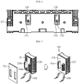
- FIG. 5 is a front view illustrating the BMS assembly 200 from which a front cover 228 is removed, according to an embodiment of the present disclosure.
- FIG. 6 is a rear view illustrating the BMS assembly 200 of FIG. 5 .
- FIG. 7 is a view illustrating elements of the temperature sensor module 230, according to an embodiment of the present disclosure.
- FIGS. 8 and 9 are views illustrating an assembly structure of the temperature sensor module 230 and a main cover 221, according to an embodiment of the present disclosure.
- the BMS assembly 200 includes the BMS circuit board 210, a BMS cover 220, a plurality of temperature sensors 230, and a plurality of sensing terminals 240.
- the BMS circuit board 210 is a component for diagnosing, estimating, and managing states of the battery cells 110.
- the temperature sensor module 230, a voltage sensing component, a current sensor, etc. may be directly or indirectly connected to the BMS circuit board 210 to transmit signals such as a temperature, a voltage, and current of the battery cell 110.
- the BMS cover 220 of the present embodiment is a structure for protecting the BMS circuit board 210 from the outside and fixing the BMS circuit board 210 not to move, and includes the main cover 221 and a front cover 228.
- the main cover 221 may support the BMS circuit board 210, may be mountably and detachably provided on the cell housing 120, may be used as a place where an electrode terminal or the like of the battery module 10 may be assembled, and may be provided as a structure having a plate shape and an area large enough to cover a side surface of the cell housing 120.
- a positive electrode terminal T1 and a negative electrode terminal T2 of the battery module 10 as well as the BMS circuit board 210, the temperature sensor module 230, and the plurality of sensing terminals 240 may be mounted on the main cover 221.
- the BMS circuit board 210 may be attached to the center of a front surface of the main cover 221, as shown in FIG. 5 .
- a bolt or hook fastening structure may be used, to fix the BMS circuit board 210 to the main cover 221.
- the front cover 228 may also be attached to the front surface of the main cover 221 on which the BMS circuit board 210 is mounted to cover a front portion of the BMS circuit board 210, thereby protecting the front portion of the BMS circuit board 210 from the outside.
- the temperature sensor module 230 is mounted on a rear surface of the main cover 221, and includes a thermistor 231, a sensor wire 232, a sensor case 233, and a spacer 234.
- the thermistor 231 may be a positive temperature coefficient (PTC) thermistor whose resistance increases as a temperature increases or a negative temperature coefficient (NTC) thermistor whose resistance decreases as a temperature increases. It is well known that the thermistor 231 functions as a sensor for converting a thermal signal into an electrical signal, and thus a detailed description of the thermistor 231 will be omitted.
- PTC positive temperature coefficient
- NTC negative temperature coefficient
- the sensor wire 232 is a portion for transmitting an electrical signal of the thermistor 231 to the BMS circuit board 210, and an end portion of the sensor wire 232 may be soldered to the BMS circuit board 210.
- the sensor case 233 is a component supporting the thermistor 231 and mountably provided on the main cover 221.
- the sensor case 233 includes a front portion including a receiving groove 233a into which the thermistor 231 may be inserted and an insertion plate 233b that may be inserted into a sensor slot 223 formed in the main cover 221, and a rear portion having a curved surface.
- a sensor slot 223 and a board connector 225 under the sensor slot 223 may be formed to pass through the main cover 221, as shown in FIGS. 8 and 9 .
- the sensor slot 223 may be sized so that, when the insertion plate 233b of the sensor case 233 is inserted into the sensor slot 223, the insertion plate 233b is tightly fitted and does not move, and the board connector 225 may be sized so that the sensor wire 232 is freely taken out and soldering on the BMS circuit board 210 is easily performed.
- the spacer 234 may be further provided on the front portion of the sensor case 233.
- the spacer 234 may be fitted as a compressed foam or pad around the insertion plate 233b and may be attached to the front portion of the sensor case 233.
- the spacer 234 may be attached to the sensor case 233 by using a double-sided adhesive tape.
- the double-sided adhesive tape may be provided on both surfaces of the spacer 234.
- the spacer 234 may be located between a front surface of the sensor case 233 and a rear surface of the main cover 221 when the insertion plate 233b of the temperature sensor module 230 is inserted into the sensor slot 223 of the main cover 221, and may absorb impact between components and may offset an interval tolerance between the temperature sensor module 230 and the battery cell 110 while the cell assembly 100 and the BMS assembly 200 are assembled.
- two temperature sensor modules 230 are mounted on a rear surface of the main cover 221, one on the left and the other on the right of the center of the main cover 221. Unlike in the present embodiment, one, or three or more temperature sensor modules 230 may be provided, or locations of the temperature sensor modules 230 may be changed.
- the temperature sensor module 230 slightly protrudes in a direction in which the sensor case 233 on the rear surface of the main cover 221 is mounted on the cell assembly 100.
- the sensor connection holes 125 are formed at positions corresponding to the temperature sensor modules 230, in a side portion of the cell housing 120 on which the main cover 221 is to be mounted, in other words, in a side portion of the tray cover 123 to be covered by the main cover 221 (see FIG. 4 ).
- the temperature sensor module 230 may be introduced into the cell housing 120 through the sensor connection hole 125 of the tray cover 123 and a curved portion of the temperature sensor module 230 may contact and surround an outer circumferential surface of the cylindrical battery cell 110.
- a thermally conductive adhesive is previously applied to a curved surface of the temperature sensor module 230, adhesion between the temperature sensor module 230 and the cylindrical battery cell 110 may be increased and thermal contact resistance may be reduced.
- the battery module 10 of the present disclosure may bring the temperature sensor module 230 into contact with the battery cell 110 without much effort in a process of assembling the BMS assembly 200 and the cell assembly 100, assembly and installation of a temperature sensor is much easier and a structure for assembling and installing the temperature sensor is simpler when compared to the battery module according to the prior art. Also, since the temperature sensor module 230 according to the present disclosure is installed as a mechanically firmly coupled structure, there is little risk that the temperature sensor module 230 is damaged or separated from the battery cell 110 even by an external force (e.g., impact or vibration).
- an external force e.g., impact or vibration
- the BMS assembly 200 further includes a plurality of sensing terminals 240.
- the plurality of sensing terminals 240 are mounted on an upper end portion of the main cover 221 and are spaced apart from one another by a certain interval, as shown in FIGS. 5 , 10, and 12 .
- One end portion of each of the sensing terminals 240 may be connected to the BMS circuit board 210 by using soldering or the like.
- 11 sensing terminals 240_1, ..., 240_11 may be arranged at almost regular intervals from a left end of the upper end portion of the main cover 221 to a right end of the upper end portion of the main cover 221, and one end portion of each of the sensing terminals 240_1, ..., 240_11 may be inserted into a rear surface of the BMS circuit board 210 and fixedly soldered from a front surface.
- the plurality of sensing terminals 240_1, ..., 240_11 may be connected in a one-to-one correspondence manner to end portions of sensing plates 130_1, ..., 130_11 extending from one end of an upper end portion of the cell housing 120 to the other end of the upper end portion of the cell housing 120. That is, the 11 sensing plates 130_1, ..., 130_11 provided in an upper portion of the cell assembly 100 may be connected in a one-to-one correspondence manner to the 11 sensing terminals 240_1, ..., 240_11 provided in an upper portion of the BMS assembly 200.
- sensing terminals 240_1, ..., 240_11 and the sensing plates 130_1, ..., 130_11 are connected to each other, for example, one end and the other end of a short conductor cable W or metal strap may be connected to the sensing terminals 240_1, ..., 240_11 and the sensing plates 130_1, ..., 130_11 by using a method such as fusion, bonding, welding, or bolting.
- the 11 sensing plates 30_1, ..., 130_11 sense a value of a node voltage of a place where the battery cells 110 are connected in series, and transmit the value of the node voltage to the BMS circuit board 210.
- the BMS circuit board 210 may control charging/discharging by monitoring voltage states of the battery cells 110 based on the voltage information.
- the 11 sensing terminals 240_1, ..., 240_11 may be components used as intermediate means for connecting the 11 sensing plates 130_1, ..., 130_11 to the BMS circuit board 210.
- the present disclosure may have a structure in which all of the sensing plates 130 are located in the upper portion of the cell assembly 100, and in order to easily connect the sensing plates 130 to the BMS circuit board 210, the sensing terminals 240 end portions of which are previously soldered to the BMS circuit board 210 are located on the upper end portion of the main cover 221.
- This assembly structure for voltage sensing may be capable of simple and compact wiring, even without using a voltage sensing component such as a conventional expensive FPCB, and may be structurally stable and thus may prevent components from being easily damaged by an external force (e.g., impact or vibration).
- a voltage sensing component such as a conventional expensive FPCB
- the battery module 10 may further include a heat sink located under the cell assembly 100.
- the heat sink is a component for indirectly cooling the battery cells 110 by passing a cooling fluid through an internal fluid path and absorbing heat from the cell tray 120 through thermal contact, and the heat sink may be located to contact a bottom surface of the cell tray 121.
- the cooling fluid flowing through the fluid path is not limited and may be any fluid as long as it easily flows through the fluid path and has excellent cooling properties.
- the cooling fluid may be water having high latent heat and capable of maximizing cooling efficiency.
- the present disclosure is not limited thereto, and as long as it flows, an anti-freezing solution, a gas refrigerant, or air may be applied.
- a battery pack according to the present disclosure may include one or more battery modules 10. Also, the battery pack according to the present disclosure may further include a pack case for accommodating the battery module 10, and various devices for controlling charging/discharging of the battery module 10, for example, a master BMS, a current sensor, and a fuse, in addition to the battery module 10.
- a pack case for accommodating the battery module 10
- various devices for controlling charging/discharging of the battery module 10 for example, a master BMS, a current sensor, and a fuse, in addition to the battery module 10.
- the battery module 10 may be applied to an electric scouter, a vehicle such as an electric vehicle or a hybrid vehicle, or an energy storage system (ESS).
- a vehicle such as an electric vehicle or a hybrid vehicle
- ESS energy storage system
Landscapes
- Chemical & Material Sciences (AREA)
- Chemical Kinetics & Catalysis (AREA)
- Electrochemistry (AREA)
- General Chemical & Material Sciences (AREA)
- Engineering & Computer Science (AREA)
- Manufacturing & Machinery (AREA)
- Microelectronics & Electronic Packaging (AREA)
- Battery Mounting, Suspending (AREA)
- Secondary Cells (AREA)
Abstract
Description
- The present disclosure relates to a battery module, and more particularly, to a battery module having a stable and compact assembly structure of an electrical/electronic component such as a temperature sensor.
- The present application claims priority to
Korean Patent Application No. 10-2020-0100768 filed on August 11, 2020 - When a battery module including a plurality of secondary batteries is used, temperature control of the battery module may be very important. In particular, the battery module may be used in a high temperature environment such as in summer, and the secondary batteries themselves may generate heat. In this case, when the plurality of batteries are densely arranged, the temperature of the secondary batteries may further increase. When the temperature is higher than an appropriate temperature, the performance of the secondary batteries may be degraded and in severe cases, there is a risk of explosion or ignition. In contrast, when the temperature of the battery module is too low, the performance of the secondary batteries included in the battery module may be degraded. Accordingly, in order to prevent performance degradation or dangerous situations of the secondary batteries or prepare for such situations, the battery module includes a temperature sensor therein to continuously monitor the temperature of the secondary batteries.
- Also, a recent battery module includes a battery management system (BMS) for monitoring and managing charging/discharging states of secondary batteries, and, as a means for sensing a voltage of each of the secondary batteries and transmitting the voltage to the BMS, a harness wire or a flexible printed circuit board (FPCB) capable of three-dimensional wiring and transmitting a number of signals.
- For example, an existing battery module has a structure in which a
connector 2, atemperature sensor 3, and a voltage sensing terminal (not shown) are mounted on a harness wire or anFPCB 1 as shown inFIG. 1 to connect eachsecondary battery cell 4, thetemperature sensor 3 or the voltage sensing terminal, and the BMS 5. - However, the harness wire has the disadvantage in that it is not easy to assemble and perform wiring in a narrow space, and the FPCB more easily performs wiring than the harness wire but has the disadvantage of low durability and low economical efficiency due to high cost.
- Also, many point out that a structure in which a thin and small FPCB or harness wire is attached to a secondary battery cell has low durability against impact and vibration and thus a sensing portion is likely to be separated or damaged.
- Accordingly, there is a demand for a battery module having a more stable and economical assembly structure of an electrical/electronic component such as a temperature sensor than an existing structure.
- The present disclosure is designed to solve the problems of the related art, and therefore the present disclosure is directed to providing a battery module having a stable and compact assembly structure of an electrical/electronic component such as a temperature sensor.
- Technical problems to be solved by the present disclosure are not limited to the above-described technical problems and one of ordinary skill in the art will understand other technical problems from the following description.
- In one aspect of the present disclosure, there is provided a battery module including a cell assembly including a plurality of battery cells and a cell housing in which the plurality of battery cells are accommodated, and a battery management system (BMS) assembly including a BMS circuit board, a BMS cover accommodating the BMS circuit board, and at least one temperature sensor module connected to the BMS circuit board and fixedly mounted on a rear surface of the BMS cover, the BMS assembly being mountably and detachably provided on a side surface of the cell housing, wherein, when the BMS assembly is mounted on the side surface of the cell housing, the temperature sensor module is configured to contact one of the plurality of battery cells.
- The battery cell may be a cylindrical battery cell, wherein a sensor connection hole is provided in the side surface of the cell housing to access the temperature sensor module, and the temperature sensor module is configured to contact the battery cell through the sensor connection hole.
- The BMS cover may include a main cover covering the side surface of the cell housing and mounted on the cell housing, wherein the BMS circuit board is attached to a front surface of the main cover, and the temperature sensor module is attached to a rear surface of the main cover.
- The BMS cover may further include a front cover covering the BMS circuit board and attached to the front surface of the main cover.
- The BMS assembly may further include a plurality of sensing terminals mounted on an upper end portion of the main cover, spaced apart from one another by a certain interval, and each having one end portion connected to the BMS circuit board.
- The cell assembly may further include sensing plates extending parallel to one another from one end of an upper end portion of the cell housing to the other end of the upper end portion of the cell housing, wherein the plurality of battery cells under the plurality of sensing plates are electrically connected to the plurality of sensing plates located at positions corresponding to the plurality of battery cells, and end portions of the plurality of sensing plates are respectively connected to the plurality of sensing terminals.
- The temperature sensor module may include a thermistor, a sensor wire extending from the thermistor and connected to the BMS circuit board, and a sensor case supporting the thermistor and forcibly fitted onto the main cover.
- The sensor case may include a front portion including a receiving groove into which the thermistor is inserted and an insertion plate that is inserted into a sensor slot formed in the main cover, and a rear portion having a curved surface.
- The temperature sensor module may further include a spacer formed of a compressed foam material and fitted around the insertion plate and disposed between the sensor case and the main cover.
- The cell housing may include a cell tray provided so that each of the plurality of battery cells is inserted and erected, and a tray cover vertically coupled to the cell tray to fix and protect the plurality of battery cells, wherein the sensor connection hole is provided in the tray cover.
- In another aspect of the present disclosure, there is also provided a battery pack including the battery module.
- According to an aspect of the present disclosure, a battery module having a stable and compact assembly structure of an electrical/electronic component such as a temperature sensor may be provided.
- The effects of the present disclosure are not limited to the effects mentioned above, and other effects not mentioned will be clearly understood by those skilled in the art from the specification and the attached drawings.
-
-
FIG. 1 is a view illustrating an assembly structure of a temperature sensor, a sensing cable, and a BMS in a battery module, according to the prior art. -
FIG. 2 is a perspective view illustrating a battery module, according to an embodiment of the present disclosure. -
FIG. 3 is a view illustrating a state in which a battery management system (BMS) assembly is detached from a cell assembly of the battery module ofFIG. 2 . -
FIG. 4 is a view illustrating the cell assembly ofFIG. 3 seen from a different direction. -
FIG. 5 is a front view illustrating the BMS assembly from which a front cover is removed, according to an embodiment of the present disclosure. -
FIG. 6 is a rear view illustrating the BMS assembly ofFIG. 5 . -
FIG. 7 is a view illustrating elements of a temperature sensor module, according to an embodiment of the present disclosure. -
FIGS. 8 and 9 are views illustrating an assembly structure of the temperature sensor module and a main cover, according to an embodiment of the present disclosure. -
FIG. 10 is a top view illustrating a BMS assembly, according to an embodiment of the present disclosure. -
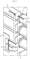
FIG. 11 is a partial cross-sectional view illustrating a battery module, according to an embodiment of the present disclosure, particularly illustrating an attachment structure between a temperature sensor module and a battery cell. -
FIG. 12 is a view illustrating a connection structure between a BMS circuit board and sensing terminals, according to an embodiment of the present disclosure. -
FIG. 13 is a view illustrating a connection structure between sensing terminals and metal plates, according to an embodiment of the present disclosure. - Hereinafter, preferred embodiments of the present disclosure will be described in detail with reference to the accompanying drawings. Prior to the description, it should be understood that the terms used in the specification and the appended claims should not be construed as limited to general and dictionary meanings, but interpreted based on the meanings and concepts corresponding to technical aspects of the present disclosure on the basis of the principle that the inventor is allowed to define terms appropriately for the best explanation.
- Therefore, the description proposed herein is just a preferable example for the purpose of illustrations only, not intended to limit the scope of the present disclosure, so it should be understood that other equivalents and modifications could be made thereto without departing from the scope of the present disclosure.
-
FIG. 2 is a perspective view illustrating a battery module, according to an embodiment of the present disclosure.FIG. 3 is a view illustrating a state in which a BMS assembly is detached from a cell assembly of the battery module ofFIG. 2 .FIG. 4 is a view illustrating the cell assembly ofFIG. 3 seen from a different direction. - Referring to
FIGS. 2 through 4 , abattery module 10 according to an embodiment of the present disclosure includes acell assembly 100 and aBMS assembly 200 mountably and detachably provided on thecell assembly 100. - As described below in detail, because the
battery module 10 according to the present disclosure has a structure in which atemperature sensor module 230 directly contacts abattery cell 110 in a process of assembling thecell assembly 100 and theBMS assembly 200, when compared to the battery module according to the prior art, a temperature sensing structure is very simple and a harness wire or an expensive flexible printed circuit board (FPCB) which was used to mount a temperature sensor does not need to be used, thereby greatly increasing economical efficiency. - The
cell assembly 100 of thebattery module 10 will be first described. Thecell assembly 100 includes a plurality ofbattery cells 110 and acell housing 120 in which the plurality ofbattery cells 110 are accommodated. - The
battery cell 110 applied to thebattery module 10 of the present embodiment is acylindrical battery cell 110 in which an electrode assembly is embedded in a metal can. Thecylindrical battery cell 110 may include a battery can having a cylindrical shape and mainly made of a lightweight conductive metal material such as aluminum, a jelly-roll type electrode assembly accommodated in the battery cell, and a cap assembly coupled to an upper portion of the battery can. The cap assembly is connected to a positive electrode tab of the electrode assembly and functions as a positive electrode terminal, and a lower end of the battery is connected to a negative electrode tab of the electrode assembly and functions as a negative electrode terminal. - The
cylindrical battery cells 110 may be inserted into thecell housing 120, and metal plates (not shown) may be spot-welded in a pre-determined pattern to upper or lower ends of thecylindrical battery cells 110 so that thecylindrical battery cells 110 are connected to one another in series and/or in parallel. - However, the scope of the present disclosure should not be construed as being limited to the
battery module 10 using thecylindrical battery cell 110. For example, thebattery module 10 according to the present disclosure may include aprismatic battery cell 110 having a rectangular battery can shape, instead of a cylindrical shape. - The cell housing 120 for fixing and protecting the
battery cells 110 may include acell tray 121 and atray cover 123. - The
cell tray 121 may have a quadrangular plate shape, may include sockets formed inside an outer edge, and may be provided so that lower end portions of thebattery cells 110 are respectively inserted into the sockets to be erected. Also, thecell tray 121 may include acatch 122 on the outer edge, and may be snap-fitted onto thetray cover 123. - The
tray cover 123 may include sockets into which upper end portions of thebattery cells 110 may be inserted, and may be provided in a box shape so that thebattery cells 110 and an upper portion of thecell tray 121 are covered. - The
tray cover 123 according to the present embodiment further includessensing plates 130 on an upper end portion thereof. Thesensing plates 130 may be spaced apart from one another by a certain interval (±Y axis direction) and may extend parallel to one another (±X axis direction) from one end of the upper end portion of thetray cover 123 to the other end of the upper end portion of thetray cover 123. - The
battery cells 110 under thesensing plates 130 may be electrically connected to thesensing plates 130 located at positions corresponding to thebattery cells 110. Referring toFIG. 4 , thebattery cells 110 may be arranged in thecell housing 120 in the Y axis direction in first through 12th columns, and thebattery cells 110 in the same column may be connected in parallel and thebattery cells 110 in adjacent columns may be connected in series. Onesensing plate 130 is located between adjacent battery cell columns and thus a total of 11sensing plates 130 are arranged. Thesensing plate 130 senses a bank voltage of a series connection portion of thebattery cells 110. - A voltage sensed by the
sensing plate 130 may be transmitted to aBMS circuit board 210 through asensing terminal 240 of theBMS assembly 200 described below. - Referring back to
FIG. 4 , thetray cover 123 further includes asensor connection hole 125. Thesensor connection hole 125 is a passage through which thetemperature sensor module 230 may access thebattery cell 110 located inside thecell housing 120, and may be formed in a side surface of thetray cover 123 on which theBMS assembly 200 is to be mounted. -
FIG. 5 is a front view illustrating theBMS assembly 200 from which afront cover 228 is removed, according to an embodiment of the present disclosure.FIG. 6 is a rear view illustrating theBMS assembly 200 ofFIG. 5 .FIG. 7 is a view illustrating elements of thetemperature sensor module 230, according to an embodiment of the present disclosure.FIGS. 8 and 9 are views illustrating an assembly structure of thetemperature sensor module 230 and amain cover 221, according to an embodiment of the present disclosure. - Referring to
FIGS. 5 through 9 , theBMS assembly 200 includes theBMS circuit board 210, aBMS cover 220, a plurality oftemperature sensors 230, and a plurality ofsensing terminals 240. - The
BMS circuit board 210 is a component for diagnosing, estimating, and managing states of thebattery cells 110. Thetemperature sensor module 230, a voltage sensing component, a current sensor, etc. may be directly or indirectly connected to theBMS circuit board 210 to transmit signals such as a temperature, a voltage, and current of thebattery cell 110. - The
BMS cover 220 of the present embodiment is a structure for protecting theBMS circuit board 210 from the outside and fixing theBMS circuit board 210 not to move, and includes themain cover 221 and afront cover 228. - The
main cover 221 may support theBMS circuit board 210, may be mountably and detachably provided on thecell housing 120, may be used as a place where an electrode terminal or the like of thebattery module 10 may be assembled, and may be provided as a structure having a plate shape and an area large enough to cover a side surface of thecell housing 120. - A positive electrode terminal T1 and a negative electrode terminal T2 of the
battery module 10 as well as theBMS circuit board 210, thetemperature sensor module 230, and the plurality ofsensing terminals 240 may be mounted on themain cover 221. - The
BMS circuit board 210 may be attached to the center of a front surface of themain cover 221, as shown inFIG. 5 . A bolt or hook fastening structure may be used, to fix theBMS circuit board 210 to themain cover 221. - The
front cover 228 may also be attached to the front surface of themain cover 221 on which theBMS circuit board 210 is mounted to cover a front portion of theBMS circuit board 210, thereby protecting the front portion of theBMS circuit board 210 from the outside. - Referring to
FIGS. 6 and 7 , thetemperature sensor module 230 is mounted on a rear surface of themain cover 221, and includes athermistor 231, asensor wire 232, asensor case 233, and aspacer 234. - The
thermistor 231 may be a positive temperature coefficient (PTC) thermistor whose resistance increases as a temperature increases or a negative temperature coefficient (NTC) thermistor whose resistance decreases as a temperature increases. It is well known that thethermistor 231 functions as a sensor for converting a thermal signal into an electrical signal, and thus a detailed description of thethermistor 231 will be omitted. - The
sensor wire 232 is a portion for transmitting an electrical signal of thethermistor 231 to theBMS circuit board 210, and an end portion of thesensor wire 232 may be soldered to theBMS circuit board 210. - The
sensor case 233 is a component supporting thethermistor 231 and mountably provided on themain cover 221. Thesensor case 233 includes a front portion including a receivinggroove 233a into which thethermistor 231 may be inserted and aninsertion plate 233b that may be inserted into asensor slot 223 formed in themain cover 221, and a rear portion having a curved surface. - To fix the
sensor case 233 and connect thethermistor 231 to theBMS circuit board 210, asensor slot 223 and aboard connector 225 under thesensor slot 223 may be formed to pass through themain cover 221, as shown inFIGS. 8 and 9 . - The
sensor slot 223 may be sized so that, when theinsertion plate 233b of thesensor case 233 is inserted into thesensor slot 223, theinsertion plate 233b is tightly fitted and does not move, and theboard connector 225 may be sized so that thesensor wire 232 is freely taken out and soldering on theBMS circuit board 210 is easily performed. - The
spacer 234 may be further provided on the front portion of thesensor case 233. Thespacer 234 may be fitted as a compressed foam or pad around theinsertion plate 233b and may be attached to the front portion of thesensor case 233. Thespacer 234 may be attached to thesensor case 233 by using a double-sided adhesive tape. The double-sided adhesive tape may be provided on both surfaces of thespacer 234. - The
spacer 234 may be located between a front surface of thesensor case 233 and a rear surface of themain cover 221 when theinsertion plate 233b of thetemperature sensor module 230 is inserted into thesensor slot 223 of themain cover 221, and may absorb impact between components and may offset an interval tolerance between thetemperature sensor module 230 and thebattery cell 110 while thecell assembly 100 and theBMS assembly 200 are assembled. - Next, an attachment structure between the
temperature sensor module 230 and thebattery cell 110 according to an embodiment of the present disclosure will be described with reference toFIGS. 10 and 11 together withFIG. 4 . - According to the present embodiment, two
temperature sensor modules 230 are mounted on a rear surface of themain cover 221, one on the left and the other on the right of the center of themain cover 221. Unlike in the present embodiment, one, or three or moretemperature sensor modules 230 may be provided, or locations of thetemperature sensor modules 230 may be changed. - When the BMS assembly is viewed from the top as shown in
FIG. 10 , thetemperature sensor module 230 slightly protrudes in a direction in which thesensor case 233 on the rear surface of themain cover 221 is mounted on thecell assembly 100. The sensor connection holes 125 are formed at positions corresponding to thetemperature sensor modules 230, in a side portion of thecell housing 120 on which themain cover 221 is to be mounted, in other words, in a side portion of thetray cover 123 to be covered by the main cover 221 (seeFIG. 4 ). - Hence, when the
main cover 221 is mounted on the side portion of thecell housing 120, as shown inFIG. 11 , thetemperature sensor module 230 may be introduced into thecell housing 120 through thesensor connection hole 125 of thetray cover 123 and a curved portion of thetemperature sensor module 230 may contact and surround an outer circumferential surface of thecylindrical battery cell 110. When a thermally conductive adhesive is previously applied to a curved surface of thetemperature sensor module 230, adhesion between thetemperature sensor module 230 and thecylindrical battery cell 110 may be increased and thermal contact resistance may be reduced. - As such, because the
battery module 10 of the present disclosure may bring thetemperature sensor module 230 into contact with thebattery cell 110 without much effort in a process of assembling theBMS assembly 200 and thecell assembly 100, assembly and installation of a temperature sensor is much easier and a structure for assembling and installing the temperature sensor is simpler when compared to the battery module according to the prior art. Also, since thetemperature sensor module 230 according to the present disclosure is installed as a mechanically firmly coupled structure, there is little risk that thetemperature sensor module 230 is damaged or separated from thebattery cell 110 even by an external force (e.g., impact or vibration). - The
BMS assembly 200 further includes a plurality ofsensing terminals 240. The plurality ofsensing terminals 240 are mounted on an upper end portion of themain cover 221 and are spaced apart from one another by a certain interval, as shown inFIGS. 5 ,10, and 12 . One end portion of each of thesensing terminals 240 may be connected to theBMS circuit board 210 by using soldering or the like. For example, 11 sensing terminals 240_1, ..., 240_11 may be arranged at almost regular intervals from a left end of the upper end portion of themain cover 221 to a right end of the upper end portion of themain cover 221, and one end portion of each of the sensing terminals 240_1, ..., 240_11 may be inserted into a rear surface of theBMS circuit board 210 and fixedly soldered from a front surface. - As shown in
FIGS. 13 , the plurality of sensing terminals 240_1, ..., 240_11 may be connected in a one-to-one correspondence manner to end portions of sensing plates 130_1, ..., 130_11 extending from one end of an upper end portion of thecell housing 120 to the other end of the upper end portion of thecell housing 120. That is, the 11 sensing plates 130_1, ..., 130_11 provided in an upper portion of thecell assembly 100 may be connected in a one-to-one correspondence manner to the 11 sensing terminals 240_1, ..., 240_11 provided in an upper portion of theBMS assembly 200. - When the sensing terminals 240_1, ..., 240_11 and the sensing plates 130_1, ..., 130_11 are connected to each other, for example, one end and the other end of a short conductor cable W or metal strap may be connected to the sensing terminals 240_1, ..., 240_11 and the sensing plates 130_1, ..., 130_11 by using a method such as fusion, bonding, welding, or bolting.
- The 11 sensing plates 30_1, ..., 130_11 sense a value of a node voltage of a place where the
battery cells 110 are connected in series, and transmit the value of the node voltage to theBMS circuit board 210. TheBMS circuit board 210 may control charging/discharging by monitoring voltage states of thebattery cells 110 based on the voltage information. In this case, the 11 sensing terminals 240_1, ..., 240_11 may be components used as intermediate means for connecting the 11 sensing plates 130_1, ..., 130_11 to theBMS circuit board 210. - For example, the present disclosure may have a structure in which all of the
sensing plates 130 are located in the upper portion of thecell assembly 100, and in order to easily connect thesensing plates 130 to theBMS circuit board 210, thesensing terminals 240 end portions of which are previously soldered to theBMS circuit board 210 are located on the upper end portion of themain cover 221. - This assembly structure for voltage sensing may be capable of simple and compact wiring, even without using a voltage sensing component such as a conventional expensive FPCB, and may be structurally stable and thus may prevent components from being easily damaged by an external force (e.g., impact or vibration).
- Although not shown, the
battery module 10 may further include a heat sink located under thecell assembly 100. The heat sink is a component for indirectly cooling thebattery cells 110 by passing a cooling fluid through an internal fluid path and absorbing heat from thecell tray 120 through thermal contact, and the heat sink may be located to contact a bottom surface of thecell tray 121. The cooling fluid flowing through the fluid path is not limited and may be any fluid as long as it easily flows through the fluid path and has excellent cooling properties. For example, the cooling fluid may be water having high latent heat and capable of maximizing cooling efficiency. However, the present disclosure is not limited thereto, and as long as it flows, an anti-freezing solution, a gas refrigerant, or air may be applied. - A battery pack according to the present disclosure may include one or
more battery modules 10. Also, the battery pack according to the present disclosure may further include a pack case for accommodating thebattery module 10, and various devices for controlling charging/discharging of thebattery module 10, for example, a master BMS, a current sensor, and a fuse, in addition to thebattery module 10. - The
battery module 10 according to the present disclosure may be applied to an electric scouter, a vehicle such as an electric vehicle or a hybrid vehicle, or an energy storage system (ESS). - The present disclosure has been described in detail. However, it should be understood that the detailed description and specific examples, while indicating preferred embodiments of the present disclosure, are given by way of illustration only, since various changes and modifications within the scope of the present disclosure will become apparent to those skilled in the art from this detailed description.
- It will be understood by one of ordinary skill in the art that when terms indicating directions such as upper, lower, left, right, front, and rear are used, these terms are only for convenience of explanation and may vary according to a position of a target object, a position of an observer, etc.
Claims (11)
- A battery module comprising: a cell assembly comprising a plurality of battery cells and a cell housing in which the plurality of battery cells are accommodated; anda battery management system (BMS) assembly comprising a BMS circuit board, a BMS cover accommodating the BMS circuit board, and at least one temperature sensor module connected to the BMS circuit board and fixedly mounted on a rear surface of the BMS cover, the BMS assembly being mountably and detachably provided on a side surface of the cell housing,wherein, when the BMS assembly is mounted on the side surface of the cell housing, the temperature sensor module is configured to contact one of the plurality of battery cells.
- The battery module of claim 1, whereinthe battery cell is a cylindrical battery cell,wherein a sensor connection hole is provided in the side surface of the cell housing to access the temperature sensor module, and the temperature sensor module is configured to contact the battery cell through the sensor connection hole.
- The battery module of claim 1, whereinthe BMS cover comprises a main cover covering the side surface of the cell housing and mounted on the cell housing,wherein the BMS circuit board is attached to a front surface of the main cover, and the temperature sensor module is attached to a rear surface of the main cover.
- The battery module of claim 3, wherein
the BMS cover comprises a front cover covering the BMS circuit board and attached to the front surface of the main cover. - The battery module of claim 3, whereinthe BMS assembly comprisesa plurality of sensing terminals mounted on an upper end portion of the main cover, spaced apart from one another, and each having one end portion connected to the BMS circuit board.
- The battery module of claim 5, whereinthe cell assembly comprises sensing plates extending parallel to one another from one end of an upper end portion of the cell housing to the other end of the upper end portion of the cell housing,wherein the plurality of battery cells under the plurality of sensing plates are electrically connected to the plurality of sensing plates located at positions corresponding to the plurality of battery cells, and end portions of the plurality of sensing plates are respectively connected to the plurality of sensing terminals.
- The battery module of claim 3, wherein
the temperature sensor module comprises:a thermistor;a sensor wire extending from the thermistor and connected to the BMS circuit board; anda sensor case supporting the thermistor and forcibly fitted onto the main cover. - The battery module of claim 7, whereinthe sensor case comprisesa front portion comprising a receiving groove into which the thermistor is inserted and an insertion plate that is inserted into a sensor slot formed in the main cover, and a rear portion having a curved surface.
- The battery module of claim 8, wherein
the temperature sensor module comprises a spacer formed of a compressed foam material and fitted around the insertion plate and disposed between the sensor case and the main cover. - The battery module of claim 2, wherein
the cell housing comprises:a cell tray provided so that each of the plurality of battery cells is inserted and erected; anda tray cover vertically coupled to the cell tray to fix and protect the plurality of battery cells,wherein the sensor connection hole is provided in the tray cover. - A battery pack comprising the battery module according to any one of claims 1 through 10.
Applications Claiming Priority (2)
| Application Number | Priority Date | Filing Date | Title |
|---|---|---|---|
| KR1020200100768A KR102866740B1 (en) | 2020-08-11 | 2020-08-11 | Battery module with imploved assembly and battery pack including the same |
| PCT/KR2021/008528 WO2022035055A1 (en) | 2020-08-11 | 2021-07-05 | Battery module having improved assemblability and battery pack comprising same |
Publications (2)
| Publication Number | Publication Date |
|---|---|
| EP4060790A1 true EP4060790A1 (en) | 2022-09-21 |
| EP4060790A4 EP4060790A4 (en) | 2024-10-16 |
Family
ID=80246782
Family Applications (1)
| Application Number | Title | Priority Date | Filing Date |
|---|---|---|---|
| EP21856062.1A Pending EP4060790A4 (en) | 2020-08-11 | 2021-07-05 | BATTERY MODULE HAVING IMPROVED ASSEMBLABLENESS AND BATTERY PACK COMPRISING SAME |
Country Status (6)
| Country | Link |
|---|---|
| US (1) | US12300792B2 (en) |
| EP (1) | EP4060790A4 (en) |
| JP (1) | JP7422877B2 (en) |
| KR (1) | KR102866740B1 (en) |
| CN (1) | CN114930610B (en) |
| WO (1) | WO2022035055A1 (en) |
Cited By (1)
| Publication number | Priority date | Publication date | Assignee | Title |
|---|---|---|---|---|
| WO2023237422A3 (en) * | 2022-06-10 | 2024-06-27 | Diehl Ako Stiftung & Co. Kg | Temperature sensor assembly, arrangement of a circuit board with a temperature sensor assembly and energy store |
Families Citing this family (6)
| Publication number | Priority date | Publication date | Assignee | Title |
|---|---|---|---|---|
| US12407031B2 (en) * | 2019-12-20 | 2025-09-02 | Lg Energy Solution, Ltd. | Sub-pack including multiple unit modules and BMS assembly, and battery pack comprising same |
| KR20230036933A (en) * | 2021-09-08 | 2023-03-15 | 주식회사 엘지에너지솔루션 | Battery production system and management method thereof |
| US12300858B2 (en) * | 2021-09-17 | 2025-05-13 | Transportation Ip Holdings, Llc | Assembly and method for battery maintenance |
| KR20230126592A (en) * | 2022-02-23 | 2023-08-30 | 주식회사 엘지에너지솔루션 | battery pack |
| CN119422270A (en) * | 2022-06-10 | 2025-02-11 | 株式会社Lg新能源 | Temperature sensing assembly and battery module including the same |
| US20240186601A1 (en) * | 2022-12-06 | 2024-06-06 | Milwaukee Electric Tool Corporation | Battery pack |
Family Cites Families (31)
| Publication number | Priority date | Publication date | Assignee | Title |
|---|---|---|---|---|
| JPH04181661A (en) | 1990-11-15 | 1992-06-29 | Seiko Epson Corp | Battery device with battery pack |
| WO2007102670A1 (en) | 2006-03-06 | 2007-09-13 | Lg Chem, Ltd. | Middle or large-sized battery module |
| KR100870457B1 (en) | 2006-05-22 | 2008-11-25 | 주식회사 엘지화학 | Battery module |
| JP4778481B2 (en) | 2007-06-07 | 2011-09-21 | 矢崎総業株式会社 | Temperature detector mounting structure |
| JP5611071B2 (en) | 2011-01-28 | 2014-10-22 | 矢崎総業株式会社 | Temperature sensor |
| JP5710375B2 (en) | 2011-05-13 | 2015-04-30 | 日立オートモティブシステムズ株式会社 | Power storage device |
| US8609276B2 (en) | 2011-06-23 | 2013-12-17 | Samsung Sdi Co., Ltd. | Battery pack |
| KR101853397B1 (en) * | 2011-09-01 | 2018-04-30 | 엘지전자 주식회사 | Battery Module |
| US9005794B2 (en) | 2011-10-21 | 2015-04-14 | Tyco Electronics Corporation | Battery connector system |
| KR101986384B1 (en) * | 2013-01-07 | 2019-06-05 | 에스케이이노베이션 주식회사 | Sensing assembly for secondary battery and Secondary Battery having the sensing assembly |
| KR102045528B1 (en) | 2013-02-14 | 2019-11-15 | 에스케이이노베이션 주식회사 | Battery module |
| KR102028172B1 (en) | 2013-06-25 | 2019-10-02 | 삼성에스디아이 주식회사 | Battery pack |
| KR102233776B1 (en) * | 2014-01-28 | 2021-03-30 | 삼성에스디아이 주식회사 | Battery module |
| ES2975858T3 (en) * | 2014-10-13 | 2024-07-16 | 24M Tech Inc | Systems and methods of charging and forming batteries in series |
| KR101722183B1 (en) | 2014-10-28 | 2017-03-31 | 주식회사 엘지화학 | Fixing structure for battery module using sensing block |
| KR101750489B1 (en) | 2014-11-24 | 2017-06-23 | 주식회사 엘지화학 | Temperature Sensor for Battery Module and Battery Module Having the Same |
| KR101839653B1 (en) | 2015-02-05 | 2018-03-16 | 주식회사 엘지화학 | Compact secondary battery module |
| KR101884722B1 (en) * | 2015-07-21 | 2018-08-02 | 주식회사 엘지화학 | Battery Module Comprising Wire-Fixing Ribs |
| JP2017059503A (en) | 2015-09-18 | 2017-03-23 | 株式会社Gsユアサ | Power storage device and manufacturing method for power storage device |
| KR102011113B1 (en) | 2015-11-05 | 2019-08-14 | 주식회사 엘지화학 | Battery module, battery pack comprising the battery module and vehicle comprising the battery pack |
| KR102032504B1 (en) * | 2015-11-06 | 2019-11-08 | 주식회사 엘지화학 | Battery Module improved impact resistance |
| KR102505615B1 (en) * | 2016-02-29 | 2023-03-06 | 삼성에스디아이 주식회사 | Battery pack |
| US10454080B2 (en) | 2016-07-13 | 2019-10-22 | Te Connectivity Corporation | Connector assembly for a battery system |
| KR20180013460A (en) | 2016-07-29 | 2018-02-07 | 박동식 | Battery apparatus |
| KR102357835B1 (en) | 2017-01-26 | 2022-02-04 | 삼성에스디아이 주식회사 | Battery pack |
| US10823786B2 (en) | 2017-07-28 | 2020-11-03 | Northstar Battery Company, Llc | Battery with internal monitoring system |
| KR102258837B1 (en) | 2017-11-06 | 2021-06-07 | 주식회사 엘지에너지솔루션 | Battery Pack enhanced assembling structure |
| EP3726989A1 (en) | 2017-12-20 | 2020-10-28 | Bayer Aktiengesellschaft | Use of fungicides for controlling mosaic scab in apples |
| KR102354401B1 (en) * | 2018-04-25 | 2022-01-20 | 주식회사 엘지에너지솔루션 | Battery module and battery pack including the same |
| KR102569157B1 (en) * | 2018-04-26 | 2023-08-22 | 에스케이온 주식회사 | Substrate for sensing and battery module comprising the same |
| KR102637979B1 (en) * | 2018-08-03 | 2024-02-19 | 에스케이온 주식회사 | Battery module |
-
2020
- 2020-08-11 KR KR1020200100768A patent/KR102866740B1/en active Active
-
2021
- 2021-07-05 CN CN202180008271.XA patent/CN114930610B/en active Active
- 2021-07-05 EP EP21856062.1A patent/EP4060790A4/en active Pending
- 2021-07-05 JP JP2022531581A patent/JP7422877B2/en active Active
- 2021-07-05 US US17/780,669 patent/US12300792B2/en active Active
- 2021-07-05 WO PCT/KR2021/008528 patent/WO2022035055A1/en not_active Ceased
Cited By (1)
| Publication number | Priority date | Publication date | Assignee | Title |
|---|---|---|---|---|
| WO2023237422A3 (en) * | 2022-06-10 | 2024-06-27 | Diehl Ako Stiftung & Co. Kg | Temperature sensor assembly, arrangement of a circuit board with a temperature sensor assembly and energy store |
Also Published As
| Publication number | Publication date |
|---|---|
| US20230010305A1 (en) | 2023-01-12 |
| US12300792B2 (en) | 2025-05-13 |
| CN114930610A (en) | 2022-08-19 |
| KR20220020156A (en) | 2022-02-18 |
| KR102866740B1 (en) | 2025-09-29 |
| EP4060790A4 (en) | 2024-10-16 |
| JP2023504802A (en) | 2023-02-07 |
| JP7422877B2 (en) | 2024-01-26 |
| CN114930610B (en) | 2025-11-07 |
| WO2022035055A1 (en) | 2022-02-17 |
Similar Documents
| Publication | Publication Date | Title |
|---|---|---|
| US12300792B2 (en) | Battery module having improved assemblability and battery pack including the same | |
| EP4007042B1 (en) | Upper part cooling-type battery pack | |
| EP2315297B1 (en) | Bus bar holder and battery pack including the same | |
| KR101097257B1 (en) | Circuit board module and battery module applying same | |
| US9246196B2 (en) | Battery unit | |
| EP2421070B1 (en) | Battery pack | |
| JP4652416B2 (en) | Secondary battery module | |
| EP3734692A1 (en) | Battery module and battery pack | |
| EP1006597B1 (en) | Battery device for loading on a mobile system | |
| US20230411800A1 (en) | Battery module having improved wire bonding connection structure between bus bar plate and icb assembly, and battery pack including the same | |
| US20150023392A1 (en) | Battery pack | |
| KR102505615B1 (en) | Battery pack | |
| EP3316338B1 (en) | Battery module with a fixing for a temperature sensitive element | |
| US20240291058A1 (en) | Cell Module Assembly and Battery Pack Comprising the Same | |
| KR20220049190A (en) | Battery module and manufacturing method thereof | |
| EP4148882A1 (en) | Battery pack | |
| KR20210131607A (en) | monitoring tool for battery module and battery module for electric vehicle having the same | |
| EP4235910B1 (en) | Battery module | |
| US20240234978A1 (en) | Battery and manufacturing method therefor, and power consuming device | |
| US20240421439A1 (en) | Rechargeable battery module | |
| EA045737B1 (en) | BATTERY MODULE MONITORING DEVICE AND BATTERY MODULE FOR ELECTRIC VEHICLE | |
| JP2025100465A (en) | Battery pack | |
| CN121282572A (en) | Switching plate structure of cylindrical battery module and cylindrical battery module | |
| JP2022079017A (en) | Conductive module | |
| KR20090026698A (en) | Battery pack |
Legal Events
| Date | Code | Title | Description |
|---|---|---|---|
| STAA | Information on the status of an ep patent application or granted ep patent |
Free format text: STATUS: THE INTERNATIONAL PUBLICATION HAS BEEN MADE |
|
| PUAI | Public reference made under article 153(3) epc to a published international application that has entered the european phase |
Free format text: ORIGINAL CODE: 0009012 |
|
| STAA | Information on the status of an ep patent application or granted ep patent |
Free format text: STATUS: REQUEST FOR EXAMINATION WAS MADE |
|
| 17P | Request for examination filed |
Effective date: 20220616 |
|
| AK | Designated contracting states |
Kind code of ref document: A1 Designated state(s): AL AT BE BG CH CY CZ DE DK EE ES FI FR GB GR HR HU IE IS IT LI LT LU LV MC MK MT NL NO PL PT RO RS SE SI SK SM TR |
|
| DAV | Request for validation of the european patent (deleted) | ||
| DAX | Request for extension of the european patent (deleted) | ||
| REG | Reference to a national code |
Ref country code: DE Ref legal event code: R079 Free format text: PREVIOUS MAIN CLASS: H01M0010480000 Ipc: H01M0050213000 |
|
| A4 | Supplementary search report drawn up and despatched |
Effective date: 20240912 |
|
| RIC1 | Information provided on ipc code assigned before grant |
Ipc: H01M 50/569 20210101ALI20240906BHEP Ipc: H01M 50/298 20210101ALI20240906BHEP Ipc: H01M 50/293 20210101ALI20240906BHEP Ipc: H01M 50/284 20210101ALI20240906BHEP Ipc: H01M 10/48 20060101ALI20240906BHEP Ipc: H01M 50/213 20210101AFI20240906BHEP |
|
| STAA | Information on the status of an ep patent application or granted ep patent |
Free format text: STATUS: EXAMINATION IS IN PROGRESS |
|
| 17Q | First examination report despatched |
Effective date: 20251124 |