EP4060712A1 - Circuit breaker - Google Patents
Circuit breaker Download PDFInfo
- Publication number
- EP4060712A1 EP4060712A1 EP20887992.4A EP20887992A EP4060712A1 EP 4060712 A1 EP4060712 A1 EP 4060712A1 EP 20887992 A EP20887992 A EP 20887992A EP 4060712 A1 EP4060712 A1 EP 4060712A1
- Authority
- EP
- European Patent Office
- Prior art keywords
- energy
- gear
- accumulating
- accumulating unit
- shaft
- Prior art date
- Legal status (The legal status is an assumption and is not a legal conclusion. Google has not performed a legal analysis and makes no representation as to the accuracy of the status listed.)
- Granted
Links
Images







Classifications
-
- H—ELECTRICITY
- H01—ELECTRIC ELEMENTS
- H01H—ELECTRIC SWITCHES; RELAYS; SELECTORS; EMERGENCY PROTECTIVE DEVICES
- H01H73/00—Protective overload circuit-breaking switches in which excess current opens the contacts by automatic release of mechanical energy stored by previous operation of a hand reset mechanism
- H01H73/02—Details
-
- H—ELECTRICITY
- H01—ELECTRIC ELEMENTS
- H01H—ELECTRIC SWITCHES; RELAYS; SELECTORS; EMERGENCY PROTECTIVE DEVICES
- H01H3/00—Mechanisms for operating contacts
- H01H3/22—Power arrangements internal to the switch for operating the driving mechanism
- H01H3/30—Power arrangements internal to the switch for operating the driving mechanism using spring motor
- H01H3/3005—Charging means
- H01H3/3015—Charging means using cam devices
-
- H—ELECTRICITY
- H01—ELECTRIC ELEMENTS
- H01H—ELECTRIC SWITCHES; RELAYS; SELECTORS; EMERGENCY PROTECTIVE DEVICES
- H01H71/00—Details of the protective switches or relays covered by groups H01H73/00 - H01H83/00
- H01H71/10—Operating or release mechanisms
-
- H—ELECTRICITY
- H01—ELECTRIC ELEMENTS
- H01H—ELECTRIC SWITCHES; RELAYS; SELECTORS; EMERGENCY PROTECTIVE DEVICES
- H01H71/00—Details of the protective switches or relays covered by groups H01H73/00 - H01H83/00
- H01H71/02—Housings; Casings; Bases; Mountings
-
- H—ELECTRICITY
- H01—ELECTRIC ELEMENTS
- H01H—ELECTRIC SWITCHES; RELAYS; SELECTORS; EMERGENCY PROTECTIVE DEVICES
- H01H2221/00—Actuators
-
- H—ELECTRICITY
- H01—ELECTRIC ELEMENTS
- H01H—ELECTRIC SWITCHES; RELAYS; SELECTORS; EMERGENCY PROTECTIVE DEVICES
- H01H2235/00—Springs
Definitions
- the present disclosure relates to a circuit breaker in which primary and secondary bevel gears are engaged with each other only when a manual energy-accumulating handle is inserted into the circuit breaker.
- a circuit breaker has a fixed contact and a movable contact that may move to a closing position for closing an alive circuit in contact with the fixed contact and to a breaking (trip) position for opening the alive circuit separated from the fixed contact, and the fixed contact and the movable contact are always in contact with each other to allow current to flow.
- the circuit breaker quickly disconnects the movable contact from the fixed contact and breaks the current, thereby protecting internal circuits and accessories of electronic devices from the overcurrent.
- the circuit breaker as described above as a device used for providing/breaking high-voltage electric power, such as in a power plant or a substation, has an actuator that may quickly block/separate contact points of the fixed and movable contacts, which are in contact with each other, from each other when necessary.
- Schemes for driving the actuator may be divided into a manual manipulation scheme, a solenoid manipulation scheme, and a closing spring manipulation scheme.
- the closing spring manipulation scheme via energy-accumulating unit among the schemes for driving the actuator charges a closing spring to be in a state in which energy thereof may be accumulated by a rotational force. Further, in order to prevent accidents when the overcurrent occurs, the closing spring that has accumulated the energy is relaxed to separate the movable contact from the fixed contact and break the current flow.
- the energy-accumulating unit is disposed in a body, so that, after opening a door of the body, the closing spring is charged manually to be in a re-closing state.
- the closing spring is charged manually to be in a re-closing state.
- a structure capable of manually charging the closing spring by inputting the rotational force from the outside of the body via manual energy-accumulating unit was developed.
- gears for example, bevel gears
- the bevel gears may be instantaneously in a non-rotatable state depending on machined and assembled states of the engaged bevel gears.
- the electric motor may also become unable to rotate and may be damaged. As the charging of the circuit breaker becomes impossible, insertion of the circuit breaker in abnormal situations such as the overcurrent becomes impossible.
- a purpose of the present disclosure is to provide a circuit breaker that, even when manual energy-accumulating unit is disposed, may prevent burnout and damage of energy-accumulating unit.
- circuit breaking unit including a fixed contact and a movable contact whose contact points are in contact with each other, and energy-accumulating unit for accumulating energy of a closing spring for controlling the contact between the fixed contact and the movable contact
- energy-accumulating unit includes main energy-accumulating unit including a cam shaft, a main output gear disposed on the cam shaft, and a main energy-accumulating casing for accommodating the main output gear therein, and auxiliary energy-accumulating unit including electromotive energy-accumulating unit linked with the cam shaft, and manual energy-accumulating unit linked with the electromotive energy-accumulating unit, wherein bevel gears inside the manual energy-accumulating unit are engaged with each other by an external force to transmit the input external force to the electromotive energy-accumulating unit to accumulate the energy of the closing spring.
- the electromotive energy-accumulating unit includes a cam shaft-linked groove connected to the cam shaft, an auxiliary output gear disposed in the cam shaft-linked groove, at least one linkage gear linked with the auxiliary output gear, and an electric motor for rotating the linkage gear.
- the linkage gear includes an electric motor gear linked with a rotation shaft of the electric motor, a primary gear linked with the electric motor gear, a primary upper gear linked with a rotation shaft of the primary gear, a secondary gear linked with the primary gear, and a tertiary gear disposed between the secondary gear and the auxiliary output gear and linked with the secondary gear and the auxiliary output gear.
- the manual energy-accumulating unit includes a secondary bevel gear linked with the linkage gear, a primary bevel gear engaged with the secondary bevel gear by the external force, a shaft that is a rotation shaft of the primary bevel gear, a spring support formed on the shaft to be spaced apart from the primary bevel gear, a rotation key protruding from a side face in a length direction of the shaft in an area of an end of the shaft, a bush formed in a cylindrical shape with only one side open as a bottom plate is formed between the primary bevel gear and the spring support, wherein a position of the bush is fixed, and a manual energy-accumulating spring disposed between the bottom plate of the bush and the spring support, wherein the manual energy-accumulating spring provides an elastic force in a direction for separating the primary bevel gear from the secondary bevel gear.
- the secondary bevel gear is linked with a rotation shaft of an integral gear linked with the primary upper gear, and a direction of the external force is a clockwise direction.
- the circuit breaker according to the present disclosure may separate the primary bevel gear and the secondary bevel gear from each other in normal times and allow the primary bevel gear and the secondary bevel gear to be engaged with each other only during the manual energy-accumulating, thereby preventing the damage and the deformation of the energy-accumulating unit.
- first element or layer when a first element or layer is referred to as being present "on” or “beneath” a second element or layer, the first element may be disposed directly on or beneath the second element or may be disposed indirectly on or beneath the second element with a third element or layer being disposed between the first and second elements or layers.
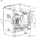
- FIGS. 1 to 3 are schematic perspective views of a circuit breaker according to the present disclosure.
- FIG. 1 is a view with a door removed
- FIG. 2 is a view showing the door
- FIG. 3 is a view with a door cover open and a manual energy-accumulating handle inserted.
- the circuit breaker includes a body 100, circuit breaking unit 200 disposed in the body 100 and in which contact points of a fixed contact and a movable contact are in contact with each other, and energy-accumulating unit 300 for accumulating energy of a closing spring that actuates the circuit breaking unit 200.
- the body 100 accommodates the circuit breaking unit 200 and the energy-accumulating unit 300 therein, and has a door 110 that may be opened and closed on at least one face thereof. Further, the door 110 may have a door cover 111 that is opened and closed such that a manual energy-accumulating handle C for driving manual energy-accumulating unit 340 to be described later is inserted thereinto. In another example, door cover 111 may be omitted.
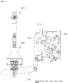
- FIG. 4 is a schematic side view of circuit breaking unit in a circuit breaker according to the present disclosure.
- the circuit breaking unit 200 is disposed in the body 100 and breaks or closes (applies current to) a circuit by a closing spring.
- Such circuit breaking unit 200 includes a drive shaft 210 that pivots in a vertical direction by the energy-accumulating unit 300, a drive link 220 that performs a vertical reciprocating motion by the drive shaft 210, a drive link 230 that pivots in the vertical direction by the vertical reciprocating motion of the drive link 220, a movable contact 240 that controls closing (electrical conduction) and breaking of the circuit breaker fixed via a fixed contact 250, and the fixed contact 250. Because of such structure, when an overcurrent or an accidental current occurs in the state in which the energy of the closing spring is accumulated, the closing spring may be released (relaxed) to separate the movable contact 240 from the fixed contact 250.
- the mechanical portion according to the present disclosure may not be limited to the above-described structure, and any structure may be applied as long as it is a structure capable of breaking the circuit by being driven by the closing spring.
- the energy-accumulating unit 300 is for accumulating the energy of the closing spring, and includes main energy-accumulating unit 310 for accumulating the energy of the closing spring, and auxiliary energy-accumulating unit 320 for accumulating the energy of the closing spring by driving the main energy-accumulating unit 310 via an electric motor 333 or manual manipulation.
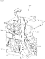
- FIG. 5 is a perspective view of the main energy-accumulating unit in a circuit breaker according to the present disclosure.
- the main energy-accumulating unit 310 includes a manual handle 311, a cam shaft 312 to which the manual handle 311 is coupled, a main output gear 313 that transmits a rotational force received via the cam shaft 312 to a cam shaft, and a main energy-accumulating casing 314 that accommodates the main output gear 313 therein. Because of such structure, in the main energy-accumulating unit 310, when the manual handle 311 pivots to one side, and the cam shaft 312 connected to the manual handle 311 also rotates. Thus, the main output gear 313 may be operated to manually accumulate the energy of the closing spring.
- the auxiliary energy-accumulating unit 320 as well as the manual handle 311 are connected, so that not only the energy-accumulating of the closing spring by the electric motor 333 of the auxiliary energy-accumulating unit 320, but also energy-accumulating of the closing spring by the manual handle 311 and energy-accumulating of the closing spring by the manual energy-accumulating handle C are possible.
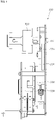
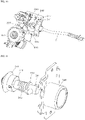
- FIG. 6 is a perspective view of auxiliary energy-accumulating unit in a circuit breaker according to the present disclosure.
- the auxiliary energy-accumulating unit 320 rotates the cam shaft 312 (in FIG. 5 ) by the electric motor 333 or the manual energy-accumulating handle C to accumulate the energy of the closing spring.
- the auxiliary energy-accumulating unit 320 includes electromotive energy-accumulating unit 330 and manual energy-accumulating unit 340.
- FIG. 7 is a perspective view of electromotive energy-accumulating unit in a circuit breaker according to the present disclosure.
- FIG. 8 is a front view of electromotive energy-accumulating unit in a circuit breaker according to the present disclosure.
- the electromotive energy-accumulating unit 330 When control power is supplied to the electric motor 333, the electromotive energy-accumulating unit 330 causes an auxiliary output gear 339 to rotate in response to the operation of the electric motor 333.
- at a position between the electric motor 333 and the auxiliary output gear 339 at least one linkage gear for linking the electric motor 333 and the auxiliary output gear 339 to each other may be disposed.
- This embodiment exemplifies a primary gear 335, a secondary gear 337, and a tertiary gear 338 as the at least one linkage gear. Further, in this embodiment, when the electric motor 333 rotates, the electric motor gear 334 rotates, and as the electric motor gear 334 rotates, the primary gear 335, the secondary gear 337, the tertiary gear 338, and the auxiliary output gear 339 sequentially rotate by being linked to each other. Further, a cam shaft-linked groove 332 connected to the auxiliary output gear 339 is assembled with the cam shaft 312 to enable a closing spring charging operation.
- FIG. 9 is a schematic perspective view of an auxiliary energy-accumulating unit in a circuit breaker according to the present disclosure
- FIG. 10 is a schematic perspective view of an auxiliary energy-accumulating unit into which a manual energy-accumulating handle is inserted in a circuit breaker according to the present disclosure
- FIG. 11 is a schematic exploded perspective view of manual energy-accumulating unit in a circuit breaker according to the present disclosure.
- the manual energy-accumulating unit 340 rotates the auxiliary output gear 339 manually from the outside, so that the energy of the closing spring is accumulated. More specifically, referring to FIG. 9 and FIG. 10 , when the manual energy-accumulating handle C pivots in one direction, for example, in a clockwise direction, the primary bevel gear 341 also rotates in the clockwise direction. Further, the secondary bevel gear 347 linked with the primary bevel gear 341 also rotates. When the secondary bevel gear 347 rotates, a gear 348 integral with the secondary bevel gear 347 also rotates to drive a primary upper gear 336. Accordingly, the secondary gear 337, the tertiary gear 338, and the auxiliary output gear 339 rotate to perform the charging operation of the mechanism.
- the manual energy-accumulating unit 340 includes the primary bevel gear 341 engaged with the secondary bevel gear 347 by compression, a shaft 342 that is a rotation shaft of the primary bevel gear 341, a spring support 343 disposed on the shaft 342 so as to be spaced apart from the primary bevel gear 341, a rotation key 344 protruding from a side face in a length direction of the shaft 342 at an end of the shaft 342, a bush 346 having a cylindrical shape with only one side open as a bottom plate is formed, wherein the bottom plate is located between the primary bevel gear 341 and the spring support 343 and fixed to an auxiliary energy-accumulating casing 331, and a manual energy-accumulating spring 345 disposed between the bottom plate of the bush 346 and the spring support 343.
- the primary bevel gear 341 is engaged with the secondary bevel gear 347 to rotate the secondary bevel gear 347.
- the present disclosure makes the primary bevel gear 341 to be spaced apart from the secondary bevel gear 347 when the manual energy-accumulating unit 340 is not in operation, and makes the primary bevel gear 341 to be engaged with the secondary bevel gear 347 only when the manual energy-accumulating unit 340 is in operation.
- the shaft 342 is formed in a shape extending from the rotation shaft of the primary bevel gear 341. The other side of such shaft 342 is exposed to the outside of the auxiliary energy-accumulating casing 331 through the bush 346, which will be described later, and the shaft 342 rotates in engagement with the manual energy-accumulating handle C to rotate the primary bevel gear 341 disposed on one side thereof.
- the spring support 343 is disposed on the shaft 342 to support one side of the manual energy-accumulating spring 345. Further, spring support 343 is disposed on the shaft 342 to be spaced apart from the primary bevel gear 341.
- This embodiment illustrates an O-ring as the spring support 343.
- the present disclosure may not be limited thereto, and the spring support 343 may be formed to extend and protrude circularly from the shaft 342 without being coupled to the shaft 342 in the form of the O-ring. Further, the present disclosure may support said one side of the manual energy-accumulating spring 345 by protruding a protrusion from a side face of the shaft 342 like the rotation key 344 instead of the O-ring-shaped spring support 343. That is, the present disclosure is not limited in the shape and the structure of the spring support 343 as long as it is able to support said one side of the manual energy-accumulating spring 345.
- the rotation key 344 When the manual energy-accumulating unit 340 is operated, the rotation key 344 is coupled to the manual energy-accumulating handle C to rotate the shaft 342. That is, the rotation key 344 serves as a protrusion for rotating the shaft 342, and is disposed on the other side of the shaft 342 to protrude in a direction intersecting the length direction of the shaft 342. Further, the rotation key 344 is disposed on the other side of the shaft 342 to be disposed on the other side of the spring support 343, that is, the primary bevel gear 341, the spring support 343, and the rotation key 344 are disposed on the shaft 342 in the order.
- the bush 346 supports the other side of the manual energy-accumulating spring 345 and supports the manual energy-accumulating handle C, which is inserted thereinto when the manual energy-accumulating unit 340 is operated.
- the bush 346 has the cylindrical shape having the hollow defined therein with only one side open as the bottom plate is formed on one side as described above, and a hole is defined in the bottom plate to allow the shaft 342 to extend therethrough. Further, an inner face of the bottom plate of said one side supports the other side of the manual energy-accumulating spring 345, and the aforementioned spring support 343 supports said one side of the manual energy-accumulating spring 345.
- the bush 346 is fixed by being coupled to the auxiliary energy-accumulating casing 331, so that the shaft 342 equipped with the primary bevel gear 341, the spring support 343, and the rotation key 344 may reciprocate through the fixed bush 346.
- the spring support 343 is exposed to the outside of the auxiliary energy-accumulating casing 331 through the bush 346 and a bottom face of the bush 346 is located inside the auxiliary energy-accumulating casing 331, the shaft 342 equipped with the primary bevel gear 341, the spring support 343, and the rotation key 344 does not deviate from the fixed bush 346.
- the manual energy-accumulating spring 345 is positioned between the bottom plate of the fixed bush 346 and the spring support 343 disposed on the reciprocating shaft 342. Further, accordingly, the spring support 343 is pushed from the bush 346, so that the shaft 342 equipped with the spring support 343 is also pushed out of the auxiliary energy-accumulating casing 331. Therefore, the primary bevel gear 341 disposed on one side of the shaft 342 is also pushed out together with the shaft 342 to be separated from the secondary bevel gear 347. In another example, when the manual energy-accumulating handle C is inserted into the bush 346, is coupled with the other side of the shaft 342 and the rotation key 344, and then applies a pressure to the shaft 342, the manual energy-accumulating spring 345 is compressed.
- the spring support 343 is moved into the auxiliary energy-accumulating casing 331, and accordingly, the shaft 342 coupled with the spring support 343 and the primary bevel gear 341 disposed on said one side of the shaft 342 are also moved together and engaged with the secondary bevel gear 347.
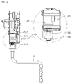
- FIG. 12 is a perspective view of manual energy-accumulating unit before a shaft is compressed in a circuit breaker according to the present disclosure
- FIG. 13 is a plan view of auxiliary energy-accumulating unit in a state before a manual energy-accumulating handle is inserted to compress a shaft in a circuit breaker according to the present disclosure.
- the manual energy-accumulating spring 345 presses the spring support 343 to increase a gap between the bush 346 and the spring support 343.
- the bush 346 is fixed in position, so that only the spring support 343 is moved away from the bush 346, and the shaft 342 coupled with the spring support 343 and the primary bevel gear 341 disposed on said one side of the shaft 342 are also moved following the spring support 343.
- the primary bevel gear 341 may be separated from the secondary bevel gear 347, and the secondary bevel gear 347 may rotate without the influence of the primary bevel gear 341 when the electromotive energy-accumulating unit 300 is operated. That is, the present disclosure makes a distance between the primary bevel gear 341 and the bottom plate of the bush 346 the same as a distance between the secondary bevel gear 347 and the bottom plate of the bush 346 when the manual energy-accumulating spring 345 is compressed, so that the primary bevel gear 341 and the secondary bevel gear 347 are engaged with each other only when the manual energy-accumulating spring is compressed.
- FIG. 14 is a perspective view of manual energy-accumulating unit after a shaft is compressed in a circuit breaker according to the present disclosure
- FIG. 15 is a plan view of auxiliary energy-accumulating unit in a state in which a manual energy-accumulating handle is inserted and compresses a shaft in a circuit breaker according to the present disclosure.
- the primary bevel gear 341 is engaged with the secondary bevel gear 347, and the secondary bevel gear 347 is also rotated by the primary bevel gear 341 that rotates in response to the pivoting of the manual energy-accumulating handle C, thereby accumulating the energy of the closing spring.
- the present disclosure separates the secondary bevel gear and the primary bevel gear from each other in normal times, and allows the secondary bevel gear and the primary bevel gear to be engaged with each other only during the manual energy-accumulating, thereby preventing the damage and the deformation of the energy-accumulating unit.
Landscapes
- Driving Mechanisms And Operating Circuits Of Arc-Extinguishing High-Tension Switches (AREA)
- Breakers (AREA)
Abstract
Description
- The present disclosure relates to a circuit breaker in which primary and secondary bevel gears are engaged with each other only when a manual energy-accumulating handle is inserted into the circuit breaker.
- In general, a circuit breaker has a fixed contact and a movable contact that may move to a closing position for closing an alive circuit in contact with the fixed contact and to a breaking (trip) position for opening the alive circuit separated from the fixed contact, and the fixed contact and the movable contact are always in contact with each other to allow current to flow. When overcurrent occurs due to a failure at a predefined position on a line, the circuit breaker quickly disconnects the movable contact from the fixed contact and breaks the current, thereby protecting internal circuits and accessories of electronic devices from the overcurrent. The circuit breaker as described above as a device used for providing/breaking high-voltage electric power, such as in a power plant or a substation, has an actuator that may quickly block/separate contact points of the fixed and movable contacts, which are in contact with each other, from each other when necessary. Schemes for driving the actuator may be divided into a manual manipulation scheme, a solenoid manipulation scheme, and a closing spring manipulation scheme. In this regard, the closing spring manipulation scheme via energy-accumulating unit among the schemes for driving the actuator charges a closing spring to be in a state in which energy thereof may be accumulated by a rotational force. Further, in order to prevent accidents when the overcurrent occurs, the closing spring that has accumulated the energy is relaxed to separate the movable contact from the fixed contact and break the current flow.
- However, in the existing circuit breaker, the energy-accumulating unit is disposed in a body, so that, after opening a door of the body, the closing spring is charged manually to be in a re-closing state. In this case, there is a problem that an operator is exposed to high voltage. In order to solve such problem, a structure capable of manually charging the closing spring by inputting the rotational force from the outside of the body via manual energy-accumulating unit was developed.
- However, in order to input the rotational force from the outside, gears, for example, bevel gears, of the manual energy-accumulating unit are always engaged with each other inside the energy-accumulating unit. In this case, even when the manual energy-accumulating unit is not used, when an electric motor of the energy-accumulating unit is operated, the bevel gears may be instantaneously in a non-rotatable state depending on machined and assembled states of the engaged bevel gears. Further, when the bevel gears become in the non-rotatable state as described above, the electric motor may also become unable to rotate and may be damaged. As the charging of the circuit breaker becomes impossible, insertion of the circuit breaker in abnormal situations such as the overcurrent becomes impossible.
- A purpose of the present disclosure is to provide a circuit breaker that, even when manual energy-accumulating unit is disposed, may prevent burnout and damage of energy-accumulating unit.
- Purposes of the present disclosure are not limited to the above-mentioned purpose. Other purposes and advantages of the present disclosure that are not mentioned above may be understood based on following descriptions, and will be more clearly understood with reference to embodiments of the present disclosure. Further, it will be readily apparent that the purposes and advantages of the present disclosure may be realized using unit and combinations thereof indicated in the Claims.
- One aspect of the present disclosure provides a circuit breaker including circuit breaking unit including a fixed contact and a movable contact whose contact points are in contact with each other, and energy-accumulating unit for accumulating energy of a closing spring for controlling the contact between the fixed contact and the movable contact, wherein the energy-accumulating unit includes main energy-accumulating unit including a cam shaft, a main output gear disposed on the cam shaft, and a main energy-accumulating casing for accommodating the main output gear therein, and auxiliary energy-accumulating unit including electromotive energy-accumulating unit linked with the cam shaft, and manual energy-accumulating unit linked with the electromotive energy-accumulating unit, wherein bevel gears inside the manual energy-accumulating unit are engaged with each other by an external force to transmit the input external force to the electromotive energy-accumulating unit to accumulate the energy of the closing spring.
- In one implementation of the circuit breaker, the electromotive energy-accumulating unit includes a cam shaft-linked groove connected to the cam shaft, an auxiliary output gear disposed in the cam shaft-linked groove, at least one linkage gear linked with the auxiliary output gear, and an electric motor for rotating the linkage gear.
- In one implementation of the circuit breaker, the linkage gear includes an electric motor gear linked with a rotation shaft of the electric motor, a primary gear linked with the electric motor gear, a primary upper gear linked with a rotation shaft of the primary gear, a secondary gear linked with the primary gear, and a tertiary gear disposed between the secondary gear and the auxiliary output gear and linked with the secondary gear and the auxiliary output gear.
- In one implementation of the circuit breaker, the manual energy-accumulating unit includes a secondary bevel gear linked with the linkage gear, a primary bevel gear engaged with the secondary bevel gear by the external force, a shaft that is a rotation shaft of the primary bevel gear, a spring support formed on the shaft to be spaced apart from the primary bevel gear, a rotation key protruding from a side face in a length direction of the shaft in an area of an end of the shaft, a bush formed in a cylindrical shape with only one side open as a bottom plate is formed between the primary bevel gear and the spring support, wherein a position of the bush is fixed, and a manual energy-accumulating spring disposed between the bottom plate of the bush and the spring support, wherein the manual energy-accumulating spring provides an elastic force in a direction for separating the primary bevel gear from the secondary bevel gear.
- In one implementation of the circuit breaker, the secondary bevel gear is linked with a rotation shaft of an integral gear linked with the primary upper gear, and a direction of the external force is a clockwise direction.
- The circuit breaker according to the present disclosure may separate the primary bevel gear and the secondary bevel gear from each other in normal times and allow the primary bevel gear and the secondary bevel gear to be engaged with each other only during the manual energy-accumulating, thereby preventing the damage and the deformation of the energy-accumulating unit.
- In addition to the above-described effects, the specific effects of the present disclosure will be described together while describing specific details for carrying out the invention below.
-
-
FIGS. 1 to 3 are schematic perspective views of a circuit breaker according to the present disclosure. -
FIG. 4 is a schematic side view of circuit breaking unit in a circuit breaker according to the present disclosure. -
FIG. 5 is a perspective view of main energy-accumulating unit in a circuit breaker according to the present disclosure. -
FIG. 6 is a perspective view of auxiliary energy-accumulating unit in a circuit breaker according to the present disclosure. -
FIG. 7 is a perspective view of electromotive energy-accumulating unit in a circuit breaker according to the present disclosure. -
FIG. 8 is a front view of electromotive energy-accumulating unit in a circuit breaker according to the present disclosure. -
FIG. 9 is a schematic perspective view of auxiliary energy-accumulating unit in a circuit breaker according to the present disclosure. -
FIG. 10 is a schematic perspective view of auxiliary energy-accumulating unit into which a manual energy-accumulating handle is inserted in a circuit breaker according to the present disclosure. -
FIG. 11 is a schematic exploded perspective view of manual energy-accumulating unit in a circuit breaker according to the present disclosure. -
FIG. 12 is a perspective view of manual energy-accumulating unit before a shaft is compressed in a circuit breaker according to the present disclosure. -
FIG. 13 is a plan view of auxiliary energy-accumulating unit in a state before a manual energy-accumulating handle is inserted to compress a shaft in a circuit breaker according to the present disclosure. -
FIG. 14 is a perspective view of manual energy-accumulating unit after a shaft is compressed in a circuit breaker according to the present disclosure. -
FIG. 15 is a plan view of auxiliary energy-accumulating unit in a state in which a manual energy-accumulating handle is inserted and compresses a shaft in a circuit breaker according to the present disclosure. - The above objects, features and advantages will be described in detail later with reference to the accompanying drawings. Accordingly, a person with ordinary knowledge in the technical field to which the present disclosure belongs will be able to easily implement the technical idea of the present disclosure. In describing the present disclosure, when it is determined that a detailed description of a known component related to the present disclosure may unnecessarily obscure gist the present disclosure, the detailed description is omitted. Hereinafter, a preferred embodiment according to the present disclosure will be described in detail with reference to the accompanying drawings. In the drawings, the same reference numerals are used to indicate the same or similar elements.
- In addition, it will also be understood that when a first element or layer is referred to as being present "on" or "beneath" a second element or layer, the first element may be disposed directly on or beneath the second element or may be disposed indirectly on or beneath the second element with a third element or layer being disposed between the first and second elements or layers.
- Hereinafter, a circuit breaker according to an embodiment of the present disclosure will be described.
-
FIGS. 1 to 3 are schematic perspective views of a circuit breaker according to the present disclosure.FIG. 1 is a view with a door removed,FIG. 2 is a view showing the door, andFIG. 3 is a view with a door cover open and a manual energy-accumulating handle inserted. - As shown in
FIGS. 1 to 3 , the circuit breaker according to the present disclosure includes abody 100,circuit breaking unit 200 disposed in thebody 100 and in which contact points of a fixed contact and a movable contact are in contact with each other, and energy-accumulatingunit 300 for accumulating energy of a closing spring that actuates thecircuit breaking unit 200. - The
body 100 accommodates thecircuit breaking unit 200 and the energy-accumulatingunit 300 therein, and has adoor 110 that may be opened and closed on at least one face thereof. Further, thedoor 110 may have adoor cover 111 that is opened and closed such that a manual energy-accumulating handle C for driving manual energy-accumulatingunit 340 to be described later is inserted thereinto. In another example,door cover 111 may be omitted. -
FIG. 4 is a schematic side view of circuit breaking unit in a circuit breaker according to the present disclosure. - The circuit breaking
unit 200 is disposed in thebody 100 and breaks or closes (applies current to) a circuit by a closing spring. Suchcircuit breaking unit 200 includes adrive shaft 210 that pivots in a vertical direction by the energy-accumulatingunit 300, adrive link 220 that performs a vertical reciprocating motion by thedrive shaft 210, adrive link 230 that pivots in the vertical direction by the vertical reciprocating motion of thedrive link 220, amovable contact 240 that controls closing (electrical conduction) and breaking of the circuit breaker fixed via afixed contact 250, and thefixed contact 250. Because of such structure, when an overcurrent or an accidental current occurs in the state in which the energy of the closing spring is accumulated, the closing spring may be released (relaxed) to separate themovable contact 240 from thefixed contact 250. - In another example, the mechanical portion according to the present disclosure may not be limited to the above-described structure, and any structure may be applied as long as it is a structure capable of breaking the circuit by being driven by the closing spring.
- The energy-accumulating
unit 300 is for accumulating the energy of the closing spring, and includes main energy-accumulatingunit 310 for accumulating the energy of the closing spring, and auxiliary energy-accumulatingunit 320 for accumulating the energy of the closing spring by driving the main energy-accumulatingunit 310 via anelectric motor 333 or manual manipulation. -
FIG. 5 is a perspective view of the main energy-accumulating unit in a circuit breaker according to the present disclosure. - The main energy-accumulating
unit 310 includes amanual handle 311, acam shaft 312 to which themanual handle 311 is coupled, amain output gear 313 that transmits a rotational force received via thecam shaft 312 to a cam shaft, and a main energy-accumulatingcasing 314 that accommodates themain output gear 313 therein. Because of such structure, in the main energy-accumulatingunit 310, when themanual handle 311 pivots to one side, and thecam shaft 312 connected to themanual handle 311 also rotates. Thus, themain output gear 313 may be operated to manually accumulate the energy of the closing spring. That is, in the main energy-accumulatingunit 310, the auxiliary energy-accumulatingunit 320 as well as themanual handle 311 are connected, so that not only the energy-accumulating of the closing spring by theelectric motor 333 of the auxiliary energy-accumulatingunit 320, but also energy-accumulating of the closing spring by themanual handle 311 and energy-accumulating of the closing spring by the manual energy-accumulating handle C are possible. -
FIG. 6 is a perspective view of auxiliary energy-accumulating unit in a circuit breaker according to the present disclosure. - The auxiliary energy-accumulating
unit 320 rotates the cam shaft 312 (inFIG. 5 ) by theelectric motor 333 or the manual energy-accumulating handle C to accumulate the energy of the closing spring. For this purpose, the auxiliary energy-accumulatingunit 320 includes electromotive energy-accumulatingunit 330 and manual energy-accumulatingunit 340. -
FIG. 7 is a perspective view of electromotive energy-accumulating unit in a circuit breaker according to the present disclosure.FIG. 8 is a front view of electromotive energy-accumulating unit in a circuit breaker according to the present disclosure. - When control power is supplied to the
electric motor 333, the electromotive energy-accumulatingunit 330 causes anauxiliary output gear 339 to rotate in response to the operation of theelectric motor 333. In this regard, at a position between theelectric motor 333 and theauxiliary output gear 339, at least one linkage gear for linking theelectric motor 333 and theauxiliary output gear 339 to each other may be disposed. - This embodiment exemplifies a
primary gear 335, asecondary gear 337, and atertiary gear 338 as the at least one linkage gear. Further, in this embodiment, when theelectric motor 333 rotates, theelectric motor gear 334 rotates, and as theelectric motor gear 334 rotates, theprimary gear 335, thesecondary gear 337, thetertiary gear 338, and theauxiliary output gear 339 sequentially rotate by being linked to each other. Further, a cam shaft-linkedgroove 332 connected to theauxiliary output gear 339 is assembled with thecam shaft 312 to enable a closing spring charging operation. -
FIG. 9 is a schematic perspective view of an auxiliary energy-accumulating unit in a circuit breaker according to the present disclosure, andFIG. 10 is a schematic perspective view of an auxiliary energy-accumulating unit into which a manual energy-accumulating handle is inserted in a circuit breaker according to the present disclosure.FIG. 11 is a schematic exploded perspective view of manual energy-accumulating unit in a circuit breaker according to the present disclosure. - The manual energy-accumulating
unit 340 rotates theauxiliary output gear 339 manually from the outside, so that the energy of the closing spring is accumulated. More specifically, referring toFIG. 9 andFIG. 10 , when the manual energy-accumulating handle C pivots in one direction, for example, in a clockwise direction, theprimary bevel gear 341 also rotates in the clockwise direction. Further, thesecondary bevel gear 347 linked with theprimary bevel gear 341 also rotates. When thesecondary bevel gear 347 rotates, agear 348 integral with thesecondary bevel gear 347 also rotates to drive a primaryupper gear 336. Accordingly, thesecondary gear 337, thetertiary gear 338, and theauxiliary output gear 339 rotate to perform the charging operation of the mechanism. - As shown in
FIG. 11 , the manual energy-accumulatingunit 340 includes theprimary bevel gear 341 engaged with thesecondary bevel gear 347 by compression, ashaft 342 that is a rotation shaft of theprimary bevel gear 341, aspring support 343 disposed on theshaft 342 so as to be spaced apart from theprimary bevel gear 341, arotation key 344 protruding from a side face in a length direction of theshaft 342 at an end of theshaft 342, abush 346 having a cylindrical shape with only one side open as a bottom plate is formed, wherein the bottom plate is located between theprimary bevel gear 341 and thespring support 343 and fixed to an auxiliary energy-accumulatingcasing 331, and a manual energy-accumulatingspring 345 disposed between the bottom plate of thebush 346 and thespring support 343. - The
primary bevel gear 341 is engaged with thesecondary bevel gear 347 to rotate thesecondary bevel gear 347. In this regard, the present disclosure makes theprimary bevel gear 341 to be spaced apart from thesecondary bevel gear 347 when the manual energy-accumulatingunit 340 is not in operation, and makes theprimary bevel gear 341 to be engaged with thesecondary bevel gear 347 only when the manual energy-accumulatingunit 340 is in operation. - The
shaft 342 is formed in a shape extending from the rotation shaft of theprimary bevel gear 341. The other side ofsuch shaft 342 is exposed to the outside of the auxiliary energy-accumulatingcasing 331 through thebush 346, which will be described later, and theshaft 342 rotates in engagement with the manual energy-accumulating handle C to rotate theprimary bevel gear 341 disposed on one side thereof. - The
spring support 343 is disposed on theshaft 342 to support one side of the manual energy-accumulatingspring 345. Further,spring support 343 is disposed on theshaft 342 to be spaced apart from theprimary bevel gear 341. This embodiment illustrates an O-ring as thespring support 343. However, the present disclosure may not be limited thereto, and thespring support 343 may be formed to extend and protrude circularly from theshaft 342 without being coupled to theshaft 342 in the form of the O-ring. Further, the present disclosure may support said one side of the manual energy-accumulatingspring 345 by protruding a protrusion from a side face of theshaft 342 like therotation key 344 instead of the O-ring-shapedspring support 343. That is, the present disclosure is not limited in the shape and the structure of thespring support 343 as long as it is able to support said one side of the manual energy-accumulatingspring 345. - When the manual energy-accumulating
unit 340 is operated, therotation key 344 is coupled to the manual energy-accumulating handle C to rotate theshaft 342. That is, therotation key 344 serves as a protrusion for rotating theshaft 342, and is disposed on the other side of theshaft 342 to protrude in a direction intersecting the length direction of theshaft 342. Further, therotation key 344 is disposed on the other side of theshaft 342 to be disposed on the other side of thespring support 343, that is, theprimary bevel gear 341, thespring support 343, and therotation key 344 are disposed on theshaft 342 in the order. - The
bush 346 supports the other side of the manual energy-accumulatingspring 345 and supports the manual energy-accumulating handle C, which is inserted thereinto when the manual energy-accumulatingunit 340 is operated. To this end, thebush 346 has the cylindrical shape having the hollow defined therein with only one side open as the bottom plate is formed on one side as described above, and a hole is defined in the bottom plate to allow theshaft 342 to extend therethrough. Further, an inner face of the bottom plate of said one side supports the other side of the manual energy-accumulatingspring 345, and theaforementioned spring support 343 supports said one side of the manual energy-accumulatingspring 345. In this regard, thebush 346 is fixed by being coupled to the auxiliary energy-accumulatingcasing 331, so that theshaft 342 equipped with theprimary bevel gear 341, thespring support 343, and therotation key 344 may reciprocate through the fixedbush 346. In another example, because thespring support 343 is exposed to the outside of the auxiliary energy-accumulatingcasing 331 through thebush 346 and a bottom face of thebush 346 is located inside the auxiliary energy-accumulatingcasing 331, theshaft 342 equipped with theprimary bevel gear 341, thespring support 343, and therotation key 344 does not deviate from the fixedbush 346. - The manual energy-accumulating
spring 345 is positioned between the bottom plate of the fixedbush 346 and thespring support 343 disposed on thereciprocating shaft 342. Further, accordingly, thespring support 343 is pushed from thebush 346, so that theshaft 342 equipped with thespring support 343 is also pushed out of the auxiliary energy-accumulatingcasing 331. Therefore, theprimary bevel gear 341 disposed on one side of theshaft 342 is also pushed out together with theshaft 342 to be separated from thesecondary bevel gear 347. In another example, when the manual energy-accumulating handle C is inserted into thebush 346, is coupled with the other side of theshaft 342 and therotation key 344, and then applies a pressure to theshaft 342, the manual energy-accumulatingspring 345 is compressed. Further, when the manual energy-accumulatingspring 345 is compressed, thespring support 343 is moved into the auxiliary energy-accumulatingcasing 331, and accordingly, theshaft 342 coupled with thespring support 343 and theprimary bevel gear 341 disposed on said one side of theshaft 342 are also moved together and engaged with thesecondary bevel gear 347. -
FIG. 12 is a perspective view of manual energy-accumulating unit before a shaft is compressed in a circuit breaker according to the present disclosure, andFIG. 13 is a plan view of auxiliary energy-accumulating unit in a state before a manual energy-accumulating handle is inserted to compress a shaft in a circuit breaker according to the present disclosure. - Referring to
FIG. 12 andFIG. 13 , before the manual energy-accumulatingunit 340 is operated, that is, before the manual energy-accumulating handle C presses theshaft 342, the manual energy-accumulatingspring 345 presses thespring support 343 to increase a gap between thebush 346 and thespring support 343. In this regard, thebush 346 is fixed in position, so that only thespring support 343 is moved away from thebush 346, and theshaft 342 coupled with thespring support 343 and theprimary bevel gear 341 disposed on said one side of theshaft 342 are also moved following thespring support 343. Further, accordingly, theprimary bevel gear 341 may be separated from thesecondary bevel gear 347, and thesecondary bevel gear 347 may rotate without the influence of theprimary bevel gear 341 when the electromotive energy-accumulatingunit 300 is operated. That is, the present disclosure makes a distance between theprimary bevel gear 341 and the bottom plate of thebush 346 the same as a distance between thesecondary bevel gear 347 and the bottom plate of thebush 346 when the manual energy-accumulatingspring 345 is compressed, so that theprimary bevel gear 341 and thesecondary bevel gear 347 are engaged with each other only when the manual energy-accumulating spring is compressed. -
FIG. 14 is a perspective view of manual energy-accumulating unit after a shaft is compressed in a circuit breaker according to the present disclosure, andFIG. 15 is a plan view of auxiliary energy-accumulating unit in a state in which a manual energy-accumulating handle is inserted and compresses a shaft in a circuit breaker according to the present disclosure. - Referring to
FIG. 14 andFIG. 15 , when the manual energy-accumulatingunit 340 is operated, that is, the manual energy-accumulating handle C is inserted into the manual energy-accumulatingunit 340 and compresses theshaft 342, thespring support 343 is compressed by the manual energy-accumulating handle C to compress the manual energy-accumulatingspring 345. In this case, because the position of thebush 346 is fixed, only thespring support 343 comes close to thebush 346, and theshaft 342 coupled with thespring support 343 and theprimary bevel gear 341 disposed on said one side of theshaft 342 are moved along thespring support 343. Accordingly, theprimary bevel gear 341 is engaged with thesecondary bevel gear 347, and thesecondary bevel gear 347 is also rotated by theprimary bevel gear 341 that rotates in response to the pivoting of the manual energy-accumulating handle C, thereby accumulating the energy of the closing spring. - As described above, the present disclosure separates the secondary bevel gear and the primary bevel gear from each other in normal times, and allows the secondary bevel gear and the primary bevel gear to be engaged with each other only during the manual energy-accumulating, thereby preventing the damage and the deformation of the energy-accumulating unit.
- As described above, the present disclosure has been described with reference to the illustrated drawings, but the present disclosure is not limited by the embodiment and the drawings disclosed in the present disclosure, and it is apparent that various modifications may be made by an ordinary person skilled in the art within the scope of the technical idea of the present disclosure. In addition, even when the effect based on the component of the present disclosure has not been explicitly described while describing the embodiment of the present disclosure, it goes without saying that the effect predictable by the corresponding component should also be recognized.
Claims (6)
- A circuit breaker comprising:circuit breaking unit including a fixed contact and a movable contact whose contact points are in contact with each other; andenergy-accumulating unit for accumulating energy of a closing spring for controlling the contact between the fixed contact and the movable contact,wherein the energy-accumulating unit includes:main energy-accumulating unit including a cam shaft, a main output gear disposed on the cam shaft, and a main energy-accumulating casing for accommodating the main output gear; andauxiliary energy-accumulating unit including electromotive energy-accumulating unit linked with the cam shaft, and manual energy-accumulating unit linked with the electromotive energy-accumulating unit, wherein bevel gears inside the manual energy-accumulating unit are engaged with each other by an external force to transmit the input external force to the electromotive energy-accumulating unit to accumulate the energy of the closing spring.
- The circuit breaker of claim 1, wherein the electromotive energy-accumulating unit includes:a cam shaft-linked groove connected to the cam shaft;an auxiliary output gear disposed in the cam shaft-linked groove;at least one linkage gear linked with the auxiliary output gear; andan electric motor for rotating the linkage gear.
- The circuit breaker of claim 2, wherein the linkage gear includes:an electric motor gear linked with a rotation shaft of the electric motor;a primary gear linked with the electric motor gear;a primary upper gear linked with a rotation shaft of the primary gear;a secondary gear linked with the primary gear; anda tertiary gear disposed between the secondary gear and the auxiliary output gear and linked with the secondary gear and the auxiliary output gear.
- The circuit breaker of claim 3, wherein the manual energy-accumulating unit includes:a secondary bevel gear linked with the linkage gear;a primary bevel gear engaged with the secondary bevel gear by the external force;a shaft that is a rotation shaft of the primary bevel gear;a spring support formed on the shaft to be spaced apart from the primary bevel gear;a rotation key protruding from a side face in a length direction of the shaft in an area of an end of the shaft;a bush formed in a cylindrical shape with only one side open as a bottom plate is formed between the primary bevel gear and the spring support, wherein a position of the bush is fixed; anda manual energy-accumulating spring disposed between the bottom plate of the bush and the spring support, wherein the manual energy-accumulating spring provides an elastic force in a direction for separating the primary bevel gear from the secondary bevel gear.
- The circuit breaker of claim 4, wherein the secondary bevel gear is linked with a rotation shaft of an integral gear linked with the primary upper gear.
- The circuit breaker of claim 4 or 5, wherein a direction of the external force is a clockwise direction.
Applications Claiming Priority (2)
| Application Number | Priority Date | Filing Date | Title |
|---|---|---|---|
| KR1020190145093A KR102285035B1 (en) | 2019-11-13 | 2019-11-13 | Circuit breaker |
| PCT/KR2020/004278 WO2021096002A1 (en) | 2019-11-13 | 2020-03-27 | Circuit breaker |
Publications (3)
| Publication Number | Publication Date |
|---|---|
| EP4060712A1 true EP4060712A1 (en) | 2022-09-21 |
| EP4060712A4 EP4060712A4 (en) | 2023-03-15 |
| EP4060712B1 EP4060712B1 (en) | 2025-04-16 |
Family
ID=75912162
Family Applications (1)
| Application Number | Title | Priority Date | Filing Date |
|---|---|---|---|
| EP20887992.4A Active EP4060712B1 (en) | 2019-11-13 | 2020-03-27 | Circuit breaker |
Country Status (6)
| Country | Link |
|---|---|
| US (1) | US12087534B2 (en) |
| EP (1) | EP4060712B1 (en) |
| JP (1) | JP7335438B2 (en) |
| KR (1) | KR102285035B1 (en) |
| CN (1) | CN114586126A (en) |
| WO (1) | WO2021096002A1 (en) |
Families Citing this family (3)
| Publication number | Priority date | Publication date | Assignee | Title |
|---|---|---|---|---|
| CN113823538B (en) * | 2021-10-25 | 2025-07-18 | 安心智能技术股份有限公司 | Electric opening and closing device for intelligent circuit breaker |
| TWI834240B (en) * | 2022-08-09 | 2024-03-01 | 陳錫瑜 | An electrical operation mechanism improvement device of molded case circuit breaker |
| CN117110667B (en) * | 2023-10-20 | 2023-12-26 | 江苏华鹏智能仪表科技股份有限公司 | Collector suitable for power supply field |
Family Cites Families (18)
| Publication number | Priority date | Publication date | Assignee | Title |
|---|---|---|---|---|
| KR100295908B1 (en) * | 1998-08-28 | 2001-08-07 | 이종수 | Apparatus for charging spring of high-tension instrument |
| CN2662804Y (en) | 2003-08-01 | 2004-12-15 | 深圳市宝安区西乡镇臣田唐锋电器厂 | Automatic stirring mechanism for cooking device |
| US8124901B2 (en) | 2007-03-27 | 2012-02-28 | Mitsubishi Electric Corporation | Energy storage mechanism for switching device |
| KR101050589B1 (en) * | 2007-03-27 | 2011-07-19 | 미쓰비시덴키 가부시키가이샤 | Accumulation mechanism of switchgear |
| KR100908373B1 (en) | 2007-08-20 | 2009-07-20 | 엘에스산전 주식회사 | Drive motor used for closing spring charging device of air circuit breaker |
| EP2093780B1 (en) * | 2008-02-22 | 2014-11-05 | ABB Technology AG | A spring drive unit, an operating device for an electrical switching apparatus, and method for charging and/or discharging a spring in an operating device for an electrical switching apparatus |
| CN202957195U (en) | 2012-09-17 | 2013-05-29 | 四川电器集团股份有限公司 | Modular spring operating device and vacuum circuit breaker |
| CN104141761B (en) | 2014-07-18 | 2017-01-18 | 北京双杰电气股份有限公司 | Energy-storing transmission device |
| CN104576235B (en) * | 2015-01-23 | 2017-02-22 | 环宇集团浙江高科有限公司 | Automatic reclosing lock device of miniature circuit breaker |
| KR101536943B1 (en) * | 2015-02-02 | 2015-07-17 | 주식회사 에너지로드 | high voltage switch with stretcher safety device and distributing board |
| CN104733216B (en) | 2015-03-31 | 2018-02-09 | 浙江华仪电器科技有限公司 | On-off energy storage device |
| KR101769195B1 (en) * | 2015-04-13 | 2017-08-18 | 엘에스산전 주식회사 | Circuit Breaker |
| CN105225862B (en) | 2015-09-28 | 2017-07-28 | 平高集团有限公司 | A kind of spring operating mechanism and its manual energy storing device |
| CN205824058U (en) * | 2016-06-29 | 2016-12-21 | 甘肃威尔晟农业装备制造有限公司 | A kind of small-sized machine commutation transmission clutch |
| CN106409546B (en) | 2016-11-24 | 2018-03-13 | 贵州泰永长征技术股份有限公司 | Dual-power transfer switch moving contact driving servomechanism is pressed in a kind of permanent magnetism |
| US10340096B2 (en) * | 2017-05-19 | 2019-07-02 | Mitsubishi Electric Power Products, Inc. | System and method for air motor recharging of spring mechanisms |
| CN208189470U (en) | 2018-05-17 | 2018-12-04 | 深圳市铭泽智能电力科技有限公司 | One kind being used for inflating cabinet breaker mechanism manual energy storage axle protective device |
| CN108425994B (en) | 2018-05-18 | 2023-06-16 | 山东钢铁股份有限公司 | Side shade control unit gear drive |
-
2019
- 2019-11-13 KR KR1020190145093A patent/KR102285035B1/en active Active
-
2020
- 2020-03-27 JP JP2022523376A patent/JP7335438B2/en active Active
- 2020-03-27 WO PCT/KR2020/004278 patent/WO2021096002A1/en not_active Ceased
- 2020-03-27 US US17/755,954 patent/US12087534B2/en active Active
- 2020-03-27 EP EP20887992.4A patent/EP4060712B1/en active Active
- 2020-03-27 CN CN202080073570.7A patent/CN114586126A/en active Pending
Also Published As
| Publication number | Publication date |
|---|---|
| EP4060712A4 (en) | 2023-03-15 |
| KR102285035B1 (en) | 2021-08-02 |
| EP4060712B1 (en) | 2025-04-16 |
| JP7335438B2 (en) | 2023-08-29 |
| US12087534B2 (en) | 2024-09-10 |
| WO2021096002A1 (en) | 2021-05-20 |
| KR20210058089A (en) | 2021-05-24 |
| CN114586126A (en) | 2022-06-03 |
| JP2022553287A (en) | 2022-12-22 |
| US20220384132A1 (en) | 2022-12-01 |
Similar Documents
| Publication | Publication Date | Title |
|---|---|---|
| EP4060712B1 (en) | Circuit breaker | |
| RU2401471C2 (en) | Device for setting spring of compressed-air circuit breaker | |
| EP2028745B1 (en) | Motor of spring charging device in air circuit breaker | |
| RU2372683C1 (en) | Air switch closed-state indicator and air switch incorporating above indicator | |
| CN102842444B (en) | Switching device | |
| CN111916317B (en) | breaker | |
| CN100466138C (en) | External Operating Handle Units for Circuit Breakers | |
| US9184014B2 (en) | Electrical operator for circuit breaker and method thereof | |
| KR101678002B1 (en) | Gas Insulated Load Break Switch | |
| CN111899992B (en) | 1P+N circuit breaker and electrical equipment equipped with the same | |
| US10707037B2 (en) | Fast earthing switch device for HV applications | |
| KR101769195B1 (en) | Circuit Breaker | |
| CN112151328B (en) | A clutch device, operating mechanism and circuit breaker | |
| KR200265244Y1 (en) | The Vacuum Circuit Breaker of Motor Spring Stored Energy to Apply Cam Mechanism | |
| CN1327466C (en) | Auxiliary device | |
| CN209344001U (en) | A kind of master switch of intelligent distribution box | |
| KR100889924B1 (en) | Camshaft and Output Gear Connection Structure of Air Circuit Breaker | |
| CN205845734U (en) | Breaker open operation structure | |
| CN205264650U (en) | Circuit breaker anti -bouncing device | |
| US11840151B2 (en) | Device for encapsulating and interrupting the power supply of a battery | |
| KR102289973B1 (en) | Switch device comprising mechanism part and disconnector part | |
| KR101790151B1 (en) | Switch apparatus | |
| CN116864349A (en) | Auxiliary device for circuit breaker | |
| CN118352199A (en) | Residual leakage circuit breaker with automatic reclosing function | |
| CN117280436A (en) | device for breaking an electrical circuit |
Legal Events
| Date | Code | Title | Description |
|---|---|---|---|
| STAA | Information on the status of an ep patent application or granted ep patent |
Free format text: STATUS: THE INTERNATIONAL PUBLICATION HAS BEEN MADE |
|
| PUAI | Public reference made under article 153(3) epc to a published international application that has entered the european phase |
Free format text: ORIGINAL CODE: 0009012 |
|
| STAA | Information on the status of an ep patent application or granted ep patent |
Free format text: STATUS: REQUEST FOR EXAMINATION WAS MADE |
|
| 17P | Request for examination filed |
Effective date: 20220504 |
|
| AK | Designated contracting states |
Kind code of ref document: A1 Designated state(s): AL AT BE BG CH CY CZ DE DK EE ES FI FR GB GR HR HU IE IS IT LI LT LU LV MC MK MT NL NO PL PT RO RS SE SI SK SM TR |
|
| DAV | Request for validation of the european patent (deleted) | ||
| DAX | Request for extension of the european patent (deleted) | ||
| A4 | Supplementary search report drawn up and despatched |
Effective date: 20230209 |
|
| RIC1 | Information provided on ipc code assigned before grant |
Ipc: H01H 3/30 20060101ALI20230203BHEP Ipc: H01H 71/02 20060101ALI20230203BHEP Ipc: H01H 73/02 20060101AFI20230203BHEP |
|
| RIC1 | Information provided on ipc code assigned before grant |
Ipc: H01H 3/30 20060101ALI20241219BHEP Ipc: H01H 71/02 20060101ALI20241219BHEP Ipc: H01H 73/02 20060101AFI20241219BHEP |
|
| GRAP | Despatch of communication of intention to grant a patent |
Free format text: ORIGINAL CODE: EPIDOSNIGR1 |
|
| STAA | Information on the status of an ep patent application or granted ep patent |
Free format text: STATUS: GRANT OF PATENT IS INTENDED |
|
| GRAS | Grant fee paid |
Free format text: ORIGINAL CODE: EPIDOSNIGR3 |
|
| INTG | Intention to grant announced |
Effective date: 20250205 |
|
| GRAA | (expected) grant |
Free format text: ORIGINAL CODE: 0009210 |
|
| STAA | Information on the status of an ep patent application or granted ep patent |
Free format text: STATUS: THE PATENT HAS BEEN GRANTED |
|
| AK | Designated contracting states |
Kind code of ref document: B1 Designated state(s): AL AT BE BG CH CY CZ DE DK EE ES FI FR GB GR HR HU IE IS IT LI LT LU LV MC MK MT NL NO PL PT RO RS SE SI SK SM TR |
|
| REG | Reference to a national code |
Ref country code: GB Ref legal event code: FG4D |
|
| REG | Reference to a national code |
Ref country code: CH Ref legal event code: EP Ref country code: DE Ref legal event code: R096 Ref document number: 602020049718 Country of ref document: DE |
|
| REG | Reference to a national code |
Ref country code: IE Ref legal event code: FG4D |
|
| REG | Reference to a national code |
Ref country code: NL Ref legal event code: MP Effective date: 20250416 |
|
| PG25 | Lapsed in a contracting state [announced via postgrant information from national office to epo] |
Ref country code: NL Free format text: LAPSE BECAUSE OF FAILURE TO SUBMIT A TRANSLATION OF THE DESCRIPTION OR TO PAY THE FEE WITHIN THE PRESCRIBED TIME-LIMIT Effective date: 20250416 |
|
| REG | Reference to a national code |
Ref country code: AT Ref legal event code: MK05 Ref document number: 1786379 Country of ref document: AT Kind code of ref document: T Effective date: 20250416 |
|
| PG25 | Lapsed in a contracting state [announced via postgrant information from national office to epo] |
Ref country code: PT Free format text: LAPSE BECAUSE OF FAILURE TO SUBMIT A TRANSLATION OF THE DESCRIPTION OR TO PAY THE FEE WITHIN THE PRESCRIBED TIME-LIMIT Effective date: 20250818 Ref country code: FI Free format text: LAPSE BECAUSE OF FAILURE TO SUBMIT A TRANSLATION OF THE DESCRIPTION OR TO PAY THE FEE WITHIN THE PRESCRIBED TIME-LIMIT Effective date: 20250416 Ref country code: ES Free format text: LAPSE BECAUSE OF FAILURE TO SUBMIT A TRANSLATION OF THE DESCRIPTION OR TO PAY THE FEE WITHIN THE PRESCRIBED TIME-LIMIT Effective date: 20250416 |
|
| REG | Reference to a national code |
Ref country code: LT Ref legal event code: MG9D |
|
| PG25 | Lapsed in a contracting state [announced via postgrant information from national office to epo] |
Ref country code: NO Free format text: LAPSE BECAUSE OF FAILURE TO SUBMIT A TRANSLATION OF THE DESCRIPTION OR TO PAY THE FEE WITHIN THE PRESCRIBED TIME-LIMIT Effective date: 20250716 Ref country code: GR Free format text: LAPSE BECAUSE OF FAILURE TO SUBMIT A TRANSLATION OF THE DESCRIPTION OR TO PAY THE FEE WITHIN THE PRESCRIBED TIME-LIMIT Effective date: 20250717 |
|
| PG25 | Lapsed in a contracting state [announced via postgrant information from national office to epo] |
Ref country code: PL Free format text: LAPSE BECAUSE OF FAILURE TO SUBMIT A TRANSLATION OF THE DESCRIPTION OR TO PAY THE FEE WITHIN THE PRESCRIBED TIME-LIMIT Effective date: 20250416 |
|
| PG25 | Lapsed in a contracting state [announced via postgrant information from national office to epo] |
Ref country code: BG Free format text: LAPSE BECAUSE OF FAILURE TO SUBMIT A TRANSLATION OF THE DESCRIPTION OR TO PAY THE FEE WITHIN THE PRESCRIBED TIME-LIMIT Effective date: 20250416 |
|
| PG25 | Lapsed in a contracting state [announced via postgrant information from national office to epo] |
Ref country code: HR Free format text: LAPSE BECAUSE OF FAILURE TO SUBMIT A TRANSLATION OF THE DESCRIPTION OR TO PAY THE FEE WITHIN THE PRESCRIBED TIME-LIMIT Effective date: 20250416 |
|
| PG25 | Lapsed in a contracting state [announced via postgrant information from national office to epo] |
Ref country code: AT Free format text: LAPSE BECAUSE OF FAILURE TO SUBMIT A TRANSLATION OF THE DESCRIPTION OR TO PAY THE FEE WITHIN THE PRESCRIBED TIME-LIMIT Effective date: 20250416 |
|
| PG25 | Lapsed in a contracting state [announced via postgrant information from national office to epo] |
Ref country code: RS Free format text: LAPSE BECAUSE OF FAILURE TO SUBMIT A TRANSLATION OF THE DESCRIPTION OR TO PAY THE FEE WITHIN THE PRESCRIBED TIME-LIMIT Effective date: 20250716 |
|
| PG25 | Lapsed in a contracting state [announced via postgrant information from national office to epo] |
Ref country code: IS Free format text: LAPSE BECAUSE OF FAILURE TO SUBMIT A TRANSLATION OF THE DESCRIPTION OR TO PAY THE FEE WITHIN THE PRESCRIBED TIME-LIMIT Effective date: 20250816 |
|
| PG25 | Lapsed in a contracting state [announced via postgrant information from national office to epo] |
Ref country code: LV Free format text: LAPSE BECAUSE OF FAILURE TO SUBMIT A TRANSLATION OF THE DESCRIPTION OR TO PAY THE FEE WITHIN THE PRESCRIBED TIME-LIMIT Effective date: 20250416 |
|
| PG25 | Lapsed in a contracting state [announced via postgrant information from national office to epo] |
Ref country code: SM Free format text: LAPSE BECAUSE OF FAILURE TO SUBMIT A TRANSLATION OF THE DESCRIPTION OR TO PAY THE FEE WITHIN THE PRESCRIBED TIME-LIMIT Effective date: 20250416 Ref country code: DK Free format text: LAPSE BECAUSE OF FAILURE TO SUBMIT A TRANSLATION OF THE DESCRIPTION OR TO PAY THE FEE WITHIN THE PRESCRIBED TIME-LIMIT Effective date: 20250416 |
|
| REG | Reference to a national code |
Ref country code: DE Ref legal event code: R097 Ref document number: 602020049718 Country of ref document: DE |
|
| PG25 | Lapsed in a contracting state [announced via postgrant information from national office to epo] |
Ref country code: CZ Free format text: LAPSE BECAUSE OF FAILURE TO SUBMIT A TRANSLATION OF THE DESCRIPTION OR TO PAY THE FEE WITHIN THE PRESCRIBED TIME-LIMIT Effective date: 20250416 |
|
| PG25 | Lapsed in a contracting state [announced via postgrant information from national office to epo] |
Ref country code: EE Free format text: LAPSE BECAUSE OF FAILURE TO SUBMIT A TRANSLATION OF THE DESCRIPTION OR TO PAY THE FEE WITHIN THE PRESCRIBED TIME-LIMIT Effective date: 20250416 |
|
| PG25 | Lapsed in a contracting state [announced via postgrant information from national office to epo] |
Ref country code: SK Free format text: LAPSE BECAUSE OF FAILURE TO SUBMIT A TRANSLATION OF THE DESCRIPTION OR TO PAY THE FEE WITHIN THE PRESCRIBED TIME-LIMIT Effective date: 20250416 |
|
| PG25 | Lapsed in a contracting state [announced via postgrant information from national office to epo] |
Ref country code: IT Free format text: LAPSE BECAUSE OF FAILURE TO SUBMIT A TRANSLATION OF THE DESCRIPTION OR TO PAY THE FEE WITHIN THE PRESCRIBED TIME-LIMIT Effective date: 20250416 |
|
| PLBE | No opposition filed within time limit |
Free format text: ORIGINAL CODE: 0009261 |
|
| STAA | Information on the status of an ep patent application or granted ep patent |
Free format text: STATUS: NO OPPOSITION FILED WITHIN TIME LIMIT |
|
| REG | Reference to a national code |
Ref country code: CH Ref legal event code: L10 Free format text: ST27 STATUS EVENT CODE: U-0-0-L10-L00 (AS PROVIDED BY THE NATIONAL OFFICE) Effective date: 20260225 |
|
| 26N | No opposition filed |
Effective date: 20260119 |
|
| PGFP | Annual fee paid to national office [announced via postgrant information from national office to epo] |
Ref country code: DE Payment date: 20251208 Year of fee payment: 7 |