EP4060637A1 - Vehicle communication apparatus - Google Patents
Vehicle communication apparatus Download PDFInfo
- Publication number
- EP4060637A1 EP4060637A1 EP22161088.4A EP22161088A EP4060637A1 EP 4060637 A1 EP4060637 A1 EP 4060637A1 EP 22161088 A EP22161088 A EP 22161088A EP 4060637 A1 EP4060637 A1 EP 4060637A1
- Authority
- EP
- European Patent Office
- Prior art keywords
- power source
- vehicle
- communication device
- communication
- microcomputer
- Prior art date
- Legal status (The legal status is an assumption and is not a legal conclusion. Google has not performed a legal analysis and makes no representation as to the accuracy of the status listed.)
- Withdrawn
Links
Images


Classifications
-
- B—PERFORMING OPERATIONS; TRANSPORTING
- B60—VEHICLES IN GENERAL
- B60W—CONJOINT CONTROL OF VEHICLE SUB-UNITS OF DIFFERENT TYPE OR DIFFERENT FUNCTION; CONTROL SYSTEMS SPECIALLY ADAPTED FOR HYBRID VEHICLES; ROAD VEHICLE DRIVE CONTROL SYSTEMS FOR PURPOSES NOT RELATED TO THE CONTROL OF A PARTICULAR SUB-UNIT
- B60W20/00—Control systems specially adapted for hybrid vehicles
- B60W20/10—Controlling the power contribution of each of the prime movers to meet required power demand
- B60W20/13—Controlling the power contribution of each of the prime movers to meet required power demand in order to stay within battery power input or output limits; in order to prevent overcharging or battery depletion
-
- G—PHYSICS
- G08—SIGNALLING
- G08B—SIGNALLING SYSTEMS, e.g. PERSONAL CALLING SYSTEMS; ORDER TELEGRAPHS; ALARM SYSTEMS
- G08B25/00—Alarm systems in which the location of the alarm condition is signalled to a central station, e.g. fire or police telegraphic systems
- G08B25/01—Alarm systems in which the location of the alarm condition is signalled to a central station, e.g. fire or police telegraphic systems characterised by the transmission medium
- G08B25/016—Personal emergency signalling and security systems
-
- H—ELECTRICITY
- H02—GENERATION; CONVERSION OR DISTRIBUTION OF ELECTRIC POWER
- H02J—ELECTRIC POWER NETWORKS; CIRCUIT ARRANGEMENTS OR SYSTEMS FOR SUPPLYING OR DISTRIBUTING ELECTRIC POWER; SYSTEMS FOR STORING ELECTRIC ENERGY
- H02J9/00—Circuit arrangements for emergency or stand-by power supply, e.g. for emergency lighting
- H02J9/04—Circuit arrangements for emergency or stand-by power supply, e.g. for emergency lighting in which the distribution system is disconnected from the normal source and connected to a standby source
- H02J9/06—Circuit arrangements for emergency or stand-by power supply, e.g. for emergency lighting in which the distribution system is disconnected from the normal source and connected to a standby source with automatic change-over, e.g. UPS systems
-
- B—PERFORMING OPERATIONS; TRANSPORTING
- B60—VEHICLES IN GENERAL
- B60W—CONJOINT CONTROL OF VEHICLE SUB-UNITS OF DIFFERENT TYPE OR DIFFERENT FUNCTION; CONTROL SYSTEMS SPECIALLY ADAPTED FOR HYBRID VEHICLES; ROAD VEHICLE DRIVE CONTROL SYSTEMS FOR PURPOSES NOT RELATED TO THE CONTROL OF A PARTICULAR SUB-UNIT
- B60W20/00—Control systems specially adapted for hybrid vehicles
- B60W20/20—Control strategies involving selection of hybrid configuration, e.g. selection between series or parallel configuration
-
- G—PHYSICS
- G07—CHECKING-DEVICES
- G07C—TIME OR ATTENDANCE REGISTERS; REGISTERING OR INDICATING THE WORKING OF MACHINES; GENERATING RANDOM NUMBERS; VOTING OR LOTTERY APPARATUS; ARRANGEMENTS, SYSTEMS OR APPARATUS FOR CHECKING NOT PROVIDED FOR ELSEWHERE
- G07C5/00—Registering or indicating the working of vehicles
- G07C5/008—Registering or indicating the working of vehicles communicating information to a remotely located station
-
- G—PHYSICS
- G08—SIGNALLING
- G08B—SIGNALLING SYSTEMS, e.g. PERSONAL CALLING SYSTEMS; ORDER TELEGRAPHS; ALARM SYSTEMS
- G08B29/00—Checking or monitoring of signalling or alarm systems; Prevention or correction of operating errors, e.g. preventing unauthorised operation
- G08B29/18—Prevention or correction of operating errors
- G08B29/181—Prevention or correction of operating errors due to failing power supply
-
- H—ELECTRICITY
- H04—ELECTRIC COMMUNICATION TECHNIQUE
- H04B—TRANSMISSION
- H04B1/00—Details of transmission systems, not covered by a single one of groups H04B3/00 - H04B13/00; Details of transmission systems not characterised by the medium used for transmission
- H04B1/38—Transceivers, i.e. devices in which transmitter and receiver form a structural unit and in which at least one part is used for functions of transmitting and receiving
- H04B1/3822—Transceivers, i.e. devices in which transmitter and receiver form a structural unit and in which at least one part is used for functions of transmitting and receiving specially adapted for use in vehicles
-
- B—PERFORMING OPERATIONS; TRANSPORTING
- B60—VEHICLES IN GENERAL
- B60W—CONJOINT CONTROL OF VEHICLE SUB-UNITS OF DIFFERENT TYPE OR DIFFERENT FUNCTION; CONTROL SYSTEMS SPECIALLY ADAPTED FOR HYBRID VEHICLES; ROAD VEHICLE DRIVE CONTROL SYSTEMS FOR PURPOSES NOT RELATED TO THE CONTROL OF A PARTICULAR SUB-UNIT
- B60W2554/00—Input parameters relating to objects
- B60W2554/40—Dynamic objects, e.g. animals, windblown objects
- B60W2554/404—Characteristics
- B60W2554/4041—Position
Definitions
- the present invention relates to a vehicle communication apparatus.
- Japanese Patent Application Laid-open No. 2015-159370 discloses an emergency call system including a call trigger detection unit configured to detect, as a call trigger, vehicle accident detection or a call instruction by a vehicle user other than the vehicle accident detection, an emergency call processing unit configured to perform emergency call processing based on detection of the call trigger by the call trigger detection unit, and an external communication unit configured to make an emergency call to the outside of the vehicle under control by the emergency call processing unit.
- a communication device configured to make an emergency call and a communication device configured to make communication differing from the emergency call can be integrated to achieve miniaturization of an apparatus.
- a power source for the emergency call can be desirably ensured in the integrated apparatus. For example, priority can be desirably given to power supply to the communication device configured to make the emergency call.
- An object of the present invention is to provide a vehicle communication apparatus capable of achieving both of miniaturization of the apparatus and ensuring of electric power that is supplied to a communication device configured to make an emergency call.
- a vehicle communication apparatus includes a first communication device that makes an emergency call from a vehicle to outside of the vehicle at the time of an emergency; a second communication device that makes communication differing from the emergency call; an internal power source; and a power source controller that is connectable to the internal power source and an external power source mounted on the vehicle and configured to control power supply to the first communication device and the second communication device, wherein the power source controller supplies electric power of the internal power source to the first communication device and prohibits power supply to the second communication device from the internal power source when power supply from the external power source is not receivable.
- the vehicle communication apparatus it is preferable to further include a position calculation device that receives satellite radio waves and calculates a position of the vehicle, wherein the power source controller supplies electric power of the internal power source to the position calculation device when power supply from the external power source is not receivable.
- the power source controller includes a power source block having a controllable switch and a microcomputer controlling the switch, and when power supply from the external power source is not receivable, the power source block supplies electric power of the internal power source to the microcomputer, and the microcomputer brings the switch between the internal power source and the second communication device into a cut-off state.
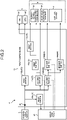
- FIG. 1 is a block diagram of the vehicle communication apparatus according to the embodiment
- FIG. 2 is a configuration diagram of a power source controller according to the embodiment
- FIG. 3 is a diagram illustrating the vehicle communication apparatus when an ACC is in an OFF state in a normal state
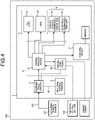
- FIG. 4 is a diagram illustrating the vehicle communication apparatus when the ACC is in an ON state in the normal state
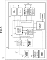
- FIG. 5 is a diagram illustrating the vehicle communication apparatus when power supply from an external power source cannot be received.
- a vehicle communication apparatus 1 in the present embodiment is mounted on a vehicle 100.
- the vehicle 100 is, for example, an automobile.
- the type of the vehicle 100 is not particularly limited and may be a passenger automobile, an omnibus such as a bus, or a cargo automobile such as a truck.
- the vehicle 100 may be a hybrid vehicle or a plug-in hybrid vehicle.
- the exemplified vehicle communication apparatus 1 is configured as an on-vehicle router.
- the vehicle communication apparatus 1 relays communication among a plurality of networks.
- the vehicle communication apparatus 1 may be a gateway.
- the vehicle communication apparatus 1 includes an internal power source 2, a changeover switch 3, a power source controller 4, an emergency communication unit 5, a second communication device 6, and a control device 7.
- the vehicle communication apparatus 1 is connected to an external power source 101.
- the external power source 101 is a power source arranged outside the vehicle communication apparatus 1.
- the external power source 101 is a chargeable and dischargeable secondary battery and is, for example, a lead battery or a lithium ion battery.
- the external power source 101 may be a power source for an auxiliary machine or may be a power source for a running motor of the vehicle 100.
- the external power source 101 is charged with electric power generated by an alternator of the vehicle 100 or electric power generated by regeneration.
- the external power source 101 may be capable of being charged with electric power supplied from the outside of the vehicle 100.
- the internal power source 2 is a backup power source arranged in the vehicle communication apparatus 1.
- the internal power source 2 is accommodated in, for example, a housing included in the vehicle communication apparatus 1.
- the internal power source 2 is a chargeable and dischargeable secondary battery and is, for example, a lead battery or a lithium ion battery.
- the changeover switch 3 is connected to the external power source 101 through a first power source line 102.
- the changeover switch 3 is connected to the internal power source 2 through a second power source line 20.
- the changeover switch 3 connects power source of either the external power source 101 or the internal power source 2 to a power source block 41.
- the changeover switch 3 may be capable of connecting the external power source 101 and the internal power source 2.
- the changeover switch 3 connects the external power source 101 to the power source block 41 when power supply from the external power source 101 can be received.
- the changeover switch 3 connects the internal power source 2 to the power source block 41 when power supply from the external power source 101 cannot be received.
- the changeover switch 3 is configured to be automatically switched in accordance with a voltage of the first power source line 102, for example. In this case, when the voltage of the first power source line 102 is higher than a predetermined threshold, the changeover switch 3 connects the external power source 101 to the power source block 41. On the other hand, when the voltage of the first power source line 102 is lowered to be equal to or lower than a predetermined lower limit value, the changeover switch 3 connects, to the power source block 41, the internal power source 2 instead of the external power source 101.
- the power source controller 4 includes the power source block 41 and a microcomputer 42.
- the power source block 41 includes a switch circuit configured to control power supply to each of loads of the vehicle communication apparatus 1.
- the power source block 41 includes an input portion 40, a plurality of first switches 43, and a plurality of second switches 44.
- the input portion 40 is connected to the changeover switch 3. That is to say, the input portion 40 is selectively connected to the external power source 101 or the internal power source 2.
- the first switches 43 and the second switches 44 are, for example, power source ICs.
- the first switches 43 are automatically switched into either of conduction states or cut-off states. That is to say, the first switches 43 are autonomously switched to be turned ON/OFF. The first switches 43 are brought into the conduction states when a voltage on the power source side is higher than the predetermined threshold. On the other hand, the first switches 43 are brought into the cut-off states when the voltage on the power source side is lower than the predetermined lower limit value.
- the first switches 43 may include protection circuits against overcurrent or the like.
- the second switches 44 are switched into either of conduction states or cut-off states in accordance with control signals.
- the second switches 44 are connected to the microcomputer 42 and are controlled by the control signals output from the microcomputer 42.
- the exemplified power source block 41 includes four switches 43a, 43b, 43c, and 43d as the first switches 43.
- the switch 43a is interposed between the input portion 40 and the microcomputer 42. Accordingly, the microcomputer 42 can receive power supply all the time from either of the external power source 101 or the internal power source 2.
- the switch 43b is interposed between the input portion 40 and the emergency communication unit 5. Accordingly, the emergency communication unit 5 can receive power supply all the time from either of the external power source 101 or the internal power source 2.
- the exemplified power source block 41 includes four switches 44a, 44b, 44c, and 44d as the second switches 44.
- the second communication device 6 and the control device 7 are connected to the input portion 40 through either of the switch 44a or 44b.
- the power source block 41 can therefore cut off the second communication device 6 and the control device 7 from the external power source 101 and the internal power source 2.
- the microcomputer 42 is a microcomputer including a control circuit.
- the microcomputer 42 is programmed to control the second switches 44.
- the microcomputer 42 has a function of CAN communication and makes communication with devices of the vehicle 100 via a controller area network (CAN).
- the microcomputer 42 is connected to the changeover switch 3 and monitors the changeover switch 3.
- the microcomputer 42 acquires a state of the changeover switch 3 based on output from the changeover switch 3, for example.
- the microcomputer 42 acquires, for example, an ignition signal (IG signal), an ACC signal, an airbag signal, and the like by the CAN communication.
- the airbag signal is a signal that is output when an airbag is deployed.
- the microcomputer 42 is connected to an external emergency call button 103. When the emergency call button 103 is pressed, the microcomputer 42 detects a press signal.
- the emergency communication unit 5 includes a first communication device 51 and a position calculation device 52.
- the first communication device 51 is a device to make an emergency call from the vehicle 100 to the outside of the vehicle in an emergency.
- the first communication device 51 is configured to make wireless communication and makes wireless communication with a wireless base station of a communication provider, for example.
- the first communication device 51 makes mobile communication of long term evolution (LTE)/4th generation (4G), for example.
- LTE long term evolution
- 4G fourthth generation
- the position calculation device 52 is a device to receive satellite radio waves and calculate a position of the vehicle 100.
- the radio waves that are received are, for example, transmitted from global positioning system (GPS) satellites.
- GPS global positioning system
- the first communication device 51 acquires positional information of the vehicle 100 from the position calculation device 52.
- the first communication device 51 may periodically transmit the acquired positional information to a cloud server or the like.
- the first communication device 51 is configured to make an emergency call.
- the emergency call is executed when a collision is detected in the vehicle 100 or by an operation of a passenger of the vehicle 100.
- the emergency call is executed by, for example, an instruction by the microcomputer 42.
- the microcomputer 42 detects a collision detection signal output from a sensor or an electronic control unit mounted on the vehicle 100, it instructs the first communication device 51 to execute the emergency call.
- the first communication device 51 connects to an emergency call center (call center) to enable conversations between the passenger and an operator.
- the first communication device 51 can transmit a present position of the vehicle 100 in the emergency call.
- the second communication device 6 includes an out-of-vehicle communication block 61 and an in-vehicle communication unit 62.
- the out-of-vehicle communication block 61 includes a wireless communication circuit for making communication with the outside of the vehicle for connected services.
- the out-of-vehicle communication block 61 is configured to be capable of making Wi-Fi communication, for example.
- the in-vehicle communication unit 62 has an interface such as Ethernet (registered trademark) for making communication with an engine control unit (ECU) mounted on the vehicle 100.
- the control device 7 includes a control circuit configured to collectively control the vehicle communication apparatus 1.
- the control device 7 is, for example, a system-on-a-chip (SoC).
- SoC system-on-a-chip
- the control device 7 controls, for example, wireless communication by the out-of-vehicle communication block 61 and communication by the in-vehicle communication unit 62.
- the control device 7 may be configured to execute a function of monitoring the internal power source 2 and charging control on the internal power source 2.
- the microcomputer 42 may execute monitoring and charging control on the internal power source 2.
- FIG. 3 illustrates the vehicle communication apparatus 1 when the ACC is in the OFF state in the normal state.
- the normal state indicates that power supply from the external power source 101 can be regularly received, for example.
- the changeover switch 3 connects the external power source 101 to the power source block 41 in the normal state.
- the power source block 41 connects the microcomputer 42 and the emergency communication unit 5 to the power source.
- the first switches 43 of the power source block 41 automatically connect the microcomputer 42 and the emergency communication unit 5 to the external power source 101.
- the microcomputer 42 cuts off the second communication device 6 and the control device 7 from the power source when the ACC is in the OFF state.
- the microcomputer 42 outputs signals for bringing the switches 44a and 44b into the cut-off states, for example.
- FIG. 4 illustrates the vehicle communication apparatus 1 when the ACC is in the ON state in the normal state.
- the microcomputer 42 connects the second communication device 6 and the control device 7 to the power source when the ACC of the vehicle 100 is turned into the ON state.
- the microcomputer 42 outputs signals for bringing all the second switches 44 into the connected states, for example. That is to say, the power source controller 4 supplies electric power supplied from the external power source 101 to the microcomputer 42, the emergency communication unit 5, the second communication device 6, and the control device 7.
- FIG. 5 illustrates the vehicle communication apparatus 1 when power supply from the external power source 101 cannot be received.
- the changeover switch 3 connects the internal power source 2 to the power source block 41.
- the first switches 43 of the power source block 41 automatically connect the internal power source 2 to the microcomputer 42 and the emergency communication unit 5. That is to say, the microcomputer 42 and the emergency communication unit 5 operate with electric power of the internal power source 2.
- the microcomputer 42 When the microcomputer 42 detects that the internal power source 2 is connected to the power source block 41 by the changeover switch 3, it prohibits power supply to the second communication device 6 and the control device 7. In this case, the microcomputer 42 outputs the signals for bringing the switches 44a and 44b into the cut-off states, for example. As illustrated in FIG. 5 , the second communication device 6 and the control device 7 are thereby cut off from the internal power source 2. That is to say, in the vehicle communication apparatus 1, functions other than functions necessary for the emergency call are turned OFF and priority is given to ensuring of electric power for the emergency call.
- the microcomputer 42 When the microcomputer 42 detects a predetermined signal, it causes the first communication device 51 to execute the emergency call.
- the predetermined signal is the collision detection signal, the airbag signal, the press signal of the emergency call button 103, and the like.
- the first communication device 51 executes the emergency call with electric power from the internal power source 2. In this case, since no power is supplied to the second communication device 6 and the control device 7, power consumption in the vehicle communication apparatus 1 is reduced. In other words, electric power is preferentially supplied to the emergency communication unit 5 at the time of the emergency call. Accordingly, sufficient electric power can be supplied to the emergency communication unit 5 even with the internal power source 2 having a small capacity.
- the internal power source 2 having the small capacity enables a long emergency conversation and emergency communication time. That is to say, both of ensuring of electric power for the emergency call and reduction in the capacity of the internal power source 2 can be achieved.
- the reduction in the capacity of the internal power source 2 enables cost reduction and miniaturization and weight reduction of the vehicle communication apparatus 1.
- the vehicle communication apparatus 1 includes the first communication device 51, the second communication device 6, the internal power source 2, and the power source controller 4.
- the first communication device 51 makes the emergency call from the vehicle 100 to the outside of the vehicle at the time of the emergency.
- the second communication device 6 makes communication differing from the emergency call.
- the power source controller 4 can be connected to the internal power source 2 and the external power source 101, and controls power supply to the first communication device 51 and the second communication device 6.
- the power source controller 4 supplies electric power of the internal power source 2 to the first communication device 51 and prohibits power supply to the second communication device 6 from the internal power source 2 when power supply from the external power source 101 cannot be received.
- the vehicle communication apparatus 1 according to the present embodiment can achieve both of miniaturization of the integrated communication apparatus including the device for the emergency call and ensuring of electric power that is supplied to the first communication device 51 configured to make the emergency call.
- the vehicle communication apparatus 1 includes the position calculation device 52.
- the position calculation device 52 receives the satellite radio waves and calculates the position of the vehicle 100.
- the power source controller 4 supplies electric power of the internal power source 2 to the position calculation device 52 when power supply from the external power source 101 cannot be received.
- the positional information of the vehicle 100 can therefore be utilized when the emergency call is executed.
- the power source controller 4 of the present embodiment includes the power source block 41 and the microcomputer 42.
- the power source block 41 includes the controllable second switches 44.
- the microcomputer 42 controls the second switches 44.
- the power source block 41 supplies electric power of the internal power source 2 to the microcomputer 42 and the microcomputer 42 brings the second switches 44 between the internal power source 2 and the second communication device 6 into the cut-off states. Therefore, the power consumption of the vehicle communication apparatus 1 can be appropriately reduced by the microcomputer 42 and the second switches 44.
- the first communication device 51 may execute emergency data communication instead of the conversations or in addition to the conversations at the time of the emergency call. For example, the first communication device 51 may transmit, to the emergency call center, data indicating the present position of the vehicle 100 and detection of the collision detection signal at the time of the emergency call.
- the configuration of the vehicle communication apparatus 1 is not limited to the configuration exemplified in the above-mentioned embodiment.
- the vehicle communication apparatus 1 may include a communication device for wireless communication in the vehicle.
- the second switches 44 may be arranged between the power source and the emergency communication unit 5.
- the second switches 44 arranged between the power source and the emergency communication unit 5 are controlled by the microcomputer 42.
- the vehicle communication apparatus supplies electric power of the internal power source to the first communication device and prohibits power supply to the second communication device from the internal power source when power supply from the external power source cannot be received.
- the vehicle communication apparatus provides an effect of achieving both of miniaturization of the apparatus and ensuring of electric power that is supplied to the communication device configured to make the emergency call.
Landscapes
- Engineering & Computer Science (AREA)
- Physics & Mathematics (AREA)
- General Physics & Mathematics (AREA)
- Mechanical Engineering (AREA)
- Transportation (AREA)
- Automation & Control Theory (AREA)
- Business, Economics & Management (AREA)
- Computer Security & Cryptography (AREA)
- Emergency Management (AREA)
- Power Engineering (AREA)
- Signal Processing (AREA)
- Computer Networks & Wireless Communication (AREA)
- Alarm Systems (AREA)
- Telephone Function (AREA)
Abstract
A vehicle communication apparatus (1) includes a first communication device (51) that makes an emergency call from a vehicle (100) to the outside of the vehicle at the time of an emergency, a second communication device (6) that makes communication differing from the emergency call, an internal power source (2), and a power source controller (4) that can be connected to the internal power source and an external power source (101) mounted on the vehicle and controls power supply to the first communication device and the second communication device. The power source controller (4) supplies electric power of the internal power source (2) to the first communication device (51) and prohibits power supply to the second communication device (6) from the internal power source (2) when power supply from the external power source (101) cannot be received.
Description
- The present invention relates to a vehicle communication apparatus.
- Conventionally, there is a technique of making an emergency call.
Japanese Patent Application Laid-open No. 2015-159370 - Here, it is preferable that a communication device configured to make an emergency call and a communication device configured to make communication differing from the emergency call can be integrated to achieve miniaturization of an apparatus. On the other hand, a power source for the emergency call can be desirably ensured in the integrated apparatus. For example, priority can be desirably given to power supply to the communication device configured to make the emergency call.
- An object of the present invention is to provide a vehicle communication apparatus capable of achieving both of miniaturization of the apparatus and ensuring of electric power that is supplied to a communication device configured to make an emergency call.
- In order to achieve the above mentioned object, a vehicle communication apparatus according to one aspect of the present invention includes a first communication device that makes an emergency call from a vehicle to outside of the vehicle at the time of an emergency; a second communication device that makes communication differing from the emergency call; an internal power source; and a power source controller that is connectable to the internal power source and an external power source mounted on the vehicle and configured to control power supply to the first communication device and the second communication device, wherein the power source controller supplies electric power of the internal power source to the first communication device and prohibits power supply to the second communication device from the internal power source when power supply from the external power source is not receivable.
- According to another aspect of the present invention, in the vehicle communication apparatus, it is preferable to further include a position calculation device that receives satellite radio waves and calculates a position of the vehicle, wherein the power source controller supplies electric power of the internal power source to the position calculation device when power supply from the external power source is not receivable.
- According to still another aspect of the present invention, in the vehicle communication apparatus, it is preferable that the power source controller includes a power source block having a controllable switch and a microcomputer controlling the switch, and when power supply from the external power source is not receivable, the power source block supplies electric power of the internal power source to the microcomputer, and the microcomputer brings the switch between the internal power source and the second communication device into a cut-off state.
- The above and other objects, features, advantages and technical and industrial significance of this invention will be better understood by reading the following detailed description of presently preferred embodiments of the invention, when considered in connection with the accompanying drawings.
-
-
FIG. 1 is a block diagram of a vehicle communication apparatus according to an embodiment; -
FIG. 2 is a configuration diagram of a power source controller according to the embodiment; -
FIG. 3 is a diagram illustrating the vehicle communication apparatus when an ACC is in an OFF state in a normal state; -
FIG. 4 is a diagram illustrating the vehicle communication apparatus when the ACC is in an ON state in the normal state; and -
FIG. 5 is a diagram illustrating the vehicle communication apparatus when power supply from an external power source cannot be received. - Hereinafter, a vehicle communication apparatus according to an embodiment of the present invention will be described in detail with reference to the drawings. The embodiment does not limit the present invention. Components in the following embodiment include those that can be easily assumed by those skilled in the art and substantially the same components.
- An embodiment will be described with reference to
FIG. 1 to FIG. 5 . The present embodiment relates to a vehicle communication apparatus.FIG. 1 is a block diagram of the vehicle communication apparatus according to the embodiment,FIG. 2 is a configuration diagram of a power source controller according to the embodiment,FIG. 3 is a diagram illustrating the vehicle communication apparatus when an ACC is in an OFF state in a normal state,FIG. 4 is a diagram illustrating the vehicle communication apparatus when the ACC is in an ON state in the normal state, andFIG. 5 is a diagram illustrating the vehicle communication apparatus when power supply from an external power source cannot be received. - As illustrated in
FIG. 1 , a vehicle communication apparatus 1 in the present embodiment is mounted on avehicle 100. Thevehicle 100 is, for example, an automobile. The type of thevehicle 100 is not particularly limited and may be a passenger automobile, an omnibus such as a bus, or a cargo automobile such as a truck. Thevehicle 100 may be a hybrid vehicle or a plug-in hybrid vehicle. - The exemplified vehicle communication apparatus 1 is configured as an on-vehicle router. The vehicle communication apparatus 1 relays communication among a plurality of networks. The vehicle communication apparatus 1 may be a gateway. The vehicle communication apparatus 1 includes an
internal power source 2, achangeover switch 3, apower source controller 4, anemergency communication unit 5, asecond communication device 6, and acontrol device 7. - The vehicle communication apparatus 1 is connected to an
external power source 101. Theexternal power source 101 is a power source arranged outside the vehicle communication apparatus 1. Theexternal power source 101 is a chargeable and dischargeable secondary battery and is, for example, a lead battery or a lithium ion battery. Theexternal power source 101 may be a power source for an auxiliary machine or may be a power source for a running motor of thevehicle 100. Theexternal power source 101 is charged with electric power generated by an alternator of thevehicle 100 or electric power generated by regeneration. Theexternal power source 101 may be capable of being charged with electric power supplied from the outside of thevehicle 100. - The
internal power source 2 is a backup power source arranged in the vehicle communication apparatus 1. Theinternal power source 2 is accommodated in, for example, a housing included in the vehicle communication apparatus 1. Theinternal power source 2 is a chargeable and dischargeable secondary battery and is, for example, a lead battery or a lithium ion battery. - The
changeover switch 3 is connected to theexternal power source 101 through a firstpower source line 102. Thechangeover switch 3 is connected to theinternal power source 2 through a secondpower source line 20. Thechangeover switch 3 connects power source of either theexternal power source 101 or theinternal power source 2 to apower source block 41. Thechangeover switch 3 may be capable of connecting theexternal power source 101 and theinternal power source 2. Thechangeover switch 3 connects theexternal power source 101 to thepower source block 41 when power supply from theexternal power source 101 can be received. On the other hand, thechangeover switch 3 connects theinternal power source 2 to thepower source block 41 when power supply from theexternal power source 101 cannot be received. - The
changeover switch 3 is configured to be automatically switched in accordance with a voltage of the firstpower source line 102, for example. In this case, when the voltage of the firstpower source line 102 is higher than a predetermined threshold, thechangeover switch 3 connects theexternal power source 101 to thepower source block 41. On the other hand, when the voltage of the firstpower source line 102 is lowered to be equal to or lower than a predetermined lower limit value, thechangeover switch 3 connects, to thepower source block 41, theinternal power source 2 instead of theexternal power source 101. - The
power source controller 4 includes thepower source block 41 and amicrocomputer 42. Thepower source block 41 includes a switch circuit configured to control power supply to each of loads of the vehicle communication apparatus 1. As illustrated inFIG. 2 , thepower source block 41 includes aninput portion 40, a plurality offirst switches 43, and a plurality ofsecond switches 44. Theinput portion 40 is connected to thechangeover switch 3. That is to say, theinput portion 40 is selectively connected to theexternal power source 101 or theinternal power source 2. Thefirst switches 43 and thesecond switches 44 are, for example, power source ICs. - The
first switches 43 are automatically switched into either of conduction states or cut-off states. That is to say, thefirst switches 43 are autonomously switched to be turned ON/OFF. Thefirst switches 43 are brought into the conduction states when a voltage on the power source side is higher than the predetermined threshold. On the other hand, thefirst switches 43 are brought into the cut-off states when the voltage on the power source side is lower than the predetermined lower limit value. The first switches 43 may include protection circuits against overcurrent or the like. - The second switches 44 are switched into either of conduction states or cut-off states in accordance with control signals. The second switches 44 are connected to the
microcomputer 42 and are controlled by the control signals output from themicrocomputer 42. - The exemplified
power source block 41 includes fourswitches switch 43a is interposed between theinput portion 40 and themicrocomputer 42. Accordingly, themicrocomputer 42 can receive power supply all the time from either of theexternal power source 101 or theinternal power source 2. Theswitch 43b is interposed between theinput portion 40 and theemergency communication unit 5. Accordingly, theemergency communication unit 5 can receive power supply all the time from either of theexternal power source 101 or theinternal power source 2. - The exemplified
power source block 41 includes fourswitches second communication device 6 and thecontrol device 7 are connected to theinput portion 40 through either of theswitch power source block 41 can therefore cut off thesecond communication device 6 and thecontrol device 7 from theexternal power source 101 and theinternal power source 2. - The
microcomputer 42 is a microcomputer including a control circuit. Themicrocomputer 42 is programmed to control the second switches 44. Themicrocomputer 42 has a function of CAN communication and makes communication with devices of thevehicle 100 via a controller area network (CAN). Themicrocomputer 42 is connected to thechangeover switch 3 and monitors thechangeover switch 3. Themicrocomputer 42 acquires a state of thechangeover switch 3 based on output from thechangeover switch 3, for example. Themicrocomputer 42 acquires, for example, an ignition signal (IG signal), an ACC signal, an airbag signal, and the like by the CAN communication. The airbag signal is a signal that is output when an airbag is deployed. Themicrocomputer 42 is connected to an externalemergency call button 103. When theemergency call button 103 is pressed, themicrocomputer 42 detects a press signal. - The
emergency communication unit 5 includes afirst communication device 51 and aposition calculation device 52. Thefirst communication device 51 is a device to make an emergency call from thevehicle 100 to the outside of the vehicle in an emergency. Thefirst communication device 51 is configured to make wireless communication and makes wireless communication with a wireless base station of a communication provider, for example. Thefirst communication device 51 makes mobile communication of long term evolution (LTE)/4th generation (4G), for example. - The
position calculation device 52 is a device to receive satellite radio waves and calculate a position of thevehicle 100. The radio waves that are received are, for example, transmitted from global positioning system (GPS) satellites. Thefirst communication device 51 acquires positional information of thevehicle 100 from theposition calculation device 52. Thefirst communication device 51 may periodically transmit the acquired positional information to a cloud server or the like. - The
first communication device 51 is configured to make an emergency call. The emergency call is executed when a collision is detected in thevehicle 100 or by an operation of a passenger of thevehicle 100. The emergency call is executed by, for example, an instruction by themicrocomputer 42. When themicrocomputer 42 detects a collision detection signal output from a sensor or an electronic control unit mounted on thevehicle 100, it instructs thefirst communication device 51 to execute the emergency call. Thefirst communication device 51 connects to an emergency call center (call center) to enable conversations between the passenger and an operator. Thefirst communication device 51 can transmit a present position of thevehicle 100 in the emergency call. - The
second communication device 6 includes an out-of-vehicle communication block 61 and an in-vehicle communication unit 62. The out-of-vehicle communication block 61 includes a wireless communication circuit for making communication with the outside of the vehicle for connected services. The out-of-vehicle communication block 61 is configured to be capable of making Wi-Fi communication, for example. The in-vehicle communication unit 62 has an interface such as Ethernet (registered trademark) for making communication with an engine control unit (ECU) mounted on thevehicle 100. - The
control device 7 includes a control circuit configured to collectively control the vehicle communication apparatus 1. Thecontrol device 7 is, for example, a system-on-a-chip (SoC). Thecontrol device 7 controls, for example, wireless communication by the out-of-vehicle communication block 61 and communication by the in-vehicle communication unit 62. Thecontrol device 7 may be configured to execute a function of monitoring theinternal power source 2 and charging control on theinternal power source 2. Themicrocomputer 42 may execute monitoring and charging control on theinternal power source 2. -
FIG. 3 illustrates the vehicle communication apparatus 1 when the ACC is in the OFF state in the normal state. The normal state indicates that power supply from theexternal power source 101 can be regularly received, for example. Thechangeover switch 3 connects theexternal power source 101 to thepower source block 41 in the normal state. When the ACC of thevehicle 100 is in the OFF state, thepower source block 41 connects themicrocomputer 42 and theemergency communication unit 5 to the power source. The first switches 43 of thepower source block 41 automatically connect themicrocomputer 42 and theemergency communication unit 5 to theexternal power source 101. Themicrocomputer 42 cuts off thesecond communication device 6 and thecontrol device 7 from the power source when the ACC is in the OFF state. Themicrocomputer 42 outputs signals for bringing theswitches -
FIG. 4 illustrates the vehicle communication apparatus 1 when the ACC is in the ON state in the normal state. Themicrocomputer 42 connects thesecond communication device 6 and thecontrol device 7 to the power source when the ACC of thevehicle 100 is turned into the ON state. Themicrocomputer 42 outputs signals for bringing all thesecond switches 44 into the connected states, for example. That is to say, thepower source controller 4 supplies electric power supplied from theexternal power source 101 to themicrocomputer 42, theemergency communication unit 5, thesecond communication device 6, and thecontrol device 7. -
FIG. 5 illustrates the vehicle communication apparatus 1 when power supply from theexternal power source 101 cannot be received. When abnormality such as a defect is generated in theexternal power source 101 or the firstpower source line 102 is disconnected, thechangeover switch 3 connects theinternal power source 2 to thepower source block 41. The first switches 43 of thepower source block 41 automatically connect theinternal power source 2 to themicrocomputer 42 and theemergency communication unit 5. That is to say, themicrocomputer 42 and theemergency communication unit 5 operate with electric power of theinternal power source 2. - When the
microcomputer 42 detects that theinternal power source 2 is connected to thepower source block 41 by thechangeover switch 3, it prohibits power supply to thesecond communication device 6 and thecontrol device 7. In this case, themicrocomputer 42 outputs the signals for bringing theswitches FIG. 5 , thesecond communication device 6 and thecontrol device 7 are thereby cut off from theinternal power source 2. That is to say, in the vehicle communication apparatus 1, functions other than functions necessary for the emergency call are turned OFF and priority is given to ensuring of electric power for the emergency call. - When the
microcomputer 42 detects a predetermined signal, it causes thefirst communication device 51 to execute the emergency call. The predetermined signal is the collision detection signal, the airbag signal, the press signal of theemergency call button 103, and the like. Thefirst communication device 51 executes the emergency call with electric power from theinternal power source 2. In this case, since no power is supplied to thesecond communication device 6 and thecontrol device 7, power consumption in the vehicle communication apparatus 1 is reduced. In other words, electric power is preferentially supplied to theemergency communication unit 5 at the time of the emergency call. Accordingly, sufficient electric power can be supplied to theemergency communication unit 5 even with theinternal power source 2 having a small capacity. Theinternal power source 2 having the small capacity enables a long emergency conversation and emergency communication time. That is to say, both of ensuring of electric power for the emergency call and reduction in the capacity of theinternal power source 2 can be achieved. The reduction in the capacity of theinternal power source 2 enables cost reduction and miniaturization and weight reduction of the vehicle communication apparatus 1. - As described above, the vehicle communication apparatus 1 according to the present embodiment includes the
first communication device 51, thesecond communication device 6, theinternal power source 2, and thepower source controller 4. Thefirst communication device 51 makes the emergency call from thevehicle 100 to the outside of the vehicle at the time of the emergency. Thesecond communication device 6 makes communication differing from the emergency call. Thepower source controller 4 can be connected to theinternal power source 2 and theexternal power source 101, and controls power supply to thefirst communication device 51 and thesecond communication device 6. - The
power source controller 4 supplies electric power of theinternal power source 2 to thefirst communication device 51 and prohibits power supply to thesecond communication device 6 from theinternal power source 2 when power supply from theexternal power source 101 cannot be received. The vehicle communication apparatus 1 according to the present embodiment can achieve both of miniaturization of the integrated communication apparatus including the device for the emergency call and ensuring of electric power that is supplied to thefirst communication device 51 configured to make the emergency call. - The vehicle communication apparatus 1 according to the present embodiment includes the
position calculation device 52. Theposition calculation device 52 receives the satellite radio waves and calculates the position of thevehicle 100. Thepower source controller 4 supplies electric power of theinternal power source 2 to theposition calculation device 52 when power supply from theexternal power source 101 cannot be received. The positional information of thevehicle 100 can therefore be utilized when the emergency call is executed. - The
power source controller 4 of the present embodiment includes thepower source block 41 and themicrocomputer 42. Thepower source block 41 includes the controllable second switches 44. Themicrocomputer 42 controls the second switches 44. When power supply from theexternal power source 101 cannot be received, thepower source block 41 supplies electric power of theinternal power source 2 to themicrocomputer 42 and themicrocomputer 42 brings thesecond switches 44 between theinternal power source 2 and thesecond communication device 6 into the cut-off states. Therefore, the power consumption of the vehicle communication apparatus 1 can be appropriately reduced by themicrocomputer 42 and the second switches 44. - The
first communication device 51 may execute emergency data communication instead of the conversations or in addition to the conversations at the time of the emergency call. For example, thefirst communication device 51 may transmit, to the emergency call center, data indicating the present position of thevehicle 100 and detection of the collision detection signal at the time of the emergency call. - The configuration of the vehicle communication apparatus 1 is not limited to the configuration exemplified in the above-mentioned embodiment. For example, the vehicle communication apparatus 1 may include a communication device for wireless communication in the vehicle. The second switches 44 may be arranged between the power source and the
emergency communication unit 5. In this case, thesecond switches 44 arranged between the power source and theemergency communication unit 5 are controlled by themicrocomputer 42. - Contents disclosed in the above-mentioned embodiment and modification can be appropriately combined for execution.
- The vehicle communication apparatus according to the present embodiment supplies electric power of the internal power source to the first communication device and prohibits power supply to the second communication device from the internal power source when power supply from the external power source cannot be received. The vehicle communication apparatus according to the present embodiment provides an effect of achieving both of miniaturization of the apparatus and ensuring of electric power that is supplied to the communication device configured to make the emergency call.
- Although the invention has been described with respect to specific embodiments for a complete and clear disclosure, the appended claims are not to be thus limited but are to be construed as embodying all modifications and alternative constructions that may occur to one skilled in the art that fairly fall within the basic teaching herein set forth.
Claims (3)
- A vehicle communication apparatus (1) comprising:a first communication device (51) that makes an emergency call from a vehicle (100) to outside of the vehicle (100) at the time of an emergency;a second communication device (6) that makes communication differing from the emergency call;an internal power source (2); anda power source controller (4) that is connectable to the internal power source (2) and an external power source (101) mounted on the vehicle (100) and configured to control power supply to the first communication device (51) and the second communication device (6), whereinthe power source controller (4) supplies electric power of the internal power source (2) to the first communication device (51) and prohibits power supply to the second communication device (6) from the internal power source (2) when power supply from the external power source (101) is not receivable.
- The vehicle communication apparatus (1) according to claim 1, further comprising:a position calculation device (52) that receives satellite radio waves and calculates a position of the vehicle (100), whereinthe power source controller (4) supplies electric power of the internal power source (2) to the position calculation device (52) when power supply from the external power source (101) is not receivable.
- The vehicle communication apparatus (1) according to claim 1 or 2, whereinthe power source controller (4) includes a power source block (41) having a controllable switch (44) and a microcomputer (42) controlling the switch (44), andwhen power supply from the external power source (101) is not receivable, the power source block (41) supplies electric power of the internal power source (2) to the microcomputer (42), and the microcomputer (42) brings the switch (44) between the internal power source (2) and the second communication device (6) into a cut-off state.
Applications Claiming Priority (1)
| Application Number | Priority Date | Filing Date | Title |
|---|---|---|---|
| JP2021040896A JP2022140868A (en) | 2021-03-15 | 2021-03-15 | Vehicular communication device |
Publications (1)
| Publication Number | Publication Date |
|---|---|
| EP4060637A1 true EP4060637A1 (en) | 2022-09-21 |
Family
ID=80999734
Family Applications (1)
| Application Number | Title | Priority Date | Filing Date |
|---|---|---|---|
| EP22161088.4A Withdrawn EP4060637A1 (en) | 2021-03-15 | 2022-03-09 | Vehicle communication apparatus |
Country Status (4)
| Country | Link |
|---|---|
| US (1) | US20220289167A1 (en) |
| EP (1) | EP4060637A1 (en) |
| JP (1) | JP2022140868A (en) |
| CN (1) | CN115085353A (en) |
Citations (3)
| Publication number | Priority date | Publication date | Assignee | Title |
|---|---|---|---|---|
| JP2015159370A (en) | 2014-02-21 | 2015-09-03 | 本田技研工業株式会社 | Emergency call system |
| US20170099594A1 (en) * | 2015-10-06 | 2017-04-06 | Hyundai Motor Company | Method for operating audio, video, and navigation (avn) system, avn system, and vehicle including the same |
| JP2021009512A (en) * | 2019-06-28 | 2021-01-28 | ダイハツ工業株式会社 | Accident reporting device |
Family Cites Families (1)
| Publication number | Priority date | Publication date | Assignee | Title |
|---|---|---|---|---|
| JP2015020619A (en) * | 2013-07-19 | 2015-02-02 | 株式会社オートネットワーク技術研究所 | Vehicle power feed device |
-
2021
- 2021-03-15 JP JP2021040896A patent/JP2022140868A/en active Pending
-
2022
- 2022-03-07 CN CN202210216761.5A patent/CN115085353A/en not_active Withdrawn
- 2022-03-08 US US17/689,939 patent/US20220289167A1/en not_active Abandoned
- 2022-03-09 EP EP22161088.4A patent/EP4060637A1/en not_active Withdrawn
Patent Citations (3)
| Publication number | Priority date | Publication date | Assignee | Title |
|---|---|---|---|---|
| JP2015159370A (en) | 2014-02-21 | 2015-09-03 | 本田技研工業株式会社 | Emergency call system |
| US20170099594A1 (en) * | 2015-10-06 | 2017-04-06 | Hyundai Motor Company | Method for operating audio, video, and navigation (avn) system, avn system, and vehicle including the same |
| JP2021009512A (en) * | 2019-06-28 | 2021-01-28 | ダイハツ工業株式会社 | Accident reporting device |
Also Published As
| Publication number | Publication date |
|---|---|
| JP2022140868A (en) | 2022-09-29 |
| CN115085353A (en) | 2022-09-20 |
| US20220289167A1 (en) | 2022-09-15 |
Similar Documents
| Publication | Publication Date | Title |
|---|---|---|
| EP3107181B1 (en) | Monitoring device for secondary battery, battery pack, and protection system for secondary battery | |
| US20250091536A1 (en) | Vehicle electrical system and method for the operation thereof | |
| US12012057B2 (en) | Power network for a motor vehicle and method for operating a power network for a motor vehicle | |
| EP3993221B1 (en) | Power supply control system | |
| JP2018103972A (en) | On-vehicle control device | |
| US11114877B2 (en) | Battery device and vehicle | |
| US10623239B1 (en) | Multiple antenna telematics controller radio recovery | |
| US20220321684A1 (en) | Wireless communication apparatus and vehicle | |
| CN111918787B (en) | Systems and methods for controlling relays using triggers | |
| EP4060637A1 (en) | Vehicle communication apparatus | |
| US12356305B2 (en) | Reliable and automatic on-board unit for vehicles in distress, movable device, and method of controlling same | |
| EP4068547B1 (en) | Vehicle-mounted battery system | |
| CN115848151B (en) | Relay control circuit system and control method thereof | |
| JP2021009512A (en) | Accident reporting device | |
| KR20250067215A (en) | Apparatus and method for protecting battery pack of vehicle | |
| JP3700417B2 (en) | Automatic emergency call device | |
| KR102043989B1 (en) | Apparatus and method for controlling power of a vehicle | |
| US12503009B2 (en) | Vehicle | |
| JP2022115152A (en) | On-vehicle emergency power supply and vehicle mounted with on-vehicle emergency power supply | |
| JP2001088631A (en) | In-vehicle communication terminal device | |
| US20250368089A1 (en) | Replacement system for power storage device | |
| US11876300B2 (en) | Antenna system for a vehicle | |
| CN114285499B (en) | Detection system and detection method of vehicle-mounted TBOX external antenna | |
| JP7636237B2 (en) | Power Equipment | |
| WO2024134261A1 (en) | Modular battery of an electric vehicle |
Legal Events
| Date | Code | Title | Description |
|---|---|---|---|
| PUAI | Public reference made under article 153(3) epc to a published international application that has entered the european phase |
Free format text: ORIGINAL CODE: 0009012 |
|
| STAA | Information on the status of an ep patent application or granted ep patent |
Free format text: STATUS: REQUEST FOR EXAMINATION WAS MADE |
|
| 17P | Request for examination filed |
Effective date: 20220309 |
|
| AK | Designated contracting states |
Kind code of ref document: A1 Designated state(s): AL AT BE BG CH CY CZ DE DK EE ES FI FR GB GR HR HU IE IS IT LI LT LU LV MC MK MT NL NO PL PT RO RS SE SI SK SM TR |
|
| RAP3 | Party data changed (applicant data changed or rights of an application transferred) |
Owner name: YAZAKI CORPORATION |
|
| STAA | Information on the status of an ep patent application or granted ep patent |
Free format text: STATUS: THE APPLICATION HAS BEEN WITHDRAWN |
|
| 18W | Application withdrawn |
Effective date: 20240220 |