EP4060421A1 - Particulate capturing device and image forming device - Google Patents
Particulate capturing device and image forming device Download PDFInfo
- Publication number
- EP4060421A1 EP4060421A1 EP20888174.8A EP20888174A EP4060421A1 EP 4060421 A1 EP4060421 A1 EP 4060421A1 EP 20888174 A EP20888174 A EP 20888174A EP 4060421 A1 EP4060421 A1 EP 4060421A1
- Authority
- EP
- European Patent Office
- Prior art keywords
- air
- plate
- vent
- capturing device
- image forming
- Prior art date
- Legal status (The legal status is an assumption and is not a legal conclusion. Google has not performed a legal analysis and makes no representation as to the accuracy of the status listed.)
- Pending
Links
- 239000010419 fine particle Substances 0.000 claims description 19
- 238000011144 upstream manufacturing Methods 0.000 claims description 7
- 239000011882 ultra-fine particle Substances 0.000 abstract description 54
- 238000009423 ventilation Methods 0.000 abstract description 2
- 238000012360 testing method Methods 0.000 description 39
- 229910052751 metal Inorganic materials 0.000 description 25
- 239000002184 metal Substances 0.000 description 25
- 230000009467 reduction Effects 0.000 description 20
- 229920000139 polyethylene terephthalate Polymers 0.000 description 18
- 239000005020 polyethylene terephthalate Substances 0.000 description 18
- 230000000694 effects Effects 0.000 description 16
- 238000012546 transfer Methods 0.000 description 16
- 239000007789 gas Substances 0.000 description 11
- 238000000034 method Methods 0.000 description 11
- 238000010586 diagram Methods 0.000 description 10
- 239000002245 particle Substances 0.000 description 10
- 238000010438 heat treatment Methods 0.000 description 9
- 239000000463 material Substances 0.000 description 8
- 230000002093 peripheral effect Effects 0.000 description 8
- 238000003825 pressing Methods 0.000 description 5
- 238000009941 weaving Methods 0.000 description 5
- 230000007423 decrease Effects 0.000 description 4
- 239000000428 dust Substances 0.000 description 4
- 239000000835 fiber Substances 0.000 description 4
- 238000012545 processing Methods 0.000 description 4
- 238000004080 punching Methods 0.000 description 4
- 238000012935 Averaging Methods 0.000 description 3
- 239000004745 nonwoven fabric Substances 0.000 description 3
- 229920000122 acrylonitrile butadiene styrene Polymers 0.000 description 2
- 230000008901 benefit Effects 0.000 description 2
- 230000008859 change Effects 0.000 description 2
- 238000004140 cleaning Methods 0.000 description 2
- 229910052878 cordierite Inorganic materials 0.000 description 2
- JSKIRARMQDRGJZ-UHFFFAOYSA-N dimagnesium dioxido-bis[(1-oxido-3-oxo-2,4,6,8,9-pentaoxa-1,3-disila-5,7-dialuminabicyclo[3.3.1]nonan-7-yl)oxy]silane Chemical compound [Mg++].[Mg++].[O-][Si]([O-])(O[Al]1O[Al]2O[Si](=O)O[Si]([O-])(O1)O2)O[Al]1O[Al]2O[Si](=O)O[Si]([O-])(O1)O2 JSKIRARMQDRGJZ-UHFFFAOYSA-N 0.000 description 2
- 238000004519 manufacturing process Methods 0.000 description 2
- 238000012986 modification Methods 0.000 description 2
- 230000004048 modification Effects 0.000 description 2
- 229910001220 stainless steel Inorganic materials 0.000 description 2
- 239000010935 stainless steel Substances 0.000 description 2
- 229920003002 synthetic resin Polymers 0.000 description 2
- 239000000057 synthetic resin Substances 0.000 description 2
- 230000007704 transition Effects 0.000 description 2
- XECAHXYUAAWDEL-UHFFFAOYSA-N acrylonitrile butadiene styrene Chemical compound C=CC=C.C=CC#N.C=CC1=CC=CC=C1 XECAHXYUAAWDEL-UHFFFAOYSA-N 0.000 description 1
- 239000004676 acrylonitrile butadiene styrene Substances 0.000 description 1
- 230000003213 activating effect Effects 0.000 description 1
- 229910052782 aluminium Inorganic materials 0.000 description 1
- XAGFODPZIPBFFR-UHFFFAOYSA-N aluminium Chemical compound [Al] XAGFODPZIPBFFR-UHFFFAOYSA-N 0.000 description 1
- 239000000919 ceramic Substances 0.000 description 1
- 229920006026 co-polymeric resin Polymers 0.000 description 1
- 238000009833 condensation Methods 0.000 description 1
- 230000005494 condensation Effects 0.000 description 1
- 239000000470 constituent Substances 0.000 description 1
- 238000001816 cooling Methods 0.000 description 1
- 239000013078 crystal Substances 0.000 description 1
- 230000006866 deterioration Effects 0.000 description 1
- 238000007599 discharging Methods 0.000 description 1
- 238000005553 drilling Methods 0.000 description 1
- 238000012840 feeding operation Methods 0.000 description 1
- 239000007788 liquid Substances 0.000 description 1
- 238000012423 maintenance Methods 0.000 description 1
- 239000012621 metal-organic framework Substances 0.000 description 1
- 230000001151 other effect Effects 0.000 description 1
- 239000011236 particulate material Substances 0.000 description 1
- 230000000149 penetrating effect Effects 0.000 description 1
- -1 polyethylene terephthalate Polymers 0.000 description 1
- 239000004800 polyvinyl chloride Substances 0.000 description 1
- 229920000915 polyvinyl chloride Polymers 0.000 description 1
- 239000013259 porous coordination polymer Substances 0.000 description 1
- 239000011148 porous material Substances 0.000 description 1
- 239000000843 powder Substances 0.000 description 1
- 230000008569 process Effects 0.000 description 1
- 230000004044 response Effects 0.000 description 1
- 238000007790 scraping Methods 0.000 description 1
- HBMJWWWQQXIZIP-UHFFFAOYSA-N silicon carbide Chemical group [Si+]#[C-] HBMJWWWQQXIZIP-UHFFFAOYSA-N 0.000 description 1
- 229910010271 silicon carbide Inorganic materials 0.000 description 1
- 238000001179 sorption measurement Methods 0.000 description 1
- 239000000126 substance Substances 0.000 description 1
- WJCNZQLZVWNLKY-UHFFFAOYSA-N thiabendazole Chemical compound S1C=NC(C=2NC3=CC=CC=C3N=2)=C1 WJCNZQLZVWNLKY-UHFFFAOYSA-N 0.000 description 1
Images





Classifications
-
- B—PERFORMING OPERATIONS; TRANSPORTING
- B01—PHYSICAL OR CHEMICAL PROCESSES OR APPARATUS IN GENERAL
- B01D—SEPARATION
- B01D46/00—Filters or filtering processes specially modified for separating dispersed particles from gases or vapours
- B01D46/10—Particle separators, e.g. dust precipitators, using filter plates, sheets or pads having plane surfaces
-
- G—PHYSICS
- G03—PHOTOGRAPHY; CINEMATOGRAPHY; ANALOGOUS TECHNIQUES USING WAVES OTHER THAN OPTICAL WAVES; ELECTROGRAPHY; HOLOGRAPHY
- G03G—ELECTROGRAPHY; ELECTROPHOTOGRAPHY; MAGNETOGRAPHY
- G03G21/00—Arrangements not provided for by groups G03G13/00 - G03G19/00, e.g. cleaning, elimination of residual charge
- G03G21/20—Humidity or temperature control also ozone evacuation; Internal apparatus environment control
- G03G21/206—Conducting air through the machine, e.g. for cooling, filtering, removing gases like ozone
-
- B—PERFORMING OPERATIONS; TRANSPORTING
- B01—PHYSICAL OR CHEMICAL PROCESSES OR APPARATUS IN GENERAL
- B01D—SEPARATION
- B01D46/00—Filters or filtering processes specially modified for separating dispersed particles from gases or vapours
- B01D46/0039—Filters or filtering processes specially modified for separating dispersed particles from gases or vapours with flow guiding by feed or discharge devices
- B01D46/0041—Filters or filtering processes specially modified for separating dispersed particles from gases or vapours with flow guiding by feed or discharge devices for feeding
-
- B—PERFORMING OPERATIONS; TRANSPORTING
- B01—PHYSICAL OR CHEMICAL PROCESSES OR APPARATUS IN GENERAL
- B01D—SEPARATION
- B01D46/00—Filters or filtering processes specially modified for separating dispersed particles from gases or vapours
- B01D46/42—Auxiliary equipment or operation thereof
- B01D46/44—Auxiliary equipment or operation thereof controlling filtration
- B01D46/442—Auxiliary equipment or operation thereof controlling filtration by measuring the concentration of particles
-
- G—PHYSICS
- G03—PHOTOGRAPHY; CINEMATOGRAPHY; ANALOGOUS TECHNIQUES USING WAVES OTHER THAN OPTICAL WAVES; ELECTROGRAPHY; HOLOGRAPHY
- G03G—ELECTROGRAPHY; ELECTROPHOTOGRAPHY; MAGNETOGRAPHY
- G03G13/00—Electrographic processes using a charge pattern
- G03G13/14—Transferring a pattern to a second base
-
- G—PHYSICS
- G03—PHOTOGRAPHY; CINEMATOGRAPHY; ANALOGOUS TECHNIQUES USING WAVES OTHER THAN OPTICAL WAVES; ELECTROGRAPHY; HOLOGRAPHY
- G03G—ELECTROGRAPHY; ELECTROPHOTOGRAPHY; MAGNETOGRAPHY
- G03G15/00—Apparatus for electrographic processes using a charge pattern
- G03G15/14—Apparatus for electrographic processes using a charge pattern for transferring a pattern to a second base
- G03G15/16—Apparatus for electrographic processes using a charge pattern for transferring a pattern to a second base of a toner pattern, e.g. a powder pattern, e.g. magnetic transfer
- G03G15/1605—Apparatus for electrographic processes using a charge pattern for transferring a pattern to a second base of a toner pattern, e.g. a powder pattern, e.g. magnetic transfer using at least one intermediate support
-
- B—PERFORMING OPERATIONS; TRANSPORTING
- B01—PHYSICAL OR CHEMICAL PROCESSES OR APPARATUS IN GENERAL
- B01D—SEPARATION
- B01D2273/00—Operation of filters specially adapted for separating dispersed particles from gases or vapours
- B01D2273/30—Means for generating a circulation of a fluid in a filtration system, e.g. using a pump or a fan
-
- B—PERFORMING OPERATIONS; TRANSPORTING
- B01—PHYSICAL OR CHEMICAL PROCESSES OR APPARATUS IN GENERAL
- B01D—SEPARATION
- B01D2275/00—Filter media structures for filters specially adapted for separating dispersed particles from gases or vapours
- B01D2275/20—Shape of filtering material
- B01D2275/202—Disc-shaped filter elements
-
- B—PERFORMING OPERATIONS; TRANSPORTING
- B01—PHYSICAL OR CHEMICAL PROCESSES OR APPARATUS IN GENERAL
- B01D—SEPARATION
- B01D2279/00—Filters adapted for separating dispersed particles from gases or vapours specially modified for specific uses
-
- B—PERFORMING OPERATIONS; TRANSPORTING
- B01—PHYSICAL OR CHEMICAL PROCESSES OR APPARATUS IN GENERAL
- B01D—SEPARATION
- B01D39/00—Filtering material for liquid or gaseous fluids
- B01D39/08—Filter cloth, i.e. woven, knitted or interlaced material
- B01D39/083—Filter cloth, i.e. woven, knitted or interlaced material of organic material
-
- B—PERFORMING OPERATIONS; TRANSPORTING
- B01—PHYSICAL OR CHEMICAL PROCESSES OR APPARATUS IN GENERAL
- B01D—SEPARATION
- B01D39/00—Filtering material for liquid or gaseous fluids
- B01D39/10—Filter screens essentially made of metal
-
- B—PERFORMING OPERATIONS; TRANSPORTING
- B01—PHYSICAL OR CHEMICAL PROCESSES OR APPARATUS IN GENERAL
- B01D—SEPARATION
- B01D39/00—Filtering material for liquid or gaseous fluids
- B01D39/10—Filter screens essentially made of metal
- B01D39/12—Filter screens essentially made of metal of wire gauze; of knitted wire; of expanded metal
-
- B—PERFORMING OPERATIONS; TRANSPORTING
- B01—PHYSICAL OR CHEMICAL PROCESSES OR APPARATUS IN GENERAL
- B01D—SEPARATION
- B01D39/00—Filtering material for liquid or gaseous fluids
- B01D39/14—Other self-supporting filtering material ; Other filtering material
- B01D39/16—Other self-supporting filtering material ; Other filtering material of organic material, e.g. synthetic fibres
- B01D39/1692—Other shaped material, e.g. perforated or porous sheets
-
- G—PHYSICS
- G03—PHOTOGRAPHY; CINEMATOGRAPHY; ANALOGOUS TECHNIQUES USING WAVES OTHER THAN OPTICAL WAVES; ELECTROGRAPHY; HOLOGRAPHY
- G03G—ELECTROGRAPHY; ELECTROPHOTOGRAPHY; MAGNETOGRAPHY
- G03G9/00—Developers
- G03G9/08—Developers with toner particles
Definitions
- the present invention relates to a particulate capturing device and an image forming device.
- Patent Literature 1 describes an optional device for an electric device, the optional device including a duct for merging exhaust gases from plural exhaust ports of an electric device and discharging the exhaust gases from one outlet into the atmosphere, a filter and an electric fan built in front of the outlet of the duct, an air flow sensor that detects presence or absence of an exhaust gas from one of the plural exhaust ports, and a control device that controls an operation of the electric fan based on an output of the air flow sensor, in which the air flow sensor is disposed at an exhaust port having a highest exhaust gas velocity among the plural exhaust ports.
- Patent Literature 1 also describes an image forming device including the optional device.
- Patent Literature 2 describes an air filter disposed in a flow path of air suctioned from a fixing device of an image forming device, the air filter including a porous body that is a powder of a metal organic framework or a porous coordination polymer, and a support body that supports the porous body, in which the porous body has an average pore diameter of 5 angstroms or more and less than 22 angstroms.
- Patent Literature 3 describes a filter unit for a copying machine, the filter unit being mounted in a copying machine and removing ultrafine particles (UFPs) in air as exhaust gas generated when a toner image is heated and fixed to paper, in which a filter medium of the filter unit is pleated and accommodated in a frame, the filter medium includes a liquid-charged nonwoven fabric layer, a ratio S1/S2 obtained by dividing a total filter medium area S1 of the filter medium by an opening area S2 of the filter unit is 7 or more, and a UFP removal efficiency calculated based on particle emissions of the filter unit is 90% or more.
- UFPs ultrafine particles
- Patent Literature 4 describes an exhaust gas purifying filter used in a method for collecting a particulate material in exhaust gas, in which a wall-through type filter is disposed at a front stage along a direction in which the exhaust gas flows, a filter in which a needle-shaped material or a fiber is formed at a wall surface portion contacting with the exhaust gas is disposed at a rear stage, the needle-shaped material is a needle-shaped cordierite crystal grown from a thin wall of a cordierite honeycomb, and the fiber is a silicon carbide fiber or a ceramic fiber nonwoven fabric.
- Patent Literature 5 describes a duct removing device for an electric dust collector in which a punching metal is attached to a downstream side of a dust collecting electrode. Patent Literature 5 also discloses that an opening ratio of the punching metal is set to 20% to 60%, and an opening diameter of the punching metal is set to 2 mm to 10 mm.
- Patent Literatures 6 and 7 describe a capturing device and an exhaust gas purifying device that collect fine particles contained in air or exhaust gas by an electrostatic adsorption method.
- the present invention is to provide a particulate capturing device and an image forming device using the capturing device, which can reduce a total amount of ultrafine particles having a particle diameter of 100 nm or less contained in air with a small pressure loss even a thickness of a collecting portion is thin in a direction in which air passes, as compared with a case where a vent plate having a thickness of 5 mm or less and having plural vent portions with an opening size of 0.005 mm or more and 0.1 mm or less is not applied as the collecting portion.
- a particulate capturing device includes:
- a particulate capturing device is the capturing device according to the first aspect, in which the vent plate has an opening ratio of 20% or more and 60% or less.
- a particulate capturing device is the capturing device according to the first aspect or the second aspect, in which the vent plate is formed of a mesh plate.
- a particulate capturing device is the capturing device according to the first aspect or the second aspect, in which the vent plate is formed of a porous plate.
- a particulate capturing device is the capturing device according to any one of the first to fourth aspects, in which the vent plate is disposed on an upstream side of the air flow generating portion in a direction in which the air is sent.
- An image forming device including:
- An image forming device is the image forming device according to the sixth aspect, further including a fixing portion configured to thermally fix an unfixed toner image to a recording medium, in which the exhaust portion includes a suction port configured to collect air existing in the fixing portion, and an exhaust port configured to exhaust the collected air to the outside.
- a total amount of ultrafine particles having a particle diameter of 100 nm or less contained in air in the collecting portion can be reduced with a small pressure loss even a thickness is thin in a direction in which air passes, as compared with a case where the vent plate having the thickness of 5 mm or less and having the plurality of vent portions with the opening size of 0.005 mm or more and 0.1 mm or less is not applied as the collecting portion.
- the total amount of ultrafine particles can be reduced while maintaining a small pressure loss, as compared with a case where the vent plate does not have the opening ratio of 20% or more and 60% or less.
- the third aspect it is easier to manufacture a vent plate having vent portions with an opening of a required size, as compared with a case where the vent plate is not formed of the mesh plate.
- the fourth aspect it is easier to adjust an opening size of a vent plate having vent portions with an opening of a required pattern, as compared with a case where the vent plate is not formed of the porous plate.
- the total amount of ultrafine particles contained in the air can be reduced more reliably, as compared with a case where the vent plate is not disposed on the upstream side of the air flow generating portion in the direction in which the air is sent.
- a total amount of ultrafine particles having a particle diameter of 100 nm or less contained in air in the apparatus main body can be reduced with a small pressure loss even a thickness is thin in a direction in which air passes, as compared with a case where a capturing device to which the collecting portion formed of the vent plate having the thickness of 5 mm or less and having the plurality of vent portions with the opening size of 0.005 mm or more and 0.1 mm or less is applied is not disposed as the capturing device.
- a total amount of the ultrafine particles can be reduced.
- Figs. 1 and 2 show a particulate capturing device and an image forming device according to a first exemplary embodiment of the present invention.
- Fig. 1 shows an overall configuration of the image forming device
- Fig. 2 shows a configuration of a part of the image forming device (mainly a fixing device, and an exhaust portion including the particulate capturing device).
- Arrows denoted by reference signs X, Y, and Z in each drawing such as Fig. 1 indicate directions of a width, a height, and a depth of a three-dimensional space assumed in the drawing.
- a circle at an intersection of arrows in X and Y directions indicates that a Z direction is directed vertically downward in the drawing.
- An image forming device 1 shown in Fig. 1 is an apparatus that forms an image on a sheet 9, which is an example of a recording medium, by an electrophotographic method.
- the image forming device 1 according to the first exemplary embodiment is, for example, a printer that forms an image corresponding to image information input from an externally connected device such as an information terminal.
- the image forming device 1 includes a housing 10 having a required external shape, and includes, in an internal space of the housing 10, an image forming device 2 that forms a toner image formed of a toner as a developer based on image information and transfers the toner image to the sheet 9, a sheet feeding device 4 that accommodates and feeds the sheet 9 to be supplied to a position where the image forming device 2 performs the transfer, a fixing device 5 which is an example of a fixing portion fixing the toner image transferred by the image forming device 2 to the sheet 9, a particulate capturing device 6 that collects fine particles generated in the fixing device 5 and a periphery thereof, and the like.
- the image information is, for example, information related to an image such as a character, a figure, a photograph, or a pattern.
- the housing 10 is a structure formed into a required shape by various support members, exterior materials, and the like.
- a dashed-dotted line with an arrow in Fig. 1 and the like indicates a main transport path when the sheet 9 is transported in the housing 10.
- the image forming device 2 includes a photoconductive drum 21 which is an example of an image carrier rotating in a direction indicated by an arrow A, and includes devices such as a charging device 22, an exposure device 23, a developing device 24, a transfer device 25, and a cleaning device 26 which are arranged around the photoconductive drum 21.
- the charging device 22 is a device that charges an outer peripheral surface (an image formable surface) of the photoconductive drum 21 to a required surface potential.
- the charging device 22 includes, for example, a charging member such as a roller which is brought into contact with an image forming region of the outer peripheral surface of the photoconductive drum 21 and to which a charging current is supplied.
- the exposure device 23 is a device that exposes the charged outer peripheral surface of the photoconductive drum 21 based on the image information to form an electrostatic latent image.
- the exposure device 23 operates in response to reception of an image signal generated by performing required processing, by an image processor (not shown) or the like, on the image information input from the outside.
- the developing device 24 is a device that develops the electrostatic latent image formed on the outer peripheral surface of the photoconductive drum 21 with a corresponding developer (toner) of a predetermined color (for example, black) to visualize the electrostatic latent image as a monochrome toner image.
- the transfer device 25 is a device that electrostatically transfers the toner image formed on the outer peripheral surface of the photoconductive drum 21 to the sheet 9.
- the transfer device 25 includes a transfer member such as a roller which is brought into contact with the outer peripheral surface of the photoconductive drum 21 and to which a transfer current is supplied.
- the cleaning device 26 is a device that cleans the outer peripheral surface of the photoconductive drum 21 by scraping off and removing unnecessary substances such as unnecessary toner and paper dust adhering to the outer peripheral surface of the photoconductive drum 21.
- each portion where the photoconductive drum 21 and the transfer device 25 face each other is a transfer position TP where the toner image is transferred.
- the sheet feeding device 4 is a device configured to accommodate and feed the sheet 9 to be supplied to the transfer position TP in the image forming device 2.
- the sheet feeding device 4 includes devices such as an accommodating body 41 that accommodates the sheet 9, and a feeding device 43 that feeds the sheet 9.
- the accommodating body 41 is an accommodating member that includes a loading plate (not shown) loading and accommodating the plural sheets 9 in a required orientation, and is attached so as to be pulled out to the outside of the housing 10 for performing an operation such as replenishment of the sheets 9.
- the feeding device 43 is a device that feeds the sheets 9 loaded on the loading plate of the accommodating body 41 one by one by a feed device such as plural rollers.
- the sheet 9 may be any recording medium, such as plain paper, coated paper, or thick paper, which can be transported in the housing 10 and to which a toner image can be transferred and fixed, and a material, a form, and the like thereof are not particularly limited.
- the fixing device 5 is a device configured to fix the toner image transferred at the transfer position TP of the image forming device 2 to the sheet 9.
- the fixing device 5 includes devices such as a heating rotating body 51 and a pressing rotating body 52 in an internal space of a housing 50 in which an introduction port 50a and a discharge port 50b for the sheet 9 are provided.
- the heating rotating body 51 is a rotating body having a roller form, a belt-pad form, or the like that rotates in a direction indicated by an arrow, and is heated by a heating portion (not shown) such that an outer surface of the heating rotating body 51 is maintained at a required temperature.
- the pressing rotating body 52 is a rotating body having a roller form, a belt-pad form, or the like that rotates so as to contact and follow the heating rotating body 51 under a required pressure. As the pressing rotating body 52, a rotating body heated by the heating portion may be applied.
- a portion where the heating rotating body 51 and the pressing rotating body 52 come into contact with each other is a nip portion (a fixing processing portion) FN that performs processing such as heating and pressing for fixing an unfixed toner image to the sheet 9.
- a portion indicated by the dashed-dotted line denoted by a reference sign Rt1 in Fig. 1 is a sheet feeding transport path for transporting and supplying the sheet 9 in the sheet feeding device 4 to the transfer position TP.
- the sheet feeding transport path Rt1 includes plural transport rollers 44a and 44b that sandwich and transport the sheet 9, plural guide members (not shown) that secure a transport space for the sheet 9 and guide the transport of the sheet 9, and the like.
- the image forming device 1 when a controller (not shown) receives a command of an operation of forming an image, a charging operation, an exposure operation, a developing operation, and a transfer operation are executed in the image forming device 2, and on the other hand, a sheet feeding operation of the sheet 9 from the sheet feeding device 4 to the transfer position TP is executed. Accordingly, after a toner image is formed on the photoconductive drum 21, the toner image is transferred to the sheet 9 supplied from the sheet feeding device 4 to the transfer position TP.
- the sheet 9 to which the toner image is transferred is introduced into the nip portion FN, and a fixing operation is performed. Accordingly, an unfixed toner image is fixed to the sheet 9.
- the sheet 9 after the fixing is discharged and accommodated in an accommodating portion (not shown) outside the housing 10 by, for example, a discharge roller 45.
- the image forming device 1 includes the exhaust portion that collects and exhausts air existing in an apparatus main body. As shown in Figs. 1 to 3A and the like, the exhaust portion includes a collecting duct 56, the particulate capturing device 6, and an exhaust port 12. In an example shown in Figs. 1 to 3A and the like, the exhaust portion that collects and exhausts air existing in the fixing device 5 is provided.
- the particulate capturing device 6 includes a vent pipe 61, an air flow generating portion 62, a collecting portion 63, and the like.
- a particle diameter of fine particles collected by the capturing device 6 is 100 ⁇ m or less.
- An example of the fine particles is so-called ultrafine particles (UFPs) having a particle diameter of 100 nm (0.1 ⁇ m) or less.
- the particle diameter is a spherical equivalent volume diameter.
- An example of the ultrafine particles to be collected by the capturing device 6 is, for example, ultrafine particles contained in fine particles (dust) generated by cooling after a component such as wax contained in a toner is volatilized by heating during fixing processing (the fixing operation).
- the vent pipe 61 is a tubular structure having a flow path space 61a through which air containing fine particles flows.
- the vent pipe 61 in the first exemplary embodiment is a rectangular tubular pipe having a substantially rectangular cross-sectional shape in a direction intersecting an air flow of the flow path space 61a.
- one end portion 61b of the vent pipe 61 is connected to the collecting duct 56 provided on a side surface portion of the housing 50 of the fixing device 5, and the other end portion 61c of the vent pipe 61 is connected to the exhaust port 12 provided on a back surface portion 10e of the housing 10.
- the collecting duct 56 collects and takes in air existing in or around the housing 50 of the fixing device 5 from the suction port 56a provided at a position higher than the introduction port 50a and the discharge port 50b in the housing 50.
- the exhaust port 12 and the collecting duct 56 are parts of the exhaust portion.
- the air flow generating portion 62 generates an air flow for flowing in a direction C in which the air is to be sent in the flow path space 61a of the vent pipe 61.
- an axial fan is applied as the air flow generating portion 62.
- the axial fan includes, for example, a frame portion 621 in which a through portion 621a having a circular cross section is formed, a shaft portion 622 that exists in the through portion 621a of the frame portion 621 and is rotatably supported, and includes a built-in driving motor, and plural blade portions 623 erected around the shaft portion 622.
- An intensity (air volume or air velocity) of the air flow generated by the air flow generating portion 62 is preferably set in a range of 0.1 m 3 /min to 1 m 3 /min from the viewpoint of preventing an increase in temperature or dew condensation in the housing 10 of the image forming device 1 (particularly in the housing 50 of the fixing device 5 in the present example) and the like.
- the collecting portion 63 is disposed in a state of crossing the flow path space 61a in a middle portion of the vent pipe 61 in a direction intersecting the air flow, and collects fine particles contained in the air flowing through the flow path space 61a.
- the collecting portion 63 in the first exemplary embodiment is formed of a vent plate having a thickness D of 5 mm or less and having plural vent portions 63a with an opening size of 0.005 mm or more and 0.1 mm or less inside an outer frame 64, and specifically, as shown in Fig. 4 , the collecting portion 63 is formed of a mesh plate 65 having a thickness D of 5 mm or less and having plural meshes (mesh openings) 66 with an opening size of 0.005 mm or more and 0.1 mm or less.
- the vent portion 63a is a gap penetrating the mesh plate 65 inside the outer frame 64.
- the opening size of the vent portion 63a is a value obtained by averaging vertical and horizontal dimensions of the openings of all the vent portions 63a in the vent plate of a size when actually mounted and used (a flow path area of a portion disposed in the flow path space 61a).
- the thickness D of the vent plate is a dimension along the direction C in which the air passes through the vent portion 63a.
- the mesh plate 65 which is an example of the vent plate, is a mesh-shaped member in which the plural meshes (mesh openings) 66 having substantially the same opening shape are provided to be substantially evenly scattered. More specifically, the mesh plate 65 is a mesh-shaped member formed by weaving a longitudinal wire rod 65a and a transverse wire rod 65b by a weaving method such as plain weaving to form the plural meshes (mesh openings) 66.
- the size of the mesh opening 66 is a value obtained by averaging vertical widths Ma and horizontal widths Mb of all the mesh openings 66, as shown in Fig. 4 .
- the wire rods 65a and 65b forming the mesh plate 65 preferably have a wire diameter in a range of 0.01 mm to 0.06 mm from the viewpoint of keeping the opening size or an opening ratio described later within a required range and the like.
- the opening size of the vent portion 63a (the mesh opening 66) of the vent plate (the mesh plate 65) is less than 0.005 mm, there are problems such as difficulty in manufacturing the vent plate (the mesh plate 65) having the vent portions 63a (the mesh openings 66) of the size, and an excessive pressure loss.
- the opening size is larger than 0.1 mm, an effect of reducing the UFPs contained in the air is particularly difficult or impossible to obtain.
- the thickness D of the vent plate (the mesh plate 65) is more than 5 mm, a dimension of a disposition space in which the vent plate is disposed increases in a direction in which the air passes.
- the thickness D is preferably 4 mm or less, and more preferably 2 mm or less.
- a lower limit value of the thickness D is not particularly limited as long as the mesh plate 65 can be manufactured and a required collecting performance (particularly, an effect of reducing a total amount of UFPs) can be obtained, and when the lower limit value is, for example, 0.02 mm, there is no particular problem.
- the vent plate (the mesh plate 65) has an opening ratio of 20% or more and 60% or less.
- the opening ratio indicates, in percentage, a ratio of a total opening area of all the vent portions 63a (all the mesh openings 66) to a total area of portions where the vent plate (the mesh plate 65) actually comes into contact with the air in the flow path space 61a of the vent pipe 61.
- the opening ratio of the mesh plate 65 in Fig. 3B indicates, in percentage, a ratio of the total opening area of the mesh openings 66 to a flow path area of the vent pipe 61.
- the opening ratio is more preferably 25% or more and 40% or less from the viewpoints of, for example, reliably reducing the pressure loss and reliably obtaining the effect of reducing a total amount of fine particles of 100 ⁇ m or less contained in the air.
- the mesh plate 65 may be manufactured by using, for example, a wire rod made of a metal such as stainless steel or aluminum.
- the mesh plate 65 may be manufactured by using a wire rod made of a synthetic resin such as polyethylene terephthalate (PET), acrylonitrile butadiene styrene copolymer resin (ABS resin), or polyvinyl chloride.
- PET polyethylene terephthalate
- ABS resin acrylonitrile butadiene styrene copolymer resin
- polyvinyl chloride polyvinyl chloride
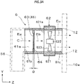
- the mesh plate 65 as the vent plate which is an example of the collecting portion 63, is disposed in the vent pipe 61 at a position on an upstream side of the air flow generating portion 62 in the direction C in which the air in the flow path space 61a of the vent pipe 61 is sent.
- the capturing device 6 operates at least during a period in which the fixing device 5 is operating or during a predetermined period after the fixing device 5 is stopped.
- the air flow generating portion 62 is started, and an air flow flowing in a direction indicated by an arrow C is generated in the flow path space 61a of the vent pipe 61.
- the air containing the fine particles mainly generated in the fixing operation in the fixing device 5 is suctioned and flows into the flow path space 61a of the vent pipe 61 through the collecting duct 56.
- an air Ea before collection which contains the fine particles and flowed in at this time, substantially collides with the mesh plate 65 as the vent plate which is an example of the collecting portion 63, passes through the mesh opening 66 which is the vent portion 63a of the mesh plate 65, and moves as an air Eb after collection.
- the air Ea before collection passes through the mesh plate 65 having the plural mesh openings 66 with the opening size of 0.005 mm or more and 0.1 mm or less while colliding with the mesh plate 65. Accordingly, ultrafine particles having a particle diameter of 100 nm or less are likely to adhere to the wire rods of the mesh plate 65 when colliding with the mesh plate 65, and as a result, a total amount of the ultrafine particles among the fine particles contained in the passing air is reduced.
- the air Eb after collection passes through the air flow generating portion 62, and is discharged to the outside from the exhaust port 12 of the housing 10 of the image forming device 1 as a final exhaust air Ec.
- the final exhaust air Ec is air in which a total amount of ultrafine particles is reduced as compared with the air Ea before collection.
- the reduction of the total amount of ultrafine particles means that a total amount of ultrafine particles in a case where the mesh plate 65 as the vent plate is provided as the collecting portion 63 is smaller than a total amount of ultrafine particles in a case where the mesh plate 65 as the vent plate is not provided.
- the total amount of ultrafine particles is preferably reduced by 30% or more with respect to the total amount of ultrafine particles in the case where the mesh plate 65 is not provided.
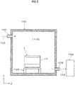
- the test T1 relating to the collecting effect at this time is a test performed in accordance with a test standard (RAL-UZ205) of Blue Angel Mark, which is a German environment label.
- the test T1 was performed by placing and equilibrating the image forming device 1 to be measured on a mounting table 120 in a space 110 of a test chamber 100 set to a predetermined room environment (temperature: 23°C, humidity: 50% RH) with high airtightness, which is a test environment room, activating the image forming device 1, performing a predetermined image forming operation for 10 minutes (600 s), and measuring, by a measuring device (manufactured by TSI Corporation: condensed particle counter CPC Model 3775) 150, an amount of ultrafine particles (UFPs) or the like contained in a room air during the image forming operation and within a predetermined time after the operation is stopped.
- a measuring device manufactured by TSI Corporation: condensed particle counter CPC Model 3775
- the test chamber 100 has a room having a volume of, for example, 5.1 m 3 , and a clean air 132 is supplied into the room from an air supply port 103, and the room air 133 is exhausted from an exhaust port 104.
- the room air 133 exhausted from the test chamber 100 is communicated with and sent to the measuring device 150.
- the image forming device 1 to be measured was applied in which the mesh plate 65 having the following configuration of the collecting portion 63 of the capturing device 6 is disposed.
- the image forming device 1 as a comparison reference was also prepared in which the mesh plate 65 as the vent plate of the collecting portion 63 of the capturing device 6 is not disposed.
- the total area of the portions of the mesh plate 65 to be brought into contact with the air was 14,400 mm 2 .
- a mesh plate (a metal mesh plate) formed by plain weaving wire rods made of stainless steel (SUS), and having a size of the mesh opening 66 of 0.22 mm, an opening ratio of 40%, and a thickness D of 0.026 mm was used.
- the axial fan which is the air flow generating portion 62, was operated to generate an air flow having an air volume of 0.33 m 3 /min. Further, the capturing device 6 was operated during a period from the start to the stop of the image forming operation in the test.
- a mesh plate (a PET mesh plate) formed by plain weaving wire rods made of PET was prepared, and the capturing device 6 to which the mesh plate is attached was also used.
- An image formed by the image forming operation is a chart designated by BA (Blue Angel) having an image area ratio of 5%.
- the "#" in a unit of a vertical axis of a graph in Fig. 6 indicates the number of UFPs.
- the total amount of UFPs is gradually reduced after the image forming operation is stopped, as in the case of the image forming device as the comparison reference, but at this time, the total amount is also transitioned in the reduced amount as compared with the total amount in the image forming device as the comparison reference.
- a UFP value was determined based on the method described in the test standard (RAL-UZ205).
- the UFP reduction rate was determined based on a difference between presence and absence of the mesh plate 65.
- test T1 was also performed in the same manner with a PET mesh plate as the mesh plate 65.
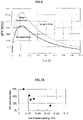
- metal mesh plates 65 Five types were prepared each having opening sizes of 0.01 mm, 0.022 mm, 0.025 mm, 0.032 mm, and 0.067 mm as shown on a horizontal axis of Fig. 7A .
- One type of PET mesh plate was prepared having an opening size of 0.086 mm as shown on a horizontal axis of Fig. 7B .
- both the metal mesh plate 65 and the PET mesh plate were adjusted such that all opening ratios are maintained at about 40% even when the size of the mesh opening 66 is changed.
- the opening size and the UFP reduction rate are substantially inversely proportional to each other. From this result, it can be said that when the size of the mesh opening is in a range of 0.01 mm or more and 0.07 mm or less (about 0.08 mm or less), the effect of reducing the UFPs can be obtained.
- a test T2 was performed to examine a relationship between an opening ratio of the mesh opening 66 of the mesh plate 65 of the capturing device 6 and a pressure loss. Results of the test T2 are shown in Fig. 8 .
- a metal mesh plate alone was prepared as the mesh plate 65.
- Five types of metal mesh plates 65 were prepared each having opening ratios of 11%, 13%, 40%, 49.5%, and 60% as shown on a horizontal axis of Fig. 8 .
- an amount of air passing through the mesh plate 65 is likely to be limited, and thus, for example, the air suctioned from the fixing device 5 is less likely to be exhausted, and the air heated to a high temperature by the fixing operation is likely to remain in the housing 50 of the fixing device 5 or the housing 10 of the image forming device 1, so that a temperature inside the apparatus is likely to rise.
- a load may be likely to be applied to the driving of the air flow generating portion 62 or the like, or noise may be likely to be generated.
- the pressure loss is preferably set to 40 Pa or less. From the results shown in Fig. 8 , it can be said that the opening ratio of the mesh plate 65 is desirably 30% or more in order to obtain the preferable pressure loss.
- the thickness D of the mesh plate 65 which is the vent plate, is 5 mm or less, and thus the dimension of the disposition space in which the mesh plate 65 is disposed can be reduced in the direction C in which the air passes, and for example, a size of the disposition space of the mesh plate 65 can be reduced, which can contribute to miniaturization of the capturing device 6 and the image forming device 1 equipped with the capturing device 6.
- the size of the disposition space can be reduced, which is advantageous.
- the mesh plate 65 is disposed at the position on the upstream side of the air flow generating portion 62 in the direction C in which the air is sent, the air collected from the fixing device 5 and introduced into the vent pipe 61 first comes into contact with the mesh plate 65 and passes through the mesh plate 65, and the total amount of ultrafine particles is reliably reduced as compared with a case where the mesh plate 65 is disposed at a position on a downstream side of the air flow generating portion 62.
- the capturing device 6 it is confirmed that deterioration in a collecting performance of the mesh plate 65 due to clogging of the mesh opening 66 or the like is less likely to occur. Therefore, the capturing device 6 has an advantage that replacement of the mesh plate 65 is substantially unnecessary, and as a result, the running cost can be reduced, and the maintenance work can be reduced as compared with other types of collecting portions that require regular replacement.
- Fig. 9A shows a particulate capturing device according to a second exemplary embodiment of the present invention.
- the particulate capturing device 6 according to the second exemplary embodiment has the same configuration as that of the capturing device 6 according to the first exemplary embodiment except that the vent plate of the collecting portion 63 is changed by applying a porous plate 67 instead of the mesh plate 65.
- Fig. 9B is a schematic diagram showing a configuration of the porous plate 67 which is the collecting portion of the capturing device in Fig. 9A .
- the porous plate 67 is formed of a porous plate having a thickness D of 5 mm or less and having plural vent holes 68 with an opening size of 0.005 mm or more and 0.1 mm or less.
- the porous plate 67 is a plate-shaped member in which the plural vent holes 68 having the same opening shape are provided so as to be substantially evenly scattered.
- an opening size of the vent hole 68 of the porous plate 67 is set to a value obtained by averaging diameters R of all the vent holes 68, as shown in Fig. 10 .
- an equivalent circle diameter of the opening is defined as the opening size.
- the meaning of a range (0.005 mm or more and 0.1 mm or less) of the opening size of the vent hole 68 as the vent portion 63a of the porous plate 67 which is another example of the vent plate, the meaning of the thickness D of the porous plate 67, and the like are the same as those in the case of the mesh plate 65 in the first exemplary embodiment described above.
- the vent plate (the porous plate 67) has an opening ratio of 20% or more and 60% or less as in the case of the mesh plate 65 in the first exemplary embodiment.
- the opening ratio of the porous plate 67 in Fig. 9B indicates, in percentage, a ratio of a total opening area of the vent holes 68 to the flow path area of the vent pipe 61.
- the porous plate 67 is also manufactured by using a material made of a metal or a material made of a synthetic resin. More specifically, a porous plate is obtained by subjecting a plate material made of the material to a predetermined drilling process.
- the capturing device 6 to which the porous plate 67 is applied also operates substantially in the same manner as in the case of the capturing device 6 according to the first exemplary embodiment.
- the air Ea before collection which contains the fine particles and flowed into the flow path space 61a of the vent pipe 61 by the operation of the air flow generating portion 62, substantially collides with the porous plate 67 as the vent plate which is an example of the collecting portion 63, passes through the vent hole 68 which is the vent portion 63a of the porous plate 67, and moves as the air Eb after collection.
- the air Ea before collection passes through the porous plate 67 having the plural vent holes 68 with the opening size of 0.005 mm or more and 0.1 mm or less. Accordingly, ultrafine particles having a particle diameter of 100 nm or less are likely to adhere to non-ventilation portions and the like of the porous plate 67 when colliding with the porous plate 67, and as a result, a total amount of the ultrafine particles among the fine particles contained in the passing air is reduced.
- the air Eb after collection passes through the air flow generating portion 62, and is discharged to the outside from the exhaust port 12 of the housing 10 of the image forming device 1 as the final exhaust air Ec.
- the final exhaust air Ec is air in which a total amount of ultrafine particles is reduced as compared with the air Ea before collection.
- test T1 relating to a collecting effect of the capturing device 6 will be described.
- test T1 was also performed in the same manner with a PET porous plate made of PET.
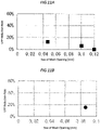
- porous metal plates (so-called punching metal) 67 were prepared each having opening sizes of 0.047 mm, 0.10 mm, and 0.12 mm as shown on a horizontal axis of Fig. 11A .
- a PET porous plate was prepared having an opening size of 0.086 mm as shown on a horizontal axis of Fig. 11B .
- both the porous metal plate 67 and the PET porous plate were adjusted such that all opening ratios are maintained at about 40% even when the opening size of the vent hole 68 is changed.
- the opening size and the UFP reduction rate are substantially inversely proportional to each other. From this result, it can be said that in the porous metal plate 67, when the opening size is in a range of 0.04 mm or more and 0.01 mm or less, an effect of reducing UFPs can be obtained.
- results at this time are substantially the same as the results ( Fig. 8 ) of the test T1 in the first exemplary embodiment.
- the present invention is not limited to the contents exemplified in the first and second exemplary embodiments, and can be modified in various ways, and includes, for example, modifications as listed below.
- the capturing device 6 in which the vent plate of the collecting portion 63 is disposed at the position on the upstream side of the air flow generating portion 62 in the direction C in which the air is sent has been exemplified, but in the capturing device 6, the vent plate of the collecting portion 63 may be disposed at the position on the downstream side of the air flow generating portion 62 in the direction C.
- the particulate capturing device 6 is applied as a capturing device that collects fine particles containing ultrafine particles generated in the fixing device 5 of the image forming device 1 has been exemplified, but a capturing device that collects ultrafine particles may be provided in an exhaust portion that collects and exhausts air containing fine particles generated in a constituent portion other than the fixing device 5 of the image forming device 1.
- the capturing device 6 according to the present invention may be applied to various devices other than an image forming device as long as ultrafine particles need to be collected.
- an image forming device to which the particulate capturing device 6 is applied is not limited to the image forming device 1 of the type exemplified in the first exemplary embodiment, and may be an image forming device of another type using an electrophotographic method (including a type of forming a multicolor image). Further, the image forming device to which the capturing device 6 is applied may be an image forming device adopting an image forming method (for example, a liquid droplet ejecting method, a printing method, or the like) other than the electrophotographic method.
Landscapes
- Chemical Kinetics & Catalysis (AREA)
- Chemical & Material Sciences (AREA)
- Physics & Mathematics (AREA)
- General Physics & Mathematics (AREA)
- Biodiversity & Conservation Biology (AREA)
- Environmental & Geological Engineering (AREA)
- Environmental Sciences (AREA)
- Ecology (AREA)
- Life Sciences & Earth Sciences (AREA)
- Atmospheric Sciences (AREA)
- Engineering & Computer Science (AREA)
- Control Or Security For Electrophotography (AREA)
- Fixing For Electrophotography (AREA)
- Electrophotography Configuration And Component (AREA)
Abstract
Description
- The present invention relates to a particulate capturing device and an image forming device.
-
Patent Literature 1 describes an optional device for an electric device, the optional device including a duct for merging exhaust gases from plural exhaust ports of an electric device and discharging the exhaust gases from one outlet into the atmosphere, a filter and an electric fan built in front of the outlet of the duct, an air flow sensor that detects presence or absence of an exhaust gas from one of the plural exhaust ports, and a control device that controls an operation of the electric fan based on an output of the air flow sensor, in which the air flow sensor is disposed at an exhaust port having a highest exhaust gas velocity among the plural exhaust ports.Patent Literature 1 also describes an image forming device including the optional device. -
Patent Literature 2 describes an air filter disposed in a flow path of air suctioned from a fixing device of an image forming device, the air filter including a porous body that is a powder of a metal organic framework or a porous coordination polymer, and a support body that supports the porous body, in which the porous body has an average pore diameter of 5 angstroms or more and less than 22 angstroms. - Patent Literature 3 describes a filter unit for a copying machine, the filter unit being mounted in a copying machine and removing ultrafine particles (UFPs) in air as exhaust gas generated when a toner image is heated and fixed to paper, in which a filter medium of the filter unit is pleated and accommodated in a frame, the filter medium includes a liquid-charged nonwoven fabric layer, a ratio S1/S2 obtained by dividing a total filter medium area S1 of the filter medium by an opening area S2 of the filter unit is 7 or more, and a UFP removal efficiency calculated based on particle emissions of the filter unit is 90% or more.
-
Patent Literature 4 describes an exhaust gas purifying filter used in a method for collecting a particulate material in exhaust gas, in which a wall-through type filter is disposed at a front stage along a direction in which the exhaust gas flows, a filter in which a needle-shaped material or a fiber is formed at a wall surface portion contacting with the exhaust gas is disposed at a rear stage, the needle-shaped material is a needle-shaped cordierite crystal grown from a thin wall of a cordierite honeycomb, and the fiber is a silicon carbide fiber or a ceramic fiber nonwoven fabric. -
Patent Literature 5 describes a duct removing device for an electric dust collector in which a punching metal is attached to a downstream side of a dust collecting electrode.Patent Literature 5 also discloses that an opening ratio of the punching metal is set to 20% to 60%, and an opening diameter of the punching metal is set to 2 mm to 10 mm. -
Patent Literatures -
- Patent Literature 1:
Japanese Patent No. 6536082 claims Fig. 6 , etc.) - Patent Literature 2:
JP-A-2017-198884 claim 1,Figs. 1 and2 , etc.) - Patent Literature 3:
JP-A-2018-4774 claim 1,Figs. 1 and2 , etc.) - Patent Literature 4:
Japanese Patent No. 4649587 claim 1,Fig. 1 , etc.) - Patent Literature 5:
JP-A-2002-239413 claims Fig. 1 , etc.) - Patent Literature 6:
JP-A-H09-173897 claim 1,Figs. 1 and2 , etc.) - Patent Literature 7:
JP-A-2002-239413 claim 1,Fig. 1 , etc.) - The present invention is to provide a particulate capturing device and an image forming device using the capturing device, which can reduce a total amount of ultrafine particles having a particle diameter of 100 nm or less contained in air with a small pressure loss even a thickness of a collecting portion is thin in a direction in which air passes, as compared with a case where a vent plate having a thickness of 5 mm or less and having plural vent portions with an opening size of 0.005 mm or more and 0.1 mm or less is not applied as the collecting portion.
- A particulate capturing device according to a first aspect of the present invention includes:
- a vent pipe having a flow path space through which air containing fine particles flows;
- an air flow generating portion configured to generate an air flow flowing in a direction in which the air is to be sent in the flow path space of the vent pipe; and
- a collecting portion disposed in a state of crossing the flow path space of the vent pipe in a direction intersecting the air flow, and configured to collect the fine particles contained in the air, in which
- the collecting portion is formed of a vent plate having a thickness of 5 mm or less and having a plurality of vent portions with an opening size of 0.005 mm or more and 0.1 mm or less.
- A particulate capturing device according to a second aspect of the present invention is the capturing device according to the first aspect, in which the vent plate has an opening ratio of 20% or more and 60% or less.
- A particulate capturing device according to a third aspect of the present invention is the capturing device according to the first aspect or the second aspect, in which the vent plate is formed of a mesh plate.
- A particulate capturing device according to a fourth aspect of the present invention is the capturing device according to the first aspect or the second aspect, in which the vent plate is formed of a porous plate.
- A particulate capturing device according to a fifth aspect of the present invention is the capturing device according to any one of the first to fourth aspects, in which the vent plate is disposed on an upstream side of the air flow generating portion in a direction in which the air is sent.
- An image forming device according to a sixth aspect of the present invention including:
- an exhaust portion configured to collect and exhaust air existing in an apparatus main body, in which
- the exhaust portion includes the particulate capturing device according to any one of the first to fourth aspects.
- An image forming device according to a seventh aspect of the present invention is the image forming device according to the sixth aspect, further including a fixing portion configured to thermally fix an unfixed toner image to a recording medium, in which the exhaust portion includes a suction port configured to collect air existing in the fixing portion, and an exhaust port configured to exhaust the collected air to the outside.
- According to the particulate capturing device in the first aspect, a total amount of ultrafine particles having a particle diameter of 100 nm or less contained in air in the collecting portion can be reduced with a small pressure loss even a thickness is thin in a direction in which air passes, as compared with a case where the vent plate having the thickness of 5 mm or less and having the plurality of vent portions with the opening size of 0.005 mm or more and 0.1 mm or less is not applied as the collecting portion.
- According to the second aspect, the total amount of ultrafine particles can be reduced while maintaining a small pressure loss, as compared with a case where the vent plate does not have the opening ratio of 20% or more and 60% or less.
- According to the third aspect, it is easier to manufacture a vent plate having vent portions with an opening of a required size, as compared with a case where the vent plate is not formed of the mesh plate.
- According to the fourth aspect, it is easier to adjust an opening size of a vent plate having vent portions with an opening of a required pattern, as compared with a case where the vent plate is not formed of the porous plate.
- According to the fifth aspect, the total amount of ultrafine particles contained in the air can be reduced more reliably, as compared with a case where the vent plate is not disposed on the upstream side of the air flow generating portion in the direction in which the air is sent.
- According to the image forming device in the sixth aspect, a total amount of ultrafine particles having a particle diameter of 100 nm or less contained in air in the apparatus main body can be reduced with a small pressure loss even a thickness is thin in a direction in which air passes, as compared with a case where a capturing device to which the collecting portion formed of the vent plate having the thickness of 5 mm or less and having the plurality of vent portions with the opening size of 0.005 mm or more and 0.1 mm or less is applied is not disposed as the capturing device.
- According to the seventh aspect, from air containing ultrafine particles generated in the fixing portion, a total amount of the ultrafine particles can be reduced.
-
-
Fig. 1 is a schematic diagram showing an entire image forming device according to a first exemplary embodiment. -
Fig. 2 is a schematic diagram showing a configuration of a fixing device and a particulate capturing device, which are parts of the image forming device inFig. 1 . -
Fig. 3A is a schematic diagram showing the particulate capturing device inFig. 2 . -
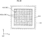
Fig. 3B is a schematic diagram showing a configuration of a mesh plate which is a collecting portion of the capturing device inFig. 3A . -
Fig. 4 shows a schematic diagram and an enlarged view showing the configuration of the mesh plate inFig. 3B and a part thereof. -
Fig. 5 is a cross-sectional schematic diagram showing test contents adopted in a test T1 or the like. -
Fig. 6 is a graph showing results of examining an effect of reducing a total amount of ultrafine particles by the capturing device in the test T1. -
Fig. 7A is a graph showing results of examining a relationship between a size of a mesh opening of a metal mesh plate and an ultrafine particle reduction rate. -
Fig. 7B is a graph showing a result of examining a relationship between a size of a mesh opening of a PET mesh plate and an ultrafine particle reduction rate. -
Fig. 8 is a graph showing results of a test T2 in which a relationship between an opening ratio of a metal mesh plate and a pressure loss is examined. -
Fig. 9A is a schematic diagram showing a particulate capturing device according to a second exemplary embodiment. -
Fig. 9B is a schematic diagram showing a configuration of a porous plate which is a collecting portion of the capturing device inFig. 9A . -
Fig. 10 is a schematic diagram showing the configuration of the porous plate inFig. 9B . -
Fig. 11A is a graph showing results of examining a relationship between an opening size of a porous metal plate and an ultrafine particle reduction rate. -
Fig. 11B is a graph showing a result of examining a relationship between an opening size of a PET porous plate and an ultrafine particle reduction rate. - Hereinafter, embodiments of the present invention will be described with reference to the drawings.
-
Figs. 1 and2 show a particulate capturing device and an image forming device according to a first exemplary embodiment of the present invention.Fig. 1 shows an overall configuration of the image forming device, andFig. 2 shows a configuration of a part of the image forming device (mainly a fixing device, and an exhaust portion including the particulate capturing device). - Arrows denoted by reference signs X, Y, and Z in each drawing such as
Fig. 1 indicate directions of a width, a height, and a depth of a three-dimensional space assumed in the drawing. In addition, in the drawing, a circle at an intersection of arrows in X and Y directions indicates that a Z direction is directed vertically downward in the drawing. - An
image forming device 1 shown inFig. 1 is an apparatus that forms an image on asheet 9, which is an example of a recording medium, by an electrophotographic method. Theimage forming device 1 according to the first exemplary embodiment is, for example, a printer that forms an image corresponding to image information input from an externally connected device such as an information terminal. - As shown in
Fig. 1 , theimage forming device 1 includes ahousing 10 having a required external shape, and includes, in an internal space of thehousing 10, animage forming device 2 that forms a toner image formed of a toner as a developer based on image information and transfers the toner image to thesheet 9, asheet feeding device 4 that accommodates and feeds thesheet 9 to be supplied to a position where theimage forming device 2 performs the transfer, a fixingdevice 5 which is an example of a fixing portion fixing the toner image transferred by theimage forming device 2 to thesheet 9, aparticulate capturing device 6 that collects fine particles generated in thefixing device 5 and a periphery thereof, and the like. - Here, the image information is, for example, information related to an image such as a character, a figure, a photograph, or a pattern. The
housing 10 is a structure formed into a required shape by various support members, exterior materials, and the like. A dashed-dotted line with an arrow inFig. 1 and the like indicates a main transport path when thesheet 9 is transported in thehousing 10. - The
image forming device 2 includes aphotoconductive drum 21 which is an example of an image carrier rotating in a direction indicated by an arrow A, and includes devices such as a chargingdevice 22, anexposure device 23, a developingdevice 24, atransfer device 25, and acleaning device 26 which are arranged around thephotoconductive drum 21. - The charging
device 22 is a device that charges an outer peripheral surface (an image formable surface) of thephotoconductive drum 21 to a required surface potential. The chargingdevice 22 includes, for example, a charging member such as a roller which is brought into contact with an image forming region of the outer peripheral surface of thephotoconductive drum 21 and to which a charging current is supplied. Theexposure device 23 is a device that exposes the charged outer peripheral surface of thephotoconductive drum 21 based on the image information to form an electrostatic latent image. Theexposure device 23 operates in response to reception of an image signal generated by performing required processing, by an image processor (not shown) or the like, on the image information input from the outside. - The developing
device 24 is a device that develops the electrostatic latent image formed on the outer peripheral surface of thephotoconductive drum 21 with a corresponding developer (toner) of a predetermined color (for example, black) to visualize the electrostatic latent image as a monochrome toner image. Thetransfer device 25 is a device that electrostatically transfers the toner image formed on the outer peripheral surface of thephotoconductive drum 21 to thesheet 9. Thetransfer device 25 includes a transfer member such as a roller which is brought into contact with the outer peripheral surface of thephotoconductive drum 21 and to which a transfer current is supplied. Thecleaning device 26 is a device that cleans the outer peripheral surface of thephotoconductive drum 21 by scraping off and removing unnecessary substances such as unnecessary toner and paper dust adhering to the outer peripheral surface of thephotoconductive drum 21. - In the
image forming device 2, each portion where thephotoconductive drum 21 and thetransfer device 25 face each other is a transfer position TP where the toner image is transferred. - The
sheet feeding device 4 is a device configured to accommodate and feed thesheet 9 to be supplied to the transfer position TP in theimage forming device 2. Thesheet feeding device 4 includes devices such as anaccommodating body 41 that accommodates thesheet 9, and afeeding device 43 that feeds thesheet 9. - The
accommodating body 41 is an accommodating member that includes a loading plate (not shown) loading and accommodating theplural sheets 9 in a required orientation, and is attached so as to be pulled out to the outside of thehousing 10 for performing an operation such as replenishment of thesheets 9. Thefeeding device 43 is a device that feeds thesheets 9 loaded on the loading plate of theaccommodating body 41 one by one by a feed device such as plural rollers. - The
sheet 9 may be any recording medium, such as plain paper, coated paper, or thick paper, which can be transported in thehousing 10 and to which a toner image can be transferred and fixed, and a material, a form, and the like thereof are not particularly limited. - The fixing
device 5 is a device configured to fix the toner image transferred at the transfer position TP of theimage forming device 2 to thesheet 9. The fixingdevice 5 includes devices such as aheating rotating body 51 and a pressingrotating body 52 in an internal space of ahousing 50 in which anintroduction port 50a and adischarge port 50b for thesheet 9 are provided. - The
heating rotating body 51 is a rotating body having a roller form, a belt-pad form, or the like that rotates in a direction indicated by an arrow, and is heated by a heating portion (not shown) such that an outer surface of theheating rotating body 51 is maintained at a required temperature. The pressingrotating body 52 is a rotating body having a roller form, a belt-pad form, or the like that rotates so as to contact and follow theheating rotating body 51 under a required pressure. As the pressingrotating body 52, a rotating body heated by the heating portion may be applied. - In the
fixing device 5, a portion where theheating rotating body 51 and the pressingrotating body 52 come into contact with each other is a nip portion (a fixing processing portion) FN that performs processing such as heating and pressing for fixing an unfixed toner image to thesheet 9. - A portion indicated by the dashed-dotted line denoted by a reference sign Rt1 in
Fig. 1 is a sheet feeding transport path for transporting and supplying thesheet 9 in thesheet feeding device 4 to the transfer position TP. The sheet feeding transport path Rt1 includesplural transport rollers sheet 9, plural guide members (not shown) that secure a transport space for thesheet 9 and guide the transport of thesheet 9, and the like. - In the
image forming device 1, when a controller (not shown) receives a command of an operation of forming an image, a charging operation, an exposure operation, a developing operation, and a transfer operation are executed in theimage forming device 2, and on the other hand, a sheet feeding operation of thesheet 9 from thesheet feeding device 4 to the transfer position TP is executed. Accordingly, after a toner image is formed on thephotoconductive drum 21, the toner image is transferred to thesheet 9 supplied from thesheet feeding device 4 to the transfer position TP. - Subsequently, in the
image forming device 1, in thefixing device 5, thesheet 9 to which the toner image is transferred is introduced into the nip portion FN, and a fixing operation is performed. Accordingly, an unfixed toner image is fixed to thesheet 9. Thesheet 9 after the fixing is discharged and accommodated in an accommodating portion (not shown) outside thehousing 10 by, for example, adischarge roller 45. - As a result, an image forming operation on one side of one
sheet 9 by theimage forming device 1 is completed. - The
image forming device 1 includes the exhaust portion that collects and exhausts air existing in an apparatus main body. As shown inFigs. 1 to 3A and the like, the exhaust portion includes a collectingduct 56, theparticulate capturing device 6, and anexhaust port 12. In an example shown inFigs. 1 to 3A and the like, the exhaust portion that collects and exhausts air existing in thefixing device 5 is provided. - Next, as shown in
Figs. 1 to 3B and the like, theparticulate capturing device 6 includes avent pipe 61, an airflow generating portion 62, a collectingportion 63, and the like. - A particle diameter of fine particles collected by the
capturing device 6 is 100 µm or less. An example of the fine particles is so-called ultrafine particles (UFPs) having a particle diameter of 100 nm (0.1 µm) or less. Here, the particle diameter is a spherical equivalent volume diameter. - An example of the ultrafine particles to be collected by the
capturing device 6 is, for example, ultrafine particles contained in fine particles (dust) generated by cooling after a component such as wax contained in a toner is volatilized by heating during fixing processing (the fixing operation). - The
vent pipe 61 is a tubular structure having aflow path space 61a through which air containing fine particles flows. - The
vent pipe 61 in the first exemplary embodiment is a rectangular tubular pipe having a substantially rectangular cross-sectional shape in a direction intersecting an air flow of theflow path space 61a. As shown inFigs. 2 and3A , oneend portion 61b of thevent pipe 61 is connected to the collectingduct 56 provided on a side surface portion of thehousing 50 of the fixingdevice 5, and theother end portion 61c of thevent pipe 61 is connected to theexhaust port 12 provided on aback surface portion 10e of thehousing 10. The collectingduct 56 collects and takes in air existing in or around thehousing 50 of the fixingdevice 5 from thesuction port 56a provided at a position higher than theintroduction port 50a and thedischarge port 50b in thehousing 50. Theexhaust port 12 and the collectingduct 56 are parts of the exhaust portion. - The air
flow generating portion 62 generates an air flow for flowing in a direction C in which the air is to be sent in theflow path space 61a of thevent pipe 61. - In the first exemplary embodiment, an axial fan is applied as the air
flow generating portion 62. As shown inFig. 3A , the axial fan includes, for example, aframe portion 621 in which a throughportion 621a having a circular cross section is formed, ashaft portion 622 that exists in the throughportion 621a of theframe portion 621 and is rotatably supported, and includes a built-in driving motor, andplural blade portions 623 erected around theshaft portion 622. - An intensity (air volume or air velocity) of the air flow generated by the air
flow generating portion 62 is preferably set in a range of 0.1 m3/min to 1 m3/min from the viewpoint of preventing an increase in temperature or dew condensation in thehousing 10 of the image forming device 1 (particularly in thehousing 50 of the fixingdevice 5 in the present example) and the like. - The collecting
portion 63 is disposed in a state of crossing theflow path space 61a in a middle portion of thevent pipe 61 in a direction intersecting the air flow, and collects fine particles contained in the air flowing through theflow path space 61a. - As shown in
Fig. 3B and the like, the collectingportion 63 in the first exemplary embodiment is formed of a vent plate having a thickness D of 5 mm or less and havingplural vent portions 63a with an opening size of 0.005 mm or more and 0.1 mm or less inside anouter frame 64, and specifically, as shown inFig. 4 , the collectingportion 63 is formed of amesh plate 65 having a thickness D of 5 mm or less and having plural meshes (mesh openings) 66 with an opening size of 0.005 mm or more and 0.1 mm or less. - Here, the
vent portion 63a is a gap penetrating themesh plate 65 inside theouter frame 64. When openings have a rectangular shape, the opening size of thevent portion 63a is a value obtained by averaging vertical and horizontal dimensions of the openings of all thevent portions 63a in the vent plate of a size when actually mounted and used (a flow path area of a portion disposed in theflow path space 61a). As shown inFig. 3A , the thickness D of the vent plate is a dimension along the direction C in which the air passes through thevent portion 63a. - As shown in
Fig. 4 , themesh plate 65, which is an example of the vent plate, is a mesh-shaped member in which the plural meshes (mesh openings) 66 having substantially the same opening shape are provided to be substantially evenly scattered. More specifically, themesh plate 65 is a mesh-shaped member formed by weaving alongitudinal wire rod 65a and atransverse wire rod 65b by a weaving method such as plain weaving to form the plural meshes (mesh openings) 66. When a mesh plate provided with theplural mesh openings 66 having a rectangular opening shape is used as themesh plate 65, the size of themesh opening 66 is a value obtained by averaging vertical widths Ma and horizontal widths Mb of all themesh openings 66, as shown inFig. 4 . - The
wire rods mesh plate 65 preferably have a wire diameter in a range of 0.01 mm to 0.06 mm from the viewpoint of keeping the opening size or an opening ratio described later within a required range and the like. - When the opening size of the
vent portion 63a (the mesh opening 66) of the vent plate (the mesh plate 65) is less than 0.005 mm, there are problems such as difficulty in manufacturing the vent plate (the mesh plate 65) having thevent portions 63a (the mesh openings 66) of the size, and an excessive pressure loss. In contrast, when the opening size is larger than 0.1 mm, an effect of reducing the UFPs contained in the air is particularly difficult or impossible to obtain. - When the thickness D of the vent plate (the mesh plate 65) is more than 5 mm, a dimension of a disposition space in which the vent plate is disposed increases in a direction in which the air passes. The thickness D is preferably 4 mm or less, and more preferably 2 mm or less. Incidentally, a lower limit value of the thickness D is not particularly limited as long as the
mesh plate 65 can be manufactured and a required collecting performance (particularly, an effect of reducing a total amount of UFPs) can be obtained, and when the lower limit value is, for example, 0.02 mm, there is no particular problem. - The vent plate (the mesh plate 65) has an opening ratio of 20% or more and 60% or less.
- The opening ratio indicates, in percentage, a ratio of a total opening area of all the
vent portions 63a (all the mesh openings 66) to a total area of portions where the vent plate (the mesh plate 65) actually comes into contact with the air in theflow path space 61a of thevent pipe 61. Specifically, the opening ratio of themesh plate 65 inFig. 3B indicates, in percentage, a ratio of the total opening area of themesh openings 66 to a flow path area of thevent pipe 61. When the opening ratio is less than 20%, there are problems that a pressure loss increases, the air is difficult to flow, and the like. In contrast, when the opening ratio is more than 60%, the effect of reducing the UFPs contained in the air cannot be particularly obtained. - The opening ratio is more preferably 25% or more and 40% or less from the viewpoints of, for example, reliably reducing the pressure loss and reliably obtaining the effect of reducing a total amount of fine particles of 100 µm or less contained in the air.
- The
mesh plate 65 may be manufactured by using, for example, a wire rod made of a metal such as stainless steel or aluminum. Themesh plate 65 may be manufactured by using a wire rod made of a synthetic resin such as polyethylene terephthalate (PET), acrylonitrile butadiene styrene copolymer resin (ABS resin), or polyvinyl chloride. - In the
capturing device 6, as shown inFigs. 2 and3A , themesh plate 65 as the vent plate, which is an example of the collectingportion 63, is disposed in thevent pipe 61 at a position on an upstream side of the airflow generating portion 62 in the direction C in which the air in theflow path space 61a of thevent pipe 61 is sent. - The
capturing device 6 operates at least during a period in which thefixing device 5 is operating or during a predetermined period after thefixing device 5 is stopped. - That is, when an operation time of the
capturing device 6 is reached, the airflow generating portion 62 is started, and an air flow flowing in a direction indicated by an arrow C is generated in theflow path space 61a of thevent pipe 61. - Accordingly, the air containing the fine particles mainly generated in the fixing operation in the
fixing device 5 is suctioned and flows into theflow path space 61a of thevent pipe 61 through the collectingduct 56. - As shown in
Fig. 3A , an air Ea before collection, which contains the fine particles and flowed in at this time, substantially collides with themesh plate 65 as the vent plate which is an example of the collectingportion 63, passes through themesh opening 66 which is thevent portion 63a of themesh plate 65, and moves as an air Eb after collection. - At this time, the air Ea before collection passes through the
mesh plate 65 having theplural mesh openings 66 with the opening size of 0.005 mm or more and 0.1 mm or less while colliding with themesh plate 65. Accordingly, ultrafine particles having a particle diameter of 100 nm or less are likely to adhere to the wire rods of themesh plate 65 when colliding with themesh plate 65, and as a result, a total amount of the ultrafine particles among the fine particles contained in the passing air is reduced. - The air Eb after collection passes through the air
flow generating portion 62, and is discharged to the outside from theexhaust port 12 of thehousing 10 of theimage forming device 1 as a final exhaust air Ec. - The final exhaust air Ec is air in which a total amount of ultrafine particles is reduced as compared with the air Ea before collection.
- The reduction of the total amount of ultrafine particles means that a total amount of ultrafine particles in a case where the
mesh plate 65 as the vent plate is provided as the collectingportion 63 is smaller than a total amount of ultrafine particles in a case where themesh plate 65 as the vent plate is not provided. - The total amount of ultrafine particles is preferably reduced by 30% or more with respect to the total amount of ultrafine particles in the case where the
mesh plate 65 is not provided. - Next, a test T1 relating to a collecting effect of the
capturing device 6 will be described. - The test T1 relating to the collecting effect at this time is a test performed in accordance with a test standard (RAL-UZ205) of Blue Angel Mark, which is a German environment label.
- As shown in
Fig. 5 , the test T1 was performed by placing and equilibrating theimage forming device 1 to be measured on a mounting table 120 in aspace 110 of atest chamber 100 set to a predetermined room environment (temperature: 23°C, humidity: 50% RH) with high airtightness, which is a test environment room, activating theimage forming device 1, performing a predetermined image forming operation for 10 minutes (600 s), and measuring, by a measuring device (manufactured by TSI Corporation: condensed particle counter CPC Model 3775) 150, an amount of ultrafine particles (UFPs) or the like contained in a room air during the image forming operation and within a predetermined time after the operation is stopped. - The
test chamber 100 has a room having a volume of, for example, 5.1 m3, and aclean air 132 is supplied into the room from anair supply port 103, and theroom air 133 is exhausted from anexhaust port 104. Theroom air 133 exhausted from thetest chamber 100 is communicated with and sent to themeasuring device 150. - The
image forming device 1 to be measured was applied in which themesh plate 65 having the following configuration of the collectingportion 63 of thecapturing device 6 is disposed. Theimage forming device 1 as a comparison reference was also prepared in which themesh plate 65 as the vent plate of the collectingportion 63 of thecapturing device 6 is not disposed. - In the
capturing device 6, the total area of the portions of themesh plate 65 to be brought into contact with the air (the flow path area of the vent pipe 61) was 14,400 mm2. - As the
mesh plate 65 of thecapturing device 6, a mesh plate (a metal mesh plate) formed by plain weaving wire rods made of stainless steel (SUS), and having a size of themesh opening 66 of 0.22 mm, an opening ratio of 40%, and a thickness D of 0.026 mm was used. During the operation of thecapturing device 6, the axial fan, which is the airflow generating portion 62, was operated to generate an air flow having an air volume of 0.33 m3/min. Further, thecapturing device 6 was operated during a period from the start to the stop of the image forming operation in the test. - As another example of the
mesh plate 65, a mesh plate (a PET mesh plate) formed by plain weaving wire rods made of PET was prepared, and thecapturing device 6 to which the mesh plate is attached was also used. - An image formed by the image forming operation is a chart designated by BA (Blue Angel) having an image area ratio of 5%.
- In the test T1, a change (transition) in a total amount (volume) of ultrafine particles (UFPs) was examined. Results at this time are shown in
Fig. 6 . - From the results shown in
Fig. 6 , in a case of the image forming device as the comparison reference in which the vent plate (the mesh plate 65) is not attached to thecapturing device 6, it is found that a total amount of UFPs rapidly increases from the start to the stop of the image forming operation (from 0 s to 600 s), a maximum total amount reaches about 64,000 (#/cc), is gradually reduced after the image forming operation is stopped, and reduced to about 1/6 at a time when 4000 s elapses. - The "#" in a unit of a vertical axis of a graph in
Fig. 6 indicates the number of UFPs. - On the other hand, in a case of the
image forming device 1 according to the example in which themetal mesh plate 65 is attached to thecapturing device 6, it is found from the results shown inFig. 6 that a total amount of UFPs increases from the start to the stop of the image forming operation, but an increase rate is small and reduced as compared with the total amount in the image forming device as the comparison reference. In this case, a maximum total amount of UFPs was about 4200 (#/cc). At this stage, the total amount of UFPs is reduced by about over 20%. - The total amount of UFPs is gradually reduced after the image forming operation is stopped, as in the case of the image forming device as the comparison reference, but at this time, the total amount is also transitioned in the reduced amount as compared with the total amount in the image forming device as the comparison reference.
- Further, in a case of the
image forming device 1 according to the another example in which thePET mesh plate 65 is attached to thecapturing device 6, it is found from the results shown inFig. 6 that substantially the same results as in the case of theimage forming device 1 according to the above example are obtained. That is, also in this case, a total amount of UFPs is reduced. - Subsequently, in the test T1, a relationship between a size of the
mesh opening 66 of themesh plate 65 and a UFP reduction rate was examined. Results at this time are shown inFigs. 7A and7B . - In the test T1 at this time,
plural mesh plates 65 were prepared each having different size ofmesh openings 66, and a UFP reduction rate when eachmesh plate 65 is attached to thecapturing device 6 was examined. - A UFP value was determined based on the method described in the test standard (RAL-UZ205). The UFP reduction rate was determined based on a difference between presence and absence of the
mesh plate 65. - In addition to the test T1 with the metal mesh plate, the test T1 was also performed in the same manner with a PET mesh plate as the
mesh plate 65. - Five types of
metal mesh plates 65 were prepared each having opening sizes of 0.01 mm, 0.022 mm, 0.025 mm, 0.032 mm, and 0.067 mm as shown on a horizontal axis ofFig. 7A . One type of PET mesh plate was prepared having an opening size of 0.086 mm as shown on a horizontal axis ofFig. 7B . At this time, both themetal mesh plate 65 and the PET mesh plate were adjusted such that all opening ratios are maintained at about 40% even when the size of themesh opening 66 is changed. - From results shown in
Fig. 7A , it is found that in themetal mesh plate 65, the UFP reduction rate tends to gradually increase as the size of themesh opening 66 decreases, and conversely, the UFP reduction rate tends to gradually decrease as the size of themesh opening 66 increases. - Therefore, in the case of the
metal mesh plate 65, it can be said that the opening size and the UFP reduction rate are substantially inversely proportional to each other. From this result, it can be said that when the size of the mesh opening is in a range of 0.01 mm or more and 0.07 mm or less (about 0.08 mm or less), the effect of reducing the UFPs can be obtained. - From results shown in
Fig. 7B , it was found that in thePET mesh plate 65, when the size of themesh opening 66 was 0.086 mm, the UFP reduction rate was about 15%. - Summarizing the results of the above test T1, in the
capturing device 6 to which themesh plate 65 is applied as the vent plate of the collectingportion 63, when the size of themesh opening 66 is in a range of about 0.005 mm or more and about 0.09 mm or less, the effect of reducing the UFPs is likely to be obtained. - A test T2 was performed to examine a relationship between an opening ratio of the
mesh opening 66 of themesh plate 65 of thecapturing device 6 and a pressure loss. Results of the test T2 are shown inFig. 8 . - In the test T2 at this time,
plural mesh plates 65 were prepared each having different opening ratio ofmesh openings 66, and a UFP reduction rate when eachmesh plate 65 is attached to thecapturing device 6 was examined. - In the test T2, a metal mesh plate alone was prepared as the
mesh plate 65. Five types ofmetal mesh plates 65 were prepared each having opening ratios of 11%, 13%, 40%, 49.5%, and 60% as shown on a horizontal axis ofFig. 8 . - In the test T2, when the
mesh plate 65 having each of the above opening ratios was disposed in thevent pipe 61 of thecapturing device 6, and an air flow of a constant air volume (0.33 m3/min) was generated by the airflow generating portion 62, an air pressure (Pa) at a position on an upstream side of themesh plate 65 and an air pressure (Pa) at a position on a downstream side of themesh plate 65 were measured, and then a pressure loss (Pa) was examined by obtaining a difference therebetween. The air pressure was measured by a differential pressure gauge (manufactured by TESTO: Model 5122). - From results shown in
Fig. 8 , it is found that in themesh plate 65 having the opening ratio described above, when the opening ratio is in a range of about 10% to 60%, a pressure loss is in a range of about 5 Pa to 80 Pa. - Incidentally, when the pressure loss is high, an amount of air passing through the
mesh plate 65 is likely to be limited, and thus, for example, the air suctioned from the fixingdevice 5 is less likely to be exhausted, and the air heated to a high temperature by the fixing operation is likely to remain in thehousing 50 of the fixingdevice 5 or thehousing 10 of theimage forming device 1, so that a temperature inside the apparatus is likely to rise. When the pressure loss is high, a load may be likely to be applied to the driving of the airflow generating portion 62 or the like, or noise may be likely to be generated. - Therefore, the pressure loss is preferably set to 40 Pa or less. From the results shown in
Fig. 8 , it can be said that the opening ratio of themesh plate 65 is desirably 30% or more in order to obtain the preferable pressure loss. - In the
capturing device 6 according to the first exemplary embodiment, the thickness D of themesh plate 65, which is the vent plate, is 5 mm or less, and thus the dimension of the disposition space in which themesh plate 65 is disposed can be reduced in the direction C in which the air passes, and for example, a size of the disposition space of themesh plate 65 can be reduced, which can contribute to miniaturization of thecapturing device 6 and theimage forming device 1 equipped with thecapturing device 6. In particular, as compared with other types of collecting portions such as an ordinary nonwoven fabric filter or a pleated filter, the size of the disposition space can be reduced, which is advantageous. - In the
capturing device 6, themesh plate 65 is disposed at the position on the upstream side of the airflow generating portion 62 in the direction C in which the air is sent, the air collected from the fixingdevice 5 and introduced into thevent pipe 61 first comes into contact with themesh plate 65 and passes through themesh plate 65, and the total amount of ultrafine particles is reliably reduced as compared with a case where themesh plate 65 is disposed at a position on a downstream side of the airflow generating portion 62. - Further, in the
capturing device 6, it is confirmed that deterioration in a collecting performance of themesh plate 65 due to clogging of themesh opening 66 or the like is less likely to occur. Therefore, thecapturing device 6 has an advantage that replacement of themesh plate 65 is substantially unnecessary, and as a result, the running cost can be reduced, and the maintenance work can be reduced as compared with other types of collecting portions that require regular replacement. -
Fig. 9A shows a particulate capturing device according to a second exemplary embodiment of the present invention. - The
particulate capturing device 6 according to the second exemplary embodiment has the same configuration as that of thecapturing device 6 according to the first exemplary embodiment except that the vent plate of the collectingportion 63 is changed by applying aporous plate 67 instead of themesh plate 65. -
Fig. 9B is a schematic diagram showing a configuration of theporous plate 67 which is the collecting portion of the capturing device inFig. 9A . As shown inFig. 9B and the like, theporous plate 67 is formed of a porous plate having a thickness D of 5 mm or less and having plural vent holes 68 with an opening size of 0.005 mm or more and 0.1 mm or less. - As shown in
Figs. 9B and10 , theporous plate 67 is a plate-shaped member in which the plural vent holes 68 having the same opening shape are provided so as to be substantially evenly scattered. When a porous plate provided with the plural vent holes 68 having a circular opening shape is used as theporous plate 67, an opening size of thevent hole 68 of theporous plate 67 is set to a value obtained by averaging diameters R of all the vent holes 68, as shown inFig. 10 . - When an opening has a shape other than a circular shape or a rectangular shape, an equivalent circle diameter of the opening is defined as the opening size.
- The meaning of a range (0.005 mm or more and 0.1 mm or less) of the opening size of the
vent hole 68 as thevent portion 63a of theporous plate 67 which is another example of the vent plate, the meaning of the thickness D of theporous plate 67, and the like are the same as those in the case of themesh plate 65 in the first exemplary embodiment described above. - The vent plate (the porous plate 67) has an opening ratio of 20% or more and 60% or less as in the case of the
mesh plate 65 in the first exemplary embodiment. - The meaning and a preferable range of the opening ratio range are the same as those in the case of the
mesh plate 65 in the first exemplary embodiment described above. Specifically, the opening ratio of theporous plate 67 inFig. 9B indicates, in percentage, a ratio of a total opening area of the vent holes 68 to the flow path area of thevent pipe 61. - As in the case of the
mesh plate 65 in the first exemplary embodiment, theporous plate 67 is also manufactured by using a material made of a metal or a material made of a synthetic resin. More specifically, a porous plate is obtained by subjecting a plate material made of the material to a predetermined drilling process. - When a predetermined operation time is reached, the
capturing device 6 to which theporous plate 67 is applied also operates substantially in the same manner as in the case of thecapturing device 6 according to the first exemplary embodiment. - That is, in the
capturing device 6, as shown inFig. 9A , the air Ea before collection, which contains the fine particles and flowed into theflow path space 61a of thevent pipe 61 by the operation of the airflow generating portion 62, substantially collides with theporous plate 67 as the vent plate which is an example of the collectingportion 63, passes through thevent hole 68 which is thevent portion 63a of theporous plate 67, and moves as the air Eb after collection. - At this time, the air Ea before collection passes through the
porous plate 67 having the plural vent holes 68 with the opening size of 0.005 mm or more and 0.1 mm or less. Accordingly, ultrafine particles having a particle diameter of 100 nm or less are likely to adhere to non-ventilation portions and the like of theporous plate 67 when colliding with theporous plate 67, and as a result, a total amount of the ultrafine particles among the fine particles contained in the passing air is reduced. - The air Eb after collection passes through the air
flow generating portion 62, and is discharged to the outside from theexhaust port 12 of thehousing 10 of theimage forming device 1 as the final exhaust air Ec. - The final exhaust air Ec is air in which a total amount of ultrafine particles is reduced as compared with the air Ea before collection.
- Next, the test T1 relating to a collecting effect of the
capturing device 6 will be described. - In the test T1 adopted in the first exemplary embodiment, a relationship between an opening size of the
vent hole 68 of theporous plate 67 and a UFP reduction rate was examined. Results at this time are shown inFigs. 11A and 11B . - In the test T1, plural
porous plates 67 were prepared each having different opening size (diameter R) of vent holes 68, and a UFP reduction rate when eachporous plate 67 is attached to thecapturing device 6 was examined. - In addition to the test T1 with a porous plate made of SUS as the
porous plate 67, the test T1 was also performed in the same manner with a PET porous plate made of PET. - Three types of porous metal plates (so-called punching metal) 67 were prepared each having opening sizes of 0.047 mm, 0.10 mm, and 0.12 mm as shown on a horizontal axis of
Fig. 11A . A PET porous plate was prepared having an opening size of 0.086 mm as shown on a horizontal axis ofFig. 11B . At this time, both theporous metal plate 67 and the PET porous plate were adjusted such that all opening ratios are maintained at about 40% even when the opening size of thevent hole 68 is changed. - From results shown in
Fig. 11A , it is found that in theporous metal plate 67, the UFP reduction rate tends to increase as the opening size of thevent hole 68 decreases, and conversely, the UFP reduction rate tends to decrease as the opening size of thevent hole 68 increases. It is also found that when the opening size is 0.12 mm, the UFP reduction rate is substantially zero. - Therefore, in the case of the
porous metal plate 67, it can be said that the opening size and the UFP reduction rate are substantially inversely proportional to each other. From this result, it can be said that in theporous metal plate 67, when the opening size is in a range of 0.04 mm or more and 0.01 mm or less, an effect of reducing UFPs can be obtained. - From results shown in
Fig. 11B , it was found that in the PETporous plate 67, when the opening size of thevent hole 68 was 0.086 mm, the UFP reduction rate was about 15%. - Summarizing the results of the above test T1, in the
capturing device 6 to which theporous plate 67 is applied as the vent plate of the collectingportion 63, when the opening size of thevent hole 68 is in a range of 0.04 mm or more and 0.1 mm or less, the effect of reducing the UFPs is likely to be obtained. - Incidentally, for the
capturing device 6 to which theporous metal plate 67 or the PETporous plate 67 is applied, a change (transition) in the total amount of the ultrafine particles (UFPs) was also examined by the test T1 in the first exemplary embodiment. - Also in this case, it is confirmed that substantially the same results as the results (
Fig. 6 ) of the test T1 in the first exemplary embodiment are obtained. - For the
capturing device 6 to which theporous metal plate 67 or the PETporous plate 67 is applied, a relationship between an opening ratio of thevent hole 68 of theporous plate 67 and a pressure loss was examined by the test T2 in the first exemplary embodiment. - It is confirmed that results at this time are substantially the same as the results (
Fig. 8 ) of the test T1 in the first exemplary embodiment. - With the
capturing device 6 according to the second exemplary embodiment, other effects obtained by thecapturing device 6 according to the first exemplary embodiment described above can also be obtained. - The present invention is not limited to the contents exemplified in the first and second exemplary embodiments, and can be modified in various ways, and includes, for example, modifications as listed below.
- In the first and second exemplary embodiments, the
capturing device 6 in which the vent plate of the collectingportion 63 is disposed at the position on the upstream side of the airflow generating portion 62 in the direction C in which the air is sent has been exemplified, but in thecapturing device 6, the vent plate of the collectingportion 63 may be disposed at the position on the downstream side of the airflow generating portion 62 in the direction C. - In the first and second exemplary embodiments, a case where the
particulate capturing device 6 is applied as a capturing device that collects fine particles containing ultrafine particles generated in thefixing device 5 of theimage forming device 1 has been exemplified, but a capturing device that collects ultrafine particles may be provided in an exhaust portion that collects and exhausts air containing fine particles generated in a constituent portion other than the fixingdevice 5 of theimage forming device 1. - The
capturing device 6 according to the present invention may be applied to various devices other than an image forming device as long as ultrafine particles need to be collected. - In addition, an image forming device to which the
particulate capturing device 6 is applied is not limited to theimage forming device 1 of the type exemplified in the first exemplary embodiment, and may be an image forming device of another type using an electrophotographic method (including a type of forming a multicolor image). Further, the image forming device to which thecapturing device 6 is applied may be an image forming device adopting an image forming method (for example, a liquid droplet ejecting method, a printing method, or the like) other than the electrophotographic method. - The present application is based upon and claims the benefit of the priority of
Japanese Patent Application No. 2019-204828, filed on November 12, 2019 -
- 1: image forming device
- 5: fixing device (example of fixing portion)
- 6: particulate capturing device
- 9: sheet (example of recording medium)
- 12: exhaust port (part of exhaust portion)
- 56: collecting duct (part of exhaust portion)
- 61: vent pipe
- 61a: flow path space
- 62: air flow generating portion
- 63: collecting portion
- 63 a: vent portion
- 65: mesh plate (example of vent plate)
- 66: mesh opening (example of vent portion)
- 67: porous plate (example of vent plate)
- 68: vent hole (example of vent portion)
- C: direction in which air is sent (direction in which air passes)
- D: thickness
Claims (7)
- A particulate capturing device comprising:a vent pipe having a flow path space through which air containing fine particles flows;an air flow generating portion configured to generate an air flow flowing in a direction in which the air is to be sent in the flow path space of the vent pipe; anda collecting portion disposed in a state of crossing the flow path space of the vent pipe in a direction intersecting the air flow, and configured to collect the fine particles contained in the air,wherein the collecting portion is formed of a vent plate having a thickness of 5 mm or less and having a plurality of vent portions with an opening size of 0.005 mm or more and 0.1 mm or less.
- The particulate capturing device according to claim 1,
wherein the vent plate has an opening ratio of 20% or more and 60% or less. - The particulate capturing device according to claim 1 or 2,
wherein the vent plate is formed of a mesh plate. - The particulate capturing device according to claim 1 or 2,
wherein the vent plate is formed of a porous plate. - The particulate capturing device according to any one of claims 1 to 4,
wherein the vent plate is disposed on an upstream side of the air flow generating portion in a direction in which the air is sent. - An image forming device comprising an exhaust portion configured to collect and exhaust air existing in an apparatus main body,
wherein the exhaust portion comprises the particulate capturing device according to any one of claims 1 to 4. - The image forming device according to claim 6, further comprising
a fixing portion configured to thermally fix an unfixed toner image to a recording medium, wherein the exhaust portion comprises
a suction port configured to collect air existing in the fixing portion, and an exhaust port configured to exhaust the collected air to the outside.
Applications Claiming Priority (2)
| Application Number | Priority Date | Filing Date | Title |
|---|---|---|---|
| JP2019204828A JP2021076772A (en) | 2019-11-12 | 2019-11-12 | Fine particle collection device and image forming apparatus |
| PCT/JP2020/018156 WO2021095287A1 (en) | 2019-11-12 | 2020-04-28 | Particulate capturing device and image forming device |
Publications (2)
| Publication Number | Publication Date |
|---|---|
| EP4060421A1 true EP4060421A1 (en) | 2022-09-21 |
| EP4060421A4 EP4060421A4 (en) | 2023-11-29 |
Family
ID=75899014
Family Applications (1)
| Application Number | Title | Priority Date | Filing Date |
|---|---|---|---|
| EP20888174.8A Pending EP4060421A4 (en) | 2019-11-12 | 2020-04-28 | Particulate capturing device and image forming device |
Country Status (5)
| Country | Link |
|---|---|
| US (1) | US20220203285A1 (en) |
| EP (1) | EP4060421A4 (en) |
| JP (1) | JP2021076772A (en) |
| CN (1) | CN114467061A (en) |
| WO (1) | WO2021095287A1 (en) |
Family Cites Families (24)
| Publication number | Priority date | Publication date | Assignee | Title |
|---|---|---|---|---|
| US2423547A (en) * | 1944-01-01 | 1947-07-08 | Air Maze Corp | Calendered filter material and method of forming same |
| US2925650A (en) * | 1956-01-30 | 1960-02-23 | Pall Corp | Method of forming perforate metal sheets |
| US3795288A (en) * | 1968-05-27 | 1974-03-05 | Pall Corp | Gas conduit with acoustic insulation comprising anisometric compressed and bonded multilayer knitted wire mesh composites |
| JPH0236082B2 (en) | 1983-11-30 | 1990-08-15 | Nippon Filing Co Ltd | IDODANASEIGYOSOCHI |
| JPH09173897A (en) * | 1995-12-25 | 1997-07-08 | Mitsubishi Heavy Ind Ltd | Particle collection apparatus |
| JP2002239413A (en) | 2001-02-21 | 2002-08-27 | Mitsubishi Heavy Ind Ltd | Dust remover for electrostatic precipitator |
| JP4649587B2 (en) | 2004-06-29 | 2011-03-09 | 独立行政法人産業技術総合研究所 | Exhaust gas purification filter and collection method of particulate matter |
| JP2006046730A (en) * | 2004-08-02 | 2006-02-16 | Sharp Corp | Dust collection filter and air cleaner using the same |
| US7421238B2 (en) * | 2004-10-14 | 2008-09-02 | Samsung Electronics Co., Ltd. | Used developer cleaning system and image forming apparatus having the same |
| CN100386150C (en) * | 2005-08-17 | 2008-05-07 | 云南菲尔特环保科技有限公司 | Ceramic catalyst carrier, particle trap and particle trapping device and preparation method thereof |
| JP5445362B2 (en) * | 2010-07-08 | 2014-03-19 | セイコーエプソン株式会社 | Mist collection device, liquid ejection device, and control method for mist collection device |
| JP5895622B2 (en) * | 2012-03-14 | 2016-03-30 | コニカミノルタ株式会社 | Image forming apparatus |
| JP5850877B2 (en) * | 2013-04-25 | 2016-02-03 | 京セラドキュメントソリューションズ株式会社 | Image forming apparatus |
| JP6308201B2 (en) * | 2015-11-19 | 2018-04-11 | コニカミノルタ株式会社 | Collection device and image forming apparatus |
| US9804541B2 (en) * | 2016-03-04 | 2017-10-31 | SCREEN Holdings Co., Ltd. | Heating device |
| JP2017194602A (en) * | 2016-04-21 | 2017-10-26 | コニカミノルタ株式会社 | Fine particle removal device, image forming apparatus, and image forming method |
| JP2017198884A (en) * | 2016-04-28 | 2017-11-02 | 京セラドキュメントソリューションズ株式会社 | Air filter, image forming device |
| JP2018004774A (en) | 2016-06-28 | 2018-01-11 | 日本バイリーン株式会社 | Filter unit for copier |
| JP6734716B2 (en) * | 2016-07-04 | 2020-08-05 | シャープ株式会社 | Exhaust unit and image forming apparatus |
| JP6866116B2 (en) * | 2016-11-08 | 2021-04-28 | キヤノン株式会社 | Image forming device |
| JP2018165767A (en) * | 2017-03-28 | 2018-10-25 | 京セラドキュメントソリューションズ株式会社 | Image forming apparatus |
| JP2019120858A (en) * | 2018-01-10 | 2019-07-22 | エイチピー プリンティング コリア カンパニー リミテッド | Image forming apparatus |
| JP7200497B2 (en) * | 2018-04-04 | 2023-01-10 | 富士フイルムビジネスイノベーション株式会社 | Powder processing equipment |
| JP2019204828A (en) | 2018-05-22 | 2019-11-28 | 三菱電機株式会社 | Semiconductor device, power converter, and manufacturing method of semiconductor device |
-
2019
- 2019-11-12 JP JP2019204828A patent/JP2021076772A/en active Pending
-
2020
- 2020-04-28 EP EP20888174.8A patent/EP4060421A4/en active Pending
- 2020-04-28 WO PCT/JP2020/018156 patent/WO2021095287A1/en not_active Ceased
- 2020-04-28 CN CN202080069402.0A patent/CN114467061A/en not_active Withdrawn
-
2022
- 2022-03-18 US US17/698,058 patent/US20220203285A1/en active Pending
Also Published As
| Publication number | Publication date |
|---|---|
| CN114467061A (en) | 2022-05-10 |
| WO2021095287A1 (en) | 2021-05-20 |
| US20220203285A1 (en) | 2022-06-30 |
| JP2021076772A (en) | 2021-05-20 |
| EP4060421A4 (en) | 2023-11-29 |
Similar Documents
| Publication | Publication Date | Title |
|---|---|---|
| US20220203277A1 (en) | Particle capturing device and image forming device | |
| JP7484265B2 (en) | Fine particle collection device and image forming apparatus | |
| US9098008B2 (en) | Blowing device and image forming apparatus | |
| CN103186068B (en) | Ajutage, air-supply arrangement and image processing system | |
| US11131963B2 (en) | Particle collection system with discharging electrode | |
| JP2023183606A (en) | Image forming device | |
| JP7647320B2 (en) | Image forming device | |
| JPH103220A (en) | Developing device | |
| US20220203285A1 (en) | Particulate capturing device and image forming device | |
| JP2007298782A (en) | Image forming apparatus | |
| US10705483B2 (en) | Particle collecting device and image forming apparatus | |
| JP2023177972A (en) | Fine particle collection device and image forming device | |
| US11543770B2 (en) | Image forming apparatus having exhaust device with plurality of mesh members | |
| JP4821309B2 (en) | Image forming apparatus | |
| JP5900396B2 (en) | Blower tube, blower, and image forming apparatus | |
| JP2020015030A (en) | Fine particle collection device and image forming device | |
| JP7172269B2 (en) | Fine particle collection device and image forming device | |
| KR20050007728A (en) | Developing unit and image forming apparatus having the same |
Legal Events
| Date | Code | Title | Description |
|---|---|---|---|
| STAA | Information on the status of an ep patent application or granted ep patent |
Free format text: STATUS: THE INTERNATIONAL PUBLICATION HAS BEEN MADE |
|
| PUAI | Public reference made under article 153(3) epc to a published international application that has entered the european phase |
Free format text: ORIGINAL CODE: 0009012 |
|
| STAA | Information on the status of an ep patent application or granted ep patent |
Free format text: STATUS: REQUEST FOR EXAMINATION WAS MADE |
|
| 17P | Request for examination filed |
Effective date: 20220323 |
|
| AK | Designated contracting states |
Kind code of ref document: A1 Designated state(s): AL AT BE BG CH CY CZ DE DK EE ES FI FR GB GR HR HU IE IS IT LI LT LU LV MC MK MT NL NO PL PT RO RS SE SI SK SM TR |
|
| DAV | Request for validation of the european patent (deleted) | ||
| DAX | Request for extension of the european patent (deleted) | ||
| A4 | Supplementary search report drawn up and despatched |
Effective date: 20231027 |
|
| RIC1 | Information provided on ipc code assigned before grant |
Ipc: G03G 9/08 20060101ALI20231023BHEP Ipc: B01D 39/16 20060101ALI20231023BHEP Ipc: B01D 39/12 20060101ALI20231023BHEP Ipc: B01D 39/10 20060101ALI20231023BHEP Ipc: B01D 39/08 20060101ALI20231023BHEP Ipc: G03G 21/20 20060101ALI20231023BHEP Ipc: G03G 15/20 20060101ALI20231023BHEP Ipc: G03G 21/16 20060101ALI20231023BHEP Ipc: G03G 21/00 20060101AFI20231023BHEP |
|
| STAA | Information on the status of an ep patent application or granted ep patent |
Free format text: STATUS: EXAMINATION IS IN PROGRESS |
|
| 17Q | First examination report despatched |
Effective date: 20250331 |