EP4060350A1 - Apparatus for removing a cap closing a laboratory sample container and laboratory automation system - Google Patents
Apparatus for removing a cap closing a laboratory sample container and laboratory automation system Download PDFInfo
- Publication number
- EP4060350A1 EP4060350A1 EP21162923.3A EP21162923A EP4060350A1 EP 4060350 A1 EP4060350 A1 EP 4060350A1 EP 21162923 A EP21162923 A EP 21162923A EP 4060350 A1 EP4060350 A1 EP 4060350A1
- Authority
- EP
- European Patent Office
- Prior art keywords
- cap
- displaceable
- chute
- laboratory
- displaceable chute
- Prior art date
- Legal status (The legal status is an assumption and is not a legal conclusion. Google has not performed a legal analysis and makes no representation as to the accuracy of the status listed.)
- Granted
Links
Images

Classifications
-
- G—PHYSICS
- G01—MEASURING; TESTING
- G01N—INVESTIGATING OR ANALYSING MATERIALS BY DETERMINING THEIR CHEMICAL OR PHYSICAL PROPERTIES
- G01N35/00—Automatic analysis not limited to methods or materials provided for in any single one of groups G01N1/00 - G01N33/00; Handling materials therefor
- G01N35/02—Automatic analysis not limited to methods or materials provided for in any single one of groups G01N1/00 - G01N33/00; Handling materials therefor using a plurality of sample containers moved by a conveyor system past one or more treatment or analysis stations
- G01N35/04—Details of the conveyor system
-
- B—PERFORMING OPERATIONS; TRANSPORTING
- B67—OPENING, CLOSING OR CLEANING BOTTLES, JARS OR SIMILAR CONTAINERS; LIQUID HANDLING
- B67B—APPLYING CLOSURE MEMBERS TO BOTTLES JARS, OR SIMILAR CONTAINERS; OPENING CLOSED CONTAINERS
- B67B7/00—Hand- or power-operated devices for opening closed containers
- B67B7/18—Hand- or power-operated devices for opening closed containers for removing threaded caps
- B67B7/182—Hand- or power-operated devices for opening closed containers for removing threaded caps power-operated
-
- G—PHYSICS
- G01—MEASURING; TESTING
- G01N—INVESTIGATING OR ANALYSING MATERIALS BY DETERMINING THEIR CHEMICAL OR PHYSICAL PROPERTIES
- G01N35/00—Automatic analysis not limited to methods or materials provided for in any single one of groups G01N1/00 - G01N33/00; Handling materials therefor
- G01N35/02—Automatic analysis not limited to methods or materials provided for in any single one of groups G01N1/00 - G01N33/00; Handling materials therefor using a plurality of sample containers moved by a conveyor system past one or more treatment or analysis stations
- G01N35/04—Details of the conveyor system
- G01N2035/0401—Sample carriers, cuvettes or reaction vessels
- G01N2035/0403—Sample carriers with closing or sealing means
- G01N2035/0405—Sample carriers with closing or sealing means manipulating closing or opening means, e.g. stoppers, screw caps, lids or covers
Definitions
- the apparatus is adapted to remove a cap closing a laboratory sample container.
- the laboratory sample container typically contains a liquid sample, e.g. a blood sample, etc.
- the apparatus comprises a cap gripper being adapted to grip a cap to be removed and being adapted to remove the cap being gripped from the laboratory sample container.
- the cap gripper may apply any suitable force to the gripped cap while the laboratory sample container is fixed.
- the cap gripper may apply a rotational force and/or a transversal force to the cap for a removal of the cap.
- the laboratory sample container is typically embodied as a laboratory sample tube having a circular cross section.
- the cap typically comprises a cap head and a cap body, wherein the cap head has a larger diameter than the cap body.
- the cap head typically has a diameter larger than the diameter of the laboratory sample container and the cap body has a diameter corresponding to the diameter of the laboratory sample container.
- the cap body is inserted into the laboratory sample container and the cap head is gripped by the cap gripper to remove the cap body out of the laboratory sample container. Reference insofar is also made to the relevant prior art.
- the apparatus further comprises a displaceable chute comprising a cap inlet.
- the cap inlet is adapted to receive a removed cap.
- the apparatus further comprises a linear guide defining a, in particular strictly, linear trajectory, wherein the displaceable chute is mechanically coupled to the linear guide such that the displaceable chute is displaceable or displaced, in particular only, along the linear trajectory.
- the apparatus further comprises a drive being adapted to cause a displacement of the displaceable chute along the linear trajectory to a dropping position.
- a drive being adapted to cause a displacement of the displaceable chute along the linear trajectory to a dropping position.
- the removed cap still being gripped by the cap gripper is at least partially inserted into the cap inlet of the displaceable chute.
- the cap gripper When the cap is released by the cap gripper, the released cap drops through the cap inlet into the chute and is then guided towards a cap tray.
- the linear trajectory forms an angle with respect to a horizontal plane in a range between 38 angular degrees and 42 angular degrees.
- the angle is exactly 40 angular degrees. This angle was determined by means of a space investigation to ensure that the gripped caps do not collide with the chute.
- the drive is adapted to cause a displacement of the displaceable chute along the linear trajectory between the dropping position and an idle position, wherein in the idle position the displaceable chute does not restrict a rotational and/or linear movement of the cap gripper.
- the cap inlet is formed by an opening in an upper flat plate of the displaceable chute, the upper plate extending horizontally in an operating orientation of the displaceable chute.
- the displaceable chute comprises a, in particular closed, pipe, wherein the upper plate is arranged at an upper end of the pipe.
- the apparatus comprises a cap tray, wherein the displaceable chute, in particular the pipe, comprises a cap outlet, the displaceable chute or pipe guiding a removed cap being released by the cap gripper from/through the cap inlet along the pipe towards the cap outlet and into the cap tray.
- the drive comprises a tooth bar mounted in/at the linear guide, wherein the displaceable chute is mechanically fixed to the tooth bar.
- the drive comprises an electric motor and a gear wheel engaging the tooth bar, wherein the gear wheel is driven by the electric motor.
- the electric motor may be mechanically fixed to a frame of the apparatus, such that the tooth bar and consequently the displaceable chute moves along the linear trajectory relative to the frame when the gear wheel rotates.
- the laboratory automation system is adapted to automatically process laboratory samples contained in laboratory sample containers.
- the samples are typically body fluids, such as blood, urine, etc.
- the laboratory sample containers are typically closed by caps when provided to the laboratory automation system.
- the laboratory automation system comprises an apparatus as described above, and at least one laboratory station functionally coupled to the apparatus and being adapted to automatically process/analyze the samples.
- the at least one laboratory station is a pre-analytical station, an analytical station, or a post-analytical station.
- Pre-analytical stations may be adapted to perform any kind of pre-processing of samples, sample containers and/or sample container carriers.
- Analytical stations may be adapted to use a sample or part of the sample and a reagent to generate a measuring signal, the measuring signal indicating if and in which concentration, if any, an analyte is existing.
- Post-analytical stations may be adapted to perform any kind of post-processing of samples, sample containers and/or sample container carriers.
- the pre-analytical, analytical and/or post-analytical stations may comprise at least one of a recapping station, an aliquot station, a centrifugation station, an archiving station, a pipetting station, a sorting station, a tube type identification station, a sample quality determining station, an add-on buffer station, a liquid level detection station, and a sealing/desealing station.
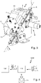
- Fig. 4 shows a highly schematic block diagram of a laboratory automation system 1000 for automatically processing samples 15 contained in laboratory sample containers 2.
- the laboratory sample containers 2 are closed by caps 1 when provided to the laboratory automation system 1000.
- the laboratory automation system 1000 comprises an apparatus 100 for removing the cap 1 closing the laboratory sample container 2 and a laboratory station 1001 being adapted to automatically process the samples 15 contained in the laboratory sample container 2.
- the cap 1 is removed from the laboratory sample container 2 and is then put into a cap tray 11, wherein the sample container 2 without the cap 1 is transported to the laboratory station 1001 for further processing.
- Fig. 1 shows a perspective view on the apparatus 100 for removing the cap 1 closing the laboratory sample container 2 in a dropping position DP.
- the apparatus 100 comprises a cap gripper 3 being adapted to grip the cap 1 to be removed and being adapted to remove the cap 1 being gripped from the laboratory sample container 2.
- the cap gripper 3 may be adapted to rotate the gripped cap 1 around a vertical axis and may further be adapted to vertically move the gripped cap 1 while the laboratory sample container 2 is fixed in its position by means of a laboratory sample container gripping/handling device 17. As depicted, the laboratory sample container 2 is no longer gripped by the laboratory sample container gripping/handling device 17, i.e. the cap 1 has already been successfully removed from the laboratory sample container 2.
- the apparatus 100 further comprises a displaceable chute 4 comprising a cap inlet 5 and a linear guide 6 defining a linear trajectory 7, see fig. 3 , wherein the displaceable chute 4 is mechanically coupled to the linear guide 6 such that the displaceable chute 4 is displaceable only along the linear trajectory 7. In other words, a rotation of the displaceable chute 4 is prevented by the linear guide 6.
- the apparatus 100 further comprises a drive 8 being adapted to cause a displacement of the displaceable chute 4 along the linear trajectory 7 to the dropping position DP, wherein in the dropping position DP the removed cap 1 being gripped by the cap gripper 3 is partially or fully inserted into the cap inlet 5 of the displaceable chute 4, see fig. 1 .
- the linear trajectory 7 forms an angle ⁇ of 40 angular degrees with respect to a horizontal plane.
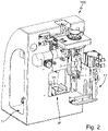
- the drive 8 is adapted to cause a displacement of the displaceable chute 4 along the linear trajectory 7 between the dropping position DP and an idle position IP, see fig. 2 , wherein in the idle position IP the displaceable chute 4 does not restrict any movement of the cap gripper 3.
- the cap inlet 5 is formed by an opening in an upper plate 16 of the displaceable chute 4.
- the upper plate 16 extends horizontally in an operating orientation of the displaceable chute 4.
- the displaceable chute 4 comprises a closed pipe 9, wherein the upper plate 16 is arranged at an upper end of the pipe 9.
- the apparatus 100 comprises a cap tray 11, wherein the displaceable chute 4 comprises a cap outlet 10, the pipe 9 guiding a removed cap 1 being released by the cap gripper 3 from the cap inlet 5 along the pipe 9 towards the cap outlet 10 and into the cap tray 11.
- the drive 8 comprises a tooth bar 12 mounted in/at the linear guide 6, wherein the displaceable chute 4 is mechanically fixed to the tooth bar 12.
- the drive 8 comprises an electric motor 13 and a gear wheel 14 engaging the tooth bar 12, wherein the gear wheel 14 is driven by the electric motor 13 to cause a linear movement of the displaceable chute 4 along the linear trajectory 7.
- the invention solves problems during the decapping process, in particular related to sticky rubber caps 1 and caps 1 not being correctly guided to the cap tray 11. Further spilling and contamination of the laboratory automation system 1000 can be prevented.
- the cap 1 being at least partially inserted into the cap inlet 5 prevents the loss of the cap 1, as the cap is completely enclosed by the displaceable chute 4. In addition, the risk of splashing is significantly reduced. While opening the cap gripper 3, the caps 1 are stripped off towards the pipe 9 and cannot stick to the gripper fingers of the cap gripper 3.
Landscapes
- Analytical Chemistry (AREA)
- Physics & Mathematics (AREA)
- Health & Medical Sciences (AREA)
- Life Sciences & Earth Sciences (AREA)
- Chemical & Material Sciences (AREA)
- Biochemistry (AREA)
- General Health & Medical Sciences (AREA)
- General Physics & Mathematics (AREA)
- Immunology (AREA)
- Pathology (AREA)
- Mechanical Engineering (AREA)
- Engineering & Computer Science (AREA)
- Automatic Analysis And Handling Materials Therefor (AREA)
Abstract
Description
- It is the object of the invention to provide for an apparatus for removing a cap closing a laboratory sample container and a laboratory automation system comprising the apparatus enabling a reliable operation.
- The apparatus is adapted to remove a cap closing a laboratory sample container. The laboratory sample container typically contains a liquid sample, e.g. a blood sample, etc.
- The apparatus comprises a cap gripper being adapted to grip a cap to be removed and being adapted to remove the cap being gripped from the laboratory sample container. To remove the cap, the cap gripper may apply any suitable force to the gripped cap while the laboratory sample container is fixed. The cap gripper may apply a rotational force and/or a transversal force to the cap for a removal of the cap. The laboratory sample container is typically embodied as a laboratory sample tube having a circular cross section. The cap typically comprises a cap head and a cap body, wherein the cap head has a larger diameter than the cap body. The cap head typically has a diameter larger than the diameter of the laboratory sample container and the cap body has a diameter corresponding to the diameter of the laboratory sample container. Typically, the cap body is inserted into the laboratory sample container and the cap head is gripped by the cap gripper to remove the cap body out of the laboratory sample container. Reference insofar is also made to the relevant prior art.
- The apparatus further comprises a displaceable chute comprising a cap inlet. The cap inlet is adapted to receive a removed cap.
- The apparatus further comprises a linear guide defining a, in particular strictly, linear trajectory, wherein the displaceable chute is mechanically coupled to the linear guide such that the displaceable chute is displaceable or displaced, in particular only, along the linear trajectory.
- The apparatus further comprises a drive being adapted to cause a displacement of the displaceable chute along the linear trajectory to a dropping position. In the dropping position of the displaceable chute the removed cap still being gripped by the cap gripper is at least partially inserted into the cap inlet of the displaceable chute. When the cap is released by the cap gripper, the released cap drops through the cap inlet into the chute and is then guided towards a cap tray.
- According to an embodiment the linear trajectory forms an angle with respect to a horizontal plane in a range between 38 angular degrees and 42 angular degrees. In particular, the angle is exactly 40 angular degrees. This angle was determined by means of a space investigation to ensure that the gripped caps do not collide with the chute.
- According to an embodiment the drive is adapted to cause a displacement of the displaceable chute along the linear trajectory between the dropping position and an idle position, wherein in the idle position the displaceable chute does not restrict a rotational and/or linear movement of the cap gripper.
- According to an embodiment the cap inlet is formed by an opening in an upper flat plate of the displaceable chute, the upper plate extending horizontally in an operating orientation of the displaceable chute.
- According to an embodiment the displaceable chute comprises a, in particular closed, pipe, wherein the upper plate is arranged at an upper end of the pipe.
- According to an embodiment the apparatus comprises a cap tray, wherein the displaceable chute, in particular the pipe, comprises a cap outlet, the displaceable chute or pipe guiding a removed cap being released by the cap gripper from/through the cap inlet along the pipe towards the cap outlet and into the cap tray.
- According to an embodiment, the drive comprises a tooth bar mounted in/at the linear guide, wherein the displaceable chute is mechanically fixed to the tooth bar.
- According to an embodiment the drive comprises an electric motor and a gear wheel engaging the tooth bar, wherein the gear wheel is driven by the electric motor. The electric motor may be mechanically fixed to a frame of the apparatus, such that the tooth bar and consequently the displaceable chute moves along the linear trajectory relative to the frame when the gear wheel rotates.
- The laboratory automation system is adapted to automatically process laboratory samples contained in laboratory sample containers. The samples are typically body fluids, such as blood, urine, etc. The laboratory sample containers are typically closed by caps when provided to the laboratory automation system.
- The laboratory automation system comprises an apparatus as described above, and at least one laboratory station functionally coupled to the apparatus and being adapted to automatically process/analyze the samples.
- According to an embodiment the at least one laboratory station is a pre-analytical station, an analytical station, or a post-analytical station.
- Pre-analytical stations may be adapted to perform any kind of pre-processing of samples, sample containers and/or sample container carriers.
- Analytical stations may be adapted to use a sample or part of the sample and a reagent to generate a measuring signal, the measuring signal indicating if and in which concentration, if any, an analyte is existing.
- Post-analytical stations may be adapted to perform any kind of post-processing of samples, sample containers and/or sample container carriers.
- The pre-analytical, analytical and/or post-analytical stations may comprise at least one of a recapping station, an aliquot station, a centrifugation station, an archiving station, a pipetting station, a sorting station, a tube type identification station, a sample quality determining station, an add-on buffer station, a liquid level detection station, and a sealing/desealing station.
- The invention will be described in detail with respect to the drawing schematically depicting embodiments of the invention. In detail:
- fig. 1
- shows a perspective view on an apparatus for removing a cap closing a laboratory sample container,
- fig. 2
- shows another perspective view on the apparatus for removing the cap closing the laboratory sample container from a different perspective,
- fig. 3
- shows a perspective view on a displaceable chute and a corresponding drive of the apparatus for removing the cap closing the laboratory sample container of
figures 1 and2 , and - fig. 4
- shows a highly schematic block diagram of a laboratory automation system comprising the apparatus for removing the cap closing the laboratory sample container of
figures 1 and2 . -
Fig. 4 shows a highly schematic block diagram of alaboratory automation system 1000 for automatically processingsamples 15 contained inlaboratory sample containers 2. Thelaboratory sample containers 2 are closed bycaps 1 when provided to thelaboratory automation system 1000. - The
laboratory automation system 1000 comprises anapparatus 100 for removing thecap 1 closing thelaboratory sample container 2 and alaboratory station 1001 being adapted to automatically process thesamples 15 contained in thelaboratory sample container 2. Thecap 1 is removed from thelaboratory sample container 2 and is then put into acap tray 11, wherein thesample container 2 without thecap 1 is transported to thelaboratory station 1001 for further processing. -
Fig. 1 shows a perspective view on theapparatus 100 for removing thecap 1 closing thelaboratory sample container 2 in a dropping position DP. - The
apparatus 100 comprises acap gripper 3 being adapted to grip thecap 1 to be removed and being adapted to remove thecap 1 being gripped from thelaboratory sample container 2. Thecap gripper 3 may be adapted to rotate thegripped cap 1 around a vertical axis and may further be adapted to vertically move thegripped cap 1 while thelaboratory sample container 2 is fixed in its position by means of a laboratory sample container gripping/handling device 17. As depicted, thelaboratory sample container 2 is no longer gripped by the laboratory sample container gripping/handling device 17, i.e. thecap 1 has already been successfully removed from thelaboratory sample container 2. - The
apparatus 100 further comprises adisplaceable chute 4 comprising acap inlet 5 and alinear guide 6 defining alinear trajectory 7, seefig. 3 , wherein thedisplaceable chute 4 is mechanically coupled to thelinear guide 6 such that thedisplaceable chute 4 is displaceable only along thelinear trajectory 7. In other words, a rotation of thedisplaceable chute 4 is prevented by thelinear guide 6. - The
apparatus 100 further comprises adrive 8 being adapted to cause a displacement of thedisplaceable chute 4 along thelinear trajectory 7 to the dropping position DP, wherein in the dropping position DP the removedcap 1 being gripped by thecap gripper 3 is partially or fully inserted into thecap inlet 5 of thedisplaceable chute 4, seefig. 1 . - Referring to
fig. 3 , thelinear trajectory 7 forms an angle α of 40 angular degrees with respect to a horizontal plane. - The
drive 8 is adapted to cause a displacement of thedisplaceable chute 4 along thelinear trajectory 7 between the dropping position DP and an idle position IP, seefig. 2 , wherein in the idle position IP thedisplaceable chute 4 does not restrict any movement of thecap gripper 3. - E.g. referring to
fig. 3 , thecap inlet 5 is formed by an opening in anupper plate 16 of thedisplaceable chute 4. Theupper plate 16 extends horizontally in an operating orientation of thedisplaceable chute 4. - The
displaceable chute 4 comprises a closedpipe 9, wherein theupper plate 16 is arranged at an upper end of thepipe 9. - The
apparatus 100 comprises acap tray 11, wherein thedisplaceable chute 4 comprises acap outlet 10, thepipe 9 guiding a removedcap 1 being released by thecap gripper 3 from thecap inlet 5 along thepipe 9 towards thecap outlet 10 and into thecap tray 11. - The
drive 8 comprises atooth bar 12 mounted in/at thelinear guide 6, wherein thedisplaceable chute 4 is mechanically fixed to thetooth bar 12. Thedrive 8 comprises anelectric motor 13 and agear wheel 14 engaging thetooth bar 12, wherein thegear wheel 14 is driven by theelectric motor 13 to cause a linear movement of thedisplaceable chute 4 along thelinear trajectory 7. - The invention solves problems during the decapping process, in particular related to
sticky rubber caps 1 and caps 1 not being correctly guided to thecap tray 11. Further spilling and contamination of thelaboratory automation system 1000 can be prevented. Thecap 1 being at least partially inserted into thecap inlet 5 prevents the loss of thecap 1, as the cap is completely enclosed by thedisplaceable chute 4. In addition, the risk of splashing is significantly reduced. While opening thecap gripper 3, thecaps 1 are stripped off towards thepipe 9 and cannot stick to the gripper fingers of thecap gripper 3.
Claims (10)
- Apparatus (100) for removing a cap (1) closing a laboratory sample container (2), the apparatus (100) comprising:- a cap gripper (3) being adapted to grip a cap (1) to be removed and being adapted to remove the cap (1) being gripped from the laboratory sample container (2),- a displaceable chute (4) comprising a cap inlet (5),- a linear guide (6) defining a linear trajectory (7), wherein the displaceable chute (4) is mechanically coupled to the linear guide (6) such that the displaceable chute (4) is displaceable along the linear trajectory (7), and- a drive (8) being adapted to cause a displacement of the displaceable chute (4) along the linear trajectory (7) to a dropping position (DP), wherein in the dropping position (DP) the removed cap (1) being gripped by the cap gripper (3) is at least partially inserted into the cap inlet (5) of the displaceable chute (4).
- Apparatus (100) according to claim 1, characterized in that- the linear trajectory (7) forms an angle (α) with respect to a horizontal plane in a range between 38 angular degrees and 42 angular degrees.
- Apparatus (100) according to one of the preceding claims, characterized in that- the drive (8) is adapted to cause a displacement of the displaceable chute (4) along the linear trajectory (7) between the dropping position (DP) and an idle position (IP), wherein in the idle position (IP) the displaceable chute (4) does not restrict a movement of the cap gripper (3).
- Apparatus (100) according to one of the preceding claims, characterized in that- the cap inlet (5) is formed by an opening in an upper plate (16) of the displaceable chute (4), the upper plate (16) extending horizontally in an operating orientation of the displaceable chute (4).
- Apparatus (100) according to claim 4, characterized in that- the displaceable chute (4) comprises a pipe (9), wherein the upper plate (16) is arranged at an upper end of the pipe (9).
- Apparatus (100) according to claim 5, characterized in that- the apparatus comprises a cap tray (11),- wherein the displaceable chute (4) comprises a cap outlet (10), the displaceable chute (4) guiding a removed cap (1) being released by the cap gripper (3) from the cap inlet (5) along the pipe (9) towards the cap outlet (10) into the cap tray (11).
- Apparatus (100) according to one of the preceding claims, characterized in that- the drive (8) comprises a tooth bar (12) mounted in the linear guide (6), wherein the displaceable chute (4) is mechanically fixed to the tooth bar (12).
- Apparatus (100) according to claim 7, characterized in that- the drive (8) comprises an electric motor (13) and a gear wheel (14) engaging the tooth bar (12), wherein the gear wheel (14) is driven by the electric motor (13).
- Laboratory automation system (1000) for automatically processing samples (15) contained in laboratory sample containers (2), wherein the laboratory sample containers (2) are closed by caps (1) when provided to the laboratory automation system (1000), wherein the laboratory automation system (1000) comprises:- an apparatus (100) according to one of the preceding claims, and- at least one laboratory station (1001) being adapted to automatically process the samples (15).
- Laboratory automation system (1000) according to claim 9, characterized in that the- the at least one laboratory station (1001) is a pre-analytical station, an analytical station, or a post-analytical station.
Priority Applications (4)
| Application Number | Priority Date | Filing Date | Title |
|---|---|---|---|
| EP21162923.3A EP4060350B1 (en) | 2021-03-16 | 2021-03-16 | Apparatus for removing a cap closing a laboratory sample container and laboratory automation system |
| US17/652,569 US12429492B2 (en) | 2021-03-16 | 2022-02-25 | Apparatus for removing a cap closing a laboratory sample container and laboratory automation system |
| JP2022038770A JP7814203B2 (en) | 2021-03-16 | 2022-03-14 | Apparatus for removing caps closing laboratory sample containers and laboratory automation system |
| CN202210255325.9A CN115078749A (en) | 2021-03-16 | 2022-03-15 | Device for removing a lid for closing a laboratory sample container and laboratory automation system |
Applications Claiming Priority (1)
| Application Number | Priority Date | Filing Date | Title |
|---|---|---|---|
| EP21162923.3A EP4060350B1 (en) | 2021-03-16 | 2021-03-16 | Apparatus for removing a cap closing a laboratory sample container and laboratory automation system |
Publications (2)
| Publication Number | Publication Date |
|---|---|
| EP4060350A1 true EP4060350A1 (en) | 2022-09-21 |
| EP4060350B1 EP4060350B1 (en) | 2025-12-03 |
Family
ID=74946999
Family Applications (1)
| Application Number | Title | Priority Date | Filing Date |
|---|---|---|---|
| EP21162923.3A Active EP4060350B1 (en) | 2021-03-16 | 2021-03-16 | Apparatus for removing a cap closing a laboratory sample container and laboratory automation system |
Country Status (4)
| Country | Link |
|---|---|
| US (1) | US12429492B2 (en) |
| EP (1) | EP4060350B1 (en) |
| JP (1) | JP7814203B2 (en) |
| CN (1) | CN115078749A (en) |
Families Citing this family (1)
| Publication number | Priority date | Publication date | Assignee | Title |
|---|---|---|---|---|
| CN115571840A (en) * | 2022-11-04 | 2023-01-06 | 北京雷奥顶峰生物科技有限责任公司 | A quick cap remover |
Citations (3)
| Publication number | Priority date | Publication date | Assignee | Title |
|---|---|---|---|---|
| JPH11230967A (en) * | 1998-02-12 | 1999-08-27 | Mitsubishi Kagaku Bio Clinical Laboratories Inc | Automatic opening device |
| US20030103839A1 (en) * | 2001-11-30 | 2003-06-05 | Forhealth Technologies, Inc. | Automated drug vial safety cap removal |
| US20100043211A1 (en) * | 2006-12-04 | 2010-02-25 | Inpeco Ip Ltd. | Apparatus for removing caps from tubular containers |
Family Cites Families (6)
| Publication number | Priority date | Publication date | Assignee | Title |
|---|---|---|---|---|
| JP2000146985A (en) | 1998-11-09 | 2000-05-26 | Meiko Engineering:Kk | Automatic opening device |
| EP3225972B1 (en) | 2011-09-09 | 2025-03-19 | Gen-Probe Incorporated | Automated sample handling method |
| CN104609348B (en) | 2015-01-26 | 2017-01-25 | 长春迪瑞医疗科技股份有限公司 | An automatic cap-opening device for sample containers |
| WO2016130962A1 (en) * | 2015-02-13 | 2016-08-18 | Abbott Laboratories | Automated storage modules for diagnostic analyzer liquids and related systems and methods |
| WO2016198092A1 (en) * | 2015-06-08 | 2016-12-15 | Stephan Fox | Apparatus for connecting a tube connector to a fitting and to fasten or unfasten closure caps |
| EP3236267B1 (en) | 2016-04-18 | 2021-09-08 | Roche Diagnostics GmbH | Decapper and apparatus |
-
2021
- 2021-03-16 EP EP21162923.3A patent/EP4060350B1/en active Active
-
2022
- 2022-02-25 US US17/652,569 patent/US12429492B2/en active Active
- 2022-03-14 JP JP2022038770A patent/JP7814203B2/en active Active
- 2022-03-15 CN CN202210255325.9A patent/CN115078749A/en active Pending
Patent Citations (3)
| Publication number | Priority date | Publication date | Assignee | Title |
|---|---|---|---|---|
| JPH11230967A (en) * | 1998-02-12 | 1999-08-27 | Mitsubishi Kagaku Bio Clinical Laboratories Inc | Automatic opening device |
| US20030103839A1 (en) * | 2001-11-30 | 2003-06-05 | Forhealth Technologies, Inc. | Automated drug vial safety cap removal |
| US20100043211A1 (en) * | 2006-12-04 | 2010-02-25 | Inpeco Ip Ltd. | Apparatus for removing caps from tubular containers |
Also Published As
| Publication number | Publication date |
|---|---|
| US20220299538A1 (en) | 2022-09-22 |
| EP4060350B1 (en) | 2025-12-03 |
| US12429492B2 (en) | 2025-09-30 |
| JP2022142761A (en) | 2022-09-30 |
| CN115078749A (en) | 2022-09-20 |
| JP7814203B2 (en) | 2026-02-16 |
Similar Documents
| Publication | Publication Date | Title |
|---|---|---|
| US10151765B2 (en) | System for processing closed sample tubes | |
| EP2538227A1 (en) | Device for decapping and recapping sample tubes | |
| CN109073668B (en) | Cap opener and device | |
| US7662339B2 (en) | Apparatus having improved gantry assembly suitable for use in a laboratory environment | |
| EP4051622B1 (en) | Sample tube decapper | |
| US9931644B2 (en) | System and method for automated sample preparation | |
| EP2633329B1 (en) | Apparatus and method for opening and closing a reaction vessel | |
| JP5417353B2 (en) | Automatic analysis system | |
| JPH11230967A (en) | Automatic opening device | |
| EP3418752A1 (en) | Automated analysis device | |
| CN114214183A (en) | Automatic nucleic acid extraction equipment and nucleic acid extraction method thereof | |
| US6253807B1 (en) | Apparatus and process for liquid sample aliquotting | |
| EP4060350B1 (en) | Apparatus for removing a cap closing a laboratory sample container and laboratory automation system | |
| EP2235545B1 (en) | Apparatus for closing biological material containers | |
| EP3477307A1 (en) | Pipetting device and pipetting device positioning system | |
| CN101568386A (en) | Apparatus for removing caps from tubular containers | |
| EP1659090A1 (en) | Method and apparatus for detecting caps on test tubes | |
| CN223857121U (en) | Dairy heavy metal detection workstation | |
| CN114653418B (en) | Laboratory systems for monitoring reference points in laboratory installations | |
| WO2023001733A1 (en) | Active centering device for centering a sample holder in a sample handling system | |
| KR20260046731A (en) | Automated apparatus for concentrating viruses and method thereuse | |
| JP2025179856A (en) | Sample information reading device and sample processing system equipped with the same | |
| HK1180391B (en) | Device for decapping and recapping sample tubes | |
| HK1180039B (en) | System for processing closed sample tubes | |
| JPH0718265U (en) | Blood collection tube opening device |
Legal Events
| Date | Code | Title | Description |
|---|---|---|---|
| PUAI | Public reference made under article 153(3) epc to a published international application that has entered the european phase |
Free format text: ORIGINAL CODE: 0009012 |
|
| STAA | Information on the status of an ep patent application or granted ep patent |
Free format text: STATUS: THE APPLICATION HAS BEEN PUBLISHED |
|
| AK | Designated contracting states |
Kind code of ref document: A1 Designated state(s): AL AT BE BG CH CY CZ DE DK EE ES FI FR GB GR HR HU IE IS IT LI LT LU LV MC MK MT NL NO PL PT RO RS SE SI SK SM TR |
|
| STAA | Information on the status of an ep patent application or granted ep patent |
Free format text: STATUS: REQUEST FOR EXAMINATION WAS MADE |
|
| 17P | Request for examination filed |
Effective date: 20230320 |
|
| RBV | Designated contracting states (corrected) |
Designated state(s): AL AT BE BG CH CY CZ DE DK EE ES FI FR GB GR HR HU IE IS IT LI LT LU LV MC MK MT NL NO PL PT RO RS SE SI SK SM TR |
|
| STAA | Information on the status of an ep patent application or granted ep patent |
Free format text: STATUS: EXAMINATION IS IN PROGRESS |
|
| 17Q | First examination report despatched |
Effective date: 20240522 |
|
| GRAP | Despatch of communication of intention to grant a patent |
Free format text: ORIGINAL CODE: EPIDOSNIGR1 |
|
| STAA | Information on the status of an ep patent application or granted ep patent |
Free format text: STATUS: GRANT OF PATENT IS INTENDED |
|
| RIC1 | Information provided on ipc code assigned before grant |
Ipc: G01N 35/04 20060101AFI20250722BHEP Ipc: B67B 7/18 20060101ALI20250722BHEP |
|
| INTG | Intention to grant announced |
Effective date: 20250731 |
|
| GRAS | Grant fee paid |
Free format text: ORIGINAL CODE: EPIDOSNIGR3 |
|
| GRAA | (expected) grant |
Free format text: ORIGINAL CODE: 0009210 |
|
| STAA | Information on the status of an ep patent application or granted ep patent |
Free format text: STATUS: THE PATENT HAS BEEN GRANTED |
|
| AK | Designated contracting states |
Kind code of ref document: B1 Designated state(s): AL AT BE BG CH CY CZ DE DK EE ES FI FR GB GR HR HU IE IS IT LI LT LU LV MC MK MT NL NO PL PT RO RS SE SI SK SM TR |
|
| REG | Reference to a national code |
Ref country code: CH Ref legal event code: F10 Free format text: ST27 STATUS EVENT CODE: U-0-0-F10-F00 (AS PROVIDED BY THE NATIONAL OFFICE) Effective date: 20251203 Ref country code: GB Ref legal event code: FG4D |
|
| REG | Reference to a national code |
Ref country code: DE Ref legal event code: R096 Ref document number: 602021043447 Country of ref document: DE |
|
| REG | Reference to a national code |
Ref country code: IE Ref legal event code: FG4D |
|
| REG | Reference to a national code |
Ref country code: NL Ref legal event code: MP Effective date: 20251203 |
|
| PGFP | Annual fee paid to national office [announced via postgrant information from national office to epo] |
Ref country code: GB Payment date: 20260219 Year of fee payment: 6 |
|
| PG25 | Lapsed in a contracting state [announced via postgrant information from national office to epo] |
Ref country code: ES Free format text: LAPSE BECAUSE OF FAILURE TO SUBMIT A TRANSLATION OF THE DESCRIPTION OR TO PAY THE FEE WITHIN THE PRESCRIBED TIME-LIMIT Effective date: 20251203 |
|
| REG | Reference to a national code |
Ref country code: LT Ref legal event code: MG9D |
|
| PG25 | Lapsed in a contracting state [announced via postgrant information from national office to epo] |
Ref country code: NO Free format text: LAPSE BECAUSE OF FAILURE TO SUBMIT A TRANSLATION OF THE DESCRIPTION OR TO PAY THE FEE WITHIN THE PRESCRIBED TIME-LIMIT Effective date: 20260303 |
|
| PGFP | Annual fee paid to national office [announced via postgrant information from national office to epo] |
Ref country code: DE Payment date: 20260219 Year of fee payment: 6 |
|
| PG25 | Lapsed in a contracting state [announced via postgrant information from national office to epo] |
Ref country code: FI Free format text: LAPSE BECAUSE OF FAILURE TO SUBMIT A TRANSLATION OF THE DESCRIPTION OR TO PAY THE FEE WITHIN THE PRESCRIBED TIME-LIMIT Effective date: 20251203 Ref country code: HR Free format text: LAPSE BECAUSE OF FAILURE TO SUBMIT A TRANSLATION OF THE DESCRIPTION OR TO PAY THE FEE WITHIN THE PRESCRIBED TIME-LIMIT Effective date: 20251203 |
|
| PG25 | Lapsed in a contracting state [announced via postgrant information from national office to epo] |
Ref country code: RS Free format text: LAPSE BECAUSE OF FAILURE TO SUBMIT A TRANSLATION OF THE DESCRIPTION OR TO PAY THE FEE WITHIN THE PRESCRIBED TIME-LIMIT Effective date: 20260303 |
|
| PGFP | Annual fee paid to national office [announced via postgrant information from national office to epo] |
Ref country code: FR Payment date: 20260220 Year of fee payment: 6 |
|
| PG25 | Lapsed in a contracting state [announced via postgrant information from national office to epo] |
Ref country code: PL Free format text: LAPSE BECAUSE OF FAILURE TO SUBMIT A TRANSLATION OF THE DESCRIPTION OR TO PAY THE FEE WITHIN THE PRESCRIBED TIME-LIMIT Effective date: 20251203 |
|
| PG25 | Lapsed in a contracting state [announced via postgrant information from national office to epo] |
Ref country code: LV Free format text: LAPSE BECAUSE OF FAILURE TO SUBMIT A TRANSLATION OF THE DESCRIPTION OR TO PAY THE FEE WITHIN THE PRESCRIBED TIME-LIMIT Effective date: 20251203 |
|
| PG25 | Lapsed in a contracting state [announced via postgrant information from national office to epo] |
Ref country code: BG Free format text: LAPSE BECAUSE OF FAILURE TO SUBMIT A TRANSLATION OF THE DESCRIPTION OR TO PAY THE FEE WITHIN THE PRESCRIBED TIME-LIMIT Effective date: 20251203 |
|
| REG | Reference to a national code |
Ref country code: AT Ref legal event code: MK05 Ref document number: 1864146 Country of ref document: AT Kind code of ref document: T Effective date: 20251203 |
|
| PG25 | Lapsed in a contracting state [announced via postgrant information from national office to epo] |
Ref country code: NL Free format text: LAPSE BECAUSE OF FAILURE TO SUBMIT A TRANSLATION OF THE DESCRIPTION OR TO PAY THE FEE WITHIN THE PRESCRIBED TIME-LIMIT Effective date: 20251203 |
|
| REG | Reference to a national code |
Ref country code: CH Ref legal event code: W10 Free format text: ST27 STATUS EVENT CODE: U-0-0-W10-W00 (AS PROVIDED BY THE NATIONAL OFFICE) Effective date: 20260624 |
|
| PG25 | Lapsed in a contracting state [announced via postgrant information from national office to epo] |
Ref country code: LT Free format text: LAPSE BECAUSE OF FAILURE TO SUBMIT A TRANSLATION OF THE DESCRIPTION OR TO PAY THE FEE WITHIN THE PRESCRIBED TIME-LIMIT Effective date: 20251203 |
|
| PG25 | Lapsed in a contracting state [announced via postgrant information from national office to epo] |
Ref country code: SM Free format text: LAPSE BECAUSE OF FAILURE TO SUBMIT A TRANSLATION OF THE DESCRIPTION OR TO PAY THE FEE WITHIN THE PRESCRIBED TIME-LIMIT Effective date: 20251203 |
|
| PG25 | Lapsed in a contracting state [announced via postgrant information from national office to epo] |
Ref country code: IT Free format text: LAPSE BECAUSE OF FAILURE TO SUBMIT A TRANSLATION OF THE DESCRIPTION OR TO PAY THE FEE WITHIN THE PRESCRIBED TIME-LIMIT Effective date: 20251203 |
|
| PG25 | Lapsed in a contracting state [announced via postgrant information from national office to epo] |
Ref country code: AT Free format text: LAPSE BECAUSE OF FAILURE TO SUBMIT A TRANSLATION OF THE DESCRIPTION OR TO PAY THE FEE WITHIN THE PRESCRIBED TIME-LIMIT Effective date: 20251203 |
|
| PG25 | Lapsed in a contracting state [announced via postgrant information from national office to epo] |
Ref country code: EE Free format text: LAPSE BECAUSE OF FAILURE TO SUBMIT A TRANSLATION OF THE DESCRIPTION OR TO PAY THE FEE WITHIN THE PRESCRIBED TIME-LIMIT Effective date: 20251203 |
|
| PG25 | Lapsed in a contracting state [announced via postgrant information from national office to epo] |
Ref country code: IS Free format text: LAPSE BECAUSE OF FAILURE TO SUBMIT A TRANSLATION OF THE DESCRIPTION OR TO PAY THE FEE WITHIN THE PRESCRIBED TIME-LIMIT Effective date: 20260403 Ref country code: PT Free format text: LAPSE BECAUSE OF FAILURE TO SUBMIT A TRANSLATION OF THE DESCRIPTION OR TO PAY THE FEE WITHIN THE PRESCRIBED TIME-LIMIT Effective date: 20260406 |
|
| PG25 | Lapsed in a contracting state [announced via postgrant information from national office to epo] |
Ref country code: CZ Free format text: LAPSE BECAUSE OF FAILURE TO SUBMIT A TRANSLATION OF THE DESCRIPTION OR TO PAY THE FEE WITHIN THE PRESCRIBED TIME-LIMIT Effective date: 20251203 |
|
| RAP4 | Party data changed (patent owner data changed or rights of a patent transferred) |
Owner name: ROCHE DIAGNOSTICS GMBH Owner name: F. HOFFMANN-LA ROCHE AG |
|
| PG25 | Lapsed in a contracting state [announced via postgrant information from national office to epo] |
Ref country code: SK Free format text: LAPSE BECAUSE OF FAILURE TO SUBMIT A TRANSLATION OF THE DESCRIPTION OR TO PAY THE FEE WITHIN THE PRESCRIBED TIME-LIMIT Effective date: 20251203 |
|
| PG25 | Lapsed in a contracting state [announced via postgrant information from national office to epo] |
Ref country code: SE Free format text: LAPSE BECAUSE OF FAILURE TO SUBMIT A TRANSLATION OF THE DESCRIPTION OR TO PAY THE FEE WITHIN THE PRESCRIBED TIME-LIMIT Effective date: 20251203 |