EP4060332A1 - Horizontal electrophoresis apparatus - Google Patents
Horizontal electrophoresis apparatus Download PDFInfo
- Publication number
- EP4060332A1 EP4060332A1 EP20887058.4A EP20887058A EP4060332A1 EP 4060332 A1 EP4060332 A1 EP 4060332A1 EP 20887058 A EP20887058 A EP 20887058A EP 4060332 A1 EP4060332 A1 EP 4060332A1
- Authority
- EP
- European Patent Office
- Prior art keywords
- electrode
- electrophoretic gel
- gel
- electrophoresis apparatus
- horizontal electrophoresis
- Prior art date
- Legal status (The legal status is an assumption and is not a legal conclusion. Google has not performed a legal analysis and makes no representation as to the accuracy of the status listed.)
- Withdrawn
Links
Images





Classifications
-
- G—PHYSICS
- G01—MEASURING; TESTING
- G01N—INVESTIGATING OR ANALYSING MATERIALS BY DETERMINING THEIR CHEMICAL OR PHYSICAL PROPERTIES
- G01N27/00—Investigating or analysing materials by the use of electric, electrochemical, or magnetic means
- G01N27/26—Investigating or analysing materials by the use of electric, electrochemical, or magnetic means by investigating electrochemical variables; by using electrolysis or electrophoresis
- G01N27/416—Systems
- G01N27/447—Systems using electrophoresis
- G01N27/44704—Details; Accessories
- G01N27/44713—Particularly adapted electric power supply
-
- G—PHYSICS
- G01—MEASURING; TESTING
- G01N—INVESTIGATING OR ANALYSING MATERIALS BY DETERMINING THEIR CHEMICAL OR PHYSICAL PROPERTIES
- G01N27/00—Investigating or analysing materials by the use of electric, electrochemical, or magnetic means
- G01N27/26—Investigating or analysing materials by the use of electric, electrochemical, or magnetic means by investigating electrochemical variables; by using electrolysis or electrophoresis
- G01N27/416—Systems
- G01N27/447—Systems using electrophoresis
- G01N27/44756—Apparatus specially adapted therefor
-
- C—CHEMISTRY; METALLURGY
- C12—BIOCHEMISTRY; BEER; SPIRITS; WINE; VINEGAR; MICROBIOLOGY; ENZYMOLOGY; MUTATION OR GENETIC ENGINEERING
- C12Q—MEASURING OR TESTING PROCESSES INVOLVING ENZYMES, NUCLEIC ACIDS OR MICROORGANISMS; COMPOSITIONS OR TEST PAPERS THEREFOR; PROCESSES OF PREPARING SUCH COMPOSITIONS; CONDITION-RESPONSIVE CONTROL IN MICROBIOLOGICAL OR ENZYMOLOGICAL PROCESSES
- C12Q1/00—Measuring or testing processes involving enzymes, nucleic acids or microorganisms; Compositions therefor; Processes of preparing such compositions
- C12Q1/68—Measuring or testing processes involving enzymes, nucleic acids or microorganisms; Compositions therefor; Processes of preparing such compositions involving nucleic acids
-
- G—PHYSICS
- G01—MEASURING; TESTING
- G01N—INVESTIGATING OR ANALYSING MATERIALS BY DETERMINING THEIR CHEMICAL OR PHYSICAL PROPERTIES
- G01N27/00—Investigating or analysing materials by the use of electric, electrochemical, or magnetic means
- G01N27/26—Investigating or analysing materials by the use of electric, electrochemical, or magnetic means by investigating electrochemical variables; by using electrolysis or electrophoresis
- G01N27/416—Systems
- G01N27/447—Systems using electrophoresis
- G01N27/44704—Details; Accessories
- G01N27/44747—Composition of gel or of carrier mixture
-
- C—CHEMISTRY; METALLURGY
- C12—BIOCHEMISTRY; BEER; SPIRITS; WINE; VINEGAR; MICROBIOLOGY; ENZYMOLOGY; MUTATION OR GENETIC ENGINEERING
- C12Q—MEASURING OR TESTING PROCESSES INVOLVING ENZYMES, NUCLEIC ACIDS OR MICROORGANISMS; COMPOSITIONS OR TEST PAPERS THEREFOR; PROCESSES OF PREPARING SUCH COMPOSITIONS; CONDITION-RESPONSIVE CONTROL IN MICROBIOLOGICAL OR ENZYMOLOGICAL PROCESSES
- C12Q2565/00—Nucleic acid analysis characterised by mode or means of detection
- C12Q2565/10—Detection mode being characterised by the assay principle
- C12Q2565/125—Electrophoretic separation
Definitions
- the present invention relates to a horizontal electrophoresis apparatus, and more particularly, to a horizontal electrophoresis apparatus which uses a first electrode and a second electrode in close contact with one side of an electrophoretic gel to prevent an electric current difference between the top and bottom of the electrophoretic gel.
- electrophoresis is generally performed for the analysis of nucleic acid molecules (DNA and RNA) or proteins.
- Polyacrylamide gel electrophoresis is a method that uses a polyacrylamide gel for gel electrophoresis.
- the polyacrylamide gel is a porous material which is much denser than an agar gel and thus can be used to separate samples with small molecular weights and small size differences compared to the use of agar.
- sodium dodecyl sulfate-polyacrylamide gel electrophoresis is a method commonly used to spread proteins in a sample in order to efficiently detect a very small amount of proteins.
- the sodium dodecyl sulfite (SDS) binds to the proteins present in the sample to cause the proteins to lose their secondary, tertiary, and quaternary structures and become linear, and provides the proteins with a high density of negative charges such that the proteins are attracted toward the positive pole of the voltage applied during electrophoresis.
- the polyacrylamide gel is a dense porous material, the proteins having a linear structure and negatively charged by SDS can be classified according to the principle that the migration speed varies due to the size of the proteins as the electrophoresis is performed.
- FIG. 1 shows a horizontal PAGE electrophoresis apparatus used for protein analysis.
- the horizontal PAGE electrophoresis for protein analysis is performed in a state where platinum wire electrodes e1 and e2 are placed on both ends of a gel g.
- the platinum wire electrodes e1 and e2 are disposed on the top side of the gel g, and thus an electric current difference occurs between the top and bottom of the gel g.
- the present invention has been made to solve the above-mentioned conventional problems, and the object of the present invention is to provide a horizontal electrophoresis apparatus which uses a first electrode and a second electrode in close contact with one side of an electrophoretic gel to prevent an electric current difference between the top and bottom of the electrophoretic gel.
- the present invention provides a horizontal electrophoresis apparatus comprising a first electrode and a second electrode disposed on both sides of an electrophoretic gel, the first electrode and the second electrode being in close contact with one side of the electrophoretic gel.
- the first electrode and the second electrode may be in close contact with both lateral sides of the electrophoretic gel to face each other with the electrophoretic gel interposed therebetween.
- the electrophoretic gel may be a polymer gel such as polyacrylamide or agar.
- One of the first electrode and the second electrode may be electrically connected to a positive terminal of an external power supply, and the other may be electrically connected to a negative terminal of the external power supply.
- the cross-sections of the first electrode and the second electrode may surround the upper, lower, and lateral sides of the edge of the electrophoretic gel.
- each of the first electrode and the second electrode may comprise two electrodes; an upper electrode and a lower electrode in contact with the upper and lower sides of the electrophoretic gel.
- the interval between the upper electrodes disposed on the upper side of the electrophoretic gel and the interval between the lower electrodes disposed on the lower side of the electrophoretic gel may be adjusted to control the amount of electric current flowing through the electrophoretic gel.
- a wick may be disposed between each of the first electrode and the second electrode and the electrophoretic gel, and the wick may comprise an electrolyte.
- the horizontal electrophoresis apparatus uses the first electrode and the second electrode in close contact with one side of the electrophoretic gel to allow the electric current to flow uniformly over the entire cross section of the electrophoretic gel, thereby preventing an electric current difference between the top and bottom of the electrophoretic gel and solving the problem that the resolution of the protein bands is reduced.
- the horizontal electrophoresis apparatus supplies sufficient electric current also to the lower side of the electrophoretic gel through the first electrode and the second electrode, which reduces the temperature difference between the top, middle and bottom of the electrophoretic gel, resulting in an improved quality of electrophoresis.
- the horizontal electrophoresis apparatus 1 comprises a first electrode 20a and a second electrode 20b disposed on both sides of an electrophoretic gel 10.
- the electrophoretic gel 10 may be a polymer gel such as polyacrylamide, agar, etc.
- the polyacrylamide gel is a porous material which is much denser than an agar gel and thus can be used to separate samples with small molecular weights and small size differences compared to the use of agar.
- the electrophoretic gel 10 may be a polyacrylamide gel (10% resolving gel), but is not limited thereto.
- first electrode 20a and the second electrode 20b may be in close contact with one side of the electrophoretic gel 10.
- the first electrode 20a and the second electrode 20b may be in close contact with both lateral sides of the electrophoretic gel 10 to face each other with the electrophoretic gel 10 interposed therebetween.
- first electrode 20a and the second electrode 20b may be connected to an electric wire to be supplied with electricity from an external power supply.
- one of the first electrode 20a and the second electrode 20b may be electrically connected to a positive terminal of the external power supply, and the other may be electrically connected to a negative terminal of the external power supply.
- each of the first electrode 20a and the second electrode 20b may be a surface electrode made of a conductive material such as platinum, aluminum, etc.
- the electrophoresis process when a protein sample is injected into wells h of the electrophoretic gel 10 and an electric current is supplied from an external power supply to the first electrode 20a and the second electrode 20b through the electric wire, the electric current flows through the electrophoretic gel 10 in close contact with the first electrode 20a and the second electrode 20b, which causes the protein sample to migrate, thereby causing protein separation and performing the electrophoresis.
- the horizontal electrophoresis apparatus 1 uses the first electrode 20a and the second electrode 20b in close contact with both lateral sides of the electrophoretic gel 10 to prevent an electric current difference between the top and bottom of the electrophoretic gel 10.
- the electric current flows uniformly over the entire cross section of the electrophoretic gel 10 through the first electrode 20a and the second electrode 20b, and thus it is possible to solve the problem that a certain portion of the protein band becomes particularly thick as a result of the electrophoresis, which results in a reduced resolution.
- the position where the first electrode 20a and the second electrode 20b are in close contact with the electrophoretic gel 10 is not limited to both lateral sides as shown in FIG. 2, and the first electrode 20a and the second electrode 20b may be disposed in various positions, such as lateral and lower sides, lateral and upper sides, etc., resulting in an improved quality of electrophoresis.
- first electrode 20a and the second electrode 20b of the present invention are used for two-dimensional polyacrylamide gel electrophoresis (2D PAGE), the electric current flows uniformly, which increases the number of protein spots, which serve as a standard for quality assessment of electrophoretic separation.
- the cross sections of the first electrode 20a and the second electrode 20b may surround the upper, lower, and lateral sides of the edge of the electrophoretic gel 10.
- a wick w may be disposed between each of the first electrode 20a and the second electrode 20b and the electrophoretic gel 10, and the wick w may comprise an electrolyte.
- the wick w may comprise a stack of filter papers and may be immersed in an electrolyte solution to allow the electric current to flow.
- the first and second electrodes 20a and 20b and the gel 10 do not directly contact one another, thereby preventing damage to the gel 10 and providing an electrolyte necessary for electrophoresis.
- a PVC film f may be disposed between the first electrode 20a and the second electrode 20b to support the lower side of the electrophoretic gel (10), whereby the electrophoretic gel (10) can be level between the first electrode 20a and the second electrode 20b.
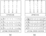
- FIG. 4(a) shows the results of the electrophoresis performed using the first electrode 20a and the second electrode 20b of which the cross sections surround the upper, lower, and lateral sides of the edge of the electrophoretic gel 10 and which have a thickness of 3 mm.
- a pre-stained protein marker was used as a sample, and the sample migrated from top to bottom in the case of the upper side image and from left to right in the case of the lateral cross-sectional image.
- FIG. 4(b) shows the results of the electrophoresis performed at 40 mA using a conventional horizontal electrophoresis apparatus
- the conventional horizontal electrophoresis apparatus has a configuration in which the wire electrodes are disposed only on both top sides of the gel, the electric current strength on the upper side of the gel is higher than that on the lower side, which causes the protein bands to be particularly thick only in a specific region, resulting in a reduced resolution.
- heat generated in the electrophoretic gel 10 during the electrophoresis process may serve to interfere with the electrophoresis.
- sufficient electric current can be also supplied to the lower side of the electrophoretic gel 10 through the first electrode 20a and the second electrode 20b of which the cross sections surround the upper, lower, and lateral sides of the edge of the electrophoretic gel 10.
- the present invention can not only prevent the protein bands from being skewed, but also reduce the temperature difference between the top, middle and bottom of the electrophoretic gel 10, thereby further improving the quality of electrophoresis.
- each of the first electrode 20a and the second electrode 20b may comprise an upper electrode 20a1, 20b1 and a lower electrode 20a2, 20b2, which are in contact with the upper and lower sides of the electrophoretic gel 10, respectively.
- the first electrode 20a disposed on the left side of the electrophoretic gel 10 as shown in FIG. 5 may comprise an upper electrode 20a1 and a lower electrode 20a2
- the second electrode 20b disposed on the right side of the electrophoretic gel 10 as shown in FIG. 5 may comprise an upper electrode 20b1 and a lower electrode 20b2.
- first electrode 20a and the second electrode 20b may be spaced about 1 cm and made of titanium coated with platinum.
- each of the first electrode 20a and the second electrode 20b comprises the upper electrode 20a1, 20b1 and the lower electrode 20a2, 20b2, respectively, which are in contact with the upper and lower sides of the electrophoretic gel 10, the process of bringing the electrodes into contact with the electrophoretic gel 10 becomes easy.
- FIG. 6 shows the amounts of electric current measured using upper electrodes only, using lower electrodes only, and using both the upper and lower electrodes, respectively.
- the thickness of the electrophoretic gel 10 was 3 mm
- the interval between the electrodes was about 6 cm
- the fixed voltage of the power supply was set to 50 V.
- an electrophoresis platform 100 may be used during the electrophoresis, and the electrophoresis platform 100 may comprise electrical terminals 110 and 120, which will be connected to a positive (+) terminal and a negative (-) terminal of a power supply (not shown), respectively, and a pair of rods 130 connected to the electrical terminals 110 and 120.
- the upper electrodes 20a1 and 20b1 and the lower electrodes 20a2 and 20b2 may be connected at their both ends to the rods 130 of the electrophoresis platform 100, respectively, to move their positions, and may be electrically connected to the power supply connected to the electrical terminals 110, 120 through the rods 130.
- grooves h are formed at both ends of the upper electrodes 20a1 and 20b1 and the lower electrodes 20a2 and 20b2. Accordingly, the pair of rods 130 provided in the electrophoresis platform 100 can be inserted into the grooves h, and thus the upper electrode 20a1 and 20b1 and the lower electrodes 20a2 and 20b2 can move their positions along the longitudinal direction of the rods 130.
- the horizontal electrophoresis apparatus 1 of another embodiment of the present invention it is possible to adjust the interval between the upper electrodes 20a1 and 20b1 disposed on the upper side of the electrophoretic gel 10 and the interval between the lower electrodes 20a2 and 20b2 disposed on the lower side of the electrophoretic gel 10.
- FIG. 10 shows the amounts of electric current flowing through the upper electrodes 20a1 and 20b1 disposed on the upper side of the electrophoretic gel 10 at different intervals.
- the fixed voltage of the power supply was set to 50 V.
- the amount of electric current increases as the interval between the upper electrodes 20a1 and 20b1 becomes narrower. That is, it can be seen that the amount of electric current flowing through the electrophoretic gel 10 can easily be controlled by adjusting the interval between the electrodes.
- the intervals between the upper electrodes 20a1 and 20b1 and the lower electrodes 20a2 and 20b2 may be independently adjusted.
- the lower electrodes 20a2 and 20b2 can be moved so that the interval between them becomes narrower
- the upper electrodes 20a1 and 20b1 can be moved so that the interval between them becomes narrower.
- FIGS. 12 to 14 were obtained using a gel 10 having a thickness of 3 mm
- FIG. 15 shows the results of the electrophoresis performed using a commonly used gel 10 having a thickness of 1 mm in a state where the upper electrodes 20a1 and 20b1 and the lower electrodes 20a2 and 20b2 are aligned in the same position.
- the quality of electrophoresis can be improved by adjusting the interval between the upper electrodes 20a1 and 20b1 and the interval between the lower electrodes 20a2 and 20b2 to control the amounts of electric current at the top and bottom.
Landscapes
- Life Sciences & Earth Sciences (AREA)
- Health & Medical Sciences (AREA)
- Chemical & Material Sciences (AREA)
- Molecular Biology (AREA)
- Physics & Mathematics (AREA)
- Analytical Chemistry (AREA)
- Biochemistry (AREA)
- General Health & Medical Sciences (AREA)
- Immunology (AREA)
- Electrochemistry (AREA)
- Chemical Kinetics & Catalysis (AREA)
- General Physics & Mathematics (AREA)
- Pathology (AREA)
- Organic Chemistry (AREA)
- Engineering & Computer Science (AREA)
- Dispersion Chemistry (AREA)
- Zoology (AREA)
- Proteomics, Peptides & Aminoacids (AREA)
- Wood Science & Technology (AREA)
- Biotechnology (AREA)
- Microbiology (AREA)
- Biophysics (AREA)
- Bioinformatics & Cheminformatics (AREA)
- General Engineering & Computer Science (AREA)
- Genetics & Genomics (AREA)
- Power Engineering (AREA)
- Peptides Or Proteins (AREA)
- Investigating Or Analysing Biological Materials (AREA)
Abstract
Description
- The present invention relates to a horizontal electrophoresis apparatus, and more particularly, to a horizontal electrophoresis apparatus which uses a first electrode and a second electrode in close contact with one side of an electrophoretic gel to prevent an electric current difference between the top and bottom of the electrophoretic gel.
- In the field of biotechnology, electrophoresis is generally performed for the analysis of nucleic acid molecules (DNA and RNA) or proteins.
- Polyacrylamide gel electrophoresis (PAGE) is a method that uses a polyacrylamide gel for gel electrophoresis. The polyacrylamide gel is a porous material which is much denser than an agar gel and thus can be used to separate samples with small molecular weights and small size differences compared to the use of agar.
- Meanwhile, sodium dodecyl sulfate-polyacrylamide gel electrophoresis (SDS-PAGE) is a method commonly used to spread proteins in a sample in order to efficiently detect a very small amount of proteins. The sodium dodecyl sulfite (SDS) binds to the proteins present in the sample to cause the proteins to lose their secondary, tertiary, and quaternary structures and become linear, and provides the proteins with a high density of negative charges such that the proteins are attracted toward the positive pole of the voltage applied during electrophoresis.
- At this time, since the polyacrylamide gel is a dense porous material, the proteins having a linear structure and negatively charged by SDS can be classified according to the principle that the migration speed varies due to the size of the proteins as the electrophoresis is performed.
- FIG. 1 shows a horizontal PAGE electrophoresis apparatus used for protein analysis. Referring to FIG. 1, conventionally, the horizontal PAGE electrophoresis for protein analysis is performed in a state where platinum wire electrodes e1 and e2 are placed on both ends of a gel g.
- As such, according to the conventional horizontal PAGE electrophoresis apparatus, the platinum wire electrodes e1 and e2 are disposed on the top side of the gel g, and thus an electric current difference occurs between the top and bottom of the gel g.
- That is, conventionally, more electric current flows through the top side of the gel g on which the platinum wire electrodes e1 and e2 are disposed, and due to this, when the protein sample migrates, the migration speed varies between the top and bottom of the gel g.
- In other words, as the electric current difference occurs as described above, the migration at the top side of the gel g becomes faster, and thus when looking at the development of the protein sample, injected into the wells h, from the side, the protein bands are skewed.
- Due to the above phenomenon, as a result of electrophoresis, the protein bands become thick, which results in a reduced resolution, and in particular, the resolution is significantly reduced for small proteins of medium or smaller size with a long migration distance.
- The present invention has been made to solve the above-mentioned conventional problems, and the object of the present invention is to provide a horizontal electrophoresis apparatus which uses a first electrode and a second electrode in close contact with one side of an electrophoretic gel to prevent an electric current difference between the top and bottom of the electrophoretic gel.
- To achieve the above object, the present invention provides a horizontal electrophoresis apparatus comprising a first electrode and a second electrode disposed on both sides of an electrophoretic gel, the first electrode and the second electrode being in close contact with one side of the electrophoretic gel.
- The first electrode and the second electrode may be in close contact with both lateral sides of the electrophoretic gel to face each other with the electrophoretic gel interposed therebetween.
- The electrophoretic gel may be a polymer gel such as polyacrylamide or agar.
- One of the first electrode and the second electrode may be electrically connected to a positive terminal of an external power supply, and the other may be electrically connected to a negative terminal of the external power supply.
- Moreover, the cross-sections of the first electrode and the second electrode may surround the upper, lower, and lateral sides of the edge of the electrophoretic gel.
- Moreover, each of the first electrode and the second electrode may comprise two electrodes; an upper electrode and a lower electrode in contact with the upper and lower sides of the electrophoretic gel.
- The interval between the upper electrodes disposed on the upper side of the electrophoretic gel and the interval between the lower electrodes disposed on the lower side of the electrophoretic gel may be adjusted to control the amount of electric current flowing through the electrophoretic gel.
- A wick may be disposed between each of the first electrode and the second electrode and the electrophoretic gel, and the wick may comprise an electrolyte.
- The horizontal electrophoresis apparatus according to the present invention uses the first electrode and the second electrode in close contact with one side of the electrophoretic gel to allow the electric current to flow uniformly over the entire cross section of the electrophoretic gel, thereby preventing an electric current difference between the top and bottom of the electrophoretic gel and solving the problem that the resolution of the protein bands is reduced.
- Moreover, the horizontal electrophoresis apparatus according to the present invention supplies sufficient electric current also to the lower side of the electrophoretic gel through the first electrode and the second electrode, which reduces the temperature difference between the top, middle and bottom of the electrophoretic gel, resulting in an improved quality of electrophoresis.
-
- FIG. 1 is a perspective view of a conventional horizontal electrophoresis apparatus.
- FIG. 2 is a perspective view of a horizontal electrophoresis apparatus according to one embodiment of the present invention.
- FIG. 3 is a cross-sectional view of a horizontal electrophoresis apparatus according to another embodiment of the present invention.
- FIG. 4 shows the results of the electrophoresis performed using the electrophoresis apparatus of FIG. 3 and the results of the electrophoresis performed using a conventional horizontal electrophoresis apparatus.
- FIG. 5 is a cross-sectional view of a horizontal electrophoresis apparatus according to another embodiment of the present invention.
- FIG. 6 shows the amounts of electric current measured using upper electrodes only, using lower electrodes only, and using both the upper and lower electrodes, respectively.
- FIG. 7 is a perspective view of an electrophoresis platform on which a horizontal electrophoresis apparatus according to another embodiment of the present invention is installed.
- FIG. 8 is a perspective view showing the upper electrode of FIG. 7.
- FIG. 9 is a perspective view showing the lower electrode of FIG. 7.
- FIG. 10 shows the amounts of electric current flowing through the upper electrodes disposed on the upper side of the electrophoretic gel at different intervals.
- FIG. 11 is a cross-sectional view showing a reduced interval between the lower electrodes of FIG. 5 and a cross-sectional view showing a reduced interval between the upper electrodes of FIG. 5.
- FIG. 12 shows the results of the electrophoresis performed using the electrophoresis apparatus of FIG. 11(a).
- FIG. 13 shows the results of the electrophoresis performed using the electrophoresis apparatus of FIG. 11(b).
- FIG. 14 shows the results of the electrophoresis performed using the electrophoresis apparatus of FIG. 5.
- FIG. 15 shows the results of the electrophoresis performed on an electrophoretic gel having a thickness of 1 mm using the electrophoresis apparatus of FIG. 5.
- Hereinafter, exemplary embodiments of the present invention will be described in detail with reference to the accompanying drawings. First of all, it should be noted that in giving reference numerals to elements of each drawing, like reference numerals refer to like elements even though like elements are shown in different drawings. It should be understood that although the exemplary embodiments of the present invention are described hereafter, the spirit of the present disclosure is not limited thereto and may be practiced by those skilled in the art.
- Hereinafter, a horizontal electrophoresis apparatus according to one embodiment of the present invention will be described with reference to FIG. 2.
- Referring to FIG. 2, the
horizontal electrophoresis apparatus 1 according to one embodiment of the present invention comprises afirst electrode 20a and asecond electrode 20b disposed on both sides of anelectrophoretic gel 10. - Here, the
electrophoretic gel 10 may be a polymer gel such as polyacrylamide, agar, etc. The polyacrylamide gel is a porous material which is much denser than an agar gel and thus can be used to separate samples with small molecular weights and small size differences compared to the use of agar. For example, theelectrophoretic gel 10 may be a polyacrylamide gel (10% resolving gel), but is not limited thereto. - Moreover, the
first electrode 20a and thesecond electrode 20b may be in close contact with one side of theelectrophoretic gel 10. - As shown in FIG. 2, the
first electrode 20a and thesecond electrode 20b may be in close contact with both lateral sides of theelectrophoretic gel 10 to face each other with theelectrophoretic gel 10 interposed therebetween. - Furthermore, the
first electrode 20a and thesecond electrode 20b may be connected to an electric wire to be supplied with electricity from an external power supply. Here, one of thefirst electrode 20a and thesecond electrode 20b may be electrically connected to a positive terminal of the external power supply, and the other may be electrically connected to a negative terminal of the external power supply. - In addition, each of the
first electrode 20a and thesecond electrode 20b may be a surface electrode made of a conductive material such as platinum, aluminum, etc. - For the electrophoresis process, when a protein sample is injected into wells h of the
electrophoretic gel 10 and an electric current is supplied from an external power supply to thefirst electrode 20a and thesecond electrode 20b through the electric wire, the electric current flows through theelectrophoretic gel 10 in close contact with thefirst electrode 20a and thesecond electrode 20b, which causes the protein sample to migrate, thereby causing protein separation and performing the electrophoresis. - As such, unlike the conventional horizontal electrophoresis apparatus as shown in FIG. 1, where the platinum wire electrodes e1 and e2 are placed on both ends of a gel g, the
horizontal electrophoresis apparatus 1 according to the present invention uses thefirst electrode 20a and thesecond electrode 20b in close contact with both lateral sides of theelectrophoretic gel 10 to prevent an electric current difference between the top and bottom of theelectrophoretic gel 10. - That is, the electric current flows uniformly over the entire cross section of the
electrophoretic gel 10 through thefirst electrode 20a and thesecond electrode 20b, and thus it is possible to solve the problem that a certain portion of the protein band becomes particularly thick as a result of the electrophoresis, which results in a reduced resolution. - Meanwhile, according to the
horizontal electrophoresis apparatus 1 of the present invention, the position where thefirst electrode 20a and thesecond electrode 20b are in close contact with theelectrophoretic gel 10 is not limited to both lateral sides as shown in FIG. 2, and thefirst electrode 20a and thesecond electrode 20b may be disposed in various positions, such as lateral and lower sides, lateral and upper sides, etc., resulting in an improved quality of electrophoresis. - In addition, when the
first electrode 20a and thesecond electrode 20b of the present invention are used for two-dimensional polyacrylamide gel electrophoresis (2D PAGE), the electric current flows uniformly, which increases the number of protein spots, which serve as a standard for quality assessment of electrophoretic separation. - Next, the structure of a horizontal electrophoresis apparatus according to another embodiment of the present invention will be described with reference to FIG. 3. For convenience of description, the description of the same elements as those of the embodiment shown in FIG. 2 will be omitted, and the differences will be mainly described below.
- According to the
horizontal electrophoresis apparatus 1 of another embodiment of the present invention, the cross sections of thefirst electrode 20a and thesecond electrode 20b may surround the upper, lower, and lateral sides of the edge of theelectrophoretic gel 10. - Here, a wick w may be disposed between each of the
first electrode 20a and thesecond electrode 20b and theelectrophoretic gel 10, and the wick w may comprise an electrolyte. - Specifically, the wick w may comprise a stack of filter papers and may be immersed in an electrolyte solution to allow the electric current to flow. With the wick w, the first and
second electrodes gel 10 do not directly contact one another, thereby preventing damage to thegel 10 and providing an electrolyte necessary for electrophoresis. - Moreover, a PVC film f may be disposed between the
first electrode 20a and thesecond electrode 20b to support the lower side of the electrophoretic gel (10), whereby the electrophoretic gel (10) can be level between thefirst electrode 20a and thesecond electrode 20b. - FIG. 4(a) shows the results of the electrophoresis performed using the
first electrode 20a and thesecond electrode 20b of which the cross sections surround the upper, lower, and lateral sides of the edge of theelectrophoretic gel 10 and which have a thickness of 3 mm. - At this time, a pre-stained protein marker was used as a sample, and the sample migrated from top to bottom in the case of the upper side image and from left to right in the case of the lateral cross-sectional image.
- As shown in Fig. 4(a), according to the present invention, since the electric current flows uniformly over the entire cross section of the
electrophoretic gel 10 through thefirst electrode 20a and thesecond electrode 20b, it can be seen that as the protein marker migrates during the electrophoresis, the respective protein bands are aligned nearly vertically and clearly distinguished from each other. - FIG. 4(b) shows the results of the electrophoresis performed at 40 mA using a conventional horizontal electrophoresis apparatus
- As shown in Fig. 4(b), in the case of the conventional horizontal electrophoresis apparatus, the bands were shown to lie down while the protein migrated.
- That is, since the conventional horizontal electrophoresis apparatus has a configuration in which the wire electrodes are disposed only on both top sides of the gel, the electric current strength on the upper side of the gel is higher than that on the lower side, which causes the protein bands to be particularly thick only in a specific region, resulting in a reduced resolution.
- Meanwhile, heat generated in the
electrophoretic gel 10 during the electrophoresis process may serve to interfere with the electrophoresis. - However, according to the
horizontal electrophoresis apparatus 1 of the present invention, sufficient electric current can be also supplied to the lower side of theelectrophoretic gel 10 through thefirst electrode 20a and thesecond electrode 20b of which the cross sections surround the upper, lower, and lateral sides of the edge of theelectrophoretic gel 10. - Therefore, the present invention can not only prevent the protein bands from being skewed, but also reduce the temperature difference between the top, middle and bottom of the
electrophoretic gel 10, thereby further improving the quality of electrophoresis. - Next, the structure of a horizontal electrophoresis apparatus according to another embodiment of the present invention will be described with reference to FIG. 5. For convenience of description, the description of the same elements as those of the embodiment shown in FIG. 3 will be omitted, and the differences will be mainly described below.
- According to the
horizontal electrophoresis apparatus 1 of another embodiment of the present invention, each of thefirst electrode 20a and thesecond electrode 20b may comprise an upper electrode 20a1, 20b1 and a lower electrode 20a2, 20b2, which are in contact with the upper and lower sides of theelectrophoretic gel 10, respectively. - Specifically, the
first electrode 20a disposed on the left side of theelectrophoretic gel 10 as shown in FIG. 5 may comprise an upper electrode 20a1 and a lower electrode 20a2, and thesecond electrode 20b disposed on the right side of theelectrophoretic gel 10 as shown in FIG. 5 may comprise an upper electrode 20b1 and a lower electrode 20b2. - Here, the
first electrode 20a and thesecond electrode 20b may be spaced about 1 cm and made of titanium coated with platinum. - As such, since each of the
first electrode 20a and thesecond electrode 20b comprises the upper electrode 20a1, 20b1 and the lower electrode 20a2, 20b2, respectively, which are in contact with the upper and lower sides of theelectrophoretic gel 10, the process of bringing the electrodes into contact with theelectrophoretic gel 10 becomes easy. - FIG. 6 shows the amounts of electric current measured using upper electrodes only, using lower electrodes only, and using both the upper and lower electrodes, respectively. At this time, the thickness of the
electrophoretic gel 10 was 3 mm, the interval between the electrodes was about 6 cm, and the fixed voltage of the power supply was set to 50 V. - As a result of the measurement, it can be seen that, in the case where both the upper electrodes 20a1 and 20b1 and the lower electrodes 20a2 and 20b2 were used as shown in FIG. 6(c), the amount of applied electric current is higher, about two times, than that as shown in FIG. 6(a) and FIG. 6(b), respectively, and the amounts of applied electric current between the upper and lower electrodes are also similar.
- Moreover, it is possible to precisely control the position or thickness of the protein bands by allowing different amounts of electric current to flow through the upper electrodes 20a1 and 20b1 and the lower electrodes 20a2 and 20b2 during the electrophoresis.
- Specifically, referring to FIG. 7, an
electrophoresis platform 100 may be used during the electrophoresis, and theelectrophoresis platform 100 may compriseelectrical terminals rods 130 connected to theelectrical terminals - Here, the upper electrodes 20a1 and 20b1 and the lower electrodes 20a2 and 20b2 may be connected at their both ends to the
rods 130 of theelectrophoresis platform 100, respectively, to move their positions, and may be electrically connected to the power supply connected to theelectrical terminals rods 130. - Referring to FIGS. 8 and 9, grooves h are formed at both ends of the upper electrodes 20a1 and 20b1 and the lower electrodes 20a2 and 20b2. Accordingly, the pair of
rods 130 provided in theelectrophoresis platform 100 can be inserted into the grooves h, and thus the upper electrode 20a1 and 20b1 and the lower electrodes 20a2 and 20b2 can move their positions along the longitudinal direction of therods 130. - As such, according to the
horizontal electrophoresis apparatus 1 of another embodiment of the present invention, it is possible to adjust the interval between the upper electrodes 20a1 and 20b1 disposed on the upper side of theelectrophoretic gel 10 and the interval between the lower electrodes 20a2 and 20b2 disposed on the lower side of theelectrophoretic gel 10. - FIG. 10 shows the amounts of electric current flowing through the upper electrodes 20a1 and 20b1 disposed on the upper side of the
electrophoretic gel 10 at different intervals. At this time, the fixed voltage of the power supply was set to 50 V. - As shown in FIG. 10, it can be seen that the amount of electric current increases as the interval between the upper electrodes 20a1 and 20b1 becomes narrower. That is, it can be seen that the amount of electric current flowing through the
electrophoretic gel 10 can easily be controlled by adjusting the interval between the electrodes. - Referring to FIG. 11, the intervals between the upper electrodes 20a1 and 20b1 and the lower electrodes 20a2 and 20b2 may be independently adjusted.
- That is, as shown in FIG. 11(a), the lower electrodes 20a2 and 20b2 can be moved so that the interval between them becomes narrower, and as shown in FIG. 11(b), the upper electrodes 20a1 and 20b1 can be moved so that the interval between them becomes narrower.
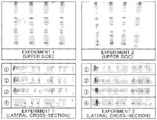
- Referring to FIG. 12, when the interval between the lower electrodes 20a2 and 20b2 is narrowed as in FIG. 11(a), the distance between the lower electrodes 20a2 and 20b2 is relatively close, and thus the amount of electric current flowing along the lower side of the
electrophoretic gel 10 increases, thereby allowing the proteins at the bottom of thegel 10 to migrate faster. As a result, it can be seen that the thickness of the bands observed at the top of thegel 10 becomes wider. - Referring to FIG. 13, when the interval between the upper electrodes 20a1 and 20b1 is narrowed as shown in FIG. 11(b), the distance between the upper electrodes 20a1 and 20b1 is relatively close, and thus the amount of electric current flowing along the upper side of the
electrophoretic gel 10 increases, thereby allowing the proteins at the top of thegel 10 to migrate faster. As a result, it can be seen that the thickness of the bands observed at the bottom of thegel 10 becomes wider. - Referring to FIG. 14, when the interval between the upper electrodes 20a1 and 20b1 and the interval between the lower electrodes 20a2 and 20b2 are set to be the same, it can be seen that the protein bands are aligned nearly vertically.
- The above-mentioned results shown in FIGS. 12 to 14 were obtained using a
gel 10 having a thickness of 3 mm, while FIG. 15 shows the results of the electrophoresis performed using a commonly usedgel 10 having a thickness of 1 mm in a state where the upper electrodes 20a1 and 20b1 and the lower electrodes 20a2 and 20b2 are aligned in the same position. - Unlike the electrophoresis performed using the 3 mm
thick gel 10, in the case where the 1 mmthick gel 10 was used, even if the upper electrodes 20a1 and 20b1 and the lower electrodes 20a2 and 20b2 are aligned in the same position, the protein bands were shown to be skewed in the direction of migration. - To solve this problem, the interval between the lower electrodes 20a2 and 20b2 was further narrowed by 1 cm to increase the amount of electric current flowing to the bottom of the
gel 10, and as a result, the problem that the protein bands were skewed has been improved as shown in FIG. 15(b) - That is, it can be seen that the quality of electrophoresis can be improved by adjusting the interval between the upper electrodes 20a1 and 20b1 and the interval between the lower electrodes 20a2 and 20b2 to control the amounts of electric current at the top and bottom.
- The invention has been described in detail with reference to preferred embodiments thereof. However, it will be appreciated by those skilled in the art that changes may be made in these embodiments without departing from the principles and spirit of the invention, the scope of which is defined in the appended claims and their equivalents.
Claims (8)
- A horizontal electrophoresis apparatus comprising:
a first electrode and a second electrode disposed on both lateral sides of an electrophoretic gel, the first electrode and the second electrode being in close contact with one side of the electrophoretic gel. - The horizontal electrophoresis apparatus of claim 1, wherein the first electrode and the second electrode are in close contact with both lateral sides of the electrophoretic gel to face each other with the electrophoretic gel interposed therebetween.
- The horizontal electrophoresis apparatus of claim 1,
wherein the electrophoretic gel is a polymer gel such as polyacrylamide or agar. - The horizontal electrophoresis apparatus of claim 1,
wherein one of the first electrode and the second electrode is electrically connected to a positive terminal of an external power supply, and the other is electrically connected to a negative terminal of the external power supply. - The horizontal electrophoresis apparatus of claim 1,
wherein the cross-sections of the first electrode and the second electrode surround the upper, lower, and lateral sides of the edge of the electrophoretic gel. - The horizontal electrophoresis apparatus of claim 1,
wherein each of the first electrode and the second electrode comprises an upper electrode and a lower electrode in contact with the upper and lower sides of the electrophoretic gel. - The horizontal electrophoresis apparatus of claim 6,
wherein the interval between the upper electrodes disposed on the upper side of the electrophoretic gel and the interval between the lower electrodes disposed on the lower side of the electrophoretic gel can be adjusted to control the amount of electric current flowing through the electrophoretic gel. - The horizontal electrophoresis apparatus of claim 1,
wherein a wick is disposed between each of the first electrode and the second electrode and the electrophoretic gel, and the wick comprises an electrolyte.
Applications Claiming Priority (2)
| Application Number | Priority Date | Filing Date | Title |
|---|---|---|---|
| KR20190144489 | 2019-11-12 | ||
| PCT/KR2020/014508 WO2021096092A1 (en) | 2019-11-12 | 2020-10-22 | Horizontal electrophoresis apparatus |
Publications (2)
| Publication Number | Publication Date |
|---|---|
| EP4060332A1 true EP4060332A1 (en) | 2022-09-21 |
| EP4060332A4 EP4060332A4 (en) | 2023-12-06 |
Family
ID=75913037
Family Applications (1)
| Application Number | Title | Priority Date | Filing Date |
|---|---|---|---|
| EP20887058.4A Withdrawn EP4060332A4 (en) | 2019-11-12 | 2020-10-22 | HORIZONTAL ELECTROPHORESIS APPARATUS |
Country Status (4)
| Country | Link |
|---|---|
| US (1) | US20220397550A1 (en) |
| EP (1) | EP4060332A4 (en) |
| KR (1) | KR102250148B1 (en) |
| WO (1) | WO2021096092A1 (en) |
Families Citing this family (3)
| Publication number | Priority date | Publication date | Assignee | Title |
|---|---|---|---|---|
| KR102429563B1 (en) | 2021-12-03 | 2022-08-04 | 주식회사 티맥 | Acrylamide gel support for horizontal electrophoresis |
| KR102397413B1 (en) * | 2022-02-24 | 2022-05-12 | 주식회사 미소진 | The gel for electrophoresis marked with the well identification mark |
| KR20250060378A (en) | 2023-10-26 | 2025-05-07 | 주식회사 인텔리전트진 | Integrated gel imaging system for bio analysis |
Family Cites Families (21)
| Publication number | Priority date | Publication date | Assignee | Title |
|---|---|---|---|---|
| US3062731A (en) * | 1959-11-18 | 1962-11-06 | Beckman Instruments Inc | Agar-agar system and additive |
| US3114692A (en) * | 1961-04-27 | 1963-12-17 | Corning Glass Works | Separation process |
| SE386741B (en) * | 1973-01-24 | 1976-08-16 | Lkb Produkter Ab | PROCEDURE FOR ELECTROPHORES, SPEC. IN ISOELECTRIC FOCUSING, CONTROL THE SUPPLIED POWER |
| US5084157A (en) * | 1988-03-21 | 1992-01-28 | California Institute Of Technology | Gel electrophoresis using time dependent contour controlled electric fields |
| GB8825625D0 (en) * | 1988-11-02 | 1988-12-07 | Medical Res Council | Electrophoresis method & apparatus |
| JPH0329844A (en) * | 1989-06-28 | 1991-02-07 | Shimadzu Corp | electrophoresis device |
| JPH0734365U (en) * | 1993-11-30 | 1995-06-23 | 株式会社島津製作所 | Horizontal gel electrophoresis device |
| US5582702A (en) * | 1995-04-26 | 1996-12-10 | Ethrog Biotechnology Ltd. | Apparatus and method for electrophoresis |
| JP2001507441A (en) * | 1995-06-08 | 2001-06-05 | ビジブル ジェネティクス インコーポレイテッド | Microelectrophoresis chip for moving and separating nucleic acids and other charged molecules |
| JPH10288597A (en) * | 1997-04-14 | 1998-10-27 | Toyobo Co Ltd | Electrophoresis device |
| EP0872731B1 (en) * | 1997-04-11 | 2007-06-13 | Toyo Boseki Kabushiki Kaisha | Apparatus for electrophoresis |
| AU8062998A (en) * | 1997-06-09 | 1998-12-30 | Hoeffer Pharmacia Biotech, Inc. | Device and method for applying power to gel electrophoresis modules |
| KR20050040093A (en) * | 2003-11-20 | 2005-05-03 | 주식회사 메덱스바이오 | Electrophoresis system |
| JP2005164477A (en) * | 2003-12-04 | 2005-06-23 | Canon Inc | Electrophoresis container |
| EP2062036A4 (en) * | 2006-08-31 | 2016-09-21 | Life Technologies Israel Ltd | Methods, cassettes, gels and apparatuses for isolation and collection of biomolecules from electrophoresis gels |
| JP4362659B2 (en) * | 2007-05-31 | 2009-11-11 | シャープ株式会社 | Electrophoresis apparatus and electrophoresis method |
| JP2011133311A (en) * | 2009-12-24 | 2011-07-07 | Sharp Corp | Electrophoresis instrument and electrophoresis device |
| GB201102385D0 (en) * | 2011-02-10 | 2011-03-30 | Biocule Scotland Ltd | Two-dimensional gel electrophoresis apparatus and method |
| WO2015156286A1 (en) * | 2014-04-08 | 2015-10-15 | シャープ株式会社 | Isoelectric focusing apparatus and isoelectric focusing method |
| KR101862198B1 (en) | 2016-09-30 | 2018-05-30 | (주)스파크바이오파마 | A method for target protein identification using thermal stability shift-based fluorescence difference in two-dimensional gel electrophoresis |
| KR101900368B1 (en) * | 2017-08-29 | 2018-09-20 | 국립암센터 | Precast gel, electric current providing module, divice for electrophoresis and western blotting and control method thereof |
-
2020
- 2020-10-22 US US17/776,158 patent/US20220397550A1/en not_active Abandoned
- 2020-10-22 EP EP20887058.4A patent/EP4060332A4/en not_active Withdrawn
- 2020-10-22 KR KR1020200137376A patent/KR102250148B1/en active Active
- 2020-10-22 WO PCT/KR2020/014508 patent/WO2021096092A1/en not_active Ceased
Also Published As
| Publication number | Publication date |
|---|---|
| EP4060332A4 (en) | 2023-12-06 |
| KR102250148B1 (en) | 2021-05-10 |
| WO2021096092A1 (en) | 2021-05-20 |
| US20220397550A1 (en) | 2022-12-15 |
Similar Documents
| Publication | Publication Date | Title |
|---|---|---|
| US20220397550A1 (en) | Horizontal electrophoresis apparatus | |
| US4139440A (en) | Electrofocusing in buffers | |
| Keir et al. | Isoelectric focusing of cerebrospinal fluid immunoglobulin G: an annotated update | |
| US20010023825A1 (en) | Methods and apparatus for nonlinear mobility electrophoresis separation | |
| US9945809B2 (en) | Dry protein transfer | |
| EP1907833B1 (en) | Separation of analytes by molecular mass and charge | |
| US4670119A (en) | Isoelectric focusing device and process | |
| Burdett et al. | The separation of the phenotypes of phosphoglucomutase, erythrocyte acid phosphatase, and some haemoglobin variants by isoelectric focusing | |
| Nguyen et al. | Natural pH gradients in buffer mixtures: Formation in the absence of strongly acidic and basic anolyte and catholyte, gradient steepening by sucrose, and stabilization by high buffer concentrations in the electrolyte chambers | |
| EP1538440B1 (en) | Traveling wave grids and algorithms for biomolecule separation, transport and focusing | |
| US5384025A (en) | Notched spacer for slab-gel electrophoresis | |
| EP1211510A1 (en) | Methods and apparatus for nonlinear mobility electrophoresis separation | |
| Abelev et al. | Counterflow immunoisotachophoresis on cellulose acetate membranes | |
| Chartogne et al. | Capillary electrophoretic separations of proteins using carrier ampholytes | |
| US5518604A (en) | Buffer shaping device | |
| US5458760A (en) | Gel composition in gels for submurged gel electrophoresis | |
| Reichel | Application of high‐throughput IEF‐PAGE for EPO‐doping testing | |
| Altland et al. | Flattening, shifting and comparing pH gradients in slab gel electrofocusing by local increases of gel volume | |
| US20170122902A1 (en) | Separation medium cassette for sample separation adsorption and analysis device for sample separation adsorption | |
| JP7057728B2 (en) | Electrophoretic method, electrophoresis system, and storage container for electrophoresis | |
| JPS60242358A (en) | Electrophoresis apparatus | |
| Garfin | Electrophoretic methods | |
| Walker | Isoelectric focusing of proteins in ultra-thin polyacrylamide gels | |
| WO2015156286A1 (en) | Isoelectric focusing apparatus and isoelectric focusing method | |
| Bringard et al. | Multiphasic electrophoresis with diversified spacers |
Legal Events
| Date | Code | Title | Description |
|---|---|---|---|
| STAA | Information on the status of an ep patent application or granted ep patent |
Free format text: STATUS: THE INTERNATIONAL PUBLICATION HAS BEEN MADE |
|
| PUAI | Public reference made under article 153(3) epc to a published international application that has entered the european phase |
Free format text: ORIGINAL CODE: 0009012 |
|
| STAA | Information on the status of an ep patent application or granted ep patent |
Free format text: STATUS: REQUEST FOR EXAMINATION WAS MADE |
|
| 17P | Request for examination filed |
Effective date: 20220610 |
|
| AK | Designated contracting states |
Kind code of ref document: A1 Designated state(s): AL AT BE BG CH CY CZ DE DK EE ES FI FR GB GR HR HU IE IS IT LI LT LU LV MC MK MT NL NO PL PT RO RS SE SI SK SM TR |
|
| DAV | Request for validation of the european patent (deleted) | ||
| DAX | Request for extension of the european patent (deleted) | ||
| A4 | Supplementary search report drawn up and despatched |
Effective date: 20231107 |
|
| RIC1 | Information provided on ipc code assigned before grant |
Ipc: C12Q 1/68 20180101ALI20231031BHEP Ipc: G01N 27/447 20060101AFI20231031BHEP |
|
| STAA | Information on the status of an ep patent application or granted ep patent |
Free format text: STATUS: THE APPLICATION IS DEEMED TO BE WITHDRAWN |
|
| 18D | Application deemed to be withdrawn |
Effective date: 20240525 |