EP4060267A1 - Guiding structure for a drawer and appliance including the guiding structure - Google Patents
Guiding structure for a drawer and appliance including the guiding structure Download PDFInfo
- Publication number
- EP4060267A1 EP4060267A1 EP21162704.7A EP21162704A EP4060267A1 EP 4060267 A1 EP4060267 A1 EP 4060267A1 EP 21162704 A EP21162704 A EP 21162704A EP 4060267 A1 EP4060267 A1 EP 4060267A1
- Authority
- EP
- European Patent Office
- Prior art keywords
- guiding
- drawer
- guiding structure
- supporting guide
- appliance
- Prior art date
- Legal status (The legal status is an assumption and is not a legal conclusion. Google has not performed a legal analysis and makes no representation as to the accuracy of the status listed.)
- Granted
Links
Images

Classifications
-
- F—MECHANICAL ENGINEERING; LIGHTING; HEATING; WEAPONS; BLASTING
- F25—REFRIGERATION OR COOLING; COMBINED HEATING AND REFRIGERATION SYSTEMS; HEAT PUMP SYSTEMS; MANUFACTURE OR STORAGE OF ICE; LIQUEFACTION SOLIDIFICATION OF GASES
- F25D—REFRIGERATORS; COLD ROOMS; ICE-BOXES; COOLING OR FREEZING APPARATUS NOT OTHERWISE PROVIDED FOR
- F25D25/00—Charging, supporting, and discharging the articles to be cooled
- F25D25/02—Charging, supporting, and discharging the articles to be cooled by shelves
- F25D25/024—Slidable shelves
- F25D25/025—Drawers
-
- A—HUMAN NECESSITIES
- A47—FURNITURE; DOMESTIC ARTICLES OR APPLIANCES; COFFEE MILLS; SPICE MILLS; SUCTION CLEANERS IN GENERAL
- A47B—TABLES; DESKS; OFFICE FURNITURE; CABINETS; DRAWERS; GENERAL DETAILS OF FURNITURE
- A47B88/00—Drawers for tables, cabinets or like furniture; Guides for drawers
- A47B88/40—Sliding drawers; Slides or guides therefor
- A47B88/402—Profiles or supporting structures for supporting single drawers
-
- A—HUMAN NECESSITIES
- A47—FURNITURE; DOMESTIC ARTICLES OR APPLIANCES; COFFEE MILLS; SPICE MILLS; SUCTION CLEANERS IN GENERAL
- A47B—TABLES; DESKS; OFFICE FURNITURE; CABINETS; DRAWERS; GENERAL DETAILS OF FURNITURE
- A47B2210/00—General construction of drawers, guides and guide devices
- A47B2210/17—Drawers used in connection with household appliances
- A47B2210/175—Refrigerators or freezers
-
- F—MECHANICAL ENGINEERING; LIGHTING; HEATING; WEAPONS; BLASTING
- F25—REFRIGERATION OR COOLING; COMBINED HEATING AND REFRIGERATION SYSTEMS; HEAT PUMP SYSTEMS; MANUFACTURE OR STORAGE OF ICE; LIQUEFACTION SOLIDIFICATION OF GASES
- F25D—REFRIGERATORS; COLD ROOMS; ICE-BOXES; COOLING OR FREEZING APPARATUS NOT OTHERWISE PROVIDED FOR
- F25D23/00—General constructional features
- F25D23/06—Walls
- F25D23/065—Details
- F25D23/067—Supporting elements
-
- F—MECHANICAL ENGINEERING; LIGHTING; HEATING; WEAPONS; BLASTING
- F25—REFRIGERATION OR COOLING; COMBINED HEATING AND REFRIGERATION SYSTEMS; HEAT PUMP SYSTEMS; MANUFACTURE OR STORAGE OF ICE; LIQUEFACTION SOLIDIFICATION OF GASES
- F25D—REFRIGERATORS; COLD ROOMS; ICE-BOXES; COOLING OR FREEZING APPARATUS NOT OTHERWISE PROVIDED FOR
- F25D2500/00—Problems to be solved
- F25D2500/02—Geometry problems
Definitions
- the present disclosure concerns the field of the appliances and accessories thereof.
- the object of the present disclosure is a guiding structure for drawers of an appliance.
- Cooling appliances in particular refrigerator or freezer or combined refrigerator/freezers, are provided with storing compartments that many times house drawers which are configured to hold items therein.
- the drawers may be typically extracted from a refrigerating compartment of the appliance when subject to a pulling action performed by a user.
- the extraction of the drawer is performed by making the drawer move with respect to the compartment in order to progressively protrude outside thereto.
- the extraction causes typically a motion of the drawer with respect to the compartment along a horizontal or a slightly inclined direction.
- the drawers of a refrigerator or freezer or combined refrigerator/freezer may be configured at least in a first closed configuration (allowing the storing of the food items contained in the drawer to be stored and cooled down within the appliance) wherein they are substantially entirely within the compartment and a second open configuration (allowing the food items to be loaded and unloaded from the the drawer) wherein they are at least partially protruding outside the compartment.
- Drawers are installed on guiding elements, typically arranged at the left and at right side of the drawer, which are configured to allow the extraction of the drawer from the refrigerating compartment, wherein the extraction may be a partial extraction (e.g. for withdrawing a food item from the interior of the drawer) or a full extraction (e.g. for allowing the cleaning of the drawer or of the refrigerating compartment).
- the extraction may be a partial extraction (e.g. for withdrawing a food item from the interior of the drawer) or a full extraction (e.g. for allowing the cleaning of the drawer or of the refrigerating compartment).
- wheels or rollers are typically provided at the guiding elements for providing smoothness in the extraction of the drawer. Guiding elements provided with rollers are described e.g. in document US2017/0234607A1 .
- wheels or rollers involve complex guiding elements, in turn causing at least one of the following specific drawbacks: an increase of production costs, an increase of production timings, the risk of wrong installation of the rollers or wheels, a risk that at least one wheel or roller breaks (thus causing a potential blocking of the drawer), the risk of malfunction due to the presence of ice or frost.
- the present invention is in particular intended to overcome possible malfunctions and/or cost increases connected with the provision of rollers.
- the guiding element comprises a supporting guide (2g) configured for laterally supporting the drawer (200) in correspondence of the lateral guiding rail (201) and further configured for directly contacting the lateral guiding rail (201), the supporting guide (2g) comprising a sliding surface (2s) for the lateral guiding rail (201), in particular against which the lateral guiding rail (201) in use is configured to slide.
- the first guiding element (2') and the second guiding element (2") are at least partially superimposed along a direction transversal, optionally substantially orthogonal, with respect to a direction along which the supporting guide (2g) mainly extends.
- the supporting guides (2g) mainly extend along an axial direction, and realize an at least partially axially extending sliding surface for the lateral guiding rail (201).
- the guiding structure is realized in a single piece and/or in a plastic integral structure and/or in plastic material, in particular in an injection molded plastic material.
- the guiding structure is provided with at least a lateral wall (1w) with respect to which the supporting guide (2g) laterally protrude in a direction that is substantially orthogonal.
- the guiding structure (1) is configured to be coupled, in use, with a respective further guiding structure (1) configured to support the drawers (200) at a side opposite with respect to the side at which the guiding structure (1) is configured to be arranged.
- the guide rib (2r) is configured to confine and limit the motion of the lateral guiding rail (201) in a direction substantially orthogonal with respect to a direction along which the supporting guide (2g) mainly extends and to limit a wobbling of the drawer (200).
- the guide rib (2r) is configured to cooperate with a retaining tooth (201t) of the guiding rail (201) to limit said wobbling of the drawer (200).
- the guiding rail (201) of the drawer (200) is configured to at least partially match the shape overall formed by said sliding surface (2s) and guide rib (2r) and optionally is substantially an "L" shaped guiding rail (201), optionally provided with a first sliding surface and a second sliding surface extending substantially orthogonally.
- the supporting guide (2g) ends with a front resting element (2e), vertically protruding from the sliding surface (2s) and configured to allow the complete extraction of the drawer (200) and/or to allow the removal and/or disconnection and/or separation of the lateral guiding rail (201) from the supporting guide (2g) by moving the drawer (200) in a direction substantially orthogonal to the direction along which the supporting guide (2g) mainly extends and/or by rotating at least partially the drawer (200) and/or by virtue of a composite rototranslation motion of the drawer (200) with respect to the guiding structure (1).
- the guiding structure (1) optionally each of said first guiding element (2') and of said second guiding element (2"), comprises a lateral wall (1w) substantially extending orthogonally to the supporting guide (2g), wherein the lateral wall (1w) comprises a first face and a second face, the second face being opposite to the first face, the supporting guide (2g) being arranged on a first face of the supporting guide 2g.
- the guiding structure (1) comprises at least one fastening clip configured to allow the fastening of said guiding structure (1) to the appliance (100).
- the fastening clip is arranged at the second face of said lateral wall (1w).
- the guiding structure comprising a first and a second through hole (1h) arranged in correspondence of said lateral wall (1w), optionally wherein the first through hole (1h) is arranged substantially at a front portion of the guiding structure and wherein the second through hole (1h) is arranged substantially at a back portion of the guiding structure, the back portion being substantially opposite to the front portion.
- the supporting structure (1) is configured and destined to be installed at a lateral wall of a compartment of said appliance (100).
- first guiding element (2') is at least partially vertically misaligned with respect to the second guiding element (2").
- first and the second guiding elements (2', 2") each comprise a front portion and wherein the front portion of the first guiding element (2') is misaligned with respect to the front portion of the second guiding element (2").
- the supporting guide (2g) of the first guiding element (2') is longer than the supporting guide (2g) of the second guiding element (2").
- At least one among the first guiding element (2') or the second guiding element (2") comprises a back stopping wall (2b) configured to limit the motion of the lateral guiding rail (201) with respect to the supporting guide (2g) at least in a configuration wherein the said supporting guide (2g) is maximally longitudinally superimposed on the lateral guiding rail (201).
- the back stopping wall (2b) is provided at a rear portion, optionally at a rear end portion, of the supporting guide (2g), and/or wherein the back stopping wall (2b) extends substantially orthogonally with respect to the sliding surface.
- the supporting guide (2g) is configured to house at least a layer of lubricant helping the sliding of the guiding rail (201) against the sliding surface (2s); the lubricant optionally comprising at least grease and/or oil, in particular a grease and/or oil being food compatible and/or being at least partially mineral grease and/or oil.
- the layer of lubricant lays substantially over the sliding surface (2s).
- an appliance optionally a refrigerator or freezer or combined refrigerator/freezer, comprising a compartment (100a - 100d), optionally a refrigeration and/or freezing compartment, at least delimited laterally by a left and a right side (100a, 100b) upwardly by an upper side (100c) and at the bottom by a bottom side (100d), the appliance comprising a first and a second guiding structure (1) according to one or more of the present aspects.
- the appliance comprises a first and a second drawer (200), each of the first and the second drawer (200) being configured to be arranged in said compartment (100a - 100d) optionally to be removably housed in said compartment (100a - 100d).
- first and second drawer (200) are removably supported, within the compartment (100a - 100d) by said first and second guiding structure (1).
- said drawer (200) comprises at least a first guiding rail (201) configured to be supported by the supporting guide (2g).
- the at least a first guiding rail (201) is a rigid guiding rail.
- the guiding rail (201) laterally protrudes from a respective lateral wall of the drawer (200), optionally wherein the guiding rail (201) orthogonally protrudes from a respective lateral wall of the drawer (200).
- the guiding rail (201) comprises at least a lower sliding surface, configured to contact, in use, the sliding surface of the supporting guide (2g).
- the drawer (200) comprises a bottom wall (200b), optionally wherein the bottom wall is at least partially perforated.
- the drawer (200) comprises a rear wall (200r), optionally wherein the rear wall (200r) is at least partially perforated.
- the first guiding structure (1) is arranged in correspondence of a left side (100b) of the compartment and the second guiding structure (1) is arranged in correspondence of a right side (100a) of the compartment.
- the drawer (200), optionally each of said first and second drawers (200), comprises a second guiding rail (201) configured to be supported by the supporting guide (2g), wherein the first guiding rail (201) is the left guiding rail (201) and the second guiding rail (201) is the right guiding rail (201).
- the at least a first guiding rail (201) comprises a retaining tooth (201t) configured to cooperate with a guide rib (2r) of the supporting guide (2g) to limit the wobbling of the drawer (200) at least in a direction substantially orthogonal to the direction along which the guiding rail (201) and/or the supporting guide (2g) mainly extend.
- the appliance (100) comprises a first and a second drawer (200), the first drawer being configured so that its left, right guiding rails (201) lay against the supporting guides (2g) of the first guiding element (2') respectively of the first and of the second guiding structures (1).
- the second drawer (200) is configured so that its left, right guiding rail (201) lay against the supporting guides (2g) of the second guiding element (2") respectively of the first and of the second guiding structures (1).
- the first and/or the second drawer (200) comprise(s) at least one through hole (202) arranged at a left lateral wall or a right lateral wall, said through hole (202) being configured for realizing an auxiliary handle for lifting the drawer.
- the first and/or the second drawer (200) comprise a first and a second through hole (202), wherein said first and said second through hole (202) are configured for realizing, each one, an auxiliary handle for lifting the drawer, the first through hole (202) being arranged at a left lateral wall of the respective drawer (200), the second through hole (202) being arranged at a right lateral wall of the respective drawer (200).
- the first and/or the second drawer (200) comprise at least a front handle (203).
- the reference number 1 indicates as guiding structure for drawers 200 of an appliance 100.
- the appliance 100 which is referred to in the present description is a refrigerator or freezer or combined refrigerator/freezer, but this type of appliance shall not be considered limiting.
- the guiding structure which is herein described is conceived for being housed within a compartment of an appliance.
- first reference axis identifies the width of the appliance 100, i.e. is parallel to a direction that joins said right side and left side 100a, 100b.
- a second reference axis or Y axis, identifies the height of the appliance 100 and is orthogonal to the first reference axis.
- a third reference axis, or Z axis identifies the depth of the appliance 100, i.e. is parallel to a direction that joins the front and the rear portion of the appliance 100. The third reference axis is orthogonal to the first and to the second reference axis.
- the appliance 100 comprises an external cabinet and an internal liner, the latter being typically thermoformed. Heat insulation means are operative between the cabinet and the liner. For instance, the volume between the cabinet and the liner may be filled in with insulating foam (alternatively, the appliance 100 may be a vacuum insulated appliance).
- the liner of the appliance defines a compartment, in particular a refrigeration and/or freezing compartment, which is delimited laterally by a right side 100a, or right wall (extending along the Y axis and Z axis), and a left side 100b, or left wall (extending along the Y axis and Z axis), and upwardly by an upper side 100c (extending along the X axis and Z axis) and at the bottom by a lower side 100d (extending along the X axis and Z axis).
- the upper side and the lower side 100c, 100d are preferably opposite and lay on two separate but parallel planes; the right side 100a and the left side 100b are opposite and lay on two separate but parallel planes.
- the compartment is configured for housing a plurality of drawers 200, in particular at least a first and a second superimposed drawers. Said superimposition may take place in a direction parallel to the Y axis.
- the compartment is configured to fully house at least a first and a second drawer.
- the size of the compartment is sufficient to house entirely the first drawer 200 and the second drawer 200, preferably with substantially no protrusion of any part thereof outside said compartment, at least in a particular operative configuration.
- the compartment of the appliance 100 is configured to be closed by a door, in particular a door which preferably rotates around a vertical axis, i.e. around an axis parallel to the Y axis.
- a sealing element is typically provided at a portion of the door which in use contacts the front part of the compartment, especially in case the compartment is the compartment of a refrigerator or freezer or combined refrigerator/freezer.
- first and a second configuration can be identified.
- the drawer 200 is substantially entirely contained within the refrigeration and/or freezing compartment.
- the drawer 200 is extracted by said refrigeration and/or freezing compartment, in particular is at least partially extracted by the compartment.
- the second configuration may be a configuration wherein the drawer 200 is still supported by guiding structures arranged in the compartment.
- the extraction of the drawer 200 i.e. the motion taking place between the first and the second configuration is at least principally an axial translation along an axis that identifies the depth of the compartment.
- the appliance 100 is provided, with guiding structures 1, housed in the compartment in such a way that one guiding structure 1 is arranged at the left lateral wall and the second guiding structure 1 is arranged at the right lateral wall of the compartment. More precisely, the appliance 100 is provided with a first guiding structure 1 and a second guiding structure 1 arranged at the two opposite right and left walls of the compartment.
- the guiding structure 1 is configured to support the drawers 200 at least at a left side or at a right side and being configured to be coupled with a respective further (in detail, opposite) guiding structure 1 configured to support the drawers 200 at a side opposite with respect to the side at which the guiding structure 1 is configured to be arranged.
- the guiding structure 1 comprise at least a first guiding element and a second guiding element identified by reference numbers 2', 2", each configured and destined to contact at least a lateral guiding rail 201 of the drawer 200.
- the main direction of extension of the guiding rail 201 is along said Z axis.
- a guiding structure 1 comprising only a first and a second guiding element is disclosed in detail, it is clear that said guiding structure may comprise at least one further (third) guiding element, and this latter guiding element may have the features of the guiding elements herein described.
- the purpose of the guiding elements 2', 2" is to allow the motion of the drawer 200 along the Z axis, in other words to allow the motion of the drawer 200 in at least a partial extraction from the compartment of the appliance or in at least a partial introduction into the compartment of the drawer 200.
- Each of the left, right guiding rails 201 laterally protrudes from a respective left, right wall of the drawer 200.
- at least part of the guiding rail 201 in particular at least a lower sliding surface of the guiding rail, protrudes orthogonally from the respective lateral wall of the drawer. More precisely, the lower sliding surface, which lays on a plane parallel to the X-Z plane (or on a plane slightly inclined with respect to the X-Z plane), is configured to contact, in use, and slide over the sliding surface of the supporting guide 2g.
- the drawers 200 may be provided with a bottom wall 200b and a back wall 200r.
- the bottom wall 200b and/or the back wall 200r of the drawers may be at least partially perforated and in particular may be provided with a substantially uniform perforation that realizes a sort of net-like structure for the respective wall.
- the lower drawer shown in Figure 4
- the upper drawer shown in Figure 5
- the appliance 100 is provided only with the bucket drawer of Figure 4 , its upper closure may be implemented through a glass shelf accommodated in the compartment above the drawer.
- the guiding rails 201 may be arranged in substantial correspondence of a lower portion of the drawer or alternatively in substantial correspondence of a central portion of the drawer of alternatively at a top portion of the drawer.
- figure 4 shows a drawer whose guiding rails 201 are arranged on the top portion of the lateral walls.
- figure 5 shows a drawer whose guiding rails 201 are arranged at the bottom portion of the lateral walls.
- it is beneficial to configure the guiding rails 201 so that they are arranged on the top of the lower drawer 200 and on the bottom of the upper drawer 200.
- such configurations allow the guiding rails 201 of the drawers 200 to be positioned close to each other and then to optimise the vertical dimension of the guiding structure 1.
- a first drawer 200 may have a vertical extension greater that the vertical extension of a second drawer 200.
- figure 4 shows a drawer that has a greater vertical extension with respect to the drawer of figure 5 .
- figure 4 shows a drawer 200 whose two left, right, lateral walls are provided with a respective through hole identified by the reference number 202.
- the through hole 202 may be present only at one of the lateral walls.
- the through hole 202 is conceived and configured to realize an auxiliary handle for allowing a user laterally grab the drawer.
- the drawer of figure 4 is further provided with a front handle 203 which is preferably part of the front wall thereof and which is intended to facilitate the user in the pulling of the drawer 200 for extracting it from the compartment of the appliance 100.
- the height (measured with respect to the bottom side 100d of the compartment) at which the first guiding element 2' of the right guiding structure 1 is arranged is the same height (always measured with respect to the bottom side 100d of the compartment) at which the first guiding element 2' of the left guiding structure 1 is arranged.
- the drawers 200 are arranged on the guiding elements 2', 2" so that to move on planes which are superimposed and parallel.
- the guiding structure may be configured to allow the simultaneous support of at least a first and a second drawer 200 having different heights or vertical extensions.
- the first guiding element 2' and the second guiding element 2" are configured to allow an independent motion, in particular extraction (from the compartment) or introduction (in the compartment), of the associated drawer 200.
- the first guiding element 2' and the second guiding element 2" comprise a supporting guide 2g configured for laterally supporting, in use, the drawer 200 in correspondence of the lateral guiding rail 201.
- the supporting guide 2g realizes a sliding surface 2s for the lateral guiding rail 201, in particular against which the lateral guiding rail 201 slides.
- first and a second portion of the sliding surface 2s may be identified.
- the first portion may be a front portion and the second portion may be a rear portion.
- the second portion has a slight inclination, in particular a backwards inclination, with respect to the first portion.
- the first portion is in use substantially horizontal.
- the backwards inclination may be useful to assist a full retraction of the drawer 200.
- the backwards inclination allows the drawer 200 to be rotated by pulling the handle 203 upwards in order to obtain the full extraction of the drawer 200 from the compartment (by rendering ineffective the constraint constituted by the resting element 2e that will be described below).
- the guiding rail 201 is thus configured to be supported by the supporting guide 2g and in detail the couple of left, right guiding rails 201 may have sufficient strength to withstand the weight of the drawer 200 when fully loaded.
- the guiding rails 201 may be rigid and optionally may be provided with at least one, preferably a plurality of reinforcing ribs to increase the rigidity thereof with respect to the lateral wall 200k of the drawer 200 at which they are attached.
- each drawer 200 is preferably provided with a left lateral guiding rail 201 and a right lateral guiding rail 201.
- the supporting guide 2g lays below, and thus supports, the lateral guiding rails 201 of each drawer 200.
- the supporting guide 2g is substantially planar, and lays on a plane which in use is at least partially substantially horizontal.
- each drawer 200 protrude laterally and outwardly from the drawer. The same takes place for the supporting guide 2g, which protrude laterally from the first guiding element 2' or from the second guiding element 2".
- the first guiding element 2' and the second guiding element 2" are at least partially superimposed along a direction transversal with respect to a direction along which the supporting guide 2g mainly extends.
- the first guiding element 2' and the second guiding element 2" are superimposed along a vertical direction, i.e. along the Y axis.
- said direction is substantially orthogonal to the direction along which the supporting guide mainly extends.
- the supporting guides 2g mainly extend along an axial direction (i.e. the direction parallel to said Z axis), and realize an at least partially axially extending sliding surface for the lateral guiding rail 201 of the drawer 200.
- each of the guiding structures 1 is realized in a single piece and/or in a plastic integral structure and/or in plastic material.
- the manufacturing process of the guiding structures 1 may comprise plastic provided by means of injection molding.
- the material with which the guiding structures 1 are realized may be a material compatible with the human food chain and further compatible with the human food cold conservation environment.
- the guiding structures 1 may withstand relevant weights in particular when the drawers are completely loaded with heavy food.
- the guiding structures 1 may be provided with a plurality of reinforcing ribs, which in a preferred and non-limiting embodiment may be arranged at least partially along orthogonal directions, in particular along a first horizontal direction parallel to the direction along which the supporting guide 2g mainly extends and along a second vertical direction, orthogonal to the first one.
- the body of the guiding structures 1, especially when realized by means of said molding, may comprise a lateral wall 1w with respect to which the supporting guide 2g laterally protrude orthogonally.
- the reinforcing ribs may be visible on an outer side of the guiding structure 1, i.e. the side that in use is substantially in contact with the wall of the cavity of the appliance.
- the least one supporting guide 2g comprises a guide rib 2r, extending transversally to the sliding surface 2s.
- the guide rib 2r extends orthogonally with respect to the sliding surface 2s.
- the purpose of the guide rib 2r is to confine and limit the motion of the lateral guiding rail 201 in a direction substantially orthogonal with respect to a direction along which the supporting guide 2g mainly extends and to limit the wobbling of the drawer 200.
- the enlarged view of figure 2 clearly shows a gap, identified by the reference number 400 and measured along a direction substantially parallel to X axis between an external surface of the guiding rail 201 and the lateral wall 1w of the guiding structure 1.
- the guiding rail 201 may be provided with a retaining tooth 201t extending for at least part of the extension of the guiding rail 201 (in detail, the extension of the guide along the Z axis).
- the retaining tooth 201t extends downwardly from the guiding rail 201 to cooperate with the guide rib 2r for limiting the wobbling of the drawer 200.
- the guiding rail 201 of the drawer 200 may be preferably configured to at least partially match the shape overall formed by the sliding surface 2s and guide rib 2r.
- the guiding rail 201 is substantially "L" shaped and is provided with a first sliding surface (arranged substantially on a plane that matches the spatial orientation of the plane at which the sliding surface of the supporting guide 2g lays) and a second sliding surface extending substantially orthogonally to the first sliding surface (and being arranged substantially on a plane that matches the spatial orientation of the plane at which the guiding rib 2r substantially extends).
- a first sliding surface arranged substantially on a plane that matches the spatial orientation of the plane at which the sliding surface of the supporting guide 2g lays
- a second sliding surface extending substantially orthogonally to the first sliding surface (and being arranged substantially on a plane that matches the spatial orientation of the plane at which the guiding rib 2r substantially extends).
- such second sliding surface may be a surface of the retaining tooth 201t.
- the embodiment shown in the annexed figures is provided with a supporting guide 2g which ends with a front resting element 2e that protrudes vertically, i.e. along a direction parallel to the Y axis, from the sliding surface 2s.
- the front resting element 2e has a contacting surface, against which the guiding rail 201 of the drawer 200 lays, which uninterruptedly extends from a front end portion of the sliding surface 2s and which in turn realizes an auxiliary sliding surface for the guiding rail 201.
- the purpose of the resting element 2e is to provide a means that reduces the risk of inadvertently fully extracting the drawer 200 from the supporting guide 2g. In this case, if not properly held by the user, the drawer 200 may fall without any remaining support.
- the resting element 2e when present, still allows an intentional full extraction of the drawer, if expressly required by the user (e.g. for cleaning the drawer 200), by lifting (that is, by moving the drawer 200 in a direction substantially orthogonal to the direction along which the supporting guide 2g mainly extends) and/or by rotating at least partially the drawer 200.
- the resting element 2e may be configured to allow a full disconnection of the drawer 200, in particular of the guiding rail 201 from the supporting guide 2g, or equivalently to allow a full extraction of the drawer 200 from the compartment, only by means of a composite movement comprising a rototranslation that takes place between the drawer 200 and the guiding structure 1 here described.
- the guiding rail 201 of the drawer 200 which is provided of a front end portion and an opposite rear end portion, may be provided - in substantial correspondence of said rear end portion - of a stopping portion 201s configured to cooperate with the resting element 2e in order to prevent an unwanted full extraction of the drawer 200 from the supporting guide 2g.
- the stopping portion 201s comprises at least a sliding surface which uninterruptedly joins the sliding surface of the guiding rail 201 but, with respect to this latter, lays on a plane which is inclined with respect to the plane on which the guiding rail slides.
- the stopping portion 201s extends downwardly with respect to the guiding rail 201. It may be noted that the inclination of the sliding surface of the stopping portion 201s may match that of the auxiliary sliding surface of the resting element 2e.
- the auxiliary sliding surface of the resting element 2e contacts the sliding surface of the stopping portion 201s; those two surfaces, are substantially in correspondence of two slightly spaced planes, but ideally assume the same inclination.
- a further extraction of the drawer 200 thus implies a lifting of the drawer 200, which is progressive with the sliding of the auxiliary sliding surface of the resting element 2e with the sliding surface of the stopping portion 201s. Conveniently this may be preferably performed by slightly rotating the front part of the drawer 200 upwardly.
- the guiding structure 1 may be fixed to the wall of the compartment by means of screws.
- the lateral wall 1w may be provided with at least a first through hole 1h configured to house at least one fastening element, in particular the aforementioned screw, so that to allow a rigid fixing of the guiding structure of the side of the compartment.
- the guiding structure 1 is provided with a first and a second though holes 1 h, both realized at the lateral wall 1w.
- the aforementioned through holes when in a plurality, allow to have a more rigid and/or more secure, connection with the compartment.
- a first through hole 1h is arranged at a front portion of the guiding structure and a second through hole 1h is arranged at a rear, and opposite, portion of the guiding structure.
- a retaining element e.g. a screw or a bolt or a fastening clip
- each fastening element 1f comprises an elastically deformable or snap fitting element, in particular a plastic elastically deformable or snap fitting element, optionally realized integrally with the lateral wall 1w in a same moulding process.
- the fastening elements 1f protrude from the lateral wall 1w in a direction that is opposite to the direction of protrusion of the supporting guides 2g.
- the fastening element 1f protrude from an outer face of the lateral wall 1w while the supporting guides 2g protrude from an inner face of the lateral wall 1w, the inner face being opposite to the outer face.
- the annexed figures show an embodiment wherein the guiding structure comprises a combined fastening system comprising said through holes 1h and the fastening elements 1f.
- the free ends of bolts passing through the holes 1h and the free ends of the fastening elements 1f protrude from the outer surface of the internal liner of the appliance 100, so that they remain embedded in the insulating foam, which hence contributes to the stability and to the sealing of the fastening of the guiding structure 1 to the internal liner of the appliance 100.
- the first guiding element 2' is at least partially vertically misaligned with respect to the second guiding element 2", and /or the first and the second guiding elements 2', 2" each comprise a front portion wherein the front portion of the second guiding element 2' is misaligned with respect to the front portion of the second guiding element 2".
- one between the first guiding element 2' and the second guiding element 2" is longer than the second guiding element 2". Thanks to this technical feature the guiding structure allows for providing support for drawers which have to be housed in cavities imposing different depths or with back walls not arranged on a same plane throughout their extension.
- the front portion of the upper guiding element may protrude frontally with respect to the front portion of the lower guiding element while the upper guiding element is shorter than the second guiding element.
- the drawers 200 may not contact directly the back wall of the compartment of the appliance 100, to avoid any problems of adhesion of the drawers 200 to the liner due to the formation of ice or frost on the back wall of the liner.
- a guiding structure wherein at least one among the first and the second guiding elements 2', 2", preferably the first and the second guiding elements 2', 2" are provided with a back stopping wall 2b.
- the back stopping wall 2b is configured to limit the motion of the lateral guiding rail 201 with respect to the supporting guide 2g, at least in a configuration wherein the supporting guide 2g is maximally longitudinally superimposed on the lateral guiding rail 201.
- This configuration corresponds, in use, to a configuration wherein the drawer is maximally introduced in the compartment.
- the back stopping wall 2b extends substantially on a plane which is orthogonal to the plane of the sliding surface, and that - once the guiding structure is installed in the compartment, lays preferably parallel to the plane of the rear wall of the compartment.
- the back stopping wall 2b act as a stopper once the drawer 200 is fully pushed to the rear end of the supporting guide 2g, and cooperates to stop the motion of the drawer 200 helped by the second portion of the supporting guide 2g.
- back stopping wall 2b comprises at least one through hole, configured to house at least at least one retaining element, for fixing the guiding structure 1 to the appliance at a substantially back portion thereof.
- This retaining element may be a screw or a bolt or a fastening clip.
- the through holes arranged at the back stopping wall 2b may provide a synergistic effect of proper attachment of the guiding structure 1 to the appliance when considered with the through holes 1h arranged on the lateral wall of the guiding structure 1.
- the retaining elements introduced in the through holes 1h arranged on the lateral wall of the guiding structure 1 and the retaining elements introduced in the through holes of the back stopping wall 2b may be oriented substantially orthogonally and thus may provide a fastening of the guiding structure along a plurality of different directions, thus helping the overall stability of the assembly formed by the two guiding structures 1 and the drawer 200 also in case of full heavy load.
- the guiding structure 1 shown in figure 2 may be provided with a fastening clip arranged at the lateral wall 1w and conceived for the purpose of allowing a proper, firm, fastening of the guiding structure 1 to the walls of the appliance.
- the fastening clip may be fixed or installed on the lateral wall 1w, e.g. through a screw.
- Several materials may be used for the fastening clip; among these, at least a plastic polymer or metal, e.g. Inox steel, may be used.
- the lateral wall 1w is provided with a first face and a second face, this latter being opposite to the first face.
- Figure 2 shows a guiding structure 1 which may be installed on the right wall of the compartment.
- the first face may be the left face
- the second face may be the right face.
- one face e.g. the first one
- the second one may be the outer face.
- the fastening clip 1c and the supporting guides 2g lay on opposite faces of the lateral wall 1w.
- the supporting guides 2g are arranged on the first, inner, face of the lateral wall 1w and the fastening clip 1c is arranged on the second, outer, face of the lateral wall 1w.
- the fastening clip 1c is arranged at the face of the lateral wall 1w that, in use, when the guiding structure 1 is properly installed into the compartment, is juxtaposed and/or flanks, and/or substantially contacts the lateral wall of the compartment of the appliance 100.
- reinforcement bars 1c made preferably of metal are advantageously applied to the outer surface of the liner of the appliance 100 in order to increase the stiffness of the liner at the installation levels of the guiding structures 1 and hence in order to give a contribution in the support of the drawers 200 and of the food items contained in them.
- the longitudinal extension of the reinforcement bars 1c along substantially the whole longitudinal extension of the supporting guides 2g of the guiding structure allows a uniform and distributed downloading of the weight of the drawers 200 and of the food items contained in them.
- Each guiding structure 1 is fastened to the correspondent reinforcement bar 1c through suitable means, being e.g. screwed or seamed or riveted on snap connected, in such a way that the liner of the appliance 100 remains sandwiched between the guiding structure 1 and the reinforcement bar 1c.
- the lubricant may be oil or grease, in particular a high viscosity oil or grease. It may be noted that such oil or grease may be preferably of a non-toxic or at least a low-toxicity and/or food processing environment compatible (i.e. "food compatible") oil or grease.
- the grease or oil herein described may be of a mineral type.
- the guiding structure 1 herein described is easy and cost effective to produce, and contributes to reduce or anyway keep low the cost of the appliance at which it is installed.
- the guiding structure 1 herein described is robust, and thus contributes to lengthen the operative life without malfunctions for the appliance.
- the guiding structure 1 of the present disclosure allows a precise, easy and fast installation on the appliance 100.
- the guiding structure 1 herein described helps to keep the drawers at a proper place in the appliance compartment, both longitudinally and transversally.
- the guiding structure 1 may be integrally formed with the liner of the household cooling appliance 100.
- the liner of the household appliance 100 may be designed so as to include a couple of guiding structures 1 according to the present invention, arranged at the same level respectively on the right side wall 100a and on the left side wall 100b.
- each of the guiding structures 1 integral to the liner may include a single guiding element, or advantageously a couple of guiding elements 2', 2" configured to support a pair of superimposed drawers 200.
Landscapes
- Engineering & Computer Science (AREA)
- Chemical & Material Sciences (AREA)
- Combustion & Propulsion (AREA)
- Physics & Mathematics (AREA)
- Mechanical Engineering (AREA)
- Thermal Sciences (AREA)
- General Engineering & Computer Science (AREA)
- Drawers Of Furniture (AREA)
Abstract
Description
- The present disclosure concerns the field of the appliances and accessories thereof. In detail, the object of the present disclosure is a guiding structure for drawers of an appliance.
- Cooling appliances, in particular refrigerator or freezer or combined refrigerator/freezers, are provided with storing compartments that many times house drawers which are configured to hold items therein.
- The drawers may be typically extracted from a refrigerating compartment of the appliance when subject to a pulling action performed by a user. The extraction of the drawer is performed by making the drawer move with respect to the compartment in order to progressively protrude outside thereto. The extraction causes typically a motion of the drawer with respect to the compartment along a horizontal or a slightly inclined direction.
- The drawers of a refrigerator or freezer or combined refrigerator/freezer may be configured at least in a first closed configuration (allowing the storing of the food items contained in the drawer to be stored and cooled down within the appliance) wherein they are substantially entirely within the compartment and a second open configuration (allowing the food items to be loaded and unloaded from the the drawer) wherein they are at least partially protruding outside the compartment.
- Drawers are installed on guiding elements, typically arranged at the left and at right side of the drawer, which are configured to allow the extraction of the drawer from the refrigerating compartment, wherein the extraction may be a partial extraction (e.g. for withdrawing a food item from the interior of the drawer) or a full extraction (e.g. for allowing the cleaning of the drawer or of the refrigerating compartment)..
- It may be preferable that the extraction of the drawers is smooth. For this purpose, wheels or rollers are typically provided at the guiding elements for providing smoothness in the extraction of the drawer. Guiding elements provided with rollers are described e.g. in document
US2017/0234607A1 . - It has been noticed that wheels or rollers involve complex guiding elements, in turn causing at least one of the following specific drawbacks: an increase of production costs, an increase of production timings, the risk of wrong installation of the rollers or wheels, a risk that at least one wheel or roller breaks (thus causing a potential blocking of the drawer), the risk of malfunction due to the presence of ice or frost.
- Moreover, the motion of drawers of cooling appliances is often made uncomfortable by the wobbling that ensues when the drawers are pulled or pushed by the users.
- It is an object of the present disclosure to provide a guiding structure, and an associated appliance, that allow to solve the aforementioned drawbacks.
- It is an object of the present disclosure to provide a guiding structure which is simple and which can be manufactured with a cost-effective, and/or time-effective, process.
- The present invention is in particular intended to overcome possible malfunctions and/or cost increases connected with the provision of rollers.
- It is a further object of the present disclosure to provide a guiding structure which allows to realize a smooth motion of the drawer.
- It is a further object of the present disclosure to provide a guiding structure that reduces the risk that the drawers inadvertently fall at a substantially full extraction from the guiding structure.
- It is a further object of the present disclosure to provide a guiding structure which allows to reduce the risk of malfunction in case the refrigerator or freezer or combined refrigerator/freezer presents ice or frost.
- It is a further object of the present disclosure to provide a guiding structure which is robust and reliable.
- It is a further aim of the present invention to prevent possible wobbling occurring during the extraction of the drawer from the compartment.
- It is a further object of the present disclosure to provide a guiding structure which allows to support a plurality of drawers.
- It is a further aim of the present invention to achieve optimisations in the number of components of a household cooling appliance comprising a couple of superimposed drawers and in the manufacturing process of such a household cooling appliance.
- It is a further object of the present disclosure to provide a guiding structure which allows an independent motion at least of a first and a second drawer.
- It is a further object of the present disclosure to provide a guiding structure which allows to support drawers having different sizes, in particular different heights.
- It is a further object of the present disclosure to provide a guiding structure whose materials are compatible with human food chain, especially with human food cold conservation.
- The object of the present disclosure will be described hereinafter in accordance to a plurality of aspects which can be combined together in any suitable form and which can be further combined with portions of description and/or of the annexed claims.
- According to the most general aspect of the present disclosure, it is herewith provided a guiding structure (1) for at least one drawer (200) of an appliance (100), in particular a household cooling appliance, the guiding structure (1) being configured to be arranged on a side wall (100a; 100b) of an internal liner of said appliance (100) and comprising at least one a guiding element configured to contact at least a lateral guiding rail (201) of said drawer (200). According to the invention, the guiding element comprises a supporting guide (2g) configured for laterally supporting the drawer (200) in correspondence of the lateral guiding rail (201) and further configured for directly contacting the lateral guiding rail (201), the supporting guide (2g) comprising a sliding surface (2s) for the lateral guiding rail (201), in particular against which the lateral guiding rail (201) in use is configured to slide.
- According to the present disclosure it is moreover provided a guiding structure (1) for drawers (200) of an appliance (100), the guiding structure (1) being configured to be installed on a side (100a; 100b) or at a lateral wall of said appliance (100) and comprising at least a first guiding element (2') and a second guiding element (2") each configured and destined to contact at least a lateral guiding rail (201) of a respective drawer (200);
wherein: - the first guiding element (2') and the second guiding element (2") are configured to allow an independent motion of said respective drawer (200) ;
- each of the first guiding element (2') and of the second guiding element (2") comprise a supporting guide (2g) configured for laterally supporting the drawer (200) in correspondence of the lateral guiding rail (201) and configured for directly contacting the lateral guiding rail (201); the supporting guide (2g) comprising a sliding surface (2s) for the lateral guiding rail (201), in particular against which the lateral guiding rail (201) in use is configured to slide.
- According to a further, non-limiting, aspect, the first guiding element (2') and the second guiding element (2") are at least partially superimposed along a direction transversal, optionally substantially orthogonal, with respect to a direction along which the supporting guide (2g) mainly extends.
- According to a further, non-limiting, aspect, the first guiding element (2') and the second guiding element (2") are configured to allow a relative motion of a first drawer (200) operatively connected to the first guiding element (2') with respect to a second drawer (200) operatively connected to the second guiding element (2").
- According to a further, non-limiting, aspect, the supporting guides (2g) mainly extend along an axial direction, and realize an at least partially axially extending sliding surface for the lateral guiding rail (201).
- According to a further, non-limiting, aspect, the guiding structure is realized in a single piece and/or in a plastic integral structure and/or in plastic material, in particular in an injection molded plastic material.
- According to a further, non-limiting, aspect, the guiding structure is provided with at least a lateral wall (1w) with respect to which the supporting guide (2g) laterally protrude in a direction that is substantially orthogonal.
- According to a further, non-limiting, aspect, the guiding structure (1) is configured to support the drawers (200) at least at a left side or at a right side thereof.
- According to a further, non-limiting, aspect, the guiding structure (1) is configured to be coupled, in use, with a respective further guiding structure (1) configured to support the drawers (200) at a side opposite with respect to the side at which the guiding structure (1) is configured to be arranged.
- According to a further, non-limiting, aspect, at least one supporting guide (2g) comprises a guide rib (2r) extending transversally to said sliding surface (2s), optionally extending substantially orthogonally with respect to said sliding surface (2s).
- According to a further, non-limiting, aspect, the guide rib (2r) is configured to confine and limit the motion of the lateral guiding rail (201) in a direction substantially orthogonal with respect to a direction along which the supporting guide (2g) mainly extends and to limit a wobbling of the drawer (200).
- According to a further, non-limiting aspect, the guide rib (2r) is configured to cooperate with a retaining tooth (201t) of the guiding rail (201) to limit said wobbling of the drawer (200).
- According to a further, non-limiting, aspect, the guiding rail (201) of the drawer (200) is configured to at least partially match the shape overall formed by said sliding surface (2s) and guide rib (2r) and optionally is substantially an "L" shaped guiding rail (201), optionally provided with a first sliding surface and a second sliding surface extending substantially orthogonally.
- According to a further, non-limiting, aspect, the supporting guide (2g) ends with a front resting element (2e), vertically protruding from the sliding surface (2s) and configured to allow the complete extraction of the drawer (200) and/or to allow the removal and/or disconnection and/or separation of the lateral guiding rail (201) from the supporting guide (2g) by moving the drawer (200) in a direction substantially orthogonal to the direction along which the supporting guide (2g) mainly extends and/or by rotating at least partially the drawer (200) and/or by virtue of a composite rototranslation motion of the drawer (200) with respect to the guiding structure (1).
- According to a further, non-limiting, aspect, at least a first through hole (1h) arranged in correspondence of said lateral wall (1w), the through hole (1h) being configured to house at least one fastening element, in particular a screw, configured to allow the rigid fixing of the guiding structure to said side (100a; 100b) of said appliance (100).
- According to a further, non-limiting, aspect, the guiding structure (1), optionally each of said first guiding element (2') and of said second guiding element (2"), comprises a lateral wall (1w) substantially extending orthogonally to the supporting guide (2g), wherein the lateral wall (1w) comprises a first face and a second face, the second face being opposite to the first face, the supporting guide (2g) being arranged on a first face of the supporting
guide 2g. - According to a further, non-limiting, aspect, the guiding structure (1) comprises at least one fastening clip configured to allow the fastening of said guiding structure (1) to the appliance (100).
- According to a further, non-limiting, aspect, the fastening clip is arranged at the second face of said lateral wall (1w).
- According to a further, non-limiting, aspect, the guiding structure comprising a first and a second through hole (1h) arranged in correspondence of said lateral wall (1w), optionally wherein the first through hole (1h) is arranged substantially at a front portion of the guiding structure and wherein the second through hole (1h) is arranged substantially at a back portion of the guiding structure, the back portion being substantially opposite to the front portion.
- According to a further, non-limiting, aspect, the supporting structure (1) is configured and destined to be installed at a lateral wall of a compartment of said appliance (100).
- According to a further, non-limiting, aspect, further comprising at least a fastening element (1f), configured to allow a removable fastening of the structure to an inner wall of the appliance (100), the fastening element (1f) comprising an elastically deformable or snap fitting element, in particular a plastic elastically deformable or snap fitting element.
- According to a further, non-limiting, aspect, wherein the first guiding element (2') is at least partially vertically misaligned with respect to the second guiding element (2").
- According to a further, non-limiting, aspect, the first and the second guiding elements (2', 2") each comprise a front portion and wherein the front portion of the first guiding element (2') is misaligned with respect to the front portion of the second guiding element (2").
- According to a further, non-limiting, aspect, the supporting guide (2g) of the first guiding element (2') is longer than the supporting guide (2g) of the second guiding element (2").
- According to a further, non-limiting, aspect, at least one among the first guiding element (2') or the second guiding element (2") comprises a back stopping wall (2b) configured to limit the motion of the lateral guiding rail (201) with respect to the supporting guide (2g) at least in a configuration wherein the said supporting guide (2g) is maximally longitudinally superimposed on the lateral guiding rail (201).
- According to a further, non-limiting, aspect, the back stopping wall (2b) is provided at a rear portion, optionally at a rear end portion, of the supporting guide (2g), and/or wherein the back stopping wall (2b) extends substantially orthogonally with respect to the sliding surface.
- According to a further, non-limiting, aspect, the supporting guide (2g) is configured to house at least a layer of lubricant helping the sliding of the guiding rail (201) against the sliding surface (2s); the lubricant optionally comprising at least grease and/or oil, in particular a grease and/or oil being food compatible and/or being at least partially mineral grease and/or oil.
- According to a further, non-limiting- aspect, the layer of lubricant lays substantially over the sliding surface (2s).
- According to another aspect, it is disclosed an appliance, optionally a refrigerator or freezer or combined refrigerator/freezer, comprising a compartment (100a - 100d), optionally a refrigeration and/or freezing compartment, at least delimited laterally by a left and a right side (100a, 100b) upwardly by an upper side (100c) and at the bottom by a bottom side (100d), the appliance comprising a first and a second guiding structure (1) according to one or more of the present aspects.
- According to a further, non-limiting, aspect, the appliance comprises a first and a second drawer (200), each of the first and the second drawer (200) being configured to be arranged in said compartment (100a - 100d) optionally to be removably housed in said compartment (100a - 100d).
- According to a further, non-limiting, aspect, the first and second drawer (200) are removably supported, within the compartment (100a - 100d) by said first and second guiding structure (1).
- According to a further, non-limiting, aspect, said drawer (200) comprises at least a first guiding rail (201) configured to be supported by the supporting guide (2g).
- According to a further, non-limiting, aspect, the at least a first guiding rail (201) is a rigid guiding rail.
- According to another non-limiting aspect, the guiding rail (201) laterally protrudes from a respective lateral wall of the drawer (200), optionally wherein the guiding rail (201) orthogonally protrudes from a respective lateral wall of the drawer (200).
- According to a further, non-limiting, aspect, the guiding rail (201) comprises at least a lower sliding surface, configured to contact, in use, the sliding surface of the supporting guide (2g).
- According to a further, non-limiting, aspect, the drawer (200) comprises a bottom wall (200b), optionally wherein the bottom wall is at least partially perforated.
- According to a further, non-limiting, aspect, the drawer (200) comprises a rear wall (200r), optionally wherein the rear wall (200r) is at least partially perforated.
- According to a further, non-limiting, aspect, the first guiding structure (1) is arranged in correspondence of a left side (100b) of the compartment and the second guiding structure (1) is arranged in correspondence of a right side (100a) of the compartment.
- According to a further, non-limiting, aspect, the drawer (200), optionally each of said first and second drawers (200), comprises a second guiding rail (201) configured to be supported by the supporting guide (2g), wherein the first guiding rail (201) is the left guiding rail (201) and the second guiding rail (201) is the right guiding rail (201).
- According to a further, non-limiting, aspect, the at least a first guiding rail (201) comprises a retaining tooth (201t) configured to cooperate with a guide rib (2r) of the supporting guide (2g) to limit the wobbling of the drawer (200) at least in a direction substantially orthogonal to the direction along which the guiding rail (201) and/or the supporting guide (2g) mainly extend.
- According to a further, non-limiting, aspect, the appliance (100) comprises a first and a second drawer (200), the first drawer being configured so that its left, right guiding rails (201) lay against the supporting guides (2g) of the first guiding element (2') respectively of the first and of the second guiding structures (1).
- According to a further, non-limiting, aspect, the second drawer (200) is configured so that its left, right guiding rail (201) lay against the supporting guides (2g) of the second guiding element (2") respectively of the first and of the second guiding structures (1).
- According to a further, non-limiting, aspect, the first and/or the second drawer (200) comprise(s) at least one through hole (202) arranged at a left lateral wall or a right lateral wall, said through hole (202) being configured for realizing an auxiliary handle for lifting the drawer.
- According to a further, non-limiting, aspect, the first and/or the second drawer (200) comprise a first and a second through hole (202), wherein said first and said second through hole (202) are configured for realizing, each one, an auxiliary handle for lifting the drawer, the first through hole (202) being arranged at a left lateral wall of the respective drawer (200), the second through hole (202) being arranged at a right lateral wall of the respective drawer (200).
- According to a further, non-limiting, aspect, the first and/or the second drawer (200) comprise at least a front handle (203).
- The invention will be disclosed in at least one preferred, albeit non-limiting, embodiment, by referring to the annexed figures wherein:
-
figure 1 shows a perspective view of an appliance provided with a first and a second drawer and with a couple (left, right) of guiding structures according to the present disclosure; -
figure 2 shows a section view along the plane X-Y of the appliance offigure 1 ; -
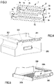
figure 3 shows a perspective view of the guiding structure according to the present disclosure; -
figure 4 shows a perspective view of a first drawer; -
figure 5 shows a perspective view of a second drawer. - As regards the embodiment of the invention shown in
Figures 1 to 5 , it is in particular observed that such embodiments contemplates the provision of a couple of superimposed drawers within the compartment of the household cooling appliance. Consequently, also the guiding structures are configured for supporting a couple of drawers, each guiding structure including a couple of superimposed guiding elements. However, it has to be remarked that the invention is not limited in this respect, since the guiding structure may be alternatively configured for supporting only one drawer within the compartment of the appliance and hence may comprise in particular a single guiding element. - The reference number 1 indicates as guiding structure for
drawers 200 of anappliance 100. Theappliance 100 which is referred to in the present description is a refrigerator or freezer or combined refrigerator/freezer, but this type of appliance shall not be considered limiting. - The guiding structure which is herein described is conceived for being housed within a compartment of an appliance.
- For the purposes of increasing the intelligibility of the present description, directions will be described by referring to the following axis:
- X axis: denotes the width of the compartment of the appliance, and in use may be substantially horizontal;
- Y axis: denotes the height of the compartment of the appliance, and in use may be substantially vertical;
- Z axis: denotes the depth of the compartment of the appliance, and in use may be substantially horizontal.
- In other words first reference axis, or X axis, identifies the width of the
appliance 100, i.e. is parallel to a direction that joins said right side and leftside appliance 100 and is orthogonal to the first reference axis. A third reference axis, or Z axis, identifies the depth of theappliance 100, i.e. is parallel to a direction that joins the front and the rear portion of theappliance 100. The third reference axis is orthogonal to the first and to the second reference axis. - The
appliance 100 comprises an external cabinet and an internal liner, the latter being typically thermoformed. Heat insulation means are operative between the cabinet and the liner. For instance, the volume between the cabinet and the liner may be filled in with insulating foam (alternatively, theappliance 100 may be a vacuum insulated appliance). The liner of the appliance defines a compartment, in particular a refrigeration and/or freezing compartment, which is delimited laterally by aright side 100a, or right wall (extending along the Y axis and Z axis), and aleft side 100b, or left wall (extending along the Y axis and Z axis), and upwardly by anupper side 100c (extending along the X axis and Z axis) and at the bottom by alower side 100d (extending along the X axis and Z axis). - The upper side and the
lower side right side 100a and theleft side 100b are opposite and lay on two separate but parallel planes. - The compartment is configured for housing a plurality of
drawers 200, in particular at least a first and a second superimposed drawers. Said superimposition may take place in a direction parallel to the Y axis. In an embodiment, which is the embodiment of the annexed figures, the compartment is configured to fully house at least a first and a second drawer. In other words, the size of the compartment is sufficient to house entirely thefirst drawer 200 and thesecond drawer 200, preferably with substantially no protrusion of any part thereof outside said compartment, at least in a particular operative configuration. - The compartment of the
appliance 100 is configured to be closed by a door, in particular a door which preferably rotates around a vertical axis, i.e. around an axis parallel to the Y axis. A sealing element is typically provided at a portion of the door which in use contacts the front part of the compartment, especially in case the compartment is the compartment of a refrigerator or freezer or combined refrigerator/freezer. - When considering the position of each of the
drawers 200 with respect to the compartment, at least a first and a second configuration can be identified. In a first configuration, thedrawer 200 is substantially entirely contained within the refrigeration and/or freezing compartment. In a second configuration, thedrawer 200 is extracted by said refrigeration and/or freezing compartment, in particular is at least partially extracted by the compartment. The second configuration may be a configuration wherein thedrawer 200 is still supported by guiding structures arranged in the compartment. - The extraction of the
drawer 200, i.e. the motion taking place between the first and the second configuration is at least principally an axial translation along an axis that identifies the depth of the compartment. - The
appliance 100 is provided, with guiding structures 1, housed in the compartment in such a way that one guiding structure 1 is arranged at the left lateral wall and the second guiding structure 1 is arranged at the right lateral wall of the compartment. More precisely, theappliance 100 is provided with a first guiding structure 1 and a second guiding structure 1 arranged at the two opposite right and left walls of the compartment. Technical details of the guiding structures 1 will be hereinafter disclosed. In other words, the guiding structure 1 is configured to support thedrawers 200 at least at a left side or at a right side and being configured to be coupled with a respective further (in detail, opposite) guiding structure 1 configured to support thedrawers 200 at a side opposite with respect to the side at which the guiding structure 1 is configured to be arranged. - The guiding structure 1 comprise at least a first guiding element and a second guiding element identified by
reference numbers 2', 2", each configured and destined to contact at least alateral guiding rail 201 of thedrawer 200. The main direction of extension of the guidingrail 201 is along said Z axis. - Albeit in the present description a guiding structure 1 comprising only a first and a second guiding element is disclosed in detail, it is clear that said guiding structure may comprise at least one further (third) guiding element, and this latter guiding element may have the features of the guiding elements herein described.
- The purpose of the guiding
elements 2', 2" is to allow the motion of thedrawer 200 along the Z axis, in other words to allow the motion of thedrawer 200 in at least a partial extraction from the compartment of the appliance or in at least a partial introduction into the compartment of thedrawer 200. - Each of the left, right guiding rails 201 laterally protrudes from a respective left, right wall of the
drawer 200. In the embodiment shown in the annexed figures, at least part of the guidingrail 201, in particular at least a lower sliding surface of the guiding rail, protrudes orthogonally from the respective lateral wall of the drawer. More precisely, the lower sliding surface, which lays on a plane parallel to the X-Z plane (or on a plane slightly inclined with respect to the X-Z plane), is configured to contact, in use, and slide over the sliding surface of the supportingguide 2g. - Several types of drawers may be present in the appliance. The
drawers 200 may be provided with abottom wall 200b and aback wall 200r. Alternatively or in combination, thebottom wall 200b and/or theback wall 200r of the drawers may be at least partially perforated and in particular may be provided with a substantially uniform perforation that realizes a sort of net-like structure for the respective wall. According to the explanatory embodiment shown in the Figures, the lower drawer (shown inFigure 4 ) has a bucket configuration, whilst the upper drawer (shown inFigure 5 ) extends in the vertical direction appreciably less than the lower drawer and acts as a sliding cover for the lower drawer. If theappliance 100 is provided only with the bucket drawer ofFigure 4 , its upper closure may be implemented through a glass shelf accommodated in the compartment above the drawer. - In accordance to the specific design of the drawer, the guiding
rails 201 may be arranged in substantial correspondence of a lower portion of the drawer or alternatively in substantial correspondence of a central portion of the drawer of alternatively at a top portion of the drawer. In particular,figure 4 shows a drawer whose guiding rails 201 are arranged on the top portion of the lateral walls. In contrast,figure 5 shows a drawer whose guiding rails 201 are arranged at the bottom portion of the lateral walls. In fact, in case of superimposed drawers, it is beneficial to configure the guidingrails 201 so that they are arranged on the top of thelower drawer 200 and on the bottom of theupper drawer 200. In fact, such configurations allow the guidingrails 201 of thedrawers 200 to be positioned close to each other and then to optimise the vertical dimension of the guiding structure 1. - It may be noted that the
drawers 200 of the appliance may not have the same vertical extension and in detail, it at least one embodiment, afirst drawer 200 may have a vertical extension greater that the vertical extension of asecond drawer 200. Again,figure 4 shows a drawer that has a greater vertical extension with respect to the drawer offigure 5 . Inter alia,figure 4 shows adrawer 200 whose two left, right, lateral walls are provided with a respective through hole identified by thereference number 202. In an alternative embodiment, the throughhole 202 may be present only at one of the lateral walls. The throughhole 202 is conceived and configured to realize an auxiliary handle for allowing a user laterally grab the drawer. The drawer offigure 4 is further provided with afront handle 203 which is preferably part of the front wall thereof and which is intended to facilitate the user in the pulling of thedrawer 200 for extracting it from the compartment of theappliance 100. - In detail, the height (measured with respect to the
bottom side 100d of the compartment) at which the first guiding element 2' of the right guiding structure 1 is arranged is the same height (always measured with respect to thebottom side 100d of the compartment) at which the first guiding element 2' of the left guiding structure 1 is arranged. This is the same for thesecond guiding elements 2" of the left and right guiding structures 1. In this way, thedrawers 200 are arranged on the guidingelements 2', 2" so that to move on planes which are superimposed and parallel. - In an embodiment, thus, the guiding structure may be configured to allow the simultaneous support of at least a first and a
second drawer 200 having different heights or vertical extensions. - The first guiding element 2' and the
second guiding element 2" are configured to allow an independent motion, in particular extraction (from the compartment) or introduction (in the compartment), of the associateddrawer 200. - The first guiding element 2' and the
second guiding element 2" comprise a supportingguide 2g configured for laterally supporting, in use, thedrawer 200 in correspondence of thelateral guiding rail 201. The supportingguide 2g realizes a slidingsurface 2s for thelateral guiding rail 201, in particular against which thelateral guiding rail 201 slides. - As it may be seen in
figure 3 , at least a first and a second portion of the slidingsurface 2s may be identified. The first portion may be a front portion and the second portion may be a rear portion. The second portion has a slight inclination, in particular a backwards inclination, with respect to the first portion. The first portion is in use substantially horizontal. The backwards inclination may be useful to assist a full retraction of thedrawer 200. Especially, the backwards inclination allows thedrawer 200 to be rotated by pulling thehandle 203 upwards in order to obtain the full extraction of thedrawer 200 from the compartment (by rendering ineffective the constraint constituted by the restingelement 2e that will be described below). - The guiding
rail 201 is thus configured to be supported by the supportingguide 2g and in detail the couple of left, right guiding rails 201 may have sufficient strength to withstand the weight of thedrawer 200 when fully loaded. For this purpose, the guidingrails 201 may be rigid and optionally may be provided with at least one, preferably a plurality of reinforcing ribs to increase the rigidity thereof with respect to thelateral wall 200k of thedrawer 200 at which they are attached. Thus, eachdrawer 200 is preferably provided with a leftlateral guiding rail 201 and a rightlateral guiding rail 201. - In use, the supporting
guide 2g lays below, and thus supports, thelateral guiding rails 201 of eachdrawer 200. In a preferred and non-limiting embodiment, the supportingguide 2g is substantially planar, and lays on a plane which in use is at least partially substantially horizontal. - The guiding rails 201 of each
drawer 200 protrude laterally and outwardly from the drawer. The same takes place for the supportingguide 2g, which protrude laterally from the first guiding element 2' or from thesecond guiding element 2". - The first guiding element 2' and the
second guiding element 2" are at least partially superimposed along a direction transversal with respect to a direction along which the supportingguide 2g mainly extends. In detail the first guiding element 2' and thesecond guiding element 2" are superimposed along a vertical direction, i.e. along the Y axis. Thus, in the embodiment shown in the annexed figures, said direction is substantially orthogonal to the direction along which the supporting guide mainly extends. - For allowing a smooth motion of the
drawers 200, the supportingguides 2g mainly extend along an axial direction (i.e. the direction parallel to said Z axis), and realize an at least partially axially extending sliding surface for thelateral guiding rail 201 of thedrawer 200. - In a preferred albeit non-limiting embodiment, in particular in the embodiment which is shown in the annexed figures, each of the guiding structures 1 is realized in a single piece and/or in a plastic integral structure and/or in plastic material. Preferably, albeit in a non-limiting extent, the manufacturing process of the guiding structures 1 may comprise plastic provided by means of injection molding. In any case the material with which the guiding structures 1 are realized may be a material compatible with the human food chain and further compatible with the human food cold conservation environment.
- The Applicant has noticed that sometimes the guiding structures 1 may withstand relevant weights in particular when the drawers are completely loaded with heavy food. For increasing the robustness of the guiding structures 1, and avoiding an unwanted bending of any part thereof when the
drawers 200 are fully loaded, or at least reducing significantly any unwanted bending, when the drawers are fully loaded, the guiding structures 1 may be provided with a plurality of reinforcing ribs, which in a preferred and non-limiting embodiment may be arranged at least partially along orthogonal directions, in particular along a first horizontal direction parallel to the direction along which the supportingguide 2g mainly extends and along a second vertical direction, orthogonal to the first one. - In particular the body of the guiding structures 1, especially when realized by means of said molding, may comprise a
lateral wall 1w with respect to which the supportingguide 2g laterally protrude orthogonally. - The reinforcing ribs may be visible on an outer side of the guiding structure 1, i.e. the side that in use is substantially in contact with the wall of the cavity of the appliance.
- Preferably, the least one supporting
guide 2g comprises aguide rib 2r, extending transversally to the slidingsurface 2s. In detail, theguide rib 2r extends orthogonally with respect to the slidingsurface 2s. The purpose of theguide rib 2r is to confine and limit the motion of thelateral guiding rail 201 in a direction substantially orthogonal with respect to a direction along which the supportingguide 2g mainly extends and to limit the wobbling of thedrawer 200. The enlarged view offigure 2 clearly shows a gap, identified by thereference number 400 and measured along a direction substantially parallel to X axis between an external surface of the guidingrail 201 and thelateral wall 1w of the guiding structure 1. - In an embodiment, which is that depicted in
figure 2 , the guidingrail 201 may be provided with a retainingtooth 201t extending for at least part of the extension of the guiding rail 201 (in detail, the extension of the guide along the Z axis). The retainingtooth 201t extends downwardly from the guidingrail 201 to cooperate with theguide rib 2r for limiting the wobbling of thedrawer 200. - In this latter case, the guiding
rail 201 of thedrawer 200 may be preferably configured to at least partially match the shape overall formed by the slidingsurface 2s and guiderib 2r. - In detail, as shown in the embodiment depicted in the annexed figures, the guiding
rail 201 is substantially "L" shaped and is provided with a first sliding surface (arranged substantially on a plane that matches the spatial orientation of the plane at which the sliding surface of the supportingguide 2g lays) and a second sliding surface extending substantially orthogonally to the first sliding surface (and being arranged substantially on a plane that matches the spatial orientation of the plane at which the guidingrib 2r substantially extends). In detail, such second sliding surface may be a surface of the retainingtooth 201t. - The embodiment shown in the annexed figures is provided with a supporting
guide 2g which ends with afront resting element 2e that protrudes vertically, i.e. along a direction parallel to the Y axis, from the slidingsurface 2s. In detail thefront resting element 2e has a contacting surface, against which the guidingrail 201 of thedrawer 200 lays, which uninterruptedly extends from a front end portion of the slidingsurface 2s and which in turn realizes an auxiliary sliding surface for the guidingrail 201. - The purpose of the resting
element 2e is to provide a means that reduces the risk of inadvertently fully extracting thedrawer 200 from the supportingguide 2g. In this case, if not properly held by the user, thedrawer 200 may fall without any remaining support. The restingelement 2e, when present, still allows an intentional full extraction of the drawer, if expressly required by the user (e.g. for cleaning the drawer 200), by lifting (that is, by moving thedrawer 200 in a direction substantially orthogonal to the direction along which the supportingguide 2g mainly extends) and/or by rotating at least partially thedrawer 200. In other words, the restingelement 2e may be configured to allow a full disconnection of thedrawer 200, in particular of the guidingrail 201 from the supportingguide 2g, or equivalently to allow a full extraction of thedrawer 200 from the compartment, only by means of a composite movement comprising a rototranslation that takes place between thedrawer 200 and the guiding structure 1 here described. - In a preferred and non-limiting embodiment, the guiding
rail 201 of thedrawer 200, which is provided of a front end portion and an opposite rear end portion, may be provided - in substantial correspondence of said rear end portion - of a stopping portion 201s configured to cooperate with the restingelement 2e in order to prevent an unwanted full extraction of thedrawer 200 from the supportingguide 2g. The stopping portion 201s comprises at least a sliding surface which uninterruptedly joins the sliding surface of the guidingrail 201 but, with respect to this latter, lays on a plane which is inclined with respect to the plane on which the guiding rail slides. In the embodiment of the annexed figures, the stopping portion 201s extends downwardly with respect to the guidingrail 201. It may be noted that the inclination of the sliding surface of the stopping portion 201s may match that of the auxiliary sliding surface of the restingelement 2e. - In use, when the
drawer 200 is extracted at a certain point, the auxiliary sliding surface of the restingelement 2e contacts the sliding surface of the stopping portion 201s; those two surfaces, are substantially in correspondence of two slightly spaced planes, but ideally assume the same inclination. A further extraction of thedrawer 200 thus implies a lifting of thedrawer 200, which is progressive with the sliding of the auxiliary sliding surface of the restingelement 2e with the sliding surface of the stopping portion 201s. Conveniently this may be preferably performed by slightly rotating the front part of thedrawer 200 upwardly. - Several ways of fixing the guiding structure 1 to the liner (and hence to the walls of the compartment) may be provided. In an embodiment, the guiding structure 1 may be fixed to the wall of the compartment by means of screws. In this case, the
lateral wall 1w may be provided with at least a first throughhole 1h configured to house at least one fastening element, in particular the aforementioned screw, so that to allow a rigid fixing of the guiding structure of the side of the compartment. - Preferably, albeit in a non-limiting extent, the guiding structure 1 is provided with a first and a second though
holes 1 h, both realized at thelateral wall 1w. The aforementioned through holes, when in a plurality, allow to have a more rigid and/or more secure, connection with the compartment. In particular a first throughhole 1h is arranged at a front portion of the guiding structure and a second throughhole 1h is arranged at a rear, and opposite, portion of the guiding structure. - Those through holes, allow the introduction of a retaining element, e.g. a screw or a bolt or a fastening clip, along a direction which is substantially orthogonal to the direction along which the supporting
guide 2g mainly extends. - In another embodiment, the connection of the guiding structure with the compartment may be performed by means of
fastening elements 1f configured to allow a fastening of the structure to the left and the right inner walls of the compartment. In an embodiment, eachfastening element 1f comprises an elastically deformable or snap fitting element, in particular a plastic elastically deformable or snap fitting element, optionally realized integrally with thelateral wall 1w in a same moulding process. Thefastening elements 1f protrude from thelateral wall 1w in a direction that is opposite to the direction of protrusion of the supportingguides 2g. In detail, thefastening element 1f protrude from an outer face of thelateral wall 1w while the supportingguides 2g protrude from an inner face of thelateral wall 1w, the inner face being opposite to the outer face. - It may be noted that the annexed figures show an embodiment wherein the guiding structure comprises a combined fastening system comprising said through
holes 1h and thefastening elements 1f. The free ends of bolts passing through theholes 1h and the free ends of thefastening elements 1f protrude from the outer surface of the internal liner of theappliance 100, so that they remain embedded in the insulating foam, which hence contributes to the stability and to the sealing of the fastening of the guiding structure 1 to the internal liner of theappliance 100. - As apparent from the annexed figures that however depict only an explanatory embodiment of the present invention, the first guiding element 2' is at least partially vertically misaligned with respect to the
second guiding element 2", and /or the first and thesecond guiding elements 2', 2" each comprise a front portion wherein the front portion of the second guiding element 2' is misaligned with respect to the front portion of thesecond guiding element 2". In particular, one between the first guiding element 2' and thesecond guiding element 2" is longer than thesecond guiding element 2". Thanks to this technical feature the guiding structure allows for providing support for drawers which have to be housed in cavities imposing different depths or with back walls not arranged on a same plane throughout their extension. In an embodiment, the front portion of the upper guiding element may protrude frontally with respect to the front portion of the lower guiding element while the upper guiding element is shorter than the second guiding element. - The
drawers 200 may not contact directly the back wall of the compartment of theappliance 100, to avoid any problems of adhesion of thedrawers 200 to the liner due to the formation of ice or frost on the back wall of the liner. - For this purpose, it is herewith conceived a guiding structure wherein at least one among the first and the
second guiding elements 2', 2", preferably the first and thesecond guiding elements 2', 2" are provided with aback stopping wall 2b. Theback stopping wall 2b is configured to limit the motion of thelateral guiding rail 201 with respect to the supportingguide 2g, at least in a configuration wherein the supportingguide 2g is maximally longitudinally superimposed on thelateral guiding rail 201. This configuration corresponds, in use, to a configuration wherein the drawer is maximally introduced in the compartment. Theback stopping wall 2b extends substantially on a plane which is orthogonal to the plane of the sliding surface, and that - once the guiding structure is installed in the compartment, lays preferably parallel to the plane of the rear wall of the compartment. Theback stopping wall 2b act as a stopper once thedrawer 200 is fully pushed to the rear end of the supportingguide 2g, and cooperates to stop the motion of thedrawer 200 helped by the second portion of the supportingguide 2g. - In a preferred and non-limiting embodiment, back stopping
wall 2b comprises at least one through hole, configured to house at least at least one retaining element, for fixing the guiding structure 1 to the appliance at a substantially back portion thereof. This retaining element may be a screw or a bolt or a fastening clip. - The Applicant notices that the through holes arranged at the
back stopping wall 2b may provide a synergistic effect of proper attachment of the guiding structure 1 to the appliance when considered with the throughholes 1h arranged on the lateral wall of the guiding structure 1. The retaining elements introduced in the throughholes 1h arranged on the lateral wall of the guiding structure 1 and the retaining elements introduced in the through holes of theback stopping wall 2b may be oriented substantially orthogonally and thus may provide a fastening of the guiding structure along a plurality of different directions, thus helping the overall stability of the assembly formed by the two guiding structures 1 and thedrawer 200 also in case of full heavy load. - In addition or in alternative, the guiding structure 1 shown in
figure 2 may be provided with a fastening clip arranged at thelateral wall 1w and conceived for the purpose of allowing a proper, firm, fastening of the guiding structure 1 to the walls of the appliance. In an embodiment, which is not limiting, the fastening clip may be fixed or installed on thelateral wall 1w, e.g. through a screw. Several materials may be used for the fastening clip; among these, at least a plastic polymer or metal, e.g. Inox steel, may be used. - It may be noted that the
lateral wall 1w is provided with a first face and a second face, this latter being opposite to the first face.Figure 2 shows a guiding structure 1 which may be installed on the right wall of the compartment. In such figure, the first face may be the left face, and the second face may be the right face. Of those two faces, one face, e.g. the first one, may be the inner face and the other face, the second one, may be the outer face. Thefastening clip 1c and the supportingguides 2g lay on opposite faces of thelateral wall 1w. In detail, in the embodiment shown infigure 2 , the supportingguides 2g are arranged on the first, inner, face of thelateral wall 1w and thefastening clip 1c is arranged on the second, outer, face of thelateral wall 1w. In any case, it is requested that thefastening clip 1c is arranged at the face of thelateral wall 1w that, in use, when the guiding structure 1 is properly installed into the compartment, is juxtaposed and/or flanks, and/or substantially contacts the lateral wall of the compartment of theappliance 100. - As shown in
Figures 1 and 2 , reinforcement bars 1c made preferably of metal are advantageously applied to the outer surface of the liner of theappliance 100 in order to increase the stiffness of the liner at the installation levels of the guiding structures 1 and hence in order to give a contribution in the support of thedrawers 200 and of the food items contained in them. The longitudinal extension of the reinforcement bars 1c along substantially the whole longitudinal extension of the supportingguides 2g of the guiding structure allows a uniform and distributed downloading of the weight of thedrawers 200 and of the food items contained in them. Each guiding structure 1 is fastened to thecorrespondent reinforcement bar 1c through suitable means, being e.g. screwed or seamed or riveted on snap connected, in such a way that the liner of theappliance 100 remains sandwiched between the guiding structure 1 and thereinforcement bar 1c. - It is thus clear that the absence of any rollers or wheels simplifies the structure of the guiding structure 1 which is object of the present disclosure. Thus cost-saving is realized, and the guiding structure may be less prone to failures due to breakage or blocking of one or more wheels or rollers sustaining the drawers. The flat surfaces of the sliding surfaces produces a reduced friction force when the
drawers 200 are extracted. - Advantageously, a further reduction of the friction force that may be present during the extraction of the drawers, especially when fully or anyway heavily loaded, may be realized by means of a layer of lubricant on the supporting
guides 2g, in particular in correspondence of the sliding surfaces. Preferably, the lubricant may be oil or grease, in particular a high viscosity oil or grease. It may be noted that such oil or grease may be preferably of a non-toxic or at least a low-toxicity and/or food processing environment compatible (i.e. "food compatible") oil or grease. The grease or oil herein described may be of a mineral type. - The guiding structure 1 herein described is easy and cost effective to produce, and contributes to reduce or anyway keep low the cost of the appliance at which it is installed. The guiding structure 1 herein described is robust, and thus contributes to lengthen the operative life without malfunctions for the appliance.
- The aforementioned robustness is firstly mechanic and also due to the absence of delicate, small parts like wheels or rollers that could contribute to increase the risk of malfunctions.
- Moreover, the guiding structure 1 of the present disclosure allows a precise, easy and fast installation on the
appliance 100. - The guiding structure 1 herein described helps to keep the drawers at a proper place in the appliance compartment, both longitudinally and transversally.
- It is noted that the invention is not limited to the embodiments shown in the annexed figures. Therefore, the elements recited in the following claims may be followed by reference signs which are provided for increasing the intelligibility of the claims and which do not provide any limitation of the scope of the claims.
- It is finally clear that several adaptations, additions or variations may be provided to the object of the present disclosure, without for this departing from the scope of the claims. For instance, in a possible variant of the present invention, the guiding structure 1 may be integrally formed with the liner of the
household cooling appliance 100. In particular, the liner of thehousehold appliance 100 may be designed so as to include a couple of guiding structures 1 according to the present invention, arranged at the same level respectively on theright side wall 100a and on theleft side wall 100b. According to such a variant, each of the guiding structures 1 integral to the liner may include a single guiding element, or advantageously a couple of guidingelements 2', 2" configured to support a pair of superimposeddrawers 200.
Claims (15)
- A guiding structure (1) for at least one drawer (200) of an appliance (100), in particular a household cooling appliance, the guiding structure (1) being configured to be arranged on a side wall (100a; 100b) of an internal liner of said appliance (100) and comprising at least one guiding element configured to contact at least a lateral guiding rail (201) of said drawer (200), characterised in that said guiding element comprises a supporting guide (2g) configured for laterally supporting the drawer (200) in correspondence of the lateral guiding rail (201) and configured for directly contacting the lateral guiding rail (201), the supporting guide (2g) comprising a sliding surface (2s) for the lateral guiding rail (201), in particular against which the lateral guiding rail (201) in use is configured to slide.
- A guiding structure (1) according to claim 1, manufactured in a single piece and/or in a plastic integral structure and/or in plastic material, in particular in an injection molded plastic material, the guiding structure having at least a lateral wall (1w) with respect to which the supporting guide (2g) laterally protrude in a direction that is substantially orthogonal, wherein the guiding structure (1) is configured to support the drawer (200) at least at a left side or at a right side thereof and to be coupled, in use, with a respective further guiding structure (1) configured to support the drawer (200) at a side opposite with respect to the side at which the guiding structure (1) is configured to be arranged.
- A guiding structure (1) according to claim 2, wherein the guiding structure (1) is configured to be installed on said side wall (100a; 100b) of said internal liner of said appliance (100) and further comprises:- at least a first through hole (1h) arranged in correspondence of said lateral wall (1w), the through hole (1h) being configured to house at least one fastening element, in particular a screw, configured to allow the rigid fixing of the guiding structure (1) to said side wall (100a; 100b) of said internal liner of said appliance (100), the guiding structure (1) optionally comprising a first and a second through hole (1h) arranged in correspondence of said lateral wall (1w), optionally wherein the first through hole (1h) is arranged substantially at a front portion of the guiding structure (1) and wherein the second through hole (1h) is arranged substantially at a back portion of the guiding structure (1), the back portion being substantially opposite to the front portion and/or- at least a fastening element (1f), configured to allow the fastening of the guiding structure (1) to an inner wall of the appliance (100), the fastening element (1f) comprising an elastically deformable or snap fitting element, in particular a plastic elastically deformable or snap fitting element.
- A guiding structure (1) according to claim 2, wherein the guiding structure (1) is integral to said internal liner of said appliance (100) and is in particular manufactured during the same thermoforming operation of said internal liner of said appliance (100).
- A guiding structure (1) according to one or more of the preceding claims, wherein the supporting guide (2g) comprises a guide rib (2r) extending transversally to said sliding surface (2s), optionally extending substantially orthogonally with respect to said sliding surface (2s), the guide rib (2r) being configured to confine and limit the motion of the lateral guiding rail (201) in a direction substantially orthogonal with respect to a direction along which the supporting guide (2g) mainly extends and to limit the wobbling of the drawer (200) and wherein the shape overall formed by said sliding surface (2s) and said guide rib (2r) is configured to at least partially match the shape of the guiding rail (201) of the drawer (200), the guiding rail (201) of the drawer (200) being in particular a substantially "L" shaped guiding rail (201) provided with a first sliding surface and a second sliding surface substantially orthogonal to each other.
- A guiding structure (1) according to one or more of the preceding claims, wherein said at least one guiding element further comprises a front resting element (2e) arranged at the front end of the supporting guide (2g), the front resting element (2e) vertically protruding from the sliding surface (2s) and being configured to allow the complete extraction of the drawer (200) and/or to allow the removal and/or disconnection and/or separation of the lateral guiding rail (201) from the supporting guide (2g) by moving the drawer (200) in a direction substantially orthogonal to the direction along which the supporting guide (2g) mainly extends and/or by rotating at least partially the drawer (200) and/or by virtue of a composite rototranslation motion of the drawer (200) with respect to the guiding structure (1).
- A guiding structure (1) according to one or more of the preceding claims, wherein said at least one guiding element further comprises a back stopping wall (2b) provided at a rear portion, optionally at a rear end portion, of the supporting guide (2g) and configured to limit the motion of the lateral guiding rail (201) with respect to the supporting guide (2g) at least in a configuration wherein the said supporting guide (2g) is maximally longitudinally superimposed on the lateral guiding rail (201), the back stopping wall (2b) extending in particular substantially orthogonally with respect to the sliding surface, and wherein the rear portion of the sliding surface (2s) of the supporting guide (2g) is slightly inclined downwards.
- A guiding structure (1) according to one or more of the preceding claims, wherein the supporting guide (2g) is configured to house at least a layer of lubricant helping the sliding of the guiding rail (201) against the sliding surface (2s), the lubricant optionally comprising at least grease and/or oil, in particular a grease and/or oil being food compatible and/or being at least partially mineral grease and/or oil.
- A guiding structure (1) according to one or more of the preceding claims, comprising at least a first guiding element (2') and a second guiding element (2") each configured to contact at least a lateral guiding rail (201) of a respective drawer (200), wherein each of the first guiding element (2') and of the second guiding element (2") comprise a respective supporting guide (2g) configured for laterally supporting the respective drawer (200) and wherein said first guiding element (2') and said second guiding element (2") are configured to allow an independent motion of said respective drawer (200).
- A guiding structure (1) according to claim 9, wherein the first guiding element (2') and the second guiding element (2") are at least partially superimposed along a direction transversal, optionally substantially orthogonal, with respect to a direction along which the supporting guide (2g) of the first guiding element (2') and the supporting guide (2g) of the second guiding element (2") mainly extend.
- A guiding structure (1) according to claim 9 or claim 10, wherein the first guiding element (2') is at least partially vertically misaligned with respect to the second guiding element (2") and/or wherein the first and the second guiding elements (2', 2") each comprise a front portion and wherein the front portion of the first guiding element (2') is misaligned with respect to the front portion of the second guiding element (2") and/or wherein the supporting guide (2g) of the first guiding element (2') and the supporting guide (2g) of the second guiding element (2") exhibit a difference in depth.
- A household cooling appliance, optionally a refrigerator or freezer or combined refrigerator/freezer, comprising:- an internal liner defining at least one compartment (100a - 100d), optionally a refrigeration and/or freezing compartment,- a first and a second guiding structure (1) according to one or more of the preceding claims, wherein the first guiding structure (1) is arranged on a left side wall (100b) of the internal liner and/or in correspondence of a left side of the compartment and the second guiding structure (1) is arranged on a right side wall (100a) of the internal liner and/or in correspondence of a right side of the compartment and- at least one drawer (200) arranged in said compartment (100a - 100d), optionally removably housed in said compartment (100a-100d), the drawer (200) comprising a first guiding rail (201) supported by the supporting guide (2g) of the first guiding structure (1) and a second guiding rail (201) supported by the supporting guide (2g) of the second guiding structure (1), wherein the first and second guiding rails (201) are rigid guiding rails protruding from a respective lateral wall of the drawer (200) and wherein said first and second guiding rails (201) comprise a respective sliding surface, the first and second guiding rails (201) being in particular substantially "L" shaped guiding rails (201) provided with a respective first sliding surface and a respective second sliding surface substantially orthogonal to each other.
- A household cooling appliance according to claim 12, comprising a first reinforcement bar (1c) and a second reinforcement bar (1c) both preferably made of metal, the first and the second reinforcement bars (1c) being externally applied to said liner in correspondence of said first and second guiding structures (1) and extending substantially parallel to the supporting guides (2g) of said first and second guiding structure (1), the household cooling appliance further comprising securing means configured to fasten the first and second guiding structures (1) to the first and second reinforcement bars (1c) in such a way that the liner remains sandwiched between the first and second guiding structures (1) and the first and second reinforcement bars (1c).
- A household cooling appliance according to claim 12 or claim 13, comprising at least a layer of lubricant between the first guiding rail (201) of the drawer (200) and the supporting guide (2g) of the first guiding structure (1) and/or between the second guiding rail (201) of the drawer (200) and the supporting guide (2g) of the second guiding structure (1), the lubricant optionally comprising at least grease and/or oil, in particular a grease and/or oil being food compatible and/or being at least partially mineral grease and/or oil.
- A guiding structure (1) according to one or more of claims 12 to 14, comprising at least a first drawer (200) and a second drawer (200) accommodated in said compartment, the first and second drawers (200) being superimposed and being configured to be moved independently to each other through said first and second guiding structures (1).
Priority Applications (1)
| Application Number | Priority Date | Filing Date | Title |
|---|---|---|---|
| EP21162704.7A EP4060267B1 (en) | 2021-03-15 | 2021-03-15 | Guiding structure for a drawer and appliance including the guiding structure |
Applications Claiming Priority (1)
| Application Number | Priority Date | Filing Date | Title |
|---|---|---|---|
| EP21162704.7A EP4060267B1 (en) | 2021-03-15 | 2021-03-15 | Guiding structure for a drawer and appliance including the guiding structure |
Publications (2)
| Publication Number | Publication Date |
|---|---|
| EP4060267A1 true EP4060267A1 (en) | 2022-09-21 |
| EP4060267B1 EP4060267B1 (en) | 2026-04-08 |
Family
ID=74884799
Family Applications (1)
| Application Number | Title | Priority Date | Filing Date |
|---|---|---|---|
| EP21162704.7A Active EP4060267B1 (en) | 2021-03-15 | 2021-03-15 | Guiding structure for a drawer and appliance including the guiding structure |
Country Status (1)
| Country | Link |
|---|---|
| EP (1) | EP4060267B1 (en) |
Citations (5)
| Publication number | Priority date | Publication date | Assignee | Title |
|---|---|---|---|---|
| KR20080029046A (en) * | 2006-09-28 | 2008-04-03 | 엘지전자 주식회사 | Refrigerator Drawer Mounting Structure |
| KR20090110618A (en) * | 2008-04-18 | 2009-10-22 | 엘지전자 주식회사 | Refrigerator |
| US20120093445A1 (en) * | 2010-10-18 | 2012-04-19 | Laird Allen Haxton | Full-extension drawer slide |
| US20170234607A1 (en) | 2016-02-05 | 2017-08-17 | Lg Electronics Inc. | Refrigerator |
| CN208042604U (en) * | 2018-01-22 | 2018-11-02 | 青岛海尔股份有限公司 | Drawer appliance and refrigerator with drawer appliance |
Family Cites Families (2)
| Publication number | Priority date | Publication date | Assignee | Title |
|---|---|---|---|---|
| EP2938949B1 (en) * | 2012-12-31 | 2020-09-16 | BSH Hausgeräte GmbH | Cooling appliance having a drawer guide |
| US20170198963A1 (en) * | 2016-01-11 | 2017-07-13 | Electrolux Home Products, Inc. | Drawer systems |
-
2021
- 2021-03-15 EP EP21162704.7A patent/EP4060267B1/en active Active
Patent Citations (5)
| Publication number | Priority date | Publication date | Assignee | Title |
|---|---|---|---|---|
| KR20080029046A (en) * | 2006-09-28 | 2008-04-03 | 엘지전자 주식회사 | Refrigerator Drawer Mounting Structure |
| KR20090110618A (en) * | 2008-04-18 | 2009-10-22 | 엘지전자 주식회사 | Refrigerator |
| US20120093445A1 (en) * | 2010-10-18 | 2012-04-19 | Laird Allen Haxton | Full-extension drawer slide |
| US20170234607A1 (en) | 2016-02-05 | 2017-08-17 | Lg Electronics Inc. | Refrigerator |
| CN208042604U (en) * | 2018-01-22 | 2018-11-02 | 青岛海尔股份有限公司 | Drawer appliance and refrigerator with drawer appliance |
Also Published As
| Publication number | Publication date |
|---|---|
| EP4060267B1 (en) | 2026-04-08 |
Similar Documents
| Publication | Publication Date | Title |
|---|---|---|
| KR102440261B1 (en) | refrigerator | |
| EP2159523B1 (en) | Refrigeration equipment and console system for use therein | |
| US7766437B2 (en) | Refrigerator | |
| KR100877446B1 (en) | Refrigerator | |
| CN103075865B (en) | Drawer and the refrigerator comprising this drawer | |
| CA2662356C (en) | Support beam for a cabinet drawer | |
| CA2757890C (en) | Consumer appliance drawer with improved anti-racking system | |
| US20100024463A1 (en) | Refrigerator | |
| KR20140057885A (en) | Refrigerator | |
| KR20170082090A (en) | refrigerator | |
| KR20170082089A (en) | refrigerator | |
| EP4060267B1 (en) | Guiding structure for a drawer and appliance including the guiding structure | |
| CN101523141A (en) | refrigerator | |
| JP2009052776A (en) | refrigerator | |
| KR101894879B1 (en) | refrigerator | |
| KR101721882B1 (en) | Refrigerator | |
| KR101668707B1 (en) | Door for Refrigerator | |
| JP2012122666A (en) | Refrigerator | |
| WO2017009942A1 (en) | Refrigerator | |
| KR102131054B1 (en) | Shelves holding assembly for refrigerator | |
| JP2009014287A (en) | refrigerator | |
| CN101529184A (en) | A guide rail for refrigerator | |
| US20090009044A1 (en) | Refrigerator | |
| KR100596526B1 (en) | Refrigerator | |
| KR20120001956A (en) | Refrigerator |
Legal Events
| Date | Code | Title | Description |
|---|---|---|---|
| PUAI | Public reference made under article 153(3) epc to a published international application that has entered the european phase |
Free format text: ORIGINAL CODE: 0009012 |
|
| STAA | Information on the status of an ep patent application or granted ep patent |
Free format text: STATUS: THE APPLICATION HAS BEEN PUBLISHED |
|
| AK | Designated contracting states |
Kind code of ref document: A1 Designated state(s): AL AT BE BG CH CY CZ DE DK EE ES FI FR GB GR HR HU IE IS IT LI LT LU LV MC MK MT NL NO PL PT RO RS SE SI SK SM TR |
|
| STAA | Information on the status of an ep patent application or granted ep patent |
Free format text: STATUS: REQUEST FOR EXAMINATION WAS MADE |
|
| 17P | Request for examination filed |
Effective date: 20230317 |
|
| RBV | Designated contracting states (corrected) |
Designated state(s): AL AT BE BG CH CY CZ DE DK EE ES FI FR GB GR HR HU IE IS IT LI LT LU LV MC MK MT NL NO PL PT RO RS SE SI SK SM TR |
|
| RAP1 | Party data changed (applicant data changed or rights of an application transferred) |
Owner name: WHIRLPOOL MANAGEMENT EMEA S.R.L. |
|
| STAA | Information on the status of an ep patent application or granted ep patent |
Free format text: STATUS: EXAMINATION IS IN PROGRESS |
|
| RAP3 | Party data changed (applicant data changed or rights of an application transferred) |
Owner name: BEKO EUROPE MANAGEMENT S.R.L. |
|
| 17Q | First examination report despatched |
Effective date: 20240829 |
|
| RAP3 | Party data changed (applicant data changed or rights of an application transferred) |
Owner name: BEKO EUROPE MANAGEMENT S.R.L. |
|
| P01 | Opt-out of the competence of the unified patent court (upc) registered |
Free format text: CASE NUMBER: APP_61082/2024 Effective date: 20241114 |
|
| GRAP | Despatch of communication of intention to grant a patent |
Free format text: ORIGINAL CODE: EPIDOSNIGR1 |
|
| STAA | Information on the status of an ep patent application or granted ep patent |
Free format text: STATUS: GRANT OF PATENT IS INTENDED |
|
| RIC1 | Information provided on ipc code assigned before grant |
Ipc: F25D 25/02 20060101AFI20251024BHEP Ipc: A47B 88/40 20170101ALI20251024BHEP Ipc: F25D 23/06 20060101ALN20251024BHEP |
|
| INTG | Intention to grant announced |
Effective date: 20251112 |
|
| GRAS | Grant fee paid |
Free format text: ORIGINAL CODE: EPIDOSNIGR3 |
|
| GRAA | (expected) grant |
Free format text: ORIGINAL CODE: 0009210 |
|
| STAA | Information on the status of an ep patent application or granted ep patent |
Free format text: STATUS: THE PATENT HAS BEEN GRANTED |
|
| AK | Designated contracting states |
Kind code of ref document: B1 Designated state(s): AL AT BE BG CH CY CZ DE DK EE ES FI FR GB GR HR HU IE IS IT LI LT LU LV MC MK MT NL NO PL PT RO RS SE SI SK SM TR |
|
| REG | Reference to a national code |
Ref country code: CH Ref legal event code: F10 Free format text: ST27 STATUS EVENT CODE: U-0-0-F10-F00 (AS PROVIDED BY THE NATIONAL OFFICE) Effective date: 20260408 Ref country code: GB Ref legal event code: FG4D |
|
| REG | Reference to a national code |
Ref country code: DE Ref legal event code: R096 Ref document number: 602021051485 Country of ref document: DE |