EP4060171A1 - Gas engine system - Google Patents
Gas engine system Download PDFInfo
- Publication number
- EP4060171A1 EP4060171A1 EP20886334.0A EP20886334A EP4060171A1 EP 4060171 A1 EP4060171 A1 EP 4060171A1 EP 20886334 A EP20886334 A EP 20886334A EP 4060171 A1 EP4060171 A1 EP 4060171A1
- Authority
- EP
- European Patent Office
- Prior art keywords
- temperature
- charge air
- gas engine
- cooling water
- intake air
- Prior art date
- Legal status (The legal status is an assumption and is not a legal conclusion. Google has not performed a legal analysis and makes no representation as to the accuracy of the status listed.)
- Withdrawn
Links
Images


Classifications
-
- F—MECHANICAL ENGINEERING; LIGHTING; HEATING; WEAPONS; BLASTING
- F02—COMBUSTION ENGINES; HOT-GAS OR COMBUSTION-PRODUCT ENGINE PLANTS
- F02B—INTERNAL-COMBUSTION PISTON ENGINES; COMBUSTION ENGINES IN GENERAL
- F02B43/00—Engines characterised by operating on gaseous fuels; Plants including such engines
-
- F—MECHANICAL ENGINEERING; LIGHTING; HEATING; WEAPONS; BLASTING
- F02—COMBUSTION ENGINES; HOT-GAS OR COMBUSTION-PRODUCT ENGINE PLANTS
- F02B—INTERNAL-COMBUSTION PISTON ENGINES; COMBUSTION ENGINES IN GENERAL
- F02B29/00—Engines characterised by provision for charging or scavenging not provided for in groups F02B25/00, F02B27/00 or F02B33/00 - F02B39/00; Details thereof
- F02B29/04—Cooling of air intake supply
- F02B29/0406—Layout of the intake air cooling or coolant circuit
- F02B29/0412—Multiple heat exchangers arranged in parallel or in series
-
- F—MECHANICAL ENGINEERING; LIGHTING; HEATING; WEAPONS; BLASTING
- F02—COMBUSTION ENGINES; HOT-GAS OR COMBUSTION-PRODUCT ENGINE PLANTS
- F02B—INTERNAL-COMBUSTION PISTON ENGINES; COMBUSTION ENGINES IN GENERAL
- F02B29/00—Engines characterised by provision for charging or scavenging not provided for in groups F02B25/00, F02B27/00 or F02B33/00 - F02B39/00; Details thereof
- F02B29/04—Cooling of air intake supply
- F02B29/0406—Layout of the intake air cooling or coolant circuit
- F02B29/0437—Liquid cooled heat exchangers
- F02B29/0443—Layout of the coolant or refrigerant circuit
-
- F—MECHANICAL ENGINEERING; LIGHTING; HEATING; WEAPONS; BLASTING
- F02—COMBUSTION ENGINES; HOT-GAS OR COMBUSTION-PRODUCT ENGINE PLANTS
- F02B—INTERNAL-COMBUSTION PISTON ENGINES; COMBUSTION ENGINES IN GENERAL
- F02B29/00—Engines characterised by provision for charging or scavenging not provided for in groups F02B25/00, F02B27/00 or F02B33/00 - F02B39/00; Details thereof
- F02B29/04—Cooling of air intake supply
- F02B29/0493—Controlling the air charge temperature
-
- F—MECHANICAL ENGINEERING; LIGHTING; HEATING; WEAPONS; BLASTING
- F02—COMBUSTION ENGINES; HOT-GAS OR COMBUSTION-PRODUCT ENGINE PLANTS
- F02B—INTERNAL-COMBUSTION PISTON ENGINES; COMBUSTION ENGINES IN GENERAL
- F02B63/00—Adaptations of engines for driving pumps, hand-held tools or electric generators; Portable combinations of engines with engine-driven devices
- F02B63/04—Adaptations of engines for driving pumps, hand-held tools or electric generators; Portable combinations of engines with engine-driven devices for electric generators
- F02B63/042—Rotating electric generators
-
- F—MECHANICAL ENGINEERING; LIGHTING; HEATING; WEAPONS; BLASTING
- F02—COMBUSTION ENGINES; HOT-GAS OR COMBUSTION-PRODUCT ENGINE PLANTS
- F02D—CONTROLLING COMBUSTION ENGINES
- F02D41/00—Electrical control of supply of combustible mixture or its constituents
- F02D41/0002—Controlling intake air
- F02D41/0007—Controlling intake air for control of turbo-charged or super-charged engines
-
- F—MECHANICAL ENGINEERING; LIGHTING; HEATING; WEAPONS; BLASTING
- F02—COMBUSTION ENGINES; HOT-GAS OR COMBUSTION-PRODUCT ENGINE PLANTS
- F02D—CONTROLLING COMBUSTION ENGINES
- F02D41/00—Electrical control of supply of combustible mixture or its constituents
- F02D41/0025—Controlling engines characterised by use of non-liquid fuels, pluralities of fuels, or non-fuel substances added to the combustible mixtures
- F02D41/0027—Controlling engines characterised by use of non-liquid fuels, pluralities of fuels, or non-fuel substances added to the combustible mixtures the fuel being gaseous
-
- F—MECHANICAL ENGINEERING; LIGHTING; HEATING; WEAPONS; BLASTING
- F02—COMBUSTION ENGINES; HOT-GAS OR COMBUSTION-PRODUCT ENGINE PLANTS
- F02D—CONTROLLING COMBUSTION ENGINES
- F02D2200/00—Input parameters for engine control
- F02D2200/02—Input parameters for engine control the parameters being related to the engine
- F02D2200/04—Engine intake system parameters
- F02D2200/0414—Air temperature
Definitions
- the present invention relates to a gas engine system that generates electricity using a gas engine.
- a gas engine system that generates electricity using a gas engine includes a turbocharger that compresses air (intake air) to improve the efficiency of the gas engine and increase the electricity generation efficiency of the gas engine system.
- the air (charge air) compressed by the compressor of the turbocharger has a high temperature as a result of the compression.
- the gas engine system includes a charge air cooler for cooling the high-temperature charge air before supplying the charge air to the gas engine.
- the charge air cooler is constructed of, for example, two coolers.
- the high-temperature charge air leaving the turbocharger first passes through a primary cooler to undergo primary cooling.
- the cooling water used in the primary cooling is cooling water that has cooled the gas engine and that has a relatively high temperature.
- the charge air subjected to the primary cooling in the primary cooler passes through the secondary cooler and is supplied to the gas engine.
- the secondary cooler is configured to cool the charge air using cooling water supplied from an outdoor cooling water supply device such as a cooling source or radiator which is influenced by factors such as atmospheric temperature and humidity.
- the charge air cooler controls the temperature of the charge air supplied to the gas engine such that the charge air has a suitable temperature, thus allowing the charge air and the fuel to be premixed at a nearly optimal air-fuel ratio.
- the air-fuel mixture with such an air-fuel ratio is combusted in the gas engine, and this results in the gas engine operating at around a maximum efficiency point.
- the temperature and flow rate of the cooling water of the secondary cooler are regulated such that the charge air temperature t 2 at the outlet of the secondary cooler is a predetermined target temperature t s2 .
- the secondary cooler of the charge air cooler cools the charge air at the outlet of the primary cooler using cooling water supplied from the outdoor cooling water supply device.
- the cooling water supplied from the outdoor cooling water supply device to the charge air cooler is strongly influenced by atmospheric conditions (such as atmospheric temperature, relative temperature, atmospheric pressure, solar heat, and wind velocity), and thus the temperature of the cooling water varies depending on the atmospheric conditions. If the above gas engine system is incorporated and used as it is in a geographical region where the climate is hot and humid throughout the year, where the atmospheric conditions are significantly different between summer and winter, or where the atmospheric conditions significantly vary between day and night, the temperature of the charge air cannot be controlled to the predetermined target temperature t s2 because of variations in the temperature of the cooling water of the secondary cooler.
- the charge air having a temperature higher than the target temperature t s2 is premixed with the fuel, and the resulting air-fuel mixture is combusted in the gas engine.
- an air-fuel ratio that enables operation at a maximum efficiency point cannot be achieved, and the electricity generation efficiency is reduced.
- Patent Literatures 1 to 3 offer proposals related to lowering the intake temperature (the inlet temperature of the turbocharger) or cooling the high-temperature charge air at the outlet of the turbocharger.
- Patent Literature 1 teaches employing an absorption refrigerator that makes use of exhaust heat of the gas engine instead of employing a charge air cooler as described above which cools cooling water by means of atmospheric air.
- Patent Literature 2 teaches evaporating liquefied fuel of the gas engine by means of intake air supplied to the turbocharger and cooling the intake air through heat exchange with the liquefied fuel.
- Patent Literature 3 teaches evaporating liquefied fuel to cool cooling water for cooling intake air.
- Patent Literature 1 In the system of Patent Literature 1, a charge air cooler that cools cooling water by means of atmospheric air cannot be used as it is. Thus, major modifications need to be made to the design or specifications according to the climatic conditions of the geographical region in which the system is incorporated. In the system of Patent Literature 2, the introduction path of the liquefied fuel and the introduction path of air need to intersect, and this complicates the piping structure. Likewise, in the system of Patent Literature 3, a pipe for cooling water needs to be disposed between the introduction paths of the liquefied fuel and air, and this complicates the piping structure.
- the temperature of the intake air introduced varies depending on the atmospheric temperature as the intake air is directly cooled by means of heat of evaporation of the liquefied fuel.
- the temperature of the intake air introduced varies depending on the atmospheric temperature as the temperature of the cooling water is controlled to be constant.
- the problem of temperature variations of the charge air supplied to the gas engine with changing atmospheric temperature could occur not only in the case where the atmospheric temperature is high but also in the case where the atmospheric temperature is low such as when the gas engine system is incorporated in a geographical region with severe winter season.
- the temperature of the intake air taken from outdoor air is low, and the compressor of the turbocharger could be inoperable owing to the characteristics and mechanical limitations of the compressor, such as the low-temperature resistance and the intake air flow limit (e.g., surge) associated with the stationary blade angle.
- This imposes the need to install mechanical equipment for switching the intake air source from outdoor air to indoor air or install indoor air intake equipment that constantly supplies indoor air to the gas engine throughout the year.
- Patent Literatures 1 to 3 give no suggestions regarding the case where the atmospheric temperature is low.
- the intake air source may be changed from low-temperature outdoor air to relatively high-temperature indoor air; however, the indoor air temperature, although varying somewhat, is generally high in summer and generally low in winter unless the indoor air temperature is controlled by any means.
- the indoor air temperature although varying somewhat, is generally high in summer and generally low in winter unless the indoor air temperature is controlled by any means.
- the nearly optimal air-fuel ratio can be attained only by chance, and reliable air-fuel ratio control cannot be achieved.
- the present invention has been made to solve the above problems, and an object of the present invention is to provide a gas engine system capable of controlling the temperature of charge air to achieve charge air temperatures suitable for operation requirements of various gas engines regardless of atmospheric conditions.
- a gas engine system includes: a gas engine; an electricity generator that generates electricity using rotational power of the gas engine; a turbocharger including a compressor that compresses charge air supplied to the gas engine and a turbine that generates drive power from combustion gas discharged from the gas engine; a charge air cooler that cools the charge air compressed by the compressor; and an intake air temperature regulator that regulates a temperature of intake air supplied to the compressor from an intake air introducer that draws in atmospheric air, wherein the intake air temperature regulator includes: exhaust heat recovery equipment that recovers exhaust heat generated in the gas engine; a temperature regulator that regulates the temperature of the intake air using the recovered exhaust heat; and a controller that controls the temperature regulator, and the controller acquires a temperature of the charge air supplied to the gas engine or a temperature of exhaust gas discharged from the gas engine and controls the temperature of the intake air such that the acquired temperature is a predetermined target temperature.
- exhaust heat generated in the charge air cooler which cools the charge air using cooling water cooled with atmospheric air is recovered, and the temperature of the intake air supplied to the compressor of the turbocharger is regulated using the recovered exhaust heat.
- the regulation of the temperature of the intake air is such that the temperature of the charge air supplied to the gas engine or the temperature of the exhaust gas discharged from the gas engine is a predetermined target temperature.
- the temperature of the charge air or exhaust gas can be controlled to a temperature suitable for operation requirements of the gas engine regardless of atmospheric conditions.
- the temperature regulator may include a cooling water cooler that cools cooling water for cooling of the intake air using the exhaust heat recovered by the exhaust heat recovery equipment.
- the intake air can, before compression in the turbocharger, be cooled with cooling water produced by the cooling water cooler using the exhaust heat generated from the gas engine, and thus the temperature of the charge air at the outlet of the compressor can be decreased.
- the charge air temperature can be controlled to the target temperature even in the case where the atmospheric temperature is so high that the charge air cooler cannot by itself decrease the charge air temperature to the target temperature.
- the exhaust heat recovery equipment may recover the exhaust heat in the form of hot water or steam
- the temperature regulator may include: a cooling pipe through which the cooling water coming from the cooling water cooler is supplied to the intake air introducer; a heating pipe through which the hot water coming from the exhaust heat recovery equipment is supplied to the intake air introducer to heat the intake air; and a pipe switcher that switchably connects the cooling pipe or the heating pipe to the intake air introducer.
- the intake air can, before compression in the compressor of the turbocharger, be cooled with cooling water cooled by the cooling water cooler using the exhaust heat in the case where the atmospheric temperature is so high that the charge air cooler cannot by itself decrease the temperature of the charge air to the target temperature. Furthermore, in the case where the atmospheric temperature decreases below a minimum intake air temperature for the compressor of the turbocharger, the intake air can, before compression in the compressor of the turbocharger, be heated by supplying the exhaust heat recovered in the form of hot water to the intake air introducer without using complicated machinery switchable from introduction of outdoor air as the intake air to introduction of indoor air as the intake air. Additionally, the cooling pipe through which the cooling water flows or the heating pipe through which the hot water flows can be switchably connected to the intake air introducer.
- the exhaust heat recovery equipment may recover the exhaust heat in the form of hot water or steam
- the cooling water cooler may be a hot water absorption chiller or steam absorption chiller that produces the cooling water using the hot water or steam.
- the cooling water for cooling the intake air can be easily produced using the exhaust heat.
- the exhaust heat recovery equipment may recover the exhaust heat in the form of hot water
- the temperature regulator may include a heating pipe through which the hot water coming from the exhaust heat recovery equipment is supplied to the intake air introducer to heat the intake air.
- the intake air can be heated by supplying the exhaust heat recovered in the form of hot water to the intake air introducer before the intake air flows into the compressor of the turbocharger.
- the temperature of the charge air can be controlled to the target temperature by the charge air cooler.
- the controller may be switchable between a first control mode in which the target temperature set for heating of the charge air is a first target temperature and a second control mode in which the target temperature set for heating of the charge air is a second target temperature higher than the first target temperature.
- the intake air temperature is controlled such that the charge air temperature is adjusted to the second target temperature higher than the first target temperature in the first control mode.
- the combustion gas temperature increases, and the exhaust gas temperature also increases. This leads to an increase in the amount of exhaust heat flowing through an exhaust gas path and hence an increase in the amount of heat recovered in the exhaust gas path.
- the target temperature of the charge air temperature is set to the second target temperature higher than the first target temperature, the air-fuel ratio deviates from a nearly optimal air-fuel ratio, and accordingly the electricity generation efficiency is reduced.
- the total thermal efficiency of the entire system can be improved since the increase in the amount of recovered heat is greater than the increase in fuel heat input associated with the reduction in electricity generation efficiency.
- the charge air cooler may include: a first charge air cooler disposed in a portion of a first cooling water path for cooling of the gas engine, the portion being a return path from the gas engine; and a second charge air cooler disposed in a second cooling water path different from the first cooling water path.
- the first charge air cooler may be disposed upstream of the second charge air cooler in a charge air path between the turbocharger and the gas engine, and the exhaust heat recovery equipment may be disposed downstream of the first charge air cooler in the return path of the first cooling water path.
- the exhaust heat is recovered in the return path of the first cooling water path where the cooling water has an increased temperature.
- the temperature of the intake air can be regulated over a wider temperature range.
- the charge air cooler may include: a first charge air cooler disposed in a portion of a first cooling water path for cooling of the gas engine, the portion being a return path from the gas engine; and a second charge air cooler disposed in a second cooling water path different from the first cooling water path.
- the first charge air cooler may be disposed upstream of the second charge air cooler in a charge air path between the turbocharger and the gas engine, and the exhaust heat recovery equipment may be disposed downstream of the second charge air cooler in the second cooling water path.
- the charge air is cooled by the first charge air cooler disposed upstream of the second charge air cooler in the charge air path, and thus the charge air temperature at the inlet of the second charge air cooler can be decreased beforehand.
- low-temperature exhaust heat recovered from the second charge air cooler is used to regulate the intake air temperature
- high-temperature exhaust heat recovered from the first charge air cooler can be used for another purpose. This leads to more efficient reuse of exhaust heat.
- the charge air cooler may include: a first charge air cooler disposed in a charge air path between the turbocharger and the gas engine; a second charge air cooler disposed downstream of the first charge air cooler in the charge air path; a charge air cooling water path through which cooling water is supplied to each of the first and second charge air coolers; and a gas engine cooling path disposed separately from the charge air cooling water path to cool the gas engine, and the exhaust heat recovery equipment may be disposed downstream of the gas engine in the gas engine cooling path.
- the charge air cooling water path for cooling the charge air and the gas engine cooling path for cooling the gas engine are separate from each other.
- the charge air temperature can be controlled to the target temperature even in the event that the charge air temperature at the outlet of the turbocharger is lower than in the case where the first charge air cooler is disposed downstream of the gas engine in the gas engine cooling path.
- the charge air temperature can be regulated over a wider temperature range by the first and second charge air coolers.
- Compressor blades of the turbocharger may have a high-efficiency design optimized for a predetermined temperature range defined based on the target temperature set for the temperature of the charge air.
- Turbine blades of the turbocharger may have a high-efficiency design optimized for a predetermined temperature range defined based on the target temperature set for the temperature of the combustion gas.
- the control of the temperature of the intake air allows the temperature of the charge air to be maintained at the target temperature regardless of the atmospheric temperature, and this can ensure that the temperature of the intake air at the inlet of the turbocharger is also maintained in a given range.
- the design of the compressor blades of the turbocharger which is conventionally designed to operate over a wide temperature range as in the case of introducing outdoor air as the intake air, can be made suitable for the given range in which the temperature of the intake air is maintained. This can increase the efficiency of the adiabatic compression in the compressor of the turbocharger.
- the charge air temperature can be stabilized, and thus the combustion state in the gas engine is stabilized, so that the temperature of the combustion gas discharged from the gas engine is also stabilized.
- the design of the turbine blades of the turbocharger which is conventionally designed to operate over a wide temperature range, can be made suitable for the combustion gas temperature. This leads to high efficiency of the turbine of the turbocharger, resulting in high efficiency of the gas engine.
- the controller may acquire a given parameter indicating a property of fuel gas supplied to the gas engine and set the target temperature according to the given parameter.
- the gas engine can be operated at a maximum efficiency point since the charge air temperature is controlled to the target temperature suitable for the property of the fuel gas.
- the temperature of charge air can be controlled to achieve charge air temperatures suitable for operation requirements of various gas engines regardless of atmospheric conditions.
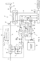
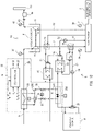
- FIG. 1 is a block diagram showing a schematic configuration of a gas engine system 1 according to Embodiment 1 of the present invention.
- the gas engine system 1 of the present embodiment includes a gas engine 2, an electricity generator 3, a turbocharger 4, a charge air cooler 5, and an intake air temperature regulator 6.
- fuel gas is supplied into a non-illustrated cylinder through a non-illustrated fuel pipe, and charge air is supplied into the cylinder through a charge air path 7.
- An air-fuel mixture made up of the fuel gas and charge air is compressed, combusted, and expanded in the cylinder, and along with this cycle the cylinder is reciprocated to produce drive power.
- the gas engine 2 includes not a single cylinder but two or more cylinders. The cylinders are coupled through one shaft such that asynchronous reciprocation of the cylinders is converted into rotation.
- the fuel gas supplied to the gas engine 2 is, for example, natural gas.
- the electricity generator 3 is connected to the gas engine 2 and configured to generate electricity using the rotational power of the gas engine 2.
- the turbocharger 4 draws, from outside, intake air to be supplied to the gas engine 2, compresses the intake air to a pressure required in the gas engine 2 by using a compressor 10, and supplies the high-pressure air as charge air to the cylinders of the gas engine 2.
- the combustion gas discharged from the gas engine 2 is expanded by a turbine 11, and the resulting power is used to rotate the compressor 10.
- the compressor 10 and turbine 11 are connected by a rotating shaft 9 to enable the power transmission.
- the compressor 10 includes compressor blades mounted at a blade angle suitable for the operation requirements of the gas engine 2 used.
- An intake air introducer 8 may be configured to introduce atmospheric air outside a building (outdoor air) or air inside the building (indoor air).
- the intake air introducer 8 may be configured to switch between taking in the outdoor air directly and using the indoor air per se as intake air depending on the outdoor air temperature.
- the intake air compressed by the compressor 10 is supplied as the charge air to the gas engine 2 through the charge air path 7.
- intake air refers to the air introduced from the intake air introducer 8 into the turbocharger 4
- charge air refers to the air flowing from the outlet of the compressor 10 of the turbocharger 4 and supplied to the gas engine 2.
- the combustion in the gas engine 2 produces drive power, and the high-temperature combustion gas discharged from the gas engine 2 flows into the turbine 11 of the turbocharger 4 through a discharge path 12.
- the turbine 11 includes turbine blades.
- the turbine 11 expands the high-temperature combustion gas flowing into the turbine 11, thereby producing drive power.
- the drive power is transmitted to the compressor 10 through the rotating shaft 9, and thus the compressor 10 is rotated.
- the exhaust gas discharged from the turbine 11 is directed to a chimney 13 through an exhaust gas path 43 and discharged to the atmosphere from the chimney 13.
- Exhaust heat recovery equipment 45 that recovers exhaust heat of the exhaust gas may be disposed in the exhaust gas path 43.
- the exhaust gas coming out of the gas engine 2 and passing through the turbine 11 has a high temperature, and the exhaust heat can be recovered in the form of steam or hot water and used in other applications, including building heating, district heating, and a heat source of cooling water-producing equipment such as a chiller.
- the exhaust heat recovery equipment 45 recovers the exhaust heat of the exhaust gas in the form of steam or hot water.
- the charge air cooler 5 is configured to cool the charge air compressed by the compressor 10 of the turbocharger 4 using the following two types of cooling water: high-temperature cooling water used to cool the gas engine 2 and having a relatively high temperature; and low-temperature cooling water supplied from equipment that performs cooling water production by dissipating heat to the atmosphere and having a relatively low temperature.
- the charge air cooler 5 includes a first charge air cooler 14 and a second charge air cooler 15. The first charge air cooler 14 is disposed upstream of the second charge air cooler 15 in the charge air path 7 between the turbocharger 4 and the gas engine 2.
- the charge air temperature resulting from cooling by the first charge air cooler 14 is higher than the charge air temperature resulting from cooling by the second charge air cooler 15.
- the first cooling water having passed through the first charge air cooler 14 has a higher temperature than the second cooling water having passed through the second charge air cooler 15.
- the first cooling water supplied to the first charge air cooler 14 may have a higher temperature than the second cooling water supplied to the second charge air cooler 15.
- the first charge air cooler 14 is disposed in a portion of a first cooling water path 16 for cooling of the gas engine 2, the portion being a return path from the gas engine 2. That is, the first charge air cooler 14 cools the charge air using the first cooling water having cooled the gas engine 2.
- the second charge air cooler 15 is disposed in a second cooling water path 17 different from the first cooling water path 16 for cooling of the gas engine 2. This configuration ensures a cooling scheme by which the high-temperature charge air at the outlet of the compressor 10 of the turbocharger 4 can be cooled to a charge air temperature suitable for supply to the gas engine.
- the charge air cooler 5 includes a cooling source 18.
- the cooling source 18 is configured as a cooling tower or radiator that performs cooling using heat of evaporation.
- the cooling source 18 is connected to the second cooling water path 17 and cools the second cooling water flowing through the second cooling water path 17 by means of atmospheric air.
- a pump 19 for circulation of the second cooling water is disposed in a feed path of the second cooling water path 17 that leads from the cooling source 18 to the second charge air cooler 15.
- a heat exchanger 20 is disposed in a return path of the second cooling water path 17 that leads from the second charge air cooler 15 to the cooling source 18.
- the heat exchanger 20 effects heat exchange with the first cooling water path 16 to cool the first cooling water.
- the heat exchanger 20 allows the remaining heat to be dissipated to the atmosphere from the cooling source 18 through heat exchange with the second cooling water.
- a heat exchanger that effects heat exchange with a lubrication path through which a lubricating oil for the gas engine 2 flows may be disposed between the second charge air cooler 15 and heat exchanger 20 in the second cooling water path 17 to cool the lubricating oil.
- a three-way valve 21 may be disposed between the feed and return paths in the second cooling water path 17 to reintroduce part of the second cooling water from the return path into the feed path.
- the amount of the second cooling water reintroduced is regulated by the three-way valve 21, and thus the temperature of the second cooling water (the cooling temperature of the second charge air cooler 15) is regulated. That is, the three-way valve 21 serves to stabilize the temperature of the second cooling water supplied to the second charge air cooler 15.
- the temperature t cw of the second cooling water supplied from the cooling source 18, which would decrease in the case where the atmospheric temperature is low, is maintained at a specified temperature by the three-way valve 21.
- a three-way valve 52 is disposed downstream of the three-way valve 21 in the second cooling water path 17.
- the three-way valve 52 controls the amount of the second cooling water flowing into the second charge air cooler 15 and thus controls the charge air temperature t 2 .
- the temperature t cw of the second cooling water supplied from the cooling source 18 is equal to or higher than the specified temperature; thus, the control function of the three-way valve 52 is disabled to allow all of the second cooling water having a temperature higher than the specified temperature to flow into the second charge air cooler 15.
- the first cooling water flowing through the first charge air cooler 14 is finally conditioned to a temperature required for engine cooling as a result of heat exchange with the heat exchanger 20 and control by a three-way valve 23 of the rate of flow into the heat exchanger 20.
- all of extra exhaust heat carried by the first cooling water having cooled the charge air in the first charge air cooler 14, or that portion of the extra exhaust heat which remains after heat recovery, is dissipated to the atmosphere from the cooling source 18 indirectly through the second cooling water path 17.
- a pump 22 for circulation of the first cooling water is disposed in a feed path of the first cooling water path 16 that leads from the heat exchanger 20 to the gas engine 2.
- a three-way valve 51 is disposed between the feed and return paths in the first cooling water path 16 to reintroduce part of the first cooling water from the return path into the feed path.
- the three-way valve 51 controls the flow rate of the first cooling water flowing into the exhaust heat recovery equipment 44 described later, and thus controls the amount of exhaust heat recovered by the exhaust heat recovery equipment 44.
- a charge air temperature detection sensor 24 that detects the temperature (charge air temperature) t 2 of the charge air supplied to the gas engine 2 is disposed downstream of the second charge air cooler 15 in the charge air path 7.
- Anon-illustrated controller of the charge air cooler 5 controls the opening degree of the three-way valve 52 such that the charge air temperature t 2 detected by the charge air temperature detection sensor 24 is a predetermined target temperature t s2 .
- the charge air cooler 5 carries out control for adjusting the charge air temperature t 2 to the target temperature t s2 .
- the degree of cooling depends on the atmospheric temperature or relative humidity, and this makes it almost impossible to cool the cooling water below the atmospheric temperature.
- the charge air temperature t 2 can be increased by using the three-way valve 52 to control the amount of the cooling water flowing into the second charge air cooler 15.
- there is generally an upper limit of the charge air temperature t 2 because of design constraints on the heat exchangers and limitations to the control range of the three-way valve 52.
- the charge air temperature t 2 is difficult to decrease in the case where the temperature t cw of the cooling water supplied from the cooling source 18 is high, even if the three-way valve 52 is bypassed to allow all of the second cooling water to flow into the second charge air cooler 15.
- the gas engine system 1 of the present embodiment includes the intake air temperature regulator 6 that regulates the temperature (intake air temperature) t 1 of intake air supplied to the turbocharger 4 from the intake air introducer 8 that draws in atmospheric air.
- the intake air temperature regulator 6 includes exhaust heat recovery equipment 44, a temperature regulator 25, and a controller 26.
- the exhaust heat recovery equipment 44 recovers exhaust heat generated in the gas engine 2 and first charge air cooler 14 in the form of hot water.
- the exhaust heat recovery equipment 44 is disposed downstream of the first charge air cooler 14 in the return path of the first cooling water path 16.
- the exhaust heat recovery equipment 44 is configured as a heat exchanger, and effects heat exchange with the first cooling water to recover the exhaust heat in the form of hot water.
- the three-way valve 51 is regulated to allow all of the first cooling water to flow into the exhaust heat recovery equipment 44.
- the temperature regulator 25 regulates the intake air temperature t 1 using the exhaust heat recovered by the exhaust heat recovery equipment 44.
- the temperature regulator 25 includes: a cooling water cooler 27 that cools cooling water (intake air cooling water) for cooling of the intake air using the exhaust heat recovered by the exhaust heat recovery equipment 44; and a cooling pipe 28 through which the cooling water coming from the cooling water cooler 27 is supplied to the intake air introducer 8.
- the cooling water cooler 27 is configured as a hot water absorption chiller that cools the cooling water using the hot water resulting from heat recovery by the exhaust heat recovery equipment 44.
- the cooling water cooler 27 cools the intake air cooling water flowing through the cooling pipe 28 by means of evaporation heat resulting from evaporation of a first refrigerant (not shown) circulating in the cooling water cooler.
- the first refrigerant evaporated into water vapor is absorbed into a second refrigerant (not shown) such as lithium bromide.
- the second refrigerant diluted as a result of absorption of the first refrigerant is heated with exhaust heat recovered by the exhaust heat recovery equipment 44 and restored to the pre-absorption concentration.
- Water vapor generated from the second refrigerant as a result of heating of the second refrigerant is cooled, for example, by a cooling source (not shown) and condensed into the first refrigerant in a liquid form.
- the cooling water for cooling of the intake air can be easily cooled by means of exhaust heat-recovering hot water regardless of the atmospheric temperature.
- a circulation pump disposed at a suitable location for hot water circulation, although this pump is omitted in FIG. 1 .
- the cooling water cooler 27 may be configured as a steam absorption chiller rather than as the hot water absorption chiller as described above.
- the exhaust heat recovery equipment 45 disposed in the exhaust gas path 43 is used as exhaust heat recovery equipment for cooling the intake air, and the cooling water cooler 27 produces cold water using steam resulting from heat recovery by the exhaust heat recovery equipment 45.
- the heat exchanger 44 need not be used to cool the intake air cooling water. Hot water resulting from heat recovery by the heat exchanger 44 may be used, for example, as a heat source for district heating.
- the cooling pipe 28, through which the intake air cooling water flows, is connected to a heat exchanger 30 disposed in an intake air path 29 through which the intake air introduced from the intake air introducer 8 flows.
- the heat exchanger 30 allows the intake air cooling water flowing through the cooling pipe 28 to exchange heat with the intake air flowing through the intake air path 29, thereby cooling the intake air.
- a circulation pump disposed at a suitable location for circulation of the intake air cooling water, although this pump is omitted in FIG. 1 .
- a three-way valve 31 that regulates the flow rate of the intake air cooling water flowing into the heat exchanger 30 may be disposed between the feed path leading from the cooling water cooler 27 to the heat exchanger 30 and the return path leading from the heat exchanger 30 to the cooling water cooler 27.
- the temperature of the intake air cooling water (the temperature of the intake air introduced from the intake air introducer 8) is regulated by using the three-way valve 31 to allow part of the intake air cooling water to flow from the feed path into the return path. That is, the three-way valve 31 functions as a temperature regulating component of the temperature regulator 25.
- the three-way valve 31 as described above need not be disposed, and all of the cooling water coming from the cooling water cooler 27 may be supplied to the heat exchanger 30.
- one way of regulating the intake air temperature t 1 may be to control the temperature of the cooling water supplied from the cooling water cooler 27 to the heat exchanger 30 and thus indirectly control the amount of heat exchange in the heat exchanger 30.
- the controller 26 controls the temperature regulator 25.
- the controller 26 is configured, for example, by a computer such as a microcontroller, a memory (storage), and/or electronic circuitry.
- An intake air temperature detection sensor 32 that detects the temperature t 1 (hereinafter referred to as "intake air temperature”) of the intake air supplied to the turbocharger 4 is disposed in the intake air path 29 (between the heat exchanger 30 and the turbocharger 4).
- the controller 26 acquires the intake air temperature t 1 from the intake air temperature detection sensor 32 and acquires, from the charge air temperature detection sensor 24, the temperature t 2 (hereinafter referred to as "charge air temperature”) of the charge air supplied to the gas engine 2.
- the controller 26 controls the intake air temperature t 1 such that the charge air temperature t 2 is a predetermined target temperature t s2 .
- the storage stores data of the intake air temperature t 1 for controlling the charge air temperature t 2 to the target temperature t s2 (data of the target temperature t s1 of the intake air temperature t 1 that is associated with the target temperature t s2 of the charge air temperature t 2 ).
- data is determined based on factors such as the performances of the turbocharger 4 and charge air cooler 5.
- the controller 26 Upon acquiring the charge air temperature t 2 , the controller 26 retrieves the data of the intake air temperature t 1 for controlling the temperature t 2 to the target temperature t s2 and, based on the retrieved data, generates an opening degree command value indicating the opening degree to which the three-way valve 31 should be controlled in order to adjust the intake air temperature t 1 to the target temperature t s1 .
- the controller 26 transmits a control signal S1 containing the generated opening degree command value to the three-way valve 31, thereby controlling the opening degree of the three-way valve 31. In this manner, the temperature of the intake air cooling water flowing through the heat exchanger 30 which effects heat exchange with the intake air is controlled (feedforward control and feedback control) such that the intake air temperature t 1 is adjusted to the target temperature t s1 .
- the temperature t 1 of the intake air supplied to the turbocharger 4 is regulated using exhaust heat generated in the gas engine 2 which is cooled using cooling water cooled with atmospheric air.
- the regulation of the intake air temperature t 1 is such that the temperature t 2 of the charge air supplied to the gas engine 2 is the predetermined target temperature t s2 .
- the charge air temperature t 2 can be controlled to the target temperature t s2 regardless of atmospheric conditions.
- the temperature regulator 25 includes the cooling water cooler 27 for cooling the intake air.
- the cooling water cooler 27 for cooling the intake air.
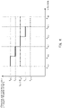
- FIG. 2 shows a schematic graph showing the relationships of the intake air temperature and charge air temperature with the atmospheric temperature during the control of Embodiment 1.
- the atmospheric temperature in the graph of FIG. 2 is an example of average monthly temperatures during one year in a geographical region in which the gas engine system 1 is installed.
- the above-described control for cooling the intake air is not performed in winter (period in which the atmospheric temperature is lower than a reference temperature t c1 and equal to or higher than a minimum intake air temperature t 1min for the turbocharger 4).
- the charge air temperature t 2 is maintained at the target temperature t s2 by the charge air cooler 5.
- the intake air temperature regulator 6 carries out the control for cooling the intake air in the event that the second cooling water temperature t cw increases and accordingly the charge air temperature t 2 exceeds the target temperature t s2 . Thanks to this control, the intake air temperature t 1 is maintained at the reference temperature t c1 regardless of the atmospheric temperature, and the charge air temperature t 2 is maintained at the target temperature t s2 .
- the charge air temperature t 2 can be regulated to the target temperature t s2 by using the three-way valve 52 even in the case where the second cooling water temperature t cw is above the reference temperature. In this case, control may be performed which further decreases the intake air temperature t 1 by allowing all of the cooling water supplied from the cooling water cooler 27 to flow into the heat exchanger 30.
- the exhaust heat is recovered in the return path of the first cooling water path 16, so that the temperature of the hot water resulting from heat exchange is higher than otherwise.
- This allows the cooling water cooler 27 to produce cooling water more efficiently and thus the intake air temperature t 1 to be regulated over a wider temperature range.
- the control of the intake air temperature t 1 allows the charge air temperature t 2 to be maintained at the target temperature t s2 without being affected by the atmospheric temperature, and this can ensure that the intake air temperature t 1 is also maintained in a given range.
- the range of variations in the intake air temperature t 1 can be narrowed.
- the volume flow rate of the required intake air compressed by the compressor 10 of the turbocharger 4 can be reduced while the weight flow rate of the intake air compressed by the compressor 10 remains the same. This makes it possible for the permissible range of the intake air temperature t 1 in the turbocharger 4 to be considerably narrower than in the case where the atmospheric air is directly drawn into the turbocharger 4.
- the design of the compressor blades and their mounting angle (including the choice of the number of the compressor blades) of the turbocharger 4 which is conventionally a general-purpose turbocharger designed to compress the required intake air over a wide range of intake air temperatures, can be specialized for the narrowed permissible range of variations in the intake air temperature t 1 . This can increase the efficiency of the adiabatic compression in the compressor 10 of the turbocharger 4.
- the charge air temperature t 2 is stabilized at the target temperature t s2 regardless of the atmospheric temperature, and accordingly the mixing ratio of the charge air and the fuel is also stabilized.
- the combustion in the gas engine 2 takes place in an optimal state.
- the temperature t 3 of the combustion gas discharged from the gas engine 2 is also stabilized, and the range of variations in the combustion gas temperature t 3 is narrower than in the case where the charge air temperature t 2 varies significantly with changing atmospheric temperature.
- the turbocharger 4 can be designed differently from a conventional general-purpose turbocharger which is designed, with the emphasis on versatility, to expand combustion gas with a wide range of high temperatures and produce drive power.
- on-off valves 33 are disposed in the cooling pipe 28. Additionally, on-off valves 34 are disposed in a pipe between the exhaust heat recovery equipment 44 and the cooling water cooler 27. The on-off valves 33 and 34 are closed to block the flow of the fluid (such as cooling water) through the pipes in the case where cooling of the intake air is not needed.
- the fluid such as cooling water
- the charge air temperature t 2 can be maintained at the target temperature t s only by charge air cooling performed by the charge air cooler 5 using atmospheric air, while cooling of the intake air is needed in summer since the charge air temperature t 2 cannot be maintained at the target temperature t s2 only by the cooling performed by the charge air cooler 5.
- the on-off valves 33 and 34 are opened to permit the flow of the fluid in summer, while in winter, the on-off valves 33 and 34 are closed to block the flow of the fluid.
- extra exhaust heat can be recovered by the exhaust heat recovery equipment 44 and used for another purpose such as building heating.
- the pipe through which hot water resulting from heat recovery by the exhaust heat recovery equipment 44 is delivered to an external entity is omitted in FIG. 1 .
- the controller 26 is configured to transmit, to the on-off valves 33 and 34, switch signals S2 for opening and closing the on-off valves 33 and 34.
- the switch signals S2 may be generated based on inputs provided by the operator. Alternatively, the controller 26 may automatically generate the switch signals S2 based on the set period. Alternatively, the controller 26 may acquire the outdoor air temperature and automatically generate the switch signals S2 based on the acquired outdoor air temperature.
- the controller 26 need not control the opening and closing of the on-off valves 33 and 34, and a facility operator may directly open or close the on-off valves 33 and 34.
- the on-off valves 33 and 34 need not be used, for example, in the case where intake air cooling is performed throughout the year.
- the target temperature t s2 of the charge air temperature t 2 may be set to different values depending on the properties (such as the methane number F MN and calorie F CAL ) of the fuel gas.
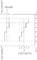
- FIG. 3 is a graph showing an example of the relationship of the target temperature t s2 of the charge air temperature t 2 with the methane number F MN of the fuel gas.
- the magnitude relationship of the values of the methane number F MN is as follows: F MN0 ⁇ F MN1 ⁇ ... ⁇ F MN5 .
- the target temperature t s2 of the charge air temperature T 2 is set higher as the methane number F MN of the fuel gas increases.
- FIG. 3 the target temperature t s2 of the charge air temperature T 2 is set higher as the methane number F MN of the fuel gas increases.
- the range of the methane number F MN is divided into a plurality of levels (five levels), and different target temperatures t s2-0 to t s2-4 are set for the different levels.
- the range of the methane number F MN may be divided into a greater number of levels, and different target temperatures t s2 may be set for the greater number of levels.
- the range of the methane number F MN may be divided into a smaller number of levels, and different target temperatures t s2 may be set for the smaller number of levels.
- the levels of the methane number F MN are defined at regular intervals.
- the levels of the methane number F MN may be defined at any intervals (at varying intervals).
- the methane number range from F MN1 to F MN5 is a range over which the gas engine 2 can operate at rated output.
- the methane number range over which the gas engine 2 can operate at rated output is divided into four levels (F MN1 to F MN2 : first level, F MN2 to F MN3 : second level, F MN3 to F MN4 : third level, F MN4 to F MN5 : fourth level), and target temperatures t s2-1 to t s2-4 are set for the four levels, respectively.
- the methane number F MN0 is the minimum methane number for use as the fuel of the gas engine 2.
- the methane number range from F MN0 to F MN1 is a range over which the gas engine 2 can operate at reduced output.
- the intake air temperature t 1 may be controlled also during the operation of the gas engine 2 at reduced output.
- the target temperature of the charge air temperature t 2 is set to t s2-0 .
- the methane number F MN is calculated at given times from gas composition-related parameters of the fuel gas.
- FIG. 4 is a graph showing an example of the relationship of the target temperature t s2 ' of the charge air temperature t 2 with the calorie F CAL of the fuel gas.
- the magnitude relationship of the values of the calorie F CAL of the fuel gas is as follows: F CAL0 ⁇ F CAL1 ⁇ ... ⁇ F CAL5 .
- the methane number F MN and calorie F CAL of the fuel gas are correlated with each other to a certain extent. That is, the higher the calorie F CAL of the fuel gas is, the lower the methane number F MN is.
- the values F CAL0 , F CAL1 , ..., and F CAL5 of the calorie in FIG. 4 substantially correspond to the values F MN5 , F MN4 , ..., and F MN0 of the methane number in FIG. 3 , respectively.
- the target temperature t s2 ' of the charge air temperature t 2 may be set lower as the calorie F CAL of the fuel gas increases.
- the range of the calorie F CAL is divided into a plurality of levels (five levels: F CAL0 to F CAL1 , F CAL1 to F CAL2 , F CAL2 to F CAL3 , F CAL3 to F CAL4 , and F CAL4 to F CALS ), and different target temperatures t s2-0 ' to t s2-4 ' are set for the different levels.
- the range of the calorie F CAL of the fuel gas may be divided into a greater number of levels, and different target temperatures t s2 ' may be set for the greater number of levels.
- the range of the calorie F CAL of the fuel gas may be divided into a smaller number of levels, and different target temperatures t s2 ' may be set for the smaller number of levels.
- the levels of the calorie F CAL of the fuel gas are defined at regular intervals.
- the levels of the calorie F CAL may be defined at any intervals (at varying intervals).
- the air-fuel ratio that enables operation at a maximum efficiency point is determined based on the methane number F MN or calorie F CAL of the fuel gas.
- controlling the charge air temperature t 2 to the target temperature t s2 or t s2 ' appropriate for the methane number F MN or calorie F CAL of the fuel gas allows the gas engine 2 to operate at a maximum efficiency point.
- the target temperature t s2 or t s2 ' of the charge air temperature t 2 may be set to a predetermined target temperature t s2o (e.g., a temperature equal to t s2-2 or t s2-2 ')-
- the properties of the fuel supplied to the gas engine 2 and the combustion gas temperature t 3 are correlated with the charge air temperature t 2 . That is, in the case where the properties of the fuel are stable and change little, the charge air temperature t 2 is maintained substantially at the target temperature t s2 by controlling the intake air temperature t 1 such that the combustion gas temperature t 3 is the target temperature t s3 .
- acquiring the combustion gas temperature t 3 instead of the charge air temperature t 2 and controlling the intake air temperature t 1 such that the combustion gas temperature t 3 is the target temperature t s3 provides the same effect as acquiring the charge air temperature t 2 and controlling the intake air temperature t 1 such that the charge air temperature t 2 is the target temperature t s2 .
- the target temperature t s3 may be settable according to the properties of the fuel gas supplied to the gas engine 2.
- the control is performed based on signals acquired from both the charge air temperature detection sensor 24 and combustion gas temperature detection sensor 39, the operation may be continued using only the signal from one of the temperature detection sensors during a period in which the other temperature detection sensor is out of order.
- the controller 26 may acquire both the charge air temperature t 2 and combustion gas temperature t 3 and monitor the operation state of the gas engine 2 by comparing each of the acquired temperatures with a corresponding one of predetermined target temperatures.
- the configuration of the charge air cooler 5 is not limited to that in Embodiment 1.
- a heat exchanger e.g., a radiator
- FIG. 5 shows a schematic configuration of a gas engine system 1A according to Variant 1 of Embodiment 1 of the present invention.
- the elements which are the same as those of FIG. 1 are denoted by the same reference signs in FIG. 5 and will not be described again.
- FIG. 5 illustrates an example where the charge air cooler includes two radiators 35 and 36 as heat exchangers.
- the charge air cooler 5A includes the radiators 35 and 36 that respectively cool the first cooling water and second cooling water which respectively flow through the two charge air coolers 14 and 15.
- the first radiator 35 is connected to a first cooling water path 16A and supplies the first cooling water to the first charge air cooler 14 via the gas engine 2, thus cooling the charge air at the outlet of the turbocharger 4.
- the second radiator 36 is connected to a second cooling water path 17A and supplies the second cooling water to the second charge air cooler 15, thus cooling the charge air leaving the first charge air cooler 14.
- the first and second cooling water paths 16A and 17A are configured independently of each other (these two paths cannot exchange heat with each other).
- the cooling capacities of the radiators 35 and 36 are individually defined such that the first cooling water dissipates heat collected in the gas engine 2 and first charge air cooler 14 to the atmosphere, the second cooling water dissipates heat collected in the second charge air cooler 15 and a non-illustrated oil cooler to the atmosphere, and the gas engine system operates without any trouble.
- the first cooling water path 16A allows the first cooling water to flow from the first radiator 35 into the first charge air cooler 14 via the gas engine 2.
- Athree-way valve 23A is disposed between the feed and return paths in the first cooling water path 16A to reintroduce part of the first cooling water from the return path into the feed path and regulate the temperature of the first cooling water.
- the exhaust heat recovery equipment 44 is disposed between the first charge air cooler 14 and the three-way valve 23A.
- the three-way valve 51 serves to regulate the amount of heat recovered by the exhaust heat recovery equipment 44.
- the second cooling water path 17A allows the second cooling water to flow from the second radiator 36 into the second charge air cooler 15.
- Three-way valves 21A and 52 are disposed between the feed and return paths in the second cooling water path 17A to reintroduce part of the second cooling water from the return path into the feed path and regulate the temperature of the second cooling water.
- the three-way valve 52 serves to control the amount of the cooling water flowing into the second charge air cooler 15 such that the charge air temperature t 2 is the target temperature t s2 .
- the intake air temperature regulator 6 that cools the intake air using exhaust heat recovered by the exhaust heat recovery equipment 44 can be employed as in Embodiment 1.
- Embodiment 1 ( FIG. 1 ) and the variant shown in FIG. 5 , a configuration has been illustrated in which the first charge air cooler 14 cools the charge air at the outlet of the turbocharger 4 using cooling water having cooled the gas engine 2 in the first cooling water path 16.
- cooling water may be supplied to the first charge air cooler from the cooling source 18 or heat exchanger (radiator 36) without passage through the cooling path for the gas engine 2 in the same manner as cooling water is supplied to the second charge air cooler.
- FIG. 6 shows a schematic configuration of a gas engine system 1F according to Variant 2 of Embodiment 1 of the present invention.
- a charge air cooler 5F includes a charge air cooling water path 56F through which cooling water is supplied to each of first and second charge air coolers 14F and 15F and a gas engine cooling path 54F disposed separately from the charge air cooling water path 56F to cool the gas engine 2.
- the charge air cooling water path 56F includes a first cooling water path 16F through which the cooling water coming from the cooling source 18 is supplied to the first charge air cooler 14F and a second cooling water path 17F through which the cooling water coming from the cooling source 18 is supplied to the second charge air cooler 15F.
- the first and second cooling water paths 16F and 17F are arranged in parallel.
- a third cooling water path 53F is connected to the cooling source 18, and the first and second cooling water paths 16F and 17F branch from the third cooling water path 53F.
- the heat exchanger 20 that effects heat exchange with the gas engine cooling path 54F for cooling the gas engine 2 is disposed in the return path of the third cooling water path 53F.
- the exhaust heat recovery equipment 44 is disposed downstream of the gas engine 2 in the gas engine cooling path 54F and recovers exhaust heat generated in the gas engine 2 in the form of hot water. That is, in this variant, the high-temperature cooling water having cooled the gas engine 2 does not pass through the first charge air cooler 14F, and exhaust heat recovery and exhaust heat dissipation to the atmosphere are accomplished by the exhaust heat recovery equipment 44 and the heat exchanger 20.
- the three-way valve 51 serves to regulate the amount of heat recovered by the exhaust heat recovery equipment 44.
- the three-way valve 52 serves to control the amount of cooling water flowing into the second charge air cooler 15 such that the charge air temperature t 2 is the target temperature t s2 .
- the charge air temperature t 2 can be controlled to the target temperature t s2 regardless of atmospheric conditions.
- the charge air cooling water path 56F for cooling the charge air and the gas engine cooling path 54F for cooling the gas engine 2 are separate from each other.
- the charge air temperature t 2 is easily controlled to the target temperature t s2 even in the event that the intake air temperature t 1 is lower and accordingly the intake air temperature at the outlet of the compressor 10 of the turbocharger 4 is lower than in the case where the first charge air cooler is disposed downstream of the gas engine 2 in the cooling path for the gas engine 2 as in the example of FIG. 1 (the first cooling water path 16 in FIG. 1 ).
- the charge air temperature t 2 can be regulated by the first and second charge air coolers 14F and 15F over a wider temperature range.
- FIG. 7 shows a schematic configuration of a gas engine system 1G according to Variant 3 of Embodiment 1 of the present invention.
- the elements which are the same as those of FIG. 5 are denoted by the same reference signs in FIG. 7 and will not be described again.
- a charge air cooler 5G in this variant like the charge air cooler in the example of FIG. 5 , includes the two radiators 35 and 36 as heat exchangers.
- the charge air cooler 5G in this variant like the charge air cooler in the example of FIG. 6 , includes a charge air cooling water path 56G through which cooling water is supplied to each of first and second charge air coolers 14G and 15G and a gas engine cooling path 54G disposed separately from the charge air cooling water path 56G to cool the gas engine 2.
- the charge air cooling water path 56G in this variant includes a first cooling water path 16G through which the cooling water coming from the second radiator 36 is supplied to the first charge air cooler 14G and a second cooling water path 17G through which the cooling water coming from the second radiator 36 is supplied to the second charge air cooler 15G.
- the first and second cooling water paths 16G and 17G are arranged in parallel.
- a third cooling water path 53G is connected to the second radiator 36, and the first and second cooling water paths 16G and 17G branch from the third cooling water path 53G.
- the gas engine cooling path 54G for cooling the gas engine 2 is connected to the first radiator 35.
- the exhaust heat recovery equipment 44 is disposed downstream of the gas engine 2 in the gas engine cooling path 54G and recovers exhaust heat generated in the gas engine 2 in the form of hot water. That is, in this variant, the high-temperature cooling water having cooled the gas engine 2 does not pass through the first charge air cooler 14F, and exhaust heat recovery and exhaust heat dissipation to the atmosphere are accomplished by the exhaust heat recovery equipment 44 and the first radiator 35.
- the three-way valve 51 serves to regulate the amount of heat recovered by the exhaust heat recovery equipment 44.
- the three-way valve 52 serves to control the amount of cooling water flowing into the second charge air cooler 15 such that the charge air temperature t 2 is the target temperature t s2 .
- the charge air temperature t 2 can be controlled to the target temperature t s2 regardless of atmospheric conditions.
- the charge air cooling water path 56G for cooling the charge air and the gas engine cooling path 54G for cooling the gas engine 2 are separate from each other.
- the charge air temperature t 2 is easily controlled to the target temperature t s2 even in the event that the intake air temperature t 1 is lower and accordingly the intake air temperature at the outlet of the compressor 10 of the turbocharger 4 is lower than in the case where the first charge air cooler is disposed downstream of the gas engine 2 in the cooling path for the gas engine 2 as in the example of FIG. 5 (the first cooling water path 16A in FIG. 5 ).
- the charge air temperature t 2 can be regulated by the first and second charge air coolers 14G and 15G over a wider temperature range.
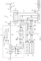
- FIG. 8 is a block diagram showing a schematic configuration of a gas engine system 1B according to Embodiment 2 of the present invention.
- the elements which are the same as those of FIG. 5 are denoted by the same reference signs in FIG. 8 and will not be described again.
- the gas engine system 1B of the present embodiment differs from the gas engine system of Embodiment 1 in that a temperature regulator 25B of an intake air temperature regulator 6B has the function of increasing the intake air temperature t 1 as well as the function of decreasing the intake air temperature t 1 .
- the gas engine system 1B of the present embodiment includes the radiators 35 and 36 as heat exchangers of the charge air cooler 5A.
- the temperature regulator 25B includes a heating pipe 37 and a pipe switcher in addition to the cooling water cooler 27 and the cooling pipe 28.
- the heating pipe 37 supplies hot water coming from the exhaust heat recovery equipment 44 to the heat exchanger 30 disposed in the intake air introducer 8 to heat the intake air. That is, the heating pipe 37 is configured as a bypass path disposed between the exhaust heat recovery equipment 44 and the heat exchanger 30 (and the three-way valve 31) in the cooling pipe 28 to allow the hot water to bypass the cooling water cooler 27.
- the exhaust heat recovery equipment 44 may recover the maximum amount of exhaust heat in the case where the hot water resulting from the heat recovery is used in the cooling water cooler 27 (in the case of intake air cooling). In the case of intake air heating, the amount of hot water required is smaller than in the case of intake air cooling since the hot water temperature is high. Thus, the amount of the first cooling water flowing into the exhaust heat recovery equipment 44 is controlled by means of the three-way valve 51 to decrease the temperature of the hot water used for the intake air heating, and then the hot water is supplied to the heat exchanger 30 to heat the intake air.
- the pipe switcher switchably connects the cooling pipe 28 or the heating pipe 37 to the intake air introducer 8 (to the heat exchanger 30 of the intake air introducer 8).
- the pipe switcher includes the on-off valves 33 and 34 described in Embodiment 1 and on-off valves 38 disposed in the heating pipe 37. As in Embodiment 1, the opening and closing of the on-off valves 33 and 34 are controlled by the controller 26. The opening and closing of the on-off valves 38 are also controlled by the controller 26.
- the controller 26 outputs signals containing a first value (High) or a second value (Low), and such signals are transmitted to the on-off valves 33, 34, and 38 as switch signals S2.
- the on-off valves 33 and 34 are opened upon receiving the switch signal S2 containing the first value and closed upon receiving the switch signal S2 containing the second value.
- the on-off valves 38 are closed upon receiving the switch signal S2 containing the first value and opened upon receiving the switch signal S2 containing the second value.
- the switch signal for the on-off valves 33 and 34 and the switch signal for the on-off valves 38 may be different from each other.
- the intake air cooling water is supplied to the intake air introducer 8 to cool the intake air as in Embodiment 1.
- hot water produced using exhaust heat recovered by the exhaust heat recovery equipment 44 flows through the heating pipe 37 and is directly supplied to the intake air introducer 8 to heat the intake air.
- the amount of exhaust heat recovered by the exhaust heat recovery equipment 44 is controlled by means of the three-way valve 51 as described above. To this end, the switch signal S2 from the controller 26 is transmitted also to the three-way valve 51.
- the controller 26 controls the intake air temperature t 1 such that the temperature t 2 of the charge air supplied to the gas engine 2 is a predetermined target temperature t s2 .
- the value of the target temperature t s2 may vary between intake air cooling and intake air heating.
- the storage stores data of the target temperature t sc1 of the intake air temperature t 1 that is associated with the target temperature t sc2 of the charge air temperature t 2 in intake air cooling and further stores data of the intake air temperature t sh1 associated with the target temperature t sh2 in intake air heating.
- an apparent target temperature t sh2 of the charge air temperature t 2 that is used to set the target temperature t s1 of the intake air temperature t 1 in intake air heating may be set equal to or higher than the target temperature t sc2 in intake air cooling.
- the properties of the fuel gas may be input to the controller 26.
- the target temperature t sc2 in intake air cooling and the target temperature t sh2 in intake air heating are set to values appropriate for the input properties of the fuel gas.
- the target temperatures t s2 of the charge air temperature t 2 may be set to predetermined values.
- the controller 26 transmits a control signal also to the three-way valve 51 and thereby controls the three-way valve 51 such that an amount of exhaust heat sufficient for increasing the intake air temperature t 1 from the atmospheric temperature to the target temperature t sc1 is recovered by the exhaust heat recovery equipment 44.
- the controller 26 retrieves the data of the target temperature t sc1 to which the intake air temperature t 1 should be decreased to control the charge air temperature t 2 to the target temperature t sc2 , and carries out feedforward control and feedback control.
- the controller 26 calculates the amount of cooling water required for decreasing the intake air temperature t 1 to the target temperature t sc1 based on the atmospheric temperature, the humidity, and the amount of air prestored as data representing the amount of intake air in the gas engine 2, and transmits the calculated information to the three-way valve 31.
- the controller 26 finely regulates the amount of cooling water flowing into the heat exchanger 30 by means of the three-way valve 31 and based on data of the intake air temperature t 1 and charge air temperature t 2 which are obtained as a result of the feedforward control.
- the controller 26 retrieves data of the intake air temperature t sh1 for controlling the charge air temperature t 2 to the target temperature t sh2 , and carries out feedforward control and feedback control.
- the controller 26 calculates the amount of heat required for increasing the intake air temperature to the target temperature t sh1 based on the atmospheric temperature, the humidity, and the amount of air prestored as data representing the amount of intake air in the gas engine 2, and transmits the calculated information to the three-way valve 31.
- the controller 26 regulates the flow rate of hot water flowing into the exhaust heat recovery equipment 44 by means of the three-way valve 51 and based on data of the intake air temperature t 1 and charge air temperature t 2 which are obtained as a result of the feedforward control, and finely regulates the amount of the hot water flowing into the heat exchanger 30 by means of the three-way valve 31 and based on the data obtained as a result of the feedforward control.
- the target temperature t sh2 in intake air heating is merely an apparent target temperature of the charge air temperature t 2 that is set in the controller 26 to increase the intake air temperature t 1 , and the actual charge air temperature t 2 in intake air heating is controlled by the charge air cooler 5A to be equal to the target temperature t sc2 in intake air cooling (electricity generation efficiency priority mode).
- the apparent target temperature t sh2 of the charge air temperature t 2 on which the target temperature t s1 of the intake air temperature t 1 is based, is different from the target temperature t sc2 to which the charge air temperature t 2 is controlled by the charge air cooler 5A
- interference could occur between control of the intake air temperature t 1 by the controller 26 of the intake air temperature regulator 6 and control of the charge air temperature t 2 by the controller (not shown) of the charge air cooler 5.
- the control response of the charge air temperature t 2 controlled by the charge air cooler 5 may be slower than the control response of the intake air temperature t 1 controlled by the intake air temperature regulator 6.
- the intake air temperature t 1 is regulated by the control in the intake air temperature regulator 6 (the control of the three-way valve 31) such that the charge air temperature t 2 is adjusted to the apparent target temperature t sh2 , and then the charge air temperature t 2 is regulated to the final target temperature t sc2 by the control in the charge air cooler 5 (the control of the three-way valve 52).
- cooling water is produced by the cooling water cooler 27 using exhaust heat delivered from the charge air cooler 5A, and this cooling water can be used to allow the heat exchanger 30 to serve as an intake air cooler.
- the charge air temperature t 2 can be decreased to the target temperature t sc2 in intake air cooling even in summer or any other circumstances where the atmospheric temperature is so high that the charge air cooler 5 cannot by itself decrease the charge air temperature t 2 to the target temperature t sc2 .
- cooling pipe 28 through which cooling water flows or the heating pipe 37 through which hot water flows can be switchably connected to the intake air introducer 8. This allows the heat exchanger 30 to serve also as an intake air heater, making it also possible to increase the intake air temperature.
- the compressor 10 of the turbocharger 4 is designed as a general-purpose compressor.
- a minimum value of the intake air temperature is defined as a design constraint.
- the gas engine system cannot operate unless the intake air temperature is equal to or higher than the minimum value. This problem arises in the case where the atmospheric temperature is low, such as in winter.
- the conventional way of continuing the operation in such a case is to install complicated machinery including both outdoor air intake equipment that introduces outdoor air as the intake air and indoor air intake equipment that introduces indoor air as the intake air and configured to switch from outdoor air introduction through the outdoor air intake equipment to indoor air introduction through the indoor air intake equipment in the event of a decrease in the atmospheric temperature.
- the intake air temperature can be increased without using complicated machinery switchable from introduction of outdoor air as the intake air to introduction of indoor air as the intake air or without introducing indoor air as the intake air throughout the year. This makes it possible to control the charge air temperature t 2 to the target temperature t s2 while ensuring the design constraint of the compressor 10 of the turbocharger 4.
- the heat supply sources are the exhaust heat recovery equipment 44 and the exhaust heat recovery equipment 45 disposed in the exhaust gas path 43.
- the amount of heat recovered by the exhaust heat recovery equipment 45 increases as the exhaust gas temperature t 4 at the outlet of the turbine 11 of the turbocharger 4 becomes higher.
- the controller 26 can execute a heat recovery priority mode (second control mode) in which the target temperature of the charge air temperature t 2 is set to a target temperature for increasing the amount of recovered heat (second target temperature) instead of being set to a target temperature for high electricity generation efficiency (first target temperature) in the electricity generation efficiency priority mode (first control mode).
- second control mode a heat recovery priority mode in which the target temperature of the charge air temperature t 2 is set to a target temperature for increasing the amount of recovered heat (second target temperature) instead of being set to a target temperature for high electricity generation efficiency (first target temperature) in the electricity generation efficiency priority mode (first control mode).
- the target temperature of the charge air temperature t 2 in the electricity generation efficiency priority mode is denoted by t sq2 and the target temperature of the charge air temperature t 2 in the heat recovery priority mode is denoted by t sr2 .
- the target temperature t sq2 in the electricity generation efficiency priority mode includes the above-described target temperature t sc2 in intake air cooling and the above-described target temperature t sh2 in intake air heating. That is, in the case where the properties of the fuel gas are input to the controller 26, the target temperature t sq2 in the electricity generation efficiency priority mode is set to a value appropriate for the input properties of the fuel gas.
- the target temperature t sq2 in the electricity generation efficiency priority mode may be set to a predetermined value.
- the target temperature t sr2 in the heat recovery priority mode is set higher than the target temperature t sq2 in the electricity generation efficiency priority mode.
- the target temperature t sr2 in the heat recovery priority mode may be set to a constant value regardless of the properties of the fuel gas.
- the target temperature t sr2 in the heat recovery priority mode may be set to different values depending on the properties of the fuel gas.
- FIG. 9 is a graph showing examples of the relationships of the target temperatures t sq2 and t sr2 of the charge air temperature T 2 with the methane number F MN of the fuel gas in the two priority modes.
- the target temperature t sq2 of the charge air temperature t 2 in the electricity generation efficiency priority mode is set in the same manner as in the example of FIG. 3 . That is, the target temperatures t sq2-0 to t sq2-4 set for different levels (zeroth to fourth levels) of the methane number F MN in FIG. 9 correspond to the target temperatures t s2-0 to t s2-4 set for different levels (zeroth to fourth levels) of the methane number F MN in FIG. 3 .
- the target temperature t sr2 in the heat recovery priority mode is higher than the target temperature t sq2 in the electricity generation efficiency priority mode. That is, the target temperatures set for the different levels (zeroth to fourth levels) of the methane number F MN in the heat recovery priority mode are respectively higher than the target temperatures set for the different levels of the methane number F MN in the electricity generation efficiency priority mode.
- the target temperature t sr2 in the heat recovery priority mode is the same value (t sr2-1 ) for the zeroth level (F MNO to F MN1 ) and the first level (F MN1 to F MN2 ) and the same value (t sr2-3 ) for the third level (F MN2 to F MN3 ) and the fourth level (F MN3 to F MN4 ).
- the target temperature for the second level (F MN1 to F MN2 ) is t sr2-2 .
- the range of the methane number F MN is divided into a smaller number of levels (three levels) than in the electricity generation efficiency priority mode, and different target temperatures t sr2-1 to t sr2-3 are set for the three levels.
- the number of the levels into which the range of the methane number F MN is divided is smaller in the heat recovery priority mode than in the electricity generation efficiency priority mode.
- the number of the levels into which the range of the methane number F MN is divided may be the same (e.g., five levels) for both the electricity generation efficiency priority mode and the heat recovery priority mode or may be greater in the heat recovery priority mode than in the electricity generation efficiency priority mode.
- the methane number thresholds F MN2 and F MN3 at which the target temperature t sr2 is changed to different values in the heat recovery priority mode are set equal to the methane number thresholds F MN2 and F MN3 in the electricity generation efficiency priority mode.
- the methane number thresholds F MN2 and F MN3 at which the target temperature t sr2 is changed to different values in the heat recovery priority mode may be different from the methane number thresholds F MN2 and F MN3 in the electricity generation efficiency priority mode.
- the second level in the heat recovery priority mode may be a wider methane number range from a value below F MN2 to a value above F MN3 .
- FIG. 10 is a graph showing examples of the relationships of the target temperatures t s2 ' of the charge air temperature t 2 with the calorie F CAL of the fuel gas in the two priority modes.
- the target temperature t sq2 ' of the charge air temperature t 2 in the electricity generation efficiency priority mode is set in the same manner as in the example of FIG. 4 . That is, the target temperatures t sq2-0 ' to t sq2-4 ' set for different levels (zeroth to fourth levels) of the calorie F CAL in FIG. 10 correspond to the target temperatures t s2-0 ' to t s2-4 ' set for different levels (zeroth to fourth levels) of the calorie F CAL in FIG. 4 .
- the target temperature t sr2 ' in the heat recovery priority mode is set higher than the target temperature t sq2 ' in the electricity generation efficiency priority mode. That is, the target temperatures set for the different levels (zeroth to fourth levels) of the calorie F CAL in the heat recovery priority mode are respectively higher than the target temperatures set for the different levels of the calorie F CAL in the electricity generation efficiency priority mode.
- the range of the calorie F CAL is divided into a smaller number of levels (three levels) in the heat recovery priority mode than in the electricity generation efficiency priority mode, and different target temperatures t sr2-1 ' to t sr2-3 ' are set for the three levels.
- the control is performed to increase the intake air temperature t 1 such that the charge air temperature t 2 is the target temperature t sr2 which is higher than the target temperature t sq2 in the electricity generation efficiency priority mode, and the amount of cooling water flowing into the second charge air cooler 15 is regulated by means of the three-way valve 52 disposed in the second cooling water path 17A.
- the combustion gas temperature t 3 increases, and the exhaust gas temperature t 4 also increases. This leads to an increase in the amount of heat recovered by the exhaust heat recovery equipment 45 disposed in the exhaust gas path 43.
- the electricity generation efficiency is reduced since the target temperature of the charge air temperature t 2 is controlled to be higher than the target temperature t s2 for high electricity generation efficiency.
- the amount of the fuel supplied to the gas engine 2 is increased as a function of the reduction in electricity generation efficiency.
- the increase in the amount of exhaust heat recovered by the exhaust heat recovery equipment 44 is large relative to the increase in the amount of the fuel supplied to the gas engine .
- the total thermal efficiency of the entire system is improved although the electricity generation efficiency is reduced.
- the total thermal efficiency is defined herein by the following equation.
- Total thermal efficiency [%] ⁇ (electricity generator end output + amount of heat recovered from exhaust heat) / (amount of fuel input to gas engine 2) ⁇ ⁇ 100
- the controller 26 may set a target temperature t s1 to which the intake air temperature t 1 can be decreased from the atmospheric temperature by using cooling water produced in the cooling water cooler 27, and may regulate the three-way valve 52 to adjust the charge air temperature t 2 to the target temperature t s2 .
- This can reduce the amount of work required of the compressor 10 of the turbocharger 4, leading to improved electricity generation efficiency.
- the intake air temperature t 1 can be controlled over a wide range to achieve an optimal charge air temperature t 2 in response to various changes in outdoor air temperature.
- FIG. 11 is a schematic graph showing the relationships of the intake air temperature and charge air temperature with the atmospheric temperature during the control of Embodiment 2.
- FIG. 11 illustrates a case where the target temperature t s2 of the charge air temperature t 2 is constant regardless of the condition of the fuel gas.
- the atmospheric temperature in the graph of FIG. 11 is an example of average monthly temperatures during one year in a geographical region in which the gas engine system 1 is installed.
- the control for cooling the intake air is not performed during a period in which the atmospheric temperature is lower than a reference temperature t c1 and equal to or higher than a minimum intake air temperature t 1min for the turbocharger 4.
- the charge air temperature t 2 is maintained at the target temperature t s2 by the charge air cooler 5.
- the controller 26 may set a target temperature t s1 to which the intake air temperature t 1 can be decreased from the atmospheric temperature by using cooling water produced in the cooling water cooler 27, and may regulate the three-way valve 52 to adjust the charge air temperature t 2 to the target temperature t s2 . This can reduce the amount of work required of the compressor 10 of the turbocharger 4, leading to improved electricity generation efficiency.
- the control for cooling the intake air is carried out by the intake air temperature regulator 6B.
- the intake air temperature t 1 is controlled such that the charge air temperature t 2 is maintained at the target temperature t sq2 in the electricity generation efficiency priority mode regardless of the atmospheric temperature and the second cooling water temperature.
- the compressor 10 of the turbocharger 4 In winter, once the atmospheric temperature becomes equal to or lower than the minimum intake air temperature t 1min for the compressor 10 of the turbocharger 4, the compressor 10 of the turbocharger 4 cannot be operated due to the design constraint of the compressor 10 of the turbocharger 4 as described above if outdoor air is directly introduced as the intake air.
- the control for heating the intake air (electricity generation efficiency priority mode) is carried out by the intake air temperature regulator 6. Thanks to this control, the intake air temperature t 1 is maintained at a temperature t ic2 equal to or higher than the minimum intake air temperature t 1min regardless of the atmospheric temperature, and the compressor 10 of the turbocharger 4 can be operated by introduction of outdoor air.
- the temperature of the second cooling water for cooling in the second charge air cooler 15 is regulated to be always constant by means of the three-way valve 21A of the charge air cooler 5A, and the flow rate of the second cooling water flowing into the second charge air cooler 15 is regulated by means of the three-way valve 52.
- the charge air temperature t 2 of the charge air leaving the compressor 10 of the turbocharger 4 is maintained at the target temperature t sq2 in the electricity generation efficiency priority mode.
- the charge air temperature t 2 can be maintained at a temperature (t sq2 ) that allows for high electricity generation efficiency throughout the year.
- the heat recovery priority mode can be executed instead of the electricity generation efficiency priority mode.
- the target temperature t sr2 of the charge air temperature t 2 in the heat recovery priority mode is set to a temperature equal to, or lower than but close to, a maximum value (maximum charge air temperature) t 2max of the charge air temperature t 2 .
- the target temperature t 1c3 of the intake air temperature that is associated with the target temperature t sr2 needs to be equal to or lower than a maximum intake air temperature t 1max for the compressor 10 of the turbocharger 4.
- the target temperature t sr2 of the charge air temperature t 2 is set such that the target temperature t sr2 of the charge air temperature t 2 is equal to or lower than the maximum charge air temperature t 2max and the target temperature t 1c3 of the intake air temperature t 1 is equal to or lower than the maximum intake air temperature t 1max .
- the charge air temperature t 2 can be controlled to a temperature close to the maximum charge air temperature t 2max permissible for the gas engine 2, and thus the combustion gas temperature t 3 and the exhaust gas temperature t 4 can be increased as much as possible. Meanwhile, the intake air temperature t 1 is maintained at the temperature t 1c3 higher than the temperature t ic2 in the electricity generation efficiency priority mode regardless of the atmospheric temperature.
- Switching between the electricity generation efficiency priority mode and the heat recovery priority mode can be effected as appropriate.
- the atmospheric temperature is higher and the amount of hot water required for heating of a building or the like is smaller than in the night.
- the gas engine system is operated in the electricity generation efficiency priority mode, and hot water or steam resulting from exhaust heat recovery in the electricity generation efficiency priority mode is used for building heating or any other purpose.
- the amount of required hot water is greater than in the daytime since the atmospheric temperature decreases.
- the gas engine system is operated in the heat recovery priority mode which enables supply of a greater amount of hot water or steam.
- the heat recovery priority mode may be executed in summer or any other circumstances where the atmospheric temperature is high.
- the gas engine system is operated in the heat recovery priority mode during the daytime to recover a large amount of heat and produce a large amount of cold water which is needed for building cooling.
- the gas engine system is operated in a control mode where the amount of exhaust heat recovered is smaller than in the heat recovery priority mode (the electricity generation efficiency priority mode or another control mode where the intake air temperature control is not performed) since the amount of cold water used for building cooling is reduced.
- the charge air temperature t 2 is deliberately controlled not to the target temperature t s2 for high electricity generation efficiency but to a temperature higher than the target temperature t s2 .
- the exhaust gas temperature t 4 can be increased, and accordingly the amount of heat recovered from the gas engine system 1 can be increased. This can lead to an improvement in the total thermal efficiency of the entire gas engine system 1.
- the controller 26 may acquire the combustion gas temperature t 3 in addition to the charge air temperature t 2 . During the period in which one of the temperature detection sensors is out of order, the operation may be continued using only the signal from the other temperature detection sensor.
- the controller 26 may acquire both the charge air temperature t 2 and combustion gas temperature t 3 and monitor the operation state of the gas engine 2 by comparing each of the acquired temperatures with a corresponding one of predetermined target temperatures.
- the exhaust gas temperature t 4 may be acquired in addition to the charge air temperature t 2 .
- the exhaust gas temperature t 4 is an outlet temperature of the turbine 11 of the turbocharger 4 and detected by an exhaust gas temperature detection sensor 40.
- the controller 26 may acquire both the charge air temperature t 2 and exhaust gas temperature t 4 and monitor the operation state of the gas engine 2 by comparing each of the acquired temperatures t 2 and t 4 with a corresponding one of predetermined target temperatures t s2 and t s4 .
- Embodiment 2 a configuration has been illustrated in which the cooling and heating pipes 28 and 37 are disposed, and either of the cooling and heating pipes 28 and 37 can be switchably connected to the intake air introducer 8 to effect intake air cooling or intake air heating.
- the temperature regulator 25B need not include the cooling pipe 28, cooling water cooler 27, and on-off valves 33 and 34 and may include only the heating pipe 37. That is, the temperature regulator may include a heating pipe through which hot water coming from the exhaust heat recovery equipment 44 is supplied to the intake air introducer 8 to heat the intake air.
- the intake air temperature can be increased to or above the minimum intake air temperature timin without using complicated machinery switchable from introduction of atmospheric air as the intake air to introduction of indoor air as the intake air. This makes it possible to control the charge air temperature t 2 to the target temperature t s2 while ensuring the design constraint of the compressor 10 of the turbocharger 4.
- the cooling source 18 may be included as the cooling source of the charge air cooler 5B instead of the radiators 35 and 36.
- the charge air cooler 5B may include a charge air cooling water path 56G through which cooling water coming from the second radiator 36 is supplied to each of the first and second charge air coolers 14 and 15 and a gas engine cooling path 54G disposed separately from the charge air cooling water path 56G to cool the gas engine 2.
- a gas engine cooling path 54G for cooling the gas engine 2 may be connected to the first radiator 35, and the exhaust heat recovery equipment 44 may be disposed downstream of the gas engine 2 in the gas engine cooling path 54G to recover exhaust heat generated in the gas engine 2 in the form of hot water.
- FIG. 12 is a block diagram showing a schematic configuration of a gas engine system 1C according to Embodiment 3 of the present invention.
- the elements which are the same as those of FIG. 1 are denoted by the same reference signs in FIG. 12 and will not be described again.
- the gas engine system 1C of the present embodiment differs from the gas engine system of Embodiment 1 in that a temperature regulator 25C of an intake air temperature regulator 6C has the function of increasing the intake air temperature t 1 and uses exhaust heat in the second cooling water path 17 directly as a heat source for intake air heating.
- exhaust heat recovery equipment 55C is disposed downstream of the second charge air cooler 15 in the second cooling water path 17.
- the exhaust heat recovery equipment 55C is configured such that a heating pipe 37C leading to the intake air introducer 8 branches at a point downstream of the heat exchanger 20 in the second cooling water path 17.
- An on-off valve 41 is disposed between a connection point of a feed path into the heating pipe 37C and a connection point of a return path from the heating pipe 37C in the second cooling water path 17. The opening and closing of the on-off valves 38 and 41 are controlled by the switch signals S2 transmitted from the controller 26.
- the on-off valves 38 are closed, and the on-off valve 41 is opened.
- the second cooling water path 17 bypasses the heating pipe 37C.
- the on-off valves 38 are opened, and the on-off valve 41 is closed.
- the second cooling water having passed through the second charge air cooler 15 and heat exchanger 20 in the second cooling water path 17 is introduced into the heating pipe 37C and supplied to the heat exchanger 30. This results in heating of the intake air introduced from the intake air introducer 8.
- the controller 26 controls the intake air temperature t 1 such that the temperature t 2 of the charge air supplied to the gas engine 2 is a predetermined target temperature t s2 .
- the controller 26 is switchable between the electricity generation efficiency priority mode and the heat recovery priority mode.
- the target temperature t s2 of the charge air temperature t 2 is set to the temperature t sq2 such that the intake air temperature t 1 is controlled to the temperature t 1c2 equal to or higher than the minimum intake air temperature t 1min for the compressor 10 of the turbocharger 4.
- the target temperature t s2 of the charge air temperature t 2 is set such that the target temperature t s2 is the temperature t sr2 equal to, or lower than but close to, the maximum charge air temperature t 2max (and that the target temperature t 1c3 of the intake air temperature t 1 is equal to or lower than the maximum intake air temperature timax).
- the intake air temperature t 1 is increased to or above the minimum intake air temperature t 1min for the compressor 10 of the turbocharger 4. Since the atmospheric temperature is low, the temperature of the three-way valve 21 in the second cooling water path 17 can be regulated to a preset value. Thus, the flow rate of cooling water flowing into the second charge air cooler 15 can be controlled by regulating the three-way valve 52. As such, the gas engine 2 can be stably operated with high efficiency.
- exhaust heat is recovered in the second cooling water path 17.
- exhaust heat in the second cooling water path 17 is dissipated to the atmosphere from the cooling source 18.
- the intake air is heated using the exhaust heat which would otherwise be dissipated to the atmosphere, and thus the amount of exhaust heat dissipated from the cooling source 18 is reduced.
- the amount of exhaust heat recovered is increased, and the total thermal efficiency is improved.
- exhaust heat in the return path of the first cooling water path 16, where the cooling water has an increased temperature can be separately recovered, and all of the recovered exhaust heat can be used for another purpose such as space heating.
- a heat exchanger 42 is disposed between the first charge air cooler 14 and heat exchanger 20 in the first cooling water path 16.
- the heat exchanger 42 may be the same as the heat exchanger configured as the exhaust heat recovery equipment 44 in Embodiments 1 and 2, but is denoted by a different reference sign because of difference in purpose.
- the exhaust heat recovered by the heat exchanger 42 from the first cooling water path 16 is supplied as a heat source to the outside of the gas engine system 1C.
- the controller 26 may acquire the combustion gas temperature t 3 and/or exhaust gas temperature t 4 in addition to the charge air temperature t 2 and monitor the operation state of the gas engine 2 by comparing each of the acquired temperatures t 3 and t 4 with a corresponding one of predetermined target temperatures t s3 and t s4 .
- the temperature regulator 25C may include the cooling water cooler 27 and cooling pipe 28 of Embodiment 1 instead of the heating pipe 37C. That is, intake air cooling water for cooling the intake air may be cooled by means of exhaust heat recovered from the second cooling water path 17 to cool the intake air. As in Embodiment 2, the temperature regulator 25C may be switchable between the cooling and heating functions.
- the second cooling water flowing through the second cooling water path 17 has a lower temperature than the first cooling water flowing through the first cooling water path 16.
- the heat exchange efficiency in the cooling water cooler 27 is lower than in the case where exhaust heat recovered from the first cooling water path 16 is used as a heat source as in Embodiment 1.
- the radiators 35 and 36 may be included as the cooling sources of the charge air cooler 5 instead of the cooling source 18, and the first and second cooling water paths 16A and 17A may be arranged independently of each other.
- the charge air cooler 5 may include a charge air cooling water path 56F through which cooling water is supplied to each of the first and second charge air coolers 14 and 15 and a gas engine cooling path 54F disposed separately from the charge air cooling water path 56F to cool the gas engine 2.
- the exhaust heat recovery equipment 44 may be disposed downstream of the gas engine 2 in the gas engine cooling path 54F and recover exhaust heat generated in the gas engine 2 in the form of hot water.
- FIG. 13 is a block diagram showing a schematic configuration of a gas engine system 1D according to Variant 1 of Embodiment 3 of the present invention.
- the elements which are the same as those of FIG. 12 are denoted by the same reference signs in FIG. 13 and will not be described again.
- a charge air cooler 5D of Variant 1 has the same configuration as the charge air cooler 5A of FIG. 5 .
- the references signs 5A, 16A, 17A, 21A, and 23Aused in FIG. 5 are replaced by 5D, 16D, 17D, 21D, and 23D.
- a temperature regulator 25D of an intake air temperature regulator 6D includes exhaust heat recovery equipment 55D and a heating pipe 37D.
- the exhaust heat recovery equipment 55D is disposed downstream of the first charge air cooler 14 in a first cooling water path 16D.
- the on-off valve 41 is disposed between a connection point of a feed path into the heating pipe 37D and a connection point of a return path from the heating pipe 37D in the first cooling water path 16D.
- FIG. 14 is a block diagram showing a schematic configuration of a gas engine system 1E according to Variant 2 of Embodiment 3 of the present invention.
- the elements which are the same as those of FIG. 13 are denoted by the same reference signs in FIG. 14 and will not be described again.
- a charge air cooler 5E of Variant 2 has the same configuration as the charge air cooler 5E of FIG. 13 .
- the reference signs 5D, 16D, 17D, 21D, and 23D used in FIG. 13 are replaced by 5E, 16E, 17E, 21E, and 23E.
- a temperature regulator 25E of an intake air temperature regulator 6E includes exhaust heat recovery equipment 55E and a heating pipe 37E.
- the exhaust heat recovery equipment 55E is disposed downstream of the second charge air cooler 15 in a second cooling water path 17E.
- the on-off valve 41 is disposed between a connection point of a feed path into the heating pipe 37E and a connection point of a return path from the heating pipe 37E in the second cooling water path 17E.
- the charge air cooler 5D or 5E may include a charge air cooling water path 56G through which cooling water coming from the second radiator 36 is supplied to each of the first and second charge air coolers 14 and 15 and a gas engine cooling path 54G disposed separately from the charge air cooling water path 56G to cool the gas engine 2.
- the gas engine cooling path 54G for cooling the gas engine 2 may be connected to the first radiator 35, and the exhaust heat recovery equipment 44 may be disposed downstream of the gas engine 2 in the gas engine cooling path 54G to recover exhaust heat generated in the gas engine 2 in the form of hot water.
- the present invention is useful in a gas engine system to control the temperature of change air and achieve charge air temperatures suitable for operation requirements of various gas engines regardless of atmospheric conditions.
Landscapes
- Engineering & Computer Science (AREA)
- Chemical & Material Sciences (AREA)
- Combustion & Propulsion (AREA)
- Mechanical Engineering (AREA)
- General Engineering & Computer Science (AREA)
- Physics & Mathematics (AREA)
- Thermal Sciences (AREA)
- Supercharger (AREA)
Abstract
Description
- The present invention relates to a gas engine system that generates electricity using a gas engine.
- A gas engine system that generates electricity using a gas engine includes a turbocharger that compresses air (intake air) to improve the efficiency of the gas engine and increase the electricity generation efficiency of the gas engine system. The air (charge air) compressed by the compressor of the turbocharger has a high temperature as a result of the compression. Thus, the gas engine system includes a charge air cooler for cooling the high-temperature charge air before supplying the charge air to the gas engine.
- In many cases, the charge air cooler is constructed of, for example, two coolers. The high-temperature charge air leaving the turbocharger first passes through a primary cooler to undergo primary cooling. The cooling water used in the primary cooling is cooling water that has cooled the gas engine and that has a relatively high temperature. The charge air subjected to the primary cooling in the primary cooler passes through the secondary cooler and is supplied to the gas engine. The secondary cooler is configured to cool the charge air using cooling water supplied from an outdoor cooling water supply device such as a cooling source or radiator which is influenced by factors such as atmospheric temperature and humidity. The charge air cooler controls the temperature of the charge air supplied to the gas engine such that the charge air has a suitable temperature, thus allowing the charge air and the fuel to be premixed at a nearly optimal air-fuel ratio. The air-fuel mixture with such an air-fuel ratio is combusted in the gas engine, and this results in the gas engine operating at around a maximum efficiency point. The temperature and flow rate of the cooling water of the secondary cooler are regulated such that the charge air temperature t2 at the outlet of the secondary cooler is a predetermined target temperature ts2.
- The secondary cooler of the charge air cooler cools the charge air at the outlet of the primary cooler using cooling water supplied from the outdoor cooling water supply device. The cooling water supplied from the outdoor cooling water supply device to the charge air cooler is strongly influenced by atmospheric conditions (such as atmospheric temperature, relative temperature, atmospheric pressure, solar heat, and wind velocity), and thus the temperature of the cooling water varies depending on the atmospheric conditions. If the above gas engine system is incorporated and used as it is in a geographical region where the climate is hot and humid throughout the year, where the atmospheric conditions are significantly different between summer and winter, or where the atmospheric conditions significantly vary between day and night, the temperature of the charge air cannot be controlled to the predetermined target temperature ts2 because of variations in the temperature of the cooling water of the secondary cooler. As such, the charge air having a temperature higher than the target temperature ts2 is premixed with the fuel, and the resulting air-fuel mixture is combusted in the gas engine. In this case, an air-fuel ratio that enables operation at a maximum efficiency point cannot be achieved, and the electricity generation efficiency is reduced.
- In the context of gas engine systems as described above,
Patent Literatures 1 to 3 offer proposals related to lowering the intake temperature (the inlet temperature of the turbocharger) or cooling the high-temperature charge air at the outlet of the turbocharger.Patent Literature 1 teaches employing an absorption refrigerator that makes use of exhaust heat of the gas engine instead of employing a charge air cooler as described above which cools cooling water by means of atmospheric air.Patent Literature 2 teaches evaporating liquefied fuel of the gas engine by means of intake air supplied to the turbocharger and cooling the intake air through heat exchange with the liquefied fuel.Patent Literature 3 teaches evaporating liquefied fuel to cool cooling water for cooling intake air. -
- PTL 1:
Japanese Laid-Open Patent Application Publication No. 2001-193563 - PTL 2:
Japanese Laid-Open Patent Application Publication No. 2014-80892 - PTL 3:
Japanese Laid-Open Patent Application Publication No. 2006-177213 - In the system of
Patent Literature 1, a charge air cooler that cools cooling water by means of atmospheric air cannot be used as it is. Thus, major modifications need to be made to the design or specifications according to the climatic conditions of the geographical region in which the system is incorporated. In the system ofPatent Literature 2, the introduction path of the liquefied fuel and the introduction path of air need to intersect, and this complicates the piping structure. Likewise, in the system ofPatent Literature 3, a pipe for cooling water needs to be disposed between the introduction paths of the liquefied fuel and air, and this complicates the piping structure. Furthermore, in the system ofPatent Literature 2, the temperature of the intake air introduced varies depending on the atmospheric temperature as the intake air is directly cooled by means of heat of evaporation of the liquefied fuel. In the system ofPatent Literature 3, the temperature of the intake air introduced varies depending on the atmospheric temperature as the temperature of the cooling water is controlled to be constant. - The problem of temperature variations of the charge air supplied to the gas engine with changing atmospheric temperature could occur not only in the case where the atmospheric temperature is high but also in the case where the atmospheric temperature is low such as when the gas engine system is incorporated in a geographical region with severe winter season. In the case where the atmospheric temperature is low, the temperature of the intake air taken from outdoor air is low, and the compressor of the turbocharger could be inoperable owing to the characteristics and mechanical limitations of the compressor, such as the low-temperature resistance and the intake air flow limit (e.g., surge) associated with the stationary blade angle. This imposes the need to install mechanical equipment for switching the intake air source from outdoor air to indoor air or install indoor air intake equipment that constantly supplies indoor air to the gas engine throughout the year.
Patent Literatures 1 to 3 give no suggestions regarding the case where the atmospheric temperature is low. With the use of the gas engine system as described above, the intake air source may be changed from low-temperature outdoor air to relatively high-temperature indoor air; however, the indoor air temperature, although varying somewhat, is generally high in summer and generally low in winter unless the indoor air temperature is controlled by any means. Thus, it depends on the indoor conditions whether the charge air and fuel can be always premixed at a nearly optimal air-fuel ratio by controlling the charge air temperature t2 to the target temperature ts2 regardless of the atmospheric conditions (indoor conditions). As such, the nearly optimal air-fuel ratio can be attained only by chance, and reliable air-fuel ratio control cannot be achieved. - The present invention has been made to solve the above problems, and an object of the present invention is to provide a gas engine system capable of controlling the temperature of charge air to achieve charge air temperatures suitable for operation requirements of various gas engines regardless of atmospheric conditions.
- A gas engine system according to one aspect of the present invention includes: a gas engine; an electricity generator that generates electricity using rotational power of the gas engine; a turbocharger including a compressor that compresses charge air supplied to the gas engine and a turbine that generates drive power from combustion gas discharged from the gas engine; a charge air cooler that cools the charge air compressed by the compressor; and an intake air temperature regulator that regulates a temperature of intake air supplied to the compressor from an intake air introducer that draws in atmospheric air, wherein the intake air temperature regulator includes: exhaust heat recovery equipment that recovers exhaust heat generated in the gas engine; a temperature regulator that regulates the temperature of the intake air using the recovered exhaust heat; and a controller that controls the temperature regulator, and the controller acquires a temperature of the charge air supplied to the gas engine or a temperature of exhaust gas discharged from the gas engine and controls the temperature of the intake air such that the acquired temperature is a predetermined target temperature.
- In the above configuration, exhaust heat generated in the charge air cooler which cools the charge air using cooling water cooled with atmospheric air is recovered, and the temperature of the intake air supplied to the compressor of the turbocharger is regulated using the recovered exhaust heat. The regulation of the temperature of the intake air is such that the temperature of the charge air supplied to the gas engine or the temperature of the exhaust gas discharged from the gas engine is a predetermined target temperature. Thus, the temperature of the charge air or exhaust gas can be controlled to a temperature suitable for operation requirements of the gas engine regardless of atmospheric conditions.
- The temperature regulator may include a cooling water cooler that cools cooling water for cooling of the intake air using the exhaust heat recovered by the exhaust heat recovery equipment.
- In the above configuration, the intake air can, before compression in the turbocharger, be cooled with cooling water produced by the cooling water cooler using the exhaust heat generated from the gas engine, and thus the temperature of the charge air at the outlet of the compressor can be decreased. As such, the charge air temperature can be controlled to the target temperature even in the case where the atmospheric temperature is so high that the charge air cooler cannot by itself decrease the charge air temperature to the target temperature.
- The exhaust heat recovery equipment may recover the exhaust heat in the form of hot water or steam, and the temperature regulator may include: a cooling pipe through which the cooling water coming from the cooling water cooler is supplied to the intake air introducer; a heating pipe through which the hot water coming from the exhaust heat recovery equipment is supplied to the intake air introducer to heat the intake air; and a pipe switcher that switchably connects the cooling pipe or the heating pipe to the intake air introducer.
- In the above configuration, the intake air can, before compression in the compressor of the turbocharger, be cooled with cooling water cooled by the cooling water cooler using the exhaust heat in the case where the atmospheric temperature is so high that the charge air cooler cannot by itself decrease the temperature of the charge air to the target temperature. Furthermore, in the case where the atmospheric temperature decreases below a minimum intake air temperature for the compressor of the turbocharger, the intake air can, before compression in the compressor of the turbocharger, be heated by supplying the exhaust heat recovered in the form of hot water to the intake air introducer without using complicated machinery switchable from introduction of outdoor air as the intake air to introduction of indoor air as the intake air. Additionally, the cooling pipe through which the cooling water flows or the heating pipe through which the hot water flows can be switchably connected to the intake air introducer. Thus, even in the case where the gas engine system is installed in a geographical region where the atmospheric temperature varies significantly from season to season, there is no need to use elaborate air intake equipment or change the way of intake air introduction in a certain period. Even during a season or period in which the atmospheric temperature is generally low, the atmospheric temperature is never constant and changes continually, and it is considerably difficult to change the way of intake air introduction in response to the continual changes.
- The exhaust heat recovery equipment may recover the exhaust heat in the form of hot water or steam, and the cooling water cooler may be a hot water absorption chiller or steam absorption chiller that produces the cooling water using the hot water or steam.
- In the above configuration, the cooling water for cooling the intake air can be easily produced using the exhaust heat.
- The exhaust heat recovery equipment may recover the exhaust heat in the form of hot water, and the temperature regulator may include a heating pipe through which the hot water coming from the exhaust heat recovery equipment is supplied to the intake air introducer to heat the intake air.
- In the above configuration, there is no need to change the way of intake air introduction from outdoor air introduction to indoor air introduction even in the case where the atmospheric temperature and hence the intake air temperature are low. That is, the intake air can be heated by supplying the exhaust heat recovered in the form of hot water to the intake air introducer before the intake air flows into the compressor of the turbocharger. In consequence, the temperature of the charge air can be controlled to the target temperature by the charge air cooler.
- The controller may be switchable between a first control mode in which the target temperature set for heating of the charge air is a first target temperature and a second control mode in which the target temperature set for heating of the charge air is a second target temperature higher than the first target temperature.
- In the above configuration, during the second control mode, the intake air temperature is controlled such that the charge air temperature is adjusted to the second target temperature higher than the first target temperature in the first control mode. Thus, the combustion gas temperature increases, and the exhaust gas temperature also increases. This leads to an increase in the amount of exhaust heat flowing through an exhaust gas path and hence an increase in the amount of heat recovered in the exhaust gas path. Since the target temperature of the charge air temperature is set to the second target temperature higher than the first target temperature, the air-fuel ratio deviates from a nearly optimal air-fuel ratio, and accordingly the electricity generation efficiency is reduced. However, in terms of the total thermal efficiency, the total thermal efficiency of the entire system can be improved since the increase in the amount of recovered heat is greater than the increase in fuel heat input associated with the reduction in electricity generation efficiency.
- The charge air cooler may include: a first charge air cooler disposed in a portion of a first cooling water path for cooling of the gas engine, the portion being a return path from the gas engine; and a second charge air cooler disposed in a second cooling water path different from the first cooling water path. The first charge air cooler may be disposed upstream of the second charge air cooler in a charge air path between the turbocharger and the gas engine, and the exhaust heat recovery equipment may be disposed downstream of the first charge air cooler in the return path of the first cooling water path.
- In the above configuration, the exhaust heat is recovered in the return path of the first cooling water path where the cooling water has an increased temperature. Thus, the temperature of the intake air can be regulated over a wider temperature range.
- The charge air cooler may include: a first charge air cooler disposed in a portion of a first cooling water path for cooling of the gas engine, the portion being a return path from the gas engine; and a second charge air cooler disposed in a second cooling water path different from the first cooling water path. The first charge air cooler may be disposed upstream of the second charge air cooler in a charge air path between the turbocharger and the gas engine, and the exhaust heat recovery equipment may be disposed downstream of the second charge air cooler in the second cooling water path.
- In the above configuration, the charge air is cooled by the first charge air cooler disposed upstream of the second charge air cooler in the charge air path, and thus the charge air temperature at the inlet of the second charge air cooler can be decreased beforehand. As such, while low-temperature exhaust heat recovered from the second charge air cooler is used to regulate the intake air temperature, high-temperature exhaust heat recovered from the first charge air cooler can be used for another purpose. This leads to more efficient reuse of exhaust heat.
- The charge air cooler may include: a first charge air cooler disposed in a charge air path between the turbocharger and the gas engine; a second charge air cooler disposed downstream of the first charge air cooler in the charge air path; a charge air cooling water path through which cooling water is supplied to each of the first and second charge air coolers; and a gas engine cooling path disposed separately from the charge air cooling water path to cool the gas engine, and the exhaust heat recovery equipment may be disposed downstream of the gas engine in the gas engine cooling path.
- In the above configuration, the charge air cooling water path for cooling the charge air and the gas engine cooling path for cooling the gas engine are separate from each other. Thus, the charge air temperature can be controlled to the target temperature even in the event that the charge air temperature at the outlet of the turbocharger is lower than in the case where the first charge air cooler is disposed downstream of the gas engine in the gas engine cooling path. As such, the charge air temperature can be regulated over a wider temperature range by the first and second charge air coolers.
- Compressor blades of the turbocharger may have a high-efficiency design optimized for a predetermined temperature range defined based on the target temperature set for the temperature of the charge air. Turbine blades of the turbocharger may have a high-efficiency design optimized for a predetermined temperature range defined based on the target temperature set for the temperature of the combustion gas.
- In the above configuration, the control of the temperature of the intake air allows the temperature of the charge air to be maintained at the target temperature regardless of the atmospheric temperature, and this can ensure that the temperature of the intake air at the inlet of the turbocharger is also maintained in a given range. Thus, the design of the compressor blades of the turbocharger, which is conventionally designed to operate over a wide temperature range as in the case of introducing outdoor air as the intake air, can be made suitable for the given range in which the temperature of the intake air is maintained. This can increase the efficiency of the adiabatic compression in the compressor of the turbocharger. Additionally, in the above configuration, the charge air temperature can be stabilized, and thus the combustion state in the gas engine is stabilized, so that the temperature of the combustion gas discharged from the gas engine is also stabilized. Thus, the design of the turbine blades of the turbocharger, which is conventionally designed to operate over a wide temperature range, can be made suitable for the combustion gas temperature. This leads to high efficiency of the turbine of the turbocharger, resulting in high efficiency of the gas engine.
- The controller may acquire a given parameter indicating a property of fuel gas supplied to the gas engine and set the target temperature according to the given parameter.
- In the above configuration, the gas engine can be operated at a maximum efficiency point since the charge air temperature is controlled to the target temperature suitable for the property of the fuel gas.
- According to the present invention, the temperature of charge air can be controlled to achieve charge air temperatures suitable for operation requirements of various gas engines regardless of atmospheric conditions.
-
-
FIG. 1 is a block diagram showing a schematic configuration of a gas engine system according toEmbodiment 1 of the present invention. -
FIG. 2 is a schematic graph showing the relationships of the intake air temperature and charge air temperature with the atmospheric temperature during control ofEmbodiment 1. -
FIG. 3 is a graph showing an example of the relationship of the target temperature of the charge air temperature with the methane number of the fuel gas. -
FIG. 4 is a graph showing an example of the relationship of the target temperature of the charge air temperature with the calorie of the fuel gas. -
FIG. 5 is a block diagram showing a schematic configuration of a gas engine system according toVariant 1 ofEmbodiment 1 of the present invention. -
FIG. 6 is a block diagram showing a schematic configuration of a gas engine system according toVariant 2 ofEmbodiment 1 of the present invention. -
FIG. 7 is a block diagram showing a schematic configuration of a gas engine system according toVariant 3 ofEmbodiment 1 of the present invention. -
FIG. 8 is a block diagram showing a schematic configuration of a gas engine system according toEmbodiment 2 of the present invention. -
FIG. 9 is a graph showing examples of the relationships of the target charge air temperatures with the methane number of the fuel gas in different priority modes. -
FIG. 10 is a graph showing examples of the relationships of the target charge air temperatures with the calorie of the fuel gas in the different priority modes. -
FIG. 11 is a schematic graph showing the relationships of the intake air temperature and charge air temperature with the atmospheric temperature during control ofEmbodiment 2. -
FIG. 12 is a block diagram showing a schematic configuration of a gas engine system according toEmbodiment 3 of the present invention. -
FIG. 13 is a block diagram showing a schematic configuration of a gas engine system according toVariant 1 ofEmbodiment 3 of the present invention. -
FIG. 14 is a block diagram showing a schematic configuration of agas engine system 1E according toVariant 2 ofEmbodiment 3 of the present invention. - Hereinafter, embodiments will be described with reference to the drawings. The elements identical to one another or having the same function are denoted by the same reference signs throughout the drawings and will not be described repeatedly.
- The following describes an embodiment of the present invention.
FIG. 1 is a block diagram showing a schematic configuration of agas engine system 1 according toEmbodiment 1 of the present invention. Thegas engine system 1 of the present embodiment includes agas engine 2, anelectricity generator 3, a turbocharger 4, acharge air cooler 5, and an intakeair temperature regulator 6. - In the
gas engine 2, fuel gas is supplied into a non-illustrated cylinder through a non-illustrated fuel pipe, and charge air is supplied into the cylinder through acharge air path 7. An air-fuel mixture made up of the fuel gas and charge air is compressed, combusted, and expanded in the cylinder, and along with this cycle the cylinder is reciprocated to produce drive power. Thegas engine 2 includes not a single cylinder but two or more cylinders. The cylinders are coupled through one shaft such that asynchronous reciprocation of the cylinders is converted into rotation. The fuel gas supplied to thegas engine 2 is, for example, natural gas. Theelectricity generator 3 is connected to thegas engine 2 and configured to generate electricity using the rotational power of thegas engine 2. - The turbocharger 4 draws, from outside, intake air to be supplied to the
gas engine 2, compresses the intake air to a pressure required in thegas engine 2 by using acompressor 10, and supplies the high-pressure air as charge air to the cylinders of thegas engine 2. The combustion gas discharged from thegas engine 2 is expanded by aturbine 11, and the resulting power is used to rotate thecompressor 10. Thecompressor 10 andturbine 11 are connected by arotating shaft 9 to enable the power transmission. Thecompressor 10 includes compressor blades mounted at a blade angle suitable for the operation requirements of thegas engine 2 used. - An
intake air introducer 8 may be configured to introduce atmospheric air outside a building (outdoor air) or air inside the building (indoor air). Theintake air introducer 8 may be configured to switch between taking in the outdoor air directly and using the indoor air per se as intake air depending on the outdoor air temperature. - The intake air compressed by the
compressor 10 is supplied as the charge air to thegas engine 2 through thecharge air path 7. The term "intake air" as used herein refers to the air introduced from theintake air introducer 8 into the turbocharger 4, and the term "charge air" as used herein refers to the air flowing from the outlet of thecompressor 10 of the turbocharger 4 and supplied to thegas engine 2. - The combustion in the
gas engine 2 produces drive power, and the high-temperature combustion gas discharged from thegas engine 2 flows into theturbine 11 of the turbocharger 4 through adischarge path 12. Theturbine 11 includes turbine blades. Theturbine 11 expands the high-temperature combustion gas flowing into theturbine 11, thereby producing drive power. The drive power is transmitted to thecompressor 10 through therotating shaft 9, and thus thecompressor 10 is rotated. The exhaust gas discharged from theturbine 11 is directed to achimney 13 through anexhaust gas path 43 and discharged to the atmosphere from thechimney 13. - Exhaust
heat recovery equipment 45 that recovers exhaust heat of the exhaust gas may be disposed in theexhaust gas path 43. The exhaust gas coming out of thegas engine 2 and passing through theturbine 11 has a high temperature, and the exhaust heat can be recovered in the form of steam or hot water and used in other applications, including building heating, district heating, and a heat source of cooling water-producing equipment such as a chiller. The exhaustheat recovery equipment 45 recovers the exhaust heat of the exhaust gas in the form of steam or hot water. - The
charge air cooler 5 is configured to cool the charge air compressed by thecompressor 10 of the turbocharger 4 using the following two types of cooling water: high-temperature cooling water used to cool thegas engine 2 and having a relatively high temperature; and low-temperature cooling water supplied from equipment that performs cooling water production by dissipating heat to the atmosphere and having a relatively low temperature. In the present embodiment, thecharge air cooler 5 includes a firstcharge air cooler 14 and a secondcharge air cooler 15. The firstcharge air cooler 14 is disposed upstream of the secondcharge air cooler 15 in thecharge air path 7 between the turbocharger 4 and thegas engine 2. - Thus, the charge air temperature resulting from cooling by the first
charge air cooler 14 is higher than the charge air temperature resulting from cooling by the secondcharge air cooler 15. As such, the first cooling water having passed through the firstcharge air cooler 14 has a higher temperature than the second cooling water having passed through the secondcharge air cooler 15. In other words, the first cooling water supplied to the firstcharge air cooler 14 may have a higher temperature than the second cooling water supplied to the secondcharge air cooler 15. - Thus, the first
charge air cooler 14 is disposed in a portion of a firstcooling water path 16 for cooling of thegas engine 2, the portion being a return path from thegas engine 2. That is, the firstcharge air cooler 14 cools the charge air using the first cooling water having cooled thegas engine 2. The secondcharge air cooler 15 is disposed in a secondcooling water path 17 different from the firstcooling water path 16 for cooling of thegas engine 2. This configuration ensures a cooling scheme by which the high-temperature charge air at the outlet of thecompressor 10 of the turbocharger 4 can be cooled to a charge air temperature suitable for supply to the gas engine. - The
charge air cooler 5 includes acooling source 18. For example, the coolingsource 18 is configured as a cooling tower or radiator that performs cooling using heat of evaporation. The coolingsource 18 is connected to the secondcooling water path 17 and cools the second cooling water flowing through the secondcooling water path 17 by means of atmospheric air. Apump 19 for circulation of the second cooling water is disposed in a feed path of the secondcooling water path 17 that leads from the coolingsource 18 to the secondcharge air cooler 15. - A
heat exchanger 20 is disposed in a return path of the secondcooling water path 17 that leads from the secondcharge air cooler 15 to thecooling source 18. Theheat exchanger 20 effects heat exchange with the firstcooling water path 16 to cool the first cooling water. In the case where not all of exhaust heat carried by the first cooling water is recovered by exhaustheat recovery equipment 44 described later or where exhaust heat remains unrecovered in the first cooling water, theheat exchanger 20 allows the remaining heat to be dissipated to the atmosphere from the coolingsource 18 through heat exchange with the second cooling water. Although not shown, a heat exchanger that effects heat exchange with a lubrication path through which a lubricating oil for thegas engine 2 flows may be disposed between the secondcharge air cooler 15 andheat exchanger 20 in the secondcooling water path 17 to cool the lubricating oil. - A three-
way valve 21 may be disposed between the feed and return paths in the secondcooling water path 17 to reintroduce part of the second cooling water from the return path into the feed path. The amount of the second cooling water reintroduced is regulated by the three-way valve 21, and thus the temperature of the second cooling water (the cooling temperature of the second charge air cooler 15) is regulated. That is, the three-way valve 21 serves to stabilize the temperature of the second cooling water supplied to the secondcharge air cooler 15. The temperature tcw of the second cooling water supplied from the coolingsource 18, which would decrease in the case where the atmospheric temperature is low, is maintained at a specified temperature by the three-way valve 21. A three-way valve 52 is disposed downstream of the three-way valve 21 in the secondcooling water path 17. The three-way valve 52 controls the amount of the second cooling water flowing into the secondcharge air cooler 15 and thus controls the charge air temperature t2. In the case where the atmospheric temperature or humidity is high, the temperature tcw of the second cooling water supplied from the coolingsource 18 is equal to or higher than the specified temperature; thus, the control function of the three-way valve 52 is disabled to allow all of the second cooling water having a temperature higher than the specified temperature to flow into the secondcharge air cooler 15. - As described above, the first cooling water flowing through the first
charge air cooler 14 is finally conditioned to a temperature required for engine cooling as a result of heat exchange with theheat exchanger 20 and control by a three-way valve 23 of the rate of flow into theheat exchanger 20. Thus, all of extra exhaust heat carried by the first cooling water having cooled the charge air in the firstcharge air cooler 14, or that portion of the extra exhaust heat which remains after heat recovery, is dissipated to the atmosphere from the coolingsource 18 indirectly through the secondcooling water path 17. Apump 22 for circulation of the first cooling water is disposed in a feed path of the firstcooling water path 16 that leads from theheat exchanger 20 to thegas engine 2. A three-way valve 51 is disposed between the feed and return paths in the firstcooling water path 16 to reintroduce part of the first cooling water from the return path into the feed path. The three-way valve 51 controls the flow rate of the first cooling water flowing into the exhaustheat recovery equipment 44 described later, and thus controls the amount of exhaust heat recovered by the exhaustheat recovery equipment 44. - A charge air
temperature detection sensor 24 that detects the temperature (charge air temperature) t2 of the charge air supplied to thegas engine 2 is disposed downstream of the secondcharge air cooler 15 in thecharge air path 7. Anon-illustrated controller of thecharge air cooler 5 controls the opening degree of the three-way valve 52 such that the charge air temperature t2 detected by the charge airtemperature detection sensor 24 is a predetermined target temperature ts2. - As described above, the
charge air cooler 5 carries out control for adjusting the charge air temperature t2 to the target temperature ts2. However, since the cooling water is cooled with atmospheric air, the degree of cooling depends on the atmospheric temperature or relative humidity, and this makes it almost impossible to cool the cooling water below the atmospheric temperature. In regard to increasing the charge air temperature t2, the charge air temperature t2 can be increased by using the three-way valve 52 to control the amount of the cooling water flowing into the secondcharge air cooler 15. However, there is generally an upper limit of the charge air temperature t2 because of design constraints on the heat exchangers and limitations to the control range of the three-way valve 52. As for decreasing the charge air temperature t2, the charge air temperature t2 is difficult to decrease in the case where the temperature tcw of the cooling water supplied from the coolingsource 18 is high, even if the three-way valve 52 is bypassed to allow all of the second cooling water to flow into the secondcharge air cooler 15. - To address the above issues, the
gas engine system 1 of the present embodiment includes the intakeair temperature regulator 6 that regulates the temperature (intake air temperature) t1 of intake air supplied to the turbocharger 4 from theintake air introducer 8 that draws in atmospheric air. The intakeair temperature regulator 6 includes exhaustheat recovery equipment 44, atemperature regulator 25, and acontroller 26. - The exhaust
heat recovery equipment 44 recovers exhaust heat generated in thegas engine 2 and firstcharge air cooler 14 in the form of hot water. The exhaustheat recovery equipment 44 is disposed downstream of the firstcharge air cooler 14 in the return path of the firstcooling water path 16. The exhaustheat recovery equipment 44 is configured as a heat exchanger, and effects heat exchange with the first cooling water to recover the exhaust heat in the form of hot water. For example, in the case where the intake air is cooled as in the present embodiment, the three-way valve 51 is regulated to allow all of the first cooling water to flow into the exhaustheat recovery equipment 44. - The
temperature regulator 25 regulates the intake air temperature t1 using the exhaust heat recovered by the exhaustheat recovery equipment 44. Thetemperature regulator 25 includes: a coolingwater cooler 27 that cools cooling water (intake air cooling water) for cooling of the intake air using the exhaust heat recovered by the exhaustheat recovery equipment 44; and acooling pipe 28 through which the cooling water coming from the coolingwater cooler 27 is supplied to theintake air introducer 8. The coolingwater cooler 27 is configured as a hot water absorption chiller that cools the cooling water using the hot water resulting from heat recovery by the exhaustheat recovery equipment 44. - The cooling
water cooler 27 cools the intake air cooling water flowing through the coolingpipe 28 by means of evaporation heat resulting from evaporation of a first refrigerant (not shown) circulating in the cooling water cooler. The first refrigerant evaporated into water vapor is absorbed into a second refrigerant (not shown) such as lithium bromide. The second refrigerant diluted as a result of absorption of the first refrigerant is heated with exhaust heat recovered by the exhaustheat recovery equipment 44 and restored to the pre-absorption concentration. Water vapor generated from the second refrigerant as a result of heating of the second refrigerant is cooled, for example, by a cooling source (not shown) and condensed into the first refrigerant in a liquid form. With the use of the hot water absorption chiller as described above, the cooling water for cooling of the intake air can be easily cooled by means of exhaust heat-recovering hot water regardless of the atmospheric temperature. In a hot water flow pipe 46 between the exhaustheat recovery equipment 44 and coolingwater cooler 27 there is a circulation pump disposed at a suitable location for hot water circulation, although this pump is omitted inFIG. 1 . - The cooling
water cooler 27 may be configured as a steam absorption chiller rather than as the hot water absorption chiller as described above. In this case, the exhaustheat recovery equipment 45 disposed in theexhaust gas path 43 is used as exhaust heat recovery equipment for cooling the intake air, and the coolingwater cooler 27 produces cold water using steam resulting from heat recovery by the exhaustheat recovery equipment 45. In this case, theheat exchanger 44 need not be used to cool the intake air cooling water. Hot water resulting from heat recovery by theheat exchanger 44 may be used, for example, as a heat source for district heating. - The cooling
pipe 28, through which the intake air cooling water flows, is connected to aheat exchanger 30 disposed in anintake air path 29 through which the intake air introduced from theintake air introducer 8 flows. Theheat exchanger 30 allows the intake air cooling water flowing through the coolingpipe 28 to exchange heat with the intake air flowing through theintake air path 29, thereby cooling the intake air. In the coolingpipe 28 there is a circulation pump disposed at a suitable location for circulation of the intake air cooling water, although this pump is omitted inFIG. 1 . - In the cooling
pipe 28, a three-way valve 31 that regulates the flow rate of the intake air cooling water flowing into theheat exchanger 30 may be disposed between the feed path leading from the coolingwater cooler 27 to theheat exchanger 30 and the return path leading from theheat exchanger 30 to the coolingwater cooler 27. The temperature of the intake air cooling water (the temperature of the intake air introduced from the intake air introducer 8) is regulated by using the three-way valve 31 to allow part of the intake air cooling water to flow from the feed path into the return path. That is, the three-way valve 31 functions as a temperature regulating component of thetemperature regulator 25. - The three-
way valve 31 as described above need not be disposed, and all of the cooling water coming from the coolingwater cooler 27 may be supplied to theheat exchanger 30. In this case, one way of regulating the intake air temperature t1 may be to control the temperature of the cooling water supplied from the coolingwater cooler 27 to theheat exchanger 30 and thus indirectly control the amount of heat exchange in theheat exchanger 30. - The
controller 26 controls thetemperature regulator 25. Although not shown, thecontroller 26 is configured, for example, by a computer such as a microcontroller, a memory (storage), and/or electronic circuitry. An intake airtemperature detection sensor 32 that detects the temperature t1 (hereinafter referred to as "intake air temperature") of the intake air supplied to the turbocharger 4 is disposed in the intake air path 29 (between theheat exchanger 30 and the turbocharger 4). Thecontroller 26 acquires the intake air temperature t1 from the intake airtemperature detection sensor 32 and acquires, from the charge airtemperature detection sensor 24, the temperature t2 (hereinafter referred to as "charge air temperature") of the charge air supplied to thegas engine 2. - The
controller 26 controls the intake air temperature t1 such that the charge air temperature t2 is a predetermined target temperature ts2. For example, the storage stores data of the intake air temperature t1 for controlling the charge air temperature t2 to the target temperature ts2 (data of the target temperature ts1 of the intake air temperature t1 that is associated with the target temperature ts2 of the charge air temperature t2). Such data is determined based on factors such as the performances of the turbocharger 4 andcharge air cooler 5. - Upon acquiring the charge air temperature t2, the
controller 26 retrieves the data of the intake air temperature t1 for controlling the temperature t2 to the target temperature ts2 and, based on the retrieved data, generates an opening degree command value indicating the opening degree to which the three-way valve 31 should be controlled in order to adjust the intake air temperature t1 to the target temperature ts1. Thecontroller 26 transmits a control signal S1 containing the generated opening degree command value to the three-way valve 31, thereby controlling the opening degree of the three-way valve 31. In this manner, the temperature of the intake air cooling water flowing through theheat exchanger 30 which effects heat exchange with the intake air is controlled (feedforward control and feedback control) such that the intake air temperature t1 is adjusted to the target temperature ts1. - In the above configuration, the temperature t1 of the intake air supplied to the turbocharger 4 is regulated using exhaust heat generated in the
gas engine 2 which is cooled using cooling water cooled with atmospheric air. The regulation of the intake air temperature t1 is such that the temperature t2 of the charge air supplied to thegas engine 2 is the predetermined target temperature ts2. Thus, the charge air temperature t2 can be controlled to the target temperature ts2 regardless of atmospheric conditions. - In particular, in the present embodiment, the
temperature regulator 25 includes the coolingwater cooler 27 for cooling the intake air. Thus, even in the case where the atmospheric temperature is so high that thecharge air cooler 5 cannot by itself decrease the charge air temperature t2 to the target temperature ts2, the charge air temperature t2 can be lowered to the target temperature ts2 since the intake air can be cooled beforehand with cooling water cooled by the coolingwater cooler 27 using exhaust heat. -
FIG. 2 shows a schematic graph showing the relationships of the intake air temperature and charge air temperature with the atmospheric temperature during the control ofEmbodiment 1. The atmospheric temperature in the graph ofFIG. 2 is an example of average monthly temperatures during one year in a geographical region in which thegas engine system 1 is installed. The above-described control for cooling the intake air is not performed in winter (period in which the atmospheric temperature is lower than a reference temperature tc1 and equal to or higher than a minimum intake air temperature t1min for the turbocharger 4). During such a period, the charge air temperature t2 is maintained at the target temperature ts2 by thecharge air cooler 5. - In summer, during which the atmospheric temperature is high, the intake air temperature in the turbocharger 4 increases, and accordingly the temperature of the compressed charge air at the outlet of the turbocharger 4 (compressor 10) increases. Furthermore, the second cooling water temperature influenced by the atmospheric conditions also increases, so that the charge air temperature t2 cannot be maintained at the target temperature ts2 by the
charge air cooler 5 alone. Thus, without the control for cooling the intake air, the charge air temperature would increase as indicated by the dashed line in the graph ofFIG. 2 . To prevent this temperature increase, the intakeair temperature regulator 6 carries out the control for cooling the intake air in the event that the second cooling water temperature tcw increases and accordingly the charge air temperature t2 exceeds the target temperature ts2. Thanks to this control, the intake air temperature t1 is maintained at the reference temperature tc1 regardless of the atmospheric temperature, and the charge air temperature t2 is maintained at the target temperature ts2. - Once the temperature of the charge air passing through the second
charge air cooler 15 is sufficiently decreased in consequence of the intake air cooling, the charge air temperature t2 can be regulated to the target temperature ts2 by using the three-way valve 52 even in the case where the second cooling water temperature tcw is above the reference temperature. In this case, control may be performed which further decreases the intake air temperature t1 by allowing all of the cooling water supplied from the coolingwater cooler 27 to flow into theheat exchanger 30. - Additionally, in the above configuration, the exhaust heat is recovered in the return path of the first
cooling water path 16, so that the temperature of the hot water resulting from heat exchange is higher than otherwise. This allows the coolingwater cooler 27 to produce cooling water more efficiently and thus the intake air temperature t1 to be regulated over a wider temperature range. - Additionally, in the above configuration, the control of the intake air temperature t1 allows the charge air temperature t2 to be maintained at the target temperature ts2 without being affected by the atmospheric temperature, and this can ensure that the intake air temperature t1 is also maintained in a given range. By cooling the intake air subject to the influence of the atmospheric temperature which changes significantly, the range of variations in the intake air temperature t1 can be narrowed. Thus, the volume flow rate of the required intake air compressed by the
compressor 10 of the turbocharger 4 can be reduced while the weight flow rate of the intake air compressed by thecompressor 10 remains the same. This makes it possible for the permissible range of the intake air temperature t1 in the turbocharger 4 to be considerably narrower than in the case where the atmospheric air is directly drawn into the turbocharger 4. As such, the design of the compressor blades and their mounting angle (including the choice of the number of the compressor blades) of the turbocharger 4, which is conventionally a general-purpose turbocharger designed to compress the required intake air over a wide range of intake air temperatures, can be specialized for the narrowed permissible range of variations in the intake air temperature t1. This can increase the efficiency of the adiabatic compression in thecompressor 10 of the turbocharger 4. - Additionally, in the above configuration, the charge air temperature t2 is stabilized at the target temperature ts2 regardless of the atmospheric temperature, and accordingly the mixing ratio of the charge air and the fuel is also stabilized. In consequence, the combustion in the
gas engine 2 takes place in an optimal state. Thus, the temperature t3 of the combustion gas discharged from thegas engine 2 is also stabilized, and the range of variations in the combustion gas temperature t3 is narrower than in the case where the charge air temperature t2 varies significantly with changing atmospheric temperature. As such, the turbocharger 4 can be designed differently from a conventional general-purpose turbocharger which is designed, with the emphasis on versatility, to expand combustion gas with a wide range of high temperatures and produce drive power. Specifically, the design of the turbine blades (including the choice of the number of the turbine blades) of the turbocharger 4 can be specialized for the range of the combustion gas temperature t3 and the range of maximum efficiency operation that are narrower than in the case where the general-purpose turbocharger is used. This can increase the efficiency of theturbine 11 of the turbocharger 4 in a normal operation range. The increased efficiency of theturbine 11 of the turbocharger 4 can lead to improved performance of thegas engine 2. - In the present embodiment, on-off
valves 33 are disposed in the coolingpipe 28. Additionally, on-offvalves 34 are disposed in a pipe between the exhaustheat recovery equipment 44 and the coolingwater cooler 27. The on-offvalves - Consideration will be given to an example in which the
gas engine system 1 is installed in a geographical region where in winter, the charge air temperature t2 can be maintained at the target temperature ts only by charge air cooling performed by thecharge air cooler 5 using atmospheric air, while cooling of the intake air is needed in summer since the charge air temperature t2 cannot be maintained at the target temperature ts2 only by the cooling performed by thecharge air cooler 5. In this case, the on-offvalves valves heat recovery equipment 44 and used for another purpose such as building heating. The pipe through which hot water resulting from heat recovery by the exhaustheat recovery equipment 44 is delivered to an external entity is omitted inFIG. 1 . - The
controller 26 is configured to transmit, to the on-offvalves valves controller 26 may automatically generate the switch signals S2 based on the set period. Alternatively, thecontroller 26 may acquire the outdoor air temperature and automatically generate the switch signals S2 based on the acquired outdoor air temperature. - The
controller 26 need not control the opening and closing of the on-offvalves valves valves - The target temperature ts2 of the charge air temperature t2 may be set to different values depending on the properties (such as the methane number FMN and calorie FCAL) of the fuel gas.
FIG. 3 is a graph showing an example of the relationship of the target temperature ts2 of the charge air temperature t2 with the methane number FMN of the fuel gas. InFIG. 3 , the magnitude relationship of the values of the methane number FMN is as follows: FMN0 < FMN1 < ... < FMN5. As shown inFIG. 3 , the target temperature ts2 of the charge air temperature T2 is set higher as the methane number FMN of the fuel gas increases. In the example ofFIG. 3 , the range of the methane number FMN is divided into a plurality of levels (five levels), and different target temperatures ts2-0 to ts2-4 are set for the different levels. The range of the methane number FMN may be divided into a greater number of levels, and different target temperatures ts2 may be set for the greater number of levels. The range of the methane number FMN may be divided into a smaller number of levels, and different target temperatures ts2 may be set for the smaller number of levels. In the example ofFIG. 3 , the levels of the methane number FMN are defined at regular intervals. The levels of the methane number FMN may be defined at any intervals (at varying intervals). - In
FIG. 3 , the methane number range from FMN1 to FMN5 is a range over which thegas engine 2 can operate at rated output. For control of the intake air temperature t1 in the example ofFIG. 3 , the methane number range over which thegas engine 2 can operate at rated output is divided into four levels (FMN1 to FMN2: first level, FMN2 to FMN3: second level, FMN3 to FMN4: third level, FMN4 to FMN5: fourth level), and target temperatures ts2-1 to ts2-4 are set for the four levels, respectively. The methane number FMN0 is the minimum methane number for use as the fuel of thegas engine 2. The methane number range from FMN0 to FMN1 (zeroth level) is a range over which thegas engine 2 can operate at reduced output. The intake air temperature t1 may be controlled also during the operation of thegas engine 2 at reduced output. In this case, the target temperature of the charge air temperature t2 is set to ts2-0. In the methane number range above FMN5, thegas engine 2 is inoperable due to an extremely low calorie of the fuel gas. The methane number FMN is calculated at given times from gas composition-related parameters of the fuel gas. -
FIG. 4 is a graph showing an example of the relationship of the target temperature ts2' of the charge air temperature t2 with the calorie FCAL of the fuel gas. InFIG. 4 , the magnitude relationship of the values of the calorie FCAL of the fuel gas is as follows: FCAL0 < FCAL1 < ... < FCAL5. The methane number FMN and calorie FCAL of the fuel gas are correlated with each other to a certain extent. That is, the higher the calorie FCAL of the fuel gas is, the lower the methane number FMN is. The values FCAL0, FCAL1, ..., and FCAL5 of the calorie inFIG. 4 substantially correspond to the values FMN5, FMN4, ..., and FMN0 of the methane number inFIG. 3 , respectively. - Thus, as shown in
FIG. 4 , the target temperature ts2' of the charge air temperature t2 may be set lower as the calorie FCAL of the fuel gas increases. In the example ofFIG. 4 , as in the case of the methane number FMN shown inFIG. 3 , the range of the calorie FCAL is divided into a plurality of levels (five levels: FCAL0 to FCAL1, FCAL1 to FCAL2, FCAL2 to FCAL3, FCAL3 to FCAL4, and FCAL4 to FCALS), and different target temperatures ts2-0' to ts2-4' are set for the different levels. The range of the calorie FCAL of the fuel gas may be divided into a greater number of levels, and different target temperatures ts2' may be set for the greater number of levels. The range of the calorie FCAL of the fuel gas may be divided into a smaller number of levels, and different target temperatures ts2' may be set for the smaller number of levels. In the example ofFIG. 4 , the levels of the calorie FCAL of the fuel gas are defined at regular intervals. The levels of the calorie FCAL may be defined at any intervals (at varying intervals). - For the
gas engine 2, the air-fuel ratio that enables operation at a maximum efficiency point is determined based on the methane number FMN or calorie FCAL of the fuel gas. Thus, controlling the charge air temperature t2 to the target temperature ts2 or ts2' appropriate for the methane number FMN or calorie FCAL of the fuel gas allows thegas engine 2 to operate at a maximum efficiency point. In the case where the properties of the fuel gas are not input to thecontroller 26, the target temperature ts2 or ts2' of the charge air temperature t2 may be set to a predetermined target temperature ts2o (e.g., a temperature equal to ts2-2 or ts2-2')- - The target temperature ts2 associated with the methane number FMN and the target temperature ts2' associated with the calorie FCAL are different. In the case where both of the target temperatures ts2 and ts2' are used, the target temperature ts2 associated with the methane number FMN may be a primary target temperature, and the target temperature ts2' associated with the calorie FCAL may be used for control in the event that information of the methane number FMN is not obtained.
- In the above embodiment, a configuration has been illustrated in which the
controller 26 acquires, from the charge airtemperature detection sensor 24, the temperature t2 of the charge air supplied to thegas engine 2, and controls the intake air temperature t1 such that the acquired temperature t2 is a predetermined target temperature ts2. Alternatively, thecontroller 26 may acquire the temperature t3 of the combustion gas discharged from thegas engine 2 and control the intake air temperature t1 such that the acquired temperature t3 is a predetermined target temperature ts3. The combustion gas temperature t3 is detected by a combustion gastemperature detection sensor 39 disposed in thedischarge path 12. - The properties of the fuel supplied to the
gas engine 2 and the combustion gas temperature t3 are correlated with the charge air temperature t2. That is, in the case where the properties of the fuel are stable and change little, the charge air temperature t2 is maintained substantially at the target temperature ts2 by controlling the intake air temperature t1 such that the combustion gas temperature t3 is the target temperature ts3. Thus, acquiring the combustion gas temperature t3 instead of the charge air temperature t2 and controlling the intake air temperature t1 such that the combustion gas temperature t3 is the target temperature ts3 provides the same effect as acquiring the charge air temperature t2 and controlling the intake air temperature t1 such that the charge air temperature t2 is the target temperature ts2. - In the case where the combustion gas temperature t3 is acquired and the intake air temperature t1 is controlled based on the combustion gas temperature t3, the target temperature ts3 may be settable according to the properties of the fuel gas supplied to the
gas engine 2. In the case where the control is performed based on signals acquired from both the charge airtemperature detection sensor 24 and combustion gastemperature detection sensor 39, the operation may be continued using only the signal from one of the temperature detection sensors during a period in which the other temperature detection sensor is out of order. Thecontroller 26 may acquire both the charge air temperature t2 and combustion gas temperature t3 and monitor the operation state of thegas engine 2 by comparing each of the acquired temperatures with a corresponding one of predetermined target temperatures. - In
Embodiment 1, a configuration has been illustrated in which thecharge air cooler 5 includes acooling source 18 for the first and secondcharge air coolers single cooling source 18, and the second cooling water leaving the secondcharge air cooler 15 removes required amount of heat from the first cooling water hotter than the second cooling water. That is, inEmbodiment 1, the second cooling water is cooled directly by the coolingsource 18 at the secondcharge air cooler 15, and the first cooling water is cooled indirectly through theheat exchanger 20 that effects heat exchange between the secondcooling water path 17 and the firstcooling water path 16. - The configuration of the
charge air cooler 5 is not limited to that inEmbodiment 1. For example, a heat exchanger (e.g., a radiator) that dissipates heat from hot water to the atmosphere by means of the temperature difference between the atmospheric air and the hot water may be used as the cooling source.FIG. 5 shows a schematic configuration of agas engine system 1A according toVariant 1 ofEmbodiment 1 of the present invention. The elements which are the same as those ofFIG. 1 are denoted by the same reference signs inFIG. 5 and will not be described again.FIG. 5 illustrates an example where the charge air cooler includes tworadiators - In this variant, the
charge air cooler 5A includes theradiators charge air coolers first radiator 35 is connected to a firstcooling water path 16A and supplies the first cooling water to the firstcharge air cooler 14 via thegas engine 2, thus cooling the charge air at the outlet of the turbocharger 4. Thesecond radiator 36 is connected to a secondcooling water path 17A and supplies the second cooling water to the secondcharge air cooler 15, thus cooling the charge air leaving the firstcharge air cooler 14. The first and secondcooling water paths 16A and 17Aare configured independently of each other (these two paths cannot exchange heat with each other). The cooling capacities of theradiators gas engine 2 and firstcharge air cooler 14 to the atmosphere, the second cooling water dissipates heat collected in the secondcharge air cooler 15 and a non-illustrated oil cooler to the atmosphere, and the gas engine system operates without any trouble. - The first
cooling water path 16A allows the first cooling water to flow from thefirst radiator 35 into the firstcharge air cooler 14 via thegas engine 2. Athree-way valve 23A is disposed between the feed and return paths in the firstcooling water path 16A to reintroduce part of the first cooling water from the return path into the feed path and regulate the temperature of the first cooling water. As inEmbodiment 1, the exhaustheat recovery equipment 44 is disposed between the firstcharge air cooler 14 and the three-way valve 23A. The three-way valve 51 serves to regulate the amount of heat recovered by the exhaustheat recovery equipment 44. - The second
cooling water path 17A allows the second cooling water to flow from thesecond radiator 36 into the secondcharge air cooler 15. Three-way valves cooling water path 17A to reintroduce part of the second cooling water from the return path into the feed path and regulate the temperature of the second cooling water. The three-way valve 52 serves to control the amount of the cooling water flowing into the secondcharge air cooler 15 such that the charge air temperature t2 is the target temperature ts2. - Also in the
gas engine system 1A in which thecharge air cooler 5A includes the tworadiators water paths air temperature regulator 6 that cools the intake air using exhaust heat recovered by the exhaustheat recovery equipment 44 can be employed as inEmbodiment 1. - In Embodiment 1 (
FIG. 1 ) and the variant shown inFIG. 5 , a configuration has been illustrated in which the firstcharge air cooler 14 cools the charge air at the outlet of the turbocharger 4 using cooling water having cooled thegas engine 2 in the firstcooling water path 16. Alternatively, cooling water may be supplied to the first charge air cooler from the coolingsource 18 or heat exchanger (radiator 36) without passage through the cooling path for thegas engine 2 in the same manner as cooling water is supplied to the second charge air cooler. -
FIG. 6 shows a schematic configuration of agas engine system 1F according toVariant 2 ofEmbodiment 1 of the present invention. The elements which are the same as those ofFIG. 1 are denoted by the same reference signs inFIG. 6 and will not be described again. In this variant, acharge air cooler 5F includes a charge air coolingwater path 56F through which cooling water is supplied to each of first and secondcharge air coolers engine cooling path 54F disposed separately from the charge air coolingwater path 56F to cool thegas engine 2. - In this variant, the charge air cooling
water path 56F includes a firstcooling water path 16F through which the cooling water coming from the coolingsource 18 is supplied to the first charge air cooler 14F and a secondcooling water path 17F through which the cooling water coming from the coolingsource 18 is supplied to the second charge air cooler 15F. The first and secondcooling water paths cooling water path 53F is connected to thecooling source 18, and the first and secondcooling water paths cooling water path 53F. - The
heat exchanger 20 that effects heat exchange with the gasengine cooling path 54F for cooling thegas engine 2 is disposed in the return path of the thirdcooling water path 53F. The exhaustheat recovery equipment 44 is disposed downstream of thegas engine 2 in the gasengine cooling path 54F and recovers exhaust heat generated in thegas engine 2 in the form of hot water. That is, in this variant, the high-temperature cooling water having cooled thegas engine 2 does not pass through the first charge air cooler 14F, and exhaust heat recovery and exhaust heat dissipation to the atmosphere are accomplished by the exhaustheat recovery equipment 44 and theheat exchanger 20. - Also in this variant, the three-
way valve 51 serves to regulate the amount of heat recovered by the exhaustheat recovery equipment 44. The three-way valve 52 serves to control the amount of cooling water flowing into the secondcharge air cooler 15 such that the charge air temperature t2 is the target temperature ts2. In this configuration, as in thegas engine system 1 ofFIG. 1 , the charge air temperature t2 can be controlled to the target temperature ts2 regardless of atmospheric conditions. - In the above configuration, the charge air cooling
water path 56F for cooling the charge air and the gasengine cooling path 54F for cooling thegas engine 2 are separate from each other. Thus, the charge air temperature t2 is easily controlled to the target temperature ts2 even in the event that the intake air temperature t1 is lower and accordingly the intake air temperature at the outlet of thecompressor 10 of the turbocharger 4 is lower than in the case where the first charge air cooler is disposed downstream of thegas engine 2 in the cooling path for thegas engine 2 as in the example ofFIG. 1 (the firstcooling water path 16 inFIG. 1 ). As such, the charge air temperature t2 can be regulated by the first and secondcharge air coolers -
FIG. 7 shows a schematic configuration of agas engine system 1G according toVariant 3 ofEmbodiment 1 of the present invention. The elements which are the same as those ofFIG. 5 are denoted by the same reference signs inFIG. 7 and will not be described again. A charge air cooler 5G in this variant, like the charge air cooler in the example ofFIG. 5 , includes the tworadiators - Furthermore, the charge air cooler 5G in this variant, like the charge air cooler in the example of
FIG. 6 , includes a charge air coolingwater path 56G through which cooling water is supplied to each of first and secondcharge air coolers engine cooling path 54G disposed separately from the charge air coolingwater path 56G to cool thegas engine 2. - The charge air cooling
water path 56G in this variant includes a firstcooling water path 16G through which the cooling water coming from thesecond radiator 36 is supplied to the first charge air cooler 14G and a secondcooling water path 17G through which the cooling water coming from thesecond radiator 36 is supplied to the second charge air cooler 15G. The first and secondcooling water paths cooling water path 53G is connected to thesecond radiator 36, and the first and secondcooling water paths cooling water path 53G. - The gas
engine cooling path 54G for cooling thegas engine 2 is connected to thefirst radiator 35. The exhaustheat recovery equipment 44 is disposed downstream of thegas engine 2 in the gasengine cooling path 54G and recovers exhaust heat generated in thegas engine 2 in the form of hot water. That is, in this variant, the high-temperature cooling water having cooled thegas engine 2 does not pass through the first charge air cooler 14F, and exhaust heat recovery and exhaust heat dissipation to the atmosphere are accomplished by the exhaustheat recovery equipment 44 and thefirst radiator 35. - Also in this variant, the three-
way valve 51 serves to regulate the amount of heat recovered by the exhaustheat recovery equipment 44. The three-way valve 52 serves to control the amount of cooling water flowing into the secondcharge air cooler 15 such that the charge air temperature t2 is the target temperature ts2. In this configuration, as in thegas engine system 1A ofFIG. 5 , the charge air temperature t2 can be controlled to the target temperature ts2 regardless of atmospheric conditions. - In the above configuration, the charge air cooling
water path 56G for cooling the charge air and the gasengine cooling path 54G for cooling thegas engine 2 are separate from each other. Thus, the charge air temperature t2 is easily controlled to the target temperature ts2 even in the event that the intake air temperature t1 is lower and accordingly the intake air temperature at the outlet of thecompressor 10 of the turbocharger 4 is lower than in the case where the first charge air cooler is disposed downstream of thegas engine 2 in the cooling path for thegas engine 2 as in the example ofFIG. 5 (the firstcooling water path 16A inFIG. 5 ). As such, the charge air temperature t2 can be regulated by the first and secondcharge air coolers - Hereinafter,
Embodiment 2 of the present invention will be described.FIG. 8 is a block diagram showing a schematic configuration of agas engine system 1B according toEmbodiment 2 of the present invention. The elements which are the same as those ofFIG. 5 are denoted by the same reference signs inFIG. 8 and will not be described again. Thegas engine system 1B of the present embodiment differs from the gas engine system ofEmbodiment 1 in that atemperature regulator 25B of an intakeair temperature regulator 6B has the function of increasing the intake air temperature t1 as well as the function of decreasing the intake air temperature t1. As in the configuration ofFIG. 5 , thegas engine system 1B of the present embodiment includes theradiators charge air cooler 5A. - Specifically, the
temperature regulator 25B includes aheating pipe 37 and a pipe switcher in addition to the coolingwater cooler 27 and the coolingpipe 28. - The
heating pipe 37 supplies hot water coming from the exhaustheat recovery equipment 44 to theheat exchanger 30 disposed in theintake air introducer 8 to heat the intake air. That is, theheating pipe 37 is configured as a bypass path disposed between the exhaustheat recovery equipment 44 and the heat exchanger 30 (and the three-way valve 31) in the coolingpipe 28 to allow the hot water to bypass the coolingwater cooler 27. - The exhaust
heat recovery equipment 44 may recover the maximum amount of exhaust heat in the case where the hot water resulting from the heat recovery is used in the cooling water cooler 27 (in the case of intake air cooling). In the case of intake air heating, the amount of hot water required is smaller than in the case of intake air cooling since the hot water temperature is high. Thus, the amount of the first cooling water flowing into the exhaustheat recovery equipment 44 is controlled by means of the three-way valve 51 to decrease the temperature of the hot water used for the intake air heating, and then the hot water is supplied to theheat exchanger 30 to heat the intake air. - The pipe switcher switchably connects the cooling
pipe 28 or theheating pipe 37 to the intake air introducer 8 (to theheat exchanger 30 of the intake air introducer 8). The pipe switcher includes the on-offvalves Embodiment 1 and on-offvalves 38 disposed in theheating pipe 37. As inEmbodiment 1, the opening and closing of the on-offvalves controller 26. The opening and closing of the on-offvalves 38 are also controlled by thecontroller 26. - In the case where the cooling
pipe 28 is connected to theintake air introducer 8, the on-offvalves valves 38 are closed. In the case where theheating pipe 37 is connected to theintake air introducer 8, the on-offvalves valves 38 are opened. - For example, the
controller 26 outputs signals containing a first value (High) or a second value (Low), and such signals are transmitted to the on-offvalves valves valves 38 are closed upon receiving the switch signal S2 containing the first value and opened upon receiving the switch signal S2 containing the second value. Alternatively, the switch signal for the on-offvalves valves 38 may be different from each other. - With the on-off
valves valves 38 closed, the intake air cooling water is supplied to theintake air introducer 8 to cool the intake air as inEmbodiment 1. With the on-offvalves valves 38 open, hot water produced using exhaust heat recovered by the exhaustheat recovery equipment 44 flows through theheating pipe 37 and is directly supplied to theintake air introducer 8 to heat the intake air. The amount of exhaust heat recovered by the exhaustheat recovery equipment 44 is controlled by means of the three-way valve 51 as described above. To this end, the switch signal S2 from thecontroller 26 is transmitted also to the three-way valve 51. - Also in the present embodiment, the
controller 26 controls the intake air temperature t1 such that the temperature t2 of the charge air supplied to thegas engine 2 is a predetermined target temperature ts2. The value of the target temperature ts2 may vary between intake air cooling and intake air heating. In this case, assuming that the target temperature of the charge air temperature t2 in intake air cooling is tsc2 and the target temperature of the charge air temperature t2 in intake air heating is tsh2, the storage stores data of the target temperature tsc1 of the intake air temperature t1 that is associated with the target temperature tsc2 of the charge air temperature t2 in intake air cooling and further stores data of the intake air temperature tsh1 associated with the target temperature tsh2 in intake air heating. In an electricity generation efficiency priority mode described later, an apparent target temperature tsh2 of the charge air temperature t2 that is used to set the target temperature ts1 of the intake air temperature t1 in intake air heating may be set equal to or higher than the target temperature tsc2 in intake air cooling. - In the present embodiment, the properties of the fuel gas may be input to the
controller 26. In this case, as described inEmbodiment 1, the target temperature tsc2 in intake air cooling and the target temperature tsh2 in intake air heating are set to values appropriate for the input properties of the fuel gas. In the case where the properties of the fuel gas are not input to thecontroller 26, the target temperatures ts2 of the charge air temperature t2 may be set to predetermined values. - In the intake air heating, the required amount of heat of the hot water differs depending on the atmospheric temperature. Thus, to control the intake air temperature t1, the
controller 26 transmits a control signal also to the three-way valve 51 and thereby controls the three-way valve 51 such that an amount of exhaust heat sufficient for increasing the intake air temperature t1 from the atmospheric temperature to the target temperature tsc1 is recovered by the exhaustheat recovery equipment 44. - In the intake air cooling, the
controller 26 retrieves the data of the target temperature tsc1 to which the intake air temperature t1 should be decreased to control the charge air temperature t2 to the target temperature tsc2, and carries out feedforward control and feedback control. In the feedforward control, thecontroller 26 calculates the amount of cooling water required for decreasing the intake air temperature t1 to the target temperature tsc1 based on the atmospheric temperature, the humidity, and the amount of air prestored as data representing the amount of intake air in thegas engine 2, and transmits the calculated information to the three-way valve 31. In the feedback control, thecontroller 26 finely regulates the amount of cooling water flowing into theheat exchanger 30 by means of the three-way valve 31 and based on data of the intake air temperature t1 and charge air temperature t2 which are obtained as a result of the feedforward control. - In the intake air heating, the
controller 26 retrieves data of the intake air temperature tsh1 for controlling the charge air temperature t2 to the target temperature tsh2, and carries out feedforward control and feedback control. In the feedforward control, thecontroller 26 calculates the amount of heat required for increasing the intake air temperature to the target temperature tsh1 based on the atmospheric temperature, the humidity, and the amount of air prestored as data representing the amount of intake air in thegas engine 2, and transmits the calculated information to the three-way valve 31. In the feedback control, thecontroller 26 regulates the flow rate of hot water flowing into the exhaustheat recovery equipment 44 by means of the three-way valve 51 and based on data of the intake air temperature t1 and charge air temperature t2 which are obtained as a result of the feedforward control, and finely regulates the amount of the hot water flowing into theheat exchanger 30 by means of the three-way valve 31 and based on the data obtained as a result of the feedforward control. - The target temperature tsh2 in intake air heating is merely an apparent target temperature of the charge air temperature t2 that is set in the
controller 26 to increase the intake air temperature t1, and the actual charge air temperature t2 in intake air heating is controlled by the charge air cooler 5A to be equal to the target temperature tsc2 in intake air cooling (electricity generation efficiency priority mode). - In the case where the apparent target temperature tsh2 of the charge air temperature t2, on which the target temperature ts1 of the intake air temperature t1 is based, is different from the target temperature tsc2 to which the charge air temperature t2 is controlled by the
charge air cooler 5A, interference could occur between control of the intake air temperature t1 by thecontroller 26 of the intakeair temperature regulator 6 and control of the charge air temperature t2 by the controller (not shown) of thecharge air cooler 5. In such a case, the control response of the charge air temperature t2 controlled by thecharge air cooler 5 may be slower than the control response of the intake air temperature t1 controlled by the intakeair temperature regulator 6. - In this case, the intake air temperature t1 is regulated by the control in the intake air temperature regulator 6 (the control of the three-way valve 31) such that the charge air temperature t2 is adjusted to the apparent target temperature tsh2, and then the charge air temperature t2 is regulated to the final target temperature tsc2 by the control in the charge air cooler 5 (the control of the three-way valve 52).
- In the above configuration, cooling water is produced by the cooling
water cooler 27 using exhaust heat delivered from thecharge air cooler 5A, and this cooling water can be used to allow theheat exchanger 30 to serve as an intake air cooler. Thus, the charge air temperature t2 can be decreased to the target temperature tsc2 in intake air cooling even in summer or any other circumstances where the atmospheric temperature is so high that thecharge air cooler 5 cannot by itself decrease the charge air temperature t2 to the target temperature tsc2. - Additionally, the cooling
pipe 28 through which cooling water flows or theheating pipe 37 through which hot water flows can be switchably connected to theintake air introducer 8. This allows theheat exchanger 30 to serve also as an intake air heater, making it also possible to increase the intake air temperature. - The
compressor 10 of the turbocharger 4 is designed as a general-purpose compressor. Thus, a minimum value of the intake air temperature is defined as a design constraint. Owing to the design constraint of thecompressor 10 of the turbocharger 4, the gas engine system cannot operate unless the intake air temperature is equal to or higher than the minimum value. This problem arises in the case where the atmospheric temperature is low, such as in winter. The conventional way of continuing the operation in such a case is to install complicated machinery including both outdoor air intake equipment that introduces outdoor air as the intake air and indoor air intake equipment that introduces indoor air as the intake air and configured to switch from outdoor air introduction through the outdoor air intake equipment to indoor air introduction through the indoor air intake equipment in the event of a decrease in the atmospheric temperature. Otherwise, it is necessary to use only the indoor air intake equipment. In the case where indoor air is introduced as the intake air throughout the year, it is difficult to always operate the gas engine system at a nearly optimal air-fuel ratio in summer during which the indoor air temperature is higher than the outdoor air temperature, and high-efficiency operation throughout the year cannot be achieved. - In the present embodiment, in the case where the atmospheric temperature is so low that it is necessary to increase the intake air temperature because of the design constraint of the
compressor 10 of the turbocharger 4, the intake air temperature can be increased without using complicated machinery switchable from introduction of outdoor air as the intake air to introduction of indoor air as the intake air or without introducing indoor air as the intake air throughout the year. This makes it possible to control the charge air temperature t2 to the target temperature ts2 while ensuring the design constraint of thecompressor 10 of the turbocharger 4. - In winter, much heat may be required for purposes such as district heating. The heat supply sources are the exhaust
heat recovery equipment 44 and the exhaustheat recovery equipment 45 disposed in theexhaust gas path 43. The amount of heat recovered by the exhaustheat recovery equipment 45 increases as the exhaust gas temperature t4 at the outlet of theturbine 11 of the turbocharger 4 becomes higher. - To increase the amount of heat recovered by the exhaust
heat recovery equipment 45, thecontroller 26 can execute a heat recovery priority mode (second control mode) in which the target temperature of the charge air temperature t2 is set to a target temperature for increasing the amount of recovered heat (second target temperature) instead of being set to a target temperature for high electricity generation efficiency (first target temperature) in the electricity generation efficiency priority mode (first control mode). - In the following description, the target temperature of the charge air temperature t2 in the electricity generation efficiency priority mode is denoted by tsq2 and the target temperature of the charge air temperature t2 in the heat recovery priority mode is denoted by tsr2. The target temperature tsq2 in the electricity generation efficiency priority mode includes the above-described target temperature tsc2 in intake air cooling and the above-described target temperature tsh2 in intake air heating. That is, in the case where the properties of the fuel gas are input to the
controller 26, the target temperature tsq2 in the electricity generation efficiency priority mode is set to a value appropriate for the input properties of the fuel gas. In the case where the properties of the fuel gas are not input to thecontroller 26, the target temperature tsq2 in the electricity generation efficiency priority mode may be set to a predetermined value. The following describes an example where the target temperature tsq2 in the electricity generation efficiency priority mode is a constant value throughout the year regardless of whether the intake air is cooled or heated. The target temperature tsr2 in the heat recovery priority mode is set higher than the target temperature tsq2 in the electricity generation efficiency priority mode. - The target temperature tsr2 in the heat recovery priority mode may be set to a constant value regardless of the properties of the fuel gas. Alternatively, the target temperature tsr2 in the heat recovery priority mode may be set to different values depending on the properties of the fuel gas.
-
FIG. 9 is a graph showing examples of the relationships of the target temperatures tsq2 and tsr2 of the charge air temperature T2 with the methane number FMN of the fuel gas in the two priority modes. The target temperature tsq2 of the charge air temperature t2 in the electricity generation efficiency priority mode is set in the same manner as in the example ofFIG. 3 . That is, the target temperatures tsq2-0 to tsq2-4 set for different levels (zeroth to fourth levels) of the methane number FMN inFIG. 9 correspond to the target temperatures ts2-0 to ts2-4 set for different levels (zeroth to fourth levels) of the methane number FMN inFIG. 3 . - The target temperature tsr2 in the heat recovery priority mode is higher than the target temperature tsq2 in the electricity generation efficiency priority mode. That is, the target temperatures set for the different levels (zeroth to fourth levels) of the methane number FMN in the heat recovery priority mode are respectively higher than the target temperatures set for the different levels of the methane number FMN in the electricity generation efficiency priority mode.
- Furthermore, in the example of
FIG. 9 , the target temperature tsr2 in the heat recovery priority mode is the same value (tsr2-1) for the zeroth level (FMNO to FMN1) and the first level (FMN1 to FMN2) and the same value (tsr2-3) for the third level (FMN2 to FMN3) and the fourth level (FMN3 to FMN4). The target temperature for the second level (FMN1 to FMN2) is tsr2-2. In other words, in the heat recovery priority mode, the range of the methane number FMN is divided into a smaller number of levels (three levels) than in the electricity generation efficiency priority mode, and different target temperatures tsr2-1 to tsr2-3 are set for the three levels. - In the example of
FIG. 9 , the number of the levels into which the range of the methane number FMN is divided is smaller in the heat recovery priority mode than in the electricity generation efficiency priority mode. The number of the levels into which the range of the methane number FMN is divided may be the same (e.g., five levels) for both the electricity generation efficiency priority mode and the heat recovery priority mode or may be greater in the heat recovery priority mode than in the electricity generation efficiency priority mode. Furthermore, in the example ofFIG. 9 , the methane number thresholds FMN2 and FMN3 at which the target temperature tsr2 is changed to different values in the heat recovery priority mode are set equal to the methane number thresholds FMN2 and FMN3 in the electricity generation efficiency priority mode. The methane number thresholds FMN2 and FMN3 at which the target temperature tsr2 is changed to different values in the heat recovery priority mode may be different from the methane number thresholds FMN2 and FMN3 in the electricity generation efficiency priority mode. For example, the second level in the heat recovery priority mode may be a wider methane number range from a value below FMN2 to a value above FMN3. - The same description applies to setting the target temperature tsr2 to different values depending on the calorie FCAL of the fuel gas.
FIG. 10 is a graph showing examples of the relationships of the target temperatures ts2' of the charge air temperature t2 with the calorie FCAL of the fuel gas in the two priority modes. The target temperature tsq2' of the charge air temperature t2 in the electricity generation efficiency priority mode is set in the same manner as in the example ofFIG. 4 . That is, the target temperatures tsq2-0' to tsq2-4' set for different levels (zeroth to fourth levels) of the calorie FCAL inFIG. 10 correspond to the target temperatures ts2-0' to ts2-4' set for different levels (zeroth to fourth levels) of the calorie FCAL inFIG. 4 . - The target temperature tsr2' in the heat recovery priority mode is set higher than the target temperature tsq2' in the electricity generation efficiency priority mode. That is, the target temperatures set for the different levels (zeroth to fourth levels) of the calorie FCAL in the heat recovery priority mode are respectively higher than the target temperatures set for the different levels of the calorie FCAL in the electricity generation efficiency priority mode. In the example of
FIG. 10 , as in the example ofFIG. 9 , the range of the calorie FCAL is divided into a smaller number of levels (three levels) in the heat recovery priority mode than in the electricity generation efficiency priority mode, and different target temperatures tsr2-1' to tsr2-3' are set for the three levels. - In the heat recovery priority mode, the control is performed to increase the intake air temperature t1 such that the charge air temperature t2 is the target temperature tsr2 which is higher than the target temperature tsq2 in the electricity generation efficiency priority mode, and the amount of cooling water flowing into the second
charge air cooler 15 is regulated by means of the three-way valve 52 disposed in the secondcooling water path 17A. Thus, the combustion gas temperature t3 increases, and the exhaust gas temperature t4 also increases. This leads to an increase in the amount of heat recovered by the exhaustheat recovery equipment 45 disposed in theexhaust gas path 43. The electricity generation efficiency is reduced since the target temperature of the charge air temperature t2 is controlled to be higher than the target temperature ts2 for high electricity generation efficiency. To maintain the amount of generated electricity, the amount of the fuel supplied to thegas engine 2 is increased as a function of the reduction in electricity generation efficiency. The increase in the amount of exhaust heat recovered by the exhaustheat recovery equipment 44 is large relative to the increase in the amount of the fuel supplied to the gas engine . Thus, the total thermal efficiency of the entire system is improved although the electricity generation efficiency is reduced. The total thermal efficiency is defined herein by the following equation. - Total thermal efficiency [%] = {(electricity generator end output + amount of heat recovered from exhaust heat) / (amount of fuel input to gas engine 2)} × 100
- In spring, fall, or any other circumstances where the charge air temperature t2 can be maintained at the target temperature ts only by charge air cooling performed by the
charge air cooler 5 using atmospheric air, all of the on-offvalves heating pipes controller 26 may set a target temperature ts1 to which the intake air temperature t1 can be decreased from the atmospheric temperature by using cooling water produced in the coolingwater cooler 27, and may regulate the three-way valve 52 to adjust the charge air temperature t2 to the target temperature ts2. This can reduce the amount of work required of thecompressor 10 of the turbocharger 4, leading to improved electricity generation efficiency. Thus, the intake air temperature t1 can be controlled over a wide range to achieve an optimal charge air temperature t2 in response to various changes in outdoor air temperature. -
FIG. 11 is a schematic graph showing the relationships of the intake air temperature and charge air temperature with the atmospheric temperature during the control ofEmbodiment 2.FIG. 11 illustrates a case where the target temperature ts2 of the charge air temperature t2 is constant regardless of the condition of the fuel gas. The atmospheric temperature in the graph ofFIG. 11 is an example of average monthly temperatures during one year in a geographical region in which thegas engine system 1 is installed. As in the graph ofFIG. 2 , the control for cooling the intake air is not performed during a period in which the atmospheric temperature is lower than a reference temperature tc1 and equal to or higher than a minimum intake air temperature t1min for the turbocharger 4. Also in this case, the charge air temperature t2 is maintained at the target temperature ts2 by thecharge air cooler 5. - Also during the period in which the control for cooling the intake air is not performed (in the circumstance where the atmospheric temperature is low enough so that the charge air temperature t2 is maintained at the target temperature ts2 by the charge air cooler 5A without cooling of the intake air), the
controller 26 may set a target temperature ts1 to which the intake air temperature t1 can be decreased from the atmospheric temperature by using cooling water produced in the coolingwater cooler 27, and may regulate the three-way valve 52 to adjust the charge air temperature t2 to the target temperature ts2. This can reduce the amount of work required of thecompressor 10 of the turbocharger 4, leading to improved electricity generation efficiency. - In summer, once the atmospheric temperature becomes equal to or higher than the reference temperature tc1, the control for cooling the intake air is carried out by the intake
air temperature regulator 6B. Thus, the intake air temperature t1 is controlled such that the charge air temperature t2 is maintained at the target temperature tsq2 in the electricity generation efficiency priority mode regardless of the atmospheric temperature and the second cooling water temperature. - In winter, once the atmospheric temperature becomes equal to or lower than the minimum intake air temperature t1min for the
compressor 10 of the turbocharger 4, thecompressor 10 of the turbocharger 4 cannot be operated due to the design constraint of thecompressor 10 of the turbocharger 4 as described above if outdoor air is directly introduced as the intake air. Thus, once the atmospheric temperature becomes equal to or lower than the minimum intake air temperature t1min, the control for heating the intake air (electricity generation efficiency priority mode) is carried out by the intakeair temperature regulator 6. Thanks to this control, the intake air temperature t1 is maintained at a temperature tic2 equal to or higher than the minimum intake air temperature t1min regardless of the atmospheric temperature, and thecompressor 10 of the turbocharger 4 can be operated by introduction of outdoor air. Meanwhile, the temperature of the second cooling water for cooling in the secondcharge air cooler 15 is regulated to be always constant by means of the three-way valve 21A of thecharge air cooler 5A, and the flow rate of the second cooling water flowing into the secondcharge air cooler 15 is regulated by means of the three-way valve 52. Thus, the charge air temperature t2 of the charge air leaving thecompressor 10 of the turbocharger 4 is maintained at the target temperature tsq2 in the electricity generation efficiency priority mode. As such, the charge air temperature t2 can be maintained at a temperature (tsq2) that allows for high electricity generation efficiency throughout the year. - In the present embodiment, the heat recovery priority mode can be executed instead of the electricity generation efficiency priority mode. The target temperature tsr2 of the charge air temperature t2 in the heat recovery priority mode is set to a temperature equal to, or lower than but close to, a maximum value (maximum charge air temperature) t2max of the charge air temperature t2. The target temperature t1c3 of the intake air temperature that is associated with the target temperature tsr2 needs to be equal to or lower than a maximum intake air temperature t1max for the
compressor 10 of the turbocharger 4. Thus, the target temperature tsr2 of the charge air temperature t2 is set such that the target temperature tsr2 of the charge air temperature t2 is equal to or lower than the maximum charge air temperature t2max and the target temperature t1c3 of the intake air temperature t1 is equal to or lower than the maximum intake air temperature t1max. - In the heat recovery priority mode, the charge air temperature t2 can be controlled to a temperature close to the maximum charge air temperature t2max permissible for the
gas engine 2, and thus the combustion gas temperature t3 and the exhaust gas temperature t4 can be increased as much as possible. Meanwhile, the intake air temperature t1 is maintained at the temperature t1c3 higher than the temperature tic2 in the electricity generation efficiency priority mode regardless of the atmospheric temperature. - Switching between the electricity generation efficiency priority mode and the heat recovery priority mode can be effected as appropriate. For example, in the daytime, the atmospheric temperature is higher and the amount of hot water required for heating of a building or the like is smaller than in the night. Thus, during the daytime, the gas engine system is operated in the electricity generation efficiency priority mode, and hot water or steam resulting from exhaust heat recovery in the electricity generation efficiency priority mode is used for building heating or any other purpose. In the night, the amount of required hot water is greater than in the daytime since the atmospheric temperature decreases. Thus, during the night, the gas engine system is operated in the heat recovery priority mode which enables supply of a greater amount of hot water or steam. Additionally, for example, the heat recovery priority mode may be executed in summer or any other circumstances where the atmospheric temperature is high. In this case, for example, the gas engine system is operated in the heat recovery priority mode during the daytime to recover a large amount of heat and produce a large amount of cold water which is needed for building cooling. During the night, in which the atmospheric temperature decreases, the gas engine system is operated in a control mode where the amount of exhaust heat recovered is smaller than in the heat recovery priority mode (the electricity generation efficiency priority mode or another control mode where the intake air temperature control is not performed) since the amount of cold water used for building cooling is reduced.
- In the heat recovery priority mode, as described above, the charge air temperature t2 is deliberately controlled not to the target temperature ts2 for high electricity generation efficiency but to a temperature higher than the target temperature ts2. Thus, the exhaust gas temperature t4 can be increased, and accordingly the amount of heat recovered from the
gas engine system 1 can be increased. This can lead to an improvement in the total thermal efficiency of the entiregas engine system 1. - In
Embodiment 2, as inEmbodiment 1, thecontroller 26 may acquire the combustion gas temperature t3 in addition to the charge air temperature t2. During the period in which one of the temperature detection sensors is out of order, the operation may be continued using only the signal from the other temperature detection sensor. Thecontroller 26 may acquire both the charge air temperature t2 and combustion gas temperature t3 and monitor the operation state of thegas engine 2 by comparing each of the acquired temperatures with a corresponding one of predetermined target temperatures. - The exhaust gas temperature t4 may be acquired in addition to the charge air temperature t2. The exhaust gas temperature t4 is an outlet temperature of the
turbine 11 of the turbocharger 4 and detected by an exhaust gastemperature detection sensor 40. Thecontroller 26 may acquire both the charge air temperature t2 and exhaust gas temperature t4 and monitor the operation state of thegas engine 2 by comparing each of the acquired temperatures t2 and t4 with a corresponding one of predetermined target temperatures ts2 and ts4. - In
Embodiment 2, a configuration has been illustrated in which the cooling andheating pipes heating pipes intake air introducer 8 to effect intake air cooling or intake air heating. Thetemperature regulator 25B need not include the coolingpipe 28, coolingwater cooler 27, and on-offvalves heating pipe 37. That is, the temperature regulator may include a heating pipe through which hot water coming from the exhaustheat recovery equipment 44 is supplied to theintake air introducer 8 to heat the intake air. With this configuration, in winter or any other circumstances where the atmospheric temperature is so low that it is necessary to increase the intake air temperature to or above the minimum intake air temperature timin because of the design constraint of thecompressor 10 of the turbocharger 4, the intake air temperature can be increased to or above the minimum intake air temperature timin without using complicated machinery switchable from introduction of atmospheric air as the intake air to introduction of indoor air as the intake air. This makes it possible to control the charge air temperature t2 to the target temperature ts2 while ensuring the design constraint of thecompressor 10 of the turbocharger 4. - In
Embodiment 2, as in Embodiment 1 (FIG. 1 ), the coolingsource 18 may be included as the cooling source of the charge air cooler 5B instead of theradiators - In
Embodiment 2, as inVariant 3 ofEmbodiment 1 3 (FIG. 7 ), the charge air cooler 5B may include a charge air coolingwater path 56G through which cooling water coming from thesecond radiator 36 is supplied to each of the first and secondcharge air coolers engine cooling path 54G disposed separately from the charge air coolingwater path 56G to cool thegas engine 2. In this case, a gasengine cooling path 54G for cooling thegas engine 2 may be connected to thefirst radiator 35, and the exhaustheat recovery equipment 44 may be disposed downstream of thegas engine 2 in the gasengine cooling path 54G to recover exhaust heat generated in thegas engine 2 in the form of hot water. - Hereinafter,
Embodiment 3 of the present invention will be described.FIG. 12 is a block diagram showing a schematic configuration of agas engine system 1C according toEmbodiment 3 of the present invention. The elements which are the same as those ofFIG. 1 are denoted by the same reference signs inFIG. 12 and will not be described again. - The
gas engine system 1C of the present embodiment differs from the gas engine system ofEmbodiment 1 in that atemperature regulator 25C of an intake air temperature regulator 6C has the function of increasing the intake air temperature t1 and uses exhaust heat in the secondcooling water path 17 directly as a heat source for intake air heating. Thus, exhaustheat recovery equipment 55C is disposed downstream of the secondcharge air cooler 15 in the secondcooling water path 17. - Specifically, the exhaust
heat recovery equipment 55C is configured such that a heating pipe 37C leading to the intake air introducer 8 branches at a point downstream of theheat exchanger 20 in the secondcooling water path 17. An on-offvalve 41 is disposed between a connection point of a feed path into the heating pipe 37C and a connection point of a return path from the heating pipe 37C in the secondcooling water path 17. The opening and closing of the on-offvalves controller 26. - In the case where the intake air heating is unnecessary, the on-off
valves 38 are closed, and the on-offvalve 41 is opened. Thus, the secondcooling water path 17 bypasses the heating pipe 37C. In the case where the intake air heating is needed, the on-offvalves 38 are opened, and the on-offvalve 41 is closed. Thus, the second cooling water having passed through the secondcharge air cooler 15 andheat exchanger 20 in the secondcooling water path 17 is introduced into the heating pipe 37C and supplied to theheat exchanger 30. This results in heating of the intake air introduced from theintake air introducer 8. - Also in the present embodiment, the
controller 26 controls the intake air temperature t1 such that the temperature t2 of the charge air supplied to thegas engine 2 is a predetermined target temperature ts2. As inEmbodiment 2, thecontroller 26 is switchable between the electricity generation efficiency priority mode and the heat recovery priority mode. In the electricity generation efficiency priority mode, the target temperature ts2 of the charge air temperature t2 is set to the temperature tsq2 such that the intake air temperature t1 is controlled to the temperature t1c2 equal to or higher than the minimum intake air temperature t1min for thecompressor 10 of the turbocharger 4. In the heat recovery priority mode, the target temperature ts2 of the charge air temperature t2 is set such that the target temperature ts2 is the temperature tsr2 equal to, or lower than but close to, the maximum charge air temperature t2max (and that the target temperature t1c3 of the intake air temperature t1 is equal to or lower than the maximum intake air temperature timax). - For example, in the case where the
gas engine system 1 is installed in a geographical region where the atmospheric temperature is low seasonally or throughout the year, the intake air temperature t1 is increased to or above the minimum intake air temperature t1min for thecompressor 10 of the turbocharger 4. Since the atmospheric temperature is low, the temperature of the three-way valve 21 in the secondcooling water path 17 can be regulated to a preset value. Thus, the flow rate of cooling water flowing into the secondcharge air cooler 15 can be controlled by regulating the three-way valve 52. As such, thegas engine 2 can be stably operated with high efficiency. - Additionally, in the above configuration, exhaust heat is recovered in the second
cooling water path 17. In other configurations, exhaust heat in the secondcooling water path 17 is dissipated to the atmosphere from the coolingsource 18. In the present embodiment, the intake air is heated using the exhaust heat which would otherwise be dissipated to the atmosphere, and thus the amount of exhaust heat dissipated from the coolingsource 18 is reduced. Furthermore, in the heat recovery priority mode, the amount of exhaust heat recovered is increased, and the total thermal efficiency is improved. In addition, exhaust heat in the return path of the firstcooling water path 16, where the cooling water has an increased temperature, can be separately recovered, and all of the recovered exhaust heat can be used for another purpose such as space heating. - In the present embodiment, a
heat exchanger 42 is disposed between the firstcharge air cooler 14 andheat exchanger 20 in the firstcooling water path 16. Theheat exchanger 42 may be the same as the heat exchanger configured as the exhaustheat recovery equipment 44 inEmbodiments heat exchanger 42 from the firstcooling water path 16 is supplied as a heat source to the outside of thegas engine system 1C. - In
Embodiment 3, as inEmbodiment 1, thecontroller 26 may acquire the combustion gas temperature t3 and/or exhaust gas temperature t4 in addition to the charge air temperature t2 and monitor the operation state of thegas engine 2 by comparing each of the acquired temperatures t3 and t4 with a corresponding one of predetermined target temperatures ts3 and ts4. - In
Embodiment 3, a configuration has been illustrated in which the heating pipe 37C is connected to theintake air introducer 8 to enable intake air heating. Alternatively, thetemperature regulator 25C may include the coolingwater cooler 27 andcooling pipe 28 ofEmbodiment 1 instead of the heating pipe 37C. That is, intake air cooling water for cooling the intake air may be cooled by means of exhaust heat recovered from the secondcooling water path 17 to cool the intake air. As inEmbodiment 2, thetemperature regulator 25C may be switchable between the cooling and heating functions. - As described above, the second cooling water flowing through the second
cooling water path 17 has a lower temperature than the first cooling water flowing through the firstcooling water path 16. Thus, the heat exchange efficiency in the coolingwater cooler 27 is lower than in the case where exhaust heat recovered from the firstcooling water path 16 is used as a heat source as inEmbodiment 1. - In
Embodiment 3 and its variants, as inVariant 1 of Embodiment 1 (FIG. 5 ), theradiators charge air cooler 5 instead of the coolingsource 18, and the first and secondcooling water paths - In
Embodiment 3, as inVariant 2 of Embodiment 1 (FIG. 6 ), thecharge air cooler 5 may include a charge air coolingwater path 56F through which cooling water is supplied to each of the first and secondcharge air coolers engine cooling path 54F disposed separately from the charge air coolingwater path 56F to cool thegas engine 2. In this case, the exhaustheat recovery equipment 44 may be disposed downstream of thegas engine 2 in the gasengine cooling path 54F and recover exhaust heat generated in thegas engine 2 in the form of hot water. -
FIG. 13 is a block diagram showing a schematic configuration of agas engine system 1D according toVariant 1 ofEmbodiment 3 of the present invention. The elements which are the same as those ofFIG. 12 are denoted by the same reference signs inFIG. 13 and will not be described again. A charge air cooler 5D ofVariant 1 has the same configuration as thecharge air cooler 5A ofFIG. 5 . However, inFIG. 13 , the references signs 5A, 16A, 17A, 21A, and 23Aused inFIG. 5 are replaced by 5D, 16D, 17D, 21D, and 23D. - In
Variant 1, as inEmbodiment 3, atemperature regulator 25D of an intakeair temperature regulator 6D includes exhaustheat recovery equipment 55D and aheating pipe 37D. The exhaustheat recovery equipment 55D is disposed downstream of the firstcharge air cooler 14 in a firstcooling water path 16D. The on-offvalve 41 is disposed between a connection point of a feed path into theheating pipe 37D and a connection point of a return path from theheating pipe 37D in the firstcooling water path 16D. -
FIG. 14 is a block diagram showing a schematic configuration of agas engine system 1E according toVariant 2 ofEmbodiment 3 of the present invention. The elements which are the same as those ofFIG. 13 are denoted by the same reference signs inFIG. 14 and will not be described again. A charge air cooler 5E ofVariant 2 has the same configuration as the charge air cooler 5E ofFIG. 13 . However, inFIG. 14 , thereference signs FIG. 13 are replaced by 5E, 16E, 17E, 21E, and 23E. - In
Variant 2, as inEmbodiment 3, atemperature regulator 25E of an intakeair temperature regulator 6E includes exhaustheat recovery equipment 55E and aheating pipe 37E. The exhaustheat recovery equipment 55E is disposed downstream of the secondcharge air cooler 15 in a secondcooling water path 17E. The on-offvalve 41 is disposed between a connection point of a feed path into theheating pipe 37E and a connection point of a return path from theheating pipe 37E in the secondcooling water path 17E. - In
Variants Embodiment 3 which are shown inFIGS. 13 and14 , as inVariant 3 of Embodiment 1 (FIG. 7 ), the charge air cooler 5D or 5E may include a charge air coolingwater path 56G through which cooling water coming from thesecond radiator 36 is supplied to each of the first and secondcharge air coolers engine cooling path 54G disposed separately from the charge air coolingwater path 56G to cool thegas engine 2. In this case, the gasengine cooling path 54G for cooling thegas engine 2 may be connected to thefirst radiator 35, and the exhaustheat recovery equipment 44 may be disposed downstream of thegas engine 2 in the gasengine cooling path 54G to recover exhaust heat generated in thegas engine 2 in the form of hot water. - Although the foregoing has described exemplary embodiments of the present invention, the present invention is not limited to the embodiments described above, and various improvements, changes, and modifications can be made without departing from the scope of the present invention.
- The present invention is useful in a gas engine system to control the temperature of change air and achieve charge air temperatures suitable for operation requirements of various gas engines regardless of atmospheric conditions.
-
- 1, 1A, 1B, 1C, 1D, 1E, 1F, 1G gas engine system
- 2 gas engine
- 3 electricity generator
- 4 turbocharger
- 5, 5A, 5D, 5E, 5F, 5G charge air cooler
- 6, 6C, 6D, 6E intake air temperature regulator
- 8 intake air introducer
- 10 compressor
- 14, 14F, 14G first charge air cooler
- 15, 15F, 15G second charge air cooler
- 16, 16A, 16F, 16G first cooling water path
- 17, 17A, 17F, 17G second cooling water path
- 25, 25B, 25C, 25D, 25E temperature regulator
- 26 controller
- 27 cooling water cooler
- 28 cooling pipe
- 37 heating pipe
- 33, 34, 38 on-off valve (pipe switcher)
- 44, 55C, 55D, 55E exhaust heat recovery equipment
Claims (12)
- A gas engine system comprising:a gas engine;an electricity generator that generates electricity using rotational power of the gas engine;a turbocharger including a compressor that compresses charge air supplied to the gas engine and a turbine that generates drive power from combustion gas discharged from the gas engine;a charge air cooler that cools the charge air compressed by the compressor using cooling water cooled with atmospheric air; andan intake air temperature regulator that regulates a temperature of intake air supplied to the compressor from an intake air introducer that draws in atmospheric air, whereinthe intake air temperature regulator includes:exhaust heat recovery equipment that recovers exhaust heat generated in the gas engine;a temperature regulator that regulates the temperature of the intake air using the recovered exhaust heat; anda controller that controls the temperature regulator, andthe controller acquires a temperature of the charge air supplied to the gas engine or a temperature of the combustion gas discharged from the gas engine and controls the temperature of the intake air such that the acquired temperature is a predetermined target temperature.
- The gas engine system according to claim 1, wherein the temperature regulator includes a cooling water cooler that cools cooling water for cooling of the intake air using the exhaust heat recovered by the exhaust heat recovery equipment.
- The gas engine system according to claim 2, whereinthe exhaust heat recovery equipment recovers the exhaust heat in the form of hot water or steam, andthe temperature regulator includes:a cooling pipe through which the cooling water coming from the cooling water cooler is supplied to the intake air introducer;a heating pipe through which the hot water coming from the exhaust heat recovery equipment is supplied to the intake air introducer to heat the intake air; anda pipe switcher that switchably connects the cooling pipe or the heating pipe to the intake air introducer.
- The gas engine system according to claim 2 or 3, whereinthe exhaust heat recovery equipment recovers the exhaust heat in the form of hot water or steam, andthe cooling water cooler is a hot water absorption chiller or steam absorption chiller that produces the cooling water using the hot water or steam.
- The gas engine system according to claim 1, whereinthe exhaust heat recovery equipment recovers the exhaust heat in the form of hot water, andthe temperature regulator includes a heating pipe through which the hot water coming from the exhaust heat recovery equipment is supplied to the intake air introducer to heat the intake air.
- The gas engine system according to claim 3 or 5, wherein the controller is switchable between a first control mode in which the target temperature set for heating of the charge air is a first target temperature and a second control mode in which the target temperature set for heating of the charge air is a second target temperature higher than the first target temperature.
- The gas engine system according to any one of claims 1 to 6, whereinthe charge air cooler includes:a first charge air cooler disposed in a portion of a first cooling water path for cooling of the gas engine, the portion being a return path from the gas engine; anda second charge air cooler disposed in a second cooling water path different from the first cooling water path,the first charge air cooler is disposed upstream of the second charge air cooler in a charge air path between the turbocharger and the gas engine, andthe exhaust heat recovery equipment is disposed downstream of the first charge air cooler in the return path.
- The gas engine system according to any one of claims 1 to 6, whereinthe charge air cooler includes:a first charge air cooler disposed in a portion of a first cooling water path for cooling of the gas engine, the portion being a return path from the gas engine; anda second charge air cooler disposed in a second cooling water path different from the first cooling water path,the first charge air cooler is disposed upstream of the second charge air cooler in a charge air path between the turbocharger and the gas engine, andthe exhaust heat recovery equipment is disposed downstream of the second charge air cooler in the second cooling water path.
- The gas engine system according to any one of claims 1 to 6, whereinthe charge air cooler includes:a first charge air cooler disposed in a charge air path between the turbocharger and the gas engine;a second charge air cooler disposed downstream of the first charge air cooler in the charge air path;a charge air cooling water path through which cooling water is supplied to each of the first and second charge air coolers; anda gas engine cooling path disposed separately from the charge air cooling water path to cool the gas engine, andthe exhaust heat recovery equipment is disposed downstream of the gas engine in the gas engine cooling path.
- The gas engine system according to any one of claims 1 to 9, wherein compressor blades of the turbocharger have a high-efficiency design optimized for a predetermined temperature range defined based on the target temperature set for the temperature of the charge air.
- The gas engine system according to any one of claims 1 to 10, wherein turbine blades of the turbocharger have a high-efficiency design optimized for a predetermined temperature range defined based on the target temperature set for the temperature of the combustion gas.
- The gas engine system according to any one of claims 1 to 10, wherein the controller acquires a given parameter indicating a property of fuel gas supplied to the gas engine and sets the target temperature according to the given parameter.
Applications Claiming Priority (2)
| Application Number | Priority Date | Filing Date | Title |
|---|---|---|---|
| JP2019203701A JP2021076073A (en) | 2019-11-11 | 2019-11-11 | Gas engine system |
| PCT/JP2020/031264 WO2021095313A1 (en) | 2019-11-11 | 2020-08-19 | Gas engine system |
Publications (2)
| Publication Number | Publication Date |
|---|---|
| EP4060171A1 true EP4060171A1 (en) | 2022-09-21 |
| EP4060171A4 EP4060171A4 (en) | 2023-06-21 |
Family
ID=75899734
Family Applications (1)
| Application Number | Title | Priority Date | Filing Date |
|---|---|---|---|
| EP20886334.0A Withdrawn EP4060171A4 (en) | 2019-11-11 | 2020-08-19 | GAS ENGINE SYSTEM |
Country Status (3)
| Country | Link |
|---|---|
| EP (1) | EP4060171A4 (en) |
| JP (1) | JP2021076073A (en) |
| WO (1) | WO2021095313A1 (en) |
Cited By (1)
| Publication number | Priority date | Publication date | Assignee | Title |
|---|---|---|---|---|
| EP4403761A1 (en) * | 2023-01-23 | 2024-07-24 | Innio Jenbacher GmbH & Co OG | Combustion engine |
Families Citing this family (1)
| Publication number | Priority date | Publication date | Assignee | Title |
|---|---|---|---|---|
| CN115506890B (en) * | 2022-10-11 | 2025-06-17 | 中国航发沈阳发动机研究所 | A method for regulating the total temperature of a turbofan engine inlet for an air intake heating simulation test |
Family Cites Families (14)
| Publication number | Priority date | Publication date | Assignee | Title |
|---|---|---|---|---|
| FI101167B (en) * | 1995-06-12 | 1998-04-30 | Waertsilae Nsd Oy Ab | Utilization of low-grade heat in a supercharged thermal power machine |
| WO1999042718A1 (en) * | 1998-02-23 | 1999-08-26 | Cummins Engine Company, Inc. | Premixed charge compression ignition engine with optimal combustion control |
| JP2000186549A (en) * | 1998-12-24 | 2000-07-04 | Shinko Engineering Co Ltd | Engine cooling system |
| JP2001193563A (en) | 2000-01-07 | 2001-07-17 | Osaka Gas Co Ltd | Intake air cooling method of engine in exhaust heat recovery system |
| JP3619429B2 (en) * | 2000-07-03 | 2005-02-09 | 新潟原動機株式会社 | Diesel engine air supply temperature controller |
| JP4256767B2 (en) * | 2003-12-22 | 2009-04-22 | 三菱重工業株式会社 | Combustion control method and apparatus for gas engine |
| JP2006177213A (en) | 2004-12-21 | 2006-07-06 | Osaka Gas Co Ltd | Gas engine system |
| KR101215477B1 (en) * | 2010-08-31 | 2012-12-26 | 삼성중공업 주식회사 | Combustion air cooling systemm of engine for vessel |
| DE102010061525B4 (en) * | 2010-12-23 | 2014-06-18 | Benteler Automobiltechnik Gmbh | Apparatus and method for intercooling a turbocharged internal combustion engine |
| JP5325254B2 (en) * | 2011-03-31 | 2013-10-23 | 三菱重工業株式会社 | Intake air cooling system for stationary internal combustion engine |
| JP5959861B2 (en) * | 2012-02-01 | 2016-08-02 | 三菱日立パワーシステムズ株式会社 | Gas turbine power generation equipment |
| JP6002235B2 (en) * | 2012-10-05 | 2016-10-05 | 川崎重工業株式会社 | Combustion stabilization device for gas engines |
| JP2014080892A (en) | 2012-10-15 | 2014-05-08 | Mitsubishi Heavy Ind Ltd | Gas engine system |
| JP6358424B2 (en) * | 2014-04-09 | 2018-07-18 | 株式会社デンソー | Intake air temperature control system |
-
2019
- 2019-11-11 JP JP2019203701A patent/JP2021076073A/en active Pending
-
2020
- 2020-08-19 WO PCT/JP2020/031264 patent/WO2021095313A1/en not_active Ceased
- 2020-08-19 EP EP20886334.0A patent/EP4060171A4/en not_active Withdrawn
Cited By (2)
| Publication number | Priority date | Publication date | Assignee | Title |
|---|---|---|---|---|
| EP4403761A1 (en) * | 2023-01-23 | 2024-07-24 | Innio Jenbacher GmbH & Co OG | Combustion engine |
| US12320318B2 (en) | 2023-01-23 | 2025-06-03 | Innio Jenbacher Gmbh & Co Og | Combustion engine |
Also Published As
| Publication number | Publication date |
|---|---|
| EP4060171A4 (en) | 2023-06-21 |
| JP2021076073A (en) | 2021-05-20 |
| WO2021095313A1 (en) | 2021-05-20 |
Similar Documents
| Publication | Publication Date | Title |
|---|---|---|
| US8266910B2 (en) | System and method for changing the efficiency of a combustion turbine | |
| US8468830B2 (en) | Inlet air heating and cooling system | |
| US7017357B2 (en) | Emergency power generation system | |
| US10767513B2 (en) | Thermal electric power generator | |
| BRPI0806703A2 (en) | combustion turbine power generation system and inlet air temperature reduction method for combustion turbine assembly | |
| EP2657625B1 (en) | Method and device for controlling operation of heat pump device | |
| WO2011142415A1 (en) | Steam system | |
| EP4060171A1 (en) | Gas engine system | |
| JP2012017978A (en) | Steam system | |
| WO2018181005A1 (en) | Compressed air storage power generation device | |
| JP2007064546A (en) | Waste heat recovery equipment | |
| US8820099B2 (en) | Thermal power upgrade facility | |
| US20030154721A1 (en) | Steam cooling control for a combined cycle power plant | |
| JPH07217800A (en) | City gas pressure regulating device incorporating energy recovery device | |
| JP2019027339A (en) | Combined cycle power plant and its operation method | |
| US20250198409A1 (en) | Compressor device with cooling, and method for operating a compressor device | |
| KR102718207B1 (en) | Gas turbine and its control method and combined cycle plant | |
| KR101258096B1 (en) | Two step compression heat pump system | |
| CN220892440U (en) | Air conditioning system with adjustable air supply temperature and accurate humidity control | |
| JPH03185224A (en) | Gas turbine installation | |
| JP2008164204A (en) | Heat pump system | |
| WO2004065770A1 (en) | Control of a gas turbine with hot-air reactor | |
| KR100446991B1 (en) | The Back-Pressure Control Equipment of Steam Turbine in the Combined Heat Power Plant of District heating | |
| RU26249U1 (en) | DEVICE FOR REGULATING THE AIR TEMPERATURE AT THE INPUT OF THE GAS-TURBINE INSTALLATION (OPTIONS) | |
| CN118983954A (en) | Adiabatic compressed air energy storage system integrated with reverse Brayton cycle and working method thereof |
Legal Events
| Date | Code | Title | Description |
|---|---|---|---|
| STAA | Information on the status of an ep patent application or granted ep patent |
Free format text: STATUS: THE INTERNATIONAL PUBLICATION HAS BEEN MADE |
|
| PUAI | Public reference made under article 153(3) epc to a published international application that has entered the european phase |
Free format text: ORIGINAL CODE: 0009012 |
|
| STAA | Information on the status of an ep patent application or granted ep patent |
Free format text: STATUS: REQUEST FOR EXAMINATION WAS MADE |
|
| 17P | Request for examination filed |
Effective date: 20220608 |
|
| AK | Designated contracting states |
Kind code of ref document: A1 Designated state(s): AL AT BE BG CH CY CZ DE DK EE ES FI FR GB GR HR HU IE IS IT LI LT LU LV MC MK MT NL NO PL PT RO RS SE SI SK SM TR |
|
| DAV | Request for validation of the european patent (deleted) | ||
| DAX | Request for extension of the european patent (deleted) | ||
| STAA | Information on the status of an ep patent application or granted ep patent |
Free format text: STATUS: THE APPLICATION HAS BEEN WITHDRAWN |
|
| A4 | Supplementary search report drawn up and despatched |
Effective date: 20230522 |
|
| RIC1 | Information provided on ipc code assigned before grant |
Ipc: F02B 63/04 20060101ALI20230515BHEP Ipc: F02D 41/00 20060101ALI20230515BHEP Ipc: F02M 31/04 20060101ALI20230515BHEP Ipc: F02M 21/02 20060101ALI20230515BHEP Ipc: F02B 43/00 20060101ALI20230515BHEP Ipc: F02B 37/00 20060101ALI20230515BHEP Ipc: F02B 29/04 20060101AFI20230515BHEP |
|
| 18W | Application withdrawn |
Effective date: 20230612 |