EP4059834B1 - Electrical pass-through assembly for traversing a structure - Google Patents
Electrical pass-through assembly for traversing a structure Download PDFInfo
- Publication number
- EP4059834B1 EP4059834B1 EP22161762.4A EP22161762A EP4059834B1 EP 4059834 B1 EP4059834 B1 EP 4059834B1 EP 22161762 A EP22161762 A EP 22161762A EP 4059834 B1 EP4059834 B1 EP 4059834B1
- Authority
- EP
- European Patent Office
- Prior art keywords
- sleeve
- disposed
- assembly
- wiring harness
- fitting
- Prior art date
- Legal status (The legal status is an assumption and is not a legal conclusion. Google has not performed a legal analysis and makes no representation as to the accuracy of the status listed.)
- Active
Links
Images






Classifications
-
- B—PERFORMING OPERATIONS; TRANSPORTING
- B64—AIRCRAFT; AVIATION; COSMONAUTICS
- B64C—AEROPLANES; HELICOPTERS
- B64C3/00—Wings
- B64C3/18—Spars; Ribs; Stringers
- B64C3/185—Spars
-
- F—MECHANICAL ENGINEERING; LIGHTING; HEATING; WEAPONS; BLASTING
- F16—ENGINEERING ELEMENTS AND UNITS; GENERAL MEASURES FOR PRODUCING AND MAINTAINING EFFECTIVE FUNCTIONING OF MACHINES OR INSTALLATIONS; THERMAL INSULATION IN GENERAL
- F16L—PIPES; JOINTS OR FITTINGS FOR PIPES; SUPPORTS FOR PIPES, CABLES OR PROTECTIVE TUBING; MEANS FOR THERMAL INSULATION IN GENERAL
- F16L5/00—Devices for use where pipes, cables or protective tubing pass through walls or partitions
- F16L5/02—Sealing
- F16L5/10—Sealing by using sealing rings or sleeves only
-
- H—ELECTRICITY
- H02—GENERATION; CONVERSION OR DISTRIBUTION OF ELECTRIC POWER
- H02G—INSTALLATION OF ELECTRIC CABLES OR LINES, OR OF COMBINED OPTICAL AND ELECTRIC CABLES OR LINES
- H02G3/00—Installations of electric cables or lines or protective tubing therefor in or on buildings, equivalent structures or vehicles
- H02G3/02—Details
- H02G3/04—Protective tubing or conduits, e.g. cable ladders or cable troughs
- H02G3/0406—Details thereof
-
- H—ELECTRICITY
- H02—GENERATION; CONVERSION OR DISTRIBUTION OF ELECTRIC POWER
- H02G—INSTALLATION OF ELECTRIC CABLES OR LINES, OR OF COMBINED OPTICAL AND ELECTRIC CABLES OR LINES
- H02G3/00—Installations of electric cables or lines or protective tubing therefor in or on buildings, equivalent structures or vehicles
- H02G3/02—Details
- H02G3/04—Protective tubing or conduits, e.g. cable ladders or cable troughs
- H02G3/0456—Ladders or other supports
-
- H—ELECTRICITY
- H02—GENERATION; CONVERSION OR DISTRIBUTION OF ELECTRIC POWER
- H02G—INSTALLATION OF ELECTRIC CABLES OR LINES, OR OF COMBINED OPTICAL AND ELECTRIC CABLES OR LINES
- H02G3/00—Installations of electric cables or lines or protective tubing therefor in or on buildings, equivalent structures or vehicles
- H02G3/02—Details
- H02G3/04—Protective tubing or conduits, e.g. cable ladders or cable troughs
- H02G3/0462—Tubings, i.e. having a closed section
- H02G3/0481—Tubings, i.e. having a closed section with a circular cross-section
-
- H—ELECTRICITY
- H02—GENERATION; CONVERSION OR DISTRIBUTION OF ELECTRIC POWER
- H02G—INSTALLATION OF ELECTRIC CABLES OR LINES, OR OF COMBINED OPTICAL AND ELECTRIC CABLES OR LINES
- H02G3/00—Installations of electric cables or lines or protective tubing therefor in or on buildings, equivalent structures or vehicles
- H02G3/22—Installations of cables or lines through walls, floors or ceilings, e.g. into buildings
-
- B—PERFORMING OPERATIONS; TRANSPORTING
- B64—AIRCRAFT; AVIATION; COSMONAUTICS
- B64D—EQUIPMENT FOR FITTING IN OR TO AIRCRAFT; FLIGHT SUITS; PARACHUTES; ARRANGEMENT OR MOUNTING OF POWER PLANTS OR PROPULSION TRANSMISSIONS IN AIRCRAFT
- B64D2221/00—Electric power distribution systems onboard aircraft
Definitions
- the present disclosure relates to an electrical pass-through assembly for traversing a structure. More particularly, the present disclosure is directed towards an electrical pass-through assembly including a sleeve having a fixed end and a locked end.
- CFRP materials are increasingly being used in place of aluminum materials to form skin panels and structural members of an aircraft.
- the wings of an aircraft may be constructed of CFRP materials.
- CFRP materials provide several advantages when compared to aluminum materials such as, for example, higher strength-to-weight ratios.
- CFRP materials offer less protection against electromagnetic effects (EME) created by lightning strikes when compared to aluminum materials.
- Fuel tanks are commonly located within the aircraft wings. For example, surge fuel tanks are commonly located within the wing tips of an aircraft where space is restricted.
- CFRP materials because of the reduced EME protection afforded by CFRP materials, conductive systems of the aircraft's fuel tanks may be forced to carry more of the current induced by a lightning strike event. Sparking caused by a lightning strike is to be avoided in the presence of fuel vapors outboard of the wing's fuel tanks.
- power feeder wires do not pass through areas of the CFRP wing that may potentially comprise a threshold amount of volatile liquid or gases (e.g., fuel vapor), such as the area outboard of the surge fuel tank (e.g., a leakage zone located outboard of the surge fuel tank). Instead, the power feeder wires are typically routed along either the wing's front spar or rear spar.
- the aircraft wing is also subject to thermal expansion and contraction as well as vibration during operation. Therefore, there is a desire for an improved system and method for routing power feeder wires through a structure that is subject to expansion, contraction, and vibration.
- WO2014/070851A1 refers to a wire cable assembly such as those used in electric or hybrid electric vehicles, having a plurality of shielded wire cables spliced together.
- the center conductors are joined together and enclosed in an inner insulator.
- the shield conductors of the cable are joined by an electrically conductive sleeve enclosing the inner insulator and attached to the shield conductors of the shielded wire cables.
- the sleeve separates the outer insulating layers of the shielded wire cables.
- the sleeve is encased by an outer insulator that is sealed to the outer insulating layers of the shielded wire cables.
- a method of splicing shielded wire cables together is also presented.
- 'A flat cable includes an enclosure sleeve that encloses a selected section of a cluster section of a flexible substrate.
- the enclosure sleeve has opposite ends respectively coupled to a first water resistant member and a second water resistant member.
- Each of the water resistant members includes a base forming a hollow channel and an insertion end extending from the base. The insertion end is fit to an inside wall or an outside wall of an end of the enclosure sleeve.
- the first water resistant member, the second water resistant member, and the enclosure sleeve are combined together to form a water resistant section arranged at a selected section of the flexible substrate.
- the flexible substrate When the flexible substrate is subjected to a stretching force in an extension direction of the flexible substrate or a torque applied in a rotation direction thereof, the flexible substrate is allowed to undergo relative displacement with respect to the first water resistant member, the second water resistant member, and the enclosure sleeve.
- FR3085089A1 refers to an assembly intended to be mounted on a structure.
- the assembly comprises a duct (10) in the form of a hollow tubular body, with a longitudinal axis, an internal volume of which defines a zone for receiving a bundle of cables, said conduit being flexible and being split along the longitudinal axis.
- the assembly further comprises at least one fixing lug fixedly secured to the duct, said at least one fixing lug being intended to be assembled to the structure.
- an electrical pass-through assembly as defined in claim 1 is disclosed.
- an aircraft according to claim 10 is disclosed.
- the present disclosure is directed towards an electrical pass-through assembly configured to extend lengthwise through the front spar and the rear spar of an aircraft wing.
- the electrical pass-through assembly includes a sleeve defining a fixed end, a locked end, a passage extending between the fixed end and the locked end, a mating feature disposed on the fixed end, and a locking feature disposed on the locked end. Both the fixed end and the locked end of the sleeve are sealed to prevent contaminants from entering the sleeve.
- the electrical pass-through assembly also includes a fitting that is attached to the wing. The fitting is attached to a front spar of the wing.
- the fitting includes a corresponding mating feature disposed along an inner surface of the fitting that engages with the mating feature disposed at the fixed end of the sleeve to prevent relative rotation between the fitting and the sleeve.
- the electrical pass-through assembly also includes a locking retainer including a corresponding locking feature that securely engages with the locking feature disposed at the locked end of the sleeve.
- the electrical pass-through assembly further includes one or more wiring harness sleeves that are secured within the sleeve. The wiring harnesses are secured so as to prevent rotation or translation within the sleeve.
- FIG. 1 illustrates a skeletal structure of the aircraft wing 8, which includes a front spar 16, a rear spar 18, a plurality of ribs 14, and a lower cover 22.
- the plurality of ribs 14 extend between the front spar 16 and the rear spar 18.
- FIG. 1 is viewed from an aft end 26 of the aircraft wing 8.
- aircraft wing 8 is a composite wing constructed of composite materials.
- the aircraft wing 8 may be constructed of carbon fiber reinforced plastic (CFRP) materials.
- CFRP carbon fiber reinforced plastic
- the electrical pass-through assembly 10 extends lengthwise through respective openings (not visible in FIG. 1 ) in the front spar 16 and the rear spar 18 of the aircraft wing 8.
- the electrical pass-through assembly 10 secures one or more wiring harnesses 30 within a sleeve 32.
- the wiring harnesses 30 comprise power feeder wires, such as power feeder wires for equipment such as an actuator.
- the electrical pass-through assembly 10 may be located in areas of the aircraft wing 8 that may potentially comprise volatile liquid or gases (e.g., fuel vapor), such as an area outboard of a surge fuel tank (not shown) located within the aircraft wing 8.
- the area outboard of a surge fuel tank comprises a vapor leakage zone.
- the electrical pass-through assembly 10 protects the one or more wiring harnesses 30 from the environment within the aircraft wing 8.
- FIG. 1 illustrates the structure 12 as an aircraft wing
- the electrical pass-through assembly 10 may be used in a variety of other applications and is not limited to an aircraft wing.
- the electrical pass-through assembly 10 may be used to pass high voltage wires through an enclosed space that may potentially comprise volatile liquid or gases (e.g., fuel vapor).
- volatile liquid or gases e.g., fuel vapor
- One example is a confined area within a facility that produces volatile compounds, such as an oil refinery.
- FIG. 3 is a perspective view of the sleeve 32.
- the sleeve 32 further defines a passage 42 extending between the fixed end 34 and the locked end 38, a mating feature 51 disposed on the fixed end 34, and a locking feature 54 disposed on the locked end 38.
- the one or more wiring harnesses 30 (seen in FIGS. 1 , 12 and 15 ) are received within the passage 42 of the sleeve 32 and extends along a longitudinal axis A-A of the sleeve 32 through both the fixed end 34 and the locked end 38 of the sleeve 32. As seen in FIG.
- the sleeve 32 extends lengthwise through the front spar 16 and the rear spar 18 of the aircraft wing 8, therefore routing the wiring harnesses 30 through the aircraft wing 8.
- the sleeve 32 includes a tubular profile, however, it is to be appreciated that the sleeve 32 may include other geometries as well.
- FIG. 4 is an exploded view of the electrical pass-through assembly 10 taken at the fixed end 34 of the sleeve 32 illustrating the fitting 36, a first retaining ring 62, the first dust seal 46, the first dust cap 50, and a pair of fasteners 66.
- the first dust seal 46 is disposed at the fixed end 34 of the sleeve 32.
- the first retaining ring is constructed of an elongated member 60 that is not joined at its respective ends 72, thereby defining a split 78.
- the first retaining ring 62 is secured to the sleeve 32 by a plurality of first retaining features 200 (also seen in FIG. 20 ) that are part of the sleeve 32 and is described in greater detail below.
- a lip 94 ( FIG. 7 ) that circumferentially extends around the outer surface 90 of the sleeve 32 allows for the sleeve 32 to move relative to the fitting 36 to account for manufacturing tolerances during assembly.
- the mating feature 51 disposed on the fixed end 34 of the sleeve 32 and the corresponding mating feature 80 disposed along the inner surface 74 of the fitting 36 comprise one or more interlocking tabs 84.
- the one or more interlocking tabs 84 include a plurality of raised tabs 88 disposed along an outer surface 90 of the sleeve 32.
- the sleeve 32 comprises of four raised tabs 88 disposed equidistant from one another.
- the one or more interlocking tabs 84 further include a plurality of corresponding recessed tabs 92 disposed around the inner surface 74 of the fitting 36, where the corresponding recessed tabs 92 are shaped to engage with the raised tabs 88 disposed around the outer surface 90 of the sleeve 32, thereby preventing relative rotation between the sleeve 32 and the fitting 36. It is to be appreciated that the one or more interlocking tabs 84 shown in FIG. 6-7 are exemplary in nature, and any other type of feature for preventing relative rotation between the sleeve 32 and the fitting 36 may be used as well.
- the fixed end 34 of the sleeve 32 includes the lip 94 that circumferentially extends around the outer surface 90 of the sleeve 32.
- the lip 94 is disposed at an end 98 of the fixed end 34 of the sleeve 32.
- FIG. 8 is a cross-sectioned view of the fixed end 34 of the sleeve 32.
- the lip 94 of the sleeve 32 engages with the inner surface 74 of the fitting 36.
- the interface between the lip 94 and the inner surface 74 of the fitting 36 allows the sleeve 32 to move relative to the rear spar 18 ( FIG. 1 ) during assembly in order to account for manufacturing tolerances between the front spar 16 and the rear spar 18.
- the lip 94 of the sleeve 32 includes a spherical profile 100, however, it is to be appreciated that other geometries may be used as well.
- the interface between the spherical profile 100 of the lip 94 and the inner surface 74 of the fitting 36 allows for manufacturing tolerance misalignment between the front spar 16 and the rear spar 18 ( FIG. 1 ).
- the first dust seal 46 is disposed at the end 98 of the fixed end 34 of the sleeve 32 and is engaged with a first lip 102 disposed circumferentially around the opening 76 of the fitting 36. In other words, the first dust seal 46 fits over the first lip 102 disposed around the opening 76 of the fitting 36.
- the two separate sections 50A, 50B of the first dust cap 50 (only the section 50A is shown in FIG. 8 ) are installed over the first dust seal 46.
- Each of the two separate sections 50A, 50B of the first dust cap 50 define a circumferential lip 108.
- the circumferential lip 108 is received by a circumferential groove 110 disposed around the fitting 36.
- Each fastener 66 is received by a corresponding opening 112 within the section 50A of the first dust cap 50 and secures the section 50A with the opposing section 50B (seen in FIG. 4 ) of the first dust cap 50.
- FIG. 9 is an exploded view of the locked end 38 of the sleeve 32, where the electrical pass-through assembly 10 includes a sealing washer 120, a tensioning member 122, a second retaining ring 124, the locking retainer 40, the second dust seal 48, and the second dust cap 52, and a pair of fasteners 126.
- the locked end 38 of the sleeve 32 is received by an opening (not visible) in the rear spar 18.
- the sealing washer 120 includes an opening (not visible) that is received by the locked end 38 of the sleeve 32.
- the sealing washer 120 is an anti-friction sealing washer that is disposed directly adjacent to an outer surface 130 of the rear spar 18.
- the sealing washer 120 acts as a physical barrier that protects the outer surface 130 of the rear spar 18 from abrasions that may occur when the tensioning member 122 vibrates during flight.
- the tensioning member 122 defines an opening 134 that is received by the locked end 38 of the sleeve 32 and is placed between the sealing washer 120 and the locking retainer 40.
- the tensioning member 122 is a spring washer or a wave washer.
- the second retaining ring 124 is constructed of an elongated member 128 that is not joined at its respective ends 132, thereby creating a split 136.
- the second retaining ring 124 is secured to the sleeve 32 by a plurality of second retaining features 202 that are part of the sleeve 32 and is described in greater detail below.
- the second dust seal 48 is disposed on the locking retainer 40 of the sleeve 32.
- the second dust seal 48 includes one or more openings 134 that seal around the one or more wiring harnesses 30 ( FIG. 1 ) and is split lengthwise along a center portion 138 to seal around the one or more wiring harnesses 30.
- the second dust cap 52 fits over the second dust seal 48 and is split into two separate sections 52A, 52B. Similar to the first dust cap 50, the second dust cap 52 is also constructed of plastic and prevents debris from entering the sleeve 32. The two separate sections 52A, 52B of the second dust cap 52 define an opening 140 for receiving the one or more wiring harnesses 30.
- the second dust seal 48 is disposed at an end 144 of the locking retainer 40 and is engaged with a second lip 142 disposed circumferentially around an opening 146 defined by the locking retainer 40.
- the two separate sections 52A, 52B of the second dust cap 52 are installed over the second dust seal 48.
- Each of the two separate sections 52A, 52B of the second dust cap 52 define a circumferential lip 148.
- the circumferential lip 148 is received by a circumferential groove 150 disposed around the locking retainer 40.
- Each fastener 126 is received by a corresponding opening 152 within the sections 52A, 52B of the second dust cap 52 to secure the sections 52A, 52B to one another.
- FIG. 10 is an enlarged view of the locked end 38 of the sleeve 32 and FIG. 11 illustrates the locking retainer 40.
- the locking retainer 40 is securely engaged with the locked end 38 of the sleeve 32.
- An inner surface 171 of the locking retainer 40 defines the opening 146.
- the opening 146 of the locking retainer 40 is shaped to receive the locked end 38 of the sleeve 32.
- the locking retainer 40 includes a corresponding locking feature 160 disposed around the inner surface 171 of the opening 146 that securely engages with the locking feature 54 disposed at the locked end 38 of the sleeve 32.
- the locking feature 54 disposed on the locked end 38 of the sleeve 32 includes one or more ramped grooves 164 that extend around the outer surface 90 of the sleeve 32 and terminate at a corresponding end stop 166.
- the corresponding locking feature 160 of the locking retainer 40 includes one or more raised posts 168 disposed around the inner surface 171 of the opening 146, where each raised post 168 is configured to lockingly engage with a corresponding end stop 166 of one of the ramped grooves 164.
- the tensioning member 122 (seen in FIG. 9 ) is configured to provide tension between the locking retainer 40 and the structure 12. The tensioning member 122 ensures the locking retainer 40 stays engaged with the locked end 38 of the sleeve 32 when the electrical pass-through assembly 10 is exposed to vibration and thermal expansion.
- the locked end 38 of the sleeve 32 includes four ramped grooves 164 spaced equidistant from one another, and the locking retainer 40 includes four corresponding raised posts 168 spaced equidistant from one another.
- the locking feature 54 disposed on the sleeve 32 shown in FIG. 10 and the corresponding locking feature 160 disposed on the locking retainer 40 shown in FIG. 11 are exemplary in nature, and any other type of feature for secure engagement between the sleeve 32 and the locking retainer 40 may be used as well.
- the two wiring harness sleeves 170 are secured within the sleeve 32 of the electrical pass-through assembly 10 and are interlocked with one another.
- FIG. 13 illustrates the two wiring harness sleeves 170 before they are interlocked together
- FIG. 14 illustrates the wiring harness sleeves 170 interlocked to one another during assembly.
- the one or more wiring harness sleeves 170 include of a pair of identical wiring harness sleeves 170 that interlock with one another.
- Each passageway 172 of the wiring harness sleeves 170 includes a rounded profile 174, an open top 176, and a pair of longitudinally extending hooks 178.
- Each wiring harness sleeve 170 also includes a pair of longitudinally extending tabs 180 disposed opposite to the passageway 172.
- one of the wiring harness sleeves 170 is translated in a longitudinal direction D such that the longitudinally extending tabs 180 slidingly engage and interlock with the longitudinally extending tabs 180 disposed on the remaining wiring harness sleeve 170.
- a corresponding wiring harness 30 is placed within the passageway 172 of each of the one or more wiring harness sleeves 170.
- a sleeve lock 182 is slid in the longitudinal direction D over the passageway 172 of each of the one or more wiring harness sleeves 170.
- the sleeve lock 182 is configured to retain the wiring harness 30 within the respective passageway 172 of the wiring harness sleeve 170.
- a connector 184 is placed on each end 186 of the wiring harnesses 30 (only one end is shown in FIG. 18 ), and the wiring harnesses 30 are then slid through the sleeve 32.
- FIG. 19 illustrates the electrical pass-through assembly 10 when viewed from the locked end 38 of the sleeve 32, where the second dust seal 48, the second dust cap 52, the second retaining ring 124 ( FIG. 9 ), and the wiring harnesses 30 have been removed (the first retaining ring 62 disposed on the fixed end 34 of the sleeve 32 is still visible).
- FIG. 20 is a longitudinal cross-sectioned view of the sleeve 32, where an inner surface 190 of the sleeve 32. Referring to FIG. 20 , the sleeve 32 includes one or more pairs of blades 192 that extend longitudinally along the inner surface 190 of the sleeve 32.
- each sleeve lock 182 includes a pair of longitudinally extending curved ribs 194 that are disposed between a corresponding pair of blades 192 of the sleeve 32.
- Each curved rib 194 also defines a longitudinally extending channel 196 that is shaped to receive one of the longitudinally extending hooks 178 of the corresponding wiring harness sleeves 170.
- each blade 192 of the one or more pairs of blades 192 includes a first retaining feature 200 disposed at the fixed end 34 of the sleeve 32.
- the first retaining feature 200 is a recess 210 shaped to receive a portion of the elongated member 60 of the first retaining ring 62.
- each blade 192 also includes a second retaining feature 202 disposed at the locked end 38 of the sleeve 32, where the retaining feature 202 is a recess 212 shaped to receive a portion of the elongated member 128 of the second retaining ring 124.
- the first retaining ring 62 is secured by the first retaining feature 200 of each blade 192 (only two of the blades 192 are visible in FIG. 20 ).
- the first retaining ring 62 abuts against a first end surface 206 of the one or more wiring harness sleeves 170 to prevent translational movement of the one or more wiring harness sleeves 170 within the sleeve 32.
- the second retaining ring 124 engages with the second retaining feature 202 of each blade 192.
- the second retaining ring 124 abuts against a second end surface 208 of the one or more wiring harness sleeves 170 to prevent translational movement of the one or more wiring harness sleeves 170 within the sleeve 32.
- a method of installing an electrical pass-through assembly 20 that traverses a structure 12 is provided.
- the method of installing an electrical pass-through assembly 20 that traverses a structure 12 includes attaching a fitting 36 to the structure 12, wherein the fitting 36 includes an inner surface 74 defining an opening 76; inserting a sleeve 32 within the opening 76 of the fitting 36, wherein the sleeve 32 includes a fixed end 34, a locked end 38, a passage 42 extending between the fixed end 34 and the locked end 38, a mating feature 51 disposed on the fixed end 34, and a locking feature 54 disposed on the locked end 38; engaging the mating feature 51 disposed on the fixed end 34 of the sleeve 32 with a corresponding mating feature 80 disposed along the inner surface 74 of the fitting 36 to prevent relative rotation between the fitting 36 and the sleeve 32; securely engaging the locking feature 54 disposed on the locked end 38 of the sleeve 32 with a corresponding locking feature 160 that is part of a locking retainer 40; and sliding one or more wiring harness sleeves 170 through the sleeve 32
- FIGS. 23A-23B illustrate a process flow diagram illustrating an exemplary method for installing the electrical pass-through assembly 10 that traverses the structure 12 (shown in FIG. 1 ).
- the steps of the method are described as taking place according to a certain sequence, the described steps may also be performed in another order than the order described herein. It is further understood that certain steps may be performed concurrently, other steps added, or certain steps described herein omitted. Indeed, the descriptions of systems and processes in the present specification are provided for the purpose of illustrating certain embodiments and should in no way be interpreted to limit the subject matter disclosed.
- method 300 begins at block 302. In block 302, the fitting 36 is attached to the structure 12.
- the structure 12 is the aircraft wing 8
- the fitting 36 is attached to the front spar 16 of the aircraft wing 8 by the plurality of fasteners 58 (seen in FIG. 5 ).
- the method 300 may then proceed to block 304.
- the sleeve 32 is inserted through the structure 12 and within the opening 76 of the fitting 36 ( FIG. 6 ).
- the structure 12 is the aircraft wing 8
- the sleeve 32 is received by openings (not visible in the figures) in the front spar 16 and the rear spar 18.
- the method 300 may then proceed to block 306.
- the mating feature 51 disposed on the fixed end 34 of the sleeve 32 engages with a corresponding mating feature 80 disposed along the inner surface 74 of the fitting 36 to prevent relative rotation between the fitting 36 and the sleeve 32.
- the method 300 may then proceed to block 308.
- the locked end 38 of the sleeve 32 is received by an opening (not visible in FIG. 9 ) of the sealing washer 120.
- the method 300 may then proceed to block 310.
- the locking feature 54 disposed on the locked end 38 of the sleeve 32 securely engages with the corresponding locking feature 160 of the locking retainer 40.
- the method 300 may then proceed to block 314.
- the pair of identical wiring harness sleeves 170 are interlocked with one another. Specifically, one of the wiring harness sleeves 170 is translated in the longitudinal direction D such that the longitudinally extending tabs 180 slidingly engage and interlock with the longitudinally extending tabs 180 disposed on the remaining wiring harness sleeve 170. The method 300 may then proceed to block 316.
- the sleeve lock 182 is slid over the passageway 172 of each of the one or more wiring harness sleeves 170.
- the method 300 may then proceed to block 320.
- the corresponding wiring harness sleeve 170 is slid through the sleeve 32, where the one or more wiring harness sleeves 170 extend along the longitudinal axis of the sleeve 32 and extend through both the fixed end 34 and the locked end 38.
- the sleeve lock 182 is engaged between the pair of blades 192 to prevent relative rotation between the wiring harness sleeve 170 and the sleeve 32.
- the method 300 may then proceed to block 324.
- the first retaining ring 62 is secured by the first retaining feature 200 of each pair of blades 192.
- the method 300 may then proceed to block 326.
- the method 300 may then proceed to block 330.
- the second dust seal 48 engages with the second lip 142 disposed around the locking retainer 40.
- the method 300 may then proceed to block 332.
- the first dust cap 50 is installed over the first dust seal 46, and the two separate sections 50A, 50B are secured to one another by the fasteners 66.
- the method 300 may then proceed to block 334.
- the second dust cap 52 is installed over the second dust seal 48, and the two separate sections 52A, 52B are secured to one another by the fasteners 126. The method 300 may then terminate.
- the disclosed electrical pass-through assembly provides various technical effects and benefits. Specifically, the electrical pass-through assembly is capable of securing multiple wiring harness in place without using clamps. Moreover, the pass-through assembly either prevents or limits the wiring harnesses from rotating or translating during flight. Since disclosed electrical pass-through assembly includes a fixed end that is attached to the aircraft wing and a locked end that is not rigidly attached to the aircraft wing, the sleeve is not subjected to loads caused by the thermal expansion and contraction as well as vibrations. The disclosed electrical pass-through assembly also provides two layers of protection to the wiring harnesses, which are the sleeve and the wiring harness sleeves.
- the electrical-pass through assembly enables wiring to be installed in confined areas that can potentially comprise volatile liquid or gases (e.g., fuel vapor).
- the disclosed electrical pass-through assembly may pass high voltage wires (e.g., power feeder wires) in the area outboard of a surge fuel tank located within an aircraft wing.
- the pass-through assembly routes the wiring harnesses through the aircraft wing, between the front spar and the rear spar, and therefore allows for electrical power to be supplied to the outboard wing while maintaining separation on the inboard wing.
- the disclosed electrical pass-through assembly can therefore help to reduce or limit an amount of power feeder wires that are routed along the front or rear spar.
Landscapes
- Engineering & Computer Science (AREA)
- Architecture (AREA)
- Civil Engineering (AREA)
- Structural Engineering (AREA)
- General Engineering & Computer Science (AREA)
- Mechanical Engineering (AREA)
- Aviation & Aerospace Engineering (AREA)
- Connector Housings Or Holding Contact Members (AREA)
- Installation Of Indoor Wiring (AREA)
Description
- The present disclosure relates to an electrical pass-through assembly for traversing a structure. More particularly, the present disclosure is directed towards an electrical pass-through assembly including a sleeve having a fixed end and a locked end.
- Carbon fiber reinforced plastic (CFRP) materials are increasingly being used in place of aluminum materials to form skin panels and structural members of an aircraft. For example, the wings of an aircraft may be constructed of CFRP materials. It is to be appreciated that CFRP materials provide several advantages when compared to aluminum materials such as, for example, higher strength-to-weight ratios. However, CFRP materials offer less protection against electromagnetic effects (EME) created by lightning strikes when compared to aluminum materials.
- Fuel tanks are commonly located within the aircraft wings. For example, surge fuel tanks are commonly located within the wing tips of an aircraft where space is restricted. However, because of the reduced EME protection afforded by CFRP materials, conductive systems of the aircraft's fuel tanks may be forced to carry more of the current induced by a lightning strike event. Sparking caused by a lightning strike is to be avoided in the presence of fuel vapors outboard of the wing's fuel tanks. As a result, in conventional systems, power feeder wires do not pass through areas of the CFRP wing that may potentially comprise a threshold amount of volatile liquid or gases (e.g., fuel vapor), such as the area outboard of the surge fuel tank (e.g., a leakage zone located outboard of the surge fuel tank). Instead, the power feeder wires are typically routed along either the wing's front spar or rear spar.
- There may be drawbacks to routing the power feeder wires along either the front or rear spar. This is because some external components of the aircraft, such as the windshield, the nose, and the leading and trailing edges of the wings, may experience less than optimal performance caused by object impact. For example, a bird strike may occur along the leading edge of one of the aircraft's wings. Since the front spar is disposed along the leading edge and the rear spar is disposed along the trailing edge of the aircraft's wings, the power feeder wires that are routed along the front or rear spar may experience less than optimal performance during object impact. Therefore, there is a desire for an improved system and method for routing power feeder wires through enclosed spaces that may potentially comprise volatile liquid or gas. There is also a desire for an improved system and method for routing power feeder wires through areas of an aircraft wing, such as the area of the wing outboard of the surge fuel tank.
- Additionally, it is also to be appreciated that the aircraft wing is also subject to thermal expansion and contraction as well as vibration during operation. Therefore, there is a desire for an improved system and method for routing power feeder wires through a structure that is subject to expansion, contraction, and vibration.
- The abstract of
WO2014/070851A1 refers to a wire cable assembly such as those used in electric or hybrid electric vehicles, having a plurality of shielded wire cables spliced together. The center conductors are joined together and enclosed in an inner insulator. The shield conductors of the cable are joined by an electrically conductive sleeve enclosing the inner insulator and attached to the shield conductors of the shielded wire cables. The sleeve separates the outer insulating layers of the shielded wire cables. The sleeve is encased by an outer insulator that is sealed to the outer insulating layers of the shielded wire cables. A method of splicing shielded wire cables together is also presented. - The abstract of
EP2416463 A2 states: 'A flat cable includes an enclosure sleeve that encloses a selected section of a cluster section of a flexible substrate. The enclosure sleeve has opposite ends respectively coupled to a first water resistant member and a second water resistant member. Each of the water resistant members includes a base forming a hollow channel and an insertion end extending from the base. The insertion end is fit to an inside wall or an outside wall of an end of the enclosure sleeve. The first water resistant member, the second water resistant member, and the enclosure sleeve are combined together to form a water resistant section arranged at a selected section of the flexible substrate. When the flexible substrate is subjected to a stretching force in an extension direction of the flexible substrate or a torque applied in a rotation direction thereof, the flexible substrate is allowed to undergo relative displacement with respect to the first water resistant member, the second water resistant member, and the enclosure sleeve.' - The abstract of
FR3085089A1 - According to several aspects, an electrical pass-through assembly as defined in claim 1 is disclosed.
- In another aspect, an aircraft according to
claim 10 is disclosed. - In still another aspect, a method of installing an electrical pass-through assembly according to claim 11 is disclosed.
- The features, functions, and advantages that have been discussed may be achieved independently in various embodiments or may be combined in other embodiments further details of which can be seen with reference to the following description and drawings.
- The drawings described herein are for illustration purposes only and are not intended to limit the scope of the present disclosure in any way.
-
FIG. 1 is an illustration of a skeletal structure of an aircraft wing including the disclosed electrical pass-through assembly, according to an exemplary embodiment; -
FIG. 2A illustrates the electrical pass-through assembly viewed from a forward end of the aircraft wing, according to an exemplary embodiment; -
FIG. 2B illustrates the electrical pass-through assembly viewed from an aft end of the aircraft wing, according to an exemplary embodiment; -
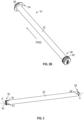
FIG. 3 is a perspective view of a sleeve that is part of the electrical pass-through assembly, according to an exemplary embodiment; -
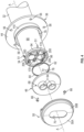
FIG. 4 is an exploded view of a fixed end of the sleeve, according to an exemplary embodiment; -
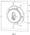
FIG. 5 is an illustration of the electrical pass-through assembly installed to a front spar of the aircraft wing shown inFIG. 1 , according to an exemplary embodiment; -
FIG. 6 is a perspective view of a fitting that is part of the electrical pass-through assembly, according to an exemplary embodiment; -
FIG. 7 is an enlarged view of the fixed end of the sleeve, according to an exemplary embodiment; -
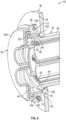
FIG. 8 is a cross-sectioned view of the fixed end of the sleeve, according to an exemplary embodiment; -
FIG. 9 is an exploded view of a locked end of the sleeve, according to an exemplary embodiment; -
FIG. 10 is an enlarged view of the locked end of the sleeve, according to an exemplary embodiment; -
FIG. 11 illustrates a locking retainer that is engaged with the locked end of the sleeve shown inFIG. 10 , according to an exemplary embodiment; -
FIG. 12 illustrates the electrical pass-through assembly when viewed from the locked end, where a second dust seal and a second dust cap have been removed, according to an exemplary embodiment; -
FIG. 13 illustrates two wiring harness sleeves before they are interlocked together, according to an exemplary embodiment; -
FIG. 14 illustrates the wiring harness sleeves after they are interlocked to one another, according to an exemplary embodiment; -
FIG. 15 illustrates two wiring harnesses being installed within the wiring harness sleeves, according to an exemplary embodiment; -
FIG. 16 illustrates a sleeve lock being installed to the wiring harness sleeves, according to an exemplary embodiment; -
FIG. 17 illustrates the sleeve lock after being installed to the wiring harness sleeves, according to an exemplary embodiment; -
FIG. 18 illustrates the wiring harness sleeves being inserted into the sleeve of the electrical pass-through assembly, according to an exemplary embodiment; -
FIG. 19 illustrates the electrical pass-through assembly when viewed from the locked end, according to an exemplary embodiment; -
FIG. 20 is a longitudinal cross-sectioned view of the sleeve, according to an exemplary embodiment; -
FIG. 21 is an enlarged view of the fixed end of the sleeve, according to an exemplary embodiment; -
FIG. 22 is an enlarged view of the locked end of the sleeve, according to an exemplary embodiment; and -
FIGS. 23A-23B illustrates a process flow diagram illustrating a method for installing the electrical pass-through assembly, according to an exemplary embodiment. - The present disclosure is directed towards an electrical pass-through assembly configured to extend lengthwise through the front spar and the rear spar of an aircraft wing. The electrical pass-through assembly includes a sleeve defining a fixed end, a locked end, a passage extending between the fixed end and the locked end, a mating feature disposed on the fixed end, and a locking feature disposed on the locked end. Both the fixed end and the locked end of the sleeve are sealed to prevent contaminants from entering the sleeve. The electrical pass-through assembly also includes a fitting that is attached to the wing. The fitting is attached to a front spar of the wing. The fitting includes a corresponding mating feature disposed along an inner surface of the fitting that engages with the mating feature disposed at the fixed end of the sleeve to prevent relative rotation between the fitting and the sleeve. The electrical pass-through assembly also includes a locking retainer including a corresponding locking feature that securely engages with the locking feature disposed at the locked end of the sleeve. The electrical pass-through assembly further includes one or more wiring harness sleeves that are secured within the sleeve. The wiring harnesses are secured so as to prevent rotation or translation within the sleeve.
- The following description is merely exemplary in nature and is not intended to limit the present disclosure, application, or uses.
- Referring to
FIG. 1 , an electrical pass-throughassembly 10 that traverses astructure 12 is illustrated. In the non-limiting embodiment as shown inFIG. 1 , thestructure 12 is represented by anaircraft wing 8.FIG. 1 illustrates a skeletal structure of theaircraft wing 8, which includes afront spar 16, arear spar 18, a plurality ofribs 14, and alower cover 22. The plurality ofribs 14 extend between thefront spar 16 and therear spar 18.FIG. 1 is viewed from anaft end 26 of theaircraft wing 8. In an example,aircraft wing 8 is a composite wing constructed of composite materials. In one embodiment, theaircraft wing 8 may be constructed of carbon fiber reinforced plastic (CFRP) materials. The electrical pass-throughassembly 10 extends lengthwise through respective openings (not visible inFIG. 1 ) in thefront spar 16 and therear spar 18 of theaircraft wing 8. The electrical pass-throughassembly 10 secures one or more wiring harnesses 30 within asleeve 32. In an example, the wiring harnesses 30 comprise power feeder wires, such as power feeder wires for equipment such as an actuator. It is to be appreciated that the electrical pass-throughassembly 10 may be located in areas of theaircraft wing 8 that may potentially comprise volatile liquid or gases (e.g., fuel vapor), such as an area outboard of a surge fuel tank (not shown) located within theaircraft wing 8. In an example, the area outboard of a surge fuel tank comprises a vapor leakage zone. As explained below, the electrical pass-throughassembly 10 protects the one or more wiring harnesses 30 from the environment within theaircraft wing 8. - Although
FIG. 1 illustrates thestructure 12 as an aircraft wing, it is to be appreciated that this illustration is merely exemplary in nature. Indeed, the electrical pass-throughassembly 10 may be used in a variety of other applications and is not limited to an aircraft wing. Specifically, in one embodiment, the electrical pass-throughassembly 10 may be used to pass high voltage wires through an enclosed space that may potentially comprise volatile liquid or gases (e.g., fuel vapor). One example is a confined area within a facility that produces volatile compounds, such as an oil refinery. -
FIG. 2A illustrates the electrical pass-throughassembly 10 when viewed from aforward end 28 of the aircraft wing 8 (FIG. 1 ) andFIG. 2B is an illustration of the electrical pass-throughassembly 10 viewed from theaft end 26 of the aircraft wing 8 (FIG. 1 ). Referring toFIGS. 1, 2A and2B thesleeve 32 defines afixed end 34 and a lockedend 38. The electrical pass-throughassembly 10 includes a fitting 36 and a lockingretainer 40. The fitting 36 is disposed at thefixed end 34 of thesleeve 32, and the lockingretainer 40 is securely engaged with the lockedend 38 of thesleeve 32. It is to be appreciated that both thefixed end 34 and the lockedend 38 of thesleeve 32 are sealed respectively by a first dust seal 46 (seen inFIG. 4 ) and a second dust seal 48 (seen inFIG. 9 ) and a first dust cap 50 (seen inFIG. 4 ) and a second dust cap 52 (seen inFIG. 9 ). -
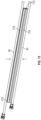
FIG. 3 is a perspective view of thesleeve 32. Thesleeve 32 further defines apassage 42 extending between thefixed end 34 and the lockedend 38, amating feature 51 disposed on thefixed end 34, and alocking feature 54 disposed on the lockedend 38. The one or more wiring harnesses 30 (seen inFIGS. 1 ,12 and15 ) are received within thepassage 42 of thesleeve 32 and extends along a longitudinal axis A-A of thesleeve 32 through both thefixed end 34 and the lockedend 38 of thesleeve 32. As seen inFIG. 1 , thesleeve 32 extends lengthwise through thefront spar 16 and therear spar 18 of theaircraft wing 8, therefore routing the wiring harnesses 30 through theaircraft wing 8. In the embodiment as shown inFIG. 3 , thesleeve 32 includes a tubular profile, however, it is to be appreciated that thesleeve 32 may include other geometries as well. -
FIG. 4 is an exploded view of the electrical pass-throughassembly 10 taken at thefixed end 34 of thesleeve 32 illustrating the fitting 36, afirst retaining ring 62, thefirst dust seal 46, thefirst dust cap 50, and a pair offasteners 66. Thefirst dust seal 46 is disposed at thefixed end 34 of thesleeve 32. The first retaining ring is constructed of anelongated member 60 that is not joined at its respective ends 72, thereby defining asplit 78. Thefirst retaining ring 62 is secured to thesleeve 32 by a plurality of first retaining features 200 (also seen inFIG. 20 ) that are part of thesleeve 32 and is described in greater detail below. - The
first dust seal 46 includes one ormore openings 64 that seal around the one or more wiring harnesses 30 (FIGS. 1 and12 ) and is split lengthwise along acenter portion 68 to seal around the one or more wiring harnesses 30. Thefirst dust seal 46 and the second dust seal 48 (seen inFIG. 9 ) substantially prevent debris from entering thesleeve 32, and are constructed of a flexible material such as, for example, rubber. Thefirst dust cap 50 fits over thefirst dust seal 46 and is split into twoseparate sections first dust cap 50 may be constructed of plastic and also prevents debris from entering thesleeve 32. As explained in greater detail and shown inFIG. 8 , thefasteners 66 are used to secure theseparate sections first dust cap 50 to one another. The twoseparate sections first dust cap 50 define anopening 70 for receiving the one or more wiring harnesses 30. -
FIG. 5 is an illustration of the electrical pass-throughassembly 10 viewed at thefront spar 16. The fitting 36 is configured to attach the structure 12 (FIG. 1 ). Specifically, in the embodiment as shown in the figures, the fitting 36 is rigidly attached to thefront spar 16 of theaircraft wing 8 by a plurality offasteners 58 that are received by openings 56 (seen inFIG. 4 ) disposed around aflange 44 of the fitting 36. Thus, thefixed end 34 of thesleeve 32 is attached to thefront spar 16 of theaircraft wing 8. In contrast, the lockedend 38 of thesleeve 32 is not rigidly attached to theaircraft wing 8, and therefore is not subjected to the loads caused by thermal expansion and contraction as well as vibrations that are experienced by theaircraft wing 8 during operation. It is to be appreciated that all of the components of the electrical pass-through assembly 10 (i.e., thesleeve 32, the fitting 36, the lockingretainer 40, the dust seals 46, 48, the dust caps 50, 52, the retaining rings 62, 124, and the wiring harness sleeves 170) except for the fasteners 66 (FIG. 4 ) and 126 (FIG. 9 ) used to secure the dust caps 50, 52 are constructed of nonconductive materials. As a result, attachment between the fitting 36 to thefront spar 16 does not require specialized grounding fasteners. -
FIG. 6 is a perspective view of the fitting 36 andFIG. 7 is an enlarged view of thefixed end 34 of thesleeve 32. Referring toFIGS. 6 and 7 , the fitting 36 includes aninner surface 74 defining anopening 76. Theopening 76 of the fitting 36 is shaped to receive thefixed end 34 of thesleeve 32. Acorresponding mating feature 80 is disposed along theinner surface 74 of the fitting 36 and engages with themating feature 51 disposed at thefixed end 34 of thesleeve 32 to prevent relative rotation between the fitting 36 and thesleeve 32. The fitting 36 is rigidly attached to the structure 12 (i.e., thefront spar 16 seen inFIG. 5 ), which in turn secures thefixed end 34 of thesleeve 32 to thestructure 12. As explained below, a lip 94 (FIG. 7 ) that circumferentially extends around theouter surface 90 of thesleeve 32 allows for thesleeve 32 to move relative to the fitting 36 to account for manufacturing tolerances during assembly. - In the non-limiting embodiment as shown in
FIGS. 6-7 , themating feature 51 disposed on thefixed end 34 of thesleeve 32 and thecorresponding mating feature 80 disposed along theinner surface 74 of the fitting 36 comprise one ormore interlocking tabs 84. Specifically, the one ormore interlocking tabs 84 include a plurality of raisedtabs 88 disposed along anouter surface 90 of thesleeve 32. In the embodiment as shown inFIG. 7 , thesleeve 32 comprises of four raisedtabs 88 disposed equidistant from one another. The one ormore interlocking tabs 84 further include a plurality of corresponding recessedtabs 92 disposed around theinner surface 74 of the fitting 36, where the corresponding recessedtabs 92 are shaped to engage with the raisedtabs 88 disposed around theouter surface 90 of thesleeve 32, thereby preventing relative rotation between thesleeve 32 and the fitting 36. It is to be appreciated that the one ormore interlocking tabs 84 shown inFIG. 6-7 are exemplary in nature, and any other type of feature for preventing relative rotation between thesleeve 32 and the fitting 36 may be used as well. - Referring specifically to
FIG. 7 , thefixed end 34 of thesleeve 32 includes thelip 94 that circumferentially extends around theouter surface 90 of thesleeve 32. Thelip 94 is disposed at anend 98 of thefixed end 34 of thesleeve 32.FIG. 8 is a cross-sectioned view of thefixed end 34 of thesleeve 32. Thelip 94 of thesleeve 32 engages with theinner surface 74 of the fitting 36. The interface between thelip 94 and theinner surface 74 of the fitting 36 allows thesleeve 32 to move relative to the rear spar 18 (FIG. 1 ) during assembly in order to account for manufacturing tolerances between thefront spar 16 and therear spar 18. In the exemplary embodiment as shown, thelip 94 of thesleeve 32 includes aspherical profile 100, however, it is to be appreciated that other geometries may be used as well. In the example as shown inFIG. 8 , the interface between thespherical profile 100 of thelip 94 and theinner surface 74 of the fitting 36 allows for manufacturing tolerance misalignment between thefront spar 16 and the rear spar 18 (FIG. 1 ). - Continuing to refer to
FIG. 8 , thefirst dust seal 46 is disposed at theend 98 of thefixed end 34 of thesleeve 32 and is engaged with afirst lip 102 disposed circumferentially around theopening 76 of the fitting 36. In other words, thefirst dust seal 46 fits over thefirst lip 102 disposed around theopening 76 of the fitting 36. The twoseparate sections section 50A is shown inFIG. 8 ) are installed over thefirst dust seal 46. Each of the twoseparate sections first dust cap 50 define acircumferential lip 108. Thecircumferential lip 108 is received by acircumferential groove 110 disposed around the fitting 36. Eachfastener 66 is received by acorresponding opening 112 within thesection 50A of thefirst dust cap 50 and secures thesection 50A with the opposingsection 50B (seen inFIG. 4 ) of thefirst dust cap 50. -
FIG. 9 is an exploded view of the lockedend 38 of thesleeve 32, where the electrical pass-throughassembly 10 includes a sealingwasher 120, a tensioningmember 122, asecond retaining ring 124, the lockingretainer 40, thesecond dust seal 48, and thesecond dust cap 52, and a pair offasteners 126. In the embodiment as shown inFIG. 9 , the lockedend 38 of thesleeve 32 is received by an opening (not visible) in therear spar 18. The sealingwasher 120 includes an opening (not visible) that is received by the lockedend 38 of thesleeve 32. The sealingwasher 120 is an anti-friction sealing washer that is disposed directly adjacent to anouter surface 130 of therear spar 18. The sealingwasher 120 acts as a physical barrier that protects theouter surface 130 of therear spar 18 from abrasions that may occur when the tensioningmember 122 vibrates during flight. The tensioningmember 122 defines anopening 134 that is received by the lockedend 38 of thesleeve 32 and is placed between the sealingwasher 120 and the lockingretainer 40. In the embodiment as shown inFIG. 9 , the tensioningmember 122 is a spring washer or a wave washer. - Similar to the
first retaining ring 62 seen inFIG. 4 , thesecond retaining ring 124 is constructed of anelongated member 128 that is not joined at its respective ends 132, thereby creating asplit 136. Thesecond retaining ring 124 is secured to thesleeve 32 by a plurality of second retaining features 202 that are part of thesleeve 32 and is described in greater detail below. Thesecond dust seal 48 is disposed on the lockingretainer 40 of thesleeve 32. Thesecond dust seal 48 includes one ormore openings 134 that seal around the one or more wiring harnesses 30 (FIG. 1 ) and is split lengthwise along acenter portion 138 to seal around the one or more wiring harnesses 30. Thesecond dust cap 52 fits over thesecond dust seal 48 and is split into twoseparate sections first dust cap 50, thesecond dust cap 52 is also constructed of plastic and prevents debris from entering thesleeve 32. The twoseparate sections second dust cap 52 define anopening 140 for receiving the one or more wiring harnesses 30. - The
second dust seal 48 is disposed at anend 144 of the lockingretainer 40 and is engaged with asecond lip 142 disposed circumferentially around anopening 146 defined by the lockingretainer 40. The twoseparate sections second dust cap 52 are installed over thesecond dust seal 48. Each of the twoseparate sections second dust cap 52 define acircumferential lip 148. Thecircumferential lip 148 is received by acircumferential groove 150 disposed around the lockingretainer 40. Eachfastener 126 is received by acorresponding opening 152 within thesections second dust cap 52 to secure thesections -
FIG. 10 is an enlarged view of the lockedend 38 of thesleeve 32 andFIG. 11 illustrates the lockingretainer 40. Referring toFIGS. 10 and 11 , the lockingretainer 40 is securely engaged with the lockedend 38 of thesleeve 32. Aninner surface 171 of the lockingretainer 40 defines theopening 146. Theopening 146 of the lockingretainer 40 is shaped to receive the lockedend 38 of thesleeve 32. The lockingretainer 40 includes acorresponding locking feature 160 disposed around theinner surface 171 of theopening 146 that securely engages with the lockingfeature 54 disposed at the lockedend 38 of thesleeve 32. - In the exemplary embodiment as shown in
FIG. 10 , the lockingfeature 54 disposed on the lockedend 38 of thesleeve 32 includes one or more rampedgrooves 164 that extend around theouter surface 90 of thesleeve 32 and terminate at acorresponding end stop 166. Referring toFIG. 11 , thecorresponding locking feature 160 of the lockingretainer 40 includes one or more raisedposts 168 disposed around theinner surface 171 of theopening 146, where each raisedpost 168 is configured to lockingly engage with a corresponding end stop 166 of one of the rampedgrooves 164. When the raisedposts 168 of the lockingretainer 40 are engaged with the corresponding end stops 166 disposed on thesleeve 32, the lockingretainer 40 is securely engaged with the lockedend 38 of thesleeve 32. The tensioning member 122 (seen inFIG. 9 ) is configured to provide tension between the lockingretainer 40 and thestructure 12. The tensioningmember 122 ensures the lockingretainer 40 stays engaged with the lockedend 38 of thesleeve 32 when the electrical pass-throughassembly 10 is exposed to vibration and thermal expansion. - In the non-limiting embodiment as shown in
FIGS. 10 and 11 , the lockedend 38 of thesleeve 32 includes four rampedgrooves 164 spaced equidistant from one another, and the lockingretainer 40 includes four corresponding raisedposts 168 spaced equidistant from one another. It is to be appreciated that the lockingfeature 54 disposed on thesleeve 32 shown inFIG. 10 and thecorresponding locking feature 160 disposed on the lockingretainer 40 shown inFIG. 11 are exemplary in nature, and any other type of feature for secure engagement between thesleeve 32 and the lockingretainer 40 may be used as well. -
FIG. 12 illustrates the electrical pass-throughassembly 10 when viewed from the lockedend 38, where thesecond dust seal 48 and the second dust cap 52 (FIG. 9 ) have been removed. The electrical pass-throughassembly 10 further includes one or more wiring harnesssleeves 170 that are contained inside thepassage 42 of thesleeve 32. Eachwiring harness sleeve 170 includes a passageway 172 (FIGS. 13 and 14 ) configured to contain acorresponding wiring harness 30. In the embodiment as shown inFIG. 12 , twowiring harness sleeves 170 are disposed within thesleeve 32, however, it is to be appreciated that fewer or more wiring harnesssleeves 170 may be included as part of the electrical pass-throughassembly 10 depending upon the application. - The two
wiring harness sleeves 170 are secured within thesleeve 32 of the electrical pass-throughassembly 10 and are interlocked with one another.FIG. 13 illustrates the twowiring harness sleeves 170 before they are interlocked together, andFIG. 14 illustrates thewiring harness sleeves 170 interlocked to one another during assembly. In the embodiment as shown inFIGS. 12 ,13, and 14 , the one or more wiring harnesssleeves 170 include of a pair of identicalwiring harness sleeves 170 that interlock with one another. Eachpassageway 172 of thewiring harness sleeves 170 includes arounded profile 174, an open top 176, and a pair of longitudinally extending hooks 178. Eachwiring harness sleeve 170 also includes a pair of longitudinally extendingtabs 180 disposed opposite to thepassageway 172. As seen inFIGS. 13 and 14 , one of thewiring harness sleeves 170 is translated in a longitudinal direction D such that thelongitudinally extending tabs 180 slidingly engage and interlock with thelongitudinally extending tabs 180 disposed on the remainingwiring harness sleeve 170. - Turning to
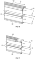
FIG. 15 , once thewiring harness sleeves 170 interlock with one another, a correspondingwiring harness 30 is placed within thepassageway 172 of each of the one or more wiring harnesssleeves 170. Referring toFIG. 16 and FIG. 17 , once the wiring harnesses 30 are placed within theirrespective passageways 172, asleeve lock 182 is slid in the longitudinal direction D over thepassageway 172 of each of the one or more wiring harnesssleeves 170. Thesleeve lock 182 is configured to retain thewiring harness 30 within therespective passageway 172 of thewiring harness sleeve 170. Referring toFIG. 18 , aconnector 184 is placed on eachend 186 of the wiring harnesses 30 (only one end is shown inFIG. 18 ), and the wiring harnesses 30 are then slid through thesleeve 32. -
FIG. 19 illustrates the electrical pass-throughassembly 10 when viewed from the lockedend 38 of thesleeve 32, where thesecond dust seal 48, thesecond dust cap 52, the second retaining ring 124 (FIG. 9 ), and the wiring harnesses 30 have been removed (thefirst retaining ring 62 disposed on thefixed end 34 of thesleeve 32 is still visible).FIG. 20 is a longitudinal cross-sectioned view of thesleeve 32, where aninner surface 190 of thesleeve 32. Referring toFIG. 20 , thesleeve 32 includes one or more pairs ofblades 192 that extend longitudinally along theinner surface 190 of thesleeve 32. Each pair ofblades 192 corresponds to one of thewiring harness sleeves 170. Thus, in the example as shown inFIGS. 19 and20 , thesleeve 32 includes two pairs of blades 192 (only one pair ofblades 192 is visible inFIG. 20 ). As seen inFIG. 19 , eachsleeve lock 182 is engaged between one of the pairs ofblades 192, where engagement of thesleeve lock 182 between the twoblades 192 prevents relative rotation between the respectivewiring harness sleeve 170 and thesleeve 32. Specifically, eachsleeve lock 182 includes a pair of longitudinally extendingcurved ribs 194 that are disposed between a corresponding pair ofblades 192 of thesleeve 32. Eachcurved rib 194 also defines alongitudinally extending channel 196 that is shaped to receive one of thelongitudinally extending hooks 178 of the correspondingwiring harness sleeves 170. - Referring specifically to
FIG. 20 , eachblade 192 of the one or more pairs ofblades 192 includes afirst retaining feature 200 disposed at thefixed end 34 of thesleeve 32. In the exemplary embodiment as shown, thefirst retaining feature 200 is arecess 210 shaped to receive a portion of theelongated member 60 of thefirst retaining ring 62. Likewise, as seen inFIG. 22 , eachblade 192 also includes asecond retaining feature 202 disposed at the lockedend 38 of thesleeve 32, where the retainingfeature 202 is arecess 212 shaped to receive a portion of theelongated member 128 of thesecond retaining ring 124. - Referring to
FIG. 21 , thefirst retaining ring 62 is secured by thefirst retaining feature 200 of each blade 192 (only two of theblades 192 are visible inFIG. 20 ). Thefirst retaining ring 62 abuts against afirst end surface 206 of the one or more wiring harnesssleeves 170 to prevent translational movement of the one or more wiring harnesssleeves 170 within thesleeve 32. Similarly, as seen inFIG. 22 , thesecond retaining ring 124 engages with thesecond retaining feature 202 of eachblade 192. Thesecond retaining ring 124 abuts against asecond end surface 208 of the one or more wiring harnesssleeves 170 to prevent translational movement of the one or more wiring harnesssleeves 170 within thesleeve 32. - In another aspect, a method of installing an electrical pass-through assembly 20 that traverses a
structure 12 is provided. - Within examples, the method of installing an electrical pass-through assembly 20 that traverses a
structure 12 includes attaching a fitting 36 to thestructure 12, wherein the fitting 36 includes aninner surface 74 defining anopening 76; inserting asleeve 32 within theopening 76 of the fitting 36, wherein thesleeve 32 includes afixed end 34, a lockedend 38, apassage 42 extending between thefixed end 34 and the lockedend 38, amating feature 51 disposed on thefixed end 34, and alocking feature 54 disposed on the lockedend 38; engaging themating feature 51 disposed on thefixed end 34 of thesleeve 32 with acorresponding mating feature 80 disposed along theinner surface 74 of the fitting 36 to prevent relative rotation between the fitting 36 and thesleeve 32; securely engaging the lockingfeature 54 disposed on the lockedend 38 of thesleeve 32 with acorresponding locking feature 160 that is part of a lockingretainer 40; and sliding one or more wiring harnesssleeves 170 through thesleeve 32, wherein the one or more wiring harnesssleeves 170 extend along a longitudinal axis of thesleeve 32 and extend through both thefixed end 34 and the lockedend 38. -
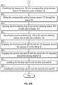
FIGS. 23A-23B illustrate a process flow diagram illustrating an exemplary method for installing the electrical pass-throughassembly 10 that traverses the structure 12 (shown inFIG. 1 ). Although the steps of the method are described as taking place according to a certain sequence, the described steps may also be performed in another order than the order described herein. It is further understood that certain steps may be performed concurrently, other steps added, or certain steps described herein omitted. Indeed, the descriptions of systems and processes in the present specification are provided for the purpose of illustrating certain embodiments and should in no way be interpreted to limit the subject matter disclosed. Referring now toFIGS. 1 ,5 , and23 ,method 300 begins atblock 302. Inblock 302, the fitting 36 is attached to thestructure 12. In the exemplary embodiment as shown in the figures, thestructure 12 is theaircraft wing 8, and the fitting 36 is attached to thefront spar 16 of theaircraft wing 8 by the plurality of fasteners 58 (seen inFIG. 5 ). Themethod 300 may then proceed to block 304. - Referring to
FIGS. 1 ,3 ,6 , and23 , inblock 304 thesleeve 32 is inserted through thestructure 12 and within theopening 76 of the fitting 36 (FIG. 6 ). In the embodiment as shown, thestructure 12 is theaircraft wing 8, and thesleeve 32 is received by openings (not visible in the figures) in thefront spar 16 and therear spar 18. Themethod 300 may then proceed to block 306. - Referring to
FIGS. 6, 7 , and23 , inblock 306 themating feature 51 disposed on thefixed end 34 of thesleeve 32 engages with acorresponding mating feature 80 disposed along theinner surface 74 of the fitting 36 to prevent relative rotation between the fitting 36 and thesleeve 32. Themethod 300 may then proceed to block 308. - Referring to
FIGS. 9 and23 , inblock 308 the lockedend 38 of thesleeve 32 is received by an opening (not visible inFIG. 9 ) of the sealingwasher 120. Themethod 300 may then proceed to block 310. - In
block 310, the lockedend 38 of thesleeve 32 is received by theopening 134 of the tensioningmember 122. Themethod 300 may then proceed to block 312. - Referring to
FIGS. 10, 11 , and23 , inblock 312 the lockingfeature 54 disposed on the lockedend 38 of thesleeve 32 securely engages with thecorresponding locking feature 160 of the lockingretainer 40. Themethod 300 may then proceed to block 314. - Referring to
FIGS. 13-14 and23 , inblock 314 the pair of identicalwiring harness sleeves 170 are interlocked with one another. Specifically, one of thewiring harness sleeves 170 is translated in the longitudinal direction D such that thelongitudinally extending tabs 180 slidingly engage and interlock with thelongitudinally extending tabs 180 disposed on the remainingwiring harness sleeve 170. Themethod 300 may then proceed to block 316. - Referring to
FIGS. 15 and23 , in block 316 awiring harness 30 is received within thepassageway 172 of each of the one or more wiring harnesssleeves 170. Themethod 300 may then proceed to block 318. - Referring to
FIGS. 16, 17 , and23 , inblock 318 thesleeve lock 182 is slid over thepassageway 172 of each of the one or more wiring harnesssleeves 170. Themethod 300 may then proceed to block 320. - Referring to
FIGS. 18 ,19 ,20 , and23 , inblock 320 thesleeve lock 182 of a correspondingwiring harness sleeve 170 is positioned between a pair ofblades 192 that extend longitudinally along aninner surface 190 of thesleeve 32. Themethod 300 may then proceed to block 322. - In
block 322, the correspondingwiring harness sleeve 170 is slid through thesleeve 32, where the one or more wiring harnesssleeves 170 extend along the longitudinal axis of thesleeve 32 and extend through both thefixed end 34 and the lockedend 38. Thesleeve lock 182 is engaged between the pair ofblades 192 to prevent relative rotation between thewiring harness sleeve 170 and thesleeve 32. Themethod 300 may then proceed to block 324. - Referring to
FIGS. 21 and23 , inblock 324 thefirst retaining ring 62 is secured by thefirst retaining feature 200 of each pair ofblades 192. Themethod 300 may then proceed to block 326. - Referring to
FIGS. 22 and23 , inblock 326 thesecond retaining ring 124 is secured by thesecond retaining feature 202 of each pair of blades. Themethod 300 may then proceed to block 328. - Referring to
FIGS. 4 ,8 , and23 , inblock 328 thefirst dust seal 46 engaged with thefirst lip 102 disposed around theopening 76 of the fitting 36. Themethod 300 may then proceed to block 330. - Referring to
FIGS. 9 and23 , inblock 330 thesecond dust seal 48 engages with thesecond lip 142 disposed around the lockingretainer 40. Themethod 300 may then proceed to block 332. - Referring to
FIGS. 4 ,8 , and23 , inblock 332 thefirst dust cap 50 is installed over thefirst dust seal 46, and the twoseparate sections fasteners 66. Themethod 300 may then proceed to block 334. - Referring to
FIGS. 9 and23 , inblock 334 thesecond dust cap 52 is installed over thesecond dust seal 48, and the twoseparate sections fasteners 126. Themethod 300 may then terminate. - Referring generally to the figures, the disclosed electrical pass-through assembly provides various technical effects and benefits. Specifically, the electrical pass-through assembly is capable of securing multiple wiring harness in place without using clamps. Moreover, the pass-through assembly either prevents or limits the wiring harnesses from rotating or translating during flight. Since disclosed electrical pass-through assembly includes a fixed end that is attached to the aircraft wing and a locked end that is not rigidly attached to the aircraft wing, the sleeve is not subjected to loads caused by the thermal expansion and contraction as well as vibrations. The disclosed electrical pass-through assembly also provides two layers of protection to the wiring harnesses, which are the sleeve and the wiring harness sleeves. The electrical-pass through assembly enables wiring to be installed in confined areas that can potentially comprise volatile liquid or gases (e.g., fuel vapor). For example, the disclosed electrical pass-through assembly may pass high voltage wires (e.g., power feeder wires) in the area outboard of a surge fuel tank located within an aircraft wing. Finally, it is to be appreciated that the pass-through assembly routes the wiring harnesses through the aircraft wing, between the front spar and the rear spar, and therefore allows for electrical power to be supplied to the outboard wing while maintaining separation on the inboard wing. The disclosed electrical pass-through assembly can therefore help to reduce or limit an amount of power feeder wires that are routed along the front or rear spar.
- The description of the present disclosure is merely exemplary in nature and variations that do not depart from the scope of the appended claims are intended to be within the scope of the invention.
Claims (15)
- An electrical pass-through assembly (10) configured to extend lengthwise through a front spar and a rear spar of an aircraft wing (12) comprising:a sleeve (32) defining a fixed end (34), a locked end (38), a passage (42) extending between the fixed end (34) and the locked end (38), a mating feature (51) disposed on the fixed end (34), and a locking feature (54) disposed on the locked end (38);a fitting (36) configured to attach to the wing (12), the fitting (36) including an inner surface (74) defining an opening (76) shaped to receive the fixed end (34) of the sleeve (32), wherein a corresponding mating feature (80) is disposed along the inner surface (74) of the fitting (36) and engages with the mating feature (51) disposed at the fixed end (34) of the sleeve (32) to prevent relative rotation between the fitting (36) and the sleeve (32); anda locking retainer (40) including a corresponding locking feature (160) that securely engages with the locking feature (54) disposed at the locked end (38) of the sleeve (32).
- The electrical pass-through assembly (10) of claim 1, further comprising a tensioning member (122) received by the locked end (38) of the sleeve (32), wherein the tensioning member (122) is configured to provide tension between the locking retainer (40) and the structure (12).
- The electrical pass-through assembly (10) of claim 1 or 2, further comprising one or more wiring harnesses (30) received within the passage (42) of the sleeve (32), wherein the one or more wiring harnesses (30) extend along a longitudinal axis of the sleeve (32) through both the fixed end (34) and the locked end (38).
- The electrical pass-through assembly (10) of claim 3, further comprising one or more wiring harness sleeves (170), wherein each wiring harness sleeve includes a passageway (172) configured to contain a corresponding wiring harness (30).
- The electrical pass-through assembly (10) of any of claims 1-4, wherein the mating feature (51) disposed on the fixed end (34) of the sleeve (32) and the corresponding mating feature (80) disposed along the inner surface (74) of the fitting (36) comprise one or more interlocking tabs (84).
- The electrical pass-through assembly (10) of any of claims 1-5, wherein the fixed end (34) of the sleeve (32) includes a lip (94) that circumferentially extends around an outer surface (90) of the sleeve (32), wherein the lip (94) of the sleeve (32) engages with the inner surface (74) of the fitting (36).
- The electrical pass-through assembly (10) of any of claims 1-6, wherein the locking feature (54) disposed on the locked end (38) of the sleeve (32) includes one or more ramped grooves (164) that extend around an outer surface (90) of the sleeve (32) and terminate at an end stop (166).
- The electrical pass-through assembly (10) of any of claims 1-7, further comprising a first dust seal (46) disposed on the fixed end (34) of the sleeve (32), wherein the first dust seal (46) is split to seal around one or more wiring harnesses (30).
- The electrical pass-through assembly (10) of any of claims 1-8, further comprising a second dust seal (48) disposed on the locked end (38) of the sleeve (32), wherein the second dust seal (48) is split to seal around one or more wiring harnesses (30).
- An aircraft comprising an electrical pass-through assembly according to any of the preceding claims.
- A method (300) of installing an electrical pass-through assembly (10) that extends lengthwise through a front spar and a rear spar of an aircraft wing (12) the method (300) comprising:attaching a fitting (36) to the wing (12), wherein the fitting (36) includes an inner surface (74) defining an opening (76);inserting a sleeve (32) within the opening (76) of the fitting (36), wherein the sleeve (32) includes a fixed end (34), a locked end (38), a passage (42) extending between the fixed end (34) and the locked end (38), a mating feature (51) disposed on the fixed end (34), and a locking feature (54) disposed on the locked end (38);engaging the mating feature (51) disposed on the fixed end (34) of the sleeve (32) with a corresponding mating feature (80) disposed along the inner surface (74) of the fitting (36) to prevent relative rotation between the fitting (36) and the sleeve (32);securely engaging the locking feature (54) disposed on the locked end (38) of the sleeve (32) with a corresponding locking feature (160) that is part of a locking retainer (40); andsliding one or more wiring harness sleeves (170) through the sleeve (32), wherein the one or more wiring harness sleeves (170) extend along a longitudinal axis of the sleeve (32) and extend through both the fixed end (34) and the locked end (38).
- The method (300) of claim 11, wherein the one or more wiring harness sleeves (170) include a pair of identical wiring harness sleeves (170), and wherein the method (300) further comprises:
interlocking the pair of identical wiring harness sleeves (170) with one another. - The method (300) of claim 11 or 12, further comprising:receiving a wiring harness (30) within a passageway (172) of each of the one or more wiring harness sleeves (170); andsliding a sleeve lock (182) over the passageway (172) of each of the one or more wiring harness sleeves (170).
- The method (300) of claim 13, further comprising:positioning the sleeve lock (182) of a corresponding wiring harness sleeve (170) between a pair of blades (192) that extend longitudinally along an inner surface of the sleeve (32); andsliding the corresponding wiring harness sleeve (170) through the sleeve (32), wherein the sleeve lock (182) is engaged between the pair of blades (192) to prevent relative rotation between the wiring harness sleeve (170) and the sleeve (32).
- The method (300) of any of claims 11-14, further comprising:engaging a first dust seal (46) with a first lip (102) disposed around the opening (76) of the fitting (36); andengaging a second dust seal (48) with a second lip (142) disposed around the locking feature (54).
Applications Claiming Priority (1)
| Application Number | Priority Date | Filing Date | Title |
|---|---|---|---|
| US202163162157P | 2021-03-17 | 2021-03-17 |
Publications (2)
| Publication Number | Publication Date |
|---|---|
| EP4059834A1 EP4059834A1 (en) | 2022-09-21 |
| EP4059834B1 true EP4059834B1 (en) | 2025-05-07 |
Family
ID=80738633
Family Applications (1)
| Application Number | Title | Priority Date | Filing Date |
|---|---|---|---|
| EP22161762.4A Active EP4059834B1 (en) | 2021-03-17 | 2022-03-14 | Electrical pass-through assembly for traversing a structure |
Country Status (3)
| Country | Link |
|---|---|
| US (1) | US12117115B2 (en) |
| EP (1) | EP4059834B1 (en) |
| JP (1) | JP2022145626A (en) |
Families Citing this family (3)
| Publication number | Priority date | Publication date | Assignee | Title |
|---|---|---|---|---|
| DE102022116949A1 (en) * | 2022-07-07 | 2024-01-18 | Airbus Operations Gmbh | Wing for an aircraft |
| CN117712752A (en) * | 2022-09-13 | 2024-03-15 | 李尔公司 | Cap assembly for electrical pathway |
| US12176697B2 (en) * | 2023-03-24 | 2024-12-24 | Archer Aviation Inc. | Systems and methods for routing electrical wiring through an aircraft structure |
Family Cites Families (12)
| Publication number | Priority date | Publication date | Assignee | Title |
|---|---|---|---|---|
| US2913260A (en) * | 1952-11-26 | 1959-11-17 | Glenn G Givens | Cable stuffing tubes |
| GB9406362D0 (en) * | 1994-03-30 | 1994-05-25 | Davidson Paul | Pipe muff system |
| JP2003023718A (en) * | 2001-07-05 | 2003-01-24 | Sumitomo Wiring Syst Ltd | Grommet |
| JP4657192B2 (en) * | 2006-11-08 | 2011-03-23 | 本田技研工業株式会社 | Aircraft main wing structure |
| US8003889B2 (en) * | 2007-08-02 | 2011-08-23 | Thomas & Betts International, Inc. | Conduit sleeve pass through for concrete construction |
| TWI430530B (en) * | 2010-08-02 | 2014-03-11 | A cable - like flexible circuit cable with a waterproof section | |
| CN104620329B (en) * | 2012-10-31 | 2017-03-15 | 德尔福技术有限公司 | Apparatus and method for montage shielded cable |
| US9543747B2 (en) * | 2013-10-30 | 2017-01-10 | Delphi Technologies, Inc. | Method for splicing shielded wire cables |
| ES2800182T3 (en) * | 2017-07-13 | 2020-12-28 | Airbus Operations Sl | Structural arrangement of the box for an aircraft and its manufacturing process |
| FR3085089B1 (en) * | 2018-08-20 | 2022-02-25 | Latelec | ASSEMBLY FOR THE PROTECTION AND SECURING OF A WIRING HARNESS |
| US11434014B2 (en) * | 2018-10-10 | 2022-09-06 | Imagine Aero Inc. | Aircraft spars with integrated power cells, and associated systems and methods |
| US11038334B2 (en) * | 2019-01-14 | 2021-06-15 | The Boeing Company | Aircraft wing composite ribs having electrical grounding paths |
-
2022
- 2022-03-14 EP EP22161762.4A patent/EP4059834B1/en active Active
- 2022-03-15 US US17/695,156 patent/US12117115B2/en active Active
- 2022-03-15 JP JP2022040808A patent/JP2022145626A/en active Pending
Also Published As
| Publication number | Publication date |
|---|---|
| EP4059834A1 (en) | 2022-09-21 |
| US20220297850A1 (en) | 2022-09-22 |
| US12117115B2 (en) | 2024-10-15 |
| JP2022145626A (en) | 2022-10-04 |
Similar Documents
| Publication | Publication Date | Title |
|---|---|---|
| EP4059834A1 (en) | Electrical pass-through assembly for traversing a structure | |
| RU2754235C2 (en) | Clamping system for transport elements, method for stabilizing transport element and aircraft | |
| EP2887476B1 (en) | Wire harness exterior member and wire harness | |
| US9598028B2 (en) | Raceway for fastening, guiding and/or protecting electric cable means | |
| EP1826120B1 (en) | Method and system for electrical bonding of fuel tank penetrations | |
| US11381063B2 (en) | Assembly for protecting and securing a wiring harness | |
| EP2768730B1 (en) | Electrostatic discharge protected structure pass-thru | |
| US20150000974A1 (en) | Routing structure of wire harness and method for forming said routing structure | |
| KR102578187B1 (en) | Charging connector for vehicle | |
| EP3611097B1 (en) | Electrical isolator fitting | |
| CN106025660B (en) | The fixed structure of harness guard member | |
| US11005243B2 (en) | Aircraft cable routing system and method of installation thereof | |
| EP3156321B1 (en) | Composite stiffener with integral conductive element | |
| US10992201B2 (en) | Electrical propulsion system with corona suppression on a vehicle | |
| US20240304358A1 (en) | First wire harness and compound wire harness | |
| US11214206B2 (en) | Protective tube with fixing members, and wire harness | |
| CN111619470A (en) | Grommet and wire harness | |
| US9821733B2 (en) | Wire harness | |
| US12240388B2 (en) | Compound wire harness | |
| US20250141143A1 (en) | Device for electrically joining two sections of electrical cable, method for connecting two sections of electrical cable by way of such a device, and power cable equipped with such a device | |
| US20210242619A1 (en) | Interposer/electrical connector | |
| EP3686412B1 (en) | System of harness and engine case for aircraft engine | |
| JP7803785B2 (en) | Wire harness | |
| JP7755530B2 (en) | Grommet assembly and wiring harness | |
| CA3054217A1 (en) | Electrical isolator fitting |
Legal Events
| Date | Code | Title | Description |
|---|---|---|---|
| PUAI | Public reference made under article 153(3) epc to a published international application that has entered the european phase |
Free format text: ORIGINAL CODE: 0009012 |
|
| STAA | Information on the status of an ep patent application or granted ep patent |
Free format text: STATUS: THE APPLICATION HAS BEEN PUBLISHED |
|
| AK | Designated contracting states |
Kind code of ref document: A1 Designated state(s): AL AT BE BG CH CY CZ DE DK EE ES FI FR GB GR HR HU IE IS IT LI LT LU LV MC MK MT NL NO PL PT RO RS SE SI SK SM TR |
|
| RAP3 | Party data changed (applicant data changed or rights of an application transferred) |
Owner name: THE BOEING COMPANY |
|
| STAA | Information on the status of an ep patent application or granted ep patent |
Free format text: STATUS: REQUEST FOR EXAMINATION WAS MADE |
|
| 17P | Request for examination filed |
Effective date: 20230318 |
|
| RBV | Designated contracting states (corrected) |
Designated state(s): AL AT BE BG CH CY CZ DE DK EE ES FI FR GB GR HR HU IE IS IT LI LT LU LV MC MK MT NL NO PL PT RO RS SE SI SK SM TR |
|
| GRAP | Despatch of communication of intention to grant a patent |
Free format text: ORIGINAL CODE: EPIDOSNIGR1 |
|
| STAA | Information on the status of an ep patent application or granted ep patent |
Free format text: STATUS: GRANT OF PATENT IS INTENDED |
|
| RIC1 | Information provided on ipc code assigned before grant |
Ipc: H02G 3/04 20060101ALI20240913BHEP Ipc: B64C 3/18 20060101AFI20240913BHEP |
|
| INTG | Intention to grant announced |
Effective date: 20241022 |
|
| GRAS | Grant fee paid |
Free format text: ORIGINAL CODE: EPIDOSNIGR3 |
|
| GRAA | (expected) grant |
Free format text: ORIGINAL CODE: 0009210 |
|
| STAA | Information on the status of an ep patent application or granted ep patent |
Free format text: STATUS: THE PATENT HAS BEEN GRANTED |
|
| AK | Designated contracting states |
Kind code of ref document: B1 Designated state(s): AL AT BE BG CH CY CZ DE DK EE ES FI FR GB GR HR HU IE IS IT LI LT LU LV MC MK MT NL NO PL PT RO RS SE SI SK SM TR |
|
| REG | Reference to a national code |
Ref country code: GB Ref legal event code: FG4D |
|
| REG | Reference to a national code |
Ref country code: CH Ref legal event code: EP |
|
| REG | Reference to a national code |
Ref country code: DE Ref legal event code: R096 Ref document number: 602022014089 Country of ref document: DE |
|
| REG | Reference to a national code |
Ref country code: IE Ref legal event code: FG4D |
|
| REG | Reference to a national code |
Ref country code: NL Ref legal event code: MP Effective date: 20250507 |
|
| PG25 | Lapsed in a contracting state [announced via postgrant information from national office to epo] |
Ref country code: FI Free format text: LAPSE BECAUSE OF FAILURE TO SUBMIT A TRANSLATION OF THE DESCRIPTION OR TO PAY THE FEE WITHIN THE PRESCRIBED TIME-LIMIT Effective date: 20250507 Ref country code: PT Free format text: LAPSE BECAUSE OF FAILURE TO SUBMIT A TRANSLATION OF THE DESCRIPTION OR TO PAY THE FEE WITHIN THE PRESCRIBED TIME-LIMIT Effective date: 20250908 Ref country code: ES Free format text: LAPSE BECAUSE OF FAILURE TO SUBMIT A TRANSLATION OF THE DESCRIPTION OR TO PAY THE FEE WITHIN THE PRESCRIBED TIME-LIMIT Effective date: 20250507 |
|
| REG | Reference to a national code |
Ref country code: LT Ref legal event code: MG9D |
|
| PG25 | Lapsed in a contracting state [announced via postgrant information from national office to epo] |
Ref country code: GR Free format text: LAPSE BECAUSE OF FAILURE TO SUBMIT A TRANSLATION OF THE DESCRIPTION OR TO PAY THE FEE WITHIN THE PRESCRIBED TIME-LIMIT Effective date: 20250808 Ref country code: NO Free format text: LAPSE BECAUSE OF FAILURE TO SUBMIT A TRANSLATION OF THE DESCRIPTION OR TO PAY THE FEE WITHIN THE PRESCRIBED TIME-LIMIT Effective date: 20250807 |
|
| PG25 | Lapsed in a contracting state [announced via postgrant information from national office to epo] |
Ref country code: PL Free format text: LAPSE BECAUSE OF FAILURE TO SUBMIT A TRANSLATION OF THE DESCRIPTION OR TO PAY THE FEE WITHIN THE PRESCRIBED TIME-LIMIT Effective date: 20250507 Ref country code: NL Free format text: LAPSE BECAUSE OF FAILURE TO SUBMIT A TRANSLATION OF THE DESCRIPTION OR TO PAY THE FEE WITHIN THE PRESCRIBED TIME-LIMIT Effective date: 20250507 |
|
| REG | Reference to a national code |
Ref country code: AT Ref legal event code: MK05 Ref document number: 1792230 Country of ref document: AT Kind code of ref document: T Effective date: 20250507 |
|
| PG25 | Lapsed in a contracting state [announced via postgrant information from national office to epo] |
Ref country code: BG Free format text: LAPSE BECAUSE OF FAILURE TO SUBMIT A TRANSLATION OF THE DESCRIPTION OR TO PAY THE FEE WITHIN THE PRESCRIBED TIME-LIMIT Effective date: 20250507 |
|
| PG25 | Lapsed in a contracting state [announced via postgrant information from national office to epo] |
Ref country code: HR Free format text: LAPSE BECAUSE OF FAILURE TO SUBMIT A TRANSLATION OF THE DESCRIPTION OR TO PAY THE FEE WITHIN THE PRESCRIBED TIME-LIMIT Effective date: 20250507 |
|
| PG25 | Lapsed in a contracting state [announced via postgrant information from national office to epo] |
Ref country code: AT Free format text: LAPSE BECAUSE OF FAILURE TO SUBMIT A TRANSLATION OF THE DESCRIPTION OR TO PAY THE FEE WITHIN THE PRESCRIBED TIME-LIMIT Effective date: 20250507 |
|
| PG25 | Lapsed in a contracting state [announced via postgrant information from national office to epo] |
Ref country code: RS Free format text: LAPSE BECAUSE OF FAILURE TO SUBMIT A TRANSLATION OF THE DESCRIPTION OR TO PAY THE FEE WITHIN THE PRESCRIBED TIME-LIMIT Effective date: 20250807 |
|
| PG25 | Lapsed in a contracting state [announced via postgrant information from national office to epo] |
Ref country code: IS Free format text: LAPSE BECAUSE OF FAILURE TO SUBMIT A TRANSLATION OF THE DESCRIPTION OR TO PAY THE FEE WITHIN THE PRESCRIBED TIME-LIMIT Effective date: 20250907 |
|
| PG25 | Lapsed in a contracting state [announced via postgrant information from national office to epo] |
Ref country code: LV Free format text: LAPSE BECAUSE OF FAILURE TO SUBMIT A TRANSLATION OF THE DESCRIPTION OR TO PAY THE FEE WITHIN THE PRESCRIBED TIME-LIMIT Effective date: 20250507 |
|
| PG25 | Lapsed in a contracting state [announced via postgrant information from national office to epo] |
Ref country code: DK Free format text: LAPSE BECAUSE OF FAILURE TO SUBMIT A TRANSLATION OF THE DESCRIPTION OR TO PAY THE FEE WITHIN THE PRESCRIBED TIME-LIMIT Effective date: 20250507 Ref country code: SM Free format text: LAPSE BECAUSE OF FAILURE TO SUBMIT A TRANSLATION OF THE DESCRIPTION OR TO PAY THE FEE WITHIN THE PRESCRIBED TIME-LIMIT Effective date: 20250507 |
|
| PG25 | Lapsed in a contracting state [announced via postgrant information from national office to epo] |
Ref country code: CZ Free format text: LAPSE BECAUSE OF FAILURE TO SUBMIT A TRANSLATION OF THE DESCRIPTION OR TO PAY THE FEE WITHIN THE PRESCRIBED TIME-LIMIT Effective date: 20250507 |
|
| PG25 | Lapsed in a contracting state [announced via postgrant information from national office to epo] |
Ref country code: EE Free format text: LAPSE BECAUSE OF FAILURE TO SUBMIT A TRANSLATION OF THE DESCRIPTION OR TO PAY THE FEE WITHIN THE PRESCRIBED TIME-LIMIT Effective date: 20250507 |
|
| PG25 | Lapsed in a contracting state [announced via postgrant information from national office to epo] |
Ref country code: SK Free format text: LAPSE BECAUSE OF FAILURE TO SUBMIT A TRANSLATION OF THE DESCRIPTION OR TO PAY THE FEE WITHIN THE PRESCRIBED TIME-LIMIT Effective date: 20250507 |
|
| PG25 | Lapsed in a contracting state [announced via postgrant information from national office to epo] |
Ref country code: IT Free format text: LAPSE BECAUSE OF FAILURE TO SUBMIT A TRANSLATION OF THE DESCRIPTION OR TO PAY THE FEE WITHIN THE PRESCRIBED TIME-LIMIT Effective date: 20250507 |
|
| REG | Reference to a national code |
Ref country code: DE Ref legal event code: R097 Ref document number: 602022014089 Country of ref document: DE |
|
| PLBE | No opposition filed within time limit |
Free format text: ORIGINAL CODE: 0009261 |
|
| STAA | Information on the status of an ep patent application or granted ep patent |
Free format text: STATUS: NO OPPOSITION FILED WITHIN TIME LIMIT |
|
| REG | Reference to a national code |
Ref country code: CH Ref legal event code: L10 Free format text: ST27 STATUS EVENT CODE: U-0-0-L10-L00 (AS PROVIDED BY THE NATIONAL OFFICE) Effective date: 20260318 |
|
| PGFP | Annual fee paid to national office [announced via postgrant information from national office to epo] |
Ref country code: GB Payment date: 20260327 Year of fee payment: 5 |
|
| PGFP | Annual fee paid to national office [announced via postgrant information from national office to epo] |
Ref country code: DE Payment date: 20260327 Year of fee payment: 5 |
|
| 26N | No opposition filed |
Effective date: 20260210 |
|
| PGFP | Annual fee paid to national office [announced via postgrant information from national office to epo] |
Ref country code: FR Payment date: 20260325 Year of fee payment: 5 |