EP4059794A1 - Straddled vehicle with rear radar - Google Patents
Straddled vehicle with rear radar Download PDFInfo
- Publication number
- EP4059794A1 EP4059794A1 EP22162971.0A EP22162971A EP4059794A1 EP 4059794 A1 EP4059794 A1 EP 4059794A1 EP 22162971 A EP22162971 A EP 22162971A EP 4059794 A1 EP4059794 A1 EP 4059794A1
- Authority
- EP
- European Patent Office
- Prior art keywords
- radar
- seat frame
- vehicle
- tail light
- relative
- Prior art date
- Legal status (The legal status is an assumption and is not a legal conclusion. Google has not performed a legal analysis and makes no representation as to the accuracy of the status listed.)
- Granted
Links
Images




Classifications
-
- B—PERFORMING OPERATIONS; TRANSPORTING
- B62—LAND VEHICLES FOR TRAVELLING OTHERWISE THAN ON RAILS
- B62J—CYCLE SADDLES OR SEATS; AUXILIARY DEVICES OR ACCESSORIES SPECIALLY ADAPTED TO CYCLES AND NOT OTHERWISE PROVIDED FOR, e.g. ARTICLE CARRIERS OR CYCLE PROTECTORS
- B62J45/00—Electrical equipment arrangements specially adapted for use as accessories on cycles, not otherwise provided for
- B62J45/40—Sensor arrangements; Mounting thereof
- B62J45/41—Sensor arrangements; Mounting thereof characterised by the type of sensor
-
- B—PERFORMING OPERATIONS; TRANSPORTING
- B62—LAND VEHICLES FOR TRAVELLING OTHERWISE THAN ON RAILS
- B62J—CYCLE SADDLES OR SEATS; AUXILIARY DEVICES OR ACCESSORIES SPECIALLY ADAPTED TO CYCLES AND NOT OTHERWISE PROVIDED FOR, e.g. ARTICLE CARRIERS OR CYCLE PROTECTORS
- B62J1/00—Saddles or other seats for cycles; Arrangement thereof; Component parts
- B62J1/08—Frames for saddles; Connections between saddle frames and seat pillars; Seat pillars
-
- B—PERFORMING OPERATIONS; TRANSPORTING
- B62—LAND VEHICLES FOR TRAVELLING OTHERWISE THAN ON RAILS
- B62J—CYCLE SADDLES OR SEATS; AUXILIARY DEVICES OR ACCESSORIES SPECIALLY ADAPTED TO CYCLES AND NOT OTHERWISE PROVIDED FOR, e.g. ARTICLE CARRIERS OR CYCLE PROTECTORS
- B62J23/00—Other protectors specially adapted for cycles
-
- B—PERFORMING OPERATIONS; TRANSPORTING
- B62—LAND VEHICLES FOR TRAVELLING OTHERWISE THAN ON RAILS
- B62J—CYCLE SADDLES OR SEATS; AUXILIARY DEVICES OR ACCESSORIES SPECIALLY ADAPTED TO CYCLES AND NOT OTHERWISE PROVIDED FOR, e.g. ARTICLE CARRIERS OR CYCLE PROTECTORS
- B62J27/00—Safety equipment
-
- B—PERFORMING OPERATIONS; TRANSPORTING
- B62—LAND VEHICLES FOR TRAVELLING OTHERWISE THAN ON RAILS
- B62J—CYCLE SADDLES OR SEATS; AUXILIARY DEVICES OR ACCESSORIES SPECIALLY ADAPTED TO CYCLES AND NOT OTHERWISE PROVIDED FOR, e.g. ARTICLE CARRIERS OR CYCLE PROTECTORS
- B62J45/00—Electrical equipment arrangements specially adapted for use as accessories on cycles, not otherwise provided for
- B62J45/40—Sensor arrangements; Mounting thereof
- B62J45/42—Sensor arrangements; Mounting thereof characterised by mounting
-
- B—PERFORMING OPERATIONS; TRANSPORTING
- B62—LAND VEHICLES FOR TRAVELLING OTHERWISE THAN ON RAILS
- B62J—CYCLE SADDLES OR SEATS; AUXILIARY DEVICES OR ACCESSORIES SPECIALLY ADAPTED TO CYCLES AND NOT OTHERWISE PROVIDED FOR, e.g. ARTICLE CARRIERS OR CYCLE PROTECTORS
- B62J45/00—Electrical equipment arrangements specially adapted for use as accessories on cycles, not otherwise provided for
- B62J45/40—Sensor arrangements; Mounting thereof
- B62J45/42—Sensor arrangements; Mounting thereof characterised by mounting
- B62J45/423—Sensor arrangements; Mounting thereof characterised by mounting on or besides the wheel
-
- B—PERFORMING OPERATIONS; TRANSPORTING
- B62—LAND VEHICLES FOR TRAVELLING OTHERWISE THAN ON RAILS
- B62J—CYCLE SADDLES OR SEATS; AUXILIARY DEVICES OR ACCESSORIES SPECIALLY ADAPTED TO CYCLES AND NOT OTHERWISE PROVIDED FOR, e.g. ARTICLE CARRIERS OR CYCLE PROTECTORS
- B62J6/00—Arrangement of optical signalling or lighting devices on cycles; Mounting or supporting thereof; Circuits therefor
- B62J6/04—Rear lights
Definitions
- the present invention relates to a straddled vehicle having a radar on a rear portion of the vehicle body.
- Straddled vehicles having a radar on a rear portion of the vehicle body have been known in the art. Such straddled vehicles, with the radar, can detect other vehicles coming close from behind.
- the radar includes a transmitter that transmits radio waves, a receiver that receives radio waves (reflected waves) that have been reflected off objects such as other vehicles, an antenna, and a casing that houses these components.
- a radar The higher the performance of a radar, the larger the volume of the casing and the weight of the radar tend to be.
- a tail light and a rear fender are arranged on a rear portion of a straddled vehicle, and the space for installment of a radar is limited.
- a radar needs to be arranged so as not to block emitted light from the tail light. It is not easy to arrange a large casing on a rear portion of a straddled vehicle.
- the transmitter and the receiver of a radar may be housed in separate casings, thereby reducing the volume per casing.
- the transmitter and the receiver are housed in separate casings, it will be more difficult to route wires that connect them together.
- FIG. 2 of JP 2017-218133 A describes a motorcycle that includes, not a radar, but a detector that detects millimeter waves, etc., emitted from other vehicles.
- the detector is housed in a casing, and is provided on a rear portion of the vehicle body.
- the casing is attached to a rear fender downward of the tail light so as not to block emitted light from the tail light.
- JP 2017-218133 A also describes attaching the casing to a seat cowl.
- a straddled vehicle vibrates when, for example, running on an uneven road surface.
- a rear fender is made light in weight in order to reduce the weight of the vehicle body.
- the rigidity of a rear fender is relatively low. Therefore, if a large and heavy radar is attached to a rear fender, the radar is likely to be influenced by vibration as the rear fender bends due to vibration while running. In view of this, the rigidity of the rear fender may be increased so that the radar is less likely to be influenced by vibration. However, an attempt to increase the rigidity of the rear fender will increase the size and the weight of the rear fender.
- the radar may be arranged upward of the tail light by being attached to the seat cowl.
- the radar By arranging the radar upward of the tail light, it is possible to prevent the radar from blocking emitted light from the tail light.
- the seat cowl is a member whose rigidity is relatively low. Also when the radar is attached to the seat cowl, similar problems to those described above will occur. If a large radar is arranged upward of the tail light, the passenger's comfort may lower. Some straddled vehicle users prefer to attach a luggage box as an optional accessory upward of the tail light. However, such a luggage box cannot be attached if a large radar is arranged upward of the tail light.
- a straddled vehicle disclosed herein includes: a seat frame extending rearward and upward; a seat supported on the seat frame; a rear fender extending rearward and downward, the rear fender having a front end located forward relative to a rear end of the seat frame; a tail light having a rear end located rearward relative to a rear end of the seat; and a radar.
- the radar includes a transmitter that transmits radio waves, a receiver that receives radio waves, and a casing that houses the transmitter and the receiver.
- the radar is supported on the seat frame. At least a portion of the radar is arranged forward relative to a rear end of the tail light, downward relative to an upper end of the seat frame, rearward relative to a front end of the rear fender and upward relative to a lower end of the rear fender.
- the radar is arranged forward relative to the rear end of the tail light, downward relative to the upper end of the seat frame, rearward relative to the front end of the rear fender and upward relative to the lower end of the rear fender. Therefore, even a relatively large radar can be arranged in a rear portion of the vehicle body without difficulty.
- the radar is less likely to block emitted light from the tail light.
- the radar is supported on the seat frame. As compared with a case where the radar is supported on the rear fender or the seat cowl, the radar is less likely to be influenced by vibration. Therefore, it is possible to provide a straddled vehicle in which a radar does not block emitted light from the tail light and is less likely to be influenced by vibration.
- the straddled vehicle may include a seat cowl arranged sideward of the seat frame. It is preferred that the radar is not supported either one of the rear fender and the seat cowl.
- the seat frame includes a left seat frame and a right seat frame arranged rightward of the left seat frame.
- the straddled vehicle includes: a base member fixed to the left seat frame and the right seat frame; and a support member fixed to the base member. The radar is supported on the support member.
- the seat frame includes a left seat frame and a right seat frame arranged rightward of the left seat frame.
- the straddled vehicle includes a support member fixed to the left seat frame and the right seat frame.
- the radar is supported on the support member.
- the support member extends rearward and downward.
- the support member and the radar can be arranged in a compact arrangement.
- the straddled vehicle includes a rubber-made member interposed between the seat frame and the radar.
- vibration of the seat frame is less likely to be transmitted to the radar, and it is therefore possible to suppress vibration of the radar.
- the tail light is arranged upward relative to an upper end of the rear fender.
- the radar is arranged downward relative to a lower end of the tail light.
- the radar is arranged in a compact arrangement without blocking emitted light from the tail light.
- a direction of extension of a rear end portion of the seat frame is defined as a first direction and a direction perpendicular to the first direction is defined as a second direction, wherein a dimension of the tail light in the second direction is smaller than a dimension of the tail light in the first direction.
- the tail light is a thin-type tail light.
- the radar is arranged in a compact arrangement without blocking emitted light from the tail light.
- the tail light is attached to the rear fender.
- the radar is arranged upward relative to an upper end of the tail light.
- the radar is arranged in a compact arrangement without blocking emitted light from the tail light.
- a front end of the radar may be located forward relative to a rear end of the seat frame.
- a rear end of the radar may be located rearward relative to a rear end of the seat frame.
- a front end of the radar may be located forward relative to a front end of the tail light.
- a rear end of the radar may be located forward relative to a rear end of the tail light.
- a dimension of the casing in a front-rear direction may be smaller than a dimension the casing in an up-down direction.
- a straddled vehicle in which a radar provided on a rear portion of the vehicle body does not block emitted light from the tail light and is less likely to be influenced by vibration.
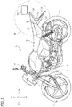
- FIG. 1 is a side view showing a motorcycle 1 according to one embodiment.
- the motorcycle 1 includes a front wheel 2, a rear wheel 3, a vehicle body 4 supported on the front wheel 2 and the rear wheel 3, and an internal combustion engine (hereinafter referred to as an engine) 5 supported on the vehicle body 4.
- the vehicle body 4 includes a steering shaft 8 to which a handle 7 is attached, and a seat 9 on which the rider is seated.
- front, rear, left, right, up and down refer to these directions as seen from a virtual passenger (not shown) seated on the seat 9 while the motorcycle 1 is standing upright on a horizontal surface with no passenger and no load thereon, unless specified otherwise.
- FIG. 2 shows section II of FIG. 1 on an enlarged scale, and is an enlarged side view showing a rear portion of the motorcycle 1.
- the motorcycle 1 includes a left seat frame 10, a seat cowl 11, a tail light 14, a rear fender 12, a license plate 15 and a radar 20.
- the seat frame 10 extends rearward and upward.
- the seat 9 is supported on the seat frame 10.
- the seat cowl 11 is arranged sideward of the seat frame 10.
- the rear fender 12 extends rearward and downward.
- the seat frame 10 is made of a metal, and the seat cowl 11 and the rear fender 12 are made of a synthetic resin. Note however that there is no particular limitation on the materials of the seat frame 10, the seat cowl 11 and the rear fender 12.
- a front end 12f of the rear fender 12 is located forward relative to a rear end 10b of the seat frame 10.
- a rear end 14b of the tail light 14 is located rearward relative to a rear end 9b of the seat 9.
- the tail light 14 is arranged upward relative to an upper end 12t of the rear fender 12.
- the tail light 14 is formed as a thin-type tail light.
- the direction of extension of the rear end portion of the seat frame 10 is defined as the first direction LA and the direction perpendicular to the first direction LA is defined as the second direction LB.
- the dimension LB14 of the tail light 14 in the second direction LB is smaller than the dimension LA14 thereof in the first direction LA. LB14 ⁇ LA14.
- the radar 20 includes a transmitter 21 that transmits radio waves, a receiver 22 that receives radio waves, and a casing 23 that houses the transmitter 21 and the receiver 22.
- the radar 20 is a sensor for blind spot detection (rear blind spot detection function).
- the radar 20 transmits radio waves and receives radio waves that have been reflected off objects such as other vehicles to detect the presence of objects such as other vehicles rearward of the motorcycle 1.
- the transmitter 21 is configured to transmit millimeter waves with high directivity.
- the casing 23 is formed in a rectangular shape.
- the dimension of the casing 23 in the front-rear direction is smaller than the dimension of the casing 23 in the up-down direction.
- the dimension of the casing 23 in the front-rear direction is smaller than the dimension of the casing 23 in the left-right direction.
- the shape of the casing 23 disclosed herein is merely an example. There is no particular limitation on the shape of the casing 23.
- the radar 20 is supported on the seat frame 10.
- the radar 20 is supported so as to be suspended from the seat frame 10.
- the seat frame 10 is configured to support the load of the radar 20.
- the radar 20 is not supported by either the rear fender 12 or the seat cowl 11.
- the rear fender 12 and the seat cowl 11 do not support the load of the radar 20.
- the radar 20 is attached to a support member 18 fixed to the seat frame 10, for example.
- the support member 18 extends rearward and downward from the seat frame 10.
- the radar support structure may be a structure as described below, for example.
- the seat frame 10 includes a left seat frame 10L, and a right seat frame 10R arranged rightward of the left seat frame 10L.
- a base member 13 is fixed to the left seat frame 10L and the right seat frame 10R.
- the base member 13 is provided so as to bridge from the left seat frame 10L to the right seat frame 10R.
- the left seat frame 10L, the right seat frame 10R and the base member 13 are all made of a metal.
- the base member 13 includes a horizontal plate portion 13a, and a plurality of fold-back portions 13b extending upward from the rear end of the horizontal plate portion 13a. Holes 13h that are open in the front-rear direction are formed in the fold-back portions 13b.
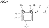
- the casing 23 of the radar 20 is fixed to a case 30 made of a resin. Holes 30h that are open in the front-rear direction are formed in an upper left portion and an upper right portion of the case 30. Bolts 32 are inserted in the holes 30h of the case 30 and the holes 13h of the base member 13. The bolts 32 are fastened in the holes 30h and the holes 13h while the upper left portion and the upper right portion of the case 30 are pressed against the fold-back portions 13b of the base member 13 with a rubber mount 40 therebetween, thereby fixing the case 30 to the base member 13.
- the radar 20 is indirectly supported on the seat frame 10 with the case 30, the rubber mount 40 and the base member 13 therebetween.
- the rubber mount 40 is an example of a rubber member interposed between the seat frame 10 and the radar 20.
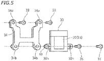
- a bracket 34 is interposed between the base member 13 and the case 30 made of a resin.
- the bracket 34 is made of a metal.
- Holes 34a that are open in the front-rear direction are formed in an upper left portion and an upper right portion of the bracket 34.
- Holes 34b that are open in the front-rear direction are formed in a lower left portion and a lower right portion of the bracket 34.
- Holes 30h that are open in the front-rear direction are formed in a lower left portion and a lower right portion of the case 30.
- Bolts 33 are inserted in the holes 34a in the upper left portion and the upper right portion of the bracket 34 and the holes 13h of the base member 13 (see FIG. 3 ).
- Bolts 35 are inserted in the holes 34b in the lower left portion and the lower right portion of the bracket 34 and the holes 30h of the case 30.
- the bolts 35 are fastened in the holes 30h and the holes 34b while the case 30 is pressed against the bracket 34 with the rubber mount 40 therebetween, thereby fixing the case 30 to the bracket 34.
- the bolts 33 are fastened in the holes 34a and the holes 13h while the bracket 34 is pressed against the fold-back portion 13b of the base member 13 (see FIG. 3 ), thereby fixing the bracket 34 to the base member 13.
- the radar 20 is indirectly supported on the seat frame 10 with the case 30, the rubber mount 40, the bracket 34 and the base member 13 therebetween.
- the bracket 34 is an example of the support member that supports the radar 20.
- a bracket 36 is interposed between the seat frame 10 and the case 30 made of a resin.
- the bracket 36 is made of a metal.
- bosses 10S are welded to a lower portion of the left seat frame 10L and the right seat frame 10R. Holes 10h that are open downward are formed in the bosses 10S.
- Holes 36a that are open in the up-down direction are formed in an upper left portion and an upper right portion of the bracket 36.
- Holes 36b that are open in the front-rear direction are formed in a lower left portion and a lower right portion of the bracket 36.
- the bolts 33 are inserted in the holes 36a in the upper left portion and the upper right portion of the bracket 36 and the holes 10h of the bosses 10S.
- the bolts 35 are inserted in the holes 36b of the lower left portion and the lower right portion of the bracket 36 and the holes 30h of the case 30.
- the bolts 35 are fastened in the holes 30h and the holes 36b while the case 30 is pressed against the bracket 36 with the rubber mount 40 therebetween, thereby fixing the case 30 to the bracket 36.
- the bolts 33 are fastened in the holes 36a and the holes 10h while the bracket 36 is pressed against the bosses 10S of the seat frame 10, thereby fixing the bracket 36 to the seat frame 10.
- the bracket 36 is an example of the support member that supports the radar 20.
- the radar 20 is arranged forward relative to the rear end 14b of the tail light 14, downward relative to an upper end 10t of the seat frame 10, rearward relative to the front end 12f of the rear fender 12, and upward relative to a lower end 12d of the rear fender 12.
- the entirety of the radar 20 is arranged forward relative to the rear end 14b of the tail light 14, downward relative to the upper end 10t of the seat frame 10, rearward relative to the front end 12f of the rear fender 12, and upward relative to the lower end 12d of the rear fender 12.
- the radar 20 is arranged downward relative to a lower end 14d of the tail light 14.
- T20 denotes the triangle that connects together a front end 14f of the tail light 14, the upper end 12t of the rear fender 12 and the lower end 12d of the rear fender 12 as the vehicle is viewed from the side.
- at least a portion of the radar 20 is located inside the triangle T20.
- a front end 20f of the radar 20 is located forward relative to the rear end 10b of the seat frame 10.
- a rear end 20b of the radar 20 is located rearward relative to the rear end 10b of the seat frame 10.
- the front end 20f of the radar 20 is located forward relative to the front end 14f of the tail light 14.
- the rear end 20b of the radar 20 is located rearward relative to the front end 14f of the tail light 14.
- the rear end 20b of the radar 20 is located forward relative to the rear end 14b of the tail light 14.
- the license plate 15 is supported on the rear fender 12.
- the license plate 15 is arranged downward of the tail light 14.
- the radar 20 is arranged upward relative to the license plate 15. At least a portion of the radar 20 is arranged forward relative to the license plate 15. Here, the entirety of the radar 20 is arranged forward relative to the license plate 15.
- a luggage box 16 as an optional accessory can be attached rearward of the seat 9.
- the luggage box 16 is arranged upward of the tail light 14.
- the radar 20 is arranged downward of the luggage box 16.
- the radar 20 is arranged forward of the luggage box 16.
- the motorcycle 1 according to the first embodiment is configured as described above.
- the radar 20 is arranged forward relative to the rear end 14b of the tail light 14, downward relative to the upper end 10t of the seat frame 10, rearward relative to the front end 12f of the rear fender 12 and upward relative to the lower end 12d of the rear fender 12.
- the radar 20 is less likely to block emitted light from the tail light 14.
- the motorcycle 1 it is possible to ensure the visibility of the tail light 14 while having a relatively large radar 20.
- the radar 20 does not block the tail light 14 from illuminating the license plate 15. Therefore, it is possible to ensure the visibility of the license plate 15.
- the radar 20 is supported on the seat frame 10.
- the seat frame 10 has a high rigidity and less likely to flex. Therefore, the radar 20 is less influenced by vibration as compared with a case where the radar 20 is supported on the rear fender 12 or the seat cowl 11.
- the motorcycle 1 in which the radar 20 does not block emitted light from the tail light 14 and is less likely to be influenced by vibration.
- mud, etc., which is rolled up from the road surface is blocked by the rear fender 12, and it is possible to sufficiently prevent mud, etc., from adhering to the radar 20.
- the bracket 34 (see FIG. 5 ) may be fixed to the base member 13, and the radar 20 may be supported by the bracket 34. Then, it is possible to stably support the radar 20. Therefore, it is possible to effectively suppress vibration of the radar 20 while the motorcycle 1 is running.
- the bracket 36 (see FIG. 6 ) may be fixed to the left seat frame 10L and the right seat frame 10R, and the radar 20 may be supported by the bracket 36. Then, it is possible to stably support the radar 20. Therefore, it is possible to effectively suppress vibration of the radar 20 while the motorcycle 1 is running.
- the support member 18 that supports the radar 20 may extend rearward and downward from the seat frame 10. Then, the support member 18 and the radar 20 can be arranged in a compact arrangement.
- a rubber-made member may be interposed between the seat frame 10 and the radar 20. Then, vibration of the seat frame 10 is less likely to be transmitted to the radar 20. Therefore, it is possible to suppress vibration of the radar 20.
- the rubber-made member is not limited to a cylindrical rubber mount 40.
- the tail light 14 is formed as a thin-type tail light in the present embodiment as shown in FIG. 2 .
- the dimension LB14 of the tail light 14 in the second direction LB is smaller than the dimension LA14 thereof in the first direction LA. Since the tail light 14 is of a thin type as described above, the radar 20 is less likely to block emitted light from the tail light 14.
- the tail light 14 and the radar 20 are arranged in a compact arrangement.
- FIG. 7 is an enlarged side view showing a rear portion of the motorcycle 1 according to the second embodiment.
- FIG. 8 is a back view showing a rear portion of the motorcycle 1 according to the second embodiment.
- like members to those of the first embodiment are denoted by like reference signs.
- the motorcycle 1 includes the seat frame 10, the seat cowl 11, the tail light 14, the rear fender 12, the license plate 15 and the radar 20. Note that FIG. 7 does not show the rear wheel 3.
- Reference sign 6 denotes a grab bar.
- At least a portion of the radar 20 is arranged forward relative to the rear end 14b of the tail light 14, downward relative to the upper end 10t of the seat frame 10, rearward relative to the front end 12f of the rear fender 12 and upward relative to the lower end 12d of the rear fender 12.
- the entirety of the radar 20 is arranged forward relative to the rear end 14b of the tail light 14, downward relative to the upper end 10t of the seat frame 10, rearward relative to the front end 12f of the rear fender 12 and upward relative to the lower end 12d of the rear fender 12.
- the radar 20 is supported on the seat frame 10.
- various structures described above may preferably be used, for example.
- the dimension of the casing 23 of the radar 20 in the front-rear direction is smaller than the dimension thereof in the up-down direction and the left-right direction.
- left and right flashers 24L and 24R are attached to the rear fender 12.
- the radar 20 is arranged upward relative to the flashers 24L and 24R.
- the front end 20f of the radar 20 is located forward relative to the rear end 10b of the seat frame 10.
- the rear end 20b of the radar 20 is located rearward relative to the rear end 10b of the seat frame 10.
- the front end 20f of the radar 20 is located forward relative to the front end 14f of the tail light 14.
- the rear end 20b of the radar 20 is located forward relative to the front end 14f of the tail light 14.
- the rear end 20b of the radar 20 is located forward relative to the rear end 14b of the tail light 14.
- the seat frame 10 is made of a metal, and the seat cowl 11 and the rear fender 12 are made of a synthetic resin.
- the seat cowl 11 and the rear fender 12 are made of a synthetic resin.
- these materials there is no particular limitation on these materials.
- the motorcycle 1 in which the radar 20 does not block emitted light from the tail light 14 and is less likely to be influenced by vibration.
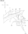
- FIG. 9 is an enlarged side view showing a rear portion of the motorcycle 1 according to the third embodiment.
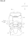
- FIG. 10 is a back view showing a rear portion of the motorcycle 1 according to the third embodiment.
- like members to those of the first embodiment and the second embodiment are denoted by like reference signs.
- the motorcycle 1 includes the seat frame 10, the seat cowl 11, the rear fender 12, the license plate 15 and the radar 20.
- FIG. 9 does not show the rear wheel 3.
- the tail light 14 functions also as a flasher. As shown in FIG. 10 , the tail light 14 includes a left tail light 14L and a right tail light 14R. The left tail light 14L and the right tail light 14R are arranged in left-right symmetry with respect to the vehicle center line CL. The position of the left tail light 14L in the front-rear direction and the up-down direction is the same as that of the right tail light 14R.
- At least a portion of the radar 20 is arranged forward relative to the rear end 14b of the tail light 14, downward relative to the upper end 10t of the seat frame 10, rearward relative to the front end 12f of the rear fender 12 and upward relative to the lower end 12d of the rear fender 12.
- the entirety of the radar 20 is arranged forward relative to the rear end 14b of the tail light 14, downward relative to the upper end 10t of the seat frame 10, rearward relative to the front end 12f of the rear fender 12 and upward relative to the lower end 12d of the rear fender 12.
- the radar 20 is supported on the seat frame 10.
- various structures described above may preferably be used, for example.
- the dimension of the casing 23 of the radar 20 in the front-rear direction is smaller than the dimension thereof in the up-down direction and the left-right direction.
- the tail light 14 is attached to the rear fender 12.
- the radar 20 is arranged upward relative to an upper end 14t of the tail light 14.
- the front end 20f of the radar 20 is located forward relative to the rear end 10b of the seat frame 10.
- the rear end 20b of the radar 20 is located rearward relative to the rear end 10b of the seat frame 10.
- the front end 20f of the radar 20 is located forward relative to the front end 14f of the tail light 14.
- the rear end 20b of the radar 20 is located rearward relative to the front end 14f of the tail light 14.
- the rear end 20b of the radar 20 is located forward relative to the rear end 14b of the tail light 14.
- the seat frame 10 is made of a metal, and the seat cowl 11 and the rear fender 12 are made of a synthetic resin.
- the seat cowl 11 and the rear fender 12 are made of a synthetic resin.
- these materials there is no particular limitation on these materials.
- the motorcycle 1 in which the radar 20 does not block emitted light from the tail light 14 and is less likely to be influenced by vibration.
- a straddled vehicle refers to a vehicle that is straddled by a passenger.
- a straddled vehicle is not limited to the motorcycle 1.
- a straddled vehicle may be an auto tricycle, an ATV (All Terrain Vehicle) or a snowmobile, for example.
Landscapes
- Engineering & Computer Science (AREA)
- Mechanical Engineering (AREA)
- Radar Systems Or Details Thereof (AREA)
- Automatic Cycles, And Cycles In General (AREA)
Abstract
Description
- The present invention relates to a straddled vehicle having a radar on a rear portion of the vehicle body.
- Straddled vehicles having a radar on a rear portion of the vehicle body have been known in the art. Such straddled vehicles, with the radar, can detect other vehicles coming close from behind. The radar includes a transmitter that transmits radio waves, a receiver that receives radio waves (reflected waves) that have been reflected off objects such as other vehicles, an antenna, and a casing that houses these components.
- The higher the performance of a radar, the larger the volume of the casing and the weight of the radar tend to be. However, a tail light and a rear fender are arranged on a rear portion of a straddled vehicle, and the space for installment of a radar is limited. Moreover, a radar needs to be arranged so as not to block emitted light from the tail light. It is not easy to arrange a large casing on a rear portion of a straddled vehicle.
- In view of this, the transmitter and the receiver of a radar may be housed in separate casings, thereby reducing the volume per casing. However, if the transmitter and the receiver are housed in separate casings, it will be more difficult to route wires that connect them together.
-
FIG. 2 ofJP 2017-218133 A JP 2017-218133 A - A straddled vehicle vibrates when, for example, running on an uneven road surface. Normally, a rear fender is made light in weight in order to reduce the weight of the vehicle body. The rigidity of a rear fender is relatively low. Therefore, if a large and heavy radar is attached to a rear fender, the radar is likely to be influenced by vibration as the rear fender bends due to vibration while running. In view of this, the rigidity of the rear fender may be increased so that the radar is less likely to be influenced by vibration. However, an attempt to increase the rigidity of the rear fender will increase the size and the weight of the rear fender.
- The radar may be arranged upward of the tail light by being attached to the seat cowl. By arranging the radar upward of the tail light, it is possible to prevent the radar from blocking emitted light from the tail light. However, as is the rear fender, the seat cowl is a member whose rigidity is relatively low. Also when the radar is attached to the seat cowl, similar problems to those described above will occur. If a large radar is arranged upward of the tail light, the passenger's comfort may lower. Some straddled vehicle users prefer to attach a luggage box as an optional accessory upward of the tail light. However, such a luggage box cannot be attached if a large radar is arranged upward of the tail light.
- It is an object of the present invention to provide a straddled vehicle in which a radar provided on a rear portion of the vehicle body does not block emitted light from the tail light and is less likely to be influenced by vibration. According to the present invention said object is solved by a straddled vehicle having the features of
independent claim 1. Preferred embodiments are laid down in the dependent claims. - A straddled vehicle disclosed herein includes: a seat frame extending rearward and upward; a seat supported on the seat frame; a rear fender extending rearward and downward, the rear fender having a front end located forward relative to a rear end of the seat frame; a tail light having a rear end located rearward relative to a rear end of the seat; and a radar. The radar includes a transmitter that transmits radio waves, a receiver that receives radio waves, and a casing that houses the transmitter and the receiver. The radar is supported on the seat frame. At least a portion of the radar is arranged forward relative to a rear end of the tail light, downward relative to an upper end of the seat frame, rearward relative to a front end of the rear fender and upward relative to a lower end of the rear fender.
- With the straddled vehicle described above, at least a portion of the radar is arranged forward relative to the rear end of the tail light, downward relative to the upper end of the seat frame, rearward relative to the front end of the rear fender and upward relative to the lower end of the rear fender. Therefore, even a relatively large radar can be arranged in a rear portion of the vehicle body without difficulty. The radar is less likely to block emitted light from the tail light. With the straddled vehicle described above, the radar is supported on the seat frame. As compared with a case where the radar is supported on the rear fender or the seat cowl, the radar is less likely to be influenced by vibration. Therefore, it is possible to provide a straddled vehicle in which a radar does not block emitted light from the tail light and is less likely to be influenced by vibration.
- The straddled vehicle may include a seat cowl arranged sideward of the seat frame. It is preferred that the radar is not supported either one of the rear fender and the seat cowl.
- According to a preferred embodiment, the seat frame includes a left seat frame and a right seat frame arranged rightward of the left seat frame. The straddled vehicle includes: a base member fixed to the left seat frame and the right seat frame; and a support member fixed to the base member. The radar is supported on the support member.
- According to the embodiment described above, it is possible to stably support the radar. Thus, it is possible to suppress vibration of the radar.
- According to a preferred embodiment, the seat frame includes a left seat frame and a right seat frame arranged rightward of the left seat frame. The straddled vehicle includes a support member fixed to the left seat frame and the right seat frame. The radar is supported on the support member.
- According to the embodiment described above, it is possible to stably support the radar. Thus, it is possible to suppress vibration of the radar.
- According to a preferred embodiment, the support member extends rearward and downward.
- According to the embodiment described above, the support member and the radar can be arranged in a compact arrangement.
- According to a preferred embodiment, the straddled vehicle includes a rubber-made member interposed between the seat frame and the radar.
- According to the embodiment described above, vibration of the seat frame is less likely to be transmitted to the radar, and it is therefore possible to suppress vibration of the radar.
- According to a preferred embodiment, the tail light is arranged upward relative to an upper end of the rear fender. The radar is arranged downward relative to a lower end of the tail light.
- According to the embodiment described above, the radar is arranged in a compact arrangement without blocking emitted light from the tail light.
- According to a preferred embodiment, as the vehicle is viewed from the side, a direction of extension of a rear end portion of the seat frame is defined as a first direction and a direction perpendicular to the first direction is defined as a second direction, wherein a dimension of the tail light in the second direction is smaller than a dimension of the tail light in the first direction.
- According to the embodiment described above, the tail light is a thin-type tail light. The radar is arranged in a compact arrangement without blocking emitted light from the tail light.
- According to a preferred embodiment, the tail light is attached to the rear fender. The radar is arranged upward relative to an upper end of the tail light.
- According to the embodiment described above, the radar is arranged in a compact arrangement without blocking emitted light from the tail light.
- A front end of the radar may be located forward relative to a rear end of the seat frame.
- A rear end of the radar may be located rearward relative to a rear end of the seat frame.
- A front end of the radar may be located forward relative to a front end of the tail light.
- A rear end of the radar may be located forward relative to a rear end of the tail light.
- A dimension of the casing in a front-rear direction may be smaller than a dimension the casing in an up-down direction.
- According to the present invention, it is possible to provide a straddled vehicle in which a radar provided on a rear portion of the vehicle body does not block emitted light from the tail light and is less likely to be influenced by vibration.
-
-
FIG. 1 is a left side view showing a motorcycle according to a first embodiment. -
FIG. 2 is an enlarged view showing section II ofFIG. 1 . -
FIG. 3 is a perspective view showing a portion of an example of a radar support structure. -
FIG. 4 is a perspective view showing a radar and a case. -
FIG. 5 is an exploded perspective view showing a portion of another example of a radar support structure. -
FIG. 6 is an exploded perspective view showing another example of a radar support structure. -
FIG. 7 is a side view showing a rear portion of a motorcycle according to a second embodiment. -
FIG. 8 is a back view showing a rear portion of the motorcycle according to the second embodiment. -
FIG. 9 is a side view showing a rear portion of a motorcycle according to a third embodiment. -
FIG. 10 is a back view showing a rear portion of the motorcycle according to the third embodiment. - Embodiments of the present teaching will now be described with reference to the drawings.
FIG. 1 is a side view showing amotorcycle 1 according to one embodiment. Themotorcycle 1 includes afront wheel 2, arear wheel 3, avehicle body 4 supported on thefront wheel 2 and therear wheel 3, and an internal combustion engine (hereinafter referred to as an engine) 5 supported on thevehicle body 4. Thevehicle body 4 includes asteering shaft 8 to which a handle 7 is attached, and aseat 9 on which the rider is seated. - The terms front, rear, left, right, up and down, as used in the description below, refer to these directions as seen from a virtual passenger (not shown) seated on the
seat 9 while themotorcycle 1 is standing upright on a horizontal surface with no passenger and no load thereon, unless specified otherwise. The designations F, Re, L, R, U and D, as used in the figures, refer to front, rear, left, right, up and down, respectively. -
FIG. 2 shows section II ofFIG. 1 on an enlarged scale, and is an enlarged side view showing a rear portion of themotorcycle 1. As shown inFIG. 2 , themotorcycle 1 includes aleft seat frame 10, aseat cowl 11, atail light 14, arear fender 12, alicense plate 15 and aradar 20. - The
seat frame 10 extends rearward and upward. Theseat 9 is supported on theseat frame 10. Theseat cowl 11 is arranged sideward of theseat frame 10. Therear fender 12 extends rearward and downward. Theseat frame 10 is made of a metal, and theseat cowl 11 and therear fender 12 are made of a synthetic resin. Note however that there is no particular limitation on the materials of theseat frame 10, theseat cowl 11 and therear fender 12. Afront end 12f of therear fender 12 is located forward relative to arear end 10b of theseat frame 10. Arear end 14b of thetail light 14 is located rearward relative to arear end 9b of theseat 9. - The
tail light 14 is arranged upward relative to anupper end 12t of therear fender 12. In the present embodiment, thetail light 14 is formed as a thin-type tail light. As shown inFIG. 2 , as the vehicle is viewed from the side, the direction of extension of the rear end portion of theseat frame 10 is defined as the first direction LA and the direction perpendicular to the first direction LA is defined as the second direction LB. The dimension LB14 of thetail light 14 in the second direction LB is smaller than the dimension LA14 thereof in the first direction LA. LB14<LA14. - The
radar 20 includes atransmitter 21 that transmits radio waves, areceiver 22 that receives radio waves, and acasing 23 that houses thetransmitter 21 and thereceiver 22. Theradar 20 is a sensor for blind spot detection (rear blind spot detection function). Theradar 20 transmits radio waves and receives radio waves that have been reflected off objects such as other vehicles to detect the presence of objects such as other vehicles rearward of themotorcycle 1. Here, thetransmitter 21 is configured to transmit millimeter waves with high directivity. - The
casing 23 is formed in a rectangular shape. The dimension of thecasing 23 in the front-rear direction is smaller than the dimension of thecasing 23 in the up-down direction. The dimension of thecasing 23 in the front-rear direction is smaller than the dimension of thecasing 23 in the left-right direction. Note however that the shape of thecasing 23 disclosed herein is merely an example. There is no particular limitation on the shape of thecasing 23. - The
radar 20 is supported on theseat frame 10. Here, theradar 20 is supported so as to be suspended from theseat frame 10. Theseat frame 10 is configured to support the load of theradar 20. Theradar 20 is not supported by either therear fender 12 or theseat cowl 11. Therear fender 12 and theseat cowl 11 do not support the load of theradar 20. Theradar 20 is attached to asupport member 18 fixed to theseat frame 10, for example. Here, thesupport member 18 extends rearward and downward from theseat frame 10. Note however that there is no particular limitation on the structure for supporting theradar 20 on the seat frame 10 (hereinafter referred to as the radar support structure). The radar support structure may be a structure as described below, for example. - In an example of the radar support structure, as shown in
FIG. 3 , theseat frame 10 includes aleft seat frame 10L, and aright seat frame 10R arranged rightward of theleft seat frame 10L. Abase member 13 is fixed to theleft seat frame 10L and theright seat frame 10R. Thebase member 13 is provided so as to bridge from theleft seat frame 10L to theright seat frame 10R. Note that theleft seat frame 10L, theright seat frame 10R and thebase member 13 are all made of a metal. Thebase member 13 includes ahorizontal plate portion 13a, and a plurality of fold-back portions 13b extending upward from the rear end of thehorizontal plate portion 13a.Holes 13h that are open in the front-rear direction are formed in the fold-back portions 13b. - As shown in
FIG. 4 , thecasing 23 of theradar 20 is fixed to acase 30 made of a resin.Holes 30h that are open in the front-rear direction are formed in an upper left portion and an upper right portion of thecase 30.Bolts 32 are inserted in theholes 30h of thecase 30 and theholes 13h of thebase member 13. Thebolts 32 are fastened in theholes 30h and theholes 13h while the upper left portion and the upper right portion of thecase 30 are pressed against the fold-back portions 13b of thebase member 13 with arubber mount 40 therebetween, thereby fixing thecase 30 to thebase member 13. Thus, theradar 20 is indirectly supported on theseat frame 10 with thecase 30, therubber mount 40 and thebase member 13 therebetween. Note that therubber mount 40 is an example of a rubber member interposed between theseat frame 10 and theradar 20. - In another example of the radar support structure, as shown in
FIG. 5 , abracket 34 is interposed between thebase member 13 and thecase 30 made of a resin. Here, thebracket 34 is made of a metal.Holes 34a that are open in the front-rear direction are formed in an upper left portion and an upper right portion of thebracket 34.Holes 34b that are open in the front-rear direction are formed in a lower left portion and a lower right portion of thebracket 34.Holes 30h that are open in the front-rear direction are formed in a lower left portion and a lower right portion of thecase 30. -
Bolts 33 are inserted in theholes 34a in the upper left portion and the upper right portion of thebracket 34 and theholes 13h of the base member 13 (seeFIG. 3 ).Bolts 35 are inserted in theholes 34b in the lower left portion and the lower right portion of thebracket 34 and theholes 30h of thecase 30. Thebolts 35 are fastened in theholes 30h and theholes 34b while thecase 30 is pressed against thebracket 34 with therubber mount 40 therebetween, thereby fixing thecase 30 to thebracket 34. Thebolts 33 are fastened in theholes 34a and theholes 13h while thebracket 34 is pressed against the fold-back portion 13b of the base member 13 (seeFIG. 3 ), thereby fixing thebracket 34 to thebase member 13. Thus, theradar 20 is indirectly supported on theseat frame 10 with thecase 30, therubber mount 40, thebracket 34 and thebase member 13 therebetween. Note that thebracket 34 is an example of the support member that supports theradar 20. - In another example of the radar support structure, as shown in
FIG. 6 , abracket 36 is interposed between theseat frame 10 and thecase 30 made of a resin. Here, thebracket 36 is made of a metal. In this example,bosses 10S are welded to a lower portion of theleft seat frame 10L and theright seat frame 10R.Holes 10h that are open downward are formed in thebosses 10S.Holes 36a that are open in the up-down direction are formed in an upper left portion and an upper right portion of thebracket 36.Holes 36b that are open in the front-rear direction are formed in a lower left portion and a lower right portion of thebracket 36. - The
bolts 33 are inserted in theholes 36a in the upper left portion and the upper right portion of thebracket 36 and theholes 10h of thebosses 10S. Thebolts 35 are inserted in theholes 36b of the lower left portion and the lower right portion of thebracket 36 and theholes 30h of thecase 30. Thebolts 35 are fastened in theholes 30h and theholes 36b while thecase 30 is pressed against thebracket 36 with therubber mount 40 therebetween, thereby fixing thecase 30 to thebracket 36. Thebolts 33 are fastened in theholes 36a and theholes 10h while thebracket 36 is pressed against thebosses 10S of theseat frame 10, thereby fixing thebracket 36 to theseat frame 10. Thus, theradar 20 is indirectly supported on theseat frame 10 with thecase 30, therubber mount 40, thebracket 36 and theboss 10S therebetween. Thebracket 36 is an example of the support member that supports theradar 20. - As shown in
FIG. 2 , at least a portion of theradar 20 is arranged forward relative to therear end 14b of thetail light 14, downward relative to anupper end 10t of theseat frame 10, rearward relative to thefront end 12f of therear fender 12, and upward relative to alower end 12d of therear fender 12. Here, the entirety of theradar 20 is arranged forward relative to therear end 14b of thetail light 14, downward relative to theupper end 10t of theseat frame 10, rearward relative to thefront end 12f of therear fender 12, and upward relative to thelower end 12d of therear fender 12. Theradar 20 is arranged downward relative to alower end 14d of thetail light 14. - As shown in
FIG. 2 , T20 denotes the triangle that connects together afront end 14f of thetail light 14, theupper end 12t of therear fender 12 and thelower end 12d of therear fender 12 as the vehicle is viewed from the side. Here, at least a portion of theradar 20 is located inside the triangle T20. - A
front end 20f of theradar 20 is located forward relative to therear end 10b of theseat frame 10. Arear end 20b of theradar 20 is located rearward relative to therear end 10b of theseat frame 10. Thefront end 20f of theradar 20 is located forward relative to thefront end 14f of thetail light 14. Therear end 20b of theradar 20 is located rearward relative to thefront end 14f of thetail light 14. Therear end 20b of theradar 20 is located forward relative to therear end 14b of thetail light 14. - The
license plate 15 is supported on therear fender 12. Thelicense plate 15 is arranged downward of thetail light 14. Theradar 20 is arranged upward relative to thelicense plate 15. At least a portion of theradar 20 is arranged forward relative to thelicense plate 15. Here, the entirety of theradar 20 is arranged forward relative to thelicense plate 15. - As shown in
FIG. 2 , aluggage box 16 as an optional accessory can be attached rearward of theseat 9. Theluggage box 16 is arranged upward of thetail light 14. Theradar 20 is arranged downward of theluggage box 16. Theradar 20 is arranged forward of theluggage box 16. Themotorcycle 1 according to the first embodiment is configured as described above. - As described above, with the
motorcycle 1 according to the present embodiment, at least a portion of theradar 20 is arranged forward relative to therear end 14b of thetail light 14, downward relative to theupper end 10t of theseat frame 10, rearward relative to thefront end 12f of therear fender 12 and upward relative to thelower end 12d of therear fender 12. Thus, even a relativelylarge radar 20 can be arranged in a rear portion of the vehicle body without difficulty. Theradar 20 is less likely to block emitted light from thetail light 14. With themotorcycle 1, it is possible to ensure the visibility of thetail light 14 while having a relativelylarge radar 20. Theradar 20 does not block thetail light 14 from illuminating thelicense plate 15. Therefore, it is possible to ensure the visibility of thelicense plate 15. - With the
motorcycle 1, theradar 20 is supported on theseat frame 10. As compared with therear fender 12 and theseat cowl 11, theseat frame 10 has a high rigidity and less likely to flex. Therefore, theradar 20 is less influenced by vibration as compared with a case where theradar 20 is supported on therear fender 12 or theseat cowl 11. - Thus, according to the present embodiment, it is possible to obtain the
motorcycle 1 in which theradar 20 does not block emitted light from thetail light 14 and is less likely to be influenced by vibration. - According to the present embodiment, mud, etc., which is rolled up from the road surface is blocked by the
rear fender 12, and it is possible to sufficiently prevent mud, etc., from adhering to theradar 20. - As described above, there is no particular limitation on the structure for supporting the
radar 20 on theseat frame 10. For example, the bracket 34 (seeFIG. 5 ) may be fixed to thebase member 13, and theradar 20 may be supported by thebracket 34. Then, it is possible to stably support theradar 20. Therefore, it is possible to effectively suppress vibration of theradar 20 while themotorcycle 1 is running. - The bracket 36 (see
FIG. 6 ) may be fixed to theleft seat frame 10L and theright seat frame 10R, and theradar 20 may be supported by thebracket 36. Then, it is possible to stably support theradar 20. Therefore, it is possible to effectively suppress vibration of theradar 20 while themotorcycle 1 is running. - As shown in
FIG. 2 , thesupport member 18 that supports theradar 20 may extend rearward and downward from theseat frame 10. Then, thesupport member 18 and theradar 20 can be arranged in a compact arrangement. - As is the
rubber mount 40 described above, a rubber-made member may be interposed between theseat frame 10 and theradar 20. Then, vibration of theseat frame 10 is less likely to be transmitted to theradar 20. Therefore, it is possible to suppress vibration of theradar 20. Note that the rubber-made member is not limited to acylindrical rubber mount 40. - While there is no particular limitation on the shape of the
tail light 14, thetail light 14 is formed as a thin-type tail light in the present embodiment as shown inFIG. 2 . The dimension LB14 of thetail light 14 in the second direction LB is smaller than the dimension LA14 thereof in the first direction LA. Since thetail light 14 is of a thin type as described above, theradar 20 is less likely to block emitted light from thetail light 14. Thetail light 14 and theradar 20 are arranged in a compact arrangement. -
FIG. 7 is an enlarged side view showing a rear portion of themotorcycle 1 according to the second embodiment.FIG. 8 is a back view showing a rear portion of themotorcycle 1 according to the second embodiment. In the description below, like members to those of the first embodiment are denoted by like reference signs. - As shown in
FIG. 7 andFIG. 8 , as in the first embodiment, themotorcycle 1 includes theseat frame 10, theseat cowl 11, thetail light 14, therear fender 12, thelicense plate 15 and theradar 20. Note thatFIG. 7 does not show therear wheel 3.Reference sign 6 denotes a grab bar. - As shown in
FIG. 7 , also in the present embodiment, at least a portion of theradar 20 is arranged forward relative to therear end 14b of thetail light 14, downward relative to theupper end 10t of theseat frame 10, rearward relative to thefront end 12f of therear fender 12 and upward relative to thelower end 12d of therear fender 12. Here, the entirety of theradar 20 is arranged forward relative to therear end 14b of thetail light 14, downward relative to theupper end 10t of theseat frame 10, rearward relative to thefront end 12f of therear fender 12 and upward relative to thelower end 12d of therear fender 12. - As in the first embodiment, the
radar 20 is supported on theseat frame 10. As the structure for supporting theradar 20 on theseat frame 10, various structures described above may preferably be used, for example. The dimension of thecasing 23 of theradar 20 in the front-rear direction is smaller than the dimension thereof in the up-down direction and the left-right direction. - In the present embodiment, left and
right flashers rear fender 12. Theradar 20 is arranged upward relative to theflashers - The
front end 20f of theradar 20 is located forward relative to therear end 10b of theseat frame 10. Therear end 20b of theradar 20 is located rearward relative to therear end 10b of theseat frame 10. Thefront end 20f of theradar 20 is located forward relative to thefront end 14f of thetail light 14. Therear end 20b of theradar 20 is located forward relative to thefront end 14f of thetail light 14. Therear end 20b of theradar 20 is located forward relative to therear end 14b of thetail light 14. - As in the first embodiment, the
seat frame 10 is made of a metal, and theseat cowl 11 and therear fender 12 are made of a synthetic resin. However, there is no particular limitation on these materials. - Also in the present embodiment, it is possible to obtain the
motorcycle 1 in which theradar 20 does not block emitted light from thetail light 14 and is less likely to be influenced by vibration. -
FIG. 9 is an enlarged side view showing a rear portion of themotorcycle 1 according to the third embodiment.FIG. 10 is a back view showing a rear portion of themotorcycle 1 according to the third embodiment. In the description below, like members to those of the first embodiment and the second embodiment are denoted by like reference signs. - Also in the present embodiment, the
motorcycle 1 includes theseat frame 10, theseat cowl 11, therear fender 12, thelicense plate 15 and theradar 20.FIG. 9 does not show therear wheel 3. - In the present embodiment, the
tail light 14 functions also as a flasher. As shown inFIG. 10 , thetail light 14 includes aleft tail light 14L and aright tail light 14R. Theleft tail light 14L and theright tail light 14R are arranged in left-right symmetry with respect to the vehicle center line CL. The position of theleft tail light 14L in the front-rear direction and the up-down direction is the same as that of theright tail light 14R. - As shown in
FIG. 9 , also in the present embodiment, at least a portion of theradar 20 is arranged forward relative to therear end 14b of thetail light 14, downward relative to theupper end 10t of theseat frame 10, rearward relative to thefront end 12f of therear fender 12 and upward relative to thelower end 12d of therear fender 12. Here, the entirety of theradar 20 is arranged forward relative to therear end 14b of thetail light 14, downward relative to theupper end 10t of theseat frame 10, rearward relative to thefront end 12f of therear fender 12 and upward relative to thelower end 12d of therear fender 12. - As in the first embodiment and the second embodiment, the
radar 20 is supported on theseat frame 10. As the structure for supporting theradar 20 on theseat frame 10, various structures described above may preferably be used, for example. The dimension of thecasing 23 of theradar 20 in the front-rear direction is smaller than the dimension thereof in the up-down direction and the left-right direction. - In the present embodiment, the
tail light 14 is attached to therear fender 12. Theradar 20 is arranged upward relative to anupper end 14t of thetail light 14. - The
front end 20f of theradar 20 is located forward relative to therear end 10b of theseat frame 10. Therear end 20b of theradar 20 is located rearward relative to therear end 10b of theseat frame 10. Thefront end 20f of theradar 20 is located forward relative to thefront end 14f of thetail light 14. Therear end 20b of theradar 20 is located rearward relative to thefront end 14f of thetail light 14. Therear end 20b of theradar 20 is located forward relative to therear end 14b of thetail light 14. - As in the first embodiment and the second embodiment, the
seat frame 10 is made of a metal, and theseat cowl 11 and therear fender 12 are made of a synthetic resin. However, there is no particular limitation on these materials. - Also in the present embodiment, it is possible to obtain the
motorcycle 1 in which theradar 20 does not block emitted light from thetail light 14 and is less likely to be influenced by vibration. - Some embodiments have been described above. Note however that these embodiments are merely examples. Various other embodiments are possible.
- A straddled vehicle refers to a vehicle that is straddled by a passenger. A straddled vehicle is not limited to the
motorcycle 1. A straddled vehicle may be an auto tricycle, an ATV (All Terrain Vehicle) or a snowmobile, for example. - 1: Motorcycle (straddled vehicle), 9: Seat, 10: Seat frame, 10L: Left seat frame, 10R: Right seat frame, 11: Seat cowl, 12: Rear fender, 13: Base member, 14: Tail light, 18: Support member, 20: Radar, 21: Transmitter, 22: Receiver, 23: Casing, 34: Bracket (support member), 36: Bracket (support member), 40: Rubber mount (rubber-made member), LA: First direction, LB: Second direction
Claims (14)
- A straddled vehicle (1) comprising:a seat frame (10) extending rearward in vehicle front-rear direction and upward in vehicle up-down direction;a seat (9) supported on the seat frame (10);a rear fender (12) extending rearward in vehicle front-rear direction and downward in vehicle up-down direction, the rear fender (12) having a front end (12f) located forward relative to a rear end (10b) of the seat frame (10) in vehicle front-rear direction;a tail light (14) having a rear end (14b) located rearward relative to a rear end (9b) of the seat (9) in vehicle front-rear direction; anda radar (20) including a transmitter (21) that transmits radio waves, a receiver (22) that receives radio waves, and a casing (23) that houses the transmitter (21) and the receiver (22), wherein:the radar (20) is supported on the seat frame (10);at least a portion of the radar (20) is arranged forward relative to a rear end (14b) of the tail light (14) in vehicle front-rear direction, downward relative to an upper end (10t) of the seat frame (10) in vehicle up-down direction, rearward relative to a front end (12f) of the rear fender (12) in vehicle front-rear direction and upward relative to a lower end (12d) of the rear fender (12) in vehicle up-down direction.
- The straddled vehicle (1) according to claim 1, wherein a seat cowl (11) arranged sideward of the seat frame (10) in vehicle left-right direction; and
the radar (20) is not supported either one of the rear fender (12) and the seat cowl (11). - The straddled vehicle (1) according to claim 1 or 2, wherein the seat frame (10) includes a left seat frame (10L) and a right seat frame (10R) arranged rightward of the left seat frame (10L) in vehicle left-right direction;the straddled vehicle (1) includes:a base member (13) fixed to the left seat frame (10L) and the right seat frame (10R); anda support member (34) fixed to the base member (13); andthe radar (20) is supported on the support member (34).
- The straddled vehicle (1) according to claim 1 or 2, wherein the seat frame (10) includes a left seat frame (10L) and a right seat frame (10R) arranged rightward of the left seat frame (10L) in vehicle left-right direction;the straddled vehicle (1) includes a support member (36) fixed to the left seat frame (10L) and the right seat frame (10R); andthe radar (20) is supported on the support member (36).
- The straddled vehicle (1) according to claim 3 or 4, wherein the support member (34) extends rearward in vehicle front-rear direction and downward in vehicle up-down direction.
- The straddled vehicle (1) according to any one of claims 1 to 5, comprising a rubber-made member (40) interposed between the seat frame (10) and the radar (20).
- The straddled vehicle (1) according to any one of claims 1 to 6, wherein the tail light (14) is arranged upward relative to an upper end (12t) of the rear fender (12) in vehicle up-down direction; and
the radar (20) is arranged downward relative to a lower end (14d) of the tail light (14) in vehicle up-down direction. - The straddled vehicle (1) according to claim 7, wherein as the vehicle is viewed from the side, a direction of extension to a rear end portion of the seat frame (10) in vehicle front-rear direction is defined as a first direction (LA) and a direction perpendicular to the first direction (LA) is defined as a second direction (LB), wherein a dimension (LB14) of the tail light (14) in the second direction (LB) is smaller than a dimension (LA14) of the tail light (14) in the first direction (LA).
- The straddled vehicle (1) according to any one of claims 1 to 6, wherein the tail light (14) is attached to the rear fender (12); and
the radar (20) is arranged upward relative to an upper end (14t) of the tail light (14) in vehicle up-down direction. - The straddled vehicle (1) according to any one of claims 1 to 9, wherein a front end (20f) of the radar (20) is located forward relative to a rear end (10b) of the seat frame (10) in vehicle front-rear direction.
- The straddled vehicle (1) according to any one of claims 1 to 10, wherein a rear end (20b) of the radar (20) is located rearward relative to a rear end (10b) of the seat frame (10) in vehicle front-rear direction.
- The straddled vehicle (1) according to any one of claims 1 to 11, wherein a front end (20f) of the radar (20) is located forward relative to a front end (14f) of the tail light (14) in vehicle front-rear direction.
- The straddled vehicle (1) according to any one of claims 1 to 12, wherein a rear end (20b) of the radar (20) is located forward relative to a rear end (14b) of the tail light (14) in vehicle front-rear direction.
- The straddled vehicle (1) according to any one of claims 1 to 13, wherein a dimension of the casing (23) in vehicle front-rear direction is smaller than a dimension of the casing (23) in vehicle up-down direction.
Applications Claiming Priority (1)
| Application Number | Priority Date | Filing Date | Title |
|---|---|---|---|
| JP2021044897A JP2022144055A (en) | 2021-03-18 | 2021-03-18 | Saddle riding vehicle |
Publications (2)
| Publication Number | Publication Date |
|---|---|
| EP4059794A1 true EP4059794A1 (en) | 2022-09-21 |
| EP4059794B1 EP4059794B1 (en) | 2025-11-26 |
Family
ID=80819810
Family Applications (1)
| Application Number | Title | Priority Date | Filing Date |
|---|---|---|---|
| EP22162971.0A Active EP4059794B1 (en) | 2021-03-18 | 2022-03-18 | Straddled vehicle with rear radar |
Country Status (3)
| Country | Link |
|---|---|
| US (1) | US20220297783A1 (en) |
| EP (1) | EP4059794B1 (en) |
| JP (1) | JP2022144055A (en) |
Cited By (1)
| Publication number | Priority date | Publication date | Assignee | Title |
|---|---|---|---|---|
| WO2026099881A1 (en) * | 2024-11-11 | 2026-05-15 | Tvs Motor Company Limited | A vehicle |
Families Citing this family (4)
| Publication number | Priority date | Publication date | Assignee | Title |
|---|---|---|---|---|
| JP7066839B2 (en) * | 2018-05-23 | 2022-05-13 | 本田技研工業株式会社 | Saddle-type vehicle |
| JP2025032897A (en) * | 2023-08-28 | 2025-03-12 | カワサキモータース株式会社 | Saddle-type vehicle |
| WO2025191577A1 (en) * | 2024-03-15 | 2025-09-18 | Tvs Motor Company Limited | A frame assembly for a vehicle |
| JP2025167116A (en) * | 2024-04-25 | 2025-11-07 | ヤマハ発動機株式会社 | Saddle-type vehicle |
Citations (5)
| Publication number | Priority date | Publication date | Assignee | Title |
|---|---|---|---|---|
| JP2017091138A (en) * | 2015-11-09 | 2017-05-25 | スズキ株式会社 | Alarm system and saddling vehicle having the same |
| JP2017218133A (en) | 2016-06-10 | 2017-12-14 | スズキ株式会社 | Position lighting device |
| EP3453600A1 (en) * | 2017-09-11 | 2019-03-13 | Kawasaki Jukogyo Kabushiki Kaisha | Motorcycle |
| WO2020129789A1 (en) * | 2018-12-21 | 2020-06-25 | 川崎重工業株式会社 | Saddle-ridden vehicle |
| US20210061391A1 (en) * | 2018-05-23 | 2021-03-04 | Honda Motor Co., Ltd. | Straddle type vehicle |
Family Cites Families (7)
| Publication number | Priority date | Publication date | Assignee | Title |
|---|---|---|---|---|
| JP5307288B2 (en) * | 2010-02-23 | 2013-10-02 | 本田技研工業株式会社 | Rear structure of motorcycle |
| JP2014189104A (en) * | 2013-03-26 | 2014-10-06 | Yamaha Motor Co Ltd | Motorcycle |
| CA2924948C (en) * | 2013-09-27 | 2018-01-09 | Honda Motor Co., Ltd. | Two-wheeled motor vehicle |
| JP6172686B2 (en) * | 2015-08-07 | 2017-08-02 | 本田技研工業株式会社 | Rear structure in motorcycle |
| JP2017074820A (en) * | 2015-10-13 | 2017-04-20 | スズキ株式会社 | Notification system for vehicle |
| JP6214706B2 (en) * | 2016-03-30 | 2017-10-18 | 本田技研工業株式会社 | Rear structure of saddle-ride type vehicle |
| WO2019186948A1 (en) * | 2018-03-29 | 2019-10-03 | 本田技研工業株式会社 | Straddle type vehicle |
-
2021
- 2021-03-18 JP JP2021044897A patent/JP2022144055A/en active Pending
-
2022
- 2022-03-17 US US17/697,817 patent/US20220297783A1/en active Pending
- 2022-03-18 EP EP22162971.0A patent/EP4059794B1/en active Active
Patent Citations (5)
| Publication number | Priority date | Publication date | Assignee | Title |
|---|---|---|---|---|
| JP2017091138A (en) * | 2015-11-09 | 2017-05-25 | スズキ株式会社 | Alarm system and saddling vehicle having the same |
| JP2017218133A (en) | 2016-06-10 | 2017-12-14 | スズキ株式会社 | Position lighting device |
| EP3453600A1 (en) * | 2017-09-11 | 2019-03-13 | Kawasaki Jukogyo Kabushiki Kaisha | Motorcycle |
| US20210061391A1 (en) * | 2018-05-23 | 2021-03-04 | Honda Motor Co., Ltd. | Straddle type vehicle |
| WO2020129789A1 (en) * | 2018-12-21 | 2020-06-25 | 川崎重工業株式会社 | Saddle-ridden vehicle |
Cited By (1)
| Publication number | Priority date | Publication date | Assignee | Title |
|---|---|---|---|---|
| WO2026099881A1 (en) * | 2024-11-11 | 2026-05-15 | Tvs Motor Company Limited | A vehicle |
Also Published As
| Publication number | Publication date |
|---|---|
| JP2022144055A (en) | 2022-10-03 |
| US20220297783A1 (en) | 2022-09-22 |
| EP4059794B1 (en) | 2025-11-26 |
Similar Documents
| Publication | Publication Date | Title |
|---|---|---|
| EP4059794B1 (en) | Straddled vehicle with rear radar | |
| US9893415B2 (en) | Two-wheeled motor vehicle | |
| US11603159B2 (en) | Straddle type vehicle | |
| US11715873B2 (en) | Straddle type vehicle | |
| US8041507B2 (en) | Meter support structure | |
| JP7066839B2 (en) | Saddle-type vehicle | |
| US11807332B2 (en) | Straddle type vehicle | |
| JP2001352209A (en) | Antenna arrangement structure of motorcycle | |
| EP2180332B1 (en) | Motorcycle | |
| JP7060704B2 (en) | Saddle-type vehicle | |
| BR102012032381A2 (en) | MOTORCYCLE | |
| US7158884B2 (en) | Saddle-type vehicle equipped with a navigation system | |
| US6322238B1 (en) | Auxiliary lighting system | |
| JP2006126169A (en) | GPS built-in meter | |
| US20050117359A1 (en) | Structure for supporting headlamps for vehicle | |
| EP4688507A1 (en) | Motorcycle rear radar integration | |
| BRPI1002709B1 (en) | motorcycle | |
| BRPI1100143B1 (en) | SADDLE TYPE VEHICLE | |
| US12559191B2 (en) | Rideable saddle vehicle provided with detection unit | |
| US20250093500A1 (en) | Saddle with radar device for detecting nearby objects and causing warnings | |
| US20250074531A1 (en) | Straddle type vehicle | |
| JP7191963B2 (en) | Lean vehicle equipped with an antenna for inter-vehicle communication, and an antenna for inter-vehicle communication configured to be mounted on the lean vehicle | |
| JP6777170B2 (en) | Motorcycles and tricycles | |
| JP2000177667A (en) | Vehicle luggage loading device | |
| JPH09175323A (en) | Seatbelt anchor mounting structure |
Legal Events
| Date | Code | Title | Description |
|---|---|---|---|
| PUAI | Public reference made under article 153(3) epc to a published international application that has entered the european phase |
Free format text: ORIGINAL CODE: 0009012 |
|
| STAA | Information on the status of an ep patent application or granted ep patent |
Free format text: STATUS: THE APPLICATION HAS BEEN PUBLISHED |
|
| AK | Designated contracting states |
Kind code of ref document: A1 Designated state(s): AL AT BE BG CH CY CZ DE DK EE ES FI FR GB GR HR HU IE IS IT LI LT LU LV MC MK MT NL NO PL PT RO RS SE SI SK SM TR |
|
| STAA | Information on the status of an ep patent application or granted ep patent |
Free format text: STATUS: REQUEST FOR EXAMINATION WAS MADE |
|
| 17P | Request for examination filed |
Effective date: 20230227 |
|
| RBV | Designated contracting states (corrected) |
Designated state(s): AL AT BE BG CH CY CZ DE DK EE ES FI FR GB GR HR HU IE IS IT LI LT LU LV MC MK MT NL NO PL PT RO RS SE SI SK SM TR |
|
| STAA | Information on the status of an ep patent application or granted ep patent |
Free format text: STATUS: EXAMINATION IS IN PROGRESS |
|
| 17Q | First examination report despatched |
Effective date: 20230516 |
|
| P01 | Opt-out of the competence of the unified patent court (upc) registered |
Effective date: 20230527 |
|
| GRAP | Despatch of communication of intention to grant a patent |
Free format text: ORIGINAL CODE: EPIDOSNIGR1 |
|
| STAA | Information on the status of an ep patent application or granted ep patent |
Free format text: STATUS: GRANT OF PATENT IS INTENDED |
|
| INTG | Intention to grant announced |
Effective date: 20250805 |
|
| GRAS | Grant fee paid |
Free format text: ORIGINAL CODE: EPIDOSNIGR3 |
|
| GRAA | (expected) grant |
Free format text: ORIGINAL CODE: 0009210 |
|
| STAA | Information on the status of an ep patent application or granted ep patent |
Free format text: STATUS: THE PATENT HAS BEEN GRANTED |
|
| AK | Designated contracting states |
Kind code of ref document: B1 Designated state(s): AL AT BE BG CH CY CZ DE DK EE ES FI FR GB GR HR HU IE IS IT LI LT LU LV MC MK MT NL NO PL PT RO RS SE SI SK SM TR |
|
| REG | Reference to a national code |
Ref country code: CH Ref legal event code: F10 Free format text: ST27 STATUS EVENT CODE: U-0-0-F10-F00 (AS PROVIDED BY THE NATIONAL OFFICE) Effective date: 20251126 Ref country code: GB Ref legal event code: FG4D |
|
| REG | Reference to a national code |
Ref country code: DE Ref legal event code: R096 Ref document number: 602022025460 Country of ref document: DE |
|
| REG | Reference to a national code |
Ref country code: IE Ref legal event code: FG4D |
|
| REG | Reference to a national code |
Ref country code: NL Ref legal event code: MP Effective date: 20251126 |
|
| PG25 | Lapsed in a contracting state [announced via postgrant information from national office to epo] |
Ref country code: ES Free format text: LAPSE BECAUSE OF FAILURE TO SUBMIT A TRANSLATION OF THE DESCRIPTION OR TO PAY THE FEE WITHIN THE PRESCRIBED TIME-LIMIT Effective date: 20251126 |
|
| REG | Reference to a national code |
Ref country code: LT Ref legal event code: MG9D |
|
| PG25 | Lapsed in a contracting state [announced via postgrant information from national office to epo] |
Ref country code: NO Free format text: LAPSE BECAUSE OF FAILURE TO SUBMIT A TRANSLATION OF THE DESCRIPTION OR TO PAY THE FEE WITHIN THE PRESCRIBED TIME-LIMIT Effective date: 20260226 |
|
| PGFP | Annual fee paid to national office [announced via postgrant information from national office to epo] |
Ref country code: DE Payment date: 20260319 Year of fee payment: 5 |
|
| PG25 | Lapsed in a contracting state [announced via postgrant information from national office to epo] |
Ref country code: FI Free format text: LAPSE BECAUSE OF FAILURE TO SUBMIT A TRANSLATION OF THE DESCRIPTION OR TO PAY THE FEE WITHIN THE PRESCRIBED TIME-LIMIT Effective date: 20251126 Ref country code: HR Free format text: LAPSE BECAUSE OF FAILURE TO SUBMIT A TRANSLATION OF THE DESCRIPTION OR TO PAY THE FEE WITHIN THE PRESCRIBED TIME-LIMIT Effective date: 20251126 Ref country code: AT Free format text: LAPSE BECAUSE OF FAILURE TO SUBMIT A TRANSLATION OF THE DESCRIPTION OR TO PAY THE FEE WITHIN THE PRESCRIBED TIME-LIMIT Effective date: 20251126 |
|
| PGFP | Annual fee paid to national office [announced via postgrant information from national office to epo] |
Ref country code: AT Payment date: 20260301 Year of fee payment: 5 |
|
| PGFP | Annual fee paid to national office [announced via postgrant information from national office to epo] |
Ref country code: IT Payment date: 20260324 Year of fee payment: 5 |
|
| REG | Reference to a national code |
Ref country code: AT Ref legal event code: MK05 Ref document number: 1860799 Country of ref document: AT Kind code of ref document: T Effective date: 20251126 |
|
| PG25 | Lapsed in a contracting state [announced via postgrant information from national office to epo] |
Ref country code: NL Free format text: LAPSE BECAUSE OF FAILURE TO SUBMIT A TRANSLATION OF THE DESCRIPTION OR TO PAY THE FEE WITHIN THE PRESCRIBED TIME-LIMIT Effective date: 20251126 |
|
| PG25 | Lapsed in a contracting state [announced via postgrant information from national office to epo] |
Ref country code: RS Free format text: LAPSE BECAUSE OF FAILURE TO SUBMIT A TRANSLATION OF THE DESCRIPTION OR TO PAY THE FEE WITHIN THE PRESCRIBED TIME-LIMIT Effective date: 20260226 |
|
| PG25 | Lapsed in a contracting state [announced via postgrant information from national office to epo] |
Ref country code: IS Free format text: LAPSE BECAUSE OF FAILURE TO SUBMIT A TRANSLATION OF THE DESCRIPTION OR TO PAY THE FEE WITHIN THE PRESCRIBED TIME-LIMIT Effective date: 20260326 |
|
| PGFP | Annual fee paid to national office [announced via postgrant information from national office to epo] |
Ref country code: FR Payment date: 20260323 Year of fee payment: 5 |
|
| PG25 | Lapsed in a contracting state [announced via postgrant information from national office to epo] |
Ref country code: PT Free format text: LAPSE BECAUSE OF FAILURE TO SUBMIT A TRANSLATION OF THE DESCRIPTION OR TO PAY THE FEE WITHIN THE PRESCRIBED TIME-LIMIT Effective date: 20260326 |
|
| PG25 | Lapsed in a contracting state [announced via postgrant information from national office to epo] |
Ref country code: PL Free format text: LAPSE BECAUSE OF FAILURE TO SUBMIT A TRANSLATION OF THE DESCRIPTION OR TO PAY THE FEE WITHIN THE PRESCRIBED TIME-LIMIT Effective date: 20251126 |
|
| PG25 | Lapsed in a contracting state [announced via postgrant information from national office to epo] |
Ref country code: LV Free format text: LAPSE BECAUSE OF FAILURE TO SUBMIT A TRANSLATION OF THE DESCRIPTION OR TO PAY THE FEE WITHIN THE PRESCRIBED TIME-LIMIT Effective date: 20251126 |
|
| PG25 | Lapsed in a contracting state [announced via postgrant information from national office to epo] |
Ref country code: BG Free format text: LAPSE BECAUSE OF FAILURE TO SUBMIT A TRANSLATION OF THE DESCRIPTION OR TO PAY THE FEE WITHIN THE PRESCRIBED TIME-LIMIT Effective date: 20251126 |
|
| PG25 | Lapsed in a contracting state [announced via postgrant information from national office to epo] |
Ref country code: LT Free format text: LAPSE BECAUSE OF FAILURE TO SUBMIT A TRANSLATION OF THE DESCRIPTION OR TO PAY THE FEE WITHIN THE PRESCRIBED TIME-LIMIT Effective date: 20251126 |
|
| PG25 | Lapsed in a contracting state [announced via postgrant information from national office to epo] |
Ref country code: SM Free format text: LAPSE BECAUSE OF FAILURE TO SUBMIT A TRANSLATION OF THE DESCRIPTION OR TO PAY THE FEE WITHIN THE PRESCRIBED TIME-LIMIT Effective date: 20251126 |
|
| PG25 | Lapsed in a contracting state [announced via postgrant information from national office to epo] |
Ref country code: DK Free format text: LAPSE BECAUSE OF FAILURE TO SUBMIT A TRANSLATION OF THE DESCRIPTION OR TO PAY THE FEE WITHIN THE PRESCRIBED TIME-LIMIT Effective date: 20251126 |
|
| PG25 | Lapsed in a contracting state [announced via postgrant information from national office to epo] |
Ref country code: EE Free format text: LAPSE BECAUSE OF FAILURE TO SUBMIT A TRANSLATION OF THE DESCRIPTION OR TO PAY THE FEE WITHIN THE PRESCRIBED TIME-LIMIT Effective date: 20251126 |
|
| PG25 | Lapsed in a contracting state [announced via postgrant information from national office to epo] |
Ref country code: CZ Free format text: LAPSE BECAUSE OF FAILURE TO SUBMIT A TRANSLATION OF THE DESCRIPTION OR TO PAY THE FEE WITHIN THE PRESCRIBED TIME-LIMIT Effective date: 20251126 |
|
| PG25 | Lapsed in a contracting state [announced via postgrant information from national office to epo] |
Ref country code: SK Free format text: LAPSE BECAUSE OF FAILURE TO SUBMIT A TRANSLATION OF THE DESCRIPTION OR TO PAY THE FEE WITHIN THE PRESCRIBED TIME-LIMIT Effective date: 20251126 |
|
| PG25 | Lapsed in a contracting state [announced via postgrant information from national office to epo] |
Ref country code: SE Free format text: LAPSE BECAUSE OF FAILURE TO SUBMIT A TRANSLATION OF THE DESCRIPTION OR TO PAY THE FEE WITHIN THE PRESCRIBED TIME-LIMIT Effective date: 20251126 |