EP4059792B1 - Spring brake actuator for use in a vehicle, and use of a disc spring therein - Google Patents
Spring brake actuator for use in a vehicle, and use of a disc spring therein Download PDFInfo
- Publication number
- EP4059792B1 EP4059792B1 EP21162513.2A EP21162513A EP4059792B1 EP 4059792 B1 EP4059792 B1 EP 4059792B1 EP 21162513 A EP21162513 A EP 21162513A EP 4059792 B1 EP4059792 B1 EP 4059792B1
- Authority
- EP
- European Patent Office
- Prior art keywords
- spring
- brake actuator
- disc
- spring brake
- piston
- Prior art date
- Legal status (The legal status is an assumption and is not a legal conclusion. Google has not performed a legal analysis and makes no representation as to the accuracy of the status listed.)
- Active
Links
Images
Classifications
-
- B—PERFORMING OPERATIONS; TRANSPORTING
- B60—VEHICLES IN GENERAL
- B60T—VEHICLE BRAKE CONTROL SYSTEMS OR PARTS THEREOF; BRAKE CONTROL SYSTEMS OR PARTS THEREOF, IN GENERAL; ARRANGEMENT OF BRAKING ELEMENTS ON VEHICLES IN GENERAL; PORTABLE DEVICES FOR PREVENTING UNWANTED MOVEMENT OF VEHICLES; VEHICLE MODIFICATIONS TO FACILITATE COOLING OF BRAKES
- B60T17/00—Component parts, details, or accessories of power brake systems not covered by groups B60T8/00, B60T13/00 or B60T15/00, or presenting other characteristic features
- B60T17/08—Brake cylinders other than ultimate actuators
Definitions
- the invention relates to a spring brake actuator for use in a vehicle, in particular in a commercial vehicle, the spring brake actuator comprising a housing part having a housing part having a housing base, a piston that is located inside the housing and configured to move along a stroke axis from a retracted position towards an extended position such as to transmit a brake force, and a spring assembly mounted between the housing base and the piston, wherein in the spring assembly comprises an axis of action, preferably aligned in parallel to the stroke axis and is operatively coupled to the piston such as to store potential energy and the piston is in the retracted position and to move the piston towards the extended position by transforming potential energy into kinetic energy.
- Spring brake actuators of the aforementioned type are widely known in the industry.
- the aforementioned housing part is also referred to as a spring brake portion, and the core functionality of the spring assembly is to generate a parking or emergency brake function which is transmitted by the piston onwards to a brake mechanism.
- these spring brake actuators additionally comprise a service brake portion which interacts with the spring brake piston of the spring brake portion and comprises a push rod which is operatively coupled to the brake mechanism.
- the spring assembly in the spring brake portion of a spring brake actuator is held in a loaded state by pressurizing a spring brake chamber which is delimited in part by either the spring piston itself or a diaphragm which abuts against the piston. If pressure is released from the spring brake chamber, the spring assembly is allowed to release from its loaded state and move the piston from the retracted position towards its extended position. Depending on the suddenness of the pressure release, the expansion movement of the spring and thus the movement of the piston can be very rapid. Rapid movement is essential in order to provide the required suddenness of reaction for emergency functions. At the same time, considerable amounts of potential energy need to be stored by the spring assembly in order to provide sufficient suddenness of movement over the required stroke length.
- One exemplary commercial example for the aforementioned spring brake actuator would be the so-called Tri-Stop brake actuators of the applicant.
- EP 0 074 734 A2 discloses a spring brake actuator with a spring assembly inside the spring brake actuator, wherein the spring assembly comprises one disc spring.
- the spring assembly comprises one disc spring.
- the invention attains the aforementioned object by suggesting a spring brake actuator having the features of claim 1.
- the invention suggests a spring brake actuator of the initially mentioned type, wherein the spring assembly comprises at least one disc spring.
- the invention is based upon the realization that instead of conventional compression springs which have been used in spring assemblies before, either as conically, cylindrically or (bi-)convexly wound coil springs, a spring assembly having at least one disc spring would be suited to satisfy the need of generating considerable brake force. It has been found that the design needs of disc springs allow for space-saving installation inside the spring brake actuator and help to significantly reduce the overall size of the spring brake actuator in the direction of the axis of action.
- the deformation rate of a disc spring is not as linear as the deformation rate of a coil spring in general, but the inventors found out that linearity is not of utmost importance for providing the required braking functionality, such that a disc spring, or rather any given number of disc springs, may be employed in a spring actuator according to the invention without adverse effect.
- the functioning principle of the known spring brake actuators can be maintained:
- the spring brake piston is moved into the retracted position by applying pressure inside the housing part, thereby deforming the spring assembly with the at least one disc spring into a loaded position in which the energy use to deform the spring as stall as potential energy.
- the potential energy stored in the spring assembly is released and transformed into kinetic energy by moving the spring brake piston towards the extended position.
- the disc spring comprises a base body having a shell.
- the shell in the released state of the disc spring, the shell preferably comprises a frusto-conically shaped portion, said portion preferably defining an opening angle in a cross-sectional plane along the axis of action, wherein in the extended position of the piston, the opening angle is smaller than in the retracted position.
- the shell preferably comprises a planar portion extending in a plane perpendicular to the axis of action, when in the released state of the disc spring. The planar portion of the disc spring helps to smooth out the overall stiffness of the disc spring and contributes to a softer initial deformation.
- the disc spring according to the invention may also be formed as a planar washer spring, or a frusto-conically shaped washer spring, also referred to as Belleville spring.
- the disc spring according to the invention may also be formed as a diaphragm spring.
- the shell preferably comprises a plurality of serrations extending from one radial periphery of the shell partially towards the opposing radial periphery such as to define a plurality of spring tongues.
- the spring tongues may for example extend inwardly from an outer periphery of the shell, or may extend outwardly from an inner periphery of the shell.
- each spring tongue is elastically deformable individually such that a disc spring having a plurality of serrations maybe beneficial when actuating a piston which is allowed to tilt into the housing part to some degree.
- the spring tongues are integrally formed on a peripheral ring section of the disc spring. As mentioned before, this might be either an inner or outer ring section of the disc spring of the shell. It would, however, be possible to form the disc spring of multiple parts, which are then assembled together. Forming the spring tongues integrally on a peripheral spring section allows for producing the disc spring from a singular piece of material.
- the spring assembly having "at least one" disc spring.
- the spring assembly comprises a plurality of disc springs arranged adjacent to one another along the axis of action.
- the plurality of disc spring comprises at least one group of springs arranged in a stack.
- a stack is herein understood to mean a set of springs that are arranged in parallel to one another.
- the plurality of disc springs comprises a plurality of disc springs or stacks arranged to one another in X- or O-configuration.
- orienting one disc spring (or stack) not parallel but oppositely to the adjacent spring (or stack) they either form an X with one another or an O. Doing so has the same effect as if a plurality of coil springs were arranged in series to one another and provides for a comparatively soft deformation behavior while achieving longer spring travel.
- the housing part of the spring brake actuator comprises a housing base and a spring seed provided at the housing base, wherein the spring seed is operatively coupled to the spring assembly, in particular to a disc spring of the spring assembly and effective to hold the spring assembly reliably in place in the loaded position.
- the invention has hereinabove been described with respect to the spring brake actuator itself.
- the invention also relates to a use of a specific type of spring in a spring assembly of a brake actuator of a vehicle, in particular a commercial vehicle.
- the inventions achieves the same object in this aspect as the spring actuator of the first aspect by suggesting that a disc spring be used, such that a spring brake actuator in accordance of any one of the preferred embodiments described hereinabove is obtained.
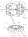
- a spring brake actuator 1 is shown.
- the spring brake actuator 1 comprises a spring brake portion 3 and a service brake portion 5.
- a housing part 7 which comprises a side wall 9 and a housing base 11.
- a spring seat 13 is provided on the housing base 11.
- the spring brake portion 3 comprises inside the housing part 7 a spring brake piston 15 which is shown in a retracted position and which is configured to reciprocating move between the shown retracted position and an extended position in the direction of a stroke axis Y, which is towards the right in Fig. 1a .
- the spring brake piston 15 is operatively coupled to a release mechanism 17.
- a spring assembly 20 is mounted inside the housing part 7 and is operatively coupled in between the spring seat 13 and the spring brake piston 15.
- the spring assembly 20 is configured to store potential energy in a loaded state, which is presently shown Fig. 1a , and to release and transform the potential energy stored in the spring when moving the spring brake piston 15 towards its extended position. This may be for example accomplished by releasing pressure from a pressure chamber 18.
- the necessary pressure lines and conduits are generally known and omitted from the figures to increase clarity with respect to the invention at hand.
- the spring brake piston 15 Upon release of pressure in the pressure chamber 18, the spring brake piston 15 acts against a diaphragm 19 and moves a piston extension against a push rod 29, which is located in the service brake portion 5.
- the push rod 29 of the service brake portion 5 is housed in a service housing part 23.
- a side wall 25 of the service brake portion 5 is mounted together with a second diaphragm 27 to a central flange portion 21.
- the first diaphragm 19 and the spring brake housing part 7 are mounted.
- a return spring 33 is configured to restore the push rod 29 towards its retracted position (shown in Fig. 1a ), and a bellows 31 protects the push rod 29 from ingress of dirt etc.
- the spring assembly 21 has an axis of action X which is allied in parallel, preferably coaxially, to the stroke direction Y of the spring brake actuator 1.
- the spring assembly 20 comprises at least one disc spring 100.
- the disc spring 100 comprises a shell 101 which extends from a radial outer periphery 102 towards a radial inner periphery 103.
- the shell 101 comprises a frusto-conically portion 109 and, adjacent thereto, a substantially planar portion 111 which extends in a plane perpendicular to the axis of action X.
- the radial inner periphery 103 comprises a protrusion 113 which acts as a mounting a positioning interface against the spring brake piston 15, cf. Fig. 1a .
- the disc spring 100 might in principle also be shaped as a Belleville spring, it may be beneficial for easier deformation to provide a plurality of serrations 105, which extend from one periphery, in the given example from the inner periphery 103, partially towards the opposite periphery, in this case the outer periphery 101.
- the serrations 105 form a plurality of spring tongues 107 each of which preferably is individually deformable to allow for better contact and action against the spring brake piston 15.
- the spring tongues 107 are integrally formed on or joined to a ring section 108 at the outer peripheral section 101 of the disc spring 100.
- the spring tongues 107 might be formed integrally to in inner ring section at the inner periphery 103 and extend outwardly toward the outer periphery 101.
- the spring assembly 20 comprises exactly one disc spring 100. It is however easily understood that the number of disc springs 100 may be increased as is required in view of spring travel and spring force. A plurality of spring discs might for example be stacked, or several stacks might be grouped together in X- or O-configuration.
- the spring assembly 20 having one or more disc springs 100 achieves a significant reduction in build size in the direction of the stroke axis Y as compared to conventional compression springs.
- spring assemblies comprising or consisting of disc springs can store efficient spring loads as potential energy without adverse effect on the function principal of the spring brake actuator 1 as a whole.
Landscapes
- Engineering & Computer Science (AREA)
- Transportation (AREA)
- Mechanical Engineering (AREA)
- Braking Arrangements (AREA)
Description
- The invention relates to a spring brake actuator for use in a vehicle, in particular in a commercial vehicle, the spring brake actuator comprising a housing part having a housing part having a housing base, a piston that is located inside the housing and configured to move along a stroke axis from a retracted position towards an extended position such as to transmit a brake force, and a spring assembly mounted between the housing base and the piston, wherein in the spring assembly comprises an axis of action, preferably aligned in parallel to the stroke axis and is operatively coupled to the piston such as to store potential energy and the piston is in the retracted position and to move the piston towards the extended position by transforming potential energy into kinetic energy.
- Spring brake actuators of the aforementioned type are widely known in the industry. Typically, the aforementioned housing part is also referred to as a spring brake portion, and the core functionality of the spring assembly is to generate a parking or emergency brake function which is transmitted by the piston onwards to a brake mechanism. Typically, these spring brake actuators additionally comprise a service brake portion which interacts with the spring brake piston of the spring brake portion and comprises a push rod which is operatively coupled to the brake mechanism.
- Typically, the spring assembly in the spring brake portion of a spring brake actuator is held in a loaded state by pressurizing a spring brake chamber which is delimited in part by either the spring piston itself or a diaphragm which abuts against the piston. If pressure is released from the spring brake chamber, the spring assembly is allowed to release from its loaded state and move the piston from the retracted position towards its extended position. Depending on the suddenness of the pressure release, the expansion movement of the spring and thus the movement of the piston can be very rapid. Rapid movement is essential in order to provide the required suddenness of reaction for emergency functions. At the same time, considerable amounts of potential energy need to be stored by the spring assembly in order to provide sufficient suddenness of movement over the required stroke length. One exemplary commercial example for the aforementioned spring brake actuator would be the so-called Tri-Stop brake actuators of the applicant.
- While the working principle of the aforementioned spring brake actuators is very reliable and satisfies safety needs, the ever-increasing complexity of vehicle systems creates a demand for optimizing build size of vehicle components in general, and braking components in particular. A crucial factor for vehicle brake systems is the build side of a brake actuator in the direction of the stroke axis, i.e. the axis of action of the spring assembly.
-
EP 0 074 734 A2 discloses a spring brake actuator with a spring assembly inside the spring brake actuator, wherein the spring assembly comprises one disc spring. In view thereof, it was an object of the invention to provide a spring brake actuator which can provide the required braking functionality at improved i.e. reduced, space requirements. - The invention attains the aforementioned object by suggesting a spring brake actuator having the features of
claim 1. In particular, the invention suggests a spring brake actuator of the initially mentioned type, wherein the spring assembly comprises at least one disc spring. - The invention is based upon the realization that instead of conventional compression springs which have been used in spring assemblies before, either as conically, cylindrically or (bi-)convexly wound coil springs, a spring assembly having at least one disc spring would be suited to satisfy the need of generating considerable brake force. It has been found that the design needs of disc springs allow for space-saving installation inside the spring brake actuator and help to significantly reduce the overall size of the spring brake actuator in the direction of the axis of action. The deformation rate of a disc spring is not as linear as the deformation rate of a coil spring in general, but the inventors found out that linearity is not of utmost importance for providing the required braking functionality, such that a disc spring, or rather any given number of disc springs, may be employed in a spring actuator according to the invention without adverse effect.
- The functioning principle of the known spring brake actuators can be maintained: The spring brake piston is moved into the retracted position by applying pressure inside the housing part, thereby deforming the spring assembly with the at least one disc spring into a loaded position in which the energy use to deform the spring as stall as potential energy. Upon release of pressure inside the housing part, the potential energy stored in the spring assembly is released and transformed into kinetic energy by moving the spring brake piston towards the extended position.
- According to the invention, the disc spring comprises a base body having a shell. Wherein in the released state of the disc spring, the shell preferably comprises a frusto-conically shaped portion, said portion preferably defining an opening angle in a cross-sectional plane along the axis of action, wherein in the extended position of the piston, the opening angle is smaller than in the retracted position. The smaller the angle in the extended position of the piston, the stiffer the deformation behaviour of the disc spring will be. Additionally or alternatively, the shell preferably comprises a planar portion extending in a plane perpendicular to the axis of action, when in the released state of the disc spring. The planar portion of the disc spring helps to smooth out the overall stiffness of the disc spring and contributes to a softer initial deformation.
- Generally, the disc spring according to the invention may also be formed as a planar washer spring, or a frusto-conically shaped washer spring, also referred to as Belleville spring. However, the disc spring according to the invention may also be formed as a diaphragm spring. As such, the shell preferably comprises a plurality of serrations extending from one radial periphery of the shell partially towards the opposing radial periphery such as to define a plurality of spring tongues. The spring tongues may for example extend inwardly from an outer periphery of the shell, or may extend outwardly from an inner periphery of the shell. Preferentially, each spring tongue is elastically deformable individually such that a disc spring having a plurality of serrations maybe beneficial when actuating a piston which is allowed to tilt into the housing part to some degree.
- In a further preferred embodiment, the spring tongues are integrally formed on a peripheral ring section of the disc spring. As mentioned before, this might be either an inner or outer ring section of the disc spring of the shell. It would, however, be possible to form the disc spring of multiple parts, which are then assembled together. Forming the spring tongues integrally on a peripheral spring section allows for producing the disc spring from a singular piece of material.
- The invention has hereinabove been described with the spring assembly having "at least one" disc spring. In a preferred embodiment, in case larger spring forces are required, or if a larger stroke length needs to be bridged by the spring assembly, the spring assembly comprises a plurality of disc springs arranged adjacent to one another along the axis of action. Preferably, the plurality of disc spring comprises at least one group of springs arranged in a stack. A stack is herein understood to mean a set of springs that are arranged in parallel to one another. When a disc spring having a frusto-conically shape portion is used, this means that the frusto-conical portions within the stack are oriented in the same manner. This has the effect of increasing the stiffness of the spring assembly considerably, since the stacked springs act like coil springs arranged parallel to one another.
- Additionally or alternatively, the plurality of disc springs comprises a plurality of disc springs or stacks arranged to one another in X- or O-configuration. By orienting one disc spring (or stack) not parallel but oppositely to the adjacent spring (or stack), they either form an X with one another or an O. Doing so has the same effect as if a plurality of coil springs were arranged in series to one another and provides for a comparatively soft deformation behavior while achieving longer spring travel.
- In a preferred embodiment, the housing part of the spring brake actuator comprises a housing base and a spring seed provided at the housing base, wherein the spring seed is operatively coupled to the spring assembly, in particular to a disc spring of the spring assembly and effective to hold the spring assembly reliably in place in the loaded position.
- The invention has hereinabove been described with respect to the spring brake actuator itself. In a further aspect, the invention also relates to a use of a specific type of spring in a spring assembly of a brake actuator of a vehicle, in particular a commercial vehicle.
- The inventions achieves the same object in this aspect as the spring actuator of the first aspect by suggesting that a disc spring be used, such that a spring brake actuator in accordance of any one of the preferred embodiments described hereinabove is obtained.
- The benefits and preferred embodiments of the spring brake actuator of the first aspect are also benefits and preferred embodiments of the use of the second aspect and vice versa, so that reference is made to the description thereof hereinabove and hereinafter, in order to avoid unnecessary repetition.
- For a more complete understanding of the invention, the invention will now be described in more detail with reference to the accompanying drawings. The detailed description will illustrate and describe or is considered as a preferred embodiment of the invention. It should of course be understood that various modifications and changes in form or detail could readily be made without departing from the scope of the invention. It is therefore intended that the invention may not be limited to the exact form and detail shown and described herein, nor to anything less than the whole of the invention disclosed herein and disclaimed hereinafter. Further, the features described in the description, the drawings and the claims disclosing the invention may be essential for the invention considered alone or in combination. In particular, any reference signs in the claims shall not be construed as limiting the scope of the invention. The word "comprising" does not exclude other elements or steps. The wording "a" or "an" does not exclude a plurality.
- In brief, the figures to which reference will be made show:
- Fig. 1a
- shows a schematic cross-sectional side view of a spring brake actuator according to the invention and
- Fig. 1b
- shows a schematic 3D-dimensional view of a spring assembly for the actuator of
Fig. 1a . - In exemplary
Fig. 1a , aspring brake actuator 1 is shown. Thespring brake actuator 1 comprises aspring brake portion 3 and aservice brake portion 5. - In the
spring brake portion 3, ahousing part 7 is provided which comprises aside wall 9 and ahousing base 11. On thehousing base 11, aspring seat 13 is provided. Thespring brake portion 3 comprises inside the housing part 7 aspring brake piston 15 which is shown in a retracted position and which is configured to reciprocating move between the shown retracted position and an extended position in the direction of a stroke axis Y, which is towards the right inFig. 1a . - The
spring brake piston 15 is operatively coupled to arelease mechanism 17. Aspring assembly 20 is mounted inside thehousing part 7 and is operatively coupled in between thespring seat 13 and thespring brake piston 15. Thespring assembly 20 is configured to store potential energy in a loaded state, which is presently shownFig. 1a , and to release and transform the potential energy stored in the spring when moving thespring brake piston 15 towards its extended position. This may be for example accomplished by releasing pressure from apressure chamber 18. The necessary pressure lines and conduits are generally known and omitted from the figures to increase clarity with respect to the invention at hand. - Upon release of pressure in the
pressure chamber 18, thespring brake piston 15 acts against adiaphragm 19 and moves a piston extension against apush rod 29, which is located in theservice brake portion 5. Thepush rod 29 of theservice brake portion 5 is housed in aservice housing part 23. Aside wall 25 of theservice brake portion 5 is mounted together with asecond diaphragm 27 to acentral flange portion 21. On the other side of thatflange portion 21, thefirst diaphragm 19 and the springbrake housing part 7 are mounted. - In the
service brake portion 5, areturn spring 33 is configured to restore thepush rod 29 towards its retracted position (shown inFig. 1a ), and abellows 31 protects thepush rod 29 from ingress of dirt etc. - The
spring assembly 21 has an axis of action X which is allied in parallel, preferably coaxially, to the stroke direction Y of thespring brake actuator 1. - As can best be seen in
Fig. 1b , thespring assembly 20 comprises at least onedisc spring 100. In the shown embodiment, thedisc spring 100 comprises ashell 101 which extends from a radialouter periphery 102 towards a radialinner periphery 103. Theshell 101 comprises a frusto-conically portion 109 and, adjacent thereto, a substantiallyplanar portion 111 which extends in a plane perpendicular to the axis of action X. The radialinner periphery 103 comprises aprotrusion 113 which acts as a mounting a positioning interface against thespring brake piston 15, cf.Fig. 1a . - While the
disc spring 100 might in principle also be shaped as a Belleville spring, it may be beneficial for easier deformation to provide a plurality ofserrations 105, which extend from one periphery, in the given example from theinner periphery 103, partially towards the opposite periphery, in this case theouter periphery 101. Thus, theserrations 105 form a plurality ofspring tongues 107 each of which preferably is individually deformable to allow for better contact and action against thespring brake piston 15. - The
spring tongues 107 are integrally formed on or joined to aring section 108 at the outerperipheral section 101 of thedisc spring 100. - In an alternative embodiment which is not shown, it might be just the other way around: The
spring tongues 107 might be formed integrally to in inner ring section at theinner periphery 103 and extend outwardly toward theouter periphery 101. - In the embodiments shown, the
spring assembly 20 comprises exactly onedisc spring 100. It is however easily understood that the number of disc springs 100 may be increased as is required in view of spring travel and spring force. A plurality of spring discs might for example be stacked, or several stacks might be grouped together in X- or O-configuration. - At any rate, it is clear from the embodiments that the
spring assembly 20 having one or more disc springs 100 achieves a significant reduction in build size in the direction of the stroke axis Y as compared to conventional compression springs. At the same time, spring assemblies comprising or consisting of disc springs can store efficient spring loads as potential energy without adverse effect on the function principal of thespring brake actuator 1 as a whole. -
- 1
- spring brake actuator
- 3
- spring brake portion
- 5
- service brake portion
- 7
- housing part
- 9
- side wall
- 11
- housing base
- 13
- spring seat
- 15
- spring brake piston
- 17
- release mechanism
- 18
- pressure chamber
- 19
- diaphragm
- 20
- spring assembly
- 21
- central flange portion
- 23
- service housing part
- 25
- side wall
- 27
- diaphragm
- 29
- push rod
- 31
- bellows
- 33
- return spring
- 100
- disc spring
- 101
- shell
- 102
- outer periphery
- 103
- inner periphery
- 105
- serration
- 107
- spring tongues
- 108
- ring section
- 109
- frusto-conical portion
- 111
- planar portion
- 113
- protrusion
- X
- axis of action
- Y
- stroke axis
Claims (10)
- Spring brake actuator (1) for use in a vehicle, in particular in a commercial vehicle, the spring brake actuator comprising:- a housing part defined as service brake portion (3) having a housing base (11),- a spring brake piston (15) that is located inside the housing and configured to move along a stroke axis (y) from a retracted position towards an extended position such as to transmit a brake force, and- a spring assembly (20) mounted between the housing base (11) and the spring brake piston (15), wherein the spring assembly (20) comprises an axis of action (x), preferably aligned in parallel to the stroke axis (y), and is operatively coupled to the spring brake piston (15) such as to store potential energy when the spring brake piston (15) is in the retracted position, and to move the piston towards the extended position by transforming potential energy into kinetic energy,wherein the spring assembly (20) comprises at least one disc spring (100), characterized in that the disc spring (100) comprises a base body having a shell (101), when in the released state of the disc spring (100), comprises a frusto-conically shaped portion (109) defining an opening angle in a cross-sectional plane along the axis of action (x), wherein in the extended position of the piston, the opening angle is smaller than in the retracted position.
- The spring brake actuator (1) of claim 1, wherein the shell (101), when in the released state of the disc spring (100), comprises a planar portion (111) extending in a plane perpendicular to the axis of action (X).
- The spring brake actuator (1) of any one of claims 1 to 2, wherein the shell (101) comprises a plurality of serrations (105) extending from one radial periphery (102) of the shell (101) partially towards the opposing radial periphery (103) such as to define a plurality of spring tongues (107).
- The spring brake actuator (1) of claim 3, wherein the spring tongues (107) are integrally formed on a peripheral ring section (108) of the disc spring (100).
- The spring brake actuator (1) of any one of the preceding claims, wherein the spring assembly (20) comprises a plurality of disc springs (100) arranged adjacent to one another along the axis of action (X).
- The spring brake actuator (1) of claim 5, wherein the plurality of disc springs (100) comprises at least one group of springs arranged in a stack.
- The spring brake actuator (1) of claim 7, wherein the plurality of disc springs (100) comprises plurality of stacks arranged to one another in X- or O-configuration.
- The spring brake actuator (1) of any one of the preceding claims, Wherein the housing part (5) comprises a housing base (11) and a spring seat (13) provided at the housing base (11), wherein the spring seat (13) is operatively coupled to the spring assembly (20).
- The spring brake actuator (1) of any one of the preceding claims, Wherein the disc spring (100) is partially or completely made of sheet metal, in particular spring steel.
- A use of a disc spring (100) in a spring assembly of a brake actuator (1) of a vehicle, in particular a commercial vehicle, wherein the spring brake actuator (1) is a spring brake actuator according to any one of the preceding claims.
Priority Applications (1)
| Application Number | Priority Date | Filing Date | Title |
|---|---|---|---|
| EP21162513.2A EP4059792B1 (en) | 2021-03-15 | 2021-03-15 | Spring brake actuator for use in a vehicle, and use of a disc spring therein |
Applications Claiming Priority (1)
| Application Number | Priority Date | Filing Date | Title |
|---|---|---|---|
| EP21162513.2A EP4059792B1 (en) | 2021-03-15 | 2021-03-15 | Spring brake actuator for use in a vehicle, and use of a disc spring therein |
Publications (2)
| Publication Number | Publication Date |
|---|---|
| EP4059792A1 EP4059792A1 (en) | 2022-09-21 |
| EP4059792B1 true EP4059792B1 (en) | 2024-03-27 |
Family
ID=74874675
Family Applications (1)
| Application Number | Title | Priority Date | Filing Date |
|---|---|---|---|
| EP21162513.2A Active EP4059792B1 (en) | 2021-03-15 | 2021-03-15 | Spring brake actuator for use in a vehicle, and use of a disc spring therein |
Country Status (1)
| Country | Link |
|---|---|
| EP (1) | EP4059792B1 (en) |
Family Cites Families (3)
| Publication number | Priority date | Publication date | Assignee | Title |
|---|---|---|---|---|
| GB1328089A (en) * | 1969-10-30 | 1973-08-30 | Girling Ltd | Vehicle wheel brakes |
| DE3274673D1 (en) * | 1981-09-09 | 1987-01-22 | Bendix Ltd | Actuator for brakes or the like |
| US4552056A (en) * | 1984-12-24 | 1985-11-12 | Wabco Ltd. | Manual release and automatic reset arrangement for spring-applied/air-released brake |
-
2021
- 2021-03-15 EP EP21162513.2A patent/EP4059792B1/en active Active
Also Published As
| Publication number | Publication date |
|---|---|
| EP4059792A1 (en) | 2022-09-21 |
Similar Documents
| Publication | Publication Date | Title |
|---|---|---|
| EP2674640B1 (en) | Deflection spring pneumatic actuator | |
| JP7032156B2 (en) | Methods and devices that use springs to reduce clutch and brake drag | |
| CN107850151B (en) | Disc brakes for motor vehicles and their brake pad assemblies | |
| US10864897B2 (en) | Brake device for a hydraulic motor vehicle brake system | |
| KR102733866B1 (en) | Parking brake apparatus | |
| KR20120016579A (en) | Mechanical Actuator Cartridge for Vehicle Brake | |
| US10364890B2 (en) | Double cup-shaped piston for a disc brake | |
| EP4059792B1 (en) | Spring brake actuator for use in a vehicle, and use of a disc spring therein | |
| CN102597563B (en) | Operating device for operating the clutch device | |
| EP4069563B1 (en) | Spring brake actuator | |
| JP2004513817A (en) | Vacuum brake booster with mechanical emergency braking assistance | |
| CN115038622A (en) | Stroke simulator | |
| WO1997006349A1 (en) | Brake actuator with centering dome in service chamber | |
| US20040262113A1 (en) | Flexible pressing force transmission plate and method of manufacture | |
| JP2013130240A (en) | Tension spring unit | |
| CN117108659A (en) | Piston cover for brake actuator and brake actuator including corresponding piston cover | |
| US3807279A (en) | Servo motors | |
| CN107646000B (en) | Device for changing pedal resistance and brake system | |
| EP4023512B1 (en) | Stamped spring seat for use in spring brake actuator, and spring brake actuator for use in commercial vehicles | |
| US6851526B2 (en) | Actuator assembly | |
| US7743894B2 (en) | Brake actuator reinforcement and method of attaching same | |
| US7287457B1 (en) | Structure for retaining a piston assembly in position relative to a cylinder | |
| US7607524B2 (en) | Clutch cover assembly | |
| EP3992488A1 (en) | Pneumatic service brake actuator | |
| CN114286897A (en) | Concentric Pneumatic Clutch Actuator and Its Improvement |
Legal Events
| Date | Code | Title | Description |
|---|---|---|---|
| PUAI | Public reference made under article 153(3) epc to a published international application that has entered the european phase |
Free format text: ORIGINAL CODE: 0009012 |
|
| STAA | Information on the status of an ep patent application or granted ep patent |
Free format text: STATUS: THE APPLICATION HAS BEEN PUBLISHED |
|
| AK | Designated contracting states |
Kind code of ref document: A1 Designated state(s): AL AT BE BG CH CY CZ DE DK EE ES FI FR GB GR HR HU IE IS IT LI LT LU LV MC MK MT NL NO PL PT RO RS SE SI SK SM TR |
|
| STAA | Information on the status of an ep patent application or granted ep patent |
Free format text: STATUS: REQUEST FOR EXAMINATION WAS MADE |
|
| 17P | Request for examination filed |
Effective date: 20230321 |
|
| RBV | Designated contracting states (corrected) |
Designated state(s): AL AT BE BG CH CY CZ DE DK EE ES FI FR GB GR HR HU IE IS IT LI LT LU LV MC MK MT NL NO PL PT RO RS SE SI SK SM TR |
|
| GRAP | Despatch of communication of intention to grant a patent |
Free format text: ORIGINAL CODE: EPIDOSNIGR1 |
|
| STAA | Information on the status of an ep patent application or granted ep patent |
Free format text: STATUS: GRANT OF PATENT IS INTENDED |
|
| INTG | Intention to grant announced |
Effective date: 20231222 |
|
| RIN1 | Information on inventor provided before grant (corrected) |
Inventor name: TRELA, MARCIN |
|
| GRAS | Grant fee paid |
Free format text: ORIGINAL CODE: EPIDOSNIGR3 |
|
| GRAA | (expected) grant |
Free format text: ORIGINAL CODE: 0009210 |
|
| STAA | Information on the status of an ep patent application or granted ep patent |
Free format text: STATUS: THE PATENT HAS BEEN GRANTED |
|
| AK | Designated contracting states |
Kind code of ref document: B1 Designated state(s): AL AT BE BG CH CY CZ DE DK EE ES FI FR GB GR HR HU IE IS IT LI LT LU LV MC MK MT NL NO PL PT RO RS SE SI SK SM TR |
|
| REG | Reference to a national code |
Ref country code: GB Ref legal event code: FG4D |
|
| REG | Reference to a national code |
Ref country code: CH Ref legal event code: EP |
|
| REG | Reference to a national code |
Ref country code: DE Ref legal event code: R096 Ref document number: 602021010802 Country of ref document: DE |
|
| REG | Reference to a national code |
Ref country code: IE Ref legal event code: FG4D |
|
| PG25 | Lapsed in a contracting state [announced via postgrant information from national office to epo] |
Ref country code: LT Free format text: LAPSE BECAUSE OF FAILURE TO SUBMIT A TRANSLATION OF THE DESCRIPTION OR TO PAY THE FEE WITHIN THE PRESCRIBED TIME-LIMIT Effective date: 20240327 |
|
| REG | Reference to a national code |
Ref country code: LT Ref legal event code: MG9D |
|
| PG25 | Lapsed in a contracting state [announced via postgrant information from national office to epo] |
Ref country code: GR Free format text: LAPSE BECAUSE OF FAILURE TO SUBMIT A TRANSLATION OF THE DESCRIPTION OR TO PAY THE FEE WITHIN THE PRESCRIBED TIME-LIMIT Effective date: 20240628 |
|
| PG25 | Lapsed in a contracting state [announced via postgrant information from national office to epo] |
Ref country code: HR Free format text: LAPSE BECAUSE OF FAILURE TO SUBMIT A TRANSLATION OF THE DESCRIPTION OR TO PAY THE FEE WITHIN THE PRESCRIBED TIME-LIMIT Effective date: 20240327 Ref country code: RS Free format text: LAPSE BECAUSE OF FAILURE TO SUBMIT A TRANSLATION OF THE DESCRIPTION OR TO PAY THE FEE WITHIN THE PRESCRIBED TIME-LIMIT Effective date: 20240627 |
|
| PG25 | Lapsed in a contracting state [announced via postgrant information from national office to epo] |
Ref country code: RS Free format text: LAPSE BECAUSE OF FAILURE TO SUBMIT A TRANSLATION OF THE DESCRIPTION OR TO PAY THE FEE WITHIN THE PRESCRIBED TIME-LIMIT Effective date: 20240627 Ref country code: NO Free format text: LAPSE BECAUSE OF FAILURE TO SUBMIT A TRANSLATION OF THE DESCRIPTION OR TO PAY THE FEE WITHIN THE PRESCRIBED TIME-LIMIT Effective date: 20240627 Ref country code: LT Free format text: LAPSE BECAUSE OF FAILURE TO SUBMIT A TRANSLATION OF THE DESCRIPTION OR TO PAY THE FEE WITHIN THE PRESCRIBED TIME-LIMIT Effective date: 20240327 Ref country code: HR Free format text: LAPSE BECAUSE OF FAILURE TO SUBMIT A TRANSLATION OF THE DESCRIPTION OR TO PAY THE FEE WITHIN THE PRESCRIBED TIME-LIMIT Effective date: 20240327 Ref country code: GR Free format text: LAPSE BECAUSE OF FAILURE TO SUBMIT A TRANSLATION OF THE DESCRIPTION OR TO PAY THE FEE WITHIN THE PRESCRIBED TIME-LIMIT Effective date: 20240628 Ref country code: FI Free format text: LAPSE BECAUSE OF FAILURE TO SUBMIT A TRANSLATION OF THE DESCRIPTION OR TO PAY THE FEE WITHIN THE PRESCRIBED TIME-LIMIT Effective date: 20240327 Ref country code: BG Free format text: LAPSE BECAUSE OF FAILURE TO SUBMIT A TRANSLATION OF THE DESCRIPTION OR TO PAY THE FEE WITHIN THE PRESCRIBED TIME-LIMIT Effective date: 20240327 |
|
| REG | Reference to a national code |
Ref country code: NL Ref legal event code: MP Effective date: 20240327 |
|
| PG25 | Lapsed in a contracting state [announced via postgrant information from national office to epo] |
Ref country code: SE Free format text: LAPSE BECAUSE OF FAILURE TO SUBMIT A TRANSLATION OF THE DESCRIPTION OR TO PAY THE FEE WITHIN THE PRESCRIBED TIME-LIMIT Effective date: 20240327 Ref country code: LV Free format text: LAPSE BECAUSE OF FAILURE TO SUBMIT A TRANSLATION OF THE DESCRIPTION OR TO PAY THE FEE WITHIN THE PRESCRIBED TIME-LIMIT Effective date: 20240327 |
|
| PG25 | Lapsed in a contracting state [announced via postgrant information from national office to epo] |
Ref country code: NL Free format text: LAPSE BECAUSE OF FAILURE TO SUBMIT A TRANSLATION OF THE DESCRIPTION OR TO PAY THE FEE WITHIN THE PRESCRIBED TIME-LIMIT Effective date: 20240327 |
|
| REG | Reference to a national code |
Ref country code: AT Ref legal event code: MK05 Ref document number: 1669633 Country of ref document: AT Kind code of ref document: T Effective date: 20240327 |
|
| PG25 | Lapsed in a contracting state [announced via postgrant information from national office to epo] |
Ref country code: NL Free format text: LAPSE BECAUSE OF FAILURE TO SUBMIT A TRANSLATION OF THE DESCRIPTION OR TO PAY THE FEE WITHIN THE PRESCRIBED TIME-LIMIT Effective date: 20240327 |
|
| PG25 | Lapsed in a contracting state [announced via postgrant information from national office to epo] |
Ref country code: IS Free format text: LAPSE BECAUSE OF FAILURE TO SUBMIT A TRANSLATION OF THE DESCRIPTION OR TO PAY THE FEE WITHIN THE PRESCRIBED TIME-LIMIT Effective date: 20240727 |
|
| PG25 | Lapsed in a contracting state [announced via postgrant information from national office to epo] |
Ref country code: SM Free format text: LAPSE BECAUSE OF FAILURE TO SUBMIT A TRANSLATION OF THE DESCRIPTION OR TO PAY THE FEE WITHIN THE PRESCRIBED TIME-LIMIT Effective date: 20240327 Ref country code: PT Free format text: LAPSE BECAUSE OF FAILURE TO SUBMIT A TRANSLATION OF THE DESCRIPTION OR TO PAY THE FEE WITHIN THE PRESCRIBED TIME-LIMIT Effective date: 20240729 |
|
| PG25 | Lapsed in a contracting state [announced via postgrant information from national office to epo] |
Ref country code: ES Free format text: LAPSE BECAUSE OF FAILURE TO SUBMIT A TRANSLATION OF THE DESCRIPTION OR TO PAY THE FEE WITHIN THE PRESCRIBED TIME-LIMIT Effective date: 20240327 |
|
| PG25 | Lapsed in a contracting state [announced via postgrant information from national office to epo] |
Ref country code: EE Free format text: LAPSE BECAUSE OF FAILURE TO SUBMIT A TRANSLATION OF THE DESCRIPTION OR TO PAY THE FEE WITHIN THE PRESCRIBED TIME-LIMIT Effective date: 20240327 Ref country code: CZ Free format text: LAPSE BECAUSE OF FAILURE TO SUBMIT A TRANSLATION OF THE DESCRIPTION OR TO PAY THE FEE WITHIN THE PRESCRIBED TIME-LIMIT Effective date: 20240327 |
|
| PG25 | Lapsed in a contracting state [announced via postgrant information from national office to epo] |
Ref country code: AT Free format text: LAPSE BECAUSE OF FAILURE TO SUBMIT A TRANSLATION OF THE DESCRIPTION OR TO PAY THE FEE WITHIN THE PRESCRIBED TIME-LIMIT Effective date: 20240327 |
|
| PG25 | Lapsed in a contracting state [announced via postgrant information from national office to epo] |
Ref country code: PL Free format text: LAPSE BECAUSE OF FAILURE TO SUBMIT A TRANSLATION OF THE DESCRIPTION OR TO PAY THE FEE WITHIN THE PRESCRIBED TIME-LIMIT Effective date: 20240327 |
|
| PG25 | Lapsed in a contracting state [announced via postgrant information from national office to epo] |
Ref country code: SK Free format text: LAPSE BECAUSE OF FAILURE TO SUBMIT A TRANSLATION OF THE DESCRIPTION OR TO PAY THE FEE WITHIN THE PRESCRIBED TIME-LIMIT Effective date: 20240327 |
|
| PG25 | Lapsed in a contracting state [announced via postgrant information from national office to epo] |
Ref country code: SM Free format text: LAPSE BECAUSE OF FAILURE TO SUBMIT A TRANSLATION OF THE DESCRIPTION OR TO PAY THE FEE WITHIN THE PRESCRIBED TIME-LIMIT Effective date: 20240327 Ref country code: SK Free format text: LAPSE BECAUSE OF FAILURE TO SUBMIT A TRANSLATION OF THE DESCRIPTION OR TO PAY THE FEE WITHIN THE PRESCRIBED TIME-LIMIT Effective date: 20240327 Ref country code: RO Free format text: LAPSE BECAUSE OF FAILURE TO SUBMIT A TRANSLATION OF THE DESCRIPTION OR TO PAY THE FEE WITHIN THE PRESCRIBED TIME-LIMIT Effective date: 20240327 Ref country code: PT Free format text: LAPSE BECAUSE OF FAILURE TO SUBMIT A TRANSLATION OF THE DESCRIPTION OR TO PAY THE FEE WITHIN THE PRESCRIBED TIME-LIMIT Effective date: 20240729 Ref country code: PL Free format text: LAPSE BECAUSE OF FAILURE TO SUBMIT A TRANSLATION OF THE DESCRIPTION OR TO PAY THE FEE WITHIN THE PRESCRIBED TIME-LIMIT Effective date: 20240327 Ref country code: IS Free format text: LAPSE BECAUSE OF FAILURE TO SUBMIT A TRANSLATION OF THE DESCRIPTION OR TO PAY THE FEE WITHIN THE PRESCRIBED TIME-LIMIT Effective date: 20240727 Ref country code: ES Free format text: LAPSE BECAUSE OF FAILURE TO SUBMIT A TRANSLATION OF THE DESCRIPTION OR TO PAY THE FEE WITHIN THE PRESCRIBED TIME-LIMIT Effective date: 20240327 Ref country code: EE Free format text: LAPSE BECAUSE OF FAILURE TO SUBMIT A TRANSLATION OF THE DESCRIPTION OR TO PAY THE FEE WITHIN THE PRESCRIBED TIME-LIMIT Effective date: 20240327 Ref country code: CZ Free format text: LAPSE BECAUSE OF FAILURE TO SUBMIT A TRANSLATION OF THE DESCRIPTION OR TO PAY THE FEE WITHIN THE PRESCRIBED TIME-LIMIT Effective date: 20240327 Ref country code: AT Free format text: LAPSE BECAUSE OF FAILURE TO SUBMIT A TRANSLATION OF THE DESCRIPTION OR TO PAY THE FEE WITHIN THE PRESCRIBED TIME-LIMIT Effective date: 20240327 |
|
| PG25 | Lapsed in a contracting state [announced via postgrant information from national office to epo] |
Ref country code: IT Free format text: LAPSE BECAUSE OF FAILURE TO SUBMIT A TRANSLATION OF THE DESCRIPTION OR TO PAY THE FEE WITHIN THE PRESCRIBED TIME-LIMIT Effective date: 20240327 |
|
| PG25 | Lapsed in a contracting state [announced via postgrant information from national office to epo] |
Ref country code: IT Free format text: LAPSE BECAUSE OF FAILURE TO SUBMIT A TRANSLATION OF THE DESCRIPTION OR TO PAY THE FEE WITHIN THE PRESCRIBED TIME-LIMIT Effective date: 20240327 |
|
| REG | Reference to a national code |
Ref country code: DE Ref legal event code: R097 Ref document number: 602021010802 Country of ref document: DE |
|
| PG25 | Lapsed in a contracting state [announced via postgrant information from national office to epo] |
Ref country code: DK Free format text: LAPSE BECAUSE OF FAILURE TO SUBMIT A TRANSLATION OF THE DESCRIPTION OR TO PAY THE FEE WITHIN THE PRESCRIBED TIME-LIMIT Effective date: 20240327 |
|
| PG25 | Lapsed in a contracting state [announced via postgrant information from national office to epo] |
Ref country code: DK Free format text: LAPSE BECAUSE OF FAILURE TO SUBMIT A TRANSLATION OF THE DESCRIPTION OR TO PAY THE FEE WITHIN THE PRESCRIBED TIME-LIMIT Effective date: 20240327 |
|
| PLBE | No opposition filed within time limit |
Free format text: ORIGINAL CODE: 0009261 |
|
| STAA | Information on the status of an ep patent application or granted ep patent |
Free format text: STATUS: NO OPPOSITION FILED WITHIN TIME LIMIT |
|
| 26N | No opposition filed |
Effective date: 20250103 |
|
| PG25 | Lapsed in a contracting state [announced via postgrant information from national office to epo] |
Ref country code: SI Free format text: LAPSE BECAUSE OF FAILURE TO SUBMIT A TRANSLATION OF THE DESCRIPTION OR TO PAY THE FEE WITHIN THE PRESCRIBED TIME-LIMIT Effective date: 20240327 |
|
| REG | Reference to a national code |
Ref country code: DE Ref legal event code: R119 Ref document number: 602021010802 Country of ref document: DE |
|
| PG25 | Lapsed in a contracting state [announced via postgrant information from national office to epo] |
Ref country code: MC Free format text: LAPSE BECAUSE OF FAILURE TO SUBMIT A TRANSLATION OF THE DESCRIPTION OR TO PAY THE FEE WITHIN THE PRESCRIBED TIME-LIMIT Effective date: 20240327 |
|
| REG | Reference to a national code |
Ref country code: CH Ref legal event code: H13 Free format text: ST27 STATUS EVENT CODE: U-0-0-H10-H13 (AS PROVIDED BY THE NATIONAL OFFICE) Effective date: 20251023 |
|
| PG25 | Lapsed in a contracting state [announced via postgrant information from national office to epo] |
Ref country code: LU Free format text: LAPSE BECAUSE OF NON-PAYMENT OF DUE FEES Effective date: 20250315 |
|
| GBPC | Gb: european patent ceased through non-payment of renewal fee |
Effective date: 20250315 |
|
| REG | Reference to a national code |
Ref country code: BE Ref legal event code: MM Effective date: 20250331 |
|
| PG25 | Lapsed in a contracting state [announced via postgrant information from national office to epo] |
Ref country code: DE Free format text: LAPSE BECAUSE OF NON-PAYMENT OF DUE FEES Effective date: 20251001 |
|
| PG25 | Lapsed in a contracting state [announced via postgrant information from national office to epo] |
Ref country code: GB Free format text: LAPSE BECAUSE OF NON-PAYMENT OF DUE FEES Effective date: 20250315 |
|
| PG25 | Lapsed in a contracting state [announced via postgrant information from national office to epo] |
Ref country code: FR Free format text: LAPSE BECAUSE OF NON-PAYMENT OF DUE FEES Effective date: 20250331 |
|
| PG25 | Lapsed in a contracting state [announced via postgrant information from national office to epo] |
Ref country code: BE Free format text: LAPSE BECAUSE OF NON-PAYMENT OF DUE FEES Effective date: 20250331 |
|
| PG25 | Lapsed in a contracting state [announced via postgrant information from national office to epo] |
Ref country code: CH Free format text: LAPSE BECAUSE OF NON-PAYMENT OF DUE FEES Effective date: 20250331 |
|
| PG25 | Lapsed in a contracting state [announced via postgrant information from national office to epo] |
Ref country code: IE Free format text: LAPSE BECAUSE OF NON-PAYMENT OF DUE FEES Effective date: 20250315 |