EP4059776B1 - Adaptive vehicle headlight - Google Patents
Adaptive vehicle headlight Download PDFInfo
- Publication number
- EP4059776B1 EP4059776B1 EP22162804.3A EP22162804A EP4059776B1 EP 4059776 B1 EP4059776 B1 EP 4059776B1 EP 22162804 A EP22162804 A EP 22162804A EP 4059776 B1 EP4059776 B1 EP 4059776B1
- Authority
- EP
- European Patent Office
- Prior art keywords
- light
- emitting unit
- light emitting
- rotating member
- frame portion
- Prior art date
- Legal status (The legal status is an assumption and is not a legal conclusion. Google has not performed a legal analysis and makes no representation as to the accuracy of the status listed.)
- Active
Links
Images


Classifications
-
- B—PERFORMING OPERATIONS; TRANSPORTING
- B60—VEHICLES IN GENERAL
- B60Q—ARRANGEMENT OF SIGNALLING OR LIGHTING DEVICES, THE MOUNTING OR SUPPORTING THEREOF OR CIRCUITS THEREFOR, FOR VEHICLES IN GENERAL
- B60Q1/00—Arrangement of optical signalling or lighting devices, the mounting or supporting thereof or circuits therefor
- B60Q1/02—Arrangement of optical signalling or lighting devices, the mounting or supporting thereof or circuits therefor the devices being primarily intended to illuminate the way ahead or to illuminate other areas of way or environments
- B60Q1/04—Arrangement of optical signalling or lighting devices, the mounting or supporting thereof or circuits therefor the devices being primarily intended to illuminate the way ahead or to illuminate other areas of way or environments the devices being headlights
- B60Q1/06—Arrangement of optical signalling or lighting devices, the mounting or supporting thereof or circuits therefor the devices being primarily intended to illuminate the way ahead or to illuminate other areas of way or environments the devices being headlights adjustable, e.g. remotely-controlled from inside vehicle
- B60Q1/08—Arrangement of optical signalling or lighting devices, the mounting or supporting thereof or circuits therefor the devices being primarily intended to illuminate the way ahead or to illuminate other areas of way or environments the devices being headlights adjustable, e.g. remotely-controlled from inside vehicle automatically
- B60Q1/12—Arrangement of optical signalling or lighting devices, the mounting or supporting thereof or circuits therefor the devices being primarily intended to illuminate the way ahead or to illuminate other areas of way or environments the devices being headlights adjustable, e.g. remotely-controlled from inside vehicle automatically due to steering position
- B60Q1/122—Arrangement of optical signalling or lighting devices, the mounting or supporting thereof or circuits therefor the devices being primarily intended to illuminate the way ahead or to illuminate other areas of way or environments the devices being headlights adjustable, e.g. remotely-controlled from inside vehicle automatically due to steering position with electrical actuating means
-
- B—PERFORMING OPERATIONS; TRANSPORTING
- B60—VEHICLES IN GENERAL
- B60Q—ARRANGEMENT OF SIGNALLING OR LIGHTING DEVICES, THE MOUNTING OR SUPPORTING THEREOF OR CIRCUITS THEREFOR, FOR VEHICLES IN GENERAL
- B60Q1/00—Arrangement of optical signalling or lighting devices, the mounting or supporting thereof or circuits therefor
- B60Q1/02—Arrangement of optical signalling or lighting devices, the mounting or supporting thereof or circuits therefor the devices being primarily intended to illuminate the way ahead or to illuminate other areas of way or environments
- B60Q1/04—Arrangement of optical signalling or lighting devices, the mounting or supporting thereof or circuits therefor the devices being primarily intended to illuminate the way ahead or to illuminate other areas of way or environments the devices being headlights
- B60Q1/06—Arrangement of optical signalling or lighting devices, the mounting or supporting thereof or circuits therefor the devices being primarily intended to illuminate the way ahead or to illuminate other areas of way or environments the devices being headlights adjustable, e.g. remotely-controlled from inside vehicle
- B60Q1/08—Arrangement of optical signalling or lighting devices, the mounting or supporting thereof or circuits therefor the devices being primarily intended to illuminate the way ahead or to illuminate other areas of way or environments the devices being headlights adjustable, e.g. remotely-controlled from inside vehicle automatically
- B60Q1/12—Arrangement of optical signalling or lighting devices, the mounting or supporting thereof or circuits therefor the devices being primarily intended to illuminate the way ahead or to illuminate other areas of way or environments the devices being headlights adjustable, e.g. remotely-controlled from inside vehicle automatically due to steering position
- B60Q1/124—Arrangement of optical signalling or lighting devices, the mounting or supporting thereof or circuits therefor the devices being primarily intended to illuminate the way ahead or to illuminate other areas of way or environments the devices being headlights adjustable, e.g. remotely-controlled from inside vehicle automatically due to steering position by mechanical means
-
- B—PERFORMING OPERATIONS; TRANSPORTING
- B62—LAND VEHICLES FOR TRAVELLING OTHERWISE THAN ON RAILS
- B62J—CYCLE SADDLES OR SEATS; AUXILIARY DEVICES OR ACCESSORIES SPECIALLY ADAPTED TO CYCLES AND NOT OTHERWISE PROVIDED FOR, e.g. ARTICLE CARRIERS OR CYCLE PROTECTORS
- B62J6/00—Arrangement of optical signalling or lighting devices on cycles; Mounting or supporting thereof; Circuits therefor
- B62J6/02—Headlights
- B62J6/022—Headlights specially adapted for motorcycles or the like
- B62J6/023—Headlights specially adapted for motorcycles or the like responsive to the lean angle of the cycle, e.g. changing intensity or switching sub-lights when cornering
-
- B—PERFORMING OPERATIONS; TRANSPORTING
- B62—LAND VEHICLES FOR TRAVELLING OTHERWISE THAN ON RAILS
- B62J—CYCLE SADDLES OR SEATS; AUXILIARY DEVICES OR ACCESSORIES SPECIALLY ADAPTED TO CYCLES AND NOT OTHERWISE PROVIDED FOR, e.g. ARTICLE CARRIERS OR CYCLE PROTECTORS
- B62J6/00—Arrangement of optical signalling or lighting devices on cycles; Mounting or supporting thereof; Circuits therefor
- B62J6/02—Headlights
- B62J6/022—Headlights specially adapted for motorcycles or the like
- B62J6/024—Switching between high and low beam
-
- B—PERFORMING OPERATIONS; TRANSPORTING
- B62—LAND VEHICLES FOR TRAVELLING OTHERWISE THAN ON RAILS
- B62J—CYCLE SADDLES OR SEATS; AUXILIARY DEVICES OR ACCESSORIES SPECIALLY ADAPTED TO CYCLES AND NOT OTHERWISE PROVIDED FOR, e.g. ARTICLE CARRIERS OR CYCLE PROTECTORS
- B62J6/00—Arrangement of optical signalling or lighting devices on cycles; Mounting or supporting thereof; Circuits therefor
- B62J6/02—Headlights
- B62J6/022—Headlights specially adapted for motorcycles or the like
- B62J6/026—Headlights specially adapted for motorcycles or the like characterised by the structure, e.g. casings
-
- F—MECHANICAL ENGINEERING; LIGHTING; HEATING; WEAPONS; BLASTING
- F21—LIGHTING
- F21S—NON-PORTABLE LIGHTING DEVICES; SYSTEMS THEREOF; VEHICLE LIGHTING DEVICES SPECIALLY ADAPTED FOR VEHICLE EXTERIORS
- F21S41/00—Illuminating devices specially adapted for vehicle exteriors, e.g. headlamps
- F21S41/60—Illuminating devices specially adapted for vehicle exteriors, e.g. headlamps characterised by a variable light distribution
- F21S41/68—Illuminating devices specially adapted for vehicle exteriors, e.g. headlamps characterised by a variable light distribution by acting on screens
- F21S41/683—Illuminating devices specially adapted for vehicle exteriors, e.g. headlamps characterised by a variable light distribution by acting on screens by moving screens
- F21S41/686—Blades, i.e. screens moving in a vertical plane
-
- B—PERFORMING OPERATIONS; TRANSPORTING
- B60—VEHICLES IN GENERAL
- B60Q—ARRANGEMENT OF SIGNALLING OR LIGHTING DEVICES, THE MOUNTING OR SUPPORTING THEREOF OR CIRCUITS THEREFOR, FOR VEHICLES IN GENERAL
- B60Q2300/00—Indexing codes for automatically adjustable headlamps or automatically dimmable headlamps
- B60Q2300/10—Indexing codes relating to particular vehicle conditions
- B60Q2300/13—Attitude of the vehicle body
- B60Q2300/136—Roll
-
- F—MECHANICAL ENGINEERING; LIGHTING; HEATING; WEAPONS; BLASTING
- F21—LIGHTING
- F21W—INDEXING SCHEME ASSOCIATED WITH SUBCLASSES F21K, F21L, F21S and F21V, RELATING TO USES OR APPLICATIONS OF LIGHTING DEVICES OR SYSTEMS
- F21W2107/00—Use or application of lighting devices on or in particular types of vehicles
- F21W2107/10—Use or application of lighting devices on or in particular types of vehicles for land vehicles
- F21W2107/13—Use or application of lighting devices on or in particular types of vehicles for land vehicles for cycles
- F21W2107/17—Use or application of lighting devices on or in particular types of vehicles for land vehicles for cycles for motorcycles
Definitions
- the present invention relates to a vehicle headlight, and more particularly to an adaptive vehicle headlight, which can provide auxiliary illumination for curved roads and is suitable for two-wheeled vehicles such as motorcycles and bicycles.
- IT MI20131056 A1 discloses a headlamp for use on a motor vehicle, which includes a body, a lens, a support element, at least one device, and a control unit.
- the body is fixed to a frame of the motor vehicle and contains at least one light source which emits light in a longitudinal direction.
- the lens is adapted to concentrate the light emitted by at least one light source according to a direction suitable for the projection of a dipped beam.
- the support element is integrated with the lens and equipped with at least one element for coupling to a rotation drive unit.
- the at least one device is configured for detecting the angle and the direction of inclination of the motor vehicle with respect to a plane on which the vehicle moves.
- the control unit emits group control signals as a function of at least one signal received by the at least one device.
- the headlight (headlamp), referred to by some as the "eyes" of a vehicle such as a motorcycle or a car, is very important to traffic safety.
- an illumination pattern provided by each of low and high beams in the headlight has a fixed orientation and cannot be adjusted to adapt to a tilt angle of a vehicle body. This may cause many inadequacies in actual use. For example, when the vehicle is running on a curved road, the illumination pattern in front of the vehicle would be tilted to the right or left. As a result, there is a blind area of vision present in front of the vehicle, so that the driver is unable to clearly see road conditions at an inside of the curved road and this may cause a traffic accident.
- headlights with an adjustable lighting pattern appear on the market.
- Such headlights can adjust characteristics of the lighting pattern according to a tilt angle of a vehicle body, such as a lighting range and a lighting distance, so as to provide the driver with the best vision and ensure traffic safety.
- the arrangement of the fill lights may lead to the inability in the headlight to reduce volume.
- the present invention provides an adaptive vehicle headlight that is more reliable and durable according to independent claim 1.
- the dependent claims show further embodiments of claim 1.
- the present invention provides an adaptive vehicle headlight for use in a vehicle body.
- the adaptive vehicle headlight includes a light body, an optical lens, a driver, and a control unit.
- the light body includes a base, a rotating member, an optical lens and a light emitting unit.
- the base includes a carrying portion that has a first carrying surface.
- the rotating member is configured to rotate relative to the base and surrounds the carrying portion.
- the light emitting unit is disposed on the first carrying surface to emit an illumination light beam.
- the rotating member includes an outer frame portion, an inner frame portion, and a wall portion. The outer frame portion and the inner frame portion are spaced apart from each other.
- the wall portion is connected between the outer frame portion and the inner frame portion, and the carrying portion is exposed from the wall portion.
- the carrying portion has an accommodating groove.
- the optical lens is fixed to the outer frame portion to allow the illumination light beam to project outwardly so as to produce an illumination pattern.
- the optical lens has a light input surface and the first carrying surface is opposite to the light input surface, such that the illumination light beam is emitted towards the light input surface.
- the driver is arranged in the light body to drive the rotating member.
- the control unit is arranged in the light body to cause an operation of the driver according to a tilt angle of the vehicle body, such that the optical lens is driven by the rotating member to rotate a predetermined angle.
- the driver includes a coil structure and a magnetic body, and the coil structure and the magnetic body are disposed between the outer frame portion, the inner frame portion and the wall portion.
- the carrying portion has an accommodating groove, the inner frame portion and a bearing are jointly disposed in the accommodating groove, and the inner frame portion is supported by the bearing.
- the present invention provides an adaptive vehicle headlight for being installed on a vehicle body for use.
- the adaptive vehicle headlight includes a light body, an optical lens, a driver, and a control unit.
- the light body includes a base, a light emitting unit, a light guiding member, a rotating member, and a light distributing member.
- the light emitting unit and the light guiding member are arranged on the base, and the light emitting unit is configured to emit an illumination light beam toward the light guiding member.
- the rotating member is configured to rotate relative to the base.
- the light distributing member is connected as a whole to the rotating member.
- the light distributing member is arranged between the optical lens and the light emitting unit.
- the driver is arranged in the light body to drive the rotating member.
- the control unit is arranged in the light body to cause an operation of the driver according to a low beam mode and a high beam mode, such that the light distributing member is driven by the rotating member to move to a first position or a second position.
- the adaptive vehicle headlight provided by the present invention has the following beneficial effects:
- All illumination patterns as described herein can meet the light distribution requirements of the ECE R113 regulation which regulates headlamps for producing a symmetrical light pattern.
- a first embodiment of the present invention provides an adaptive vehicle headlight Z including a light body 1, an optical lens 2, a driver 3, and a control unit 4.
- the optical lens 2, the driver 3, and the control unit 4 are integrated into the light body 1, specific details of which will be described below. Accordingly, the optical lens 2, the driver 3, and the control unit 4 can be isolated from an external environment, and are not easily affected by external environmental factors such as water and dust.
- the adaptive vehicle headlight Z of the present invention is suitable for two-wheeled vehicles such as fuel motorcycles, electric motorcycles, general bicycles, and electric assisted bicycles.
- the adaptive vehicle headlight Z of the present invention can be installed on a vehicle body V to provide sufficient front illumination during a turn of a vehicle, so as to reduce or even eliminate blind area of vision in front of the vehicle, thereby improving traffic safety.
- the light body 1 includes a base 11, a rotating member 12, and a light emitting unit 13.
- the base 11 has a carrying portion 11a.
- the rotating member 12 is configured to rotate relative to the base 11.
- the light emitting unit 13 is arranged on the carrying portion 11a to emit an illumination light beam.
- the optical lens 2 is connected as a whole to the rotating member 12 for light distribution of the illumination light beam. That is, the illumination light beam is projected outwardly through the optical lens 2 to produce an illumination pattern having a cut-off line.
- the driver 3 is configured to drive the rotating member 12.
- the control unit 4 is configured to cause an operation of the driver 3 according to a tilt angle of the vehicle body V, such that the rotating member 12 synchronously rotates a predetermined angle with the optical lens 2.
- the base 11 is configured to divide an internal space of the light body 1 into a first space S1 and a second space S2.
- the carrying portion 11a, the rotating member 12, the light emitting unit 13, the optical lens 2, and the driver 13 are all located in the first space S1.
- the control unit 4 is located in the second space S2. More specifically, the carrying portion 11a has a first carrying surface 111.
- the first carrying surface 111 can be opposite to a light input surface 200 of the optical lens 2, and preferably opposite to and parallel to the light input surface 200 of the optical lens 2.
- the light emitting unit 13 is arranged on the first carrying surface 111 to emit the illumination light beam directly toward the light input surface 200 of the optical lens 2.
- the rotating member 12 is arranged to surround the carrying portion 11a, in which a rotation axis 34 coincides with a central axis of the carrying portion 11a.
- the driver 3 is arranged between the rotating member 12 and the carrying portion 11a, and can drive the rotating member 12 in a non-contact manner (e.g., applying a non-contact force), so as to allow the rotating member 12 to synchronously rotate with the optical lens 2.
- a non-contact manner e.g., applying a non-contact force
- the base 11 can further has a spacing portion 11b, and the internal space of the light body 1 can be divided into the first space S1 and the second space S2 by the spacing portion 11b.
- the carrying portion 11a can be formed to extend from the spacing portion 11b.
- the rotating member 12 can include an outer frame portion 12a, an inner frame portion 12b, and a wall portion 12c.
- the outer frame portion 12a and the inner frame portion 12b can be spaced apart from each other in an up-down direction.
- the wall portion 12c can be connected between the outer frame portion 12a and the inner frame portion 12b, and the first carrying surface 111 of the carrying portion 11a is exposed from the wall portion 12c.
- the optical lens 2 can be fixed to the outer frame portion 12a.
- the optical lens 2 can be an asymmetric optical lens, in which curvatures in the horizontal direction and the vertical direction are different from each other.
- the driver 3 can be a brushless pan/tilt motor and includes a coil structure 31 and a magnetic body 32.
- the coil structure 31 and the magnetic body 32 can be arranged between the outer frame portion 12a, the inner frame portion 12b, and the wall portion 12c and at a certain distance from each other.
- the coil structure 31 can be composed of iron cores with coils, and the magnetic body 32 can be formed from one or more magnets.
- the control unit 4 can include a control printed circuit board (PCB) and a tilt sensor (not shown), and at least has control functions of the light emitting unit 13 and the driver 3.
- PCB control printed circuit board
- an external structure 14 of the light body 1 includes a housing 14a, a light cover 14b, and a back lid 14c.
- the housing 14a has a first open end 141a and a second open end 142a opposite to the first open end 141, the shape of which is not limited to a cylindrical shape.
- the base 11 can be integrally formed inside the housing 14a.
- the light cover 14b is assembled to the first open end 141a of the housing 14a, and the light cover 14b, one portion (e.g., a front portion) of the housing 14a, and the base 11 jointly define the first space S1.
- the back lid 14c is assembled to the second open end 142a of the housing 14a, and the back lid 14c and a second portion (e.g., a rear portion) of the housing 14a jointly define the second space S2.
- the carrying portion 11a of the base 11 can have a first wire groove G2 for passing wire(s) outwardly from the light emitting unit 13.
- the spacing portion 11b of the base 11 can have a second wire groove G3 for passing wire(s) outwardly from the coil structure 31. Therefore, these wires cannot be interfered with mechanical parts, so that the headlight can work normally for a long period of time.
- control unit 4 can be arranged at the outside of the light body 1 and electrically connected to the light emitting unit 13 and the driver 3 (e.g., the coil structure 31 of the driver 3), as shown in FIG. 6B .
- the light cover 14b can be omitted for cost saving.
- the carrying portion 11a can have an accommodating groove G1, and a bearing B is disposed between the inner frame portion 12b and the carrying portion 11a.
- the inner frame portion 12b of the rotating member 12 and the bearing B can be jointly disposed in the accommodating groove G1, in which the inner frame portion 12b is supported by the bearing B.
- the carrying portion 11a can further have a second carrying surface 112 located outside of the accommodating groove G1 and perpendicular to the first carrying surface 111.
- the coil structure 31 can be fixed to the second carrying surface 112 of the carrying portion 11a, and the magnetic body 32 can be fixed to the outer frame portion 12a of the rotating member 12. Accordingly, the coil structure 31 and the magnetic body 32 can work with each other to produce an electromagnetic torque, thereby allowing the rotating member 12 to rotate in a clockwise or counterclockwise direction.
- the driver 3 includes a stator portion 3a and a rotor portion 3b.
- the stator portion 3a includes a coil structure 31.
- the rotor portion 3b includes a magnetic body 32 and is connected to the rotating member 12. Accordingly, when coils in the coil structure 31 are energized, the rotor portion 3b can drive the rotating member 12 to synchronously rotate with the optical lens 2.
- the driver 3 can be a stepper motor that is arranged in the second space S2 of the light body 1 and has a driving structure 33 (e.g., a driving shaft) extending from the second space S2 to the first space S1 to be transmittingly connected to rotating member 12.
- a front end of the driving structure 33 can be connected to the rotating member 12 via a gear set (not shown) that can be composed of a plurality of gears with different diameters. Accordingly, the driving structure 33 being rotated can drive the rotating member 12 to rotate on the carrying portion 11a by the gear set. That is, the rotational movement of the driving structure 33 can be converted into the rotational movement of the rotating member 12 by the gear set.
- the driver 3 can be arranged outside of the light body 1 and connected to the rotating member 12 located in the light body 1 via the driving structure 33, such that the rotating member 12 can be rotated to the left or right.
- the adaptive vehicle headlight Z of the present invention can provide sufficient front illumination for a vehicle (e.g., a two-wheeled vehicle) when driving, so as to reduce or even eliminate blind areas BA of vision in front of the vehicle.
- a vehicle e.g., a two-wheeled vehicle
- the detailed descriptions are as follows.
- a vehicle e.g., a two-wheeled vehicle
- an illumination pattern P produced by the adaptive vehicle headlight Z will be in a horizontal state, as shown in FIG. 10 . Therefore, no blind areas of vision are present in front of the vehicle, as shown in FIG. 15 .
- the optical lens 2 can be driven by the rotating member 2 to rotate left by a predetermined angle (i.e., rotate in a clockwise direction viewing from the driver), such that the illumination pattern P is still maintained in the horizontal state and there is a light distribution above the H-H line, as shown in FIG. 12 . Therefore, an auxiliary illumination zone IA can be produced to eliminate the blind area of vision at the front left of the vehicle, as shown in FIG. 17 .
- the optical lens 2 can be driven by the rotating member 2 to rotate right by a predetermined angle (i.e., rotate in a counterclockwise direction viewing from the driver), such that the illumination pattern P is still maintained in the horizontal state and there is a light distribution above the H-H line, as shown in FIG. 14 . Therefore, an auxiliary illumination zone IA can be produced to eliminate the blind area of vision at the front left of the vehicle, as shown in FIG. 19 .
- the light emitting unit 13 can include a first light emitting unit 13a and a second light emitting unit 13b, and can further include one or more wavelength converting layers (e.g., fluorescent layers, not shown in FIG. 20 ) covering the first light emitting unit 13a and the second light emitting unit 13b if necessary, so as to produce optical characteristics required for practical implementations.
- the light emitting unit 13 can be mounted on a circuit substrate, and it can be an LED package structure, but is not limited thereto.
- the first light emitting unit 13a and the second light emitting unit 13b are arranged in proximity to a lens focus 201, and the first light emitting unit 13a is arranged above the second light emitting unit 13b.
- the first light emitting unit 13a can include at least two first LED chips 131a.
- the second light emitting unit 13b can include at least one second LED chip 131b.
- An illumination light beam emitted from the first light emitting unit 13a that is lighted up can be projected outwardly through the optical lens 2 to produce a low beam illumination pattern.
- An illumination light beam emitted from the first light emitting unit 13a and the second light emitting unit 13b that are lighted up at the same time can be projected outwardly through the optical lens 2 to produce a high beam illumination pattern.
- the two first LED chips 131a can be arranged above the lens focus 201 and symmetrically distributed at left and right sides of a vertical symmetry plane 201s passing through the lens focus 201.
- the second light emitting unit 13b can be arranged at the lens focus 201.
- the two first LED chips 131a can be lighted up in a low beam mode
- the two first LED chips 131a and the second light emitting unit 13b can be lighted up in a high beam mode.
- all or the left one of the two first LED chips 131a can be lighted up in a low beam mode.
- a resulting illumination pattern P would have an amount of light spilling beyond the H-H line, i.e., a cut-off line CF of the resulting illumination pattern P would be located above the H-H line, as shown in FIG. 12 .
- the amount of light spilling would be eliminated, i.e., the cut-off line CF of the resulting illumination pattern P would be located below and close to the H-H line.
- the two first LED chips 131a and the second light emitting unit 13b can be lighted up, or the left one of the two first LED chips 131a and the second light emitting unit 13b can be lighted up.
- all or the right one of the two first LED chips 131a can be lighted up in a low beam mode.
- a resulting illumination pattern P would have an amount of light spilling beyond the H-H line, i.e., a cut-off line CF of the resulting illumination pattern P would be located above the H-H line, as shown in FIG. 14 .
- the amount of light spilling would be eliminated, i.e., the cut-off line CF of the resulting illumination pattern P would be located below and close to the H-H line.
- the two first LED chips 131a and the second light emitting unit 13b can be lighted up, or the right one of the two first LED chips 131a and the second light emitting unit 13b can be lighted up.
- the first light emitting unit 13a includes four first LED chips 131a and the second light emitting unit 13b includes two second LED chips 131b.
- the four first LED chips 131a can be arranged above the lens focus 201 and symmetrically distributed in pairs at left and right sides of a vertical symmetry plane 201s.
- the two second LED chips 131b correspond in position to the lens focus 201 and symmetrically distributed at left and right sides of the vertical symmetry plane 201s.
- the two second LED chips 131b are respectively aligned with the middle two of the four first LED chips 131a in the up-down direction.
- all or the middle two of the four first LED chips 131a can be lighted up in a low beam mode.
- the four first LED chips 131a and the two second LED chips 131b can be lighted up, or the middle two of the four first LED chips 131a and the two second LED chips 131b can be lighted up.
- all of the four first LED chips 131a can be lighted up, or the first one or two of the four first LED chips 131a located at the left side of the vertical symmetry plane 201s can be lighted up.
- a resulting illumination pattern P would have an amount of light spilling beyond the H-H line, i.e., a cut-off line CF of the resulting illumination pattern P would be located above the H-H line, as shown in FIG. 12 .
- the four first LED chips 131a and the two second LED chips 131b can be lighted up, or the first one or two of the four first LED chips 131a located at the left side of the vertical symmetry plane 201s and the two second LED chips 131b can be lighted up.
- all of the four first LED chips 131a can be lighted up, or the first one or two of the four first LED chips 131a located at the right side of the vertical symmetry plane 201s can be lighted up.
- a resulting illumination pattern P would have an amount of light spilling beyond the H-H line, i.e., a cut-off line CF of the resulting illumination pattern P would be located above the H-H line, as shown in FIG. 14 .
- the four first LED chips 131a and the two second LED chips 131b can be lighted up, or the first one or two of the four first LED chips 131a located at the right side of the vertical symmetry plane 201s and the two second LED chips 131b can be lighted up.
- two of the four first LED chips 131a located at the left or right side of the vertical symmetry plane 201s has a first spacing D1 therebetween.
- the middle two of the four first LED chips 131a has a second spacing D2 therebetween.
- the two second LED chips 131b has a third spacing D3 therebetween, and a fourth spacing D4 is present between each of the two second LED chips 131b and the corresponding one of the two second LED chips 131b.
- the first spacing D1, the second spacing D2, the third spacing D3, and the fourth spacing D4 satisfy the equations (1) to (4): 0 ⁇ First spacing D 1 ⁇ 1mm 0.01 mm ⁇ Second spacing D2 ⁇ 2mm 0 ⁇ Third spacing D3 ⁇ 1mm 0 ⁇ Fourth spacing D4 ⁇ 1mm
- the adaptive vehicle headlight Z which can include one or more first LED chips 131a.
- the first light emitting unit 13a can include four first LED chips 131a arranged to satisfy the equations (1) to (4).
- the adaptive vehicle headlight Z can only produce a low beam illumination pattern.
- a second embodiment of the present invention provides an adaptive vehicle headlight Z including a light body 1, an optical lens 2, a driver 3, and a control unit 4.
- the optical lens 2, the driver 3, and the control unit 4 are integrated into the light body 1.
- the light body 1 includes a base 11, a rotating member 12, and a light emitting unit 13.
- the base 11 has a carrying portion 11a.
- the rotating member 12 is configured to rotate relative to the base 11.
- the light emitting unit 13 is arranged on the carrying portion 11a to emit an illumination light beam.
- the optical lens 2 is connected as a whole to the rotating member 12 for light distribution of the illumination light beam.
- the illumination light beam is projected outwardly through the optical lens 2 to produce an illumination pattern having a cut-off line.
- the driver 3 is configured to drive the rotating member 12.
- the control unit 4 is configured to cause an operation of the driver 3 according to a tilt angle of a vehicle body V, such that the optical lens 2 can be driven by the rotating member 12 to rotate a predetermined angle.
- the necessary details of the light body 1, the optical lens 2, the driver 3, and the control unit 4 are described in the first embodiment, and will not be reiterated herein.
- the light body 1 further includes a light distributing member 15 arranged between the optical lens 2 and the light emitting unit 3.
- the light distributing member 15 can adjust the distribution of the illumination light beam, such that the illumination pattern can have a clearer cut-off line and contour. If the illumination pattern is a low beam illumination pattern, the cut-off line thereof is located below the H-H line (i.e., there is no light distribution above the H-H line).
- the light distributing member 15 can be a light shielding plate, a free end of which is not connected to other parts and has an optically effective edge (also called cut-off edge) to produce a different light distribution effect, but the present invention is not limited thereto.
- the light distributing member 15 is connected as a whole to the rotating member 12, such that it can be driven by the rotating member 12 to reciprocally move between a first position as shown in FIG. 26 and a second position as shown in FIG. 27 to selectively cover the light emitting unit 13. Accordingly, adaptive vehicle headlight Z can be switched between a low beam mode and a high beam mode. In the low beam mode, the light distributing member 15 is located at the first position. In the high beam mode, the light distributing member 15 is located at the second position.
- the rotating member 12 is driven in a non-contact manner.
- the driver 3 can be a brushless pan/tilt motor and includes a coil structure 31 and a magnetic body 32.
- the coil structure 31 and the magnetic body 32 can be arranged between an outer frame portion 12a, an inner frame portion 12b, and a wall portion 12c and at a certain distance from each other. Accordingly, the coil structure 31 and the magnetic body 32 can work with each other to produce an electromagnetic torque, thereby allowing the rotating member 12 to rotate in a clockwise or counterclockwise direction.
- the coil structure 31 can be composed of iron cores with coils, and the magnetic body 32 can be formed from one or more magnets, but the present invention is not limited thereto.
- the rotating member 12 is driven in a direct contact manner.
- the driver 3 can be a stepper motor and has a driving structure 33 (e.g., a driving shaft) transmittingly connected to rotating member 12 to provide driving force for rotation, thereby allowing the rotating member 12 to rotate in a clockwise or counterclockwise direction.
- the driving structure 33 can be connected to the rotating member 12 via a gear set (not shown in FIG. 24 and FIG. 25 ) that can be composed of a plurality of gears with different diameters, but the present invention is not limited thereto.
- the light emitting unit 13 can include a first light emitting unit 13a and a second light emitting unit 13b.
- the first light emitting unit 13a and the second light emitting unit 13b are arranged in proximity to a lens focus 201, and the first light emitting unit 13a is arranged above the second light emitting unit 13b. More details about the light-emitting unit 13 are provided in the first embodiment and FIG. 20 and FIG. 21 .
- the light distributing member 15 located at the first position covers the second light emitting unit 13b, as shown in FIG. 26 , such that a resulting illumination pattern is a low beam illumination pattern.
- the light distributing member 15 located at the second position allows the first light emitting unit 13a and the second light emitting unit 13b to be exposed therefrom, as shown in FIG. 27 , such that a resulting illumination pattern is a high beam illumination pattern.
- the arrangement of the light-emitting unit 13 is not limited to those shown in FIG. 20 and FIG. 21 .
- the light-emitting unit 13 can include one or more LED chips.
- the light distributing member 15 is fixed to the wall portion 12c and connected to the outer frame portion 12a of the rotating member 2 via a balancing member 16.
- the balancing member 16 can be a spring, but is not limited thereto. In use, in a low beam mode, the balancing member 16 is in an original state to lift up the light distributing member 15 to the first position. In a high beam mode, the balancing member 16 is in a compressed state to allow the light distributing member 15 to be guided to the second position.
- the carrying portion 11a of the base 11 can have a lifting structure 113 with a first guiding surface 1131.
- the light distributing member 15 can have a guiding structure 152 with a second guiding surface 1521.
- Each of the first guiding surface 1131 and the second guiding surface 1521 can be an arc surface. Accordingly, the light distributing member 15 can be guided by the guiding structure 152 and lifted up to the second position by the lifting structure 113. That is, the light distributing member 15 is lifted up to the second position by the slidable cooperation of the second guiding surface 1521 of the guiding structure 152 with the first guiding surface 1131 of the lifting structure 113.
- FIG. 27 to FIG. 29 shows that the light distributing member 15 is moved up by a contact force produced between the light distributing member 15 and the carrying portion 11a of the base 11, in practice, the light distributing member 15 can be moved up by a non-contact force produced between the light distributing member 15 and the carrying portion 11a of the base 11.
- magnetic components can be arranged between the light distributing member 15 and the carrying portion 11a of the base 11. The magnetic components can produce a magnetic force such as a magnetic attraction force to raise the light distributing member 15 to a predetermined height, or produce another magnetic force such as a magnetic repulsion force to lower the light distributing member 15 to an initial height.
- a limiting member 17 can be arranged between the light distributing member 15 and the outer frame portion 12a of the rotating member 12 to limit the balancing member 16 (e.g., a horizontal movement of the balancing member 16).
- the limiting member 17 can be a limiting pin, but is not limited thereto. More specifically, the light distribution member 15 can have a pin hole 153 at the bottom thereof. The limiting member 17 can pass through the pin hole 153 and a distal end thereof can be inserted into and fixed in position to the outer frame portion 12a of the rotating member 12.
- the light emitting unit 13 has a light emitting surface 130, and the center point P of the light emitting surface 130 is flush with an optically effective edge 151 of the light distributing member 15. Furthermore, the light distributing member 15 has an inner surface 150 opposite to the light emitting surface 130, and a horizontal distance D5 between the inner surface 150 and the light emitting surface 130 satisfies: 0 mm ⁇ horizontal distance D5 ⁇ 1.0 mm.
- a third embodiment which does not fall within the present invention provides an adaptive vehicle headlight Z including a light body 1, an optical lens 2, a driver 3, and a control unit 4.
- the optical lens 2, the driver 3, and the control unit 4 are integrated into the light body 1.
- the light body 1 includes a base 11, a light emitting unit 13, a light guiding member 18, a rotating member 12, and a light distributing member 15.
- the light emitting unit 13 and the light guiding member 18 are arranged on the base 11, and the light emitting unit 13 is configured to emit an illumination light beam toward the light guiding member 18.
- the rotating member 12 is configured to rotate relative to the base 11.
- the light distributing member 15 is connected as a whole to the rotating member 12.
- the optical lens 2 is configured to project the illumination light beam outwardly so as to produce an illumination pattern having a cut-off line.
- the light distributing member 15 is arranged between the optical lens 2 and the light emitting unit 13.
- the driver 3 is configured to drive the rotating member 12.
- the control unit 4 is configured to cause an operation of the driver 3 according to a low beam mode and a high beam mode, such that the light distributing member 15 is driven by the rotating member 12 to move to a first position or a second position.
- the base 11 has a carrying surface 111' perpendicular to a light input surface 200 of the optical lens 2 and located below a lens optical axis 202.
- the light emitting unit 13 and the light guiding member 18 are arranged on the carrying surface 111', and the illumination light beam emitted from the light emitting unit 13 is guided by the light guiding member 18 and transmitted to the light input surface 200 of the optical lens 2 along a predetermined path.
- the rotating member 12 is connected to the driver 3, and the rotating member 12 and the driver 3 are each at a position avoiding the predetermined path along which the illumination light beam is transmitted.
- the light distributing member 15 located at the first position can shield a portion of the illumination light beam transmitted along the predetermined path, so as to produce a low beam illumination pattern.
- the light distributing member 15 located at the second position can allow all the illumination light beam transmitted along the predetermined path to enter the optical lens 2 through the light input surface 200, so as to produce a high beam illumination light pattern.
- the base 11 has a carrying portion 11a and a spacing portion 11b.
- the spacing portion 11b is configured to divide the internal space of the light body 1 into a first space S1 and a second space S2.
- the spacing portion 11b has an opening 114, and the first space S1 is in spatial communication with the second space S2 via the opening 114.
- the carrying portion 11a has the carrying surface 111'.
- the rotating member 12, the light distributing member 15, and the optical lens 2 are located in the first space S1.
- the driver 3 can be located the first space S1 or the second space S2.
- the definition of the light body 1, in which the internal space is divided into the first space S1 and the second space S2, is for ease of illustration of the positional relationship between the rotating member 12, the light emitting unit 13, and the light distributing member 15, the present invention is not limited thereto.
- the rotating member 12 and the light distributing member 15 can be located in the second space S2 and between the light emitting unit 13 and the optical lens 2. In such a structure, if the spacing portion 11b is closer to the light emitting unit 13, the rotating member 12 and the light distributing member 15 would be farther away from the light emitting unit 13. If the spacing portion 11b is farther away from the light emitting unit 13, the rotating member 12 and the light distributing member 15 would be closer to the light emitting unit 13.
- an external structure of the light body 1 includes a housing 14a and a light cover 14b.
- the housing 14a has an open end 140a and a closed end (not numbered), the shape of which is not limited to a cylindrical shape.
- the light cover 14b is assembled to the open end 140a of the housing 14a.
- the base 11 can be integrally formed inside the housing 14a.
- One portion (e.g., a front portion) of the housing 14a and the spacing portion 11b of the base 11 jointly define the first space S1
- a second portion e.g., a rear portion of the housing 14a and the spacing portion 11b of the base 11 jointly define the second space S2.
- another open end can be formed in place of the closed end of the housing 14a and is closed by a back lid.
- Other relevant details are provided in the first embodiment and FIG. 4 to FIG. 6 .
- the rotating member 12 is driven in a non-contact manner. More specifically, as shown in FIG. 31 and FIG. 32 , the driver 3 is arranged in the first space S1 of the light body 1.
- the driver 3 can be a brushless pan/tilt motor and includes a stator portion 3a and a rotor portion 3b.
- the stator portion 3a can be connected to the spacing portion 11b of the base 11, and the rotor portion 3b can rotate in a clockwise or counterclockwise direction about a rotation axis 34 by cooperating with the stator portion 3a.
- the rotation axis 34 can coincide with or be slightly offset from the lens optical axis 202.
- the stator portion 3a can include a coil structure (not shown in FIG.
- the rotor portion 3b can include a magnetic body (not shown in FIG. 31 and FIG. 32 ) that can be formed from one or more magnets.
- the rotating member 12 can be connected to the rotor portion 3b so as to synchronously rotate with the rotor portion 3b.
- the rotating member 12 is not limited to have a disc shape, and it is formed with a hollow area corresponding in position to the opening 114 of the spacing portion 11b.
- the rotating member 12 is driven in a direct contact manner. More specifically, as shown in FIG. 33 and FIG. 34 , the driver 3 is arranged in the second space S2 of the light body 1.
- the driver 3 can be a stepper motor and has a driving structure 33 (e.g., a driving shaft) transmittingly connected to rotating member 12 to provide driving force for rotation, thereby allowing the rotating member 12 to rotate in a clockwise or counterclockwise direction.
- the driving structure 33 can extend from the second space S2 to the first space S1 and be connected to the rotating member 12 via a gear set (not shown in FIG. 33 and FIG. 34 ) that can be composed of a plurality of gears with different diameters, but the present invention is not limited thereto.
- the control unit 4 can include a control printed circuit board (PCB) and at least has control functions of the light emitting unit 13 and the driver 3.
- PCB control printed circuit board
- FIG. 32 shows that the control unit 4 is arranged above the light guiding member 18, the arrangement position of the control unit 4 can be adjusted depending on particular requirements. In certain embodiments, depending on cost considerations or different use requirements, the control unit 4 can be arranged at the outside of the light body 1 and electrically connected to the light emitting unit 13 and the driver 3 (e.g., the coil structure 31 of the driver 3).
- the carrying surface 111' is located below the lens optical axis 202.
- the light guiding member 18 has a reflecting surface 180 that can define a first focus F1 and a second focus F2.
- the light guiding member 18 can be a light reflecting cup, but is not limited thereto.
- the first focus F1 is located in a cover region of the light guiding member 18, and it is located on the lens optical axis 202 or below the lens optical axis 202, and preferably below the lens optical axis 202.
- the second focus F2 is located outside of the cover region of the light guiding member 18, and it coincides with the lens focus 201 or is in proximity to the lens focus 201, and preferably coincides with the lens focus 201.
- the light emitting unit 13 is arranged on the carrying surface 111' in a manner that a light emitting surface 130 thereof faces upward (i.e., the light emitting surface 130 is parallel to the carrying surface 111').
- the light emitting unit 13 can be located at the first focus F1 or in proximity to the first focus F1.
- the light emitting unit 13 can be an LED package structure, which can include one or more LED chips, and can further include one or more wavelength converting layers (e.g., fluorescent layers) covering the LED chips, so as to produce optical characteristics required for practical implementations.
- the arrangement of the LED chips is not particularly limited and can be adjusted depending on particular requirements.
- the illumination light beam emitted from the light emitting unit 13 can be reflected by the light guiding member 18 to transmit toward the light input surface 200 of the optical lens 2.
- the carrying portion 11a can further has a stage differential surface 112' connected to the carrying surface 111'.
- the stage differential surface 112' is extends downwardly and obliquely to the spacing portion 11b. Accordingly, the carrying portion 11a can be arranged without interfering with the transmission path of the illumination light beam so as to reduce light transmission loss.
- the light distributing member 15 includes an upright portion 15a and an inclined portion 15b.
- the upright portion 15a is fixed to the rotating member 12.
- the inclined portion 15b extends toward the spacing portion 11b of the base 11 from the upright portion 15a, and a free end thereof is not connected to other parts and has an optically effective edge 151.
- the optical lens 2 can be an optical lens with circular symmetry, in which curvatures in the horizontal direction are the same as those in the vertical direction.
- the lens focus 201 would be located on or in proximity to the optically effective edge 151, and preferably on the optically effective edge 151.
- the light distributing member 15 can shield a portion of light transmitted toward the light input surface 200 of the optical lens 2, and a resulting illumination pattern is a low beam illumination patter.
- the optically effective edge 151 would be located above the lens focus 201. Accordingly, the light distributing member 15 can allow all the illumination light beam to enter the optical lens 2 through the light input surface 200, and a resulting illumination pattern is a high beam illumination patter.
- FIG. 31 to FIG. 38 show that the upright portion 15a and the inclined portion 15b are included in the light distributing member 15. However, in certain embodiments, only the upright portion 15a or the inclined portion 15b is included in the light distributing member 15.
- the spacing portion 11b of the base 11 can have a lifting structure 113 with a first guiding surface 1131.
- the upright portion 15a of the light distributing member 15 can have a guiding structure 152 with a second guiding surface 1521.
- Each of the first guiding surface 1131 and the second guiding surface 1521 can be an arc surface. Accordingly, the light distributing member 15 can be guided by the guiding structure 152 and lifted up to the second position by the lifting structure 113. That is, the light distributing member 15 is lifted up to the second position by the slidable cooperation of the second guiding surface 1521 of the guiding structure 152 with the first guiding surface 1131 of the lifting structure 113.
Landscapes
- Engineering & Computer Science (AREA)
- Mechanical Engineering (AREA)
- General Engineering & Computer Science (AREA)
- Non-Portable Lighting Devices Or Systems Thereof (AREA)
- Lighting Device Outwards From Vehicle And Optical Signal (AREA)
Description
- The present invention relates to a vehicle headlight, and more particularly to an adaptive vehicle headlight, which can provide auxiliary illumination for curved roads and is suitable for two-wheeled vehicles such as motorcycles and bicycles.
-
IT MI20131056 A1 - The headlight (headlamp), referred to by some as the "eyes" of a vehicle such as a motorcycle or a car, is very important to traffic safety. In the early days, an illumination pattern provided by each of low and high beams in the headlight has a fixed orientation and cannot be adjusted to adapt to a tilt angle of a vehicle body. This may cause many inadequacies in actual use. For example, when the vehicle is running on a curved road, the illumination pattern in front of the vehicle would be tilted to the right or left. As a result, there is a blind area of vision present in front of the vehicle, so that the driver is unable to clearly see road conditions at an inside of the curved road and this may cause a traffic accident.
- With the continuous advancement of lighting technology for vehicles, more and more headlights with an adjustable lighting pattern appear on the market. Such headlights can adjust characteristics of the lighting pattern according to a tilt angle of a vehicle body, such as a lighting range and a lighting distance, so as to provide the driver with the best vision and ensure traffic safety. Among them, a headlight that uses a plurality of fill lights to provide auxiliary lighting for corners. However, the arrangement of the fill lights may lead to the inability in the headlight to reduce volume.
- In response to the above-referenced technical inadequacies, the present invention provides an adaptive vehicle headlight that is more reliable and durable according to
independent claim 1. The dependent claims show further embodiments ofclaim 1. - In one aspect, the present invention provides an adaptive vehicle headlight for use in a vehicle body. The adaptive vehicle headlight includes a light body, an optical lens, a driver, and a control unit. The light body includes a base, a rotating member, an optical lens and a light emitting unit. The base includes a carrying portion that has a first carrying surface. The rotating member is configured to rotate relative to the base and surrounds the carrying portion. The light emitting unit is disposed on the first carrying surface to emit an illumination light beam. The rotating member includes an outer frame portion, an inner frame portion, and a wall portion. The outer frame portion and the inner frame portion are spaced apart from each other. The wall portion is connected between the outer frame portion and the inner frame portion, and the carrying portion is exposed from the wall portion. The carrying portion has an accommodating groove. The optical lens is fixed to the outer frame portion to allow the illumination light beam to project outwardly so as to produce an illumination pattern. The optical lens has a light input surface and the first carrying surface is opposite to the light input surface, such that the illumination light beam is emitted towards the light input surface. The driver is arranged in the light body to drive the rotating member. The control unit is arranged in the light body to cause an operation of the driver according to a tilt angle of the vehicle body, such that the optical lens is driven by the rotating member to rotate a predetermined angle. The driver includes a coil structure and a magnetic body, and the coil structure and the magnetic body are disposed between the outer frame portion, the inner frame portion and the wall portion. The carrying portion has an accommodating groove, the inner frame portion and a bearing are jointly disposed in the accommodating groove, and the inner frame portion is supported by the bearing.
- In one aspect, the present invention provides an adaptive vehicle headlight for being installed on a vehicle body for use. The adaptive vehicle headlight includes a light body, an optical lens, a driver, and a control unit. The light body includes a base, a light emitting unit, a light guiding member, a rotating member, and a light distributing member. The light emitting unit and the light guiding member are arranged on the base, and the light emitting unit is configured to emit an illumination light beam toward the light guiding member. The rotating member is configured to rotate relative to the base. The light distributing member is connected as a whole to the rotating member. The light distributing member is arranged between the optical lens and the light emitting unit. The driver is arranged in the light body to drive the rotating member. The control unit is arranged in the light body to cause an operation of the driver according to a low beam mode and a high beam mode, such that the light distributing member is driven by the rotating member to move to a first position or a second position.
- In conclusion, the adaptive vehicle headlight provided by the present invention has the following beneficial effects:
- 1. The optical lens, the driver, and the control unit are integrated into the light body to be isolated from an external environment, and are therefore not easily affected by external environmental factors such as water and dust, so as to extend lifespan;
- 2. When a vehicle is running on a curved road, the control unit can cause an operation of the driver according to a tilt angle of a vehicle body, such that the optical lens and/or the light distributing member can be driven by the rotating member to rotate a predetermined angle. Therefore, an auxiliary illumination zone can be produced to reduce or even eliminate blind area of vision in front of the vehicle, thereby improving traffic safety;
- 3. In a structure provided by the present invention, only parts (e.g., the optical lens and/or light distributing member) driven by the rotating member rotates and a light source does not rotate, such that heat can be smoothly transmitted from the light source to a housing to be spread out;
- 4. In the structure provided by the present invention, wires pass through fixed parts and cannot be interfered with a rotating mechanism, such that the light body can have better availability;
- 5. The structure provided by the present invention can have a smaller volume due to an arrangement of a motor inside the light body. The motor only drives the rotating member and other relevant parts driven by the rotating member. Therefore, a motor output is smaller, the motor is smaller in size, and the thermal effect of the motor is also reduced.
- 6. The structure provided by the present invention has a follow-up lighting effect of a low beam and also has a high beam, and the low beam can meet regulation requirements during a follow-up process and does not cause glare to an oncoming vehicle.
- These and other aspects of the present invention will become apparent from the following description of the embodiment taken in conjunction with the following drawings and their captions, although variations and modifications therein may be affected without departing from the scope of the invention.
- The described embodiments may be better understood by reference to the following description and the accompanying drawings, in which:
-
FIG. 1 to FIG. 3 are schematic views showing a motorcycle installed with an adaptive vehicle headlight according to embodiments of the present invention; -
FIG. 4 is a perspective assembled view of a first implementation of an adaptive vehicle headlight according to a first embodiment of the present invention; -
FIG. 5 is a perspective, exploded, and sectional view of the first implementation of the adaptive vehicle headlight according to the first embodiment of the present invention; -
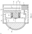
FIG. 6A is a sectional schematic view of the first implementation of the adaptive vehicle headlight according to the first embodiment of the present invention; -
FIG. 6B is a sectional schematic view of a modified example of the first implementation of the adaptive vehicle headlight according to the first embodiment of the present invention; -
FIG. 7 is a sectional schematic view of a second implementation of the adaptive vehicle headlight according to the first embodiment of the present invention; -
FIG. 8 is a perspective exploded sectional view of the second implementation of the adaptive vehicle headlight according to the first embodiment which does not fall within the present invention; -
FIG. 9 is a sectional schematic view of the second implementation of the adaptive vehicle headlight according to the first embodiment which does not fall within the present invention; -
FIG. 10 to FIG. 14 show low beam illumination patterns produced by the adaptive vehicle headlight according to the first embodiment of the present invention, in which a vehicle body is in a tilted or non-tilted state; -
FIG. 15 to FIG. 19 are schematic views showing road illumination of the adaptive vehicle headlight according to the first embodiment of the present invention, in which the vehicle body is in a tilted or non-tilted state; -
FIG. 20 is a schematic view showing an arrangement of a light emitting unit of the adaptive vehicle headlight according to the first embodiment of the present invention; -
FIG. 21 is a schematic view showing another arrangement of the light emitting unit of the adaptive vehicle headlight according to the first embodiment of the present invention; -
FIG. 22 is a perspective partially exploded sectional view of a first implementation of an adaptive vehicle headlight according to a second embodiment of the present invention; -
FIG. 23 is a sectional schematic view of the first implementation of the adaptive vehicle headlight according to the second embodiment of the present invention; -
FIG. 24 is a perspective partially exploded sectional view of a second implementation of the adaptive vehicle headlight according to the second embodiment which does not fall within the present invention; -
FIG. 25 is a sectional schematic view of the second implementation of the adaptive vehicle headlight according to the second embodiment which does not fall within the present invention; -
FIG. 26 is a schematic view showing a first mode of the adaptive vehicle headlight according to the second embodiment of the present invention, in which a light distributing member is moved to a first position through a rotation of a rotating member; -
FIG. 27 is a schematic view showing a second mode of the adaptive vehicle headlight according to the second embodiment of the present invention, in which the light distributing member is moved to a second position through a rotation of the rotating member; -
FIG. 28 andFIG. 29 respectively show a cooperative relationship between the light distributing member and a lifting structure in the adaptive vehicle headlight according to the second embodiment of the present invention; -
FIG. 30 is a schematic view showing an optical design of the adaptive vehicle headlight according to the second embodiment of the present invention; -
FIG. 31 is a perspective partially exploded sectional view of a first implementation of an adaptive vehicle headlight according to a third embodiment which does not fall within the present invention; -
FIG. 32 is a sectional schematic view of the first implementation of the adaptive vehicle headlight according to the third embodiment which does not fall within the present invention; -
FIG. 33 is a perspective partially exploded sectional view of a second implementation of the adaptive vehicle headlight according to the third embodiment which does not fall within the present invention; -
FIG. 34 is a sectional schematic view of the second implementation of the adaptive vehicle headlight according to the third embodiment which does not fall within the present invention; -
FIG. 35 is a schematic view showing a first mode of the adaptive vehicle headlight according to the third embodiment which does not fall within the present invention, in which a light distributing member is moved to a first position through a rotation of a rotating member; -
FIG. 36 is a schematic view showing a second mode of the adaptive vehicle headlight according to the third embodiment which does not fall within the present invention, in which the light distributing member is moved to a second position through a rotation of the rotating member; and -
FIG. 37 andFIG. 38 respectively show a cooperative relationship between the light distributing member and a lifting structure in the adaptive vehicle headlight according to the third embodiment which does not fall within the present invention. - The present invention is more particularly described in the following examples that are intended as illustrative only since numerous modifications and variations therein will be apparent to those skilled in the art. Like numbers in the drawings indicate like components throughout the views. As used in the description herein and throughout the claims that follow, unless the context clearly dictates otherwise, the meaning of "a", "an", and "the" includes plural reference, and the meaning of "in" includes "in" and "on". Titles or subtitles can be used herein for the convenience of a reader, which shall have no influence on the scope of the present invention.
- The terms used herein generally have their ordinary meanings in the art. In the case of conflict, the present document, including any definitions given herein, will prevail. The same thing can be expressed in more than one way. Alternative language and synonyms can be used for any term(s) discussed herein, and no special significance is to be placed upon whether a term is elaborated or discussed herein. A recital of one or more synonyms does not exclude the use of other synonyms. The use of examples anywhere in this specification including examples of any terms is illustrative only, and in no way limits the scope and meaning of the present invention or of any exemplified term. Likewise, the present invention is not limited to various embodiments given herein. Numbering terms such as "first", "second" or "third" can be used to describe various components, signals or the like, which are for distinguishing one component/signal from a second only, and are not intended to, nor should be construed to impose any substantive limitations on the components, signals or the like.
- All illumination patterns as described herein can meet the light distribution requirements of the ECE R113 regulation which regulates headlamps for producing a symmetrical light pattern.
- Referring to
FIG. 1 to FIG. 6B , a first embodiment of the present invention provides an adaptive vehicle headlight Z including alight body 1, anoptical lens 2, adriver 3, and a control unit 4. Theoptical lens 2, thedriver 3, and the control unit 4 are integrated into thelight body 1, specific details of which will be described below. Accordingly, theoptical lens 2, thedriver 3, and the control unit 4 can be isolated from an external environment, and are not easily affected by external environmental factors such as water and dust. The adaptive vehicle headlight Z of the present invention is suitable for two-wheeled vehicles such as fuel motorcycles, electric motorcycles, general bicycles, and electric assisted bicycles. The adaptive vehicle headlight Z of the present invention can be installed on a vehicle body V to provide sufficient front illumination during a turn of a vehicle, so as to reduce or even eliminate blind area of vision in front of the vehicle, thereby improving traffic safety. - More specifically, the
light body 1 includes abase 11, a rotatingmember 12, and alight emitting unit 13. Thebase 11 has a carryingportion 11a. The rotatingmember 12 is configured to rotate relative to thebase 11. Thelight emitting unit 13 is arranged on the carryingportion 11a to emit an illumination light beam. Theoptical lens 2 is connected as a whole to the rotatingmember 12 for light distribution of the illumination light beam. That is, the illumination light beam is projected outwardly through theoptical lens 2 to produce an illumination pattern having a cut-off line. Thedriver 3 is configured to drive the rotatingmember 12. The control unit 4 is configured to cause an operation of thedriver 3 according to a tilt angle of the vehicle body V, such that the rotatingmember 12 synchronously rotates a predetermined angle with theoptical lens 2. - In one implementation of the present embodiment, as shown in
FIG. 6A , thebase 11 is configured to divide an internal space of thelight body 1 into a first space S1 and a second space S2. The carryingportion 11a, the rotatingmember 12, thelight emitting unit 13, theoptical lens 2, and thedriver 13 are all located in the first space S1. The control unit 4 is located in the second space S2. More specifically, the carryingportion 11a has afirst carrying surface 111. Thefirst carrying surface 111 can be opposite to alight input surface 200 of theoptical lens 2, and preferably opposite to and parallel to thelight input surface 200 of theoptical lens 2. Thelight emitting unit 13 is arranged on the first carryingsurface 111 to emit the illumination light beam directly toward thelight input surface 200 of theoptical lens 2. The rotatingmember 12 is arranged to surround the carryingportion 11a, in which a rotation axis 34 coincides with a central axis of the carryingportion 11a. Thedriver 3 is arranged between the rotatingmember 12 and the carryingportion 11a, and can drive the rotatingmember 12 in a non-contact manner (e.g., applying a non-contact force), so as to allow the rotatingmember 12 to synchronously rotate with theoptical lens 2. The above description is for exemplary purposes only and is not intended to limit the scope of the present invention. - In practice, the
base 11 can further has aspacing portion 11b, and the internal space of thelight body 1 can be divided into the first space S1 and the second space S2 by thespacing portion 11b. The carryingportion 11a can be formed to extend from thespacing portion 11b. The rotatingmember 12 can include anouter frame portion 12a, aninner frame portion 12b, and awall portion 12c. Theouter frame portion 12a and theinner frame portion 12b can be spaced apart from each other in an up-down direction. Thewall portion 12c can be connected between theouter frame portion 12a and theinner frame portion 12b, and the first carryingsurface 111 of the carryingportion 11a is exposed from thewall portion 12c. Theoptical lens 2 can be fixed to theouter frame portion 12a. Theoptical lens 2 can be an asymmetric optical lens, in which curvatures in the horizontal direction and the vertical direction are different from each other. Thedriver 3 can be a brushless pan/tilt motor and includes acoil structure 31 and amagnetic body 32. Thecoil structure 31 and themagnetic body 32 can be arranged between theouter frame portion 12a, theinner frame portion 12b, and thewall portion 12c and at a certain distance from each other. Thecoil structure 31 can be composed of iron cores with coils, and themagnetic body 32 can be formed from one or more magnets. The control unit 4 can include a control printed circuit board (PCB) and a tilt sensor (not shown), and at least has control functions of thelight emitting unit 13 and thedriver 3. - Furthermore, as shown in
FIG. 4 andFIG. 6A , anexternal structure 14 of thelight body 1 includes ahousing 14a, alight cover 14b, and aback lid 14c. Thehousing 14a has a firstopen end 141a and a secondopen end 142a opposite to the first open end 141, the shape of which is not limited to a cylindrical shape. The base 11 can be integrally formed inside thehousing 14a. Thelight cover 14b is assembled to the firstopen end 141a of thehousing 14a, and thelight cover 14b, one portion (e.g., a front portion) of thehousing 14a, and the base 11 jointly define the first space S1. Theback lid 14c is assembled to the secondopen end 142a of thehousing 14a, and theback lid 14c and a second portion (e.g., a rear portion) of thehousing 14a jointly define the second space S2. - In addition, as shown in
FIG. 6A , the carryingportion 11a of the base 11 can have a first wire groove G2 for passing wire(s) outwardly from thelight emitting unit 13. Thespacing portion 11b of the base 11 can have a second wire groove G3 for passing wire(s) outwardly from thecoil structure 31. Therefore, these wires cannot be interfered with mechanical parts, so that the headlight can work normally for a long period of time. - In certain embodiments, depending on cost considerations or different use requirements, the control unit 4 can be arranged at the outside of the
light body 1 and electrically connected to thelight emitting unit 13 and the driver 3 (e.g., thecoil structure 31 of the driver 3), as shown inFIG. 6B . In addition, thelight cover 14b can be omitted for cost saving. - In order to neatly and compactly integrate the base 11 with the rotating
member 12 and thedriver 3, the carryingportion 11a can have an accommodating groove G1, and a bearing B is disposed between theinner frame portion 12b and the carryingportion 11a. Preferably, theinner frame portion 12b of the rotatingmember 12 and the bearing B can be jointly disposed in the accommodating groove G1, in which theinner frame portion 12b is supported by the bearing B. Furthermore, the carryingportion 11a can further have asecond carrying surface 112 located outside of the accommodating groove G1 and perpendicular to the first carryingsurface 111. Thecoil structure 31 can be fixed to thesecond carrying surface 112 of the carryingportion 11a, and themagnetic body 32 can be fixed to theouter frame portion 12a of the rotatingmember 12. Accordingly, thecoil structure 31 and themagnetic body 32 can work with each other to produce an electromagnetic torque, thereby allowing the rotatingmember 12 to rotate in a clockwise or counterclockwise direction. - Referring to
FIG. 7 , depending on particular requirements, a portion of the rotatingmember 12 can be independently detached to become a portion of thedriver 3. More specifically, thedriver 3 includes astator portion 3a and arotor portion 3b. Thestator portion 3a includes acoil structure 31. Therotor portion 3b includes amagnetic body 32 and is connected to the rotatingmember 12. Accordingly, when coils in thecoil structure 31 are energized, therotor portion 3b can drive the rotatingmember 12 to synchronously rotate with theoptical lens 2. - Referring to
FIG. 8 andFIG. 9 , in a second implementation of the present embodiment which does not fall within the present invention, thedriver 3 can be a stepper motor that is arranged in the second space S2 of thelight body 1 and has a driving structure 33 (e.g., a driving shaft) extending from the second space S2 to the first space S1 to be transmittingly connected to rotatingmember 12. In practice, a front end of the drivingstructure 33 can be connected to the rotatingmember 12 via a gear set (not shown) that can be composed of a plurality of gears with different diameters. Accordingly, the drivingstructure 33 being rotated can drive the rotatingmember 12 to rotate on the carryingportion 11a by the gear set. That is, the rotational movement of the drivingstructure 33 can be converted into the rotational movement of the rotatingmember 12 by the gear set. - It should be noted that, when a stepper motor is used as the
driver 3, thedriver 3 can be arranged outside of thelight body 1 and connected to the rotatingmember 12 located in thelight body 1 via the drivingstructure 33, such that the rotatingmember 12 can be rotated to the left or right. - Reference is made to
FIG. 10 to FIG. 19 . The adaptive vehicle headlight Z of the present invention can provide sufficient front illumination for a vehicle (e.g., a two-wheeled vehicle) when driving, so as to reduce or even eliminate blind areas BA of vision in front of the vehicle. The detailed descriptions are as follows. When the vehicle is running on a straight road, no rotation is required for theoptical lens 2 since a vehicle body V is maintained perpendicular to a road surface. Thus, an illumination pattern P produced by the adaptive vehicle headlight Z will be in a horizontal state, as shown inFIG. 10 . Therefore, no blind areas of vision are present in front of the vehicle, as shown inFIG. 15 . - When the vehicle is running on a left curved road, the vehicle body V leans to the left at an angle relative to a road surface. At this time, if the
optical lens 2 does not rotate, an illumination pattern P produced by the adaptive vehicle headlight Z would be tilted left, as shown inFIG. 11 , in which a dark area DA is present at the left side of the V-V line and below the H-H line. Therefore, a blind area BA of vision is present at the front left of the vehicle, as shown inFIG. 16 . In contrast, in the present invention, theoptical lens 2 can be driven by the rotatingmember 2 to rotate left by a predetermined angle (i.e., rotate in a clockwise direction viewing from the driver), such that the illumination pattern P is still maintained in the horizontal state and there is a light distribution above the H-H line, as shown inFIG. 12 . Therefore, an auxiliary illumination zone IA can be produced to eliminate the blind area of vision at the front left of the vehicle, as shown inFIG. 17 . - When the vehicle is running on a right curved road, the vehicle body V leans to the right at an angle relative to a road surface. At this time, if the
optical lens 2 does not rotate, an illumination pattern P produced by the adaptive vehicle headlight Z would be tilted right, as shown inFIG. 13 , in which a dark area DA is present at the right side of the V-V line and below the H-H line. Therefore, a blind area BA of vision is present at the front right of the vehicle, as shown inFIG. 18 . In contrast, in the present invention, theoptical lens 2 can be driven by the rotatingmember 2 to rotate right by a predetermined angle (i.e., rotate in a counterclockwise direction viewing from the driver), such that the illumination pattern P is still maintained in the horizontal state and there is a light distribution above the H-H line, as shown inFIG. 14 . Therefore, an auxiliary illumination zone IA can be produced to eliminate the blind area of vision at the front left of the vehicle, as shown inFIG. 19 . - Reference is made to
FIG. 20 andFIG. 21 . In the present embodiment, thelight emitting unit 13 can include a firstlight emitting unit 13a and a secondlight emitting unit 13b, and can further include one or more wavelength converting layers (e.g., fluorescent layers, not shown inFIG. 20 ) covering the firstlight emitting unit 13a and the secondlight emitting unit 13b if necessary, so as to produce optical characteristics required for practical implementations. Thelight emitting unit 13 can be mounted on a circuit substrate, and it can be an LED package structure, but is not limited thereto. The firstlight emitting unit 13a and the secondlight emitting unit 13b are arranged in proximity to alens focus 201, and the firstlight emitting unit 13a is arranged above the secondlight emitting unit 13b. The firstlight emitting unit 13a can include at least twofirst LED chips 131a. The secondlight emitting unit 13b can include at least onesecond LED chip 131b. An illumination light beam emitted from the firstlight emitting unit 13a that is lighted up can be projected outwardly through theoptical lens 2 to produce a low beam illumination pattern. An illumination light beam emitted from the firstlight emitting unit 13a and the secondlight emitting unit 13b that are lighted up at the same time can be projected outwardly through theoptical lens 2 to produce a high beam illumination pattern. The above description is for exemplary purposes only and is not intended to limit the scope of the present invention. - More specifically, in a structure with two
first LED chips 131a and a secondlight emitting unit 13b, the twofirst LED chips 131a can be arranged above thelens focus 201 and symmetrically distributed at left and right sides of avertical symmetry plane 201s passing through thelens focus 201. The secondlight emitting unit 13b can be arranged at thelens focus 201. In use, in a situation where theoptical lens 2 does not rotate, the twofirst LED chips 131a can be lighted up in a low beam mode, and the twofirst LED chips 131a and the secondlight emitting unit 13b can be lighted up in a high beam mode. - In a situation where the
optical lens 2 rotates to the left, all or the left one of the twofirst LED chips 131a can be lighted up in a low beam mode. It should be noted that, when all of the twofirst LED chips 131a are lighted up, a resulting illumination pattern P would have an amount of light spilling beyond the H-H line, i.e., a cut-off line CF of the resulting illumination pattern P would be located above the H-H line, as shown inFIG. 12 . When only the left one of the twofirst LED chips 131a is lighted up, the amount of light spilling would be eliminated, i.e., the cut-off line CF of the resulting illumination pattern P would be located below and close to the H-H line. In addition, in a high beam mode, the twofirst LED chips 131a and the secondlight emitting unit 13b can be lighted up, or the left one of the twofirst LED chips 131a and the secondlight emitting unit 13b can be lighted up. - In a situation where the
optical lens 2 rotates to the right, all or the right one of the twofirst LED chips 131a can be lighted up in a low beam mode. It should be noted that, when all of the twofirst LED chips 131a are lighted up, a resulting illumination pattern P would have an amount of light spilling beyond the H-H line, i.e., a cut-off line CF of the resulting illumination pattern P would be located above the H-H line, as shown inFIG. 14 . When only the right one of the twofirst LED chips 131a is lighted up, the amount of light spilling would be eliminated, i.e., the cut-off line CF of the resulting illumination pattern P would be located below and close to the H-H line. In addition, in a high beam mode, the twofirst LED chips 131a and the secondlight emitting unit 13b can be lighted up, or the right one of the twofirst LED chips 131a and the secondlight emitting unit 13b can be lighted up. - In some applications, in order to increase illumination brightness, the first
light emitting unit 13a includes fourfirst LED chips 131a and the secondlight emitting unit 13b includes twosecond LED chips 131b. The fourfirst LED chips 131a can be arranged above thelens focus 201 and symmetrically distributed in pairs at left and right sides of avertical symmetry plane 201s. The twosecond LED chips 131b correspond in position to thelens focus 201 and symmetrically distributed at left and right sides of thevertical symmetry plane 201s. Furthermore, the twosecond LED chips 131b are respectively aligned with the middle two of the fourfirst LED chips 131a in the up-down direction. In use, in a situation where theoptical lens 2 does not rotate, all or the middle two of the fourfirst LED chips 131a can be lighted up in a low beam mode. In a high beam mode, the fourfirst LED chips 131a and the twosecond LED chips 131b can be lighted up, or the middle two of the fourfirst LED chips 131a and the twosecond LED chips 131b can be lighted up. - In a situation where the
optical lens 2 rotates to the left, in a low beam mode, all of the fourfirst LED chips 131a can be lighted up, or the first one or two of the fourfirst LED chips 131a located at the left side of thevertical symmetry plane 201s can be lighted up. When all of the fourfirst LED chips 131a are lighted up, a resulting illumination pattern P would have an amount of light spilling beyond the H-H line, i.e., a cut-off line CF of the resulting illumination pattern P would be located above the H-H line, as shown inFIG. 12 . When the first one or two of the fourfirst LED chips 131a located at the left side of thevertical symmetry plane 201s are lighted up, the amount of light spilling would be eliminated, i.e., the cut-off line CF of the resulting illumination pattern P would be located below and close to the H-H line. In addition, in a high beam mode, the fourfirst LED chips 131a and the twosecond LED chips 131b can be lighted up, or the first one or two of the fourfirst LED chips 131a located at the left side of thevertical symmetry plane 201s and the twosecond LED chips 131b can be lighted up. - In a situation where the
optical lens 2 rotates to the right, in a low beam mode, all of the fourfirst LED chips 131a can be lighted up, or the first one or two of the fourfirst LED chips 131a located at the right side of thevertical symmetry plane 201s can be lighted up. When all of the fourfirst LED chips 131a are lighted up, a resulting illumination pattern P would have an amount of light spilling beyond the H-H line, i.e., a cut-off line CF of the resulting illumination pattern P would be located above the H-H line, as shown inFIG. 14 . When the first one or two of the fourfirst LED chips 131a located at the right side of thevertical symmetry plane 201s are lighted up, the amount of light spilling would be eliminated, i.e., the cut-off line CF of the resulting illumination pattern P would be located below and close to the H-H line. In addition, in a high beam mode, the fourfirst LED chips 131a and the twosecond LED chips 131b can be lighted up, or the first one or two of the fourfirst LED chips 131a located at the right side of thevertical symmetry plane 201s and the twosecond LED chips 131b can be lighted up. - Preferably, two of the four
first LED chips 131a located at the left or right side of thevertical symmetry plane 201s has a first spacing D1 therebetween. The middle two of the fourfirst LED chips 131a has a second spacing D2 therebetween. The twosecond LED chips 131b has a third spacing D3 therebetween, and a fourth spacing D4 is present between each of the twosecond LED chips 131b and the corresponding one of the twosecond LED chips 131b. The first spacing D1, the second spacing D2, the third spacing D3, and the fourth spacing D4 satisfy the equations (1) to (4):


- In some applications, only the first
light emitting unit 13a is included in the adaptive vehicle headlight Z, which can include one or morefirst LED chips 131a. For example, the firstlight emitting unit 13a can include fourfirst LED chips 131a arranged to satisfy the equations (1) to (4). As a result, the adaptive vehicle headlight Z can only produce a low beam illumination pattern. - Referring to
FIG. 22 to FIG. 29 , which are to be read in conjunction withFIG. 1 to FIG. 4 , a second embodiment of the present invention provides an adaptive vehicle headlight Z including alight body 1, anoptical lens 2, adriver 3, and a control unit 4. Theoptical lens 2, thedriver 3, and the control unit 4 are integrated into thelight body 1. More specifically, thelight body 1 includes abase 11, a rotatingmember 12, and alight emitting unit 13. Thebase 11 has a carryingportion 11a. The rotatingmember 12 is configured to rotate relative to thebase 11. Thelight emitting unit 13 is arranged on the carryingportion 11a to emit an illumination light beam. Theoptical lens 2 is connected as a whole to the rotatingmember 12 for light distribution of the illumination light beam. That is, the illumination light beam is projected outwardly through theoptical lens 2 to produce an illumination pattern having a cut-off line. Thedriver 3 is configured to drive the rotatingmember 12. The control unit 4 is configured to cause an operation of thedriver 3 according to a tilt angle of a vehicle body V, such that theoptical lens 2 can be driven by the rotatingmember 12 to rotate a predetermined angle. The necessary details of thelight body 1, theoptical lens 2, thedriver 3, and the control unit 4 are described in the first embodiment, and will not be reiterated herein. - The main difference of the present embodiment from the first embodiment is that the
light body 1 further includes alight distributing member 15 arranged between theoptical lens 2 and thelight emitting unit 3. It is worth mentioning that thelight distributing member 15 can adjust the distribution of the illumination light beam, such that the illumination pattern can have a clearer cut-off line and contour. If the illumination pattern is a low beam illumination pattern, the cut-off line thereof is located below the H-H line (i.e., there is no light distribution above the H-H line). Thelight distributing member 15 can be a light shielding plate, a free end of which is not connected to other parts and has an optically effective edge (also called cut-off edge) to produce a different light distribution effect, but the present invention is not limited thereto. - In the present embodiment, the
light distributing member 15 is connected as a whole to the rotatingmember 12, such that it can be driven by the rotatingmember 12 to reciprocally move between a first position as shown inFIG. 26 and a second position as shown inFIG. 27 to selectively cover thelight emitting unit 13. Accordingly, adaptive vehicle headlight Z can be switched between a low beam mode and a high beam mode. In the low beam mode, thelight distributing member 15 is located at the first position. In the high beam mode, thelight distributing member 15 is located at the second position. - In one implementation of the present embodiment, the rotating
member 12 is driven in a non-contact manner. More specifically, as shown inFIG. 22 andFIG. 23 , thedriver 3 can be a brushless pan/tilt motor and includes acoil structure 31 and amagnetic body 32. Thecoil structure 31 and themagnetic body 32 can be arranged between anouter frame portion 12a, aninner frame portion 12b, and awall portion 12c and at a certain distance from each other. Accordingly, thecoil structure 31 and themagnetic body 32 can work with each other to produce an electromagnetic torque, thereby allowing the rotatingmember 12 to rotate in a clockwise or counterclockwise direction. Thecoil structure 31 can be composed of iron cores with coils, and themagnetic body 32 can be formed from one or more magnets, but the present invention is not limited thereto. - In a second implementation of the present embodiment which does not fall within the present invention, the rotating
member 12 is driven in a direct contact manner. More specifically, as shown inFIG. 24 andFIG. 25 , thedriver 3 can be a stepper motor and has a driving structure 33 (e.g., a driving shaft) transmittingly connected to rotatingmember 12 to provide driving force for rotation, thereby allowing the rotatingmember 12 to rotate in a clockwise or counterclockwise direction. The drivingstructure 33 can be connected to the rotatingmember 12 via a gear set (not shown inFIG. 24 andFIG. 25 ) that can be composed of a plurality of gears with different diameters, but the present invention is not limited thereto. - In order to realize an optical system having low beam and high beam modes, the
light emitting unit 13 can include a firstlight emitting unit 13a and a secondlight emitting unit 13b. The firstlight emitting unit 13a and the secondlight emitting unit 13b are arranged in proximity to alens focus 201, and the firstlight emitting unit 13a is arranged above the secondlight emitting unit 13b. More details about the light-emittingunit 13 are provided in the first embodiment andFIG. 20 andFIG. 21 . Thelight distributing member 15 located at the first position covers the secondlight emitting unit 13b, as shown inFIG. 26 , such that a resulting illumination pattern is a low beam illumination pattern. Thelight distributing member 15 located at the second position allows the firstlight emitting unit 13a and the secondlight emitting unit 13b to be exposed therefrom, as shown inFIG. 27 , such that a resulting illumination pattern is a high beam illumination pattern. - It is worth mentioning that, in the optical system of the present embodiment, the arrangement of the light-emitting
unit 13 is not limited to those shown inFIG. 20 andFIG. 21 . In the presence of thelight distributing member 15, the light-emittingunit 13 can include one or more LED chips. - More specifically, the
light distributing member 15 is fixed to thewall portion 12c and connected to theouter frame portion 12a of the rotatingmember 2 via a balancingmember 16. The balancingmember 16 can be a spring, but is not limited thereto. In use, in a low beam mode, the balancingmember 16 is in an original state to lift up thelight distributing member 15 to the first position. In a high beam mode, the balancingmember 16 is in a compressed state to allow thelight distributing member 15 to be guided to the second position. - In practice, as shown in
FIG. 28 andFIG. 29 , the carryingportion 11a of the base 11 can have a liftingstructure 113 with afirst guiding surface 1131. In addition, thelight distributing member 15 can have a guidingstructure 152 with asecond guiding surface 1521. Each of thefirst guiding surface 1131 and thesecond guiding surface 1521 can be an arc surface. Accordingly, thelight distributing member 15 can be guided by the guidingstructure 152 and lifted up to the second position by the liftingstructure 113. That is, thelight distributing member 15 is lifted up to the second position by the slidable cooperation of thesecond guiding surface 1521 of the guidingstructure 152 with thefirst guiding surface 1131 of the liftingstructure 113. The above description is for exemplary purposes only and is not intended to limit the scope of the present invention. - Although
FIG. 27 to FIG. 29 shows that thelight distributing member 15 is moved up by a contact force produced between the light distributingmember 15 and the carryingportion 11a of thebase 11, in practice, thelight distributing member 15 can be moved up by a non-contact force produced between the light distributingmember 15 and the carryingportion 11a of thebase 11. In an embodiment not shown in the above figures, magnetic components can be arranged between the light distributingmember 15 and the carryingportion 11a of thebase 11. The magnetic components can produce a magnetic force such as a magnetic attraction force to raise thelight distributing member 15 to a predetermined height, or produce another magnetic force such as a magnetic repulsion force to lower thelight distributing member 15 to an initial height. - In some applications, as shown in
FIG. 23 ,FIG. 26 , andFIG. 27 , a limitingmember 17 can be arranged between the light distributingmember 15 and theouter frame portion 12a of the rotatingmember 12 to limit the balancing member 16 (e.g., a horizontal movement of the balancing member 16). The limitingmember 17 can be a limiting pin, but is not limited thereto. More specifically, thelight distribution member 15 can have apin hole 153 at the bottom thereof. The limitingmember 17 can pass through thepin hole 153 and a distal end thereof can be inserted into and fixed in position to theouter frame portion 12a of the rotatingmember 12. - Reference is made to
FIG. 30 , in a preferable design of the optical system of the present embodiment, thelight emitting unit 13 has alight emitting surface 130, and the center point P of thelight emitting surface 130 is flush with an opticallyeffective edge 151 of thelight distributing member 15. Furthermore, thelight distributing member 15 has aninner surface 150 opposite to thelight emitting surface 130, and a horizontal distance D5 between theinner surface 150 and thelight emitting surface 130 satisfies: 0 mm < horizontal distance D5 ≤ 1.0 mm. - Referring to
FIG. 31 to FIG. 38 , a third embodiment which does not fall within the present invention provides an adaptive vehicle headlight Z including alight body 1, anoptical lens 2, adriver 3, and a control unit 4. Theoptical lens 2, thedriver 3, and the control unit 4 are integrated into thelight body 1. More specifically, thelight body 1 includes abase 11, alight emitting unit 13, alight guiding member 18, a rotatingmember 12, and alight distributing member 15. Thelight emitting unit 13 and thelight guiding member 18 are arranged on thebase 11, and thelight emitting unit 13 is configured to emit an illumination light beam toward thelight guiding member 18. The rotatingmember 12 is configured to rotate relative to thebase 11. Thelight distributing member 15 is connected as a whole to the rotatingmember 12. Theoptical lens 2 is configured to project the illumination light beam outwardly so as to produce an illumination pattern having a cut-off line. Thelight distributing member 15 is arranged between theoptical lens 2 and thelight emitting unit 13. Thedriver 3 is configured to drive the rotatingmember 12. The control unit 4 is configured to cause an operation of thedriver 3 according to a low beam mode and a high beam mode, such that thelight distributing member 15 is driven by the rotatingmember 12 to move to a first position or a second position. - In the present embodiment, the
base 11 has a carrying surface 111' perpendicular to alight input surface 200 of theoptical lens 2 and located below a lensoptical axis 202. Thelight emitting unit 13 and thelight guiding member 18 are arranged on the carrying surface 111', and the illumination light beam emitted from thelight emitting unit 13 is guided by thelight guiding member 18 and transmitted to thelight input surface 200 of theoptical lens 2 along a predetermined path. The rotatingmember 12 is connected to thedriver 3, and the rotatingmember 12 and thedriver 3 are each at a position avoiding the predetermined path along which the illumination light beam is transmitted. - In the above-mentioned structure, as shown in
FIG. 35 , thelight distributing member 15 located at the first position can shield a portion of the illumination light beam transmitted along the predetermined path, so as to produce a low beam illumination pattern. As shown inFIG. 36 , thelight distributing member 15 located at the second position can allow all the illumination light beam transmitted along the predetermined path to enter theoptical lens 2 through thelight input surface 200, so as to produce a high beam illumination light pattern. - More specifically, the
base 11 has a carryingportion 11a and aspacing portion 11b. Thespacing portion 11b is configured to divide the internal space of thelight body 1 into a first space S1 and a second space S2. Thespacing portion 11b has anopening 114, and the first space S1 is in spatial communication with the second space S2 via theopening 114. The carryingportion 11a has the carrying surface 111'. The rotatingmember 12, thelight distributing member 15, and theoptical lens 2 are located in the first space S1. Thedriver 3 can be located the first space S1 or the second space S2. - It should be noted that, the definition of the
light body 1, in which the internal space is divided into the first space S1 and the second space S2, is for ease of illustration of the positional relationship between the rotatingmember 12, thelight emitting unit 13, and thelight distributing member 15, the present invention is not limited thereto. In certain embodiments, the rotatingmember 12 and thelight distributing member 15 can be located in the second space S2 and between thelight emitting unit 13 and theoptical lens 2. In such a structure, if thespacing portion 11b is closer to thelight emitting unit 13, the rotatingmember 12 and thelight distributing member 15 would be farther away from thelight emitting unit 13. If thespacing portion 11b is farther away from thelight emitting unit 13, the rotatingmember 12 and thelight distributing member 15 would be closer to thelight emitting unit 13. - As shown in
FIG. 31 andFIG. 32 , an external structure of thelight body 1 includes ahousing 14a and alight cover 14b. Thehousing 14a has anopen end 140a and a closed end (not numbered), the shape of which is not limited to a cylindrical shape. Thelight cover 14b is assembled to theopen end 140a of thehousing 14a. The base 11 can be integrally formed inside thehousing 14a. One portion (e.g., a front portion) of thehousing 14a and thespacing portion 11b of the base 11 jointly define the first space S1, and a second portion (e.g., a rear portion) of thehousing 14a and thespacing portion 11b of the base 11 jointly define the second space S2. - Depending on particular requirements, another open end can be formed in place of the closed end of the
housing 14a and is closed by a back lid. Other relevant details are provided in the first embodiment andFIG. 4 to FIG. 6 . - In one implementation of the present embodiment, the rotating
member 12 is driven in a non-contact manner. More specifically, as shown inFIG. 31 andFIG. 32 , thedriver 3 is arranged in the first space S1 of thelight body 1. Thedriver 3 can be a brushless pan/tilt motor and includes astator portion 3a and arotor portion 3b. Thestator portion 3a can be connected to thespacing portion 11b of thebase 11, and therotor portion 3b can rotate in a clockwise or counterclockwise direction about a rotation axis 34 by cooperating with thestator portion 3a. The rotation axis 34 can coincide with or be slightly offset from the lensoptical axis 202. In practice, thestator portion 3a can include a coil structure (not shown inFIG. 31 andFIG. 32 ) that can be composed of iron cores with coils. Therotor portion 3b can include a magnetic body (not shown inFIG. 31 andFIG. 32 ) that can be formed from one or more magnets. The rotatingmember 12 can be connected to therotor portion 3b so as to synchronously rotate with therotor portion 3b. The rotatingmember 12 is not limited to have a disc shape, and it is formed with a hollow area corresponding in position to theopening 114 of thespacing portion 11b. - In a second implementation of the present embodiment, the rotating
member 12 is driven in a direct contact manner. More specifically, as shown inFIG. 33 andFIG. 34 , thedriver 3 is arranged in the second space S2 of thelight body 1. Thedriver 3 can be a stepper motor and has a driving structure 33 (e.g., a driving shaft) transmittingly connected to rotatingmember 12 to provide driving force for rotation, thereby allowing the rotatingmember 12 to rotate in a clockwise or counterclockwise direction. The drivingstructure 33 can extend from the second space S2 to the first space S1 and be connected to the rotatingmember 12 via a gear set (not shown inFIG. 33 andFIG. 34 ) that can be composed of a plurality of gears with different diameters, but the present invention is not limited thereto. - The control unit 4 can include a control printed circuit board (PCB) and at least has control functions of the
light emitting unit 13 and thedriver 3. AlthoughFIG. 32 shows that the control unit 4 is arranged above thelight guiding member 18, the arrangement position of the control unit 4 can be adjusted depending on particular requirements. In certain embodiments, depending on cost considerations or different use requirements, the control unit 4 can be arranged at the outside of thelight body 1 and electrically connected to thelight emitting unit 13 and the driver 3 (e.g., thecoil structure 31 of the driver 3). - In an optical system of the present embodiment, the carrying surface 111' is located below the lens
optical axis 202. Thelight guiding member 18 has a reflecting surface 180 that can define a first focus F1 and a second focus F2. Thelight guiding member 18 can be a light reflecting cup, but is not limited thereto. The first focus F1 is located in a cover region of thelight guiding member 18, and it is located on the lensoptical axis 202 or below the lensoptical axis 202, and preferably below the lensoptical axis 202. The second focus F2 is located outside of the cover region of thelight guiding member 18, and it coincides with thelens focus 201 or is in proximity to thelens focus 201, and preferably coincides with thelens focus 201. - The
light emitting unit 13 is arranged on the carrying surface 111' in a manner that alight emitting surface 130 thereof faces upward (i.e., thelight emitting surface 130 is parallel to the carrying surface 111'). Thelight emitting unit 13 can be located at the first focus F1 or in proximity to the first focus F1. Thelight emitting unit 13 can be an LED package structure, which can include one or more LED chips, and can further include one or more wavelength converting layers (e.g., fluorescent layers) covering the LED chips, so as to produce optical characteristics required for practical implementations. In a structure with alight emitting unit 13 that includes a plurality of LED chips, the arrangement of the LED chips is not particularly limited and can be adjusted depending on particular requirements. In use, the illumination light beam emitted from thelight emitting unit 13 can be reflected by thelight guiding member 18 to transmit toward thelight input surface 200 of theoptical lens 2. In consideration of the light output of thelight emitting unit 13, the carryingportion 11a can further has a stage differential surface 112' connected to the carrying surface 111'. The stage differential surface 112' is extends downwardly and obliquely to thespacing portion 11b. Accordingly, the carryingportion 11a can be arranged without interfering with the transmission path of the illumination light beam so as to reduce light transmission loss. - The
light distributing member 15 includes anupright portion 15a and aninclined portion 15b. Theupright portion 15a is fixed to the rotatingmember 12. Theinclined portion 15b extends toward thespacing portion 11b of the base 11 from theupright portion 15a, and a free end thereof is not connected to other parts and has an opticallyeffective edge 151. In practice, theoptical lens 2 can be an optical lens with circular symmetry, in which curvatures in the horizontal direction are the same as those in the vertical direction. When thelight distributing member 15 is located at the first position, thelens focus 201 would be located on or in proximity to the opticallyeffective edge 151, and preferably on the opticallyeffective edge 151. Accordingly, thelight distributing member 15 can shield a portion of light transmitted toward thelight input surface 200 of theoptical lens 2, and a resulting illumination pattern is a low beam illumination patter. When thelight distributing member 15 is located at the second position, the opticallyeffective edge 151 would be located above thelens focus 201. Accordingly, thelight distributing member 15 can allow all the illumination light beam to enter theoptical lens 2 through thelight input surface 200, and a resulting illumination pattern is a high beam illumination patter. -
FIG. 31 to FIG. 38 show that theupright portion 15a and theinclined portion 15b are included in thelight distributing member 15. However, in certain embodiments, only theupright portion 15a or theinclined portion 15b is included in thelight distributing member 15. - In practice, as shown in
FIG. 37 andFIG. 38 , thespacing portion 11b of the base 11 can have a liftingstructure 113 with afirst guiding surface 1131. In addition, theupright portion 15a of thelight distributing member 15 can have a guidingstructure 152 with asecond guiding surface 1521. Each of thefirst guiding surface 1131 and thesecond guiding surface 1521 can be an arc surface. Accordingly, thelight distributing member 15 can be guided by the guidingstructure 152 and lifted up to the second position by the liftingstructure 113. That is, thelight distributing member 15 is lifted up to the second position by the slidable cooperation of thesecond guiding surface 1521 of the guidingstructure 152 with thefirst guiding surface 1131 of the liftingstructure 113. The above description is for exemplary purposes only and is not intended to limit the scope of the present invention which is defined by the appended claims. - The foregoing description of the exemplary embodiments of the invention has been presented only for the purposes of illustration and description and is not intended to be exhaustive or to limit the invention to the precise forms disclosed. Many modifications and variations are possible in light of the above teaching.
- The embodiments were chosen and described in order to explain the principles of the invention and their practical application so as to enable others skilled in the art to utilize the invention and various embodiments and with various modifications as are suited to the particular use contemplated. Alternative embodiments will become apparent to those skilled in the art to which the present invention pertains without departing from its scope.
Claims (8)
- An adaptive vehicle headlight (Z) for use in a vehicle body (V), comprising:a light body (1) including a base (11), a rotating member (12) and a light emitting unit (13), the base (11) including a carrying portion (11a) that has a first carrying surface (111), the rotating member (12) being configured to rotate relative to the base (11) and surrounding the carrying portion (11a), the light emitting unit (13) being disposed on the first carrying surface (111) to emit an illumination light beam; wherein the rotating member (12) includes an outer frame portion (12a), an inner frame portion (12b), and a wall portion (12c), the outer frame portion (12a) and the inner frame portion (12b) are spaced apart from each other and the wall portion (12c) is connected between the outer frame portion (12a) and the inner frame portion (12b), and the carrying portion (11a) is exposed from the wall portion (12c);an optical lens (2) fixed to the outer frame portion (12a) to allow the illumination light beam to project outwardly so as to produce an illumination pattern (P); wherein the optical lens (2) has a light input surface (200) and the first carrying surface (111) is opposite to the light input surface (200), such that the illumination light beam is emitted towards the light input surface (200),a driver (3) arranged in the light body to drive the rotating member (12) anda control unit (4) arranged in the light body (1) to cause an operation of the driver (3) according to a tilt angle of the vehicle body (V), such that the optical lens (2) is driven by the rotating member (12) to rotate a predetermined angle,characterized in that the driver (3) includes a coil structure (31) and a magnetic body (32), and the coil structure (31) and the magnetic body (32) are disposed between the outer frame portion (12a), the inner frame portion (12b) and the wall portion (12c); wherein the carrying portion (11a) has an accommodating groove (G1), the inner frame portion (12b) and a bearing (B) are jointly disposed in the accommodating groove (G1), and the inner frame portion (12b) is supported by the bearing (B).
- The adaptive vehicle headlight (Z) according to claim 1, wherein the base (11) includes a spacing portion (11b) and the carrying portion (11a) extends from the spacing portion (11b), the carrying portion (11a) has a first wire groove (G2) for passing wires outwardly from the light emitting unit (13), and the spacing portion (11b) has a second wire groove (G3) for passing wires outwardly from the coil structure (32).
- The adaptive vehicle headlight (Z) according to claim 1 or 2, wherein the carrying portion (11a) has a second carrying surface (112) that is located outside the accommodating groove (G1) and is perpendicular to the first carrying surface (111); wherein the coil structure (31) is fixed to the second carrying surface (112), and the magnetic body (32) is fixed to the outer frame portion (12a).
- The adaptive vehicle headlight (Z) according to any one of claims 1 to 3, wherein the light body (1) includes a light distributing member (15) that is arranged between the optical lens (2) and the light emitting unit (13) and connected as a whole to the rotating member (12).
- The adaptive vehicle headlight (Z) according to claim 4, wherein the light distributing member (15) is configured to be driven by the rotating member (12) to move to a first position or a second position, so as to selectively cover the light emitting unit (13); wherein the light emitting unit (13) includes a first light emitting unit (13a) and a second light emitting unit (13b), and the first light emitting unit (13a) is arranged above the second light emitting unit (13b); wherein the light distributing member (15) is located at the second position to allow the first light emitting unit (13a) and the second light emitting unit (13b) to be exposed therefrom, such that the illumination pattern (P) is a high beam illumination pattern.
- The adaptive vehicle headlight (Z) according to claim 5, wherein the light distributing member (15) is fixed to the wall portion (12c) and connected to the outer frame portion (12a) via a balancing member (16), and a limiting member (17) is arranged between the light distributing member (15) and the outer frame portion (12a) to limit the balancing member (16); wherein the balancing member (16) is in an original state when the light distributing member (15) is located at the first position, and the balancing member (16) is in a compressed state when the light distributing member (15) is located at the second position.
- The adaptive vehicle headlight according to claim 6, wherein the carrying portion (11a) has a lifting structure (113) and the light distributing member (15) has a guiding structure (152), and the light distributing member (15) is guided by the guiding structure (152) and lifted up to the second position by the lifting structure (113).
- The adaptive vehicle headlight according to claim 7, wherein the lifting structure (113) has a first guiding surface (1131), and the guiding structure (152) has a second guiding surface (1521) for slidable cooperation with the first guiding surface (1131), so as to allow the light distributing member (15) to abut against the lifting structure (113).
Applications Claiming Priority (1)
| Application Number | Priority Date | Filing Date | Title |
|---|---|---|---|
| TW110109927A TWI774279B (en) | 2021-03-19 | 2021-03-19 | Adaptive vehicle headlight |
Publications (3)
| Publication Number | Publication Date |
|---|---|
| EP4059776A1 EP4059776A1 (en) | 2022-09-21 |
| EP4059776B1 true EP4059776B1 (en) | 2024-12-25 |
| EP4059776C0 EP4059776C0 (en) | 2024-12-25 |
Family
ID=80787482
Family Applications (1)
| Application Number | Title | Priority Date | Filing Date |
|---|---|---|---|
| EP22162804.3A Active EP4059776B1 (en) | 2021-03-19 | 2022-03-17 | Adaptive vehicle headlight |
Country Status (5)
| Country | Link |
|---|---|
| US (1) | US11970235B2 (en) |
| EP (1) | EP4059776B1 (en) |
| JP (1) | JP7417646B2 (en) |
| CN (1) | CN115107632A (en) |
| TW (1) | TWI774279B (en) |
Families Citing this family (7)
| Publication number | Priority date | Publication date | Assignee | Title |
|---|---|---|---|---|
| USD1001328S1 (en) * | 2019-09-09 | 2023-10-10 | Chen Shu Yueh | Light frame for automobile |
| TWI866702B (en) * | 2023-02-06 | 2024-12-11 | 王正 | Intelligent adaptive illumination device |
| TWI851003B (en) | 2023-02-06 | 2024-08-01 | 王正 | Intelligent adaptive illumination device |
| TWI866111B (en) * | 2023-03-15 | 2024-12-11 | 王正 | Illumination device for vehicle |
| TWI874928B (en) * | 2023-03-17 | 2025-03-01 | 王正 | High air tightness headlamp for vehicle |
| US12304586B1 (en) | 2024-03-18 | 2025-05-20 | Eiso Enterprise Co., Ltd. | Bicycle headlight system |
| US12391169B1 (en) | 2024-04-19 | 2025-08-19 | Alexandro De La Torre | Adjustable headlight device |
Family Cites Families (19)
| Publication number | Priority date | Publication date | Assignee | Title |
|---|---|---|---|---|
| JPH0810563B2 (en) * | 1986-12-22 | 1996-01-31 | 株式会社小糸製作所 | Vehicle headlights |
| JP2542837B2 (en) * | 1986-12-26 | 1996-10-09 | 株式会社小糸製作所 | Vehicle headlights |
| JPH01173095U (en) * | 1988-05-27 | 1989-12-07 | ||
| JP2542837Y2 (en) * | 1991-12-27 | 1997-07-30 | 京セラ株式会社 | Indexable end mill |
| US5426571A (en) * | 1993-03-11 | 1995-06-20 | Jones; Jerry | Motorcycle headlight aiming device |
| JPH0741808U (en) * | 1993-12-27 | 1995-07-21 | 市光工業株式会社 | Adjustable projector headlamp with cut line |
| FR2805598B1 (en) * | 2000-02-25 | 2002-04-26 | Renault | MOTOR VEHICLE HEADLIGHT PROJECTOR WITH LIGHT GUIDES |
| JP2001325817A (en) * | 2000-05-15 | 2001-11-22 | Koito Mfg Co Ltd | Vehicle headlights |
| EP1288069B1 (en) * | 2001-08-24 | 2009-12-16 | Stanley Electric Co., Ltd. | Vehicle headlight |
| JP4688220B2 (en) * | 2006-10-10 | 2011-05-25 | 株式会社小糸製作所 | Vehicle lamp |
| US8858046B2 (en) * | 2010-06-28 | 2014-10-14 | Koito Manufacturing Co., Ltd. | Control apparatus for vehicle lamp, vehicle lighting system, and vehicle lamp |
| TW201242814A (en) * | 2011-04-28 | 2012-11-01 | qing-yun Huang | High beam and low beam control device for car lamp |
| CN102954421B (en) * | 2011-08-18 | 2018-04-17 | 现代摩比斯株式会社 | Vehicle lamp and its control method |
| JP5866930B2 (en) | 2011-09-29 | 2016-02-24 | 株式会社ニデック | Eye refractive power measuring device |
| US8992056B2 (en) * | 2012-02-03 | 2015-03-31 | I/O Controls Corporation | Vehicle headlight and alert system |
| ITMI20131056A1 (en) * | 2013-06-25 | 2014-12-26 | R L | FLAP LENS PROJECTOR FOR TWO-WHEEL VEHICLES |
| JP5642246B1 (en) | 2013-10-23 | 2014-12-17 | 三菱電機株式会社 | Variable light distribution headlamp |
| US9945528B2 (en) * | 2013-11-19 | 2018-04-17 | Mitsubishi Electric Corporation | Headlight module and headlight device |
| WO2015115319A1 (en) * | 2014-01-30 | 2015-08-06 | 三菱電機株式会社 | Headlight device |
-
2021
- 2021-03-19 TW TW110109927A patent/TWI774279B/en active
-
2022
- 2022-01-18 CN CN202210055639.4A patent/CN115107632A/en active Pending
- 2022-03-07 JP JP2022034265A patent/JP7417646B2/en active Active
- 2022-03-17 EP EP22162804.3A patent/EP4059776B1/en active Active
- 2022-03-17 US US17/697,055 patent/US11970235B2/en active Active
Also Published As
| Publication number | Publication date |
|---|---|
| TWI774279B (en) | 2022-08-11 |
| TW202237445A (en) | 2022-10-01 |
| JP2022145572A (en) | 2022-10-04 |
| CN115107632A (en) | 2022-09-27 |
| US11970235B2 (en) | 2024-04-30 |
| EP4059776A1 (en) | 2022-09-21 |
| EP4059776C0 (en) | 2024-12-25 |
| JP7417646B2 (en) | 2024-01-18 |
| US20220297780A1 (en) | 2022-09-22 |
Similar Documents
| Publication | Publication Date | Title |
|---|---|---|
| EP4059776B1 (en) | Adaptive vehicle headlight | |
| US7575352B2 (en) | Vehicular headlamp | |
| US8506147B2 (en) | Light source and vehicle lamp | |
| JP5414246B2 (en) | Vehicle headlamp | |
| US10502387B2 (en) | Smart headlight | |
| EP2322848A2 (en) | Vehicle light | |
| JP2006202694A (en) | Vehicle headlamp | |
| JP7753818B2 (en) | Lamp units, vehicle lighting fixtures | |
| CN107448854B (en) | Rotary lamp module | |
| US20240052986A1 (en) | Vehicle light fixture | |
| EP4151509B1 (en) | Adaptive illuminating headlight | |
| TWM626668U (en) | Adaptive vehicle headlights | |
| US12269554B2 (en) | Intelligent follow-up illumination device including support component | |
| US6578995B2 (en) | Vehicular headlamp and vehicle provided with same | |
| CN107448855A (en) | Rotate lighting module | |
| JP4442754B2 (en) | head lamp | |
| EP4653759A1 (en) | Vehicle lamp | |
| JP7382199B2 (en) | vehicle headlights | |
| CN118973864A (en) | Lighting system | |
| WO2024203061A1 (en) | Vehicle headlight | |
| TW202432990A (en) | Intelligent adaptive illumination device |
Legal Events
| Date | Code | Title | Description |
|---|---|---|---|
| PUAI | Public reference made under article 153(3) epc to a published international application that has entered the european phase |
Free format text: ORIGINAL CODE: 0009012 |
|
| STAA | Information on the status of an ep patent application or granted ep patent |
Free format text: STATUS: THE APPLICATION HAS BEEN PUBLISHED |
|
| AK | Designated contracting states |
Kind code of ref document: A1 Designated state(s): AL AT BE BG CH CY CZ DE DK EE ES FI FR GB GR HR HU IE IS IT LI LT LU LV MC MK MT NL NO PL PT RO RS SE SI SK SM TR |
|
| STAA | Information on the status of an ep patent application or granted ep patent |
Free format text: STATUS: REQUEST FOR EXAMINATION WAS MADE |
|
| 17P | Request for examination filed |
Effective date: 20230316 |
|
| RBV | Designated contracting states (corrected) |
Designated state(s): AL AT BE BG CH CY CZ DE DK EE ES FI FR GB GR HR HU IE IS IT LI LT LU LV MC MK MT NL NO PL PT RO RS SE SI SK SM TR |
|
| STAA | Information on the status of an ep patent application or granted ep patent |
Free format text: STATUS: EXAMINATION IS IN PROGRESS |
|
| 17Q | First examination report despatched |
Effective date: 20231004 |
|
| GRAP | Despatch of communication of intention to grant a patent |
Free format text: ORIGINAL CODE: EPIDOSNIGR1 |
|
| STAA | Information on the status of an ep patent application or granted ep patent |
Free format text: STATUS: GRANT OF PATENT IS INTENDED |
|
| INTG | Intention to grant announced |
Effective date: 20240724 |
|
| GRAS | Grant fee paid |
Free format text: ORIGINAL CODE: EPIDOSNIGR3 |
|
| GRAA | (expected) grant |
Free format text: ORIGINAL CODE: 0009210 |
|
| STAA | Information on the status of an ep patent application or granted ep patent |
Free format text: STATUS: THE PATENT HAS BEEN GRANTED |
|
| AK | Designated contracting states |
Kind code of ref document: B1 Designated state(s): AL AT BE BG CH CY CZ DE DK EE ES FI FR GB GR HR HU IE IS IT LI LT LU LV MC MK MT NL NO PL PT RO RS SE SI SK SM TR |
|
| REG | Reference to a national code |
Ref country code: GB Ref legal event code: FG4D |
|
| REG | Reference to a national code |
Ref country code: CH Ref legal event code: EP |
|
| REG | Reference to a national code |
Ref country code: DE Ref legal event code: R096 Ref document number: 602022008974 Country of ref document: DE |
|
| REG | Reference to a national code |
Ref country code: IE Ref legal event code: FG4D |
|
| U01 | Request for unitary effect filed |
Effective date: 20250122 |
|
| U07 | Unitary effect registered |
Designated state(s): AT BE BG DE DK EE FI FR IT LT LU LV MT NL PT RO SE SI Effective date: 20250128 |
|
| U20 | Renewal fee for the european patent with unitary effect paid |
Year of fee payment: 4 Effective date: 20250220 |
|
| PG25 | Lapsed in a contracting state [announced via postgrant information from national office to epo] |
Ref country code: HR Free format text: LAPSE BECAUSE OF FAILURE TO SUBMIT A TRANSLATION OF THE DESCRIPTION OR TO PAY THE FEE WITHIN THE PRESCRIBED TIME-LIMIT Effective date: 20241225 |
|
| PG25 | Lapsed in a contracting state [announced via postgrant information from national office to epo] |
Ref country code: NO Free format text: LAPSE BECAUSE OF FAILURE TO SUBMIT A TRANSLATION OF THE DESCRIPTION OR TO PAY THE FEE WITHIN THE PRESCRIBED TIME-LIMIT Effective date: 20250325 |
|
| PG25 | Lapsed in a contracting state [announced via postgrant information from national office to epo] |
Ref country code: GR Free format text: LAPSE BECAUSE OF FAILURE TO SUBMIT A TRANSLATION OF THE DESCRIPTION OR TO PAY THE FEE WITHIN THE PRESCRIBED TIME-LIMIT Effective date: 20250326 |
|
| PG25 | Lapsed in a contracting state [announced via postgrant information from national office to epo] |
Ref country code: RS Free format text: LAPSE BECAUSE OF FAILURE TO SUBMIT A TRANSLATION OF THE DESCRIPTION OR TO PAY THE FEE WITHIN THE PRESCRIBED TIME-LIMIT Effective date: 20250325 |
|
| PG25 | Lapsed in a contracting state [announced via postgrant information from national office to epo] |
Ref country code: SM Free format text: LAPSE BECAUSE OF FAILURE TO SUBMIT A TRANSLATION OF THE DESCRIPTION OR TO PAY THE FEE WITHIN THE PRESCRIBED TIME-LIMIT Effective date: 20241225 |
|
| PG25 | Lapsed in a contracting state [announced via postgrant information from national office to epo] |
Ref country code: PL Free format text: LAPSE BECAUSE OF FAILURE TO SUBMIT A TRANSLATION OF THE DESCRIPTION OR TO PAY THE FEE WITHIN THE PRESCRIBED TIME-LIMIT Effective date: 20241225 |
|
| PG25 | Lapsed in a contracting state [announced via postgrant information from national office to epo] |
Ref country code: ES Free format text: LAPSE BECAUSE OF FAILURE TO SUBMIT A TRANSLATION OF THE DESCRIPTION OR TO PAY THE FEE WITHIN THE PRESCRIBED TIME-LIMIT Effective date: 20241225 |
|
| PG25 | Lapsed in a contracting state [announced via postgrant information from national office to epo] |
Ref country code: IS Free format text: LAPSE BECAUSE OF FAILURE TO SUBMIT A TRANSLATION OF THE DESCRIPTION OR TO PAY THE FEE WITHIN THE PRESCRIBED TIME-LIMIT Effective date: 20250425 |
|
| PG25 | Lapsed in a contracting state [announced via postgrant information from national office to epo] |
Ref country code: SK Free format text: LAPSE BECAUSE OF FAILURE TO SUBMIT A TRANSLATION OF THE DESCRIPTION OR TO PAY THE FEE WITHIN THE PRESCRIBED TIME-LIMIT Effective date: 20241225 |
|
| PG25 | Lapsed in a contracting state [announced via postgrant information from national office to epo] |
Ref country code: CZ Free format text: LAPSE BECAUSE OF FAILURE TO SUBMIT A TRANSLATION OF THE DESCRIPTION OR TO PAY THE FEE WITHIN THE PRESCRIBED TIME-LIMIT Effective date: 20241225 |
|
| PG25 | Lapsed in a contracting state [announced via postgrant information from national office to epo] |
Ref country code: MC Free format text: LAPSE BECAUSE OF FAILURE TO SUBMIT A TRANSLATION OF THE DESCRIPTION OR TO PAY THE FEE WITHIN THE PRESCRIBED TIME-LIMIT Effective date: 20241225 |
|
| REG | Reference to a national code |
Ref country code: CH Ref legal event code: H13 Free format text: ST27 STATUS EVENT CODE: U-0-0-H10-H13 (AS PROVIDED BY THE NATIONAL OFFICE) Effective date: 20251023 |
|
| PLBE | No opposition filed within time limit |
Free format text: ORIGINAL CODE: 0009261 |
|
| STAA | Information on the status of an ep patent application or granted ep patent |
Free format text: STATUS: NO OPPOSITION FILED WITHIN TIME LIMIT |
|
| 26N | No opposition filed |
Effective date: 20250926 |
|
| PG25 | Lapsed in a contracting state [announced via postgrant information from national office to epo] |
Ref country code: CH Free format text: LAPSE BECAUSE OF NON-PAYMENT OF DUE FEES Effective date: 20250331 |
|
| PG25 | Lapsed in a contracting state [announced via postgrant information from national office to epo] |
Ref country code: IE Free format text: LAPSE BECAUSE OF NON-PAYMENT OF DUE FEES Effective date: 20250317 |
|
| U20 | Renewal fee for the european patent with unitary effect paid |
Year of fee payment: 5 Effective date: 20260209 |