EP4059766A1 - Server, power management system, and power management method - Google Patents
Server, power management system, and power management method Download PDFInfo
- Publication number
- EP4059766A1 EP4059766A1 EP22162105.5A EP22162105A EP4059766A1 EP 4059766 A1 EP4059766 A1 EP 4059766A1 EP 22162105 A EP22162105 A EP 22162105A EP 4059766 A1 EP4059766 A1 EP 4059766A1
- Authority
- EP
- European Patent Office
- Prior art keywords
- vehicle
- electric power
- amount
- server
- emission intensity
- Prior art date
- Legal status (The legal status is an assumption and is not a legal conclusion. Google has not performed a legal analysis and makes no representation as to the accuracy of the status listed.)
- Pending
Links
Images





Classifications
-
- B—PERFORMING OPERATIONS; TRANSPORTING
- B60—VEHICLES IN GENERAL
- B60L—PROPULSION OF ELECTRICALLY-PROPELLED VEHICLES; SUPPLYING ELECTRIC POWER FOR AUXILIARY EQUIPMENT OF ELECTRICALLY-PROPELLED VEHICLES; ELECTRODYNAMIC BRAKE SYSTEMS FOR VEHICLES IN GENERAL; MAGNETIC SUSPENSION OR LEVITATION FOR VEHICLES; MONITORING OPERATING VARIABLES OF ELECTRICALLY-PROPELLED VEHICLES; ELECTRIC SAFETY DEVICES FOR ELECTRICALLY-PROPELLED VEHICLES
- B60L53/00—Methods of charging batteries, specially adapted for electric vehicles; Charging stations or on-board charging equipment therefor; Exchange of energy storage elements in electric vehicles
- B60L53/10—Methods of charging batteries, specially adapted for electric vehicles; Charging stations or on-board charging equipment therefor; Exchange of energy storage elements in electric vehicles characterised by the energy transfer between the charging station and the vehicle
- B60L53/14—Conductive energy transfer
-
- G—PHYSICS
- G08—SIGNALLING
- G08B—SIGNALLING SYSTEMS, e.g. PERSONAL CALLING SYSTEMS; ORDER TELEGRAPHS; ALARM SYSTEMS
- G08B21/00—Alarms responsive to a single specified undesired or abnormal condition and not otherwise provided for
- G08B21/18—Status alarms
- G08B21/182—Level alarms, e.g. alarms responsive to variables exceeding a threshold
-
- B—PERFORMING OPERATIONS; TRANSPORTING
- B60—VEHICLES IN GENERAL
- B60K—ARRANGEMENT OR MOUNTING OF PROPULSION UNITS OR OF TRANSMISSIONS IN VEHICLES; ARRANGEMENT OR MOUNTING OF PLURAL DIVERSE PRIME-MOVERS IN VEHICLES; AUXILIARY DRIVES FOR VEHICLES; INSTRUMENTATION OR DASHBOARDS FOR VEHICLES; ARRANGEMENTS IN CONNECTION WITH COOLING, AIR INTAKE, GAS EXHAUST OR FUEL SUPPLY OF PROPULSION UNITS IN VEHICLES
- B60K35/00—Instruments specially adapted for vehicles; Arrangement of instruments in or on vehicles
- B60K35/10—Input arrangements, i.e. from user to vehicle, associated with vehicle functions or specially adapted therefor
-
- B—PERFORMING OPERATIONS; TRANSPORTING
- B60—VEHICLES IN GENERAL
- B60K—ARRANGEMENT OR MOUNTING OF PROPULSION UNITS OR OF TRANSMISSIONS IN VEHICLES; ARRANGEMENT OR MOUNTING OF PLURAL DIVERSE PRIME-MOVERS IN VEHICLES; AUXILIARY DRIVES FOR VEHICLES; INSTRUMENTATION OR DASHBOARDS FOR VEHICLES; ARRANGEMENTS IN CONNECTION WITH COOLING, AIR INTAKE, GAS EXHAUST OR FUEL SUPPLY OF PROPULSION UNITS IN VEHICLES
- B60K35/00—Instruments specially adapted for vehicles; Arrangement of instruments in or on vehicles
- B60K35/20—Output arrangements, i.e. from vehicle to user, associated with vehicle functions or specially adapted therefor
- B60K35/21—Output arrangements, i.e. from vehicle to user, associated with vehicle functions or specially adapted therefor using visual output, e.g. blinking lights or matrix displays
- B60K35/23—Head-up displays [HUD]
-
- B—PERFORMING OPERATIONS; TRANSPORTING
- B60—VEHICLES IN GENERAL
- B60K—ARRANGEMENT OR MOUNTING OF PROPULSION UNITS OR OF TRANSMISSIONS IN VEHICLES; ARRANGEMENT OR MOUNTING OF PLURAL DIVERSE PRIME-MOVERS IN VEHICLES; AUXILIARY DRIVES FOR VEHICLES; INSTRUMENTATION OR DASHBOARDS FOR VEHICLES; ARRANGEMENTS IN CONNECTION WITH COOLING, AIR INTAKE, GAS EXHAUST OR FUEL SUPPLY OF PROPULSION UNITS IN VEHICLES
- B60K35/00—Instruments specially adapted for vehicles; Arrangement of instruments in or on vehicles
- B60K35/20—Output arrangements, i.e. from vehicle to user, associated with vehicle functions or specially adapted therefor
- B60K35/28—Output arrangements, i.e. from vehicle to user, associated with vehicle functions or specially adapted therefor characterised by the type of the output information, e.g. video entertainment or vehicle dynamics information; characterised by the purpose of the output information, e.g. for attracting the attention of the driver
-
- B—PERFORMING OPERATIONS; TRANSPORTING
- B60—VEHICLES IN GENERAL
- B60K—ARRANGEMENT OR MOUNTING OF PROPULSION UNITS OR OF TRANSMISSIONS IN VEHICLES; ARRANGEMENT OR MOUNTING OF PLURAL DIVERSE PRIME-MOVERS IN VEHICLES; AUXILIARY DRIVES FOR VEHICLES; INSTRUMENTATION OR DASHBOARDS FOR VEHICLES; ARRANGEMENTS IN CONNECTION WITH COOLING, AIR INTAKE, GAS EXHAUST OR FUEL SUPPLY OF PROPULSION UNITS IN VEHICLES
- B60K37/00—Dashboards
- B60K37/20—Dashboard panels
-
- B—PERFORMING OPERATIONS; TRANSPORTING
- B60—VEHICLES IN GENERAL
- B60L—PROPULSION OF ELECTRICALLY-PROPELLED VEHICLES; SUPPLYING ELECTRIC POWER FOR AUXILIARY EQUIPMENT OF ELECTRICALLY-PROPELLED VEHICLES; ELECTRODYNAMIC BRAKE SYSTEMS FOR VEHICLES IN GENERAL; MAGNETIC SUSPENSION OR LEVITATION FOR VEHICLES; MONITORING OPERATING VARIABLES OF ELECTRICALLY-PROPELLED VEHICLES; ELECTRIC SAFETY DEVICES FOR ELECTRICALLY-PROPELLED VEHICLES
- B60L53/00—Methods of charging batteries, specially adapted for electric vehicles; Charging stations or on-board charging equipment therefor; Exchange of energy storage elements in electric vehicles
- B60L53/30—Constructional details of charging stations
- B60L53/305—Communication interfaces
-
- B—PERFORMING OPERATIONS; TRANSPORTING
- B60—VEHICLES IN GENERAL
- B60L—PROPULSION OF ELECTRICALLY-PROPELLED VEHICLES; SUPPLYING ELECTRIC POWER FOR AUXILIARY EQUIPMENT OF ELECTRICALLY-PROPELLED VEHICLES; ELECTRODYNAMIC BRAKE SYSTEMS FOR VEHICLES IN GENERAL; MAGNETIC SUSPENSION OR LEVITATION FOR VEHICLES; MONITORING OPERATING VARIABLES OF ELECTRICALLY-PROPELLED VEHICLES; ELECTRIC SAFETY DEVICES FOR ELECTRICALLY-PROPELLED VEHICLES
- B60L58/00—Methods or circuit arrangements for monitoring or controlling batteries or fuel cells, specially adapted for electric vehicles
- B60L58/10—Methods or circuit arrangements for monitoring or controlling batteries or fuel cells, specially adapted for electric vehicles for monitoring or controlling batteries
- B60L58/12—Methods or circuit arrangements for monitoring or controlling batteries or fuel cells, specially adapted for electric vehicles for monitoring or controlling batteries responding to state of charge [SoC]
-
- G—PHYSICS
- G06—COMPUTING OR CALCULATING; COUNTING
- G06Q—INFORMATION AND COMMUNICATION TECHNOLOGY [ICT] SPECIALLY ADAPTED FOR ADMINISTRATIVE, COMMERCIAL, FINANCIAL, MANAGERIAL OR SUPERVISORY PURPOSES; SYSTEMS OR METHODS SPECIALLY ADAPTED FOR ADMINISTRATIVE, COMMERCIAL, FINANCIAL, MANAGERIAL OR SUPERVISORY PURPOSES, NOT OTHERWISE PROVIDED FOR
- G06Q10/00—Administration; Management
- G06Q10/04—Forecasting or optimisation specially adapted for administrative or management purposes, e.g. linear programming or "cutting stock problem"
-
- G—PHYSICS
- G06—COMPUTING OR CALCULATING; COUNTING
- G06Q—INFORMATION AND COMMUNICATION TECHNOLOGY [ICT] SPECIALLY ADAPTED FOR ADMINISTRATIVE, COMMERCIAL, FINANCIAL, MANAGERIAL OR SUPERVISORY PURPOSES; SYSTEMS OR METHODS SPECIALLY ADAPTED FOR ADMINISTRATIVE, COMMERCIAL, FINANCIAL, MANAGERIAL OR SUPERVISORY PURPOSES, NOT OTHERWISE PROVIDED FOR
- G06Q10/00—Administration; Management
- G06Q10/06—Resources, workflows, human or project management; Enterprise or organisation planning; Enterprise or organisation modelling
- G06Q10/063—Operations research, analysis or management
- G06Q10/0631—Resource planning, allocation, distributing or scheduling for enterprises or organisations
- G06Q10/06315—Needs-based resource requirements planning or analysis
-
- G—PHYSICS
- G06—COMPUTING OR CALCULATING; COUNTING
- G06Q—INFORMATION AND COMMUNICATION TECHNOLOGY [ICT] SPECIALLY ADAPTED FOR ADMINISTRATIVE, COMMERCIAL, FINANCIAL, MANAGERIAL OR SUPERVISORY PURPOSES; SYSTEMS OR METHODS SPECIALLY ADAPTED FOR ADMINISTRATIVE, COMMERCIAL, FINANCIAL, MANAGERIAL OR SUPERVISORY PURPOSES, NOT OTHERWISE PROVIDED FOR
- G06Q30/00—Commerce
- G06Q30/02—Marketing; Price estimation or determination; Fundraising
- G06Q30/0283—Price estimation or determination
-
- G—PHYSICS
- G06—COMPUTING OR CALCULATING; COUNTING
- G06Q—INFORMATION AND COMMUNICATION TECHNOLOGY [ICT] SPECIALLY ADAPTED FOR ADMINISTRATIVE, COMMERCIAL, FINANCIAL, MANAGERIAL OR SUPERVISORY PURPOSES; SYSTEMS OR METHODS SPECIALLY ADAPTED FOR ADMINISTRATIVE, COMMERCIAL, FINANCIAL, MANAGERIAL OR SUPERVISORY PURPOSES, NOT OTHERWISE PROVIDED FOR
- G06Q50/00—Information and communication technology [ICT] specially adapted for implementation of business processes of specific business sectors, e.g. utilities or tourism
- G06Q50/06—Energy or water supply
-
- G—PHYSICS
- G06—COMPUTING OR CALCULATING; COUNTING
- G06Q—INFORMATION AND COMMUNICATION TECHNOLOGY [ICT] SPECIALLY ADAPTED FOR ADMINISTRATIVE, COMMERCIAL, FINANCIAL, MANAGERIAL OR SUPERVISORY PURPOSES; SYSTEMS OR METHODS SPECIALLY ADAPTED FOR ADMINISTRATIVE, COMMERCIAL, FINANCIAL, MANAGERIAL OR SUPERVISORY PURPOSES, NOT OTHERWISE PROVIDED FOR
- G06Q50/00—Information and communication technology [ICT] specially adapted for implementation of business processes of specific business sectors, e.g. utilities or tourism
- G06Q50/10—Services
- G06Q50/26—Government or public services
-
- G—PHYSICS
- G06—COMPUTING OR CALCULATING; COUNTING
- G06Q—INFORMATION AND COMMUNICATION TECHNOLOGY [ICT] SPECIALLY ADAPTED FOR ADMINISTRATIVE, COMMERCIAL, FINANCIAL, MANAGERIAL OR SUPERVISORY PURPOSES; SYSTEMS OR METHODS SPECIALLY ADAPTED FOR ADMINISTRATIVE, COMMERCIAL, FINANCIAL, MANAGERIAL OR SUPERVISORY PURPOSES, NOT OTHERWISE PROVIDED FOR
- G06Q50/00—Information and communication technology [ICT] specially adapted for implementation of business processes of specific business sectors, e.g. utilities or tourism
- G06Q50/40—Business processes related to the transportation industry
-
- G—PHYSICS
- G07—CHECKING-DEVICES
- G07C—TIME OR ATTENDANCE REGISTERS; REGISTERING OR INDICATING THE WORKING OF MACHINES; GENERATING RANDOM NUMBERS; VOTING OR LOTTERY APPARATUS; ARRANGEMENTS, SYSTEMS OR APPARATUS FOR CHECKING NOT PROVIDED FOR ELSEWHERE
- G07C9/00—Individual registration on entry or exit
- G07C9/10—Movable barriers with registering means
-
- H—ELECTRICITY
- H02—GENERATION; CONVERSION OR DISTRIBUTION OF ELECTRIC POWER
- H02J—ELECTRIC POWER NETWORKS; CIRCUIT ARRANGEMENTS OR SYSTEMS FOR SUPPLYING OR DISTRIBUTING ELECTRIC POWER; SYSTEMS FOR STORING ELECTRIC ENERGY
- H02J7/00—Circuit arrangements for charging or discharging batteries or for supplying loads from batteries
- H02J7/02—Circuit arrangements for charging or discharging batteries or for supplying loads from batteries for charging batteries from AC mains by converters
-
- H—ELECTRICITY
- H02—GENERATION; CONVERSION OR DISTRIBUTION OF ELECTRIC POWER
- H02J—ELECTRIC POWER NETWORKS; CIRCUIT ARRANGEMENTS OR SYSTEMS FOR SUPPLYING OR DISTRIBUTING ELECTRIC POWER; SYSTEMS FOR STORING ELECTRIC ENERGY
- H02J7/00—Circuit arrangements for charging or discharging batteries or for supplying loads from batteries
- H02J7/40—Circuit arrangements for charging or discharging batteries or for supplying loads from batteries characterised by the exchange of charge or discharge related data
-
- H—ELECTRICITY
- H02—GENERATION; CONVERSION OR DISTRIBUTION OF ELECTRIC POWER
- H02J—ELECTRIC POWER NETWORKS; CIRCUIT ARRANGEMENTS OR SYSTEMS FOR SUPPLYING OR DISTRIBUTING ELECTRIC POWER; SYSTEMS FOR STORING ELECTRIC ENERGY
- H02J7/00—Circuit arrangements for charging or discharging batteries or for supplying loads from batteries
- H02J7/40—Circuit arrangements for charging or discharging batteries or for supplying loads from batteries characterised by the exchange of charge or discharge related data
- H02J7/44—Circuit arrangements for charging or discharging batteries or for supplying loads from batteries characterised by the exchange of charge or discharge related data between battery management systems and power sources
-
- H—ELECTRICITY
- H02—GENERATION; CONVERSION OR DISTRIBUTION OF ELECTRIC POWER
- H02J—ELECTRIC POWER NETWORKS; CIRCUIT ARRANGEMENTS OR SYSTEMS FOR SUPPLYING OR DISTRIBUTING ELECTRIC POWER; SYSTEMS FOR STORING ELECTRIC ENERGY
- H02J7/00—Circuit arrangements for charging or discharging batteries or for supplying loads from batteries
- H02J7/50—Circuit arrangements for charging or discharging batteries or for supplying loads from batteries acting upon multiple batteries simultaneously or sequentially
-
- H—ELECTRICITY
- H02—GENERATION; CONVERSION OR DISTRIBUTION OF ELECTRIC POWER
- H02J—ELECTRIC POWER NETWORKS; CIRCUIT ARRANGEMENTS OR SYSTEMS FOR SUPPLYING OR DISTRIBUTING ELECTRIC POWER; SYSTEMS FOR STORING ELECTRIC ENERGY
- H02J7/00—Circuit arrangements for charging or discharging batteries or for supplying loads from batteries
- H02J7/80—Circuit arrangements for charging or discharging batteries or for supplying loads from batteries including monitoring or indicating arrangements
- H02J7/82—Control of state of charge [SOC]
-
- H—ELECTRICITY
- H02—GENERATION; CONVERSION OR DISTRIBUTION OF ELECTRIC POWER
- H02J—ELECTRIC POWER NETWORKS; CIRCUIT ARRANGEMENTS OR SYSTEMS FOR SUPPLYING OR DISTRIBUTING ELECTRIC POWER; SYSTEMS FOR STORING ELECTRIC ENERGY
- H02J7/00—Circuit arrangements for charging or discharging batteries or for supplying loads from batteries
- H02J7/90—Regulation of charging or discharging current or voltage
- H02J7/971—Regulation of charging or discharging current or voltage the charge cycle being controlled or terminated in response to non-electric parameters
-
- B—PERFORMING OPERATIONS; TRANSPORTING
- B60—VEHICLES IN GENERAL
- B60K—ARRANGEMENT OR MOUNTING OF PROPULSION UNITS OR OF TRANSMISSIONS IN VEHICLES; ARRANGEMENT OR MOUNTING OF PLURAL DIVERSE PRIME-MOVERS IN VEHICLES; AUXILIARY DRIVES FOR VEHICLES; INSTRUMENTATION OR DASHBOARDS FOR VEHICLES; ARRANGEMENTS IN CONNECTION WITH COOLING, AIR INTAKE, GAS EXHAUST OR FUEL SUPPLY OF PROPULSION UNITS IN VEHICLES
- B60K2360/00—Indexing scheme associated with groups B60K35/00 or B60K37/00 relating to details of instruments or dashboards
- B60K2360/16—Type of output information
- B60K2360/168—Target or limit values
-
- B—PERFORMING OPERATIONS; TRANSPORTING
- B60—VEHICLES IN GENERAL
- B60L—PROPULSION OF ELECTRICALLY-PROPELLED VEHICLES; SUPPLYING ELECTRIC POWER FOR AUXILIARY EQUIPMENT OF ELECTRICALLY-PROPELLED VEHICLES; ELECTRODYNAMIC BRAKE SYSTEMS FOR VEHICLES IN GENERAL; MAGNETIC SUSPENSION OR LEVITATION FOR VEHICLES; MONITORING OPERATING VARIABLES OF ELECTRICALLY-PROPELLED VEHICLES; ELECTRIC SAFETY DEVICES FOR ELECTRICALLY-PROPELLED VEHICLES
- B60L2240/00—Control parameters of input or output; Target parameters
- B60L2240/60—Navigation input
- B60L2240/62—Vehicle position
- B60L2240/622—Vehicle position by satellite navigation
-
- B—PERFORMING OPERATIONS; TRANSPORTING
- B60—VEHICLES IN GENERAL
- B60L—PROPULSION OF ELECTRICALLY-PROPELLED VEHICLES; SUPPLYING ELECTRIC POWER FOR AUXILIARY EQUIPMENT OF ELECTRICALLY-PROPELLED VEHICLES; ELECTRODYNAMIC BRAKE SYSTEMS FOR VEHICLES IN GENERAL; MAGNETIC SUSPENSION OR LEVITATION FOR VEHICLES; MONITORING OPERATING VARIABLES OF ELECTRICALLY-PROPELLED VEHICLES; ELECTRIC SAFETY DEVICES FOR ELECTRICALLY-PROPELLED VEHICLES
- B60L2240/00—Control parameters of input or output; Target parameters
- B60L2240/70—Interactions with external data bases, e.g. traffic centres
-
- B—PERFORMING OPERATIONS; TRANSPORTING
- B60—VEHICLES IN GENERAL
- B60L—PROPULSION OF ELECTRICALLY-PROPELLED VEHICLES; SUPPLYING ELECTRIC POWER FOR AUXILIARY EQUIPMENT OF ELECTRICALLY-PROPELLED VEHICLES; ELECTRODYNAMIC BRAKE SYSTEMS FOR VEHICLES IN GENERAL; MAGNETIC SUSPENSION OR LEVITATION FOR VEHICLES; MONITORING OPERATING VARIABLES OF ELECTRICALLY-PROPELLED VEHICLES; ELECTRIC SAFETY DEVICES FOR ELECTRICALLY-PROPELLED VEHICLES
- B60L2240/00—Control parameters of input or output; Target parameters
- B60L2240/70—Interactions with external data bases, e.g. traffic centres
- B60L2240/72—Charging station selection relying on external data
-
- B—PERFORMING OPERATIONS; TRANSPORTING
- B60—VEHICLES IN GENERAL
- B60L—PROPULSION OF ELECTRICALLY-PROPELLED VEHICLES; SUPPLYING ELECTRIC POWER FOR AUXILIARY EQUIPMENT OF ELECTRICALLY-PROPELLED VEHICLES; ELECTRODYNAMIC BRAKE SYSTEMS FOR VEHICLES IN GENERAL; MAGNETIC SUSPENSION OR LEVITATION FOR VEHICLES; MONITORING OPERATING VARIABLES OF ELECTRICALLY-PROPELLED VEHICLES; ELECTRIC SAFETY DEVICES FOR ELECTRICALLY-PROPELLED VEHICLES
- B60L2250/00—Driver interactions
- B60L2250/16—Driver interactions by display
-
- B—PERFORMING OPERATIONS; TRANSPORTING
- B60—VEHICLES IN GENERAL
- B60L—PROPULSION OF ELECTRICALLY-PROPELLED VEHICLES; SUPPLYING ELECTRIC POWER FOR AUXILIARY EQUIPMENT OF ELECTRICALLY-PROPELLED VEHICLES; ELECTRODYNAMIC BRAKE SYSTEMS FOR VEHICLES IN GENERAL; MAGNETIC SUSPENSION OR LEVITATION FOR VEHICLES; MONITORING OPERATING VARIABLES OF ELECTRICALLY-PROPELLED VEHICLES; ELECTRIC SAFETY DEVICES FOR ELECTRICALLY-PROPELLED VEHICLES
- B60L2260/00—Operating Modes
- B60L2260/40—Control modes
- B60L2260/50—Control modes by future state prediction
- B60L2260/52—Control modes by future state prediction drive range estimation, e.g. of estimation of available travel distance
-
- B—PERFORMING OPERATIONS; TRANSPORTING
- B60—VEHICLES IN GENERAL
- B60L—PROPULSION OF ELECTRICALLY-PROPELLED VEHICLES; SUPPLYING ELECTRIC POWER FOR AUXILIARY EQUIPMENT OF ELECTRICALLY-PROPELLED VEHICLES; ELECTRODYNAMIC BRAKE SYSTEMS FOR VEHICLES IN GENERAL; MAGNETIC SUSPENSION OR LEVITATION FOR VEHICLES; MONITORING OPERATING VARIABLES OF ELECTRICALLY-PROPELLED VEHICLES; ELECTRIC SAFETY DEVICES FOR ELECTRICALLY-PROPELLED VEHICLES
- B60L2260/00—Operating Modes
- B60L2260/40—Control modes
- B60L2260/50—Control modes by future state prediction
- B60L2260/54—Energy consumption estimation
-
- B—PERFORMING OPERATIONS; TRANSPORTING
- B60—VEHICLES IN GENERAL
- B60L—PROPULSION OF ELECTRICALLY-PROPELLED VEHICLES; SUPPLYING ELECTRIC POWER FOR AUXILIARY EQUIPMENT OF ELECTRICALLY-PROPELLED VEHICLES; ELECTRODYNAMIC BRAKE SYSTEMS FOR VEHICLES IN GENERAL; MAGNETIC SUSPENSION OR LEVITATION FOR VEHICLES; MONITORING OPERATING VARIABLES OF ELECTRICALLY-PROPELLED VEHICLES; ELECTRIC SAFETY DEVICES FOR ELECTRICALLY-PROPELLED VEHICLES
- B60L2270/00—Problem solutions or means not otherwise provided for
- B60L2270/10—Emission reduction
- B60L2270/12—Emission reduction of exhaust
-
- E—FIXED CONSTRUCTIONS
- E01—CONSTRUCTION OF ROADS, RAILWAYS, OR BRIDGES
- E01F—ADDITIONAL WORK, SUCH AS EQUIPPING ROADS OR THE CONSTRUCTION OF PLATFORMS, HELICOPTER LANDING STAGES, SIGNS, SNOW FENCES, OR THE LIKE
- E01F13/00—Arrangements for obstructing or restricting traffic, e.g. gates, barricades ; Preventing passage of vehicles of selected category or dimensions
- E01F13/04—Arrangements for obstructing or restricting traffic, e.g. gates, barricades ; Preventing passage of vehicles of selected category or dimensions movable to allow or prevent passage
-
- Y—GENERAL TAGGING OF NEW TECHNOLOGICAL DEVELOPMENTS; GENERAL TAGGING OF CROSS-SECTIONAL TECHNOLOGIES SPANNING OVER SEVERAL SECTIONS OF THE IPC; TECHNICAL SUBJECTS COVERED BY FORMER USPC CROSS-REFERENCE ART COLLECTIONS [XRACs] AND DIGESTS
- Y02—TECHNOLOGIES OR APPLICATIONS FOR MITIGATION OR ADAPTATION AGAINST CLIMATE CHANGE
- Y02T—CLIMATE CHANGE MITIGATION TECHNOLOGIES RELATED TO TRANSPORTATION
- Y02T10/00—Road transport of goods or passengers
- Y02T10/60—Other road transportation technologies with climate change mitigation effect
- Y02T10/70—Energy storage systems for electromobility, e.g. batteries
-
- Y—GENERAL TAGGING OF NEW TECHNOLOGICAL DEVELOPMENTS; GENERAL TAGGING OF CROSS-SECTIONAL TECHNOLOGIES SPANNING OVER SEVERAL SECTIONS OF THE IPC; TECHNICAL SUBJECTS COVERED BY FORMER USPC CROSS-REFERENCE ART COLLECTIONS [XRACs] AND DIGESTS
- Y02—TECHNOLOGIES OR APPLICATIONS FOR MITIGATION OR ADAPTATION AGAINST CLIMATE CHANGE
- Y02T—CLIMATE CHANGE MITIGATION TECHNOLOGIES RELATED TO TRANSPORTATION
- Y02T10/00—Road transport of goods or passengers
- Y02T10/60—Other road transportation technologies with climate change mitigation effect
- Y02T10/7072—Electromobility specific charging systems or methods for batteries, ultracapacitors, supercapacitors or double-layer capacitors
Definitions
- the present disclosure relates to a server, a power management system, and a power management method, and, more particularly, to a technique for managing electric power information of a vehicle.
- the amount of electric power stored in the traction battery of a vehicle include those derived from various power generation modes, such as thermal power generation, nuclear power generation, hydroelectric power generation, solar power generation, etc.
- a management approach is known for differentiating the amounts of electric power stored in a battery by power generation mode (or by amount of greenhouse gas produced upon generation of power) (e.g., see Japanese Patent Laying-Open No. 2020-86911 ).
- An area may be set by laws and regulations or policies where reduction in emission of the exhaust gas is demanded or emission of the exhaust gas is not permitted.
- Such an area is called “green zone” or “zero emission vehicle (ZEV) zone” (e.g., see Japanese Patent Laying-Open No. 2019-85094 ).
- ZEV zero emission vehicle
- a technology, called “geofence,” is also known, which is a virtual boundary for a specific zone, such as a green zone or a ZEV zone, using GPS (Global Positioning System) and wireless communication technologies.
- a vehicle is permitted to travel within the green zone if the vehicle travels in an electric vehicle (EV) mode (electric power-consuming traveling, without driving the engine).
- EV electric vehicle
- the present inventors have focused on a fact that the following problem can occur in the future.
- the present disclosure is made in view of the problem above, and an object of the present disclosure is to appropriately manage a vehicle that travels in a zone restricted with respect to the amount of production of greenhouse gas involved in generation of power used by the vehicle.
- the processor manages the amount of electric power associated with the emission intensity (power coloring), which is charged from the charging facility to the power storage device. This allows the server to know how much electric power (clean electric power) having the emission intensity less than the regulatory limit is within the amount of electric power stored in the power storage device.
- the vehicle that travels in the travel restriction zone can be appropriately managed.
- the processor Prior to the vehicle entering the travel restriction zone, the processor notifies the user of the determination result.
- the user prior to the vehicle entering the travel restriction zone, the user is notified of the determination result. This can, for example, prevent a situation in which the user knows that the entry into the travel restriction zone is not permitted immediately before attempting to do so, making the user confused. This also enables the user to take an appropriate action, such as selecting a route bypassing the travel restriction zone.
- a power management system includes the server and the vehicle.
- the vehicle includes a display.
- the display shows the determination result in a manner viewable from inside the vehicle.
- the display further shows at least one of the amount of electric power having the emission intensity less than the regulatory limit (an amount of clean electric power) and a distance that the vehicle (1) is allowed to travel using the amount of electric power (an EV range).
- a result of determination by the server (the vehicle 1 is permitted/not permitted to travel in the green zone) or the conditions of the vehicle related to the amount of clean electric power or the EV range is displayed on the display.
- the user of the vehicle is allowed to readily know the determination result or the conditions of the vehicle.
- a power management system includes the server and the vehicle.
- the vehicle includes a display.
- the display shows the determination result in a manner viewable from outside the vehicle.
- one (such as an administrator of the travel restriction zone) can readily know, from outside the vehicle, whether the vehicle is permitted to enter or travel within the travel restriction zone, and he/she is thereby enabled to take an appropriate action (such as controlling vehicles not permitted to travel in the travel restriction zone).
- the power management system further includes a gate disposed at a boundary of the travel restriction zone. As the vehicle approaches the gate, the gate opens or closes depending on the amount of electric power having the emission intensity less than the regulatory limit (an amount of clean electric power).
- the gate can be kept closed to vehicles that are short of an amount of clean electric power, preventing them to entering the green zone.
- a power management method manages electric power information of a vehicle.
- the vehicle includes a power storage device that is charged with electric power supplied from a charging facility.
- the power management method includes a first step, a second step, a third step, and a fourth step.
- the first step is obtaining the amount of electric power charged from the charging facility to the power storage device.
- the second step is obtaining an emission intensity of greenhouse gas of the electric power supplied from the charging facility.
- the third step is associating the amount of electric power charged from the charging facility to the power storage device with the emission intensity.
- the fourth step is determining, based on an amount of electric power having the emission intensity less than a regulatory limit within an amount of electric power stored in the power storage device, whether to permit the vehicle to travel within a travel restriction zone in which traveling using an amount of electric power having the emission intensity greater than the regulatory limit is restricted, and notifying a user of the vehicle of a determination result.
- the vehicle that travels in the travel restriction zone can be appropriately managed, as with the configuration (1) above.
- FIG. 1 is a schematic configuration of a power management system according to an embodiment of the present disclosure.
- a power management system 100 includes a vehicle 1; an electric vehicle supply equipment (EVSE) 2; a server 3; a power system 4; a power transmission line 5; an operator server 6; and a gate (see Fig. 2 ).
- EVSE electric vehicle supply equipment
- the vehicle 1 is an electric-powered vehicle, and, more specifically, is a battery electric vehicle (BEV), a plug-in hybrid electric vehicle (PHEV), etc.
- BEV battery electric vehicle
- PHEV plug-in hybrid electric vehicle
- the vehicle 1 includes a battery 11, a human machine interface (HMI) 12, and an electronic control unit (ECU) 13.
- HMI human machine interface
- ECU electronice control unit
- the battery 11 is an assembled battery formed of multiple cells (not shown). Each cell is a secondary battery, such as a lithium-ion battery or a nickel-hydrogen battery. The battery 11 supplies an electric power for generating a driving force for the vehicle 1. The battery 11 also stores electric power that is generated by a motor generator (not shown) upon braking through a regenerative braking system of vehicle 1. Note that a capacitor, such as an electric double layer capacitor, can be employed, instead of the battery 11. The battery 11 corresponds to a "power storage device" according to the present disclosure.
- the vehicle 1 has a configuration in which electric power supplied from the electric vehicle supply equipment 2 is charged to the battery 11 as a charging cable, extending from the electric vehicle supply equipment 2, is connected to an inlet (not shown) of the vehicle 1.
- this mode of charging is also referred to as "external charging.”
- the HMI 12 receives operations by a user (a driver), or provides the user with various information and data.
- a driver a driver
- the configuration of the HMI 12 will be described in more detail, with reference to Fig. 3 .
- the ECU 13 includes a processor, such as a central processing unit (CPU), a memory, such as a read only memory (ROM) and a random access memory (RAM), and input/output ports.
- the ECU 13 executes various arithmetic processes for controlling the vehicle 1.
- the electric vehicle supply equipment 2 is, for example, a public charging station or a home charger.
- the electric vehicle supply equipment 2 receives electric power from the power system 4 via the power transmission line 5, and supplies the electric power to the vehicle 1.
- the electric vehicle supply equipment 2 and the server 3 are also capable of two-way communications therebetween.
- the server 3 is a computer which manages the vehicle 1 and the electric vehicle supply equipment 2 within the power management system 100.
- the server 3 includes a processor 31, a memory 32, and input/output ports 33.
- the processor 31 is, for example, a central processing unit (CPU), and executes the arithmetic processes written in programs.
- the memory 32 includes a memory storing the programs for execution by the processor 31, and stores various data (maps, relational expressions, parameters, etc.) that are used in the programs.
- the memory 32 also includes a database, and stores data related to electric power for the various devices within the power management system 100.
- the input/output ports 33 receive/output notifications, commands, requests, etc. from/to outside the server 3.
- the server 3 includes a communication module (not shown), and communicates external to the power management system 100 (such as the operator server 6), in addition to the vehicle 1 and the electric vehicle supply equipment 2.
- Examples of main processes performed by the server 3 according to the present embodiment include “green zone management process” and “power coloring process.”
- the green zone management process manages the vehicle 1 when entering the green zone and when traveling within the green zone.
- the power coloring process colors amounts of electric power stored in the battery 11.
- the power system 4 is a power network built by power plants and power transmission and distribution equipment (T&D) facilities.
- T&D power transmission and distribution equipment
- an electric power company serves as a power generation utility and a power T&D utility.
- the electric power company corresponds to a general power T&D utility and an administrator of the power system 4, and maintains and manages the power system 4.
- the operator server 6 belongs to the power company.
- the operator server 6 is a computer which manages the demand and supply of electric power supplied from the power system 4.
- the operator server 6 has data as to how much greenhouse gas is produced at the power plant (the emission intensity).
- the operator server 6 is also capable of two-way communications with the server 3.
- the number of vehicles 1 and the electric vehicle supply equipment 2 included in the power management system 100 is not particularly limited.
- the example shown in Fig. 1 show multiple vehicles 1 and multiple electric vehicle supply equipment. However, only one vehicle 1 and one electric vehicle supply equipment 2 may be included.
- Fig. 2 is a diagram for illustrating one example of how the vehicle 1 enters or leaves a green zone. Since emission of the exhaust gas is not permitted within the green zone, the vehicle 1 is requested to travel in the EV mode within the green zone. Note that the green zone corresponds to a "travel restriction zone" according to the present disclosure.
- a gate 7 is provided at the boundary between inner side and outer side of the green zone.
- the server 3 determines whether to permit the vehicle 1 to enter the green zone. If the vehicle 1 meets a predetermined condition (described later), the server 3 permits the vehicle 1 to enter the green zone, and opens the gate 7. In contrast, if the vehicle 1 fails to meet the condition above, the server 3 does not permit the vehicle 1 to enter the green zone, keeping the gate 7 closed.
- the gate 7 provided at the boundary is merely by way of example for clarity.
- a geofence (a virtual boundary) may be set, instead of a physical gate. If the geofence is set, a vehicle failing to meet the condition above may be subjected to penalty (e.g., a fine) if the vehicle enters the green zone.
- Fig. 3 is a diagram showing a configuration example of the HMI 12.
- the HMI 12 shows information for use by the vehicle 1 to travel in the green zone.
- the information will also be referred to as "green zone information.” More specifically, the green zone information contains information as to whether the vehicle 1 should be permitted or not permitted to enter or travel within the green zone.
- the HMI 12 includes an instrument panel 121, a headup display (HUD) 122, a navigation screen 123, and an indicator lamp 124.
- HUD headup display
- the instrument panel 121 is a dashboard in which meters are installed, and displays various states of vehicle 1, according to control by the ECU 13.
- the instrument panel 121 displays the speedometer, the tripmeter, the SOC of the battery 11, idiot lights, etc., and also displays the green zone information.
- a multiinformation display can be employed, instead of the instrument panel 121.
- the HUD 122 projects various pieces of information in front of the driver's field of view as a virtual image. Specifically, the HUD 122 displays the vehicle speed of the vehicle 1, the direction of travel to the destination, traffic signs, etc. The green zone information may be displayed on the HUD 122.
- the navigation screen 123 is a display of a navigation system (not shown).
- the navigation system includes a GPS receiver for locating the vehicle 1 based on a radio wave from an artificial satellite (not shown).
- the navigation system displays, on the navigation screen 123, the current location of vehicle 1 and a recommended route to the destination of vehicle 1, based on GPS data of the vehicle 1 and road map data.
- the navigation screen 123 may be a touch screen monitor (not shown).
- the green zone information can be displayed also on the navigation screen 123.
- the indicator lamp 124 is disposed on the dashboard.
- the indicator lamp 124 may be disposed at a different location, such as at the rear-view mirror, a side-view mirror, or the like.
- the indicator lamp 124 is switchable between two or more lighting colors.
- the indicator lamp 124 showing green light indicates that the vehicle 1 is permitted to travel within the green zone (permitted to enter the green zone).
- the indicator lamp 124 showing red light indicates that the vehicle 1 is not permitted to travel within the green zone (not permitted to enter the green zone).
- the green zone information described above may be represented by the indicator lamp 124 being turned on/off.
- the instrument panel 121, the HUD 122, and the navigation screen 123 are basically viewable from inside the vehicle 1 (inside the vehicle compartment).
- the indicator lamp 124 is disposed at a location viewable from both inside and outside the vehicle 1. Accordingly, a person other than the user of the vehicle 1 (an administrator of the green zone described later) can also visually recognize the indicator lamp 124 to confirm the green zone information of the vehicle 1.
- At least one of the instrument panel 121, the HUD 122, the navigation screen 123, and the indicator lamp 124 of the vehicle 1 corresponds to a "display" according to the present disclosure.
- a display For ease of description, an example will be described below in which the green zone information is shown on the instrument panel 121.
- a device on which the green zone information is displayed is not limited to one mounted on the vehicle 1, and may be a user's mobile phone (smartphone, etc.). In other words, "notify a user of the vehicle 1" can include notifying a user's mobile terminal.
- how much greenhouse gas is produced when the amount of electric power stored in the battery 11 is generated is considered as a condition for permitting the vehicle 1 to enter or travel within the green zone. More specifically, "emission intensity" (unit: g/kWh) which is greenhouse gas emission per unit of generated power is taken into account.
- the server 3 obtains data related to the emission intensity from the power company, and associates the amount of electric power stored in the battery 11 with the emission intensity. Stated differently, the server 3 performs "power coloring process,” in which the amount of electric power stored in the battery 11 is conceptually colored in accordance with the emission intensity. This enables the server 3 to quantitatively evaluate the amount of electric power stored in the battery 11 based on whether an amount of electric power is clean or not.
- the server 3 permits the vehicle 1 to travel in the green zone, consuming the amount of clean electric power having an emission intensity less than the regulatory limit (described as Ereg).
- this amount of electric power will also be referred to as an "amount of clean electric power.” If the amount of clean electric power of the vehicle 1 is greater than a predetermined reference amount Pref, the server 3 permits the vehicle 1 to enter and travel in the green zone. If the amount of clean electric power is less than or equal to the reference amount Pref, in contrast, the server 3 does not permit the vehicle 1 to enter the green zone. Even after the vehicle 1 has entered the green zone, the server 3 does not permit the vehicle 1 to travel within the green zone any further if the amount of clean electric power is consumed and depleted along with the vehicle 1 traveling within the green zone. This process will be described in detail later.
- Fig. 4 is a functional block diagram of the server 3.
- the server 3 includes a charge amount acquisition unit 301, an emission intensity acquisition unit 302, a consumption acquisition unit 303, a power coloring unit 304, an EV-range calculation unit 305, a vehicle location acquisition unit 306, a map storage unit 307, a location determination unit 308, and a travel permission unit 309.
- the charge amount acquisition unit 301 obtains the amount of electric power that is supplied from the electric vehicle supply equipment 2 to the vehicle 1 and charged to the battery 11. While the charge amount acquisition unit 301 can obtain the amount of electric power charged to the battery 11, through communications with the electric vehicle supply equipment 2, the charge amount acquisition unit 301 may obtain this from the vehicle 1. The obtained amount of electric power is output to the power coloring unit 304.
- the emission intensity acquisition unit 302 obtains from the power company the emission intensity of the amount of electric power supplied from the electric vehicle supply equipment 2 to the vehicle 1.
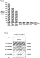
- Fig. 5 is a diagram for illustrating the emission intensity.
- Fig. 5 shows representative emission intensities of thermal power generation, solar power generation, wind power generation, nuclear power generation, geothermal power generation, and hydroelectric power generation.
- thermal power generation coal-fired power generation, oil-fired power generation, and liquefied natural gas (LNG) thermal power generation
- LNG liquefied natural gas
- the operator server 6 of the power company has the data related to the emission intensity of that electric power when generated. Accordingly, the emission intensity acquisition unit 302 can obtain from the operator server 6 the emission intensity of the amount of electric power supplied from the electric vehicle supply equipment 2 to the vehicle 1. The obtained emission intensity is output to the power coloring unit 304.
- the consumption acquisition unit 303 obtains from the vehicle 1 the amount of electric power consumed (used) from the battery 11 while the vehicle 1 is traveling. The obtained amount of electric power is output to the power coloring unit 304.
- the power coloring unit 304 Based on the amount of electric power charged to the battery 11 and the amount of electric power consumed from the battery 11, the power coloring unit 304 performs the power coloring process on the amount of electric power stored in the battery 11.
- Fig. 6 is a conceptual diagram of the power coloring process.
- the server 3 associates the amount of electric power charged to the battery 11 with its emission intensity when that electric power is generated.
- the server 3 distinctly manages the association between the amount of electric power charged to the battery 11 and the emission intensity for each external charging opportunity.
- Fig. 6 illustrates a result of the power coloring process when external charging is performed four times.
- the server 3 associates an amount of electric power P1 charged to the battery 11 with an emission intensity E1.
- the server 3 associates an amount of electric power P2 charged to the battery 11 with an emission intensity E2. The same applies to the third charging opportunity and the fourth charging opportunity.
- Fig. 7 is a conceptual diagram for illustrating the power coloring process according to the present embodiment.
- the four charging opportunities which are the first charging opportunity, the third charging opportunity, the second charging opportunity, the fourth charging opportunity, are listed in order starting from the smallest emission intensity to the largest emission intensity (E1 ⁇ E3 ⁇ E2 ⁇ E4).
- a regulatory limit Ereg for the emission intensity at which the vehicle 1 is permitted to travel within a green zone is defined by laws and regulations or policies.
- the emission intensities E1 and E3 at the first and third charging opportunities are less than the regulatory limit Ereg. Therefore, the amounts of electric powers P1 and P3 charged at the first and third charging opportunities are amounts of clean electric power.
- the emission intensities E2 and E4 at the second and fourth charging opportunities are greater than the regulatory limit Ereg (E1 ⁇ E3 ⁇ Ereg ⁇ E2 ⁇ E4).
- the amounts of electric power P2 and P4 charged at the second and fourth charging opportunities are not amounts of clean electric power.
- the server 3 regards that the amounts of clean electric power charged to the battery 11 at the first and third charging opportunities are to be consumed if the vehicle 1 stays within the green zone. Accordingly, comparing before and after the vehicle 1 travels in the green zone, the amounts of clean electric power (PI + P3) charged to the battery 11 at the first and third charging opportunities are used and decrease, as shown in Fig. 7 . The amounts of electric power (P2 + P4) charged to the battery 11 at the second and fourth charging opportunities remain unused.
- the server 3 (the travel permission unit 309) permits the vehicle 1 to enter or travel within the green zone. In contrast, if the amounts of clean electric power (PI + P3) are less than or equal to the reference amount Pref, the server 3 does not permit (disallows) the entry of the vehicle 1 into the green zone.
- the server 3 requests the vehicle 1 to promptly leave the green zone.
- the EV-range calculation unit 305 calculates a distance (an EV range) the vehicle 1 can travel in the EV mode within the green zone. More specifically, as the EV range, the EV-range calculation unit 305 can calculate a distance that the vehicle 1 can travel, consuming the amounts of clean electric power (PI + P3 in the examples of Figs. 6 and 7 ) within the amount of electric power stored in the battery 11.
- the power consumption efficiency of the vehicle 1 (a distance the vehicle 1 can travel per unit amount of electric power (unit: km/kWh), or an amount of electric power the vehicle 1 consumes to travel a unit distance (unit: kWh/km)) can be used for the calculation of the EV range.
- the power consumption efficiency of the vehicle 1 may be the actual value of the vehicle 1, or a catalogue value for the vehicle type of the vehicle 1.
- the vehicle 1 is notified of the EV range calculated by the EV-range calculation unit 305 by a communication module (not shown), and the EV range is displayed on the HMI 12.
- a message "traveling in green zone; OK” may be displayed on the HMI 12.
- a message "traveling in green zone; NG” may be displayed on the HMI 12. This allows the user of the vehicle outside the green zone to previously know whether the entry of the vehicle 1 into the green zone is to be permitted. The user is also allowed to know how far the vehicle 1 can travel within the green zone. If the vehicle 1 already stays in the green zone, the user is allowed to know a remaining distance the vehicle 1 can travel within the green zone.
- the vehicle location acquisition unit 306 obtains the location information (GPS the information) of the vehicle 1 from the vehicle 1. The obtained location information is output to the location determination unit 308.
- the map storage unit 307 stores map information on a geographical region covered by the power management system 100.
- the geographical region covers at least one green zone.
- the map information is output to the location determination unit 308.
- the location determination unit 308 compares the location information of the vehicle 1 with the map information, thereby determining whether the vehicle 1 is located inside or outside the green zone.
- the location determination unit 308 may also calculate a distance from the vehicle 1 to the boundary of the green zone, and determine that the vehicle 1 is approaching the green zone if the distance is below a predetermined value.
- a result of the determination by the location determination unit 308 is output to the travel permission unit 309.
- the travel permission unit 309 determines whether to permit or not permit the vehicle 1 to travel (or continue to travel) within the green zone, based on a result of the power coloring process. Since this determination approach has been described with respect to Figs. 6 and 7 , the description will not be repeated. The vehicle 1 is notified of whether the vehicle 1 is permitted/not permitted to travel within the green zone.
- the administrator (regulatory body) 8 of the green zone is also notified of whether the vehicle 1 is permitted/not permitted to travel in the green zone, together with the identification information (e.g., the number on the number plate) of the vehicle 1.
- the identification information e.g., the number on the number plate
- Fig. 8 is a flowchart illustrating the green zone management process.
- the green zone management process is performed each time predetermined conditions are met or each time a predetermined time period elapses.
- Each process step described in Fig. 8 and the flowchart of Fig. 9 described later is implemented by software processing by the server 3. However, each process step may be implemented by hardware (an electric circuit) disposed in the server 3.
- each process step is abbreviated as S. For ease of understanding, assume that the vehicle 1 is outside the green zone at the start of the process.
- the server 3 determines whether the vehicle 1 is approaching the green zone. If the vehicle 1 is distant from the green zone (NO in S1), the subsequent processes are skipped. If the vehicle 1 approaches the green zone (YES in S1), the server 3 passes the process to S2.
- the server 3 determines whether the amount of electric power stored in the battery 11 includes the amount of clean electric power, having an emission intensity less than or equal to the regulatory limit Ereg, is greater than a predetermined reference amount Pref.
- the amount of clean electric power is calculated by the power coloring process described later.
- a most comprehensible example of the reference amount Pref is zero.
- the reference amount Pref may be a value greater than zero. The value can be determined based on, for example, the amount of electric power that is consumed by a typical vehicle when traveling a predetermined distance in the EV mode. If the amount of clean electric power is less than or equal to the reference amount Pref (NO in S2), the server 3 does not permit the entry of the vehicle 1 to the green zone (S3). In contrast, if the amount of clean electric power is greater than the reference amount Pref (YES in S2), the server 3 permits the entry of the vehicle 1 to the green zone (S4). Assume that this results in the vehicle 1 having entered the green zone.
- the server 3 determines whether a predetermine time (e.g., a few seconds to a few minutes) has elapsed since the previous execution of the process steps of S5 to S8. If the predetermine time has elapsed (YES in S5), the server 3 passes the process to S6.
- a predetermine time e.g., a few seconds to a few minutes
- the server 3 determines whether the amount of electric power stored in the battery 11 includes an amount of clean electric power greater than the reference amount Pref.
- the reference amount Pref presented in the process step of S2 and the reference amount Pref presented in the process step of S6 may be the same, or different values may be set. More specifically, since the amount of clean electric power gradually decreases as the vehicle 1 travels, if the amount of clean electric power is not sufficient at a moment the vehicle 1 enters the green zone, the amount of clean electric power is highly likely to be depleted while the vehicle 1 is staying in the green zone. Accordingly, the reference amount Pref presented in the process step of S2 may be a value within a certain margin relative to the reference amount Pref in the process step of S6.
- the server 3 If the amount of clean electric power is greater than the reference amount Pref (YES in S6), the server 3 permits the vehicle 1 to travel within the green zone (S7). Then, the server 3 determines whether the vehicle 1 is still staying within the green zone (S8). If the vehicle 1 is staying in the green zone (YES in S8), the server 3 returns the process to S5. This repeats the process steps of S5 to S8 while the vehicle 1 is staying within the green zone. If the vehicle 1 leaves the green zone (NO in S8), the server 3 ends the series of process steps.
- the server 3 In S6, if the amount of clean electric power is less than or equal to the reference amount Pref (NO in S6), the server 3 notifies the vehicle 1 that the vehicle 1 should leave the green zone (S9). The server 3 may send the vehicle 1 a warning prompting the vehicle 1 to leave the green zone. If the vehicle 1 having received a notice or a warning does not leave the green zone promptly (NO in S10), the server 3 may repeat a notice or a warning.
- the server 3 may transmit the identification information and the location information of the vehicle 1 to the administrator 8 of the green zone. This allows the administrator 8 to identify the vehicle 1 and strongly warn or impose a penalty, such as a fine, on the user of the vehicle 1. If the vehicle 1 leaves the green zone (YES in S10), the server 3 ends the series of process steps.
- a prescribed period of time e.g., a few hours
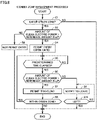
- Fig. 9 is a flowchart illustrating one example of the power coloring process according to Embodiment 1.
- the power coloring process is repeatedly performed at predetermined intervals.
- the server 3 determines whether the vehicle 1 has performed external charging at the electric vehicle supply equipment 2. If the vehicle 1 has performed external charging (YES in S101), the server 3 obtains the amount of electric power charged from the electric vehicle supply equipment 2 to the vehicle 1, through communications with the electric vehicle supply equipment 2 (or the vehicle 1) (S102). Regarding the amount of electric power supplied from the power system 4 to the electric vehicle supply equipment 2, the server 3 further obtains, through communications with the operator server 6, the data related to the emission intensity of that amount of electric power when generated (S103).
- the server 3 associates the amount of electric power obtained in S101 and the emission intensity obtained in S102 for each external charging opportunity of the vehicle 1, and stores the association into the memory 32. This allows the server 3 to distinctly manage the association between the amount of electric power charged to the battery 11 and the emission intensity for each external charging opportunity.
- the server 3 obtains from the vehicle 1 the amount of electric power consumed from the amount of electric power stored in the battery 11 (S105).
- the server 3 subtracts the amount of electric power obtained in S105 from the amount of electric power stored in the battery 11, thereby updating the association between the amount of electric power stored in the battery 11 and the emission intensity.
- This computation approach is not particularly limited. Various approaches can be adopted. For example, in the example shown in Fig. 7 , the consumed amount of electric power is withdrawn from P3 having a greater emission intensity among the amounts of clean electric power (PI + P3) before the vehicle 1 travels in the green zone. However, the consumed amount of electric power may be withdrawn from P3 having a less emission intensity. Alternatively, the consumed amount of electric power may be withdrawn from the amount of clean electric power (P1 + P3) while keeping the ratio of P1 to P3. After the execution of the process step S104 or S106, the process proceeds to S107.
- the server 3 calculates the most-recent value of the amount of clean electric power within the amount of electric power stored in the battery 11. Then, the server 3 notifies the vehicle 1 of the most-recent value of the amount of clean electric power in terms of EV range of the vehicle 1 (S108). However, the server 3 may notify the vehicle 1 of the amount of clean electric power as is.
- Fig. 10 is a diagram showing one example of the green zone information displayed on the HMI 12 (the instrument panel 121) of the vehicle 1 having received a notification.
- the information as to whether the vehicle 1 is permitted to travel in the green zone (or enter the green zone), an amount of electric power that the vehicle 1 can use to travel in the green zone (an amount of green electric power), and an EV range that the vehicle 1 can travel in the green zone can be displayed on the instrument panel 121.
- the green zone information displayed on the instrument panel 121 may contain any one or two of these three information items.
- the server 3 performs the power coloring process on the amount of electric power stored in the battery 11, and associates the amount of electric power stored in the battery 11 with emission intensities. This allows the server 3 to know how much clean electric power is included in the amount of electric power stored in the battery 11. Thus, according to the present embodiment, the server 3 can distinctly separate and appropriately manage vehicles that are permitted to enter and travel in the green zone and those that are not.
- Figs. 8 and 9 have been described with reference to the server 3 performing all the steps. However, the steps may be performed by the ECU 13 of the vehicle 1. Alternatively, the steps may be divided between the server 3 and the ECU 13. In other words, the server 3 may perform some of the steps and the ECU 13 may perform the rest.
Landscapes
- Engineering & Computer Science (AREA)
- Business, Economics & Management (AREA)
- Transportation (AREA)
- Mechanical Engineering (AREA)
- Chemical & Material Sciences (AREA)
- Combustion & Propulsion (AREA)
- Power Engineering (AREA)
- Human Resources & Organizations (AREA)
- Economics (AREA)
- Strategic Management (AREA)
- General Physics & Mathematics (AREA)
- Physics & Mathematics (AREA)
- Development Economics (AREA)
- General Business, Economics & Management (AREA)
- Marketing (AREA)
- Theoretical Computer Science (AREA)
- Tourism & Hospitality (AREA)
- Health & Medical Sciences (AREA)
- Entrepreneurship & Innovation (AREA)
- Primary Health Care (AREA)
- General Health & Medical Sciences (AREA)
- Game Theory and Decision Science (AREA)
- Educational Administration (AREA)
- Life Sciences & Earth Sciences (AREA)
- Accounting & Taxation (AREA)
- Finance (AREA)
- Operations Research (AREA)
- Sustainable Energy (AREA)
- Sustainable Development (AREA)
- Quality & Reliability (AREA)
- Emergency Management (AREA)
- Water Supply & Treatment (AREA)
- Public Health (AREA)
- Electric Propulsion And Braking For Vehicles (AREA)
- Charge And Discharge Circuits For Batteries Or The Like (AREA)
- Hybrid Electric Vehicles (AREA)
- Traffic Control Systems (AREA)
Abstract
A green zone exists in which traveling of a vehicle (1) using an amount of electric power that has a greenhouse gas emission intensity greater than a regulatory limit is restricted. A server (3) includes: I/O ports (33) through which the emission intensity of the electric power supplied from an electric vehicle supply equipment (2) is obtained; and a processor (31) that associates the amount of electric power charged from the electric vehicle supply equipment (2) to a battery (11) with the emission intensity obtained through the I/O ports (33). The processor (31): determines, based on an amount of electric power having an emission intensity less than the regulatory limit within the amount of electric power stored in the battery (11), whether a vehicle (1) should be permitted to travel in the green zone; and notifies a user of the vehicle (1) of a determination result.
Description
- This nonprovisional application is based on
Japanese Patent Application No. 2021-041175 filed on March 15, 2021 - The present disclosure relates to a server, a power management system, and a power management method, and, more particularly, to a technique for managing electric power information of a vehicle.
- The amount of electric power stored in the traction battery of a vehicle include those derived from various power generation modes, such as thermal power generation, nuclear power generation, hydroelectric power generation, solar power generation, etc. A management approach is known for differentiating the amounts of electric power stored in a battery by power generation mode (or by amount of greenhouse gas produced upon generation of power) (e.g., see
Japanese Patent Laying-Open No. 2020-86911 - An area may be set by laws and regulations or policies where reduction in emission of the exhaust gas is demanded or emission of the exhaust gas is not permitted. Such an area is called "green zone" or "zero emission vehicle (ZEV) zone" (e.g., see
Japanese Patent Laying-Open No. 2019-85094 - At present, it is common that a vehicle is permitted to travel within the green zone if the vehicle travels in an electric vehicle (EV) mode (electric power-consuming traveling, without driving the engine). However, the present inventors have focused on a fact that the following problem can occur in the future.
- In the future, electric vehicles and plug-in hybrid vehicles are expected to be widely used. In contrast, a respective country may further raise the set goal for the reduction of greenhouse gas emission. To this end, as a condition for permitting the vehicle to travel within the green zone, the vehicle may be asked how much greenhouse gas the vehicle produces when generating the amount of electric power stored in the battery. As a result, whether the vehicle should be permitted to travel in the green zone cannot be managed just by determining whether the vehicle can travel in the EV mode.
- The present disclosure is made in view of the problem above, and an object of the present disclosure is to appropriately manage a vehicle that travels in a zone restricted with respect to the amount of production of greenhouse gas involved in generation of power used by the vehicle.
- (1) A server according to a first aspect of the present disclosure manages electric power information of a vehicle. The vehicle includes a power storage device that is charged with electric power supplied from a charging facility. The server includes: an interface that obtains an emission intensity of greenhouse gas of electric power supplied from the charging facility; and a processor that associates an amount of electric power charged from the charging facility to the power storage device with the emission intensity obtained via the interface. The processor: determines, based on an amount of electric power having the emission intensity less than a regulatory limit within an amount of electric power stored in the power storage device, whether to permit the vehicle to travel within a travel restriction zone in which traveling using an amount of electric power having the emission intensity greater than the regulatory limit is restricted; and notifies a user of the vehicle of a determination result.
- (2) The processor: notifies the user of the vehicle as being permitted to travel in the travel restriction zone, when the amount of electric power having the emission intensity less than the regulatory limit is greater than a reference amount; and notifies the user of the vehicle as being not permitted to travel in the travel restriction zone, when the amount of electric power having the emission intensity less than the regulatory limit is less than the reference amount.
- In the configurations (1) and (2) above, the processor manages the amount of electric power associated with the emission intensity (power coloring), which is charged from the charging facility to the power storage device. This allows the server to know how much electric power (clean electric power) having the emission intensity less than the regulatory limit is within the amount of electric power stored in the power storage device. Thus, according to the configurations (1) and (2) above, the vehicle that travels in the travel restriction zone can be appropriately managed.
- (3) Prior to the vehicle entering the travel restriction zone, the processor notifies the user of the determination result.
- In the configuration (3) above, prior to the vehicle entering the travel restriction zone, the user is notified of the determination result. This can, for example, prevent a situation in which the user knows that the entry into the travel restriction zone is not permitted immediately before attempting to do so, making the user confused. This also enables the user to take an appropriate action, such as selecting a route bypassing the travel restriction zone.
- (4) A power management system according to a second aspect of the present disclosure includes the server and the vehicle. The vehicle includes a display. The display shows the determination result in a manner viewable from inside the vehicle.
- (5) The display further shows at least one of the amount of electric power having the emission intensity less than the regulatory limit (an amount of clean electric power) and a distance that the vehicle (1) is allowed to travel using the amount of electric power (an EV range).
- In the configurations (4) and (5) above, a result of determination by the server (the
vehicle 1 is permitted/not permitted to travel in the green zone) or the conditions of the vehicle related to the amount of clean electric power or the EV range is displayed on the display. Thus, according to the configurations (4) and (5) above, the user of the vehicle is allowed to readily know the determination result or the conditions of the vehicle. - (6) A power management system according to a third aspect of the present disclosure includes the server and the vehicle. The vehicle includes a display. The display shows the determination result in a manner viewable from outside the vehicle.
- According to the configuration (6) above, one (such as an administrator of the travel restriction zone) can readily know, from outside the vehicle, whether the vehicle is permitted to enter or travel within the travel restriction zone, and he/she is thereby enabled to take an appropriate action (such as controlling vehicles not permitted to travel in the travel restriction zone).
- (7) The power management system further includes a gate disposed at a boundary of the travel restriction zone. As the vehicle approaches the gate, the gate opens or closes depending on the amount of electric power having the emission intensity less than the regulatory limit (an amount of clean electric power).
- According to the configuration (7) above, the gate can be kept closed to vehicles that are short of an amount of clean electric power, preventing them to entering the green zone.
- (8) A power management method according to a fourth aspect of the present disclosure manages electric power information of a vehicle. The vehicle includes a power storage device that is charged with electric power supplied from a charging facility. The power management method includes a first step, a second step, a third step, and a fourth step. The first step is obtaining the amount of electric power charged from the charging facility to the power storage device. The second step is obtaining an emission intensity of greenhouse gas of the electric power supplied from the charging facility. The third step is associating the amount of electric power charged from the charging facility to the power storage device with the emission intensity. The fourth step is determining, based on an amount of electric power having the emission intensity less than a regulatory limit within an amount of electric power stored in the power storage device, whether to permit the vehicle to travel within a travel restriction zone in which traveling using an amount of electric power having the emission intensity greater than the regulatory limit is restricted, and notifying a user of the vehicle of a determination result.
- According to the method (8) above, the vehicle that travels in the travel restriction zone can be appropriately managed, as with the configuration (1) above.
- The foregoing and other objects, features, aspects and advantages of the present disclosure will become more apparent from the following detailed description of the present disclosure when taken in conjunction with the accompanying drawings.
-
-
Fig. 1 is a schematic configuration of a power management system according to an embodiment of the present disclosure. -
Fig. 2 is a diagram for illustrating one example of how a vehicle enters or leaves a green zone. -
Fig. 3 is a diagram showing a configuration example of a human machine interface (HMI). -
Fig. 4 is a functional block diagram of a server. -
Fig. 5 is a diagram for illustrating emission intensity. -
Fig. 6 is a conceptual diagram of a power coloring process. -
Fig. 7 is a conceptual diagram for illustrating a power coloring process according to the present embodiment. -
Fig. 8 is a flowchart illustrating a green zone management process. -
Fig. 9 is a flowchart showing one example of the power coloring process. -
Fig. 10 is a diagram showing one example of green zone information displayed on the HMI (an instrument panel) of a notified vehicle. - Hereinafter, embodiments of the present disclosure will be now described in detail, with reference to the accompanying drawings. Note that the same reference sign is used to refer to the same or like parts, and the description thereof will not be repeated.
-
Fig. 1 is a schematic configuration of a power management system according to an embodiment of the present disclosure. Apower management system 100 includes avehicle 1; an electric vehicle supply equipment (EVSE) 2; aserver 3; apower system 4; apower transmission line 5; anoperator server 6; and a gate (seeFig. 2 ). - The
vehicle 1 is an electric-powered vehicle, and, more specifically, is a battery electric vehicle (BEV), a plug-in hybrid electric vehicle (PHEV), etc. Hereinafter, for simplicity, assume that thevehicle 1 is a BEV. Thevehicle 1 includes abattery 11, a human machine interface (HMI) 12, and an electronic control unit (ECU) 13. - The
battery 11 is an assembled battery formed of multiple cells (not shown). Each cell is a secondary battery, such as a lithium-ion battery or a nickel-hydrogen battery. Thebattery 11 supplies an electric power for generating a driving force for thevehicle 1. Thebattery 11 also stores electric power that is generated by a motor generator (not shown) upon braking through a regenerative braking system ofvehicle 1. Note that a capacitor, such as an electric double layer capacitor, can be employed, instead of thebattery 11. Thebattery 11 corresponds to a "power storage device" according to the present disclosure. - The
vehicle 1 has a configuration in which electric power supplied from the electricvehicle supply equipment 2 is charged to thebattery 11 as a charging cable, extending from the electricvehicle supply equipment 2, is connected to an inlet (not shown) of thevehicle 1. Hereinafter, this mode of charging is also referred to as "external charging." - For example, the
HMI 12 receives operations by a user (a driver), or provides the user with various information and data. The configuration of theHMI 12 will be described in more detail, with reference toFig. 3 . - The
ECU 13 includes a processor, such as a central processing unit (CPU), a memory, such as a read only memory (ROM) and a random access memory (RAM), and input/output ports. TheECU 13 executes various arithmetic processes for controlling thevehicle 1. - The electric
vehicle supply equipment 2 is, for example, a public charging station or a home charger. The electricvehicle supply equipment 2 receives electric power from thepower system 4 via thepower transmission line 5, and supplies the electric power to thevehicle 1. The electricvehicle supply equipment 2 and theserver 3 are also capable of two-way communications therebetween. - The
server 3 is a computer which manages thevehicle 1 and the electricvehicle supply equipment 2 within thepower management system 100. Theserver 3 includes aprocessor 31, amemory 32, and input/output ports 33. Theprocessor 31 is, for example, a central processing unit (CPU), and executes the arithmetic processes written in programs. Thememory 32 includes a memory storing the programs for execution by theprocessor 31, and stores various data (maps, relational expressions, parameters, etc.) that are used in the programs. Thememory 32 also includes a database, and stores data related to electric power for the various devices within thepower management system 100. The input/output ports 33 receive/output notifications, commands, requests, etc. from/to outside theserver 3. Theserver 3 includes a communication module (not shown), and communicates external to the power management system 100 (such as the operator server 6), in addition to thevehicle 1 and the electricvehicle supply equipment 2. - Examples of main processes performed by the
server 3 according to the present embodiment include "green zone management process" and "power coloring process." The green zone management process manages thevehicle 1 when entering the green zone and when traveling within the green zone. The power coloring process colors amounts of electric power stored in thebattery 11. These processes will be described in detail later. - The
power system 4 is a power network built by power plants and power transmission and distribution equipment (T&D) facilities. In the present embodiment, an electric power company serves as a power generation utility and a power T&D utility. The electric power company corresponds to a general power T&D utility and an administrator of thepower system 4, and maintains and manages thepower system 4. - The
operator server 6 belongs to the power company. Theoperator server 6 is a computer which manages the demand and supply of electric power supplied from thepower system 4. Theoperator server 6 has data as to how much greenhouse gas is produced at the power plant (the emission intensity). Theoperator server 6 is also capable of two-way communications with theserver 3. - Note that the number of
vehicles 1 and the electricvehicle supply equipment 2 included in thepower management system 100 is not particularly limited. The example shown inFig. 1 showmultiple vehicles 1 and multiple electric vehicle supply equipment. However, only onevehicle 1 and one electricvehicle supply equipment 2 may be included. -
Fig. 2 is a diagram for illustrating one example of how thevehicle 1 enters or leaves a green zone. Since emission of the exhaust gas is not permitted within the green zone, thevehicle 1 is requested to travel in the EV mode within the green zone. Note that the green zone corresponds to a "travel restriction zone" according to the present disclosure. - In the example shown in
Fig. 2 , agate 7 is provided at the boundary between inner side and outer side of the green zone. As thevehicle 1 approaches thegate 7, theserver 3 determines whether to permit thevehicle 1 to enter the green zone. If thevehicle 1 meets a predetermined condition (described later), theserver 3 permits thevehicle 1 to enter the green zone, and opens thegate 7. In contrast, if thevehicle 1 fails to meet the condition above, theserver 3 does not permit thevehicle 1 to enter the green zone, keeping thegate 7 closed. - However, the
gate 7 provided at the boundary is merely by way of example for clarity. A geofence (a virtual boundary) may be set, instead of a physical gate. If the geofence is set, a vehicle failing to meet the condition above may be subjected to penalty (e.g., a fine) if the vehicle enters the green zone. -
Fig. 3 is a diagram showing a configuration example of theHMI 12. In the present embodiment, theHMI 12 shows information for use by thevehicle 1 to travel in the green zone. In the following, the information will also be referred to as "green zone information." More specifically, the green zone information contains information as to whether thevehicle 1 should be permitted or not permitted to enter or travel within the green zone. TheHMI 12 includes aninstrument panel 121, a headup display (HUD) 122, anavigation screen 123, and anindicator lamp 124. - The
instrument panel 121 is a dashboard in which meters are installed, and displays various states ofvehicle 1, according to control by theECU 13. Theinstrument panel 121 displays the speedometer, the tripmeter, the SOC of thebattery 11, idiot lights, etc., and also displays the green zone information. Note that a multiinformation display (MID) can be employed, instead of theinstrument panel 121. - The
HUD 122 projects various pieces of information in front of the driver's field of view as a virtual image. Specifically, theHUD 122 displays the vehicle speed of thevehicle 1, the direction of travel to the destination, traffic signs, etc. The green zone information may be displayed on theHUD 122. - The
navigation screen 123 is a display of a navigation system (not shown). The navigation system includes a GPS receiver for locating thevehicle 1 based on a radio wave from an artificial satellite (not shown). The navigation system displays, on thenavigation screen 123, the current location ofvehicle 1 and a recommended route to the destination ofvehicle 1, based on GPS data of thevehicle 1 and road map data. Thenavigation screen 123 may be a touch screen monitor (not shown). The green zone information can be displayed also on thenavigation screen 123. - In this example, the
indicator lamp 124 is disposed on the dashboard. Theindicator lamp 124 may be disposed at a different location, such as at the rear-view mirror, a side-view mirror, or the like. Theindicator lamp 124 is switchable between two or more lighting colors. As one example, theindicator lamp 124 showing green light indicates that thevehicle 1 is permitted to travel within the green zone (permitted to enter the green zone). Theindicator lamp 124 showing red light, on the other hand, indicates that thevehicle 1 is not permitted to travel within the green zone (not permitted to enter the green zone). The green zone information described above may be represented by theindicator lamp 124 being turned on/off. - The
instrument panel 121, theHUD 122, and thenavigation screen 123 are basically viewable from inside the vehicle 1 (inside the vehicle compartment). In contrast, theindicator lamp 124 is disposed at a location viewable from both inside and outside thevehicle 1. Accordingly, a person other than the user of the vehicle 1 (an administrator of the green zone described later) can also visually recognize theindicator lamp 124 to confirm the green zone information of thevehicle 1. - At least one of the
instrument panel 121, theHUD 122, thenavigation screen 123, and theindicator lamp 124 of thevehicle 1 corresponds to a "display" according to the present disclosure. For ease of description, an example will be described below in which the green zone information is shown on theinstrument panel 121. However, a device on which the green zone information is displayed is not limited to one mounted on thevehicle 1, and may be a user's mobile phone (smartphone, etc.). In other words, "notify a user of thevehicle 1" can include notifying a user's mobile terminal. - If electric power generated by burning a fossil fuel is charged to the
battery 11, no greenhouse gas is produced while thevehicle 1 is traveling in the EV mode. However, a certain level of greenhouse gas is produced when considering through the course from the generation of electric power to the consumption thereof. Accordingly, just requesting thevehicle 1 to travel in the EV mode within the green zone does not contribute to reduction of greenhouse gas emission, which may result in failing to achieve a high goal for the reduction of greenhouse gas emission. - Thus, in the present embodiment, how much greenhouse gas is produced when the amount of electric power stored in the
battery 11 is generated is considered as a condition for permitting thevehicle 1 to enter or travel within the green zone. More specifically, "emission intensity" (unit: g/kWh) which is greenhouse gas emission per unit of generated power is taken into account. - During the external charging of the
vehicle 1, theserver 3 obtains data related to the emission intensity from the power company, and associates the amount of electric power stored in thebattery 11 with the emission intensity. Stated differently, theserver 3 performs "power coloring process," in which the amount of electric power stored in thebattery 11 is conceptually colored in accordance with the emission intensity. This enables theserver 3 to quantitatively evaluate the amount of electric power stored in thebattery 11 based on whether an amount of electric power is clean or not. - The
server 3 permits thevehicle 1 to travel in the green zone, consuming the amount of clean electric power having an emission intensity less than the regulatory limit (described as Ereg). Hereinafter, for simplicity, this amount of electric power will also be referred to as an "amount of clean electric power." If the amount of clean electric power of thevehicle 1 is greater than a predetermined reference amount Pref, theserver 3 permits thevehicle 1 to enter and travel in the green zone. If the amount of clean electric power is less than or equal to the reference amount Pref, in contrast, theserver 3 does not permit thevehicle 1 to enter the green zone. Even after thevehicle 1 has entered the green zone, theserver 3 does not permit thevehicle 1 to travel within the green zone any further if the amount of clean electric power is consumed and depleted along with thevehicle 1 traveling within the green zone. This process will be described in detail later. -
Fig. 4 is a functional block diagram of theserver 3. Theserver 3 includes a chargeamount acquisition unit 301, an emissionintensity acquisition unit 302, aconsumption acquisition unit 303, apower coloring unit 304, an EV-range calculation unit 305, a vehiclelocation acquisition unit 306, amap storage unit 307, alocation determination unit 308, and atravel permission unit 309. - During the external charging of the
vehicle 1, the chargeamount acquisition unit 301 obtains the amount of electric power that is supplied from the electricvehicle supply equipment 2 to thevehicle 1 and charged to thebattery 11. While the chargeamount acquisition unit 301 can obtain the amount of electric power charged to thebattery 11, through communications with the electricvehicle supply equipment 2, the chargeamount acquisition unit 301 may obtain this from thevehicle 1. The obtained amount of electric power is output to thepower coloring unit 304. - The emission
intensity acquisition unit 302 obtains from the power company the emission intensity of the amount of electric power supplied from the electricvehicle supply equipment 2 to thevehicle 1. -
Fig. 5 is a diagram for illustrating the emission intensity.Fig. 5 shows representative emission intensities of thermal power generation, solar power generation, wind power generation, nuclear power generation, geothermal power generation, and hydroelectric power generation. One can see, fromFig. 5 , that thermal power generation (coal-fired power generation, oil-fired power generation, and liquefied natural gas (LNG) thermal power generation) have greater emission intensities than the other power generation modes. - Returning to
Fig. 4 , regarding the electric power transmitted from thepower system 4 to the electricvehicle supply equipment 2 via thepower transmission line 5, theoperator server 6 of the power company has the data related to the emission intensity of that electric power when generated. Accordingly, the emissionintensity acquisition unit 302 can obtain from theoperator server 6 the emission intensity of the amount of electric power supplied from the electricvehicle supply equipment 2 to thevehicle 1. The obtained emission intensity is output to thepower coloring unit 304. - The
consumption acquisition unit 303 obtains from thevehicle 1 the amount of electric power consumed (used) from thebattery 11 while thevehicle 1 is traveling. The obtained amount of electric power is output to thepower coloring unit 304. - Based on the amount of electric power charged to the
battery 11 and the amount of electric power consumed from thebattery 11, thepower coloring unit 304 performs the power coloring process on the amount of electric power stored in thebattery 11. -
Fig. 6 is a conceptual diagram of the power coloring process. Theserver 3 associates the amount of electric power charged to thebattery 11 with its emission intensity when that electric power is generated. In the present embodiment, theserver 3 distinctly manages the association between the amount of electric power charged to thebattery 11 and the emission intensity for each external charging opportunity. -
Fig. 6 illustrates a result of the power coloring process when external charging is performed four times. For the first charging opportunity, theserver 3 associates an amount of electric power P1 charged to thebattery 11 with an emission intensity E1. For the second charging opportunity, theserver 3 associates an amount of electric power P2 charged to thebattery 11 with an emission intensity E2. The same applies to the third charging opportunity and the fourth charging opportunity. -
Fig. 7 is a conceptual diagram for illustrating the power coloring process according to the present embodiment. In this example, the four charging opportunities, which are the first charging opportunity, the third charging opportunity, the second charging opportunity, the fourth charging opportunity, are listed in order starting from the smallest emission intensity to the largest emission intensity (E1 < E3 < E2 < E4). A regulatory limit Ereg for the emission intensity at which thevehicle 1 is permitted to travel within a green zone is defined by laws and regulations or policies. Among the emission intensities E1 to E4 at the four charging opportunities, the emission intensities E1 and E3 at the first and third charging opportunities are less than the regulatory limit Ereg. Therefore, the amounts of electric powers P1 and P3 charged at the first and third charging opportunities are amounts of clean electric power. In contrast, the emission intensities E2 and E4 at the second and fourth charging opportunities are greater than the regulatory limit Ereg (E1 < E3 < Ereg < E2 < E4). The amounts of electric power P2 and P4 charged at the second and fourth charging opportunities are not amounts of clean electric power. - The
server 3 regards that the amounts of clean electric power charged to thebattery 11 at the first and third charging opportunities are to be consumed if thevehicle 1 stays within the green zone. Accordingly, comparing before and after thevehicle 1 travels in the green zone, the amounts of clean electric power (PI + P3) charged to thebattery 11 at the first and third charging opportunities are used and decrease, as shown inFig. 7 . The amounts of electric power (P2 + P4) charged to thebattery 11 at the second and fourth charging opportunities remain unused. - If the amounts of clean electric power (PI + P3) charged to the
battery 11 at the first and third charging opportunities are greater than a reference amount Pref, the server 3 (the travel permission unit 309) permits thevehicle 1 to enter or travel within the green zone. In contrast, if the amounts of clean electric power (PI + P3) are less than or equal to the reference amount Pref, theserver 3 does not permit (disallows) the entry of thevehicle 1 into the green zone. - Even though the amounts of clean electric power (PI + P3) are greater than the reference amount Pref at the time the
vehicle 1 enters the green zone, if the amounts of clean electric power (PI + P3) are less than or equal to the reference amount Pref while thevehicle 1 is traveling within the green zone, theserver 3 requests thevehicle 1 to promptly leave the green zone. - Referring, again, to
Fig. 4 , the EV-range calculation unit 305 calculates a distance (an EV range) thevehicle 1 can travel in the EV mode within the green zone. More specifically, as the EV range, the EV-range calculation unit 305 can calculate a distance that thevehicle 1 can travel, consuming the amounts of clean electric power (PI + P3 in the examples ofFigs. 6 and7 ) within the amount of electric power stored in thebattery 11. The power consumption efficiency of the vehicle 1 (a distance thevehicle 1 can travel per unit amount of electric power (unit: km/kWh), or an amount of electric power thevehicle 1 consumes to travel a unit distance (unit: kWh/km)) can be used for the calculation of the EV range. The power consumption efficiency of thevehicle 1 may be the actual value of thevehicle 1, or a catalogue value for the vehicle type of thevehicle 1. - The
vehicle 1 is notified of the EV range calculated by the EV-range calculation unit 305 by a communication module (not shown), and the EV range is displayed on theHMI 12. - Alternative to or in addition to the EV range, if the EV range is longer than the reference range (if the amount of clean electric power is greater than the reference amount Pref), a message "traveling in green zone; OK" may be displayed on the
HMI 12. In contrast, if the EV range is less than or equal to the reference range (if the amount of clean electric power is less than or equal to the reference amount Pref), a message "traveling in green zone; NG" may be displayed on theHMI 12. This allows the user of the vehicle outside the green zone to previously know whether the entry of thevehicle 1 into the green zone is to be permitted. The user is also allowed to know how far thevehicle 1 can travel within the green zone. If thevehicle 1 already stays in the green zone, the user is allowed to know a remaining distance thevehicle 1 can travel within the green zone. - The vehicle
location acquisition unit 306 obtains the location information (GPS the information) of thevehicle 1 from thevehicle 1. The obtained location information is output to thelocation determination unit 308. - The
map storage unit 307 stores map information on a geographical region covered by thepower management system 100. The geographical region covers at least one green zone. The map information is output to thelocation determination unit 308. - The
location determination unit 308 compares the location information of thevehicle 1 with the map information, thereby determining whether thevehicle 1 is located inside or outside the green zone. Thelocation determination unit 308 may also calculate a distance from thevehicle 1 to the boundary of the green zone, and determine that thevehicle 1 is approaching the green zone if the distance is below a predetermined value. A result of the determination by thelocation determination unit 308 is output to thetravel permission unit 309. - When the
vehicle 1 approaches the green zone or while thevehicle 1 is traveling within the green zone, thetravel permission unit 309 determines whether to permit or not permit thevehicle 1 to travel (or continue to travel) within the green zone, based on a result of the power coloring process. Since this determination approach has been described with respect toFigs. 6 and7 , the description will not be repeated. Thevehicle 1 is notified of whether thevehicle 1 is permitted/not permitted to travel within the green zone. - Preferably, the administrator (regulatory body) 8 of the green zone is also notified of whether the
vehicle 1 is permitted/not permitted to travel in the green zone, together with the identification information (e.g., the number on the number plate) of thevehicle 1. This allows the administrator to visually recognize theindicator lamp 124 and then crack down on or penalize the user of thevehicle 1 if thevehicle 1 is traveling within the green zone although thevehicle 1 is not permitted to do so. -
Fig. 8 is a flowchart illustrating the green zone management process. The green zone management process is performed each time predetermined conditions are met or each time a predetermined time period elapses. Each process step described inFig. 8 and the flowchart ofFig. 9 described later is implemented by software processing by theserver 3. However, each process step may be implemented by hardware (an electric circuit) disposed in theserver 3. Hereinafter, each process step is abbreviated as S. For ease of understanding, assume that thevehicle 1 is outside the green zone at the start of the process. - In S1, based on the location information of the
vehicle 1 and the map information, theserver 3 determines whether thevehicle 1 is approaching the green zone. If thevehicle 1 is distant from the green zone (NO in S1), the subsequent processes are skipped. If thevehicle 1 approaches the green zone (YES in S1), theserver 3 passes the process to S2. - In S2, the
server 3 determines whether the amount of electric power stored in thebattery 11 includes the amount of clean electric power, having an emission intensity less than or equal to the regulatory limit Ereg, is greater than a predetermined reference amount Pref. The amount of clean electric power is calculated by the power coloring process described later. A most comprehensible example of the reference amount Pref is zero. However, the reference amount Pref may be a value greater than zero. The value can be determined based on, for example, the amount of electric power that is consumed by a typical vehicle when traveling a predetermined distance in the EV mode. If the amount of clean electric power is less than or equal to the reference amount Pref (NO in S2), theserver 3 does not permit the entry of thevehicle 1 to the green zone (S3). In contrast, if the amount of clean electric power is greater than the reference amount Pref (YES in S2), theserver 3 permits the entry of thevehicle 1 to the green zone (S4). Assume that this results in thevehicle 1 having entered the green zone. - In S5, the
server 3 determines whether a predetermine time (e.g., a few seconds to a few minutes) has elapsed since the previous execution of the process steps of S5 to S8. If the predetermine time has elapsed (YES in S5), theserver 3 passes the process to S6. - In S6, the
server 3 determines whether the amount of electric power stored in thebattery 11 includes an amount of clean electric power greater than the reference amount Pref. The reference amount Pref presented in the process step of S2 and the reference amount Pref presented in the process step of S6 may be the same, or different values may be set. More specifically, since the amount of clean electric power gradually decreases as thevehicle 1 travels, if the amount of clean electric power is not sufficient at a moment thevehicle 1 enters the green zone, the amount of clean electric power is highly likely to be depleted while thevehicle 1 is staying in the green zone. Accordingly, the reference amount Pref presented in the process step of S2 may be a value within a certain margin relative to the reference amount Pref in the process step of S6. - If the amount of clean electric power is greater than the reference amount Pref (YES in S6), the
server 3 permits thevehicle 1 to travel within the green zone (S7). Then, theserver 3 determines whether thevehicle 1 is still staying within the green zone (S8). If thevehicle 1 is staying in the green zone (YES in S8), theserver 3 returns the process to S5. This repeats the process steps of S5 to S8 while thevehicle 1 is staying within the green zone. If thevehicle 1 leaves the green zone (NO in S8), theserver 3 ends the series of process steps. - In S6, if the amount of clean electric power is less than or equal to the reference amount Pref (NO in S6), the
server 3 notifies thevehicle 1 that thevehicle 1 should leave the green zone (S9). Theserver 3 may send the vehicle 1 a warning prompting thevehicle 1 to leave the green zone. If thevehicle 1 having received a notice or a warning does not leave the green zone promptly (NO in S10), theserver 3 may repeat a notice or a warning. - Although not shown, if a prescribed period of time (e.g., a few hours) has elapsed, without the
vehicle 1 leaving the green zone, theserver 3 may transmit the identification information and the location information of thevehicle 1 to theadministrator 8 of the green zone. This allows theadministrator 8 to identify thevehicle 1 and strongly warn or impose a penalty, such as a fine, on the user of thevehicle 1. If thevehicle 1 leaves the green zone (YES in S10), theserver 3 ends the series of process steps. -
Fig. 9 is a flowchart illustrating one example of the power coloring process according toEmbodiment 1. The power coloring process is repeatedly performed at predetermined intervals. - In S101, the
server 3 determines whether thevehicle 1 has performed external charging at the electricvehicle supply equipment 2. If thevehicle 1 has performed external charging (YES in S101), theserver 3 obtains the amount of electric power charged from the electricvehicle supply equipment 2 to thevehicle 1, through communications with the electric vehicle supply equipment 2 (or the vehicle 1) (S102). Regarding the amount of electric power supplied from thepower system 4 to the electricvehicle supply equipment 2, theserver 3 further obtains, through communications with theoperator server 6, the data related to the emission intensity of that amount of electric power when generated (S103). - In S104, the
server 3 associates the amount of electric power obtained in S101 and the emission intensity obtained in S102 for each external charging opportunity of thevehicle 1, and stores the association into thememory 32. This allows theserver 3 to distinctly manage the association between the amount of electric power charged to thebattery 11 and the emission intensity for each external charging opportunity. - In contrast, if the
vehicle 1 does not perform external charging (NO in S101), that is, if thevehicle 1 is in a condition in which the amount of electric power stored in thebattery 11 is being consumed, such as a condition in which thevehicle 1 is traveling, theserver 3 obtains from thevehicle 1 the amount of electric power consumed from the amount of electric power stored in the battery 11 (S105). - In S106, according to a predetermined computation approach, the
server 3 subtracts the amount of electric power obtained in S105 from the amount of electric power stored in thebattery 11, thereby updating the association between the amount of electric power stored in thebattery 11 and the emission intensity. This computation approach is not particularly limited. Various approaches can be adopted. For example, in the example shown inFig. 7 , the consumed amount of electric power is withdrawn from P3 having a greater emission intensity among the amounts of clean electric power (PI + P3) before thevehicle 1 travels in the green zone. However, the consumed amount of electric power may be withdrawn from P3 having a less emission intensity. Alternatively, the consumed amount of electric power may be withdrawn from the amount of clean electric power (P1 + P3) while keeping the ratio of P1 to P3. After the execution of the process step S104 or S106, the process proceeds to S107. - In S107, the
server 3 calculates the most-recent value of the amount of clean electric power within the amount of electric power stored in thebattery 11. Then, theserver 3 notifies thevehicle 1 of the most-recent value of the amount of clean electric power in terms of EV range of the vehicle 1 (S108). However, theserver 3 may notify thevehicle 1 of the amount of clean electric power as is. -
Fig. 10 is a diagram showing one example of the green zone information displayed on the HMI 12 (the instrument panel 121) of thevehicle 1 having received a notification. As shown inFig. 10 , the information as to whether thevehicle 1 is permitted to travel in the green zone (or enter the green zone), an amount of electric power that thevehicle 1 can use to travel in the green zone (an amount of green electric power), and an EV range that thevehicle 1 can travel in the green zone can be displayed on theinstrument panel 121. However, the green zone information displayed on theinstrument panel 121 may contain any one or two of these three information items. - As described above, in the present embodiment, the
server 3 performs the power coloring process on the amount of electric power stored in thebattery 11, and associates the amount of electric power stored in thebattery 11 with emission intensities. This allows theserver 3 to know how much clean electric power is included in the amount of electric power stored in thebattery 11. Thus, according to the present embodiment, theserver 3 can distinctly separate and appropriately manage vehicles that are permitted to enter and travel in the green zone and those that are not. - Note that
Figs. 8 and9 have been described with reference to theserver 3 performing all the steps. However, the steps may be performed by theECU 13 of thevehicle 1. Alternatively, the steps may be divided between theserver 3 and theECU 13. In other words, theserver 3 may perform some of the steps and theECU 13 may perform the rest. - Although the present disclosure has been described and illustrated in detail, it is clearly understood that the same is by way of illustration and example only and is not to be taken by way of limitation, the scope of the present disclosure being interpreted by the terms of the appended claims.
Claims (8)
- A server (3) for managing electric power information of a vehicle (1), whereinthe vehicle (1) includes a power storage device (11) that is charged with electric power supplied from a charging facility (2),the server (3) comprising:an interface (33) that obtains an emission intensity of greenhouse gas of electric power supplied from the charging facility (2); anda processor (31) that associates an amount of electric power charged from the charging facility (2) to the power storage device (11) with the emission intensity obtained via the interface (33), whereinthe processor (31):determines, based on an amount of electric power having the emission intensity less than a regulatory limit within an amount of electric power stored in the power storage device (11), whether to permit the vehicle (1) to travel within a travel restriction zone in which traveling using an amount of electric power having the emission intensity greater than the regulatory limit is restricted; andnotifies a user of the vehicle of a determination result.
- The server (3) according to claim 1, wherein
the processor (31):notifies the user of the vehicle as being permitted to travel in the travel restriction zone, when the amount of electric power having the emission intensity less than the regulatory limit is greater than a reference amount; andnotifies the user of the vehicle as being not permitted to travel in the travel restriction zone, when the amount of electric power having the emission intensity less than the regulatory limit is less than the reference amount. - The server (3) according to claim 1 or 2, wherein
prior to the vehicle (1) entering the travel restriction zone, the processor (31) notifies the user of the determination result. - A power management system (100), comprising:the server (3) according to any one of claims 1 to 3; andthe vehicle (1), whereinthe vehicle (1) includes a display (121 to 123), andthe display (121 to 123) shows the determination result in a manner viewable from inside the vehicle (1).
- The power management system (100) according to claim 4, wherein
the display (121 to 123) further shows at least one of the amount of electric power having the emission intensity less than the regulatory limit and a distance that the vehicle (1) is allowed to travel using the amount of electric power. - A power management system (100), comprising:the server (3) according to any one of claims 1 to 3; andthe vehicle (1), whereinthe vehicle (1) includes a display (124), andthe display (124) shows the determination result in a manner viewable from outside the vehicle (1).
- The power management system according to any one of claims 4 to 6, further comprisinga gate (7) disposed at a boundary of the travel restriction zone, whereinas the vehicle (1) approaches the gate (7), the gate (7) opens or closes depending on the amount of electric power having the emission intensity less than the regulatory limit.
- A method for managing electric power information of a vehicle (1), whereinthe vehicle (1) includes a power storage device (11) that is charged with electric power supplied from a charging facility (2),the method comprising:obtaining the amount of electric power charged from the charging facility (2) to the power storage device (11);obtaining an emission intensity of greenhouse gas of the electric power supplied from the charging facility (2);associating the amount of electric power charged from the charging facility (2) to the power storage device (11) with the emission intensity;determining, based on an amount of electric power having the emission intensity less than a regulatory limit within an amount of electric power stored in the power storage device (11), whether to permit the vehicle (1) to travel within a travel restriction zone in which traveling using an amount of electric power having the emission intensity greater than the regulatory limit is restricted; andnotifying a user of the vehicle of a determination result.
Applications Claiming Priority (1)
| Application Number | Priority Date | Filing Date | Title |
|---|---|---|---|
| JP2021041175A JP7528828B2 (en) | 2021-03-15 | 2021-03-15 | Server, power management system and power management method |
Publications (1)
| Publication Number | Publication Date |
|---|---|
| EP4059766A1 true EP4059766A1 (en) | 2022-09-21 |
Family
ID=80780651
Family Applications (1)
| Application Number | Title | Priority Date | Filing Date |
|---|---|---|---|
| EP22162105.5A Pending EP4059766A1 (en) | 2021-03-15 | 2022-03-15 | Server, power management system, and power management method |
Country Status (4)
| Country | Link |
|---|---|
| US (1) | US11749089B2 (en) |
| EP (1) | EP4059766A1 (en) |
| JP (1) | JP7528828B2 (en) |
| CN (1) | CN115085305A (en) |
Families Citing this family (2)
| Publication number | Priority date | Publication date | Assignee | Title |
|---|---|---|---|---|
| JP7528827B2 (en) | 2021-03-15 | 2024-08-06 | トヨタ自動車株式会社 | Server, vehicle and power management method |
| JP2025012277A (en) * | 2023-07-13 | 2025-01-24 | トヨタ自動車株式会社 | vehicle |
Citations (8)
| Publication number | Priority date | Publication date | Assignee | Title |
|---|---|---|---|---|
| JP2009262692A (en) * | 2008-04-23 | 2009-11-12 | Toyota Motor Corp | Display device of plug-in hybrid vehicle |
| JP2010239704A (en) * | 2009-03-30 | 2010-10-21 | Tokyo Electric Power Co Inc:The | Greenhouse gas emission calculation device, greenhouse gas emission calculation method, and charging system |
| JP2011191909A (en) * | 2010-03-12 | 2011-09-29 | Omron Corp | Environment management apparatus, program for controlling the same, system for giving currency value, and method for controlling environment management apparatus |
| WO2011132054A2 (en) * | 2010-04-20 | 2011-10-27 | Toyota Jidosha Kabushiki Kaisha | Charging apparatus and vehicle equipped with the charging apparatus |
| JP2017178075A (en) * | 2016-03-30 | 2017-10-05 | トヨタ自動車株式会社 | Hybrid car |
| JP2019085094A (en) | 2017-11-07 | 2019-06-06 | 現代自動車株式会社Hyundai Motor Company | Hybrid vehicle and heating control method for the same |
| JP2020086911A (en) | 2018-11-26 | 2020-06-04 | トヨタ自動車株式会社 | Information processing system |
| JP2021041175A (en) | 2015-05-05 | 2021-03-18 | ビジョニックス リミテッド | Method for calibrating phoropter wheel assembly of object phoropter incorporating wavefront analyzer |
Family Cites Families (11)
| Publication number | Priority date | Publication date | Assignee | Title |
|---|---|---|---|---|
| JP5078119B2 (en) * | 2005-12-06 | 2012-11-21 | トヨタ自動車株式会社 | Charger |
| JP4211860B2 (en) * | 2007-04-25 | 2009-01-21 | トヨタ自動車株式会社 | ELECTRIC VEHICLE CHARGE CONTROL DEVICE, ELECTRIC VEHICLE, ELECTRIC VEHICLE CHARGE CONTROL METHOD, AND COMPUTER-READABLE RECORDING MEDIUM CONTAINING PROGRAM FOR CAUSING COMPUTER TO EXECUTE THE CHARGE CONTROL |
| JP2009184636A (en) * | 2008-02-08 | 2009-08-20 | Fuji Heavy Ind Ltd | Hybrid vehicle notification device |
| JP5344895B2 (en) * | 2008-12-10 | 2013-11-20 | 矢崎総業株式会社 | Charge monitoring device |
| JP5393602B2 (en) | 2010-07-01 | 2014-01-22 | 株式会社日立製作所 | Power control method, program, and power control apparatus |
| JP4962604B2 (en) * | 2010-07-21 | 2012-06-27 | トヨタ自動車株式会社 | Control device for hybrid vehicle and hybrid vehicle including the same |
| JP2013025432A (en) | 2011-07-19 | 2013-02-04 | Toyota Motor Corp | Device for providing information on environmental load reduction |
| WO2015016192A1 (en) | 2013-07-31 | 2015-02-05 | 日本電気株式会社 | Power supply/demand adjustment system and power supply/demand adjustment method |
| JP7022925B2 (en) * | 2017-07-06 | 2022-02-21 | パナソニックIpマネジメント株式会社 | Display device and display method |
| US11041734B2 (en) * | 2019-03-07 | 2021-06-22 | Ford Global Technologies, Llc | Systems and methods for optimizing a travel route of a hybrid-electric vehicle inside an emissions-free zone |
| JP7528827B2 (en) * | 2021-03-15 | 2024-08-06 | トヨタ自動車株式会社 | Server, vehicle and power management method |
-
2021
- 2021-03-15 JP JP2021041175A patent/JP7528828B2/en active Active
-
2022
- 2022-03-08 US US17/689,442 patent/US11749089B2/en active Active
- 2022-03-14 CN CN202210248324.1A patent/CN115085305A/en active Pending
- 2022-03-15 EP EP22162105.5A patent/EP4059766A1/en active Pending
Patent Citations (8)
| Publication number | Priority date | Publication date | Assignee | Title |
|---|---|---|---|---|
| JP2009262692A (en) * | 2008-04-23 | 2009-11-12 | Toyota Motor Corp | Display device of plug-in hybrid vehicle |
| JP2010239704A (en) * | 2009-03-30 | 2010-10-21 | Tokyo Electric Power Co Inc:The | Greenhouse gas emission calculation device, greenhouse gas emission calculation method, and charging system |
| JP2011191909A (en) * | 2010-03-12 | 2011-09-29 | Omron Corp | Environment management apparatus, program for controlling the same, system for giving currency value, and method for controlling environment management apparatus |
| WO2011132054A2 (en) * | 2010-04-20 | 2011-10-27 | Toyota Jidosha Kabushiki Kaisha | Charging apparatus and vehicle equipped with the charging apparatus |
| JP2021041175A (en) | 2015-05-05 | 2021-03-18 | ビジョニックス リミテッド | Method for calibrating phoropter wheel assembly of object phoropter incorporating wavefront analyzer |
| JP2017178075A (en) * | 2016-03-30 | 2017-10-05 | トヨタ自動車株式会社 | Hybrid car |
| JP2019085094A (en) | 2017-11-07 | 2019-06-06 | 現代自動車株式会社Hyundai Motor Company | Hybrid vehicle and heating control method for the same |
| JP2020086911A (en) | 2018-11-26 | 2020-06-04 | トヨタ自動車株式会社 | Information processing system |
Also Published As
| Publication number | Publication date |
|---|---|
| US11749089B2 (en) | 2023-09-05 |
| US20220292951A1 (en) | 2022-09-15 |
| JP2022141045A (en) | 2022-09-29 |
| JP7528828B2 (en) | 2024-08-06 |
| CN115085305A (en) | 2022-09-20 |
Similar Documents
| Publication | Publication Date | Title |
|---|---|---|
| US12122246B2 (en) | Server, vehicle, and power management method | |
| US11091055B2 (en) | Intelligent motor vehicles, charging systems, and control logic for governing vehicle grid integration operations | |
| US9233620B2 (en) | Information providing device, information providing server, vehicle assistance system, navigation device, and charging cable | |
| US20200070679A1 (en) | Electric-drive motor vehicles, systems, and control logic for predictive charge planning and powertrain control | |
| CN104044589B (en) | Method for operating hybrid vehicle | |
| CN113910965A (en) | Charging station management server for charging electric vehicle and reservation method thereof | |
| US9122567B2 (en) | User interface system and method | |
| US20110166740A1 (en) | Method, system, and apparatus for operating a vehicle | |
| KR101870285B1 (en) | System and method for continuous charging of electric vehicle | |
| KR101854871B1 (en) | Apparatus and method for charging electric vehicle | |
| EP4059766A1 (en) | Server, power management system, and power management method | |
| Franca | Electricity consumption and battery lifespan estimation for transit electric buses: drivetrain simulations and electrochemical modelling | |
| CN108844547A (en) | A kind of electric car actively charges method for early warning and system | |
| US20230013438A1 (en) | Electric power management system, electric power management server, and electric power management method | |
| Gis et al. | The development status of electric (BEV) and hydrogen (FCEV) passenger cars park in the world and new research possibilities of these cars in real traffic conditions | |
| US20230014362A1 (en) | Electric power management system, electric power management server, and electric power management method | |
| DE102023132486A1 (en) | SYSTEM FOR MANAGING A VEHICLE SOCKET AND ESTIMATING A RANGE | |
| JP7533392B2 (en) | COMPUTING DEVICE, VEHICLE SYSTEM, AND METHOD | |
| US20180099570A1 (en) | Charging system for electrically driven vehicles | |
| KR20150012527A (en) | Active Regenerative Brake Control Apparatus of Vehicle for RE-EV | |
| US20230012118A1 (en) | Control device that controls electrically powered vehicle and method of controlling electrically powered vehicle | |
| US20240208366A1 (en) | Electrified vehicle and method for controlling temperature of storage battery | |
| US20240198852A1 (en) | Intelligent vehicles, charging systems, and control logic for v2x demand-response income and capacity optimization | |
| US20240326644A1 (en) | Vehicle with rental mode and power controls | |
| Jeeva et al. | Mobile Charging Port for Electric Vehicles |
Legal Events
| Date | Code | Title | Description |
|---|---|---|---|
| PUAI | Public reference made under article 153(3) epc to a published international application that has entered the european phase |
Free format text: ORIGINAL CODE: 0009012 |
|
| STAA | Information on the status of an ep patent application or granted ep patent |
Free format text: STATUS: REQUEST FOR EXAMINATION WAS MADE |
|
| 17P | Request for examination filed |
Effective date: 20220329 |
|
| AK | Designated contracting states |
Kind code of ref document: A1 Designated state(s): AL AT BE BG CH CY CZ DE DK EE ES FI FR GB GR HR HU IE IS IT LI LT LU LV MC MK MT NL NO PL PT RO RS SE SI SK SM TR |