EP4059700A1 - Method for producing resin joined body and apparatus for producing resin joined body - Google Patents
Method for producing resin joined body and apparatus for producing resin joined body Download PDFInfo
- Publication number
- EP4059700A1 EP4059700A1 EP20888497.3A EP20888497A EP4059700A1 EP 4059700 A1 EP4059700 A1 EP 4059700A1 EP 20888497 A EP20888497 A EP 20888497A EP 4059700 A1 EP4059700 A1 EP 4059700A1
- Authority
- EP
- European Patent Office
- Prior art keywords
- resin member
- bonding surface
- resin
- bonding
- thermoforming
- Prior art date
- Legal status (The legal status is an assumption and is not a legal conclusion. Google has not performed a legal analysis and makes no representation as to the accuracy of the status listed.)
- Withdrawn
Links
- 239000011347 resin Substances 0.000 title claims abstract description 446
- 229920005989 resin Polymers 0.000 title claims abstract description 446
- 238000004519 manufacturing process Methods 0.000 title claims abstract description 36
- 238000003856 thermoforming Methods 0.000 claims abstract description 103
- 238000004381 surface treatment Methods 0.000 claims abstract description 100
- 238000000034 method Methods 0.000 claims abstract description 69
- 239000011261 inert gas Substances 0.000 claims abstract description 43
- 230000003213 activating effect Effects 0.000 claims abstract description 9
- 239000007788 liquid Substances 0.000 claims description 76
- 238000005192 partition Methods 0.000 claims description 59
- 239000007789 gas Substances 0.000 claims description 52
- 238000000465 moulding Methods 0.000 claims description 36
- 239000000126 substance Substances 0.000 claims description 20
- 238000010438 heat treatment Methods 0.000 claims description 17
- 230000001678 irradiating effect Effects 0.000 claims description 7
- QVGXLLKOCUKJST-UHFFFAOYSA-N atomic oxygen Chemical compound [O] QVGXLLKOCUKJST-UHFFFAOYSA-N 0.000 description 17
- 239000001301 oxygen Substances 0.000 description 17
- 229910052760 oxygen Inorganic materials 0.000 description 17
- IJGRMHOSHXDMSA-UHFFFAOYSA-N Atomic nitrogen Chemical compound N#N IJGRMHOSHXDMSA-UHFFFAOYSA-N 0.000 description 11
- 230000004913 activation Effects 0.000 description 11
- 125000000524 functional group Chemical group 0.000 description 11
- 230000015556 catabolic process Effects 0.000 description 10
- 238000006731 degradation reaction Methods 0.000 description 10
- 230000005684 electric field Effects 0.000 description 8
- 239000000758 substrate Substances 0.000 description 8
- 230000000052 comparative effect Effects 0.000 description 7
- 238000009792 diffusion process Methods 0.000 description 7
- 229910001873 dinitrogen Inorganic materials 0.000 description 7
- 230000003287 optical effect Effects 0.000 description 7
- XKRFYHLGVUSROY-UHFFFAOYSA-N Argon Chemical compound [Ar] XKRFYHLGVUSROY-UHFFFAOYSA-N 0.000 description 6
- CURLTUGMZLYLDI-UHFFFAOYSA-N Carbon dioxide Chemical compound O=C=O CURLTUGMZLYLDI-UHFFFAOYSA-N 0.000 description 6
- 230000015572 biosynthetic process Effects 0.000 description 6
- 238000006243 chemical reaction Methods 0.000 description 6
- 230000000694 effects Effects 0.000 description 6
- 239000002184 metal Substances 0.000 description 6
- LFQSCWFLJHTTHZ-UHFFFAOYSA-N Ethanol Chemical compound CCO LFQSCWFLJHTTHZ-UHFFFAOYSA-N 0.000 description 5
- 230000003247 decreasing effect Effects 0.000 description 5
- 238000012544 monitoring process Methods 0.000 description 5
- -1 polyethylene Polymers 0.000 description 5
- 238000004566 IR spectroscopy Methods 0.000 description 4
- 239000007800 oxidant agent Substances 0.000 description 4
- 229920003229 poly(methyl methacrylate) Polymers 0.000 description 4
- 239000004926 polymethyl methacrylate Substances 0.000 description 4
- QTBSBXVTEAMEQO-UHFFFAOYSA-N Acetic acid Chemical compound CC(O)=O QTBSBXVTEAMEQO-UHFFFAOYSA-N 0.000 description 3
- OKKJLVBELUTLKV-UHFFFAOYSA-N Methanol Chemical compound OC OKKJLVBELUTLKV-UHFFFAOYSA-N 0.000 description 3
- 229910052786 argon Inorganic materials 0.000 description 3
- 239000001569 carbon dioxide Substances 0.000 description 3
- 229910002092 carbon dioxide Inorganic materials 0.000 description 3
- 230000008859 change Effects 0.000 description 3
- 230000009477 glass transition Effects 0.000 description 3
- 239000001307 helium Substances 0.000 description 3
- 229910052734 helium Inorganic materials 0.000 description 3
- SWQJXJOGLNCZEY-UHFFFAOYSA-N helium atom Chemical compound [He] SWQJXJOGLNCZEY-UHFFFAOYSA-N 0.000 description 3
- 239000002245 particle Substances 0.000 description 3
- 238000005507 spraying Methods 0.000 description 3
- XLYOFNOQVPJJNP-UHFFFAOYSA-N water Chemical compound O XLYOFNOQVPJJNP-UHFFFAOYSA-N 0.000 description 3
- 238000004804 winding Methods 0.000 description 3
- QGZKDVFQNNGYKY-UHFFFAOYSA-N Ammonia Chemical compound N QGZKDVFQNNGYKY-UHFFFAOYSA-N 0.000 description 2
- 239000004696 Poly ether ether ketone Substances 0.000 description 2
- 239000004952 Polyamide Substances 0.000 description 2
- 239000004697 Polyetherimide Substances 0.000 description 2
- 239000004698 Polyethylene Substances 0.000 description 2
- 239000004734 Polyphenylene sulfide Substances 0.000 description 2
- 239000004743 Polypropylene Substances 0.000 description 2
- MCMNRKCIXSYSNV-UHFFFAOYSA-N Zirconium dioxide Chemical compound O=[Zr]=O MCMNRKCIXSYSNV-UHFFFAOYSA-N 0.000 description 2
- 125000003118 aryl group Chemical group 0.000 description 2
- 238000006482 condensation reaction Methods 0.000 description 2
- 238000000354 decomposition reaction Methods 0.000 description 2
- 238000007654 immersion Methods 0.000 description 2
- 230000006872 improvement Effects 0.000 description 2
- 150000002500 ions Chemical class 0.000 description 2
- 239000000463 material Substances 0.000 description 2
- 238000012986 modification Methods 0.000 description 2
- 230000004048 modification Effects 0.000 description 2
- 229910052757 nitrogen Inorganic materials 0.000 description 2
- 238000007254 oxidation reaction Methods 0.000 description 2
- 229920002647 polyamide Polymers 0.000 description 2
- 229920001707 polybutylene terephthalate Polymers 0.000 description 2
- 229920002530 polyetherether ketone Polymers 0.000 description 2
- 229920001601 polyetherimide Polymers 0.000 description 2
- 229920000573 polyethylene Polymers 0.000 description 2
- 229920000139 polyethylene terephthalate Polymers 0.000 description 2
- 239000005020 polyethylene terephthalate Substances 0.000 description 2
- 229920006324 polyoxymethylene Polymers 0.000 description 2
- 229920000069 polyphenylene sulfide Polymers 0.000 description 2
- 229920001155 polypropylene Polymers 0.000 description 2
- 229920001343 polytetrafluoroethylene Polymers 0.000 description 2
- 239000004810 polytetrafluoroethylene Substances 0.000 description 2
- 230000005855 radiation Effects 0.000 description 2
- 239000002904 solvent Substances 0.000 description 2
- 239000002344 surface layer Substances 0.000 description 2
- 238000012360 testing method Methods 0.000 description 2
- LPLLVINFLBSFRP-UHFFFAOYSA-N 2-methylamino-1-phenylpropan-1-one Chemical compound CNC(C)C(=O)C1=CC=CC=C1 LPLLVINFLBSFRP-UHFFFAOYSA-N 0.000 description 1
- 240000003023 Cosmos bipinnatus Species 0.000 description 1
- 235000005956 Cosmos caudatus Nutrition 0.000 description 1
- 238000004435 EPR spectroscopy Methods 0.000 description 1
- 229930182556 Polyacetal Natural products 0.000 description 1
- 239000004793 Polystyrene Substances 0.000 description 1
- 230000005856 abnormality Effects 0.000 description 1
- 239000004676 acrylonitrile butadiene styrene Substances 0.000 description 1
- 239000000853 adhesive Substances 0.000 description 1
- 230000001070 adhesive effect Effects 0.000 description 1
- 230000002411 adverse Effects 0.000 description 1
- 229910021529 ammonia Inorganic materials 0.000 description 1
- 238000004458 analytical method Methods 0.000 description 1
- 239000007864 aqueous solution Substances 0.000 description 1
- 238000003776 cleavage reaction Methods 0.000 description 1
- 238000004132 cross linking Methods 0.000 description 1
- 238000002425 crystallisation Methods 0.000 description 1
- 230000008025 crystallization Effects 0.000 description 1
- 238000005520 cutting process Methods 0.000 description 1
- 230000006866 deterioration Effects 0.000 description 1
- 238000004090 dissolution Methods 0.000 description 1
- 230000005592 electrolytic dissociation Effects 0.000 description 1
- 239000000446 fuel Substances 0.000 description 1
- 125000002887 hydroxy group Chemical group [H]O* 0.000 description 1
- 238000003475 lamination Methods 0.000 description 1
- 230000031700 light absorption Effects 0.000 description 1
- 238000005259 measurement Methods 0.000 description 1
- 238000002844 melting Methods 0.000 description 1
- 230000008018 melting Effects 0.000 description 1
- 239000011259 mixed solution Substances 0.000 description 1
- 229910052754 neon Inorganic materials 0.000 description 1
- GKAOGPIIYCISHV-UHFFFAOYSA-N neon atom Chemical compound [Ne] GKAOGPIIYCISHV-UHFFFAOYSA-N 0.000 description 1
- 239000012788 optical film Substances 0.000 description 1
- 230000003647 oxidation Effects 0.000 description 1
- 230000001590 oxidative effect Effects 0.000 description 1
- 239000005022 packaging material Substances 0.000 description 1
- 229920002312 polyamide-imide Polymers 0.000 description 1
- 239000004417 polycarbonate Substances 0.000 description 1
- 229920000515 polycarbonate Polymers 0.000 description 1
- 239000004800 polyvinyl chloride Substances 0.000 description 1
- 230000008569 process Effects 0.000 description 1
- 238000012545 processing Methods 0.000 description 1
- 230000007017 scission Effects 0.000 description 1
- 239000004065 semiconductor Substances 0.000 description 1
- 239000000243 solution Substances 0.000 description 1
- 239000007921 spray Substances 0.000 description 1
- 230000003746 surface roughness Effects 0.000 description 1
- 238000012546 transfer Methods 0.000 description 1
- 238000003466 welding Methods 0.000 description 1
Images






Classifications
-
- B—PERFORMING OPERATIONS; TRANSPORTING
- B29—WORKING OF PLASTICS; WORKING OF SUBSTANCES IN A PLASTIC STATE IN GENERAL
- B29C—SHAPING OR JOINING OF PLASTICS; SHAPING OF MATERIAL IN A PLASTIC STATE, NOT OTHERWISE PROVIDED FOR; AFTER-TREATMENT OF THE SHAPED PRODUCTS, e.g. REPAIRING
- B29C69/00—Combinations of shaping techniques not provided for in a single one of main groups B29C39/00 - B29C67/00, e.g. associations of moulding and joining techniques; Apparatus therefore
- B29C69/02—Combinations of shaping techniques not provided for in a single one of main groups B29C39/00 - B29C67/00, e.g. associations of moulding and joining techniques; Apparatus therefore of moulding techniques only
-
- B—PERFORMING OPERATIONS; TRANSPORTING
- B29—WORKING OF PLASTICS; WORKING OF SUBSTANCES IN A PLASTIC STATE IN GENERAL
- B29C—SHAPING OR JOINING OF PLASTICS; SHAPING OF MATERIAL IN A PLASTIC STATE, NOT OTHERWISE PROVIDED FOR; AFTER-TREATMENT OF THE SHAPED PRODUCTS, e.g. REPAIRING
- B29C43/00—Compression moulding, i.e. applying external pressure to flow the moulding material; Apparatus therefor
- B29C43/02—Compression moulding, i.e. applying external pressure to flow the moulding material; Apparatus therefor of articles of definite length, i.e. discrete articles
- B29C43/021—Compression moulding, i.e. applying external pressure to flow the moulding material; Apparatus therefor of articles of definite length, i.e. discrete articles characterised by the shape of the surface
-
- B—PERFORMING OPERATIONS; TRANSPORTING
- B29—WORKING OF PLASTICS; WORKING OF SUBSTANCES IN A PLASTIC STATE IN GENERAL
- B29C—SHAPING OR JOINING OF PLASTICS; SHAPING OF MATERIAL IN A PLASTIC STATE, NOT OTHERWISE PROVIDED FOR; AFTER-TREATMENT OF THE SHAPED PRODUCTS, e.g. REPAIRING
- B29C59/00—Surface shaping of articles, e.g. embossing; Apparatus therefor
- B29C59/02—Surface shaping of articles, e.g. embossing; Apparatus therefor by mechanical means, e.g. pressing
-
- B—PERFORMING OPERATIONS; TRANSPORTING
- B29—WORKING OF PLASTICS; WORKING OF SUBSTANCES IN A PLASTIC STATE IN GENERAL
- B29C—SHAPING OR JOINING OF PLASTICS; SHAPING OF MATERIAL IN A PLASTIC STATE, NOT OTHERWISE PROVIDED FOR; AFTER-TREATMENT OF THE SHAPED PRODUCTS, e.g. REPAIRING
- B29C65/00—Joining or sealing of preformed parts, e.g. welding of plastics materials; Apparatus therefor
- B29C65/02—Joining or sealing of preformed parts, e.g. welding of plastics materials; Apparatus therefor by heating, with or without pressure
-
- B—PERFORMING OPERATIONS; TRANSPORTING
- B29—WORKING OF PLASTICS; WORKING OF SUBSTANCES IN A PLASTIC STATE IN GENERAL
- B29C—SHAPING OR JOINING OF PLASTICS; SHAPING OF MATERIAL IN A PLASTIC STATE, NOT OTHERWISE PROVIDED FOR; AFTER-TREATMENT OF THE SHAPED PRODUCTS, e.g. REPAIRING
- B29C65/00—Joining or sealing of preformed parts, e.g. welding of plastics materials; Apparatus therefor
- B29C65/02—Joining or sealing of preformed parts, e.g. welding of plastics materials; Apparatus therefor by heating, with or without pressure
- B29C65/08—Joining or sealing of preformed parts, e.g. welding of plastics materials; Apparatus therefor by heating, with or without pressure using ultrasonic vibrations
-
- B—PERFORMING OPERATIONS; TRANSPORTING
- B29—WORKING OF PLASTICS; WORKING OF SUBSTANCES IN A PLASTIC STATE IN GENERAL
- B29C—SHAPING OR JOINING OF PLASTICS; SHAPING OF MATERIAL IN A PLASTIC STATE, NOT OTHERWISE PROVIDED FOR; AFTER-TREATMENT OF THE SHAPED PRODUCTS, e.g. REPAIRING
- B29C65/00—Joining or sealing of preformed parts, e.g. welding of plastics materials; Apparatus therefor
- B29C65/02—Joining or sealing of preformed parts, e.g. welding of plastics materials; Apparatus therefor by heating, with or without pressure
- B29C65/10—Joining or sealing of preformed parts, e.g. welding of plastics materials; Apparatus therefor by heating, with or without pressure using hot gases (e.g. combustion gases) or flames coming in contact with at least one of the parts to be joined
-
- B—PERFORMING OPERATIONS; TRANSPORTING
- B29—WORKING OF PLASTICS; WORKING OF SUBSTANCES IN A PLASTIC STATE IN GENERAL
- B29C—SHAPING OR JOINING OF PLASTICS; SHAPING OF MATERIAL IN A PLASTIC STATE, NOT OTHERWISE PROVIDED FOR; AFTER-TREATMENT OF THE SHAPED PRODUCTS, e.g. REPAIRING
- B29C65/00—Joining or sealing of preformed parts, e.g. welding of plastics materials; Apparatus therefor
- B29C65/02—Joining or sealing of preformed parts, e.g. welding of plastics materials; Apparatus therefor by heating, with or without pressure
- B29C65/14—Joining or sealing of preformed parts, e.g. welding of plastics materials; Apparatus therefor by heating, with or without pressure using wave energy, i.e. electromagnetic radiation, or particle radiation
- B29C65/1403—Joining or sealing of preformed parts, e.g. welding of plastics materials; Apparatus therefor by heating, with or without pressure using wave energy, i.e. electromagnetic radiation, or particle radiation characterised by the type of electromagnetic or particle radiation
- B29C65/1412—Infrared [IR] radiation
-
- B—PERFORMING OPERATIONS; TRANSPORTING
- B29—WORKING OF PLASTICS; WORKING OF SUBSTANCES IN A PLASTIC STATE IN GENERAL
- B29C—SHAPING OR JOINING OF PLASTICS; SHAPING OF MATERIAL IN A PLASTIC STATE, NOT OTHERWISE PROVIDED FOR; AFTER-TREATMENT OF THE SHAPED PRODUCTS, e.g. REPAIRING
- B29C65/00—Joining or sealing of preformed parts, e.g. welding of plastics materials; Apparatus therefor
- B29C65/02—Joining or sealing of preformed parts, e.g. welding of plastics materials; Apparatus therefor by heating, with or without pressure
- B29C65/14—Joining or sealing of preformed parts, e.g. welding of plastics materials; Apparatus therefor by heating, with or without pressure using wave energy, i.e. electromagnetic radiation, or particle radiation
- B29C65/1403—Joining or sealing of preformed parts, e.g. welding of plastics materials; Apparatus therefor by heating, with or without pressure using wave energy, i.e. electromagnetic radiation, or particle radiation characterised by the type of electromagnetic or particle radiation
- B29C65/1425—Microwave radiation
-
- B—PERFORMING OPERATIONS; TRANSPORTING
- B29—WORKING OF PLASTICS; WORKING OF SUBSTANCES IN A PLASTIC STATE IN GENERAL
- B29C—SHAPING OR JOINING OF PLASTICS; SHAPING OF MATERIAL IN A PLASTIC STATE, NOT OTHERWISE PROVIDED FOR; AFTER-TREATMENT OF THE SHAPED PRODUCTS, e.g. REPAIRING
- B29C65/00—Joining or sealing of preformed parts, e.g. welding of plastics materials; Apparatus therefor
- B29C65/02—Joining or sealing of preformed parts, e.g. welding of plastics materials; Apparatus therefor by heating, with or without pressure
- B29C65/18—Joining or sealing of preformed parts, e.g. welding of plastics materials; Apparatus therefor by heating, with or without pressure using heated tools
-
- B—PERFORMING OPERATIONS; TRANSPORTING
- B29—WORKING OF PLASTICS; WORKING OF SUBSTANCES IN A PLASTIC STATE IN GENERAL
- B29C—SHAPING OR JOINING OF PLASTICS; SHAPING OF MATERIAL IN A PLASTIC STATE, NOT OTHERWISE PROVIDED FOR; AFTER-TREATMENT OF THE SHAPED PRODUCTS, e.g. REPAIRING
- B29C65/00—Joining or sealing of preformed parts, e.g. welding of plastics materials; Apparatus therefor
- B29C65/78—Means for handling the parts to be joined, e.g. for making containers or hollow articles, e.g. means for handling sheets, plates, web-like materials, tubular articles, hollow articles or elements to be joined therewith; Means for discharging the joined articles from the joining apparatus
- B29C65/7858—Means for handling the parts to be joined, e.g. for making containers or hollow articles, e.g. means for handling sheets, plates, web-like materials, tubular articles, hollow articles or elements to be joined therewith; Means for discharging the joined articles from the joining apparatus characterised by the feeding movement of the parts to be joined
- B29C65/7888—Means for handling of moving sheets or webs
-
- B—PERFORMING OPERATIONS; TRANSPORTING
- B29—WORKING OF PLASTICS; WORKING OF SUBSTANCES IN A PLASTIC STATE IN GENERAL
- B29C—SHAPING OR JOINING OF PLASTICS; SHAPING OF MATERIAL IN A PLASTIC STATE, NOT OTHERWISE PROVIDED FOR; AFTER-TREATMENT OF THE SHAPED PRODUCTS, e.g. REPAIRING
- B29C65/00—Joining or sealing of preformed parts, e.g. welding of plastics materials; Apparatus therefor
- B29C65/78—Means for handling the parts to be joined, e.g. for making containers or hollow articles, e.g. means for handling sheets, plates, web-like materials, tubular articles, hollow articles or elements to be joined therewith; Means for discharging the joined articles from the joining apparatus
- B29C65/7858—Means for handling the parts to be joined, e.g. for making containers or hollow articles, e.g. means for handling sheets, plates, web-like materials, tubular articles, hollow articles or elements to be joined therewith; Means for discharging the joined articles from the joining apparatus characterised by the feeding movement of the parts to be joined
- B29C65/7888—Means for handling of moving sheets or webs
- B29C65/7891—Means for handling of moving sheets or webs of discontinuously moving sheets or webs
-
- B—PERFORMING OPERATIONS; TRANSPORTING
- B29—WORKING OF PLASTICS; WORKING OF SUBSTANCES IN A PLASTIC STATE IN GENERAL
- B29C—SHAPING OR JOINING OF PLASTICS; SHAPING OF MATERIAL IN A PLASTIC STATE, NOT OTHERWISE PROVIDED FOR; AFTER-TREATMENT OF THE SHAPED PRODUCTS, e.g. REPAIRING
- B29C66/00—General aspects of processes or apparatus for joining preformed parts
- B29C66/001—Joining in special atmospheres
- B29C66/0012—Joining in special atmospheres characterised by the type of environment
- B29C66/0014—Gaseous environments
- B29C66/00141—Protective gases
-
- B—PERFORMING OPERATIONS; TRANSPORTING
- B29—WORKING OF PLASTICS; WORKING OF SUBSTANCES IN A PLASTIC STATE IN GENERAL
- B29C—SHAPING OR JOINING OF PLASTICS; SHAPING OF MATERIAL IN A PLASTIC STATE, NOT OTHERWISE PROVIDED FOR; AFTER-TREATMENT OF THE SHAPED PRODUCTS, e.g. REPAIRING
- B29C66/00—General aspects of processes or apparatus for joining preformed parts
- B29C66/001—Joining in special atmospheres
- B29C66/0012—Joining in special atmospheres characterised by the type of environment
- B29C66/0014—Gaseous environments
- B29C66/00145—Vacuum, e.g. partial vacuum
-
- B—PERFORMING OPERATIONS; TRANSPORTING
- B29—WORKING OF PLASTICS; WORKING OF SUBSTANCES IN A PLASTIC STATE IN GENERAL
- B29C—SHAPING OR JOINING OF PLASTICS; SHAPING OF MATERIAL IN A PLASTIC STATE, NOT OTHERWISE PROVIDED FOR; AFTER-TREATMENT OF THE SHAPED PRODUCTS, e.g. REPAIRING
- B29C66/00—General aspects of processes or apparatus for joining preformed parts
- B29C66/01—General aspects dealing with the joint area or with the area to be joined
- B29C66/02—Preparation of the material, in the area to be joined, prior to joining or welding
- B29C66/022—Mechanical pre-treatments, e.g. reshaping
- B29C66/0222—Mechanical pre-treatments, e.g. reshaping without removal of material, e.g. cleaning by air blowing or using brushes
-
- B—PERFORMING OPERATIONS; TRANSPORTING
- B29—WORKING OF PLASTICS; WORKING OF SUBSTANCES IN A PLASTIC STATE IN GENERAL
- B29C—SHAPING OR JOINING OF PLASTICS; SHAPING OF MATERIAL IN A PLASTIC STATE, NOT OTHERWISE PROVIDED FOR; AFTER-TREATMENT OF THE SHAPED PRODUCTS, e.g. REPAIRING
- B29C66/00—General aspects of processes or apparatus for joining preformed parts
- B29C66/01—General aspects dealing with the joint area or with the area to be joined
- B29C66/02—Preparation of the material, in the area to be joined, prior to joining or welding
- B29C66/026—Chemical pre-treatments
-
- B—PERFORMING OPERATIONS; TRANSPORTING
- B29—WORKING OF PLASTICS; WORKING OF SUBSTANCES IN A PLASTIC STATE IN GENERAL
- B29C—SHAPING OR JOINING OF PLASTICS; SHAPING OF MATERIAL IN A PLASTIC STATE, NOT OTHERWISE PROVIDED FOR; AFTER-TREATMENT OF THE SHAPED PRODUCTS, e.g. REPAIRING
- B29C66/00—General aspects of processes or apparatus for joining preformed parts
- B29C66/01—General aspects dealing with the joint area or with the area to be joined
- B29C66/02—Preparation of the material, in the area to be joined, prior to joining or welding
- B29C66/028—Non-mechanical surface pre-treatments, i.e. by flame treatment, electric discharge treatment, plasma treatment, wave energy or particle radiation
-
- B—PERFORMING OPERATIONS; TRANSPORTING
- B29—WORKING OF PLASTICS; WORKING OF SUBSTANCES IN A PLASTIC STATE IN GENERAL
- B29C—SHAPING OR JOINING OF PLASTICS; SHAPING OF MATERIAL IN A PLASTIC STATE, NOT OTHERWISE PROVIDED FOR; AFTER-TREATMENT OF THE SHAPED PRODUCTS, e.g. REPAIRING
- B29C66/00—General aspects of processes or apparatus for joining preformed parts
- B29C66/01—General aspects dealing with the joint area or with the area to be joined
- B29C66/03—After-treatments in the joint area
- B29C66/034—Thermal after-treatments
-
- B—PERFORMING OPERATIONS; TRANSPORTING
- B29—WORKING OF PLASTICS; WORKING OF SUBSTANCES IN A PLASTIC STATE IN GENERAL
- B29C—SHAPING OR JOINING OF PLASTICS; SHAPING OF MATERIAL IN A PLASTIC STATE, NOT OTHERWISE PROVIDED FOR; AFTER-TREATMENT OF THE SHAPED PRODUCTS, e.g. REPAIRING
- B29C66/00—General aspects of processes or apparatus for joining preformed parts
- B29C66/01—General aspects dealing with the joint area or with the area to be joined
- B29C66/05—Particular design of joint configurations
- B29C66/10—Particular design of joint configurations particular design of the joint cross-sections
- B29C66/11—Joint cross-sections comprising a single joint-segment, i.e. one of the parts to be joined comprising a single joint-segment in the joint cross-section
- B29C66/112—Single lapped joints
-
- B—PERFORMING OPERATIONS; TRANSPORTING
- B29—WORKING OF PLASTICS; WORKING OF SUBSTANCES IN A PLASTIC STATE IN GENERAL
- B29C—SHAPING OR JOINING OF PLASTICS; SHAPING OF MATERIAL IN A PLASTIC STATE, NOT OTHERWISE PROVIDED FOR; AFTER-TREATMENT OF THE SHAPED PRODUCTS, e.g. REPAIRING
- B29C66/00—General aspects of processes or apparatus for joining preformed parts
- B29C66/01—General aspects dealing with the joint area or with the area to be joined
- B29C66/05—Particular design of joint configurations
- B29C66/10—Particular design of joint configurations particular design of the joint cross-sections
- B29C66/11—Joint cross-sections comprising a single joint-segment, i.e. one of the parts to be joined comprising a single joint-segment in the joint cross-section
- B29C66/112—Single lapped joints
- B29C66/1122—Single lap to lap joints, i.e. overlap joints
-
- B—PERFORMING OPERATIONS; TRANSPORTING
- B29—WORKING OF PLASTICS; WORKING OF SUBSTANCES IN A PLASTIC STATE IN GENERAL
- B29C—SHAPING OR JOINING OF PLASTICS; SHAPING OF MATERIAL IN A PLASTIC STATE, NOT OTHERWISE PROVIDED FOR; AFTER-TREATMENT OF THE SHAPED PRODUCTS, e.g. REPAIRING
- B29C66/00—General aspects of processes or apparatus for joining preformed parts
- B29C66/01—General aspects dealing with the joint area or with the area to be joined
- B29C66/05—Particular design of joint configurations
- B29C66/10—Particular design of joint configurations particular design of the joint cross-sections
- B29C66/11—Joint cross-sections comprising a single joint-segment, i.e. one of the parts to be joined comprising a single joint-segment in the joint cross-section
- B29C66/114—Single butt joints
-
- B—PERFORMING OPERATIONS; TRANSPORTING
- B29—WORKING OF PLASTICS; WORKING OF SUBSTANCES IN A PLASTIC STATE IN GENERAL
- B29C—SHAPING OR JOINING OF PLASTICS; SHAPING OF MATERIAL IN A PLASTIC STATE, NOT OTHERWISE PROVIDED FOR; AFTER-TREATMENT OF THE SHAPED PRODUCTS, e.g. REPAIRING
- B29C66/00—General aspects of processes or apparatus for joining preformed parts
- B29C66/01—General aspects dealing with the joint area or with the area to be joined
- B29C66/05—Particular design of joint configurations
- B29C66/20—Particular design of joint configurations particular design of the joint lines, e.g. of the weld lines
- B29C66/21—Particular design of joint configurations particular design of the joint lines, e.g. of the weld lines said joint lines being formed by a single dot or dash or by several dots or dashes, i.e. spot joining or spot welding
-
- B—PERFORMING OPERATIONS; TRANSPORTING
- B29—WORKING OF PLASTICS; WORKING OF SUBSTANCES IN A PLASTIC STATE IN GENERAL
- B29C—SHAPING OR JOINING OF PLASTICS; SHAPING OF MATERIAL IN A PLASTIC STATE, NOT OTHERWISE PROVIDED FOR; AFTER-TREATMENT OF THE SHAPED PRODUCTS, e.g. REPAIRING
- B29C66/00—General aspects of processes or apparatus for joining preformed parts
- B29C66/01—General aspects dealing with the joint area or with the area to be joined
- B29C66/05—Particular design of joint configurations
- B29C66/303—Particular design of joint configurations the joint involving an anchoring effect
- B29C66/3032—Particular design of joint configurations the joint involving an anchoring effect making use of protrusions or cavities belonging to at least one of the parts to be joined
- B29C66/30321—Particular design of joint configurations the joint involving an anchoring effect making use of protrusions or cavities belonging to at least one of the parts to be joined making use of protrusions belonging to at least one of the parts to be joined
-
- B—PERFORMING OPERATIONS; TRANSPORTING
- B29—WORKING OF PLASTICS; WORKING OF SUBSTANCES IN A PLASTIC STATE IN GENERAL
- B29C—SHAPING OR JOINING OF PLASTICS; SHAPING OF MATERIAL IN A PLASTIC STATE, NOT OTHERWISE PROVIDED FOR; AFTER-TREATMENT OF THE SHAPED PRODUCTS, e.g. REPAIRING
- B29C66/00—General aspects of processes or apparatus for joining preformed parts
- B29C66/40—General aspects of joining substantially flat articles, e.g. plates, sheets or web-like materials; Making flat seams in tubular or hollow articles; Joining single elements to substantially flat surfaces
- B29C66/41—Joining substantially flat articles ; Making flat seams in tubular or hollow articles
- B29C66/45—Joining of substantially the whole surface of the articles
-
- B—PERFORMING OPERATIONS; TRANSPORTING
- B29—WORKING OF PLASTICS; WORKING OF SUBSTANCES IN A PLASTIC STATE IN GENERAL
- B29C—SHAPING OR JOINING OF PLASTICS; SHAPING OF MATERIAL IN A PLASTIC STATE, NOT OTHERWISE PROVIDED FOR; AFTER-TREATMENT OF THE SHAPED PRODUCTS, e.g. REPAIRING
- B29C66/00—General aspects of processes or apparatus for joining preformed parts
- B29C66/70—General aspects of processes or apparatus for joining preformed parts characterised by the composition, physical properties or the structure of the material of the parts to be joined; Joining with non-plastics material
- B29C66/71—General aspects of processes or apparatus for joining preformed parts characterised by the composition, physical properties or the structure of the material of the parts to be joined; Joining with non-plastics material characterised by the composition of the plastics material of the parts to be joined
-
- B—PERFORMING OPERATIONS; TRANSPORTING
- B29—WORKING OF PLASTICS; WORKING OF SUBSTANCES IN A PLASTIC STATE IN GENERAL
- B29C—SHAPING OR JOINING OF PLASTICS; SHAPING OF MATERIAL IN A PLASTIC STATE, NOT OTHERWISE PROVIDED FOR; AFTER-TREATMENT OF THE SHAPED PRODUCTS, e.g. REPAIRING
- B29C66/00—General aspects of processes or apparatus for joining preformed parts
- B29C66/70—General aspects of processes or apparatus for joining preformed parts characterised by the composition, physical properties or the structure of the material of the parts to be joined; Joining with non-plastics material
- B29C66/73—General aspects of processes or apparatus for joining preformed parts characterised by the composition, physical properties or the structure of the material of the parts to be joined; Joining with non-plastics material characterised by the intensive physical properties of the material of the parts to be joined, by the optical properties of the material of the parts to be joined, by the extensive physical properties of the parts to be joined, by the state of the material of the parts to be joined or by the material of the parts to be joined being a thermoplastic or a thermoset
- B29C66/739—General aspects of processes or apparatus for joining preformed parts characterised by the composition, physical properties or the structure of the material of the parts to be joined; Joining with non-plastics material characterised by the intensive physical properties of the material of the parts to be joined, by the optical properties of the material of the parts to be joined, by the extensive physical properties of the parts to be joined, by the state of the material of the parts to be joined or by the material of the parts to be joined being a thermoplastic or a thermoset characterised by the material of the parts to be joined being a thermoplastic or a thermoset
- B29C66/7392—General aspects of processes or apparatus for joining preformed parts characterised by the composition, physical properties or the structure of the material of the parts to be joined; Joining with non-plastics material characterised by the intensive physical properties of the material of the parts to be joined, by the optical properties of the material of the parts to be joined, by the extensive physical properties of the parts to be joined, by the state of the material of the parts to be joined or by the material of the parts to be joined being a thermoplastic or a thermoset characterised by the material of the parts to be joined being a thermoplastic or a thermoset characterised by the material of at least one of the parts being a thermoplastic
- B29C66/73921—General aspects of processes or apparatus for joining preformed parts characterised by the composition, physical properties or the structure of the material of the parts to be joined; Joining with non-plastics material characterised by the intensive physical properties of the material of the parts to be joined, by the optical properties of the material of the parts to be joined, by the extensive physical properties of the parts to be joined, by the state of the material of the parts to be joined or by the material of the parts to be joined being a thermoplastic or a thermoset characterised by the material of the parts to be joined being a thermoplastic or a thermoset characterised by the material of at least one of the parts being a thermoplastic characterised by the materials of both parts being thermoplastics
-
- B—PERFORMING OPERATIONS; TRANSPORTING
- B29—WORKING OF PLASTICS; WORKING OF SUBSTANCES IN A PLASTIC STATE IN GENERAL
- B29C—SHAPING OR JOINING OF PLASTICS; SHAPING OF MATERIAL IN A PLASTIC STATE, NOT OTHERWISE PROVIDED FOR; AFTER-TREATMENT OF THE SHAPED PRODUCTS, e.g. REPAIRING
- B29C66/00—General aspects of processes or apparatus for joining preformed parts
- B29C66/80—General aspects of machine operations or constructions and parts thereof
- B29C66/82—Pressure application arrangements, e.g. transmission or actuating mechanisms for joining tools or clamps
- B29C66/824—Actuating mechanisms
- B29C66/8242—Pneumatic or hydraulic drives
-
- B—PERFORMING OPERATIONS; TRANSPORTING
- B29—WORKING OF PLASTICS; WORKING OF SUBSTANCES IN A PLASTIC STATE IN GENERAL
- B29C—SHAPING OR JOINING OF PLASTICS; SHAPING OF MATERIAL IN A PLASTIC STATE, NOT OTHERWISE PROVIDED FOR; AFTER-TREATMENT OF THE SHAPED PRODUCTS, e.g. REPAIRING
- B29C66/00—General aspects of processes or apparatus for joining preformed parts
- B29C66/80—General aspects of machine operations or constructions and parts thereof
- B29C66/83—General aspects of machine operations or constructions and parts thereof characterised by the movement of the joining or pressing tools
- B29C66/832—Reciprocating joining or pressing tools
- B29C66/8322—Joining or pressing tools reciprocating along one axis
-
- B—PERFORMING OPERATIONS; TRANSPORTING
- B29—WORKING OF PLASTICS; WORKING OF SUBSTANCES IN A PLASTIC STATE IN GENERAL
- B29C—SHAPING OR JOINING OF PLASTICS; SHAPING OF MATERIAL IN A PLASTIC STATE, NOT OTHERWISE PROVIDED FOR; AFTER-TREATMENT OF THE SHAPED PRODUCTS, e.g. REPAIRING
- B29C66/00—General aspects of processes or apparatus for joining preformed parts
- B29C66/90—Measuring or controlling the joining process
- B29C66/91—Measuring or controlling the joining process by measuring or controlling the temperature, the heat or the thermal flux
- B29C66/912—Measuring or controlling the joining process by measuring or controlling the temperature, the heat or the thermal flux by measuring the temperature, the heat or the thermal flux
- B29C66/9121—Measuring or controlling the joining process by measuring or controlling the temperature, the heat or the thermal flux by measuring the temperature, the heat or the thermal flux by measuring the temperature
- B29C66/91211—Measuring or controlling the joining process by measuring or controlling the temperature, the heat or the thermal flux by measuring the temperature, the heat or the thermal flux by measuring the temperature with special temperature measurement means or methods
- B29C66/91216—Measuring or controlling the joining process by measuring or controlling the temperature, the heat or the thermal flux by measuring the temperature, the heat or the thermal flux by measuring the temperature with special temperature measurement means or methods enabling contactless temperature measurements, e.g. using a pyrometer
-
- B—PERFORMING OPERATIONS; TRANSPORTING
- B29—WORKING OF PLASTICS; WORKING OF SUBSTANCES IN A PLASTIC STATE IN GENERAL
- B29C—SHAPING OR JOINING OF PLASTICS; SHAPING OF MATERIAL IN A PLASTIC STATE, NOT OTHERWISE PROVIDED FOR; AFTER-TREATMENT OF THE SHAPED PRODUCTS, e.g. REPAIRING
- B29C66/00—General aspects of processes or apparatus for joining preformed parts
- B29C66/90—Measuring or controlling the joining process
- B29C66/91—Measuring or controlling the joining process by measuring or controlling the temperature, the heat or the thermal flux
- B29C66/912—Measuring or controlling the joining process by measuring or controlling the temperature, the heat or the thermal flux by measuring the temperature, the heat or the thermal flux
- B29C66/9121—Measuring or controlling the joining process by measuring or controlling the temperature, the heat or the thermal flux by measuring the temperature, the heat or the thermal flux by measuring the temperature
- B29C66/91221—Measuring or controlling the joining process by measuring or controlling the temperature, the heat or the thermal flux by measuring the temperature, the heat or the thermal flux by measuring the temperature of the parts to be joined
-
- B—PERFORMING OPERATIONS; TRANSPORTING
- B29—WORKING OF PLASTICS; WORKING OF SUBSTANCES IN A PLASTIC STATE IN GENERAL
- B29C—SHAPING OR JOINING OF PLASTICS; SHAPING OF MATERIAL IN A PLASTIC STATE, NOT OTHERWISE PROVIDED FOR; AFTER-TREATMENT OF THE SHAPED PRODUCTS, e.g. REPAIRING
- B29C69/00—Combinations of shaping techniques not provided for in a single one of main groups B29C39/00 - B29C67/00, e.g. associations of moulding and joining techniques; Apparatus therefore
-
- B—PERFORMING OPERATIONS; TRANSPORTING
- B81—MICROSTRUCTURAL TECHNOLOGY
- B81C—PROCESSES OR APPARATUS SPECIALLY ADAPTED FOR THE MANUFACTURE OR TREATMENT OF MICROSTRUCTURAL DEVICES OR SYSTEMS
- B81C3/00—Assembling of devices or systems from individually processed components
- B81C3/001—Bonding of two components
-
- B—PERFORMING OPERATIONS; TRANSPORTING
- B29—WORKING OF PLASTICS; WORKING OF SUBSTANCES IN A PLASTIC STATE IN GENERAL
- B29C—SHAPING OR JOINING OF PLASTICS; SHAPING OF MATERIAL IN A PLASTIC STATE, NOT OTHERWISE PROVIDED FOR; AFTER-TREATMENT OF THE SHAPED PRODUCTS, e.g. REPAIRING
- B29C43/00—Compression moulding, i.e. applying external pressure to flow the moulding material; Apparatus therefor
- B29C43/02—Compression moulding, i.e. applying external pressure to flow the moulding material; Apparatus therefor of articles of definite length, i.e. discrete articles
- B29C43/021—Compression moulding, i.e. applying external pressure to flow the moulding material; Apparatus therefor of articles of definite length, i.e. discrete articles characterised by the shape of the surface
- B29C2043/023—Compression moulding, i.e. applying external pressure to flow the moulding material; Apparatus therefor of articles of definite length, i.e. discrete articles characterised by the shape of the surface having a plurality of grooves
- B29C2043/025—Compression moulding, i.e. applying external pressure to flow the moulding material; Apparatus therefor of articles of definite length, i.e. discrete articles characterised by the shape of the surface having a plurality of grooves forming a microstructure, i.e. fine patterning
-
- B—PERFORMING OPERATIONS; TRANSPORTING
- B29—WORKING OF PLASTICS; WORKING OF SUBSTANCES IN A PLASTIC STATE IN GENERAL
- B29C—SHAPING OR JOINING OF PLASTICS; SHAPING OF MATERIAL IN A PLASTIC STATE, NOT OTHERWISE PROVIDED FOR; AFTER-TREATMENT OF THE SHAPED PRODUCTS, e.g. REPAIRING
- B29C59/00—Surface shaping of articles, e.g. embossing; Apparatus therefor
- B29C59/02—Surface shaping of articles, e.g. embossing; Apparatus therefor by mechanical means, e.g. pressing
- B29C59/022—Surface shaping of articles, e.g. embossing; Apparatus therefor by mechanical means, e.g. pressing characterised by the disposition or the configuration, e.g. dimensions, of the embossments or the shaping tools therefor
- B29C2059/023—Microembossing
-
- B—PERFORMING OPERATIONS; TRANSPORTING
- B29—WORKING OF PLASTICS; WORKING OF SUBSTANCES IN A PLASTIC STATE IN GENERAL
- B29C—SHAPING OR JOINING OF PLASTICS; SHAPING OF MATERIAL IN A PLASTIC STATE, NOT OTHERWISE PROVIDED FOR; AFTER-TREATMENT OF THE SHAPED PRODUCTS, e.g. REPAIRING
- B29C66/00—General aspects of processes or apparatus for joining preformed parts
- B29C66/90—Measuring or controlling the joining process
- B29C66/91—Measuring or controlling the joining process by measuring or controlling the temperature, the heat or the thermal flux
- B29C66/919—Measuring or controlling the joining process by measuring or controlling the temperature, the heat or the thermal flux characterised by specific temperature, heat or thermal flux values or ranges
-
- B—PERFORMING OPERATIONS; TRANSPORTING
- B29—WORKING OF PLASTICS; WORKING OF SUBSTANCES IN A PLASTIC STATE IN GENERAL
- B29L—INDEXING SCHEME ASSOCIATED WITH SUBCLASS B29C, RELATING TO PARTICULAR ARTICLES
- B29L2011/00—Optical elements, e.g. lenses, prisms
-
- B—PERFORMING OPERATIONS; TRANSPORTING
- B29—WORKING OF PLASTICS; WORKING OF SUBSTANCES IN A PLASTIC STATE IN GENERAL
- B29L—INDEXING SCHEME ASSOCIATED WITH SUBCLASS B29C, RELATING TO PARTICULAR ARTICLES
- B29L2017/00—Carriers for sound or information
- B29L2017/006—Memory cards, chip cards
-
- B—PERFORMING OPERATIONS; TRANSPORTING
- B29—WORKING OF PLASTICS; WORKING OF SUBSTANCES IN A PLASTIC STATE IN GENERAL
- B29L—INDEXING SCHEME ASSOCIATED WITH SUBCLASS B29C, RELATING TO PARTICULAR ARTICLES
- B29L2031/00—Other particular articles
- B29L2031/756—Microarticles, nanoarticles
-
- B—PERFORMING OPERATIONS; TRANSPORTING
- B32—LAYERED PRODUCTS
- B32B—LAYERED PRODUCTS, i.e. PRODUCTS BUILT-UP OF STRATA OF FLAT OR NON-FLAT, e.g. CELLULAR OR HONEYCOMB, FORM
- B32B37/00—Methods or apparatus for laminating, e.g. by curing or by ultrasonic bonding
- B32B37/04—Methods or apparatus for laminating, e.g. by curing or by ultrasonic bonding characterised by the partial melting of at least one layer
-
- B—PERFORMING OPERATIONS; TRANSPORTING
- B32—LAYERED PRODUCTS
- B32B—LAYERED PRODUCTS, i.e. PRODUCTS BUILT-UP OF STRATA OF FLAT OR NON-FLAT, e.g. CELLULAR OR HONEYCOMB, FORM
- B32B37/00—Methods or apparatus for laminating, e.g. by curing or by ultrasonic bonding
- B32B37/14—Methods or apparatus for laminating, e.g. by curing or by ultrasonic bonding characterised by the properties of the layers
- B32B37/16—Methods or apparatus for laminating, e.g. by curing or by ultrasonic bonding characterised by the properties of the layers with all layers existing as coherent layers before laminating
- B32B37/20—Methods or apparatus for laminating, e.g. by curing or by ultrasonic bonding characterised by the properties of the layers with all layers existing as coherent layers before laminating involving the assembly of continuous webs only
- B32B37/203—One or more of the layers being plastic
-
- B—PERFORMING OPERATIONS; TRANSPORTING
- B32—LAYERED PRODUCTS
- B32B—LAYERED PRODUCTS, i.e. PRODUCTS BUILT-UP OF STRATA OF FLAT OR NON-FLAT, e.g. CELLULAR OR HONEYCOMB, FORM
- B32B38/00—Ancillary operations in connection with laminating processes
- B32B38/0036—Heat treatment
-
- B—PERFORMING OPERATIONS; TRANSPORTING
- B81—MICROSTRUCTURAL TECHNOLOGY
- B81B—MICROSTRUCTURAL DEVICES OR SYSTEMS, e.g. MICROMECHANICAL DEVICES
- B81B2203/00—Basic microelectromechanical structures
- B81B2203/03—Static structures
- B81B2203/0323—Grooves
- B81B2203/0338—Channels
-
- B—PERFORMING OPERATIONS; TRANSPORTING
- B81—MICROSTRUCTURAL TECHNOLOGY
- B81C—PROCESSES OR APPARATUS SPECIALLY ADAPTED FOR THE MANUFACTURE OR TREATMENT OF MICROSTRUCTURAL DEVICES OR SYSTEMS
- B81C2203/00—Forming microstructural systems
- B81C2203/03—Bonding two components
- B81C2203/033—Thermal bonding
- B81C2203/036—Fusion bonding
Definitions
- the present invention relates to a method for producing a resin bonded body including a thermoforming step and a device for producing a resin bonded body.
- adhesive-free bonding A technique for bonding various substrates without an adhesive (hereinafter referred to as adhesive-free bonding) for further miniaturization of semiconductor devices, improvement in optical characteristics of optical devices, and the like has been investigated.
- adhesive-free bonding of resins to be bonded a lamination technique in which resin bonding surfaces are brought into contact with each other and then heated to the melting temperatures of the resins, resulting in welding, is widely used.
- this technique has a problem in that the degree of crystallization, the molecular structure, and the like of a whole resin member are changed (thermally modified) during heating, to adversely affect optical characteristics and mechanical strength.
- any concavo-convex shape is formed on the resin bonding surface in advance before bonding, and thus, a hollow structure can be formed inside a resin bonded body with the concavo-convex shape maintained. Therefore, the adhesive-free bonding is applicable to microfluidic devices, optical devices, and the like.
- Patent Literature 1 discloses a method in which a concave is formed on at least one of a bonding surface of a first resin member and a bonding surface of a second resin member for a flow channel-forming member of a biosensor, a fuel cell, or the like, and the resin bonding surfaces are surface-treated with an ionizing substance, an electromagnetic wave, or the like, and then pressurized at lower than 50°C with a solvent interposed between the bonding surfaces of the resin members.
- thermoforming technique in which a resin that is softened under heating is pressed into a die and molded is widely used since any shape can easily be achieved with precision by using a die according to a purpose.
- Non Patent Literature 1 discloses that a surface of a resin member is heated and then pressurized to transfer a fine structure of a die surface to a resin surface by a heat imprint method that is one of the thermoforming techniques.
- Patent Literature 1 Japanese Patent Application Laid-open No. 2007-245654
- Non Patent Literature 1 Journal of the Japan Society for Precision Engineering, Vol. 76, No. 2, pp. 156 - 160, 2010
- the resin member thermoformed by the method described in Non Patent Literature 1 has a problem in that the surface of the resin member is thermally degraded during thermoforming, and the resin member bonded by the method disclosed in Patent Literature 1 does not have a sufficient bonding force-improving effect.
- the present invention has been made in view of the above problems, and provides a method and a device for producing an adhesive-free resin bonded body having a high bonding force to a thermoforming resin member. Further, the present invention provides a method and a device for producing a resin bonded body having good optical characteristics when a resin to be bonded is a transparent body.
- a method for producing a resin bonded body according to the present invention to solve the above problems is a method for producing a resin bonded body including a first resin member and a second resin member that are bonded to each other.
- the method includes: a thermoforming step of thermoforming a bonding surface of the first resin member to be bonded to the second resin member and/or a bonding surface of the second resin member to be bonded to the first resin member with the bonding surface covered with inert gas or placed in a vacuum environment; a surface treatment step of activating the bonding surface of the first resin member and/or the bonding surface of the second resin member; and a bonding step of attaching the first resin member and the second resin member to each other through the bonding surface of each of the first resin member and the second resin member after the thermoforming step and the surface treatment step.
- a device for producing a resin bonded body according to the present invention to solve the above problems is a device for producing a resin bonded body including a first resin member and a second resin member that are bonded to each other, used in production of the resin bonded body, the device including: a thermoforming system; a surface treatment system; and a bonding system.
- the thermoforming system includes a gas supply unit configured to supply inert gas to a bonding surface of the first resin member to be bonded to the second resin member and/or a bonding surface of the second resin member to be bonded to the first resin member such that the bonding surface of the first resin member and/or the bonding surface of the second resin member is covered with the inert gas, and a molding unit configured to mold the bonding surface of the first resin member and/or the second resin member that is covered with the inert gas under heating, the surface treatment system is configured to activate the bonding surface of the first resin member and/or the bonding surface of the second resin member, and the bonding system is configured to attach the first resin member and the second resin member to each other through the bonding surface of each of the first resin member and the second resin member.
- a gas supply unit configured to supply inert gas to a bonding surface of the first resin member to be bonded to the second resin member and/or a bonding surface of the second resin member to be bonded to the first resin member such that
- Another device for producing a resin bonded body according to the present invention to solve the above problems is a device for producing a resin bonded body including a first resin member and a second resin member that are bonded to each other, used in production of the resin bonded body, the device including: a thermoforming system; a surface treatment system; and a bonding system.
- the thermoforming system includes a partition provided so as to surround a bonding surface of the first resin member to be bonded to the second resin member and/or a bonding surface of the second resin member to be bonded to the first resin member, a gas supply unit configured to supply inert gas into the partition or an exhausting unit configured to exhaust air in inside of the partition resulting in a vacuum state, and a molding unit that is provided inside the partition, the molding unit being configured to mold the bonding surface of the first resin member and/or the second resin member under heating, the surface treatment system is configured to active the bonding surface of the first resin member and/or the second resin member, and the bonding system is configured to attach the first resin member and the second resin member to each other through the bonding surface of each of the first resin member and the second resin member.
- the present invention provides a method and a device for producing an adhesive-free resin bonded body having a high bonding force even when a resin member is thermoformed. Further, the present invention provides a method and a device for producing an adhesive-free resin bonded body having good optical characteristics when a resin to be bonded is a transparent body.
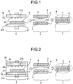
- FIG. 1 is a schematic view illustrating a first embodiment of a method for producing a resin bonded body 9 of the present invention.
- the method according to the first embodiment includes a thermoforming step 5 of thermoforming a bonding surface 3 of a first resin member 1 to be bonded to a second resin member 2 and/or a bonding surface 3' of the second resin member 2 to be bonded to the first resin member 1 with the bonding surface 3 and/or 3' covered with inert gas by a molding unit 21; a surface treatment step 6 of activating the bonding surface 3 of the first resin member 1 and/or the bonding surface 3' of the second resin member 2 by a surface treatment unit 4 after the thermoforming step 5; and a bonding step 7 of attaching the first resin member 1 and the second resin member 2 to each other through the bonding surface of each of the first resin member 1 and the second resin member 2 after the surface treatment step 6.
- polyethylene polyethylene
- PP polypropylene
- PA polyamide
- POM polyacetal
- PET polyethylene terephthalate
- PBT polybutylene terephthalate
- PES polyphenylene sulfide
- PEEK polyetheretherketone
- PTFE polytetrafluoroethylene
- PVC polyvinyl chloride
- PS polystyrene
- ABS acrylonitrile butadiene styrene
- ABS polymethyl methacrylate
- PC polycarbonate
- PEI polyetherimide
- PAI polyamideimide
- a material containing no aromatic moiety in the molecular structure is used. This is because the material containing no aromatic moiety has high thermal mobility of a molecular chain and molecular diffusion (entanglement of the molecular chain) at a bonding interface between the first resin member 1 and the second resin member 2 is increased. As this molecular diffusion is increased, the intermolecular force at the bonding interface is increased, and the bonding force is enhanced.
- the types of the first resin member 1 and the second resin member 2 may be different from each other.
- the types of the first resin member 1 and the second resin member 2 are the same from the viewpoint of entanglement of the molecular chain at the interface between the bonding surface 3 of the first resin member 1 and the bonding surface 3' of the second resin member 2 during bonding.
- thermoforming in the present invention refers to molding a resin under heating.
- the bonding surface 3 of the first resin member 1 and/or the bonding surface 3' of the second resin member 2 is thermoformed by the molding unit 21 for formation of any concavo-convex shape, improvement in smoothness, or the like.
- the molding unit 21 for formation of any concavo-convex shape, improvement in smoothness, or the like.
- only one of the bonding surface 3 and the bonding surface 3' may be thermoformed, or both the bonding surface 3 and the bonding surface 3' may be thermoformed.
- the bonding surface 3 of the first resin member 1 is thermoformed will be described, unless specified otherwise.
- the bonding surface 3' is thermoformed, the first resin member 1 only needs to be replaced with the second resin member 2, and the bonding surface 3 only needs to be replaced with the bonding surface 3'.
- the molding unit 21 at the thermoforming step 5 is not particularly limited, and examples thereof may include heat press molding such as heat imprint working, and laser working.
- inert gas is supplied to the bonding surface 3 of the first resin member 1 to be thermoformed, by a gas supply unit 18 such as a gas nozzle.
- a gas supply unit 18 such as a gas nozzle.
- the bonding surface 3 can efficiently be covered with the inert gas.
- a reaction with an oxidizing substance such as oxygen or carbon dioxide can be suppressed, and thermal degradation of the bonding surface 3 during thermoforming can be reduced.
- “Thermal degradation” in the present invention refers to oxidative deterioration causing a decrease in molecular weight (degradation) at the bonding surface 3, cross-linking, or the like, in cleavage of a molecular chain of a resin caused by oxidation and heat.
- the “inert gas” in the present invention refers to gas that does not cause an oxidation reaction, and examples of types of the inert gas include rare gases such as argon, helium, and neon, and nitrogen gas. Among them, it is preferable that nitrogen gas is used from the viewpoint of cost.
- the inert gas supplied from the gas supply unit 18 may be a single gas, or a plurality of types of inert gases may be mixed.
- An environment filled with the inert gas in the present invention is a state where the oxygen concentration in the air in contact with the bonding surface 3 is less than 20%. As the oxygen concentration is decreased, thermal degradation is reduced, and the bonding force of the resin bonded body 9 is increased.
- the oxygen concentration at the bonding surface 3 to be thermoformed can be measured with a zirconia oxygen analyzer, a magnetic oxygen analyzer, or the like.
- the temperature, pressure, and time during thermoforming can appropriately be set. However, it is preferable that the temperature during thermoforming is set to be equal to or lower than the glass transition temperature (Tg) of a resin constituting the first resin member 1. This is because the whole resin member may be thermally modified at a temperature higher than Tg. It is more preferable that the temperature during thermoforming is set to be equal to or lower than the temperature of deflection under load at which the first resin member 1 can be molded.
- the temperature of deflection under load depends on Tg of the first resin member 1 and the pressure during thermoforming. The temperature of deflection under load can be decreased with an increase in pressure. Therefore, when the pressure during thermoforming is increased, the bonding surface 3 of the first resin member 1 can be thermoformed at a temperature lower than Tg, and a risk of thermal modification is suppressed.
- the temperature of deflection under load can be calculated from a change in elastic modulus relative to the temperature of a sample defined by JIS K7191 (2007).
- the temperature, pressure, and time during thermoforming of the first resin member 1 may be the same as or different from the temperature, pressure, and time during thermoforming of the second resin member 2.
- the bonding surface 3 that is a thermoformed surface of the first resin member 1 can be made smooth, or a concavo-convex shape can be formed on the bonding surface 3.
- a concavo-convex shape can be formed on the bonding surface 3.
- the surface treatment step 6 will be described.
- the bonding surface 3 of the first resin member 1 and/or the bonding surface 3' of the second resin member 2 is surface-treated by the surface treatment unit 4, to activate the bonding surface 3 and/or 3'. Only one of the bonding surface 3 and the bonding surface 3' or both the bonding surface 3 and the bonding surface 3' may be surface-treated.
- the bonding surface 3 and/or 3' that is thermoformed at the thermoforming step 5 or the bonding surface 3 and/or 3' that is not thermoformed may be surface-treated.
- the bonding surface 3 of the first resin member 1 is surface-treated will be described, unless specified otherwise.
- the bonding surface 3' is surface-treated, the first resin member 1 only needs to be replaced with the second resin member 2, and the bonding surface 3 only needs to be replaced with the bonding surface 3'.
- Activating in the present invention means cleaving a molecular chain in a surface layer of the bonding surface 3 by applying energy to the bonding surface 3 of the first resin member 1 and/or imparting a functional group.
- the thermal mobility of the molecular chain that is present at the bonding surface 3 can be increased (softening temperature can be lowered).
- a polar functional group such as a hydroxyl group can be produced.
- the thermal mobility of the molecular chain can be measured with a nano-thermal microscope (Nano TA) or the like.
- the type and production amount of the polar functional group can be confirmed by infrared absorption spectroscopy (IR) or the like.
- the surface treatment unit 4 at the surface treatment step 6 only needs to be a method in which the bonding surface 3 of the first resin member 1 can be activated by applying energy to the bonding surface 3 of the first resin member 1 as described above, and any method can be used.
- any one of the bonding surface 3 and the bonding surface 3' or both the bonding surface 3 and the bonding surface 3' may be surface-treated. However, when any one of the bonding surface 3 and the bonding surface 3', for example, only the bonding surface 3 is thermoformed, it is preferable that only the bonding surface 3' that is not thermoformed is surface-treated to prevent as much as possible a concavo-convex shape formed during thermoforming from thermally deforming.
- Examples of the surface treatment unit 4 for surface treatment include a unit for irradiating the bonding surface 3 of the first resin member 1 with an ionizing substance and a unit for irradiating the bonding surface 3 of the first resin member 1 with an electromagnetic wave.
- the units any one may be used, or a plurality of the units may be used.
- the surface treatment unit 4 it is possible to cleave a molecular chain at a low temperature as compared with a flame treatment such as ITRO treatment. Therefore, even when a concavo-convex shape is formed on the bonding surface 3 during thermoforming, the surface treatment can be performed without thermally deforming the concavo-convex shape.
- the strength, time, frequency, and the like of the surface treatment are changed, the amount of a cleaved molecular chain and the amount of an imparted functional group at the bonding surface 3 of the first resin member 1 can easily be controlled.
- the "ionizing substance" in the present invention is gas containing a charged particle such as an ion and an electron.
- a method for generating the ionizing substance include, but not particularly limited to, a method for applying a voltage (electric field) between metal electrode plates that are spaced apart and that are faced to each other.
- Examples of the type of gas that produces the ionizing substance include, but not particularly limited to, argon, helium, oxygen, water vapor, and nitrogen.
- the “electromagnetic wave” in the present invention is a wave formed by a change in electric field and magnetic field of a space. As the wavelength of this wave is decreased, the energy is increased. In particular, when the bonding surface 3 of the first resin member 1 is irradiated with an electromagnetic wave having a wavelength of 200 nm or less, the bonding surface 3 can effectively be activated. When the amount (illuminance), wavelength, and the like of the electromagnetic wave are changed, the type and amount of the functional group produced at the bonding surface 3 of the first resin member 1 can easily be controlled.
- the bonding step 7 will be described.
- the bonding surface 3 of the first resin member 1 and the bonding surface 3' of the second resin member 2 are faced to each other and attached to each other after the thermoforming step 5 and the surface treatment step 6.
- molecular diffusion entanglement of a molecular chain at the interface between the bonding surface 3 of the first resin member 1 and the bonding surface 3' of the second resin member 2
- formation of a covalent bond proceeds. Therefore, the bonding force of the resin bonded body 9 can be enhanced, and the resin bonded body 9 having a strong bonding force can be produced.
- the molecular diffusion and the formation of a covalent bond can be promoted further by reducing thermal degradation of the bonding surface 3 of the first resin member 1 and the bonding surface 3' of the second resin member 2 at the thermoforming step 5 and increasingly activating the bonding surface 3 and/or the bonding surface 3' at the surface treatment step 6.
- first resin member 1 and the second resin member 2 are pressure-bonded by a press or the like so that a space due to waviness of the bonding surface 3 of the first resin member 1 and the bonding surface 3' of the second resin member 2, or the like is not generated at the bonding interface. In this case, the actual contact area between the first resin member 1 and the second resin member 2 is increased, and the bonding force of the resin bonded body 9 is enhanced.
- the temperatures of the first resin member 1 and the second resin member 2 are higher at the bonding step 7, the molecular diffusion and the condensation reaction at the bonding interface of the resin bonded body 9 are promoted.
- the temperatures of the first resin member 1 and the second resin member 2 are a temperature higher than Tg of resins constituting the respective resin members, the molecular structures of the resins constituting the respective resin members are changed (thermally modified), and the machine characteristics, optical characteristics, and the like of the first resin member 1 and the second resin member 2 may be deteriorated. Therefore, it is preferable that the temperatures of the whole first resin member 1 and the whole second resin member 2 at the bonding step 7 are set to be equal to or lower than Tg.
- a good resin bonded body 9 can be produced without changing the molecular structures of the resins constituting the first resin member 1 and the second resin member 2, and the like.
- the temperatures of the first resin member 1 and the second resin member 2 at the bonding step 7 may be the same as or different from each other.
- a unit for heating the first resin member 1 and the second resin member 2 at the bonding step 7 is not particularly limited, and an infrared radiation heater, a microwave heater, an ultrasonic heater, a heat press machine, a hot air drier, a heating furnace, or the like can be used.
- the resin bonded body 9 may be post-heated.
- a post-heating unit is not particularly limited, and an infrared radiation heater, a microwave heater, an ultrasonic heater, a heat press machine, a hot air drier, a heating furnace, or the like can be used. It is preferable that the temperature of post-heating is set to be equal to or lower than the glass transition temperatures (Tg) of the first resin member 1 and the second resin member 2 from the viewpoint of preventing thermal modification.
- Tg glass transition temperatures
- FIG. 2 is a schematic view illustrating a second embodiment of the method for producing the resin bonded body 9 of the present invention.
- the thermoforming step is a difference between the method according to the first embodiment and the method according to the second embodiment.
- inert gas is supplied to the bonding surface 3 of the first resin member 1 to be thermoformed.
- a partition 20 is provided so as to surround the bonding surface 3 of the first resin member 1 as illustrated in FIG. 2 , and inert gas is supplied to the inside of the partition 20 from the gas supply unit 18.
- the inert gas is supplied to the inside of the partition 20 as described above, the inside of the partition 20 can be filled with the inert gas. Therefore, a state where the bonding surface 3 of the first resin member 1 is covered with the inert gas can be produced like the method according to the first embodiment.
- the whole first resin member 1 is surrounded by the partition 20.
- the thermoforming step 5 may be performed with the whole second resin member 2 surrounded by the partition 20.
- the thermoforming step 5 may be performed with the whole first resin member 1 and the whole second resin member 2 surrounded by the partition 20, or the thermoforming step 5 may be performed with only the bonding surface 3 of the first resin member 1 or the bonding surface 3' of the second resin member 2 surrounded by the partition 20.
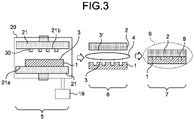
- FIG. 3 is a schematic view illustrating a third embodiment of the method for producing the resin bonded body 9 of the present invention.
- the thermoforming step 5 is a difference between the method according to the first embodiment and the method according to the third embodiment.
- inert gas is supplied to the bonding surface 3 of the first resin member 1 to be thermoformed.
- the partition 20 is provided so as to surround the bonding surface 3 of the first resin member 1 as illustrated in FIG. 3 , air inside the partition 20 is exhausted by an exhausting unit 19, and the inside of the partition 20 is made in a vacuum state.
- the whole first resin member 1 is surrounded by the partition 20.
- the thermoforming step 5 may be performed with the whole second resin member 2 surrounded by the partition 20.
- the thermoforming step 5 may be performed with the whole first resin member 1 and the whole second resin member 2 surrounded by the partition 20, or only the bonding surface 3 of the first resin member 1 or the bonding surface 3' of the second resin member 2 may be surrounded by the partition 20.
- FIG. 4 is a schematic view illustrating a fourth embodiment of the method for producing the resin bonded body 9 of the present invention.
- inert gas is supplied to the bonding surface 3 of the first resin member 1 and the bonding surface is thermoformed with the bonding surface covered with the inert gas at the thermoforming step 5, the bonding surface 3' of the second resin member that is not thermoformed at the thermoforming step 5 is activated at the surface treatment step 6, and the bonding surface 3 of the first resin member 1 is attached to the bonding surface 3' of the second resin member 2 at the bonding step 7 after the thermoforming step 5 and the surface treatment step 6.
- the surface treatment step 6 is performed after the thermoforming step 5.
- the thermoforming step 5 and the surface treatment step 6 may be performed in any order or in parallel, as illustrated in FIG. 4 . This is because the bonding surface 3 to be thermoformed at the thermoforming step 5 is different from the bonding surface 3' to be surface-treated at the surface treatment step 6.
- the bonding surface 3 of the first resin member 1 is thermoformed, and the bonding surface 3' of the second resin member 2 is surface-treated.
- the bonding surface 3' of the second resin member 2 may be thermoformed, and the bonding surface 3 of the first resin member 1 may be surface-treated.
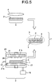
- FIG. 5 is a schematic view illustrating a fifth embodiment of the method for producing the resin bonded body 9 of the present invention.
- the method according to the fifth embodiment is the same as the method according to the fourth embodiment except that the thermoforming step 5 is changed. Specifically, in the method according to the fourth embodiment, inert gas is supplied to the bonding surface 3 of the first resin member 1 to be thermoformed at the thermoforming step 5.
- the bonding surface 3 of the first resin member 1 is surrounded by the partition 20, air inside of the partition 20 is exhausted, and the inside of the partition 20 is made in a vacuum state at the thermoforming step 5, as illustrated in FIG. 5 . That is, the same step as the thermoforming step 5 in the method according to the third embodiment is performed.
- thermoforming step 5 and the surface treatment step 6 may be performed in any order or in parallel, as illustrated in FIG. 5 . This is because the bonding surface 3 to be thermoformed at the thermoforming step 5 is different from the bonding surface 3' to be surface-treated at the surface treatment step 6.
- the bonding surface 3 of the first resin member 1 is thermoformed, and the bonding surface 3' of the second resin member 2 is surface-treated.
- the bonding surface 3' of the second resin member 2 may be thermoformed, and the bonding surface 3 of the first resin member 1 may be surface-treated.
- FIG. 6 is a schematic view illustrating a sixth embodiment of the method for producing the resin bonded body 9 of the present invention.
- an active liquid 12 is used for a surface treatment unit 4A at the surface treatment step 6, and the active liquid 12 is sprayed or applied by a liquid contact system 13.
- the active liquid 12 can be brought into contact with the bonding surface 3 of the first resin member 1 and the bonding surface 3' of the second resin member 2.
- the method according to the sixth embodiment is a method in which the surface treatment unit 4 at the surface treatment step 6 in the method according to the first embodiment is limited to a unit for contacting an active liquid.
- the surface treatment step 6 in the methods according to the second to fifth embodiments can also be changed to the same step as the surface treatment step 6 in the method according to the sixth embodiment.
- the bonding surface 3 of the first resin member 1 and the bonding surface 3' of the second resin member 2 are surface-treated. However, only any one of the bonding surface 3 and the bonding surface 3' may be surface-treated. Alternatively, the bonding surface 3' of the second resin member 2 may be thermoformed, and the bonding surface 3 of the first resin member 1 and/or the bonding surface 3' of the second resin member 2 may be surface-treated.
- the "active liquid 12" in the present invention is a liquid containing one or more types of active species such as atoms and molecules (radicals) having a highly reactive unpaired electron, ions, and electrons (charged particles).
- the degree of activity indicating the degree of activation of the active liquid 12 can be evaluated, for example, by measurement of light-emitting intensity generated from the active species, chemical quantitative determination that measures the reaction amounts of the active species and a test liquid, electron spin resonance analysis, or the like.
- the active liquid 12 is obtained by activating a liquid.
- the type of liquid to be activated include water, methanol, ethanol, acetic acid, and ammonia.
- the type of the liquid can widely be selected according to cost, safety, the dissolution resistance of the resin members 1 and 2, and the like.
- the liquid to be activated may be a mixed solution or an aqueous solution in which two or more types of liquids are mixed.
- the active liquid 12 can be produced by activating the liquid with a liquid activation unit 10.
- the liquid activation unit 10 only needs to be a method for applying energy to the liquid to dissociate or ionize a molecule of the liquid, and can appropriately be selected. It is particularly preferable that the activation unit 10 is a unit for irradiating the liquid with an ionizing substance, irradiating the liquid with an electromagnetic wave, vibrating the liquid with an elastic vibration wave (sound pressure), or applying an electric field to the liquid.
- any one may be used, or a plurality of the units may be used. By the units, many active species can be produced in the liquid for a short time at a high decomposition efficiency of the liquid. All of the activation units 10 are preferable since the controllability for activation of the liquid is high.
- Examples of the method for irradiating the liquid with an ionizing substance include transporting a produced ionizing substance to the liquid using a gas stream, spraying the liquid to an ionizing substance generating part, and introducing charged particles by arranging a metal electrode plate different from a metal electrode plate for generation of an ionizing substance in the liquid and applying a direct electric current.
- the liquid is irradiated with an ionizing substance, the liquid is decomposed and activated.
- Examples of the type of gas for production of an ionizing substance include, but not particularly limited to, argon, helium, oxygen, water vapor, and nitrogen.
- the active liquid 12 that is appropriate can be produced according to the types of the first resin member 1 and the second resin member 2.
- the "electric field” in the present invention refers to a state where a voltage is applied. When this electric field is applied to the liquid, the liquid is electrolyzed and activated.
- a method for generating an electric field is not particularly limited, and for example, two metal plates are inserted into the liquid, and a potential difference is applied to the metal plates to generate an electric field. When the distance between the two metal plates, the applied voltage, and the like are changed, the electric field intensity can easily be changed, and the degree of activity of the liquid can be controlled.
- the reaction rate is also increased with an increase in temperature of the liquid. Therefore, when the liquid temperature is increased, the decomposition of the liquid can be promoted. Further, when energy is applied by the activation unit 10 while the liquid is stirred with a stirrer, the active liquid 12 that is homogeneous can be produced.
- the liquid contact system 13 is not particularly limited, and examples thereof include a system for conveying the active liquid 12 from a container 11 using a pump and then spraying the active liquid 12 from a spray nozzle, and a system for applying the active liquid 12 to the bonding surface 3 of the first resin member 1 and the bonding surface 3' of the second resin member 2 by an applying machine.
- FIG. 7 is a schematic view illustrating a seventh embodiment of the method for producing a resin bonded body of the present invention.
- immersion of the first resin member 1 and the second resin member 2 in the active liquid 12 is performed as a surface treatment unit 4B.
- the bonding surface 3 of the first resin member 1 and/or the bonding surface 3' of the second resin member 2 may be brought into contact with the active liquid 12.
- energy is obtained from the liquid activation unit 10. Therefore, the bonding surface 3 of the first resin member 1 and the bonding surface 3' of the second resin member 2 can efficiently be activated together with a reaction with the active liquid 12.
- the method according to the seventh embodiment is also a method in which the surface treatment unit 4 at the surface treatment step 6 in the method according to the first embodiment is limited to a unit for contacting an active liquid.
- the surface treatment step 6 in the methods according to the second to fifth embodiments can be changed to the same step as the surface treatment step 6 in the method according to the seventh embodiment.
- the bonding surface 3 of the first resin member 1 and the bonding surface 3' of the second resin member 2 are surface-treated. However, only any one of the bonding surface 3 and the bonding surface 3' may be surface-treated. Alternatively, the bonding surface 3' of the second resin member 2 may be thermoformed, and the bonding surface 3 of the first resin member 1 and/or the bonding surface 3' of the second resin member 2 may be surface-treated.
- FIG. 8 is a schematic view illustrating a first embodiment of a device for producing the resin bonded body 9 of the present invention.
- the device for producing the resin bonded body 9 according to the first embodiment includes a thermoforming system 14, a surface treatment system 15, and a bonding system 16.
- the methods according to the first and fourth embodiments can be achieved.
- the thermoforming system 14 includes the gas supply unit 18 for supplying inert gas to the bonding surface 3 of the first resin member 1, and the molding unit 21 for molding the bonding surface 3 while the bonding surface 3 covered with the inert gas is heated.
- the gas supply unit 18 is not particularly limited. It is preferable that a gas nozzle or the like is used and be disposed so that a gas supply port 26 thereof faces the bonding surface 3. Thus, the bonding surface 3 can efficiently be covered with the inert gas. Alternatively, a plurality of the gas supply units 18 may be arranged. It is preferable that the thermoforming system 14 further includes an oxygen meter 24 to confirm whether the bonding surface 3 is covered with the inert gas.
- the molding unit 21 is not particularly limited, and examples thereof include a heat press molding machine such as a heat imprint working machine, and a laser working machine.
- the surface treatment unit 4 of the surface treatment system 15 includes a substrate-holding system 27 and an electrode 32. It is preferable that the electrode 32 is disposed to face the bonding surface 3 of the first resin member 1 disposed on the substrate-holding system 27. Thus, it is possible to uniformly surface-treat the bonding surface 3.
- the surface treatment unit 4 is an ionizing substance-emitting device for emitting an ionizing substance 22.
- a gas supply unit 31 for supplying a gas type for producing the ionizing substance 22 is provided between the first resin member 1 and the electrode 32.
- the surface treatment unit 4 only needs to be a method for applying energy to the bonding surface 3 to cleave a molecular chain and/or a method for imparting a functional group.
- the surface treatment unit 4 can appropriately be changed.
- an electromagnetic wave-emitting device for emitting an electromagnetic wave can also be used.
- the electromagnetic wave-emitting device it is preferable that the gas supply unit 31 is provided similarly to the electrolytically dissociating substance-emitting device.
- an active liquid contact system for example, the surface treatment unit 4A illustrated in FIG. 6 or the surface treatment unit 4B illustrated in FIG. 7 may be used.
- the surface treatment unit 4A of FIG. 6 is a unit in which the liquid 12 in the container 11 is activated by the liquid activation unit 10, and the active liquid 12 is sprayed or applied by the liquid contact system 13.
- the surface treatment unit 4B illustrated in FIG. 7 is a unit in which the first resin member 1 and the second resin member 2 are immersed in the active liquid 12 in the container 11.
- the surface treatment system 15 may include a plurality of types of surface treatment units.
- a process-monitoring unit 28 for monitoring a process is provided in the surface treatment system 15.
- the process-monitoring unit 28 is provided, an abnormality during a surface treatment can early be found.
- the process-monitoring unit 28 is appropriately changed according to a subject to be monitored.
- the ionizing substance-emitting device includes an emission spectrophotometer capable of measuring the light emission state of the ionizing substance.
- the type and degree of electrolytic dissociation of the ionizing substance can be acquired.
- the electromagnetic wave-emitting device includes an illuminometer, a luminance meter, or the like.
- the active liquid contact system includes a pH meter, a dissolved oxygen meter, or the like.
- the active state of the active liquid 12 can be acquired.
- the gas type, the humidity, and the temperature in the surface treatment system 15 can be monitored with a mass spectrometer, a hygrometer, a thermometer, or the like.
- the bonding system 16 is a unit for attaching the bonding surface 3 of the first resin member 1 and the bonding surface 3' of the second resin member 2 to each other, and examples thereof include a thermocompression-bonding unit such as a heat press machine. A plurality of the thermocompression-bonding units may be arranged.
- a post-heating unit for post-heating the resin bonded body 9 is disposed after the bonding system 16.
- the molecular diffusion and the formation of a covalent bond at the bonding interface are promoted, and the bonding force of the resin bonded body 9 can be further enhanced.
- the bonding surface 3 of the first resin member 1 is thermoformed by the thermoforming system 14, and then surface-treated by the surface treatment system 15.
- the bonding surface 3' of the second resin member 2 may be thermoformed by the thermoforming system 14, and may be surface-treated by the surface treatment system 15.
- FIG. 9 is a schematic view illustrating a second embodiment of the device for producing the resin bonded body 9 of the present invention.
- a thermoforming system 14A is a difference between the device according to the first embodiment and the device according to the second embodiment.
- the thermoforming system 14A in the device according to the second embodiment includes the partition 20 provided so as to surround the first resin member 1, the gas supply unit 18 for supplying inert gas to the inside of the partition 20, and the molding unit 21 that is provided inside the partition 20 and molds the bonding surface 3 of the first resin member 1 under heating.
- the bonding surface 3 can efficiently be covered with the inert gas.
- the whole first resin member 1 is surrounded by the partition 20.
- the whole second resin member 2 may be surrounded by the partition 20.
- the whole first resin member 1 and the whole second resin member 2 may be surrounded by the partition 20, or only the bonding surface 3 of the first resin member 1 or the bonding surface 3' of the second resin member 2 may be surrounded by the partition 20.
- FIG. 10 is a schematic cross-sectional view illustrating a third embodiment of the device for producing a resin bonded body of the present invention.
- a thermoforming system 14B is a difference between the device according to the first embodiment and the device according to the third embodiment.
- the thermoforming system 14B in the device according to the third embodiment includes the partition 20 provided so as to surround the first resin member 1, the exhausting unit 19 for exhausting air in the inside of the partition 20 resulting in a vacuum state, and the molding unit 21 that is provided inside the partition 20 and molds the bonding surface 3 of the first resin member 1 under heating.
- the bonding surface 3 can efficiently be placed in a vacuum environment.
- a vacuum gauge 23 is provided.
- the whole first resin member 1 is surrounded by the partition 20.
- the whole second resin member 2 may be surrounded by the partition 20.
- the whole first resin member 1 and the whole second resin member 2 may be surrounded by the partition 20, or only the bonding surface 3 of the first resin member 1 or the bonding surface 3' of the second resin member 2 may be surrounded by the partition 20.
- FIG. 11 is a schematic view illustrating a fourth embodiment of the device for producing a resin bonded body of the present invention.
- the device according to the fourth embodiment includes a resin member-conveying system 17 for automatically conveying the first resin member 1 and the second resin member 2, in addition to the thermoforming system 14, the surface treatment system 15, and the bonding system 16.
- the resin member-conveying system 17 is not particularly limited, and examples thereof include a belt conveyor that conveys the first resin member 1 and the second resin member 2 with an annular belt rotated on a truck, and a conveying robot that self-travels between the steps and carries the first resin member 1 and the second resin member 2.
- FIG. 12 is a schematic view illustrating a fifth embodiment of the device for producing a resin bonded body of the present invention.
- the device according to the fifth embodiment includes a resin member-conveying system including unwinding rollers 17a and 17a', a Winding roller 17b, and a conveying roller 17c, in addition to the thermoforming system 14, the surface treatment system 15, and the bonding system 16.
- the first resin member 1 is unrolled by the unwinding roller 17a
- the second resin member 2 is unrolled by the unwinding roller 17a'
- the first resin member 1, the second resin member 2, and the resin bonded body 9 are conveyed by the conveying roller 17c
- the resin bonded body 9 is rolled by the winding roller 17b.
- the second resin member 1 and the second resin member 2 are a thin long-length substrate, the resin bonded body 9 can continuously be produced, and productivity can be enhanced. According to the treatment times at the steps, intermittent conveyance may be performed.
- FIG. 13 is a schematic view illustrating a sixth embodiment of the device for producing a resin bonded body of the present invention.
- the thermoforming system 14B is a difference between the aforementioned device according to the fifth embodiment and the device according to the sixth embodiment.
- the thermoforming system 14B in the device according to the sixth embodiment includes the partition 20 provided so as to surround each of the bonding surface 3 of the first resin member 1 and the bonding surface 3' of the second resin member 2, the exhausting unit 19 for exhausting air in the inside of the partition 20 resulting in a vacuum state, and the molding unit 21 that is provided inside the partition 20 and molds the bonding surface 3 of the first resin member 1 and the bonding surface 3' of the second resin member 2 under heating.
- a load-lock system 29 is provided at a substrate conveyance port of the partition 20 in the thermoforming system 14B.
- the load-lock system 29 is a system that blocks entry of air from the outside of the partition 20 to maintain the degree of vacuum in the inside of the partition 20. By the load-lock system 29, vacuum can efficiently be made inside the partition 20.
- FIG. 14 is a schematic view illustrating a seventh embodiment of the device for producing a resin bonded body of the present invention.
- the device for producing a resin bonded body according to the seventh embodiment includes the thermoforming system 14 having the gas supply unit 18 on a conveying route of the first resin member 1, and the surface treatment system 15 on a conveying route of the second resin member 2, and the bonding system 16 is disposed on a conveying route after the thermoforming system 14 and the surface treatment system 15.
- the bonding surface 3 When the bonding surface 3 is thermoformed with the bonding surface 3 covered with inert gas, thermal degradation can be reduced.
- the bonding surface 3' that is different from the bonding surface 3 and is not thermoformed is activated by the surface treatment system 15, the resin bonded body 9 having a high bonding force can be produced.
- the device for producing a resin bonded body may include the thermoforming system 14 having the gas supply unit 18 on the conveying route of the second resin member 2, and the surface treatment system 15 on the conveying route of the first resin member 1.
- FIG. 15 is a cross-sectional view illustrating an eighth embodiment of the device for producing a resin bonded body of the present invention.
- the thermoforming system 14B having the partition 20 and the exhausting unit 19 is disposed on the conveying route of the first resin member 1
- the surface treatment system 15 is disposed on the conveying route of the second resin member 2
- the bonding system 16 is disposed on the conveying route after the thermoforming system 14B and the surface treatment system 15.
- the bonding surface 3 When the bonding surface 3 is thermoformed in vacuum, thermal degradation can be reduced.
- the bonding surface 3' that is different from the bonding surface 3 and is not thermoformed is activated by the surface treatment system 15, the resin bonded body 9 having a strong bonding force can be produced.
- the device for producing a resin bonded body may include the thermoforming system 14B having the partition 20 and the exhausting unit 19 on the conveying route of the second resin member 2, and the surface treatment system 15 on the conveying route of the first resin member 1.
- the resin bonded body 9 was produced.
- a PMMA substrate (TECHNOLLOY (registered trademark) S000, glass transition temperature: 100°C) that had a thickness of 0.2 mm and was a square with a side of 50 mm was used (hereinafter, the first resin member 1 is called PMMA1, and the second resin member 2 is called PMMA2).
- the surface roughness (arithmetic average roughness Ra) of the PMMA substrate was confirmed with a three-dimensional microscope (OLYMPUS OLS3100), to be 10 nm.
- thermoforming step 5 a heat press molding machine was used as the molding unit 21, and nitrogen gas was used as the inert gas.
- the PMMA1 was placed on the unmolded surface 21a that was a square with a side of 100 mm, and nitrogen gas was supplied at 10 L/min to the bonding surface 3 of the PMMA1 by the gas supply unit 18.
- the oxygen concentration at the bonding surface 3 of PMMA1 was measured with an oxygen meter (COSMOS XP-3180), to be 15%.
- the temperatures of the unmolded surface 21a and the molding surface 21b of the heat press molding machine 21 were increased until the temperature of the bonding surface 3 was 130°C, and the bonding surface 3 was then thermoformed at a molding pressure of 6 MPa for 2 minutes.
- the protrusion pattern 30 including rectangular protrusions at an interval of 50 ⁇ m (distances b and e) on a press surface that was a square with a side of 100 mm as illustrated in FIG. 16 was provided.
- a protrusion width a, a protrusion length b, and a protrusion height c were 50 ⁇ m.
- the bonding surface 3 of PMMA1 was subjected to heat imprint molding so that the protrusion pattern 30 of the molding surface 21b was transferred.
- the electrode 32 was disposed to face the bonding surface 3 of PMMA1 held by the substrate-holding system 27 (SUS304) at a position separated from the bonding surface 3 by 2 mm, and the bonding surface 3 of PMMA1 was surface-treated for 10 seconds.
- Nitrogen gas was supplied to a space between the substrate-holding system 27 (SUS304) that was at a grounding potential and was a square with a side of 100 mm, and the electrode 32 under an atmospheric pressure at 40 L/min from a gas nozzle that was the gas supply unit 18, and then a voltage (10 kV) was applied to the substrate-holding system 27 and the electrode 32 by a DC pulse power supply not shown, to produce an ionizing gas.
- SUS304 substrate-holding system 27
- the electrode 32 under an atmospheric pressure at 40 L/min from a gas nozzle that was the gas supply unit 18, and then a voltage (10 kV) was applied to the substrate-holding system 27 and the electrode 32 by a DC pulse power supply not shown, to produce an ionizing gas.
- PMMA2 was subjected to the thermoforming step 5 and the surface treatment step 6 under the same conditions as described above.
- a heat press machine was used as the bonding system 16.
- the press surface temperature of the heat press machine 16 was increased to adjust each substrate temperature of PMMA1 and PMMA2 to 95°C.
- the substrate temperatures were confirmed by an infrared thermometer (SATOTECH DT-8855).
- PMMA1 and PMMA2 were thermocompression-bonded by the heat press machine 16 for 10 minutes at 2 MPa so that the apex surface of each protrusion of the protrusion pattern 30 of the bonding surface 3 was in contact with the apex surface of each protrusion of the protrusion pattern 30 of the bonding surface 3'.
- PMMA1 was bonded to PMMA2.
- the bonding force of a bonded sample produced as described above was evaluated by a 90° peeling test machine (SHIMADZU CORPORATION, AGS-100A). At that time, the peeling rate was set to 5 cm/min. As a result, the bonding force of the bonding sample was 0.7 N/cm.
- a bonded sample of PMMA1 and PMMA2 was produced under the same conditions as in Example 1 except that the amount of nitrogen gas supplied by the gas supply unit 18 was changed to 50 L/min.
- the oxygen concentration at the bonding surface 3 of PMMA1 and PMMA2 was 5%.
- the bonding force of the bonded sample produced as described above was 1.3 N/cm.
- the device for producing a resin bonded body according to the second embodiment illustrated in FIG. 9 was used.
- a bonded sample of PMMA1 and PMMA2 was produced under the same conditions as in Example 1 except that at the thermoforming step 5, nitrogen gas was supplied to the inside of the partition 20 that was provided so as to surround a press surface of a square with a side of 100 mm and had an upper surface and a bottom surface having an inside size of a square with a side of 200 mm and a side surface with a height of 300 mm, from the gas supply system 18 at 10 L/min.
- the bonding force of the bonded sample produced as described above was 1.3 N/cm.
- the device for producing a resin bonded body according to the third embodiment illustrated in FIG. 10 was used.
- air was exhausted under vacuum by the exhausting unit 19 so that the gas pressure in the inside of the partition 20 was 50 Pa without supplying inert gas to the inside of the partition 20 that was provided so as to surround a press surface of a square with a side of 100 mm and had an upper surface and a bottom surface having an inside size of a square with a side of 200 mm and a side surface with a height of 300 mm.
- a bonded sample of PMMA1 and PMMA2 was produced.
- the gas pressure was measured with a vacuum gauge (ULVAC G-TRAN) installed in the partition 20.
- the bonding force of the bonded sample produced as described above was 1.3 N/cm.
- a bonded sample of PMMA1 and PMMA2 was produced under the same conditions as in Example 2 except that PMMA1 was thermoformed by a heat press machine as the molding unit 21, but was not surface-treated by the surface treatment system 15, and PMMA2 was not thermoformed by the molding unit 21, but was surface-treated by the surface treatment system 15.
- the bonding force of the bonded sample produced as described above was 1.3 N/cm.
- a bonded sample of PMMA1 and PMMA2 was produced under the same conditions as in Example 4 except that PMMA1 was thermoformed by a heat press machine as the molding unit 21, but was not surface-treated by the surface treatment system 15, and PMMA2 was not thermoformed by an ionizing gas-emitting device as the surface treatment system 21, but was surface-treated by an ionizing gas-emitting device as the surface treatment system 15.
- the bonding force of the bonded sample produced as described above was 1.3 N/cm.
- a bonded sample of PMMA1 and PMMA2 was produced under the same conditions as in Example 1 except that inert gas was not supplied at the thermoforming step 5.
- the bonding force of the bonded sample produced as described above was 0.0 N/cm.
- a bonded sample of PMMA1 and PMMA2 was produced under the same conditions as in Example 5 except that inert gas was not supplied at the thermoforming step 5.
- the bonding force of the bonded sample produced as described above was 0.0 N/cm.
- a bonded sample of PMMA1 and PMMA2 was produced under the same conditions as in Comparative Example 1 except that the thermoforming step 5 and the surface treatment step 6 were performed, and then the bonding step 7 with spraying ethanol between the bonding surfaces 3 and 3' of the resin members was performed.
- the bonding force of the bonded sample produced as described above was 0.3 N/cm.
- Example 1 The results of Examples 1 to 6 and Comparative Examples 1 to 3 were summarized in Table 1.
- a bonding force of 1.0 N/cm or more was evaluated to be O (very good)
- a bonding force of 0.5 N/cm or more and less than 1.0 N/cm was evaluated to be ⁇ (good)
- a bonding force of 0.1 N/cm or more and less than 0.5 N/cm was evaluated to be ⁇ (slightly poor)
- a bonding force of less than 0.1 N/cm was evaluated to be X (poor).
- an adhesive-free resin bonded body having a high bonding force can easily be obtained while the resin bonded body requires a thermoforming step.
- the method can be applied to a packaging material and an optical film, but a range of the application is not limited to them.
Landscapes
- Engineering & Computer Science (AREA)
- Mechanical Engineering (AREA)
- Physics & Mathematics (AREA)
- Toxicology (AREA)
- Health & Medical Sciences (AREA)
- Electromagnetism (AREA)
- Thermal Sciences (AREA)
- Chemical & Material Sciences (AREA)
- Microelectronics & Electronic Packaging (AREA)
- Combustion & Propulsion (AREA)
- Chemical Kinetics & Catalysis (AREA)
- General Chemical & Material Sciences (AREA)
- Plasma & Fusion (AREA)
- Fluid Mechanics (AREA)
- Lining Or Joining Of Plastics Or The Like (AREA)
Abstract
Description
- The present invention relates to a method for producing a resin bonded body including a thermoforming step and a device for producing a resin bonded body. Background
- A technique for bonding various substrates without an adhesive (hereinafter referred to as adhesive-free bonding) for further miniaturization of semiconductor devices, improvement in optical characteristics of optical devices, and the like has been investigated. In particular, in adhesive-free bonding of resins to be bonded, a lamination technique in which resin bonding surfaces are brought into contact with each other and then heated to the melting temperatures of the resins, resulting in welding, is widely used. However, this technique has a problem in that the degree of crystallization, the molecular structure, and the like of a whole resin member are changed (thermally modified) during heating, to adversely affect optical characteristics and mechanical strength.
- Therefore, as a method for bonding a resin to obtain a strong bonding force without imparting heat damage, a method in which bonding surfaces to be bonded of two resin members are surface-treated with an ionizing substance, an electromagnetic wave, or the like, then attached to each other, and pressurized at a low temperature has been investigated. In this adhesive-free bonding, any concavo-convex shape is formed on the resin bonding surface in advance before bonding, and thus, a hollow structure can be formed inside a resin bonded body with the concavo-convex shape maintained. Therefore, the adhesive-free bonding is applicable to microfluidic devices, optical devices, and the like.
-
Patent Literature 1 discloses a method in which a concave is formed on at least one of a bonding surface of a first resin member and a bonding surface of a second resin member for a flow channel-forming member of a biosensor, a fuel cell, or the like, and the resin bonding surfaces are surface-treated with an ionizing substance, an electromagnetic wave, or the like, and then pressurized at lower than 50°C with a solvent interposed between the bonding surfaces of the resin members. - On the other hand, for three-dimensional formation of a resin member, formation of a fine shape on a surface of the resin member, enhancement in surface smoothness, or the like, various molding procedures such as thermal press working and cutting working are applied. In particular, a thermoforming technique in which a resin that is softened under heating is pressed into a die and molded is widely used since any shape can easily be achieved with precision by using a die according to a purpose.
-
Non Patent Literature 1 discloses that a surface of a resin member is heated and then pressurized to transfer a fine structure of a die surface to a resin surface by a heat imprint method that is one of the thermoforming techniques. - Patent Literature 1:
Japanese Patent Application Laid-open No. 2007-245654 - Non Patent Literature 1: Journal of the Japan Society for Precision Engineering, Vol. 76, No. 2, pp. 156 - 160, 2010
- However, the resin member thermoformed by the method described in
Non Patent Literature 1 has a problem in that the surface of the resin member is thermally degraded during thermoforming, and the resin member bonded by the method disclosed inPatent Literature 1 does not have a sufficient bonding force-improving effect. - The present invention has been made in view of the above problems, and provides a method and a device for producing an adhesive-free resin bonded body having a high bonding force to a thermoforming resin member. Further, the present invention provides a method and a device for producing a resin bonded body having good optical characteristics when a resin to be bonded is a transparent body.
- A method for producing a resin bonded body according to the present invention to solve the above problems is a method for producing a resin bonded body including a first resin member and a second resin member that are bonded to each other. The method includes: a thermoforming step of thermoforming a bonding surface of the first resin member to be bonded to the second resin member and/or a bonding surface of the second resin member to be bonded to the first resin member with the bonding surface covered with inert gas or placed in a vacuum environment; a surface treatment step of activating the bonding surface of the first resin member and/or the bonding surface of the second resin member; and a bonding step of attaching the first resin member and the second resin member to each other through the bonding surface of each of the first resin member and the second resin member after the thermoforming step and the surface treatment step.
- A device for producing a resin bonded body according to the present invention to solve the above problems is a device for producing a resin bonded body including a first resin member and a second resin member that are bonded to each other, used in production of the resin bonded body, the device including: a thermoforming system; a surface treatment system; and a bonding system. The thermoforming system includes a gas supply unit configured to supply inert gas to a bonding surface of the first resin member to be bonded to the second resin member and/or a bonding surface of the second resin member to be bonded to the first resin member such that the bonding surface of the first resin member and/or the bonding surface of the second resin member is covered with the inert gas, and a molding unit configured to mold the bonding surface of the first resin member and/or the second resin member that is covered with the inert gas under heating, the surface treatment system is configured to activate the bonding surface of the first resin member and/or the bonding surface of the second resin member, and the bonding system is configured to attach the first resin member and the second resin member to each other through the bonding surface of each of the first resin member and the second resin member.
- Another device for producing a resin bonded body according to the present invention to solve the above problems is a device for producing a resin bonded body including a first resin member and a second resin member that are bonded to each other, used in production of the resin bonded body, the device including: a thermoforming system; a surface treatment system; and a bonding system. The thermoforming system includes a partition provided so as to surround a bonding surface of the first resin member to be bonded to the second resin member and/or a bonding surface of the second resin member to be bonded to the first resin member, a gas supply unit configured to supply inert gas into the partition or an exhausting unit configured to exhaust air in inside of the partition resulting in a vacuum state, and a molding unit that is provided inside the partition, the molding unit being configured to mold the bonding surface of the first resin member and/or the second resin member under heating, the surface treatment system is configured to active the bonding surface of the first resin member and/or the second resin member, and the bonding system is configured to attach the first resin member and the second resin member to each other through the bonding surface of each of the first resin member and the second resin member. Advantageous Effects of Invention
- The present invention provides a method and a device for producing an adhesive-free resin bonded body having a high bonding force even when a resin member is thermoformed. Further, the present invention provides a method and a device for producing an adhesive-free resin bonded body having good optical characteristics when a resin to be bonded is a transparent body.
-
-
FIG. 1 is a schematic view illustrating a first embodiment of a method for producing a resin bonded body of the present invention. -
FIG. 2 is a schematic view illustrating a second embodiment of the method for producing a resin bonded body of the present invention. -
FIG. 3 is a schematic view illustrating a third embodiment of the method for producing a resin bonded body of the present invention. -
FIG. 4 is a schematic view illustrating a fourth embodiment of the method for producing a resin bonded body of the present invention. -
FIG. 5 is a schematic view illustrating a fifth embodiment of the method for producing a resin bonded body of the present invention. -
FIG. 6 is a schematic view illustrating a sixth embodiment of the method for producing a resin bonded body of the present invention. -
FIG. 7 is a schematic view illustrating a seventh embodiment of the method for producing a resin bonded body of the present invention. -
FIG. 8 is a schematic view illustrating a first embodiment of a device for producing a resin bonded body of the present invention. -
FIG. 9 is a schematic view illustrating a second embodiment of the device for producing a resin bonded body of the present invention. -
FIG. 10 is a schematic view illustrating a third embodiment of the device for producing a resin bonded body of the present invention. -
FIG. 11 is a schematic view illustrating a fourth embodiment of the device for producing a resin bonded body of the present invention. -
FIG. 12 is a schematic view illustrating a fifth embodiment of the device for producing a resin bonded body of the present invention. -
FIG. 13 is a schematic view illustrating a sixth embodiment of the device for producing a resin bonded body of the present invention. -
FIG. 14 is a schematic view illustrating a seventh embodiment of the device for producing a resin bonded body of the present invention. -
FIG. 15 is a schematic view illustrating an eighth embodiment of the device for producing a resin bonded body of the present invention. -
FIG. 16 is a schematic view illustrating a molding surface that is formed by a heat press machine used in Examples 1 to 6. - Hereinafter, examples of embodiments of the present invention will be described with reference to the drawings.
FIG. 1 is a schematic view illustrating a first embodiment of a method for producing a resin bondedbody 9 of the present invention. As illustrated inFIG. 1 , the method according to the first embodiment includes athermoforming step 5 of thermoforming abonding surface 3 of afirst resin member 1 to be bonded to asecond resin member 2 and/or abonding surface 3' of thesecond resin member 2 to be bonded to thefirst resin member 1 with thebonding surface 3 and/or 3' covered with inert gas by amolding unit 21; asurface treatment step 6 of activating thebonding surface 3 of thefirst resin member 1 and/or thebonding surface 3' of thesecond resin member 2 by asurface treatment unit 4 after thethermoforming step 5; and abonding step 7 of attaching thefirst resin member 1 and thesecond resin member 2 to each other through the bonding surface of each of thefirst resin member 1 and thesecond resin member 2 after thesurface treatment step 6. - As types of the
first resin member 1 and thesecond resin member 2 used in the present invention, polyethylene (PE), polypropylene (PP), polyamide (PA), polyacetal (POM), polyethylene terephthalate (PET), polybutylene terephthalate (PBT), polyphenylene sulfide (PPS), polyetheretherketone (PEEK), polytetrafluoroethylene (PTFE), polyvinyl chloride (PVC), polystyrene (PS), acrylonitrile butadiene styrene (ABS), polymethyl methacrylate (PMMA), polycarbonate (PC), polyetherimide (PEI), polyamideimide (PAI), or the like can appropriately be selected according to applications. However, it is preferable that a material containing no aromatic moiety in the molecular structure is used. This is because the material containing no aromatic moiety has high thermal mobility of a molecular chain and molecular diffusion (entanglement of the molecular chain) at a bonding interface between thefirst resin member 1 and thesecond resin member 2 is increased. As this molecular diffusion is increased, the intermolecular force at the bonding interface is increased, and the bonding force is enhanced. The types of thefirst resin member 1 and thesecond resin member 2 may be different from each other. However, it is preferable that the types of thefirst resin member 1 and thesecond resin member 2 are the same from the viewpoint of entanglement of the molecular chain at the interface between thebonding surface 3 of thefirst resin member 1 and thebonding surface 3' of thesecond resin member 2 during bonding. - The
thermoforming step 5 will be described. "Thermoforming" in the present invention refers to molding a resin under heating. At thethermoforming step 5, thebonding surface 3 of thefirst resin member 1 and/or thebonding surface 3' of thesecond resin member 2 is thermoformed by themolding unit 21 for formation of any concavo-convex shape, improvement in smoothness, or the like. According to a shape of the resin bondedbody 9 to be obtained, only one of thebonding surface 3 and thebonding surface 3' may be thermoformed, or both thebonding surface 3 and thebonding surface 3' may be thermoformed. In the following description of the thermoforming step, a case where thebonding surface 3 of thefirst resin member 1 is thermoformed will be described, unless specified otherwise. In a case where thebonding surface 3' is thermoformed, thefirst resin member 1 only needs to be replaced with thesecond resin member 2, and thebonding surface 3 only needs to be replaced with thebonding surface 3'. - The
molding unit 21 at thethermoforming step 5 is not particularly limited, and examples thereof may include heat press molding such as heat imprint working, and laser working. - At the
thermoforming step 5, inert gas is supplied to thebonding surface 3 of thefirst resin member 1 to be thermoformed, by agas supply unit 18 such as a gas nozzle. Thus, thebonding surface 3 can efficiently be covered with the inert gas. When thebonding surface 3 is covered with the inert gas, a reaction with an oxidizing substance such as oxygen or carbon dioxide can be suppressed, and thermal degradation of thebonding surface 3 during thermoforming can be reduced. "Thermal degradation" in the present invention refers to oxidative deterioration causing a decrease in molecular weight (degradation) at thebonding surface 3, cross-linking, or the like, in cleavage of a molecular chain of a resin caused by oxidation and heat. Due to this thermal degradation, the thermal mobility of the molecular chain that is present at thebonding surface 3 of thefirst resin member 1 and machine durability are reduced. A change in the molecular structure at thebonding surface 3 due to the thermal degradation can be confirmed by infrared absorption spectroscopy (IR) or the like. - The "inert gas" in the present invention refers to gas that does not cause an oxidation reaction, and examples of types of the inert gas include rare gases such as argon, helium, and neon, and nitrogen gas. Among them, it is preferable that nitrogen gas is used from the viewpoint of cost. The inert gas supplied from the
gas supply unit 18 may be a single gas, or a plurality of types of inert gases may be mixed. - An environment filled with the inert gas in the present invention is a state where the oxygen concentration in the air in contact with the
bonding surface 3 is less than 20%. As the oxygen concentration is decreased, thermal degradation is reduced, and the bonding force of the resin bondedbody 9 is increased. The oxygen concentration at thebonding surface 3 to be thermoformed can be measured with a zirconia oxygen analyzer, a magnetic oxygen analyzer, or the like. - The temperature, pressure, and time during thermoforming can appropriately be set. However, it is preferable that the temperature during thermoforming is set to be equal to or lower than the glass transition temperature (Tg) of a resin constituting the
first resin member 1. This is because the whole resin member may be thermally modified at a temperature higher than Tg. It is more preferable that the temperature during thermoforming is set to be equal to or lower than the temperature of deflection under load at which thefirst resin member 1 can be molded. The temperature of deflection under load depends on Tg of thefirst resin member 1 and the pressure during thermoforming. The temperature of deflection under load can be decreased with an increase in pressure. Therefore, when the pressure during thermoforming is increased, thebonding surface 3 of thefirst resin member 1 can be thermoformed at a temperature lower than Tg, and a risk of thermal modification is suppressed. - The temperature of deflection under load can be calculated from a change in elastic modulus relative to the temperature of a sample defined by JIS K7191 (2007).
- When in addition to the
first resin member 1, thesecond resin member 2 is thermoformed, the temperature, pressure, and time during thermoforming of thefirst resin member 1 may be the same as or different from the temperature, pressure, and time during thermoforming of thesecond resin member 2. - At the
thermoforming step 5, thebonding surface 3 that is a thermoformed surface of thefirst resin member 1 can be made smooth, or a concavo-convex shape can be formed on thebonding surface 3. For example, when thebonding surface 3 of thefirst resin member 1 placed on anunmolded surface 21a is pressed against amolding surface 21b having aprotrusion pattern 30, a rectangular structure having concavo-convex height and width of 100 nm or more, or the like, can be formed on themolding surface 21b. Thus, a finehollow structure 8 can be formed inside the resin bondedbody 9. - The
surface treatment step 6 will be described. At thesurface treatment step 6, thebonding surface 3 of thefirst resin member 1 and/or thebonding surface 3' of thesecond resin member 2 is surface-treated by thesurface treatment unit 4, to activate thebonding surface 3 and/or 3'. Only one of thebonding surface 3 and thebonding surface 3' or both thebonding surface 3 and thebonding surface 3' may be surface-treated. Thebonding surface 3 and/or 3' that is thermoformed at thethermoforming step 5 or thebonding surface 3 and/or 3' that is not thermoformed may be surface-treated. In the following description of the surface treatment step, a case where thebonding surface 3 of thefirst resin member 1 is surface-treated will be described, unless specified otherwise. In a case where thebonding surface 3' is surface-treated, thefirst resin member 1 only needs to be replaced with thesecond resin member 2, and thebonding surface 3 only needs to be replaced with thebonding surface 3'. - "Activating" in the present invention means cleaving a molecular chain in a surface layer of the
bonding surface 3 by applying energy to thebonding surface 3 of thefirst resin member 1 and/or imparting a functional group. By cleaving the molecular chain in the surface layer of thebonding surface 3, the thermal mobility of the molecular chain that is present at thebonding surface 3 can be increased (softening temperature can be lowered). By imparting a functional group, a polar functional group such as a hydroxyl group can be produced. The thermal mobility of the molecular chain can be measured with a nano-thermal microscope (Nano TA) or the like. The type and production amount of the polar functional group can be confirmed by infrared absorption spectroscopy (IR) or the like. - The
surface treatment unit 4 at thesurface treatment step 6 only needs to be a method in which thebonding surface 3 of thefirst resin member 1 can be activated by applying energy to thebonding surface 3 of thefirst resin member 1 as described above, and any method can be used. - Only any one of the
bonding surface 3 and thebonding surface 3' or both thebonding surface 3 and thebonding surface 3' may be surface-treated. However, when any one of thebonding surface 3 and thebonding surface 3', for example, only thebonding surface 3 is thermoformed, it is preferable that only thebonding surface 3' that is not thermoformed is surface-treated to prevent as much as possible a concavo-convex shape formed during thermoforming from thermally deforming. - Examples of the
surface treatment unit 4 for surface treatment include a unit for irradiating thebonding surface 3 of thefirst resin member 1 with an ionizing substance and a unit for irradiating thebonding surface 3 of thefirst resin member 1 with an electromagnetic wave. Among the units, any one may be used, or a plurality of the units may be used. For thesurface treatment unit 4, it is possible to cleave a molecular chain at a low temperature as compared with a flame treatment such as ITRO treatment. Therefore, even when a concavo-convex shape is formed on thebonding surface 3 during thermoforming, the surface treatment can be performed without thermally deforming the concavo-convex shape. When the strength, time, frequency, and the like of the surface treatment are changed, the amount of a cleaved molecular chain and the amount of an imparted functional group at thebonding surface 3 of thefirst resin member 1 can easily be controlled. - The "ionizing substance" in the present invention is gas containing a charged particle such as an ion and an electron. Examples of a method for generating the ionizing substance include, but not particularly limited to, a method for applying a voltage (electric field) between metal electrode plates that are spaced apart and that are faced to each other. Examples of the type of gas that produces the ionizing substance include, but not particularly limited to, argon, helium, oxygen, water vapor, and nitrogen. When the gas type, the density of the ionizing substance, and the like are changed, the amount of a cleaved molecular chain and the amount of an imparted functional group at the
bonding surface 3 of thefirst resin member 1 can easily be controlled. - The "electromagnetic wave" in the present invention is a wave formed by a change in electric field and magnetic field of a space. As the wavelength of this wave is decreased, the energy is increased. In particular, when the
bonding surface 3 of thefirst resin member 1 is irradiated with an electromagnetic wave having a wavelength of 200 nm or less, thebonding surface 3 can effectively be activated. When the amount (illuminance), wavelength, and the like of the electromagnetic wave are changed, the type and amount of the functional group produced at thebonding surface 3 of thefirst resin member 1 can easily be controlled. - The
bonding step 7 will be described. At thebonding step 7, thebonding surface 3 of thefirst resin member 1 and thebonding surface 3' of thesecond resin member 2 are faced to each other and attached to each other after thethermoforming step 5 and thesurface treatment step 6. By attaching the surfaces, entanglement of a molecular chain at the interface between thebonding surface 3 of thefirst resin member 1 and thebonding surface 3' of the second resin member 2 (hereinafter referred to as molecular diffusion) and a condensation reaction between polar functional groups (hereinafter referred to as formation of a covalent bond) proceed. Therefore, the bonding force of the resin bondedbody 9 can be enhanced, and the resin bondedbody 9 having a strong bonding force can be produced. The molecular diffusion and the formation of a covalent bond can be promoted further by reducing thermal degradation of thebonding surface 3 of thefirst resin member 1 and thebonding surface 3' of thesecond resin member 2 at thethermoforming step 5 and increasingly activating thebonding surface 3 and/or thebonding surface 3' at thesurface treatment step 6. - It is preferable that the
first resin member 1 and thesecond resin member 2 are pressure-bonded by a press or the like so that a space due to waviness of thebonding surface 3 of thefirst resin member 1 and thebonding surface 3' of thesecond resin member 2, or the like is not generated at the bonding interface. In this case, the actual contact area between thefirst resin member 1 and thesecond resin member 2 is increased, and the bonding force of the resin bondedbody 9 is enhanced. - When the temperatures of the
first resin member 1 and thesecond resin member 2 are higher at thebonding step 7, the molecular diffusion and the condensation reaction at the bonding interface of the resin bondedbody 9 are promoted. On the other hand, when the temperatures of thefirst resin member 1 and thesecond resin member 2 are a temperature higher than Tg of resins constituting the respective resin members, the molecular structures of the resins constituting the respective resin members are changed (thermally modified), and the machine characteristics, optical characteristics, and the like of thefirst resin member 1 and thesecond resin member 2 may be deteriorated. Therefore, it is preferable that the temperatures of the wholefirst resin member 1 and the wholesecond resin member 2 at thebonding step 7 are set to be equal to or lower than Tg. In this case, a good resin bondedbody 9 can be produced without changing the molecular structures of the resins constituting thefirst resin member 1 and thesecond resin member 2, and the like. The temperatures of thefirst resin member 1 and thesecond resin member 2 at thebonding step 7 may be the same as or different from each other. - A unit for heating the
first resin member 1 and thesecond resin member 2 at thebonding step 7 is not particularly limited, and an infrared radiation heater, a microwave heater, an ultrasonic heater, a heat press machine, a hot air drier, a heating furnace, or the like can be used. - After the resin bonded
body 9 is produced at thebonding step 7, the resin bondedbody 9 may be post-heated. Thus, the molecular diffusion at the bonding interface is promoted, and the bonding force of the resin bondedbody 9 is further enhanced. A post-heating unit is not particularly limited, and an infrared radiation heater, a microwave heater, an ultrasonic heater, a heat press machine, a hot air drier, a heating furnace, or the like can be used. It is preferable that the temperature of post-heating is set to be equal to or lower than the glass transition temperatures (Tg) of thefirst resin member 1 and thesecond resin member 2 from the viewpoint of preventing thermal modification. -
FIG. 2 is a schematic view illustrating a second embodiment of the method for producing the resin bondedbody 9 of the present invention. The thermoforming step is a difference between the method according to the first embodiment and the method according to the second embodiment. In the method according to the first embodiment, inert gas is supplied to thebonding surface 3 of thefirst resin member 1 to be thermoformed. In the method according to the second embodiment, apartition 20 is provided so as to surround thebonding surface 3 of thefirst resin member 1 as illustrated inFIG. 2 , and inert gas is supplied to the inside of thepartition 20 from thegas supply unit 18. When the inert gas is supplied to the inside of thepartition 20 as described above, the inside of thepartition 20 can be filled with the inert gas. Therefore, a state where thebonding surface 3 of thefirst resin member 1 is covered with the inert gas can be produced like the method according to the first embodiment. - In
FIG. 2 , the wholefirst resin member 1 is surrounded by thepartition 20. However, thethermoforming step 5 may be performed with the wholesecond resin member 2 surrounded by thepartition 20. Alternatively, thethermoforming step 5 may be performed with the wholefirst resin member 1 and the wholesecond resin member 2 surrounded by thepartition 20, or thethermoforming step 5 may be performed with only thebonding surface 3 of thefirst resin member 1 or thebonding surface 3' of thesecond resin member 2 surrounded by thepartition 20. -
FIG. 3 is a schematic view illustrating a third embodiment of the method for producing the resin bondedbody 9 of the present invention. Thethermoforming step 5 is a difference between the method according to the first embodiment and the method according to the third embodiment. In the method according to the first embodiment, inert gas is supplied to thebonding surface 3 of thefirst resin member 1 to be thermoformed. In the method according to the third embodiment, thepartition 20 is provided so as to surround thebonding surface 3 of thefirst resin member 1 as illustrated inFIG. 3 , air inside thepartition 20 is exhausted by anexhausting unit 19, and the inside of thepartition 20 is made in a vacuum state. - In the method according to the first embodiment, when the
bonding surface 3 of thefirst resin member 1 is covered with inert gas, a reaction of thebonding surface 3 of thefirst resin member 1 with an oxidizing substance such as oxygen or carbon dioxide is suppressed. However, in the method according to the third embodiment, when the inside of thepartition 20 is made in a vacuum state, a reaction of thebonding surface 3 of thefirst resin member 1 with an oxidizing substance such as oxygen or carbon dioxide is suppressed. "Vacuum" in the present invention refers to a gas pressure lower than 1,013 hPa that is an atmospheric pressure. As the gas pressure is decreased, the amount of the oxidizing substance is decreased, and thermal degradation can be reduced. - In
FIG. 3 , the wholefirst resin member 1 is surrounded by thepartition 20. However, thethermoforming step 5 may be performed with the wholesecond resin member 2 surrounded by thepartition 20. Alternatively, thethermoforming step 5 may be performed with the wholefirst resin member 1 and the wholesecond resin member 2 surrounded by thepartition 20, or only thebonding surface 3 of thefirst resin member 1 or thebonding surface 3' of thesecond resin member 2 may be surrounded by thepartition 20. -
FIG. 4 is a schematic view illustrating a fourth embodiment of the method for producing the resin bondedbody 9 of the present invention. In the method according to the fourth embodiment, inert gas is supplied to thebonding surface 3 of thefirst resin member 1 and the bonding surface is thermoformed with the bonding surface covered with the inert gas at thethermoforming step 5, thebonding surface 3' of the second resin member that is not thermoformed at thethermoforming step 5 is activated at thesurface treatment step 6, and thebonding surface 3 of thefirst resin member 1 is attached to thebonding surface 3' of thesecond resin member 2 at thebonding step 7 after thethermoforming step 5 and thesurface treatment step 6. - In the method according to the first embodiment, the
surface treatment step 6 is performed after thethermoforming step 5. However, in the method according to the fourth embodiment, thethermoforming step 5 and thesurface treatment step 6 may be performed in any order or in parallel, as illustrated inFIG. 4 . This is because thebonding surface 3 to be thermoformed at thethermoforming step 5 is different from thebonding surface 3' to be surface-treated at thesurface treatment step 6. - In
FIG. 4 , thebonding surface 3 of thefirst resin member 1 is thermoformed, and thebonding surface 3' of thesecond resin member 2 is surface-treated. However, thebonding surface 3' of thesecond resin member 2 may be thermoformed, and thebonding surface 3 of thefirst resin member 1 may be surface-treated. -
FIG. 5 is a schematic view illustrating a fifth embodiment of the method for producing the resin bondedbody 9 of the present invention. The method according to the fifth embodiment is the same as the method according to the fourth embodiment except that thethermoforming step 5 is changed. Specifically, in the method according to the fourth embodiment, inert gas is supplied to thebonding surface 3 of thefirst resin member 1 to be thermoformed at thethermoforming step 5. In the method according to the fifth embodiment, thebonding surface 3 of thefirst resin member 1 is surrounded by thepartition 20, air inside of thepartition 20 is exhausted, and the inside of thepartition 20 is made in a vacuum state at thethermoforming step 5, as illustrated inFIG. 5 . That is, the same step as thethermoforming step 5 in the method according to the third embodiment is performed. - In the method according to the fifth embodiment, the
thermoforming step 5 and thesurface treatment step 6 may be performed in any order or in parallel, as illustrated inFIG. 5 . This is because thebonding surface 3 to be thermoformed at thethermoforming step 5 is different from thebonding surface 3' to be surface-treated at thesurface treatment step 6. - In
FIG. 5 , thebonding surface 3 of thefirst resin member 1 is thermoformed, and thebonding surface 3' of thesecond resin member 2 is surface-treated. However, thebonding surface 3' of thesecond resin member 2 may be thermoformed, and thebonding surface 3 of thefirst resin member 1 may be surface-treated. -
FIG. 6 is a schematic view illustrating a sixth embodiment of the method for producing the resin bondedbody 9 of the present invention. In the method according to the sixth embodiment, anactive liquid 12 is used for a surface treatment unit 4A at thesurface treatment step 6, and theactive liquid 12 is sprayed or applied by aliquid contact system 13. Thus, theactive liquid 12 can be brought into contact with thebonding surface 3 of thefirst resin member 1 and thebonding surface 3' of thesecond resin member 2. The method according to the sixth embodiment is a method in which thesurface treatment unit 4 at thesurface treatment step 6 in the method according to the first embodiment is limited to a unit for contacting an active liquid. - The
surface treatment step 6 in the methods according to the second to fifth embodiments can also be changed to the same step as thesurface treatment step 6 in the method according to the sixth embodiment. - In
FIG. 6 , thebonding surface 3 of thefirst resin member 1 and thebonding surface 3' of thesecond resin member 2 are surface-treated. However, only any one of thebonding surface 3 and thebonding surface 3' may be surface-treated. Alternatively, thebonding surface 3' of thesecond resin member 2 may be thermoformed, and thebonding surface 3 of thefirst resin member 1 and/or thebonding surface 3' of thesecond resin member 2 may be surface-treated. - The "active liquid 12" in the present invention is a liquid containing one or more types of active species such as atoms and molecules (radicals) having a highly reactive unpaired electron, ions, and electrons (charged particles). The degree of activity indicating the degree of activation of the
active liquid 12 can be evaluated, for example, by measurement of light-emitting intensity generated from the active species, chemical quantitative determination that measures the reaction amounts of the active species and a test liquid, electron spin resonance analysis, or the like. - The
active liquid 12 is obtained by activating a liquid. Examples of the type of liquid to be activated include water, methanol, ethanol, acetic acid, and ammonia. The type of the liquid can widely be selected according to cost, safety, the dissolution resistance of theresin members - The
active liquid 12 can be produced by activating the liquid with aliquid activation unit 10. Theliquid activation unit 10 only needs to be a method for applying energy to the liquid to dissociate or ionize a molecule of the liquid, and can appropriately be selected. It is particularly preferable that theactivation unit 10 is a unit for irradiating the liquid with an ionizing substance, irradiating the liquid with an electromagnetic wave, vibrating the liquid with an elastic vibration wave (sound pressure), or applying an electric field to the liquid. Among the units, any one may be used, or a plurality of the units may be used. By the units, many active species can be produced in the liquid for a short time at a high decomposition efficiency of the liquid. All of theactivation units 10 are preferable since the controllability for activation of the liquid is high. - When the liquid is irradiated with an elastic vibration wave (sound pressure), air bubbles in the liquid are expanded and shrunk, resulting in breaking (cavitation). During occurrence of cavitation, the temperature of an air-liquid interface is locally increased, and the liquid is thermally decomposed to produce active species. When the amount of cavitation is changed, the degree of activity of the liquid can be controlled. The amount of cavitation can easily be controlled by the applied electric power and frequency of an oscillator generating the elastic vibration wave, the temperature of the liquid, and the like.
- Examples of the method for irradiating the liquid with an ionizing substance include transporting a produced ionizing substance to the liquid using a gas stream, spraying the liquid to an ionizing substance generating part, and introducing charged particles by arranging a metal electrode plate different from a metal electrode plate for generation of an ionizing substance in the liquid and applying a direct electric current. When the liquid is irradiated with an ionizing substance, the liquid is decomposed and activated. Examples of the type of gas for production of an ionizing substance include, but not particularly limited to, argon, helium, oxygen, water vapor, and nitrogen. When the gas type, the density of an ionizing gas, and the like are changed, the type and degree of activity of active species produced in the liquid can easily be controlled. Therefore, the active liquid 12 that is appropriate can be produced according to the types of the
first resin member 1 and thesecond resin member 2. - The "electric field" in the present invention refers to a state where a voltage is applied. When this electric field is applied to the liquid, the liquid is electrolyzed and activated. A method for generating an electric field is not particularly limited, and for example, two metal plates are inserted into the liquid, and a potential difference is applied to the metal plates to generate an electric field. When the distance between the two metal plates, the applied voltage, and the like are changed, the electric field intensity can easily be changed, and the degree of activity of the liquid can be controlled.
- By any
activation unit 10, the reaction rate is also increased with an increase in temperature of the liquid. Therefore, when the liquid temperature is increased, the decomposition of the liquid can be promoted. Further, when energy is applied by theactivation unit 10 while the liquid is stirred with a stirrer, the active liquid 12 that is homogeneous can be produced. - The
liquid contact system 13 is not particularly limited, and examples thereof include a system for conveying the active liquid 12 from acontainer 11 using a pump and then spraying the active liquid 12 from a spray nozzle, and a system for applying the active liquid 12 to thebonding surface 3 of thefirst resin member 1 and thebonding surface 3' of thesecond resin member 2 by an applying machine. -
FIG. 7 is a schematic view illustrating a seventh embodiment of the method for producing a resin bonded body of the present invention. In the method according to the seventh embodiment, immersion of thefirst resin member 1 and thesecond resin member 2 in theactive liquid 12 is performed as a surface treatment unit 4B. By immersion of thefirst resin member 1 and/or thesecond resin member 2 in theactive liquid 12, thebonding surface 3 of thefirst resin member 1 and/or thebonding surface 3' of thesecond resin member 2 may be brought into contact with theactive liquid 12. By this surface treatment method, energy is obtained from theliquid activation unit 10. Therefore, thebonding surface 3 of thefirst resin member 1 and thebonding surface 3' of thesecond resin member 2 can efficiently be activated together with a reaction with theactive liquid 12. Accordingly, thebonding surface 3 of thefirst resin member 1 and thebonding surface 3' of thesecond resin member 2 can be activated for a short time. The method according to the seventh embodiment is also a method in which thesurface treatment unit 4 at thesurface treatment step 6 in the method according to the first embodiment is limited to a unit for contacting an active liquid. - The
surface treatment step 6 in the methods according to the second to fifth embodiments can be changed to the same step as thesurface treatment step 6 in the method according to the seventh embodiment. - In
FIG. 7 , thebonding surface 3 of thefirst resin member 1 and thebonding surface 3' of thesecond resin member 2 are surface-treated. However, only any one of thebonding surface 3 and thebonding surface 3' may be surface-treated. Alternatively, thebonding surface 3' of thesecond resin member 2 may be thermoformed, and thebonding surface 3 of thefirst resin member 1 and/or thebonding surface 3' of thesecond resin member 2 may be surface-treated. - Next, a device for producing a resin bonded body of the present invention will be described.
FIG. 8 is a schematic view illustrating a first embodiment of a device for producing the resin bondedbody 9 of the present invention. As illustrated inFIG. 8 , the device for producing the resin bondedbody 9 according to the first embodiment includes athermoforming system 14, asurface treatment system 15, and abonding system 16. By using the device according to the first embodiment, the methods according to the first and fourth embodiments can be achieved. - The
thermoforming system 14 will be described. Thethermoforming system 14 includes thegas supply unit 18 for supplying inert gas to thebonding surface 3 of thefirst resin member 1, and themolding unit 21 for molding thebonding surface 3 while thebonding surface 3 covered with the inert gas is heated. Thegas supply unit 18 is not particularly limited. It is preferable that a gas nozzle or the like is used and be disposed so that agas supply port 26 thereof faces thebonding surface 3. Thus, thebonding surface 3 can efficiently be covered with the inert gas. Alternatively, a plurality of thegas supply units 18 may be arranged. It is preferable that thethermoforming system 14 further includes anoxygen meter 24 to confirm whether thebonding surface 3 is covered with the inert gas. Themolding unit 21 is not particularly limited, and examples thereof include a heat press molding machine such as a heat imprint working machine, and a laser working machine. - The
surface treatment system 15 will be described. Thesurface treatment unit 4 of thesurface treatment system 15 includes a substrate-holdingsystem 27 and anelectrode 32. It is preferable that theelectrode 32 is disposed to face thebonding surface 3 of thefirst resin member 1 disposed on the substrate-holdingsystem 27. Thus, it is possible to uniformly surface-treat thebonding surface 3. Thesurface treatment unit 4 is an ionizing substance-emitting device for emitting an ionizingsubstance 22. Agas supply unit 31 for supplying a gas type for producing the ionizingsubstance 22 is provided between thefirst resin member 1 and theelectrode 32. When the gas type is changed according to the type of thefirst resin member 1, light absorption of an electromagnetic wave, and the like, the amount of a cleaved molecular chain and the type of a produced functional group can be controlled. Thesurface treatment unit 4 only needs to be a method for applying energy to thebonding surface 3 to cleave a molecular chain and/or a method for imparting a functional group. Thesurface treatment unit 4 can appropriately be changed. Instead of the ionizing substance-emitting device, an electromagnetic wave-emitting device for emitting an electromagnetic wave can also be used. When as thesurface treatment unit 4, the electromagnetic wave-emitting device is used, it is preferable that thegas supply unit 31 is provided similarly to the electrolytically dissociating substance-emitting device. - Instead of the
surface treatment unit 4, an active liquid contact system, for example, the surface treatment unit 4A illustrated inFIG. 6 or the surface treatment unit 4B illustrated inFIG. 7 may be used. The surface treatment unit 4A ofFIG. 6 is a unit in which the liquid 12 in thecontainer 11 is activated by theliquid activation unit 10, and theactive liquid 12 is sprayed or applied by theliquid contact system 13. The surface treatment unit 4B illustrated inFIG. 7 is a unit in which thefirst resin member 1 and thesecond resin member 2 are immersed in the active liquid 12 in thecontainer 11. - Since the ionizing substance-emitting device, the electromagnetic wave-emitting device, and the active liquid contact system can achieve a treatment at a low temperature, the amount of a cleaved molecular chain and the amount of an imparted functional group can easily be controlled without thermally deforming the concavo-convex shape of the
bonding surface 3. Thesurface treatment system 15 may include a plurality of types of surface treatment units. - It is preferable that a process-monitoring
unit 28 for monitoring a process is provided in thesurface treatment system 15. When the process-monitoringunit 28 is provided, an abnormality during a surface treatment can early be found. - It is preferable that the process-monitoring
unit 28 is appropriately changed according to a subject to be monitored. When thesurface treatment unit 4 is the ionizing substance-emitting device, the ionizing substance-emitting device includes an emission spectrophotometer capable of measuring the light emission state of the ionizing substance. Thus, the type and degree of electrolytic dissociation of the ionizing substance can be acquired. When thesurface treatment unit 4 is the electromagnetic wave-emitting device, the electromagnetic wave-emitting device includes an illuminometer, a luminance meter, or the like. Thus, the amount of light of the electromagnetic wave can be acquired. When the active liquid contact system is used, the active liquid contact system includes a pH meter, a dissolved oxygen meter, or the like. Thus, the active state of theactive liquid 12 can be acquired. The gas type, the humidity, and the temperature in thesurface treatment system 15 can be monitored with a mass spectrometer, a hygrometer, a thermometer, or the like. - The
bonding system 16 will be described. Thebonding system 16 is a unit for attaching thebonding surface 3 of thefirst resin member 1 and thebonding surface 3' of thesecond resin member 2 to each other, and examples thereof include a thermocompression-bonding unit such as a heat press machine. A plurality of the thermocompression-bonding units may be arranged. - It is preferable that a post-heating unit for post-heating the resin bonded
body 9 is disposed after thebonding system 16. Thus, the molecular diffusion and the formation of a covalent bond at the bonding interface are promoted, and the bonding force of the resin bondedbody 9 can be further enhanced. - In
FIG. 8 , thebonding surface 3 of thefirst resin member 1 is thermoformed by thethermoforming system 14, and then surface-treated by thesurface treatment system 15. However, thebonding surface 3' of thesecond resin member 2 may be thermoformed by thethermoforming system 14, and may be surface-treated by thesurface treatment system 15. -
FIG. 9 is a schematic view illustrating a second embodiment of the device for producing the resin bondedbody 9 of the present invention. Athermoforming system 14A is a difference between the device according to the first embodiment and the device according to the second embodiment. Thethermoforming system 14A in the device according to the second embodiment includes thepartition 20 provided so as to surround thefirst resin member 1, thegas supply unit 18 for supplying inert gas to the inside of thepartition 20, and themolding unit 21 that is provided inside thepartition 20 and molds thebonding surface 3 of thefirst resin member 1 under heating. - When the
gas supply unit 18 for supplying inert gas to the inside of thepartition 20 is provided, thebonding surface 3 can efficiently be covered with the inert gas. - By using the device according to the second embodiment, the aforementioned method according to the second embodiment can be achieved. In
FIG. 9 , the wholefirst resin member 1 is surrounded by thepartition 20. However, the wholesecond resin member 2 may be surrounded by thepartition 20. Alternatively, the wholefirst resin member 1 and the wholesecond resin member 2 may be surrounded by thepartition 20, or only thebonding surface 3 of thefirst resin member 1 or thebonding surface 3' of thesecond resin member 2 may be surrounded by thepartition 20. -
FIG. 10 is a schematic cross-sectional view illustrating a third embodiment of the device for producing a resin bonded body of the present invention. Athermoforming system 14B is a difference between the device according to the first embodiment and the device according to the third embodiment. Thethermoforming system 14B in the device according to the third embodiment includes thepartition 20 provided so as to surround thefirst resin member 1, theexhausting unit 19 for exhausting air in the inside of thepartition 20 resulting in a vacuum state, and themolding unit 21 that is provided inside thepartition 20 and molds thebonding surface 3 of thefirst resin member 1 under heating. - When air in the inside of the
partition 20 is exhausted by theexhausting unit 19, thebonding surface 3 can efficiently be placed in a vacuum environment. In order to confirm the gas pressure in thepartition 20, it is preferable that avacuum gauge 23 is provided. - By using the device according to the third embodiment, the aforementioned method according to the third embodiment can be achieved. In
FIG. 10 , the wholefirst resin member 1 is surrounded by thepartition 20. However, the wholesecond resin member 2 may be surrounded by thepartition 20. Alternatively, the wholefirst resin member 1 and the wholesecond resin member 2 may be surrounded by thepartition 20, or only thebonding surface 3 of thefirst resin member 1 or thebonding surface 3' of thesecond resin member 2 may be surrounded by thepartition 20. -
FIG. 11 is a schematic view illustrating a fourth embodiment of the device for producing a resin bonded body of the present invention. The device according to the fourth embodiment includes a resin member-conveyingsystem 17 for automatically conveying thefirst resin member 1 and thesecond resin member 2, in addition to thethermoforming system 14, thesurface treatment system 15, and thebonding system 16. The resin member-conveyingsystem 17 is not particularly limited, and examples thereof include a belt conveyor that conveys thefirst resin member 1 and thesecond resin member 2 with an annular belt rotated on a truck, and a conveying robot that self-travels between the steps and carries thefirst resin member 1 and thesecond resin member 2. -
FIG. 12 is a schematic view illustrating a fifth embodiment of the device for producing a resin bonded body of the present invention. The device according to the fifth embodiment includes a resin member-conveying system including unwindingrollers Winding roller 17b, and a conveyingroller 17c, in addition to thethermoforming system 14, thesurface treatment system 15, and thebonding system 16. Thefirst resin member 1 is unrolled by the unwindingroller 17a, thesecond resin member 2 is unrolled by the unwindingroller 17a', thefirst resin member 1, thesecond resin member 2, and the resin bondedbody 9 are conveyed by the conveyingroller 17c, and the resin bondedbody 9 is rolled by the windingroller 17b. When thesecond resin member 1 and thesecond resin member 2 are a thin long-length substrate, the resin bondedbody 9 can continuously be produced, and productivity can be enhanced. According to the treatment times at the steps, intermittent conveyance may be performed. -
FIG. 13 is a schematic view illustrating a sixth embodiment of the device for producing a resin bonded body of the present invention. Thethermoforming system 14B is a difference between the aforementioned device according to the fifth embodiment and the device according to the sixth embodiment. Thethermoforming system 14B in the device according to the sixth embodiment includes thepartition 20 provided so as to surround each of thebonding surface 3 of thefirst resin member 1 and thebonding surface 3' of thesecond resin member 2, theexhausting unit 19 for exhausting air in the inside of thepartition 20 resulting in a vacuum state, and themolding unit 21 that is provided inside thepartition 20 and molds thebonding surface 3 of thefirst resin member 1 and thebonding surface 3' of thesecond resin member 2 under heating. When thefirst resin member 1 and thesecond resin member 2 that are a thin long-length substrate are conveyed, it is preferable that a load-lock system 29 is provided at a substrate conveyance port of thepartition 20 in thethermoforming system 14B. The load-lock system 29 is a system that blocks entry of air from the outside of thepartition 20 to maintain the degree of vacuum in the inside of thepartition 20. By the load-lock system 29, vacuum can efficiently be made inside thepartition 20. -
FIG. 14 is a schematic view illustrating a seventh embodiment of the device for producing a resin bonded body of the present invention. The device for producing a resin bonded body according to the seventh embodiment includes thethermoforming system 14 having thegas supply unit 18 on a conveying route of thefirst resin member 1, and thesurface treatment system 15 on a conveying route of thesecond resin member 2, and thebonding system 16 is disposed on a conveying route after thethermoforming system 14 and thesurface treatment system 15. - When the
bonding surface 3 is thermoformed with thebonding surface 3 covered with inert gas, thermal degradation can be reduced. When thebonding surface 3' that is different from thebonding surface 3 and is not thermoformed is activated by thesurface treatment system 15, the resin bondedbody 9 having a high bonding force can be produced. - The device for producing a resin bonded body may include the
thermoforming system 14 having thegas supply unit 18 on the conveying route of thesecond resin member 2, and thesurface treatment system 15 on the conveying route of thefirst resin member 1. -
FIG. 15 is a cross-sectional view illustrating an eighth embodiment of the device for producing a resin bonded body of the present invention. In the device for producing a resin bonded body according to the eighth embodiment, thethermoforming system 14B having thepartition 20 and theexhausting unit 19 is disposed on the conveying route of thefirst resin member 1, thesurface treatment system 15 is disposed on the conveying route of thesecond resin member 2, and thebonding system 16 is disposed on the conveying route after thethermoforming system 14B and thesurface treatment system 15. - When the
bonding surface 3 is thermoformed in vacuum, thermal degradation can be reduced. When thebonding surface 3' that is different from thebonding surface 3 and is not thermoformed is activated by thesurface treatment system 15, the resin bondedbody 9 having a strong bonding force can be produced. - The device for producing a resin bonded body may include the
thermoforming system 14B having thepartition 20 and theexhausting unit 19 on the conveying route of thesecond resin member 2, and thesurface treatment system 15 on the conveying route of thefirst resin member 1. Examples - In the following Examples, the method and the device for producing the resin bonded
body 9 of the present invention will be described. However, the present invention is not limited to these Examples. Hereinafter, results of Examples and Comparative Examples are shown in Table 1. - By batch processing of each of the steps using the device for producing a resin bonded body according to the first embodiment illustrated in
FIG. 8 , the resin bondedbody 9 was produced. As thefirst resin member 1 and thesecond resin member 2, a PMMA substrate (TECHNOLLOY (registered trademark) S000, glass transition temperature: 100°C) that had a thickness of 0.2 mm and was a square with a side of 50 mm was used (hereinafter, thefirst resin member 1 is called PMMA1, and thesecond resin member 2 is called PMMA2). The surface roughness (arithmetic average roughness Ra) of the PMMA substrate was confirmed with a three-dimensional microscope (OLYMPUS OLS3100), to be 10 nm. - At the
thermoforming step 5, a heat press molding machine was used as themolding unit 21, and nitrogen gas was used as the inert gas. The PMMA1 was placed on theunmolded surface 21a that was a square with a side of 100 mm, and nitrogen gas was supplied at 10 L/min to thebonding surface 3 of the PMMA1 by thegas supply unit 18. The oxygen concentration at thebonding surface 3 of PMMA1 was measured with an oxygen meter (COSMOS XP-3180), to be 15%. - The temperatures of the
unmolded surface 21a and themolding surface 21b of the heatpress molding machine 21 were increased until the temperature of thebonding surface 3 was 130°C, and thebonding surface 3 was then thermoformed at a molding pressure of 6 MPa for 2 minutes. On themolding surface 21b of the heatpress molding machine 21, theprotrusion pattern 30 including rectangular protrusions at an interval of 50 µm (distances b and e) on a press surface that was a square with a side of 100 mm as illustrated inFIG. 16 was provided. As the size of each protrusion of theprotrusion pattern 30, a protrusion width a, a protrusion length b, and a protrusion height c were 50 µm. Thebonding surface 3 of PMMA1 was subjected to heat imprint molding so that theprotrusion pattern 30 of themolding surface 21b was transferred. - Subsequently, at the
surface treatment step 6, an ionizing gas-emitting device was used as thesurface treatment system 15, theelectrode 32 was disposed to face thebonding surface 3 of PMMA1 held by the substrate-holding system 27 (SUS304) at a position separated from thebonding surface 3 by 2 mm, and thebonding surface 3 of PMMA1 was surface-treated for 10 seconds. Nitrogen gas was supplied to a space between the substrate-holding system 27 (SUS304) that was at a grounding potential and was a square with a side of 100 mm, and theelectrode 32 under an atmospheric pressure at 40 L/min from a gas nozzle that was thegas supply unit 18, and then a voltage (10 kV) was applied to the substrate-holdingsystem 27 and theelectrode 32 by a DC pulse power supply not shown, to produce an ionizing gas. - Next, PMMA2 was subjected to the
thermoforming step 5 and thesurface treatment step 6 under the same conditions as described above. - At the
bonding step 7, a heat press machine was used as thebonding system 16. The press surface temperature of theheat press machine 16 was increased to adjust each substrate temperature of PMMA1 and PMMA2 to 95°C. The substrate temperatures were confirmed by an infrared thermometer (SATOTECH DT-8855). Subsequently, PMMA1 and PMMA2 were thermocompression-bonded by theheat press machine 16 for 10 minutes at 2 MPa so that the apex surface of each protrusion of theprotrusion pattern 30 of thebonding surface 3 was in contact with the apex surface of each protrusion of theprotrusion pattern 30 of thebonding surface 3'. As a result, PMMA1 was bonded to PMMA2. - The bonding force of a bonded sample produced as described above was evaluated by a 90° peeling test machine (SHIMADZU CORPORATION, AGS-100A). At that time, the peeling rate was set to 5 cm/min. As a result, the bonding force of the bonding sample was 0.7 N/cm.
- A bonded sample of PMMA1 and PMMA2 was produced under the same conditions as in Example 1 except that the amount of nitrogen gas supplied by the
gas supply unit 18 was changed to 50 L/min. The oxygen concentration at thebonding surface 3 of PMMA1 and PMMA2 was 5%. - The bonding force of the bonded sample produced as described above was 1.3 N/cm.
- The device for producing a resin bonded body according to the second embodiment illustrated in
FIG. 9 was used. A bonded sample of PMMA1 and PMMA2 was produced under the same conditions as in Example 1 except that at thethermoforming step 5, nitrogen gas was supplied to the inside of thepartition 20 that was provided so as to surround a press surface of a square with a side of 100 mm and had an upper surface and a bottom surface having an inside size of a square with a side of 200 mm and a side surface with a height of 300 mm, from thegas supply system 18 at 10 L/min. - The bonding force of the bonded sample produced as described above was 1.3 N/cm.
- The device for producing a resin bonded body according to the third embodiment illustrated in
FIG. 10 was used. At thethermoforming step 5, air was exhausted under vacuum by theexhausting unit 19 so that the gas pressure in the inside of thepartition 20 was 50 Pa without supplying inert gas to the inside of thepartition 20 that was provided so as to surround a press surface of a square with a side of 100 mm and had an upper surface and a bottom surface having an inside size of a square with a side of 200 mm and a side surface with a height of 300 mm. Under the same conditions as in Example 1 except for the point described above, a bonded sample of PMMA1 and PMMA2 was produced. The gas pressure was measured with a vacuum gauge (ULVAC G-TRAN) installed in thepartition 20. - The bonding force of the bonded sample produced as described above was 1.3 N/cm.
- A bonded sample of PMMA1 and PMMA2 was produced under the same conditions as in Example 2 except that PMMA1 was thermoformed by a heat press machine as the
molding unit 21, but was not surface-treated by thesurface treatment system 15, and PMMA2 was not thermoformed by themolding unit 21, but was surface-treated by thesurface treatment system 15. - The bonding force of the bonded sample produced as described above was 1.3 N/cm.
- A bonded sample of PMMA1 and PMMA2 was produced under the same conditions as in Example 4 except that PMMA1 was thermoformed by a heat press machine as the
molding unit 21, but was not surface-treated by thesurface treatment system 15, and PMMA2 was not thermoformed by an ionizing gas-emitting device as thesurface treatment system 21, but was surface-treated by an ionizing gas-emitting device as thesurface treatment system 15. - The bonding force of the bonded sample produced as described above was 1.3 N/cm.
- A bonded sample of PMMA1 and PMMA2 was produced under the same conditions as in Example 1 except that inert gas was not supplied at the
thermoforming step 5. - The bonding force of the bonded sample produced as described above was 0.0 N/cm.
- A bonded sample of PMMA1 and PMMA2 was produced under the same conditions as in Example 5 except that inert gas was not supplied at the
thermoforming step 5. - The bonding force of the bonded sample produced as described above was 0.0 N/cm.
- A bonded sample of PMMA1 and PMMA2 was produced under the same conditions as in Comparative Example 1 except that the
thermoforming step 5 and thesurface treatment step 6 were performed, and then thebonding step 7 with spraying ethanol between the bonding surfaces 3 and 3' of the resin members was performed. - The bonding force of the bonded sample produced as described above was 0.3 N/cm.
- The results of Examples 1 to 6 and Comparative Examples 1 to 3 were summarized in Table 1. A bonding force of 1.0 N/cm or more was evaluated to be Ⓞ (very good), a bonding force of 0.5 N/cm or more and less than 1.0 N/cm was evaluated to be ○ (good), a bonding force of 0.1 N/cm or more and less than 0.5 N/cm was evaluated to be △ (slightly poor), and a bonding force of less than 0.1 N/cm was evaluated to be X (poor).
-
Table 1 No Resin members 1 and 2 Thermoforming step Surface treatment step Bonding step Bonding force Presence or absence of partition Inert gas Oxygen concentration Gas pressure Thermoforming temperature Surface treatment unit Solvent Bonding temperature Example 1 PMMA1 Absence N2 (10 L/min) 15% 1013 hPa (atmospheric pressure) 130°C Treated with ionizing gas None 95°C ○ 0.7N/cm PMMA2 Example 2 PMMA1 Absence N2 (50 L/min) 5% 1013 hPa (atmospheric pressure) 130°C Treated with ionizing gas None 95°C Ⓞ 1.3N/cm PMMA2 Example 3 PMMA1 Presence N2 (10 L/min) 5% 1013 hPa (atmospheric pressure) 130°C Treated with ionizing gas None 95°C Ⓞ 1.3N/cm PMMA2 Example 4 PMMA1 Presence None - 50Pa (vacuum) 130°C Treated with ionizing gas None 95°C Ⓞ 1.3N/cm PMMA2 Example 5 PMMA1 Absence N2 (50 L/min) 5% 1013hPa (atmospheric pressure) 130°C Not treated 95°C Ⓞ 1.3N/cm PMMA2 Not treated Treated with ionizinq qas None Example 6 PMMA1 Presence None - 50Pa (vacuum) 130°C Not treated 95°C Ⓞ 1.3N/cm PMMA2 Not treated Treated with ionizing qas None Comparative Example 1 PMMA1 Absence None 20% 1013hPa (atmospheric pressure) 130°C Treated with ionizing gas None 95°C × 0.0N/cm PMMA2 Comparative Example 2 PMMA1 Absence None 20% 1013hPa (atmospheric pressure) 130°C Not treated 95°C × 0.0N/cm PMMA2 Not treated Treated with ionizinq qas None Comparative Example 3 PMMA1 Absence None 20% 1013hPa (atmospheric pressure) 130°C Treated with ionizing gas Presence 95°C △ 0.3N/cm PMMA2 - Using the method for producing a resin bonded body of the present invention, an adhesive-free resin bonded body having a high bonding force can easily be obtained while the resin bonded body requires a thermoforming step. For example, the method can be applied to a packaging material and an optical film, but a range of the application is not limited to them.
-
- 1
- First resin member
- 2
- Second resin member
- 3, 3'
- Bonding surface
- 4, 4A, 4B
- Surface treatment unit
- 5
- Thermoforming step
- 6
- Surface treatment step
- 7
- Bonding step
- 8
- Hollow structure
- 9
- Resin bonded body
- 10
- Liquid activation unit
- 11
- Container
- 12
- Active liquid
- 13
- Liquid contact system
- 14, 14A, 14B
- Thermoforming system
- 15
- Surface treatment system
- 16
- Bonding system
- 17
- Conveyance system
- 17a, 17a'
- Unwinding roller
- 17b
- Winding roller
- 17c
- Conveyance roller
- 18, 31
- Gas supply unit
- 19
- Exhausting unit
- 20
- Partition
- 21
- Molding unit
- 21a
- Unmolded surface
- 21b
- Molding surface
- 22
- Activated liquid
- 23
- Vacuum gauge
- 24
- Oxygen meter
- 25
- Conveyance direction
- 26
- Gas supply port
- 27
- Substrate-holding system
- 28
- Process-monitoring unit
- 29
- Load-lock system
- 30
- Protrusion pattern
- 32
- Electrode
Claims (5)
- A method for producing a resin bonded body including a first resin member and a second resin member that are bonded to each other, the method comprising:a thermoforming step of thermoforming a bonding surface of the first resin member to be bonded to the second resin member and/or a bonding surface of the second resin member to be bonded to the first resin member with the bonding surface covered with inert gas or placed in a vacuum environment;a surface treatment step of activating the bonding surface of the first resin member and/or the bonding surface of the second resin member; anda bonding step of attaching the first resin member and the second resin member to each other through the bonding surface of each of the first resin member and the second resin member after the thermoforming step and the surface treatment step.
- The method for producing a resin bonded body according to claim 1, whereinthe thermoforming step is a step of thermoforming any one of the bonding surface of the first resin member to be bonded to the second resin member and the bonding surface of the second resin member to be bonded to the first resin member, andthe surface treatment step is a step of activating the bonding surface of the resin member that is not thermoformed at the thermoforming step.
- The method for producing a resin bonded body according to claim 1 or 2, wherein a unit that performs the surface treatment at the surface treatment step is at least one selected from the group consisting of irradiating the bonding surface of the first resin member and/or the second resin member with an ionizing substance, irradiating the bonding surface of the first resin member and/or the second resin member with an electromagnetic wave, and contacting the bonding surface of the first resin member and/or the second resin member with an active liquid.
- A device for producing a resin bonded body including a first resin member and a second resin member that are bonded to each other, used in production of the resin bonded body, the device comprising:a thermoforming system;a surface treatment system; anda bonding system, whereinthe thermoforming system includesa gas supply unit configured to supply inert gas to a bonding surface of the first resin member to be bonded to the second resin member and/or a bonding surface of the second resin member to be bonded to the first resin member such that the bonding surface of the first resin member and/or the bonding surface of the second resin member is covered with the inert gas, anda molding unit configured to mold the bonding surface of the first resin member and/or the second resin member that is covered with the inert gas under heating,the surface treatment system is configured to activate the bonding surface of the first resin member and/or the bonding surface of the second resin member, andthe bonding system is configured to attach the first resin member and the second resin member to each other through the bonding surface of each of the first resin member and the second resin member.
- A device for producing a resin bonded body including a first resin member and a second resin member that are bonded to each other, used in production of the resin bonded body, the device comprising:a thermoforming system;a surface treatment system; anda bonding system, whereinthe thermoforming system includesa partition provided so as to surround a bonding surface of the first resin member to be bonded to the second resin member and/or a bonding surface of the second resin member to be bonded to the first resin member,a gas supply unit configured to supply inert gas into the partition or an exhausting unit configured to exhaust air in inside of the partition resulting in a vacuum state, anda molding unit that is provided inside the partition, the molding unit being configured to mold the bonding surface of the first resin member and/or the second resin member under heating,the surface treatment system is configured to active the bonding surface of the first resin member and/or the second resin member, andthe bonding system is configured to attach the first resin member and the second resin member to each other through the bonding surface of each of the first resin member and the second resin member.
Applications Claiming Priority (2)
| Application Number | Priority Date | Filing Date | Title |
|---|---|---|---|
| JP2019206894 | 2019-11-15 | ||
| PCT/JP2020/040932 WO2021095578A1 (en) | 2019-11-15 | 2020-10-30 | Method for producing resin joined body and apparatus for producing resin joined body |
Publications (2)
| Publication Number | Publication Date |
|---|---|
| EP4059700A1 true EP4059700A1 (en) | 2022-09-21 |
| EP4059700A4 EP4059700A4 (en) | 2023-11-15 |
Family
ID=75912509
Family Applications (1)
| Application Number | Title | Priority Date | Filing Date |
|---|---|---|---|
| EP20888497.3A Withdrawn EP4059700A4 (en) | 2019-11-15 | 2020-10-30 | METHOD FOR PRODUCING A RESIN BONDED BODY AND APPARATUS FOR PRODUCING A RESIN BONDED BODY |
Country Status (4)
| Country | Link |
|---|---|
| EP (1) | EP4059700A4 (en) |
| JP (1) | JP7589549B2 (en) |
| TW (1) | TW202128853A (en) |
| WO (1) | WO2021095578A1 (en) |
Family Cites Families (8)
| Publication number | Priority date | Publication date | Assignee | Title |
|---|---|---|---|---|
| JP2002214414A (en) * | 2001-01-22 | 2002-07-31 | Omron Corp | Optical element provided with resin thin film having micro uneven pattern, method and apparatus for manufacturing optical element |
| JP3784658B2 (en) * | 2001-03-30 | 2006-06-14 | 川崎重工業株式会社 | Manufacturing method of thermal protection material |
| JP4030897B2 (en) * | 2003-03-07 | 2008-01-09 | 株式会社クラレ | Plastic bonding method |
| TWI361814B (en) * | 2003-03-07 | 2012-04-11 | Kuraray Co | Plastic bonding method |
| JP2007245654A (en) | 2006-03-17 | 2007-09-27 | Nidec Sankyo Corp | Manufacturing method of resin molded product, and resin molded product |
| DE102013101752A1 (en) * | 2013-02-22 | 2014-09-11 | Karlsruher Institut für Technologie | Non-planar shaped body, process for its preparation, its use, process for the preparation of a microstructure and its use |
| JP2015164833A (en) * | 2014-02-05 | 2015-09-17 | 株式会社マルイ | Bicycle saddle and manufacturing method thereof |
| JP2017126416A (en) * | 2016-01-12 | 2017-07-20 | ウシオ電機株式会社 | Method for manufacturing light guide device |
-
2020
- 2020-10-30 JP JP2020568840A patent/JP7589549B2/en active Active
- 2020-10-30 WO PCT/JP2020/040932 patent/WO2021095578A1/en not_active Ceased
- 2020-10-30 EP EP20888497.3A patent/EP4059700A4/en not_active Withdrawn
- 2020-11-10 TW TW109139121A patent/TW202128853A/en unknown
Also Published As
| Publication number | Publication date |
|---|---|
| EP4059700A4 (en) | 2023-11-15 |
| JPWO2021095578A1 (en) | 2021-05-20 |
| JP7589549B2 (en) | 2024-11-26 |
| WO2021095578A1 (en) | 2021-05-20 |
| TW202128853A (en) | 2021-08-01 |
Similar Documents
| Publication | Publication Date | Title |
|---|---|---|
| US6528947B1 (en) | Hollow cathode array for plasma generation | |
| US20070148368A1 (en) | Apparatus for plasma treatment of dielectric bodies | |
| US20050045103A1 (en) | Method and apparatus for applying material to glass | |
| EP2033207B1 (en) | Method for cleaning, etching, activation and subsequent treatment of glass surfaces, glass surfaces coated by metal oxides, and surfaces of other sio2-coated materials | |
| WO2002040742A1 (en) | Method and device for atmospheric plasma processing | |
| US20220341022A1 (en) | Method and device for promoting adhesion of metallic surfaces | |
| Thomas et al. | Plasma printing and related techniques–patterning of surfaces using microplasmas at atmospheric pressure | |
| EP1141996A1 (en) | Hollow cathode array for plasma generation | |
| EP4059700A1 (en) | Method for producing resin joined body and apparatus for producing resin joined body | |
| Pal et al. | Enhancement of adhesion of polymers by plasma treatment: a critical review | |
| EP3208070A1 (en) | Workpiece bonding method | |
| JPWO2010058648A1 (en) | Surface modification treatment method and bonding method using microplasma | |
| EP4116069B1 (en) | Resin joined body production device and resin joined body production method | |
| WO2012133154A1 (en) | Method and apparatus for treating film surface | |
| JP2006272039A (en) | Cleaning device, liquid crystal display substrate cleaning device, and liquid crystal display assembly device | |
| JP7439515B2 (en) | Manufacturing method of resin bonded body | |
| TWI600050B (en) | A method of manufacturing a plasma processing chamber and its submount | |
| JP3267306B2 (en) | Method for manufacturing semiconductor device | |
| JPS6156273A (en) | Surface treatment equipment using glow discharge | |
| JP2002151507A (en) | Semiconductor device manufacturing method and apparatus | |
| JPS61166975A (en) | Film forming method | |
| TWI921500B (en) | Surface modification methods, manufacturing methods of resin electroplating materials, and electroless electroplating apparatus | |
| KR100488359B1 (en) | Atmospheric Pressure Parallel Plate Bulk Plasma Generator | |
| JP2001339139A (en) | Circuit formation method | |
| KR20250179082A (en) | Method of filling gap and processing system for same |
Legal Events
| Date | Code | Title | Description |
|---|---|---|---|
| STAA | Information on the status of an ep patent application or granted ep patent |
Free format text: STATUS: THE INTERNATIONAL PUBLICATION HAS BEEN MADE |
|
| PUAI | Public reference made under article 153(3) epc to a published international application that has entered the european phase |
Free format text: ORIGINAL CODE: 0009012 |
|
| STAA | Information on the status of an ep patent application or granted ep patent |
Free format text: STATUS: REQUEST FOR EXAMINATION WAS MADE |
|
| 17P | Request for examination filed |
Effective date: 20220329 |
|
| AK | Designated contracting states |
Kind code of ref document: A1 Designated state(s): AL AT BE BG CH CY CZ DE DK EE ES FI FR GB GR HR HU IE IS IT LI LT LU LV MC MK MT NL NO PL PT RO RS SE SI SK SM TR |
|
| DAV | Request for validation of the european patent (deleted) | ||
| DAX | Request for extension of the european patent (deleted) | ||
| A4 | Supplementary search report drawn up and despatched |
Effective date: 20231016 |
|
| RIC1 | Information provided on ipc code assigned before grant |
Ipc: B29L 17/00 20060101ALN20231010BHEP Ipc: B29L 11/00 20060101ALN20231010BHEP Ipc: B81C 3/00 20060101ALI20231010BHEP Ipc: B29C 69/00 20060101ALI20231010BHEP Ipc: B29C 59/02 20060101ALI20231010BHEP Ipc: B29C 65/78 20060101ALI20231010BHEP Ipc: B29C 65/18 20060101ALI20231010BHEP Ipc: B29C 65/14 20060101ALI20231010BHEP Ipc: B29C 65/10 20060101ALI20231010BHEP Ipc: B29C 65/08 20060101ALI20231010BHEP Ipc: B29C 65/02 20060101ALI20231010BHEP Ipc: B29C 69/02 20060101AFI20231010BHEP |
|
| STAA | Information on the status of an ep patent application or granted ep patent |
Free format text: STATUS: THE APPLICATION IS DEEMED TO BE WITHDRAWN |
|
| 18D | Application deemed to be withdrawn |
Effective date: 20240504 |