EP4059652A1 - Reinforcing member for cold forming and parts manufactured using same - Google Patents
Reinforcing member for cold forming and parts manufactured using same Download PDFInfo
- Publication number
- EP4059652A1 EP4059652A1 EP20888606.9A EP20888606A EP4059652A1 EP 4059652 A1 EP4059652 A1 EP 4059652A1 EP 20888606 A EP20888606 A EP 20888606A EP 4059652 A1 EP4059652 A1 EP 4059652A1
- Authority
- EP
- European Patent Office
- Prior art keywords
- reinforcing
- welded
- zone
- cold forming
- welded zone
- Prior art date
- Legal status (The legal status is an assumption and is not a legal conclusion. Google has not performed a legal analysis and makes no representation as to the accuracy of the status listed.)
- Granted
Links
Images


Classifications
-
- B—PERFORMING OPERATIONS; TRANSPORTING
- B23—MACHINE TOOLS; METAL-WORKING NOT OTHERWISE PROVIDED FOR
- B23K—SOLDERING OR UNSOLDERING; WELDING; CLADDING OR PLATING BY SOLDERING OR WELDING; CUTTING BY APPLYING HEAT LOCALLY, e.g. FLAME CUTTING; WORKING BY LASER BEAM
- B23K11/00—Resistance welding; Severing by resistance heating
- B23K11/002—Resistance welding; Severing by resistance heating specially adapted for particular articles or work
- B23K11/0026—Welding of thin articles
-
- B—PERFORMING OPERATIONS; TRANSPORTING
- B23—MACHINE TOOLS; METAL-WORKING NOT OTHERWISE PROVIDED FOR
- B23K—SOLDERING OR UNSOLDERING; WELDING; CLADDING OR PLATING BY SOLDERING OR WELDING; CUTTING BY APPLYING HEAT LOCALLY, e.g. FLAME CUTTING; WORKING BY LASER BEAM
- B23K31/00—Processes relevant to this subclass, specially adapted for particular articles or purposes, but not covered by any single one of main groups B23K1/00 - B23K28/00
- B23K31/02—Processes relevant to this subclass, specially adapted for particular articles or purposes, but not covered by any single one of main groups B23K1/00 - B23K28/00 relating to soldering or welding
-
- B—PERFORMING OPERATIONS; TRANSPORTING
- B21—MECHANICAL METAL-WORKING WITHOUT ESSENTIALLY REMOVING MATERIAL; PUNCHING METAL
- B21D—WORKING OR PROCESSING OF SHEET METAL OR METAL TUBES, RODS OR PROFILES WITHOUT ESSENTIALLY REMOVING MATERIAL; PUNCHING METAL
- B21D47/00—Making rigid structural elements or units, e.g. honeycomb structures
-
- B—PERFORMING OPERATIONS; TRANSPORTING
- B21—MECHANICAL METAL-WORKING WITHOUT ESSENTIALLY REMOVING MATERIAL; PUNCHING METAL
- B21D—WORKING OR PROCESSING OF SHEET METAL OR METAL TUBES, RODS OR PROFILES WITHOUT ESSENTIALLY REMOVING MATERIAL; PUNCHING METAL
- B21D22/00—Shaping without cutting, by stamping, spinning, or deep-drawing
-
- B—PERFORMING OPERATIONS; TRANSPORTING
- B32—LAYERED PRODUCTS
- B32B—LAYERED PRODUCTS, i.e. PRODUCTS BUILT-UP OF STRATA OF FLAT OR NON-FLAT, e.g. CELLULAR OR HONEYCOMB, FORM
- B32B1/00—Layered products having a non-planar shape
-
- B—PERFORMING OPERATIONS; TRANSPORTING
- B32—LAYERED PRODUCTS
- B32B—LAYERED PRODUCTS, i.e. PRODUCTS BUILT-UP OF STRATA OF FLAT OR NON-FLAT, e.g. CELLULAR OR HONEYCOMB, FORM
- B32B15/00—Layered products comprising a layer of metal
-
- B—PERFORMING OPERATIONS; TRANSPORTING
- B32—LAYERED PRODUCTS
- B32B—LAYERED PRODUCTS, i.e. PRODUCTS BUILT-UP OF STRATA OF FLAT OR NON-FLAT, e.g. CELLULAR OR HONEYCOMB, FORM
- B32B15/00—Layered products comprising a layer of metal
- B32B15/01—Layered products comprising a layer of metal all layers being exclusively metallic
-
- B—PERFORMING OPERATIONS; TRANSPORTING
- B32—LAYERED PRODUCTS
- B32B—LAYERED PRODUCTS, i.e. PRODUCTS BUILT-UP OF STRATA OF FLAT OR NON-FLAT, e.g. CELLULAR OR HONEYCOMB, FORM
- B32B15/00—Layered products comprising a layer of metal
- B32B15/01—Layered products comprising a layer of metal all layers being exclusively metallic
- B32B15/011—Layered products comprising a layer of metal all layers being exclusively metallic all layers being formed of iron alloys or steels
-
- B—PERFORMING OPERATIONS; TRANSPORTING
- B32—LAYERED PRODUCTS
- B32B—LAYERED PRODUCTS, i.e. PRODUCTS BUILT-UP OF STRATA OF FLAT OR NON-FLAT, e.g. CELLULAR OR HONEYCOMB, FORM
- B32B15/00—Layered products comprising a layer of metal
- B32B15/01—Layered products comprising a layer of metal all layers being exclusively metallic
- B32B15/012—Layered products comprising a layer of metal all layers being exclusively metallic one layer being formed of an iron alloy or steel, another layer being formed of aluminium or an aluminium alloy
-
- B—PERFORMING OPERATIONS; TRANSPORTING
- B32—LAYERED PRODUCTS
- B32B—LAYERED PRODUCTS, i.e. PRODUCTS BUILT-UP OF STRATA OF FLAT OR NON-FLAT, e.g. CELLULAR OR HONEYCOMB, FORM
- B32B15/00—Layered products comprising a layer of metal
- B32B15/01—Layered products comprising a layer of metal all layers being exclusively metallic
- B32B15/013—Layered products comprising a layer of metal all layers being exclusively metallic one layer being formed of an iron alloy or steel, another layer being formed of a metal other than iron or aluminium
-
- B—PERFORMING OPERATIONS; TRANSPORTING
- B32—LAYERED PRODUCTS
- B32B—LAYERED PRODUCTS, i.e. PRODUCTS BUILT-UP OF STRATA OF FLAT OR NON-FLAT, e.g. CELLULAR OR HONEYCOMB, FORM
- B32B15/00—Layered products comprising a layer of metal
- B32B15/01—Layered products comprising a layer of metal all layers being exclusively metallic
- B32B15/016—Layered products comprising a layer of metal all layers being exclusively metallic all layers being formed of aluminium or aluminium alloys
-
- B—PERFORMING OPERATIONS; TRANSPORTING
- B32—LAYERED PRODUCTS
- B32B—LAYERED PRODUCTS, i.e. PRODUCTS BUILT-UP OF STRATA OF FLAT OR NON-FLAT, e.g. CELLULAR OR HONEYCOMB, FORM
- B32B15/00—Layered products comprising a layer of metal
- B32B15/04—Layered products comprising a layer of metal comprising metal as the main or only constituent of a layer, which is next to another layer of the same or of a different material
-
- B—PERFORMING OPERATIONS; TRANSPORTING
- B32—LAYERED PRODUCTS
- B32B—LAYERED PRODUCTS, i.e. PRODUCTS BUILT-UP OF STRATA OF FLAT OR NON-FLAT, e.g. CELLULAR OR HONEYCOMB, FORM
- B32B15/00—Layered products comprising a layer of metal
- B32B15/04—Layered products comprising a layer of metal comprising metal as the main or only constituent of a layer, which is next to another layer of the same or of a different material
- B32B15/043—Layered products comprising a layer of metal comprising metal as the main or only constituent of a layer, which is next to another layer of the same or of a different material of metal
-
- B—PERFORMING OPERATIONS; TRANSPORTING
- B32—LAYERED PRODUCTS
- B32B—LAYERED PRODUCTS, i.e. PRODUCTS BUILT-UP OF STRATA OF FLAT OR NON-FLAT, e.g. CELLULAR OR HONEYCOMB, FORM
- B32B15/00—Layered products comprising a layer of metal
- B32B15/18—Layered products comprising a layer of metal comprising iron or steel
-
- B—PERFORMING OPERATIONS; TRANSPORTING
- B32—LAYERED PRODUCTS
- B32B—LAYERED PRODUCTS, i.e. PRODUCTS BUILT-UP OF STRATA OF FLAT OR NON-FLAT, e.g. CELLULAR OR HONEYCOMB, FORM
- B32B15/00—Layered products comprising a layer of metal
- B32B15/20—Layered products comprising a layer of metal comprising aluminium or copper
-
- B—PERFORMING OPERATIONS; TRANSPORTING
- B32—LAYERED PRODUCTS
- B32B—LAYERED PRODUCTS, i.e. PRODUCTS BUILT-UP OF STRATA OF FLAT OR NON-FLAT, e.g. CELLULAR OR HONEYCOMB, FORM
- B32B3/00—Layered products comprising a layer with external or internal discontinuities or unevennesses, or a layer of non-planar shape; Layered products comprising a layer having particular features of form
- B32B3/10—Layered products comprising a layer with external or internal discontinuities or unevennesses, or a layer of non-planar shape; Layered products comprising a layer having particular features of form characterised by a discontinuous layer, i.e. formed of separate pieces of material
-
- B—PERFORMING OPERATIONS; TRANSPORTING
- B32—LAYERED PRODUCTS
- B32B—LAYERED PRODUCTS, i.e. PRODUCTS BUILT-UP OF STRATA OF FLAT OR NON-FLAT, e.g. CELLULAR OR HONEYCOMB, FORM
- B32B3/00—Layered products comprising a layer with external or internal discontinuities or unevennesses, or a layer of non-planar shape; Layered products comprising a layer having particular features of form
- B32B3/10—Layered products comprising a layer with external or internal discontinuities or unevennesses, or a layer of non-planar shape; Layered products comprising a layer having particular features of form characterised by a discontinuous layer, i.e. formed of separate pieces of material
- B32B3/14—Layered products comprising a layer with external or internal discontinuities or unevennesses, or a layer of non-planar shape; Layered products comprising a layer having particular features of form characterised by a discontinuous layer, i.e. formed of separate pieces of material characterised by a face layer formed of separate pieces of material which are juxtaposed side-by-side
-
- B—PERFORMING OPERATIONS; TRANSPORTING
- B32—LAYERED PRODUCTS
- B32B—LAYERED PRODUCTS, i.e. PRODUCTS BUILT-UP OF STRATA OF FLAT OR NON-FLAT, e.g. CELLULAR OR HONEYCOMB, FORM
- B32B3/00—Layered products comprising a layer with external or internal discontinuities or unevennesses, or a layer of non-planar shape; Layered products comprising a layer having particular features of form
- B32B3/26—Layered products comprising a layer with external or internal discontinuities or unevennesses, or a layer of non-planar shape; Layered products comprising a layer having particular features of form characterised by a particular shape of the outline of the cross-section of a continuous layer; characterised by a layer with cavities or internal voids ; characterised by an apertured layer
-
- B—PERFORMING OPERATIONS; TRANSPORTING
- B32—LAYERED PRODUCTS
- B32B—LAYERED PRODUCTS, i.e. PRODUCTS BUILT-UP OF STRATA OF FLAT OR NON-FLAT, e.g. CELLULAR OR HONEYCOMB, FORM
- B32B7/00—Layered products characterised by the relation between layers; Layered products characterised by the relative orientation of features between layers, or by the relative values of a measurable parameter between layers, i.e. products comprising layers having different physical, chemical or physicochemical properties; Layered products characterised by the interconnection of layers
- B32B7/04—Interconnection of layers
-
- B—PERFORMING OPERATIONS; TRANSPORTING
- B32—LAYERED PRODUCTS
- B32B—LAYERED PRODUCTS, i.e. PRODUCTS BUILT-UP OF STRATA OF FLAT OR NON-FLAT, e.g. CELLULAR OR HONEYCOMB, FORM
- B32B7/00—Layered products characterised by the relation between layers; Layered products characterised by the relative orientation of features between layers, or by the relative values of a measurable parameter between layers, i.e. products comprising layers having different physical, chemical or physicochemical properties; Layered products characterised by the interconnection of layers
- B32B7/04—Interconnection of layers
- B32B7/05—Interconnection of layers the layers not being connected over the whole surface, e.g. discontinuous connection or patterned connection
-
- B—PERFORMING OPERATIONS; TRANSPORTING
- B62—LAND VEHICLES FOR TRAVELLING OTHERWISE THAN ON RAILS
- B62D—MOTOR VEHICLES; TRAILERS
- B62D29/00—Superstructures, understructures, or sub-units thereof, characterised by the material thereof
- B62D29/007—Superstructures, understructures, or sub-units thereof, characterised by the material thereof predominantly of special steel or specially treated steel, e.g. stainless steel or locally surface hardened steel
-
- B—PERFORMING OPERATIONS; TRANSPORTING
- B23—MACHINE TOOLS; METAL-WORKING NOT OTHERWISE PROVIDED FOR
- B23K—SOLDERING OR UNSOLDERING; WELDING; CLADDING OR PLATING BY SOLDERING OR WELDING; CUTTING BY APPLYING HEAT LOCALLY, e.g. FLAME CUTTING; WORKING BY LASER BEAM
- B23K2101/00—Articles made by soldering, welding or cutting
- B23K2101/006—Vehicles
-
- B—PERFORMING OPERATIONS; TRANSPORTING
- B23—MACHINE TOOLS; METAL-WORKING NOT OTHERWISE PROVIDED FOR
- B23K—SOLDERING OR UNSOLDERING; WELDING; CLADDING OR PLATING BY SOLDERING OR WELDING; CUTTING BY APPLYING HEAT LOCALLY, e.g. FLAME CUTTING; WORKING BY LASER BEAM
- B23K2101/00—Articles made by soldering, welding or cutting
- B23K2101/18—Sheet panels
- B23K2101/185—Tailored blanks
-
- B—PERFORMING OPERATIONS; TRANSPORTING
- B23—MACHINE TOOLS; METAL-WORKING NOT OTHERWISE PROVIDED FOR
- B23K—SOLDERING OR UNSOLDERING; WELDING; CLADDING OR PLATING BY SOLDERING OR WELDING; CUTTING BY APPLYING HEAT LOCALLY, e.g. FLAME CUTTING; WORKING BY LASER BEAM
- B23K2103/00—Materials to be soldered, welded or cut
- B23K2103/02—Iron or ferrous alloys
- B23K2103/04—Steel or steel alloys
-
- B—PERFORMING OPERATIONS; TRANSPORTING
- B23—MACHINE TOOLS; METAL-WORKING NOT OTHERWISE PROVIDED FOR
- B23K—SOLDERING OR UNSOLDERING; WELDING; CLADDING OR PLATING BY SOLDERING OR WELDING; CUTTING BY APPLYING HEAT LOCALLY, e.g. FLAME CUTTING; WORKING BY LASER BEAM
- B23K2103/00—Materials to be soldered, welded or cut
- B23K2103/08—Non-ferrous metals or alloys
- B23K2103/10—Aluminium or alloys thereof
-
- B—PERFORMING OPERATIONS; TRANSPORTING
- B23—MACHINE TOOLS; METAL-WORKING NOT OTHERWISE PROVIDED FOR
- B23K—SOLDERING OR UNSOLDERING; WELDING; CLADDING OR PLATING BY SOLDERING OR WELDING; CUTTING BY APPLYING HEAT LOCALLY, e.g. FLAME CUTTING; WORKING BY LASER BEAM
- B23K2103/00—Materials to be soldered, welded or cut
- B23K2103/08—Non-ferrous metals or alloys
- B23K2103/14—Titanium or alloys thereof
-
- B—PERFORMING OPERATIONS; TRANSPORTING
- B23—MACHINE TOOLS; METAL-WORKING NOT OTHERWISE PROVIDED FOR
- B23K—SOLDERING OR UNSOLDERING; WELDING; CLADDING OR PLATING BY SOLDERING OR WELDING; CUTTING BY APPLYING HEAT LOCALLY, e.g. FLAME CUTTING; WORKING BY LASER BEAM
- B23K2103/00—Materials to be soldered, welded or cut
- B23K2103/08—Non-ferrous metals or alloys
- B23K2103/15—Magnesium or alloys thereof
-
- B—PERFORMING OPERATIONS; TRANSPORTING
- B23—MACHINE TOOLS; METAL-WORKING NOT OTHERWISE PROVIDED FOR
- B23K—SOLDERING OR UNSOLDERING; WELDING; CLADDING OR PLATING BY SOLDERING OR WELDING; CUTTING BY APPLYING HEAT LOCALLY, e.g. FLAME CUTTING; WORKING BY LASER BEAM
- B23K2103/00—Materials to be soldered, welded or cut
- B23K2103/18—Dissimilar materials
-
- B—PERFORMING OPERATIONS; TRANSPORTING
- B62—LAND VEHICLES FOR TRAVELLING OTHERWISE THAN ON RAILS
- B62D—MOTOR VEHICLES; TRAILERS
- B62D21/00—Understructures, i.e. chassis frame on which a vehicle body may be mounted
- B62D21/02—Understructures, i.e. chassis frame on which a vehicle body may be mounted comprising longitudinally or transversely arranged frame members
-
- B—PERFORMING OPERATIONS; TRANSPORTING
- B62—LAND VEHICLES FOR TRAVELLING OTHERWISE THAN ON RAILS
- B62D—MOTOR VEHICLES; TRAILERS
- B62D21/00—Understructures, i.e. chassis frame on which a vehicle body may be mounted
- B62D21/15—Understructures, i.e. chassis frame on which a vehicle body may be mounted having impact absorbing means, e.g. a frame designed to permanently or temporarily change shape or dimension upon impact with another body
-
- B—PERFORMING OPERATIONS; TRANSPORTING
- B62—LAND VEHICLES FOR TRAVELLING OTHERWISE THAN ON RAILS
- B62D—MOTOR VEHICLES; TRAILERS
- B62D25/00—Superstructure or monocoque structure sub-units; Parts or details thereof not otherwise provided for
- B62D25/04—Door pillars ; windshield pillars
-
- B—PERFORMING OPERATIONS; TRANSPORTING
- B62—LAND VEHICLES FOR TRAVELLING OTHERWISE THAN ON RAILS
- B62D—MOTOR VEHICLES; TRAILERS
- B62D25/00—Superstructure or monocoque structure sub-units; Parts or details thereof not otherwise provided for
- B62D25/20—Floors or bottom sub-units
-
- Y—GENERAL TAGGING OF NEW TECHNOLOGICAL DEVELOPMENTS; GENERAL TAGGING OF CROSS-SECTIONAL TECHNOLOGIES SPANNING OVER SEVERAL SECTIONS OF THE IPC; TECHNICAL SUBJECTS COVERED BY FORMER USPC CROSS-REFERENCE ART COLLECTIONS [XRACs] AND DIGESTS
- Y10—TECHNICAL SUBJECTS COVERED BY FORMER USPC
- Y10T—TECHNICAL SUBJECTS COVERED BY FORMER US CLASSIFICATION
- Y10T428/00—Stock material or miscellaneous articles
- Y10T428/12—All metal or with adjacent metals
- Y10T428/12222—Shaped configuration for melting [e.g., package, etc.]
-
- Y—GENERAL TAGGING OF NEW TECHNOLOGICAL DEVELOPMENTS; GENERAL TAGGING OF CROSS-SECTIONAL TECHNOLOGIES SPANNING OVER SEVERAL SECTIONS OF THE IPC; TECHNICAL SUBJECTS COVERED BY FORMER USPC CROSS-REFERENCE ART COLLECTIONS [XRACs] AND DIGESTS
- Y10—TECHNICAL SUBJECTS COVERED BY FORMER USPC
- Y10T—TECHNICAL SUBJECTS COVERED BY FORMER US CLASSIFICATION
- Y10T428/00—Stock material or miscellaneous articles
- Y10T428/12—All metal or with adjacent metals
- Y10T428/12229—Intermediate article [e.g., blank, etc.]
-
- Y—GENERAL TAGGING OF NEW TECHNOLOGICAL DEVELOPMENTS; GENERAL TAGGING OF CROSS-SECTIONAL TECHNOLOGIES SPANNING OVER SEVERAL SECTIONS OF THE IPC; TECHNICAL SUBJECTS COVERED BY FORMER USPC CROSS-REFERENCE ART COLLECTIONS [XRACs] AND DIGESTS
- Y10—TECHNICAL SUBJECTS COVERED BY FORMER USPC
- Y10T—TECHNICAL SUBJECTS COVERED BY FORMER US CLASSIFICATION
- Y10T428/00—Stock material or miscellaneous articles
- Y10T428/12—All metal or with adjacent metals
- Y10T428/12347—Plural layers discontinuously bonded [e.g., spot-weld, mechanical fastener, etc.]
-
- Y—GENERAL TAGGING OF NEW TECHNOLOGICAL DEVELOPMENTS; GENERAL TAGGING OF CROSS-SECTIONAL TECHNOLOGIES SPANNING OVER SEVERAL SECTIONS OF THE IPC; TECHNICAL SUBJECTS COVERED BY FORMER USPC CROSS-REFERENCE ART COLLECTIONS [XRACs] AND DIGESTS
- Y10—TECHNICAL SUBJECTS COVERED BY FORMER USPC
- Y10T—TECHNICAL SUBJECTS COVERED BY FORMER US CLASSIFICATION
- Y10T428/00—Stock material or miscellaneous articles
- Y10T428/12—All metal or with adjacent metals
- Y10T428/12389—All metal or with adjacent metals having variation in thickness
- Y10T428/12396—Discontinuous surface component
-
- Y—GENERAL TAGGING OF NEW TECHNOLOGICAL DEVELOPMENTS; GENERAL TAGGING OF CROSS-SECTIONAL TECHNOLOGIES SPANNING OVER SEVERAL SECTIONS OF THE IPC; TECHNICAL SUBJECTS COVERED BY FORMER USPC CROSS-REFERENCE ART COLLECTIONS [XRACs] AND DIGESTS
- Y10—TECHNICAL SUBJECTS COVERED BY FORMER USPC
- Y10T—TECHNICAL SUBJECTS COVERED BY FORMER US CLASSIFICATION
- Y10T428/00—Stock material or miscellaneous articles
- Y10T428/12—All metal or with adjacent metals
- Y10T428/12451—Macroscopically anomalous interface between layers
-
- Y—GENERAL TAGGING OF NEW TECHNOLOGICAL DEVELOPMENTS; GENERAL TAGGING OF CROSS-SECTIONAL TECHNOLOGIES SPANNING OVER SEVERAL SECTIONS OF THE IPC; TECHNICAL SUBJECTS COVERED BY FORMER USPC CROSS-REFERENCE ART COLLECTIONS [XRACs] AND DIGESTS
- Y10—TECHNICAL SUBJECTS COVERED BY FORMER USPC
- Y10T—TECHNICAL SUBJECTS COVERED BY FORMER US CLASSIFICATION
- Y10T428/00—Stock material or miscellaneous articles
- Y10T428/12—All metal or with adjacent metals
- Y10T428/12493—Composite; i.e., plural, adjacent, spatially distinct metal components [e.g., layers, joint, etc.]
-
- Y—GENERAL TAGGING OF NEW TECHNOLOGICAL DEVELOPMENTS; GENERAL TAGGING OF CROSS-SECTIONAL TECHNOLOGIES SPANNING OVER SEVERAL SECTIONS OF THE IPC; TECHNICAL SUBJECTS COVERED BY FORMER USPC CROSS-REFERENCE ART COLLECTIONS [XRACs] AND DIGESTS
- Y10—TECHNICAL SUBJECTS COVERED BY FORMER USPC
- Y10T—TECHNICAL SUBJECTS COVERED BY FORMER US CLASSIFICATION
- Y10T428/00—Stock material or miscellaneous articles
- Y10T428/12—All metal or with adjacent metals
- Y10T428/12493—Composite; i.e., plural, adjacent, spatially distinct metal components [e.g., layers, joint, etc.]
- Y10T428/12729—Group IIA metal-base component
-
- Y—GENERAL TAGGING OF NEW TECHNOLOGICAL DEVELOPMENTS; GENERAL TAGGING OF CROSS-SECTIONAL TECHNOLOGIES SPANNING OVER SEVERAL SECTIONS OF THE IPC; TECHNICAL SUBJECTS COVERED BY FORMER USPC CROSS-REFERENCE ART COLLECTIONS [XRACs] AND DIGESTS
- Y10—TECHNICAL SUBJECTS COVERED BY FORMER USPC
- Y10T—TECHNICAL SUBJECTS COVERED BY FORMER US CLASSIFICATION
- Y10T428/00—Stock material or miscellaneous articles
- Y10T428/12—All metal or with adjacent metals
- Y10T428/12493—Composite; i.e., plural, adjacent, spatially distinct metal components [e.g., layers, joint, etc.]
- Y10T428/12736—Al-base component
-
- Y—GENERAL TAGGING OF NEW TECHNOLOGICAL DEVELOPMENTS; GENERAL TAGGING OF CROSS-SECTIONAL TECHNOLOGIES SPANNING OVER SEVERAL SECTIONS OF THE IPC; TECHNICAL SUBJECTS COVERED BY FORMER USPC CROSS-REFERENCE ART COLLECTIONS [XRACs] AND DIGESTS
- Y10—TECHNICAL SUBJECTS COVERED BY FORMER USPC
- Y10T—TECHNICAL SUBJECTS COVERED BY FORMER US CLASSIFICATION
- Y10T428/00—Stock material or miscellaneous articles
- Y10T428/12—All metal or with adjacent metals
- Y10T428/12493—Composite; i.e., plural, adjacent, spatially distinct metal components [e.g., layers, joint, etc.]
- Y10T428/12736—Al-base component
- Y10T428/12743—Next to refractory [Group IVB, VB, or VIB] metal-base component
-
- Y—GENERAL TAGGING OF NEW TECHNOLOGICAL DEVELOPMENTS; GENERAL TAGGING OF CROSS-SECTIONAL TECHNOLOGIES SPANNING OVER SEVERAL SECTIONS OF THE IPC; TECHNICAL SUBJECTS COVERED BY FORMER USPC CROSS-REFERENCE ART COLLECTIONS [XRACs] AND DIGESTS
- Y10—TECHNICAL SUBJECTS COVERED BY FORMER USPC
- Y10T—TECHNICAL SUBJECTS COVERED BY FORMER US CLASSIFICATION
- Y10T428/00—Stock material or miscellaneous articles
- Y10T428/12—All metal or with adjacent metals
- Y10T428/12493—Composite; i.e., plural, adjacent, spatially distinct metal components [e.g., layers, joint, etc.]
- Y10T428/12736—Al-base component
- Y10T428/1275—Next to Group VIII or IB metal-base component
-
- Y—GENERAL TAGGING OF NEW TECHNOLOGICAL DEVELOPMENTS; GENERAL TAGGING OF CROSS-SECTIONAL TECHNOLOGIES SPANNING OVER SEVERAL SECTIONS OF THE IPC; TECHNICAL SUBJECTS COVERED BY FORMER USPC CROSS-REFERENCE ART COLLECTIONS [XRACs] AND DIGESTS
- Y10—TECHNICAL SUBJECTS COVERED BY FORMER USPC
- Y10T—TECHNICAL SUBJECTS COVERED BY FORMER US CLASSIFICATION
- Y10T428/00—Stock material or miscellaneous articles
- Y10T428/12—All metal or with adjacent metals
- Y10T428/12493—Composite; i.e., plural, adjacent, spatially distinct metal components [e.g., layers, joint, etc.]
- Y10T428/12736—Al-base component
- Y10T428/1275—Next to Group VIII or IB metal-base component
- Y10T428/12757—Fe
-
- Y—GENERAL TAGGING OF NEW TECHNOLOGICAL DEVELOPMENTS; GENERAL TAGGING OF CROSS-SECTIONAL TECHNOLOGIES SPANNING OVER SEVERAL SECTIONS OF THE IPC; TECHNICAL SUBJECTS COVERED BY FORMER USPC CROSS-REFERENCE ART COLLECTIONS [XRACs] AND DIGESTS
- Y10—TECHNICAL SUBJECTS COVERED BY FORMER USPC
- Y10T—TECHNICAL SUBJECTS COVERED BY FORMER US CLASSIFICATION
- Y10T428/00—Stock material or miscellaneous articles
- Y10T428/12—All metal or with adjacent metals
- Y10T428/12493—Composite; i.e., plural, adjacent, spatially distinct metal components [e.g., layers, joint, etc.]
- Y10T428/12736—Al-base component
- Y10T428/12764—Next to Al-base component
-
- Y—GENERAL TAGGING OF NEW TECHNOLOGICAL DEVELOPMENTS; GENERAL TAGGING OF CROSS-SECTIONAL TECHNOLOGIES SPANNING OVER SEVERAL SECTIONS OF THE IPC; TECHNICAL SUBJECTS COVERED BY FORMER USPC CROSS-REFERENCE ART COLLECTIONS [XRACs] AND DIGESTS
- Y10—TECHNICAL SUBJECTS COVERED BY FORMER USPC
- Y10T—TECHNICAL SUBJECTS COVERED BY FORMER US CLASSIFICATION
- Y10T428/00—Stock material or miscellaneous articles
- Y10T428/12—All metal or with adjacent metals
- Y10T428/12493—Composite; i.e., plural, adjacent, spatially distinct metal components [e.g., layers, joint, etc.]
- Y10T428/12771—Transition metal-base component
- Y10T428/12806—Refractory [Group IVB, VB, or VIB] metal-base component
-
- Y—GENERAL TAGGING OF NEW TECHNOLOGICAL DEVELOPMENTS; GENERAL TAGGING OF CROSS-SECTIONAL TECHNOLOGIES SPANNING OVER SEVERAL SECTIONS OF THE IPC; TECHNICAL SUBJECTS COVERED BY FORMER USPC CROSS-REFERENCE ART COLLECTIONS [XRACs] AND DIGESTS
- Y10—TECHNICAL SUBJECTS COVERED BY FORMER USPC
- Y10T—TECHNICAL SUBJECTS COVERED BY FORMER US CLASSIFICATION
- Y10T428/00—Stock material or miscellaneous articles
- Y10T428/12—All metal or with adjacent metals
- Y10T428/12493—Composite; i.e., plural, adjacent, spatially distinct metal components [e.g., layers, joint, etc.]
- Y10T428/12771—Transition metal-base component
- Y10T428/12861—Group VIII or IB metal-base component
- Y10T428/12951—Fe-base component
-
- Y—GENERAL TAGGING OF NEW TECHNOLOGICAL DEVELOPMENTS; GENERAL TAGGING OF CROSS-SECTIONAL TECHNOLOGIES SPANNING OVER SEVERAL SECTIONS OF THE IPC; TECHNICAL SUBJECTS COVERED BY FORMER USPC CROSS-REFERENCE ART COLLECTIONS [XRACs] AND DIGESTS
- Y10—TECHNICAL SUBJECTS COVERED BY FORMER USPC
- Y10T—TECHNICAL SUBJECTS COVERED BY FORMER US CLASSIFICATION
- Y10T428/00—Stock material or miscellaneous articles
- Y10T428/12—All metal or with adjacent metals
- Y10T428/12493—Composite; i.e., plural, adjacent, spatially distinct metal components [e.g., layers, joint, etc.]
- Y10T428/12771—Transition metal-base component
- Y10T428/12861—Group VIII or IB metal-base component
- Y10T428/12951—Fe-base component
- Y10T428/12958—Next to Fe-base component
-
- Y—GENERAL TAGGING OF NEW TECHNOLOGICAL DEVELOPMENTS; GENERAL TAGGING OF CROSS-SECTIONAL TECHNOLOGIES SPANNING OVER SEVERAL SECTIONS OF THE IPC; TECHNICAL SUBJECTS COVERED BY FORMER USPC CROSS-REFERENCE ART COLLECTIONS [XRACs] AND DIGESTS
- Y10—TECHNICAL SUBJECTS COVERED BY FORMER USPC
- Y10T—TECHNICAL SUBJECTS COVERED BY FORMER US CLASSIFICATION
- Y10T428/00—Stock material or miscellaneous articles
- Y10T428/12—All metal or with adjacent metals
- Y10T428/12493—Composite; i.e., plural, adjacent, spatially distinct metal components [e.g., layers, joint, etc.]
- Y10T428/12771—Transition metal-base component
- Y10T428/12861—Group VIII or IB metal-base component
- Y10T428/12951—Fe-base component
- Y10T428/12958—Next to Fe-base component
- Y10T428/12965—Both containing 0.01-1.7% carbon [i.e., steel]
-
- Y—GENERAL TAGGING OF NEW TECHNOLOGICAL DEVELOPMENTS; GENERAL TAGGING OF CROSS-SECTIONAL TECHNOLOGIES SPANNING OVER SEVERAL SECTIONS OF THE IPC; TECHNICAL SUBJECTS COVERED BY FORMER USPC CROSS-REFERENCE ART COLLECTIONS [XRACs] AND DIGESTS
- Y10—TECHNICAL SUBJECTS COVERED BY FORMER USPC
- Y10T—TECHNICAL SUBJECTS COVERED BY FORMER US CLASSIFICATION
- Y10T428/00—Stock material or miscellaneous articles
- Y10T428/12—All metal or with adjacent metals
- Y10T428/12493—Composite; i.e., plural, adjacent, spatially distinct metal components [e.g., layers, joint, etc.]
- Y10T428/12771—Transition metal-base component
- Y10T428/12861—Group VIII or IB metal-base component
- Y10T428/12951—Fe-base component
- Y10T428/12972—Containing 0.01-1.7% carbon [i.e., steel]
-
- Y—GENERAL TAGGING OF NEW TECHNOLOGICAL DEVELOPMENTS; GENERAL TAGGING OF CROSS-SECTIONAL TECHNOLOGIES SPANNING OVER SEVERAL SECTIONS OF THE IPC; TECHNICAL SUBJECTS COVERED BY FORMER USPC CROSS-REFERENCE ART COLLECTIONS [XRACs] AND DIGESTS
- Y10—TECHNICAL SUBJECTS COVERED BY FORMER USPC
- Y10T—TECHNICAL SUBJECTS COVERED BY FORMER US CLASSIFICATION
- Y10T428/00—Stock material or miscellaneous articles
- Y10T428/12—All metal or with adjacent metals
- Y10T428/12493—Composite; i.e., plural, adjacent, spatially distinct metal components [e.g., layers, joint, etc.]
- Y10T428/12771—Transition metal-base component
- Y10T428/12861—Group VIII or IB metal-base component
- Y10T428/12951—Fe-base component
- Y10T428/12972—Containing 0.01-1.7% carbon [i.e., steel]
- Y10T428/12979—Containing more than 10% nonferrous elements [e.g., high alloy, stainless]
Definitions
- the present disclosure relates to a reinforcing member for cold forming and parts manufactured using the same.
- the present disclosure is suggested to provide a reinforcing member for cold forming which may prevent damage to welded zones even in cold forming performed at room temperature, and components manufactured using the same.
- a reinforcing member for cold forming includes a blank member; and a reinforcing patch member provided to cover at least a portion of the blank member and coupled to the blank member by a plurality of welded zones, wherein an entire region of a heat-affected zone formed around the welded zone in the blank member is disposed in a region corresponding to the reinforcing patch member, and a heat-affected zone formed around a first welded zone of the welded zone is in contact with a central point of a second welded zone adjacent to the first welded zone or is spaced apart from the central point of the second welded zone.
- the welded zone has a central point formed in a position spaced apart from an edge of the reinforcing patch member in the range of 12mm-30mm.
- a distance between the first welded zone and the second welded zone may be formed to be within the range of 12mm-30mm.
- the welded zone may be formed by spot welding by a welding head.
- a plurality of the welded zones may be arranged along an edge of the reinforcing patch member and form an outer row.
- a plurality of the welded zones may be arranged linearly on an inner side of the outer row and form an inner row.
- the blank member or the reinforcing patch member may be provided as one of a steel plate, an aluminum plate, a magnesium plate, and a titanium plate.
- the blank member and the reinforcing patch member may be formed of a material having a tensile strength of 500 MPa-2500 MPa.
- a component according to an embodiment may be manufactured by forming a reinforcing member for cold forming at room temperature.
- the component may be manufactured by forming at least one bent portion on the reinforcing member for cold forming.
- the bent portion may be formed with a radius of curvature 2-10 times greater than a sum of a thickness of the blank member and a thickness of the reinforcing patch member.
- the reinforcing member for cold forming of the present disclosure and components manufactured using the same may have an effect of preventing damage to a welded zone even in cold forming performed at room temperature.
- a hot forming technique has a disadvantage in which heating equipment may occupy a large space and initial equipment investment costs may be high, a hot forming technique may have excellent formability and shape freezing properties as compared to a cold forming technique as a hot forming technique is formed under a high temperature condition with relatively high ductility.
- a hot forming technique may have excellent formability and shape freezing properties as compared to a cold forming technique as a hot forming technique is formed under a high temperature condition with relatively high ductility.
- research for replacing a hot forming technique with a cold forming technique may be necessary.
- a tailoring technique which differently combines strength, thickness, or both within a single component to maximize collision performance.
- a patch worked blank (PWB) technique in which a reinforcing patch member is attached to a portion of a blank member by spot welding and forming is performed using a single die has been applied to cold or hot press-formed products .
- a large shear force may be applied to a welded zone by spot welding connecting a blank member and a reinforcing patch member due to a difference in the amount of deformation between the two components, such that the welded zone may be fractured, which may be problematic.
- the present applicant suggests a reinforcing member for cold forming with a small risk of fracture of the welded zone even in cold forming, and components manufactured using the same.
- FIG. 1 is a plan diagram illustrating a reinforcing member for cold forming according to an embodiment.
- FIG. 2 is a plan diagram illustrating portion "A" in FIG. 1 .
- the reinforcing member for cold forming according to an embodiment may include a blank member 1 and a reinforcing patch member 2.
- the reinforcing patch member 2 may be provided to cover at least a portion of the blank member 1, and may be coupled to the blank member 1 by a plurality of welded zones 3.
- the welded zone 3 may formed when the blank member 1 and the reinforcing patch member 2, which are melted and solidified by a welding head of a welding machine, are coupled to each other. Also, a heat-affected zone (HAZ) may be formed around the welded zone 3 by heat generated when the welded zone 3 is formed.
- the heat-affected zone 4 may be a zone of which a metal structure or mechanical properties may change due to heat during welding but may not be melted.
- the entire region of the heat-affected zone 4 formed around the welded zone 3 may be positioned in an area corresponding to the reinforcing patch member 2.
- the heat-affected zone 4 formed around the first welded zone 3a of the welded zone 3 may be in contact with a central point Cb of a second welded zone 3b adjacent to a first welded zone 3a, or may be spaced apart from the central point Cb of the second welded zone.
- the central point C of the welded zone 3 may be a center of a circle having two points disposed furthest from the welded zone 3 as a diameter.
- the position of the welded zone 3 may be limited to an offset distance S, which is a distance from the edge E of the reinforcement patch member 2 to the central point C of the welded zone 3.
- the minimum value of the offset distance S may be limited to a value of when an outermost region of the heat-affected zone 4 is in contact with an edge E of the reinforcing patch member 2.
- a molten nugget may be stably formed during the formation of the welded zone 3. Also, bonding force of the welded zone 3 formed by solidification of the molten nugget may be formed to exceed a required reference value.
- the reinforcing member for cold forming according to an embodiment and the component manufactured using the same may, even when being manufactured by cold forming, prevent fracture of the welded zone 3, and may secure the required load-bearing capacity.
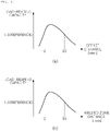
- FIG. 3 is graphs illustrating a relationship between an offset distance S and a load-bearing capacity in a reinforcing member for cold forming or a relationship between a distance G between the welded zones 3 and load-bearing capacity according to an embodiment.
- the graph in FIG. 3(a) indicates the relationship between the offset distance S from the edge E of the reinforcement patch member 2 to the central point C of the welded zone 3 and the load-bearing capacity.
- a central point C may be formed in a position spaced apart from the edge E of the reinforcing patch member 2 in the range of 12 mm-30 mm.
- the offset distance S from the edge E of the reinforcement patch member 2 to the central point C of the welded zone 3 may secure required load-bearing capacity when the distance is in the range of 12mm-30mm.
- a minimum value of the offset distance S, 12 mm may be a value derived by a condition in which a molten nugget may be formed.
- the diameter WD of the welded zone 3 may be 8 mm.
- the heat-affected zone 4 may have the same central point C as the central point C of the welded zone 3, and may form a donut-shaped region with a diameter ZD of 24 mm. In this relationship, the heat-affected zone 4 may be completely formed only when the central point C is formed in a position spaced apart from the edge E of the reinforcing patch member 2 by at least 12 mm. Also, in this case, the molten nugget may be fully formed.
- the maximum value of the offset distance S, 30 mm may be a maximum value for satisfying the reference value of the load-bearing capacity.
- tensile strength of the blank member 1 is 1200 MPa
- a thickness t1 is 1.5 mm
- tensile strength of the reinforcing patch member 2 is 900 MPa
- a thickness t2 is 1.2 mm
- the thickness of the reinforcing member for cold forming formed by coupling the blank member 1 and the reinforcing patch member 2 by the welded zone 3 may be 2.7 mm
- the reference "1" of the load-bearing capacity may become “1070 MPa” under the above conditions. Accordingly, to satisfy the load-bearing capacity of "1070 MPa" or more, the offset distance S should be 30 mm or less.
- the reinforcing member for cold forming may also be limited to the distance G between the welded zones 3 adjacent to each other.
- the position of the first welded zone 3a may also be limited to the distance G with the adjacent second welded zone 3b.
- the central point Ca of the first welded zone 3a should be spaced apart from the central point Cb of the second welded zone 3b with the distance G in the range of 12mm-30mm.
- the central point Ca of the first welded zone 3a is formed in a position further spaced apart from the second welded zone 3b than a position of the case in which the central point Ca of the first welded zone 3a is in contact with the heat-affected component 4 of the neighboring second welded zone 3a or at least the position.
- the problem in which solidification of the molten nugget for forming the first welded zone 3a is delayed by the heat-affected zone 4 of the second welded zone 3b may be addressed. Accordingly, the problem in which the bonding strength of the reinforcing member for cold forming is reduced may be addressed, and the load-bearing capacity of the reinforcing member for cold forming may satisfy the reference value, which may be indicated in the graph in FIG. 3(b) .
- the minimum value of the distance G between the welded zones 3, 12 mm may be the value at which fracture of the first welded zone 3a may be prevented even in a cooling environment under the influence of the heat-affected zone 4 of the second welded zone 3b. That is, it may be assumed that, when the distance G between the welded zones 3 is smaller than 12 mm, more welded zones 3 may be formed, such that the probability of fracture may be reduced. However, on the contrary, the effect of delaying cooling by the heat-affected zone 4 of the second welded zone 3b may increase in the first welded zone 3a, such that the problem of a decrease in bonding strength may also increase. Accordingly, the reinforcing member for cold forming may not secure the load-bearing capacity corresponding to the reference value.
- the diameter WD of the welded zone 3 formed may be 8mm.
- the heat-affected zone 4 may be the same central point C as the central point C of the welded zone 3, and may form a donut-shaped region with a diameter ZD of 24 mm.
- a case in which the distance G between the central points C of the welded zones 3 is 12 mm may be be the minimum distance G satisfying the reference value.
- the maximum value of the distance G between the welded zones 3 of 30mm may be a maximum value for satisfying the reference value of the load-bearing capacity.
- the case in which tensile strength of the blank member 1 is 1200 MPa, the thickness t1 is 1.5 mm, tensile strength of the reinforcing patch member 2 is 900 MPa, and the thickness t2 is 1.2 mm may be as below.
- the reference “1" of the load-bearing capacity may become “1070 MPa” under the above conditions. Accordingly, to satisfy the load-bearing capacity of "1070 MPa" or more, the distance G between the welded zones 3 should be 30 mm or less.
- the entire welded zone 3 forming the reinforcing member for cold forming may be satisfied, and only a portion of the welded zone 3 may be satisfied depending on the shape of the manufactured component. For example, 60% or more of the total number of the welded zones 3 forming the reinforcing member for cold forming may be adjusted to satisfy the above conditions.
- the blank member 1 and the reinforcing patch member 2 have different required tensile strength, which is a reference value required for components manufactured using the reinforcing member for cold forming, the material and tension thereof may be limited to secure the above.
- the blank member 1 or the reinforcing patch member 2 may be provided as one of a steel plate, an aluminum plate, a magnesium plate, and a titanium plate. Also, the blank member 1 and the reinforcing patch member 2 may be provided by a material having tensile strength of 500 MPa to 2500 MPa.
- the welded zone 3 may be formed by spot welding by a welding head. That is, it is suggested that the reinforcing member for cold forming of the embodiment may be manufactured by spot welding applied when a conventional PWB reinforcing member is manufactured.
- a plurality of the welded zones 3 of the reinforcing member for cold forming may be disposed along the edge E shape of the reinforcing patch member 2 and may form an outer row OL.
- the arrangement position of the welded zone 3 to the shape of the edge E of the reinforcement patch member 2 may be limited as above to distribute external force such as an impact force applied to the reinforcement patch member 2 by each welded zone 3.
- a plurality of the welded zones 3 of the reinforcing member for cold forming may be linearly disposed in the outer row OL and may form the inner row IL.
- the welded zone 3 may supplement load-bearing capacity in addition to the tensile strength secured by forming the welded zone 3 in the outer row OL.
- a plurality of the inner row IL may be provided, and accordingly, the effect of supplementing load-bearing capacity may be further increased.
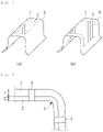
- FIG. 4 is a perspective diagram illustrating a component manufactured using a reinforcing member for cold forming according to an embodiment.
- FIG. 4(a) illustrates an embodiment in which the reinforcing patch member 2 is disposed only on an upper surface of the component.
- FIG. 4 (b) illustrates an embodiment in which the reinforcing patch member 2 is arranged up to a side surface of the component.
- FIG. 5 is a cross-sectional diagram illustrating a bent portion 5 of a component manufactured using a reinforcing member for cold forming according to an embodiment of the present disclosure, viewed from the side.
- the component according to an embodiment may be manufactured by forming the reinforcing member for cold forming at room temperature.
- the cold forming process may refer to forming processes by rolling at room temperature without heating an object (cold rolling), bending processing (cold bending), forging (cold forging, cold heading, and cold press), extrusion (cold extrusion), or the like, differently from a hot forming process in which an object is formed by heating.
- the cold forming process may refer to cold press working in which forming is performed in a product form by reduction at room temperature.
- the component according to an embodiment may be manufactured by forming at least one bent portion 5 on the reinforcing member for cold forming. That is, the component may be formed by bending, pressing, or the like, to form the bent portion 5 among cold forming processes.
- a conventional PWB reinforcing member may have a problem in that most of the welded zone may be fractured when the bent portion is processed by cold processing, whereas the component according to an embodiment may be formed to include the bent portion 5, and may be formed using the reinforcing member for cold forming, fracture of the welded zone 3 may be prevented.
- the bent portion 5 of the component may be formed with a radius of curvature R which may be 2 to 10 times greater than a sum of the thickness t1 of the blank member 1 and the thickness t2 of the reinforcing patch member 2.
- the welded zone 3 disposed adjacent to the bent portion 5 may be fractured.
- the radius of curvature R of the bent portion 5 is greater than the upper limit, the degree of freedom in forming components may be extremely limited.
- specific examples of the components manufactured using the reinforcing member for cold forming may include a collision member such as a side member or center pillar of a vehicle body, a floor lunge member in the underbody of the vehicle body, a floor tunnel, and the like.
- the embodiment relates to a reinforcing member for cold forming and components manufactured using the same, and by improving Patch Worked Blank (PWB) technique among tailoring techniques, fracture of the welded zone 3 may be prevented, and components may be formed by cold process performed at room temperature.
- PWB Patch Worked Blank
- cold forming may be performed without a large space for heating equipment such as in a hot forming process, high initial equipment investment costs, and high operating costs, such that equipment costs and operating costs may be reduced.
- the reinforcing member for cold forming and the components manufactured using the same may reduce limitations on the limited range of curvature radius of the bent portion 5 during cold forming and the limited range of the thickness of the reinforcing patch member 2 may be reduced, such that the degree of freedom in component design may increase.
- the reinforcement member for cold forming and the components manufactured using the same of the embodiment may satisfy performance required for bending collision members among vehicle structural components and may allow the bending collision member to be formed by a cold forming process.
- vehicle structural components may be developed according to various purposes, such as high-strength shape members, high rigidity members, compression collision members, and bending collision members.
- high-strength shape members high rigidity members
- compression collision members compression collision members
- bending collision member internal penetration should be minimized to protect passengers, and fracture should not occur.
- the reinforcing member for cold forming and the components manufactured using the same of the embodiment may be formed by a cold process, which may be the forming at room temperature, and may also satisfy performance required for the bending collision member.
- the center pillar deformation of an upper portion of the center pillar may need to be prevented to protect an upper body of a passenger.
- the upper portion of the center pillar may require relatively high tensile strength as compared to that of the surrounding components.
- the reinforcing member for cold forming of the embodiment may secure such tensile strength, and the manufacturing of the center pillar may be performed at room temperature, such that the reinforcing member may be produced at a lower cost than that of hot processes.
- the hot forming process may be applied to forming a conventional reinforcing member.
- a cold forming process may not have the effect of hot forming process described above, such that a cold forming process may not be applied to the conventional forming of a reinforcing member.
- the reinforcing member for cold forming of the embodiment may satisfy the performance required even in the cold forming process.
Landscapes
- Engineering & Computer Science (AREA)
- Mechanical Engineering (AREA)
- Chemical & Material Sciences (AREA)
- Combustion & Propulsion (AREA)
- Transportation (AREA)
- Architecture (AREA)
- Structural Engineering (AREA)
- Body Structure For Vehicles (AREA)
- Shaping Metal By Deep-Drawing, Or The Like (AREA)
- Resistance Welding (AREA)
Abstract
Description
- The present disclosure relates to a reinforcing member for cold forming and parts manufactured using the same.
- Recently, research into regulations on greenhouse gas emissions and also weight reductions for reducing the weight of eco-friendly vehicles has been conducted. For example, the application of plastics, aluminum, multi-materials has expanded, but there may be a problem in that costs of weight reduction may be relatively high and recycling may be difficult.
- Accordingly, the application of giga-grade steel has been considered, but there may be problems to be solved, such as formability and processing costs.
- The present disclosure is suggested to provide a reinforcing member for cold forming which may prevent damage to welded zones even in cold forming performed at room temperature, and components manufactured using the same.
- A reinforcing member for cold forming according to an embodiment includes a blank member; and a reinforcing patch member provided to cover at least a portion of the blank member and coupled to the blank member by a plurality of welded zones, wherein an entire region of a heat-affected zone formed around the welded zone in the blank member is disposed in a region corresponding to the reinforcing patch member, and a heat-affected zone formed around a first welded zone of the welded zone is in contact with a central point of a second welded zone adjacent to the first welded zone or is spaced apart from the central point of the second welded zone.
- The welded zone has a central point formed in a position spaced apart from an edge of the reinforcing patch member in the range of 12mm-30mm.
- A distance between the first welded zone and the second welded zone may be formed to be within the range of 12mm-30mm.
- The welded zone may be formed by spot welding by a welding head.
- A plurality of the welded zones may be arranged along an edge of the reinforcing patch member and form an outer row.
- A plurality of the welded zones may be arranged linearly on an inner side of the outer row and form an inner row.
- The blank member or the reinforcing patch member may be provided as one of a steel plate, an aluminum plate, a magnesium plate, and a titanium plate.
- The blank member and the reinforcing patch member may be formed of a material having a tensile strength of 500 MPa-2500 MPa.
- A component according to an embodiment may be manufactured by forming a reinforcing member for cold forming at room temperature.
- The component may be manufactured by forming at least one bent portion on the reinforcing member for cold forming.
- The bent portion may be formed with a radius of curvature 2-10 times greater than a sum of a thickness of the blank member and a thickness of the reinforcing patch member.
- The reinforcing member for cold forming of the present disclosure and components manufactured using the same may have an effect of preventing damage to a welded zone even in cold forming performed at room temperature.
- However, the various and beneficial advantages and effects of the present disclosure are not limited to the above, and will be more easily understood in the course of describing specific embodiments of the present disclosure.
-
-
FIG. 1 is a plan diagram illustrating a reinforcing member for cold forming according to an embodiment of the present disclosure. -
FIG. 2 is a plan diagram illustrating portion "A" inFIG. 1 . -
FIG. 3 is graphs illustrating a relationship between an offset distance and a load-bearing capacity in a reinforcing member for cold forming or a relationship between a distance between welded zones and load-bearing capacity according to an embodiment of the present disclosure. -
FIG. 4 is a perspective diagram illustrating a component manufactured using a reinforcing member for cold forming according to an embodiment of the present disclosure. -
FIG. 5 is a cross-sectional diagram illustrating a bent portion of a component manufactured using a reinforcing member for cold forming according to an embodiment of the present disclosure, viewed from the side. - To reduce costs and weight, global mass-produced automobile manufacturers has increasingly applied hot forming steel and cold giga-grade steel.
- Although a hot forming technique has a disadvantage in which heating equipment may occupy a large space and initial equipment investment costs may be high, a hot forming technique may have excellent formability and shape freezing properties as compared to a cold forming technique as a hot forming technique is formed under a high temperature condition with relatively high ductility. However, to reduce costs, research for replacing a hot forming technique with a cold forming technique may be necessary.
- For example, as for a collision member such as a side member or a center pillar of a vehicle body, a tailoring technique which differently combines strength, thickness, or both within a single component to maximize collision performance. Among these tailoring techniques, a patch worked blank (PWB) technique in which a reinforcing patch member is attached to a portion of a blank member by spot welding and forming is performed using a single die has been applied to cold or hot press-formed products . However, in the case of components requiring bending deformation, such as a collision support member for vehicle, a large shear force may be applied to a welded zone by spot welding connecting a blank member and a reinforcing patch member due to a difference in the amount of deformation between the two components, such that the welded zone may be fractured, which may be problematic.
- Particularly, high ductility may not be obtained in cold forming performed at room temperature, the risk of fracture of the welded zone may be greater.
- Accordingly, the present applicant suggests a reinforcing member for cold forming with a small risk of fracture of the welded zone even in cold forming, and components manufactured using the same.
- Hereinafter, an embodiment will be described with reference to the accompanying drawings. However, the embodiment may be modified in various other forms, and the scope of the embodiment is not limited to the embodiment described below. The shapes and sizes of elements in the drawings may be exaggerated for clearer illustration.
- An expression used in the singular encompasses the expression of the plural, unless it has a clearly different meaning in context. Throughout the specification, the same reference characters or reference characters assigned in a similar manner refer to the same or corresponding elements.
-
FIG. 1 is a plan diagram illustrating a reinforcing member for cold forming according to an embodiment.FIG. 2 is a plan diagram illustrating portion "A" inFIG. 1 . Referring thereto, the reinforcing member for cold forming according to an embodiment may include a blank member 1 and a reinforcingpatch member 2. - The reinforcing
patch member 2 may be provided to cover at least a portion of the blank member 1, and may be coupled to the blank member 1 by a plurality ofwelded zones 3. - The
welded zone 3 may formed when the blank member 1 and the reinforcingpatch member 2, which are melted and solidified by a welding head of a welding machine, are coupled to each other. Also, a heat-affected zone (HAZ) may be formed around thewelded zone 3 by heat generated when thewelded zone 3 is formed. The heat-affectedzone 4 may be a zone of which a metal structure or mechanical properties may change due to heat during welding but may not be melted. - The entire region of the heat-affected
zone 4 formed around thewelded zone 3 may be positioned in an area corresponding to the reinforcingpatch member 2. - Also, the heat-affected
zone 4 formed around the firstwelded zone 3a of thewelded zone 3 may be in contact with a central point Cb of a secondwelded zone 3b adjacent to a firstwelded zone 3a, or may be spaced apart from the central point Cb of the second welded zone. Here, the central point C of thewelded zone 3 may be a center of a circle having two points disposed furthest from thewelded zone 3 as a diameter. - To this end, the position of the
welded zone 3 may be limited to an offset distance S, which is a distance from the edge E of thereinforcement patch member 2 to the central point C of thewelded zone 3. - The minimum value of the offset distance S may be limited to a value of when an outermost region of the heat-affected
zone 4 is in contact with an edge E of the reinforcingpatch member 2. - Accordingly, a molten nugget may be stably formed during the formation of the
welded zone 3. Also, bonding force of thewelded zone 3 formed by solidification of the molten nugget may be formed to exceed a required reference value. - As such, the reinforcing member for cold forming according to an embodiment and the component manufactured using the same may, even when being manufactured by cold forming, prevent fracture of the
welded zone 3, and may secure the required load-bearing capacity. -
FIG. 3 is graphs illustrating a relationship between an offset distance S and a load-bearing capacity in a reinforcing member for cold forming or a relationship between a distance G between thewelded zones 3 and load-bearing capacity according to an embodiment. - Specifically, the graph in
FIG. 3(a) indicates the relationship between the offset distance S from the edge E of thereinforcement patch member 2 to the central point C of thewelded zone 3 and the load-bearing capacity. Referring to the graph, in thewelded zone 3 according to an embodiment, a central point C may be formed in a position spaced apart from the edge E of the reinforcingpatch member 2 in the range of 12 mm-30 mm. - As indicated in the graphs, the offset distance S from the edge E of the
reinforcement patch member 2 to the central point C of thewelded zone 3 may secure required load-bearing capacity when the distance is in the range of 12mm-30mm. - Here, a minimum value of the offset distance S, 12 mm, may be a value derived by a condition in which a molten nugget may be formed. For example, when a case in which the diameter of the welding head is 8 mm is applied, the diameter WD of the
welded zone 3 may be 8 mm. The heat-affectedzone 4 may have the same central point C as the central point C of thewelded zone 3, and may form a donut-shaped region with a diameter ZD of 24 mm. In this relationship, the heat-affectedzone 4 may be completely formed only when the central point C is formed in a position spaced apart from the edge E of the reinforcingpatch member 2 by at least 12 mm. Also, in this case, the molten nugget may be fully formed. - The maximum value of the offset distance S, 30 mm, may be a maximum value for satisfying the reference value of the load-bearing capacity. For example, the case in which tensile strength of the blank member 1 is 1200 MPa, a thickness t1 is 1.5 mm, tensile strength of the reinforcing
patch member 2 is 900 MPa, and a thickness t2 is 1.2 mm may be as below. The thickness of the reinforcing member for cold forming formed by coupling the blank member 1 and the reinforcingpatch member 2 by the weldedzone 3 may be 2.7 mm, and tolerable tensile strength may be 1070 MPa ([1200 × 1.5 +900×1.2]/2.7=1070) . That is, in the graph inFIG. 3(a) , the reference "1" of the load-bearing capacity may become "1070 MPa" under the above conditions. Accordingly, to satisfy the load-bearing capacity of "1070 MPa" or more, the offset distance S should be 30 mm or less. - Also, the reinforcing member for cold forming may also be limited to the distance G between the welded
zones 3 adjacent to each other. For example, the position of the first weldedzone 3a may also be limited to the distance G with the adjacent second weldedzone 3b. - Specifically, the central point Ca of the first welded
zone 3a should be spaced apart from the central point Cb of the second weldedzone 3b with the distance G in the range of 12mm-30mm. - This is for the central point Ca of the first welded
zone 3a to be formed in a position further spaced apart from the second weldedzone 3b than a position of the case in which the central point Ca of the first weldedzone 3a is in contact with the heat-affectedcomponent 4 of the neighboring second weldedzone 3a or at least the position. - Accordingly, the problem in which solidification of the molten nugget for forming the first welded
zone 3a is delayed by the heat-affectedzone 4 of the second weldedzone 3b may be addressed. Accordingly, the problem in which the bonding strength of the reinforcing member for cold forming is reduced may be addressed, and the load-bearing capacity of the reinforcing member for cold forming may satisfy the reference value, which may be indicated in the graph inFIG. 3(b) . - Here, the minimum value of the distance G between the welded
zones zone 3a may be prevented even in a cooling environment under the influence of the heat-affectedzone 4 of the second weldedzone 3b. That is, it may be assumed that, when the distance G between the weldedzones 3 is smaller than 12 mm, more weldedzones 3 may be formed, such that the probability of fracture may be reduced. However, on the contrary, the effect of delaying cooling by the heat-affectedzone 4 of the second weldedzone 3b may increase in the first weldedzone 3a, such that the problem of a decrease in bonding strength may also increase. Accordingly, the reinforcing member for cold forming may not secure the load-bearing capacity corresponding to the reference value. - For example, when a case in which the diameter of the welding head is 8mm is applied, the diameter WD of the welded
zone 3 formed may be 8mm. Also, the heat-affectedzone 4 may be the same central point C as the central point C of the weldedzone 3, and may form a donut-shaped region with a diameter ZD of 24 mm. In this case, a case in which the distance G between the central points C of the weldedzones 3 is 12 mm may be be the minimum distance G satisfying the reference value. - Also, the maximum value of the distance G between the welded
zones 3 of 30mm may be a maximum value for satisfying the reference value of the load-bearing capacity. For example, the case in which tensile strength of the blank member 1 is 1200 MPa, the thickness t1 is 1.5 mm, tensile strength of the reinforcingpatch member 2 is 900 MPa, and the thickness t2 is 1.2 mm may be as below. The thickness of the reinforcing member for cold forming formed by coupling the blank member 1 and the reinforcingpatch member 2 by the weldedzone 3 may be 2.7 mm, and tolerable tensile strength may be 1070 MPa ([1200 × 1.5 +900×1.2]/2.7=1070). That is, in the graph inFIG. 3B , the reference "1" of the load-bearing capacity may become "1070 MPa" under the above conditions. Accordingly, to satisfy the load-bearing capacity of "1070 MPa" or more, the distance G between the weldedzones 3 should be 30 mm or less. - Also, under these conditions, the entire welded
zone 3 forming the reinforcing member for cold forming may be satisfied, and only a portion of the weldedzone 3 may be satisfied depending on the shape of the manufactured component. For example, 60% or more of the total number of the weldedzones 3 forming the reinforcing member for cold forming may be adjusted to satisfy the above conditions. - Since the blank member 1 and the reinforcing
patch member 2 have different required tensile strength, which is a reference value required for components manufactured using the reinforcing member for cold forming, the material and tension thereof may be limited to secure the above. - That is, the blank member 1 or the reinforcing
patch member 2 may be provided as one of a steel plate, an aluminum plate, a magnesium plate, and a titanium plate. Also, the blank member 1 and the reinforcingpatch member 2 may be provided by a material having tensile strength of 500 MPa to 2500 MPa. - Here, the welded
zone 3 may be formed by spot welding by a welding head. That is, it is suggested that the reinforcing member for cold forming of the embodiment may be manufactured by spot welding applied when a conventional PWB reinforcing member is manufactured. - Also, a plurality of the welded
zones 3 of the reinforcing member for cold forming according to an embodiment may be disposed along the edge E shape of the reinforcingpatch member 2 and may form an outer row OL. The arrangement position of the weldedzone 3 to the shape of the edge E of thereinforcement patch member 2 may be limited as above to distribute external force such as an impact force applied to thereinforcement patch member 2 by each weldedzone 3. - Also, a plurality of the welded
zones 3 of the reinforcing member for cold forming according to an embodiment may be linearly disposed in the outer row OL and may form the inner row IL. By forming the weldedzone 3 in the inner row IL as above, in the reinforcement member for cold forming, the weldedzone 3 may supplement load-bearing capacity in addition to the tensile strength secured by forming the weldedzone 3 in the outer row OL. A plurality of the inner row IL may be provided, and accordingly, the effect of supplementing load-bearing capacity may be further increased. -
FIG. 4 is a perspective diagram illustrating a component manufactured using a reinforcing member for cold forming according to an embodiment. Here,FIG. 4(a) illustrates an embodiment in which the reinforcingpatch member 2 is disposed only on an upper surface of the component.FIG. 4 (b) illustrates an embodiment in which the reinforcingpatch member 2 is arranged up to a side surface of the component.FIG. 5 is a cross-sectional diagram illustrating abent portion 5 of a component manufactured using a reinforcing member for cold forming according to an embodiment of the present disclosure, viewed from the side. - Referring to the drawings, the component according to an embodiment may be manufactured by forming the reinforcing member for cold forming at room temperature.
- That is, when the reinforcing member for cold forming is used, even when components are produced by a cold forming process, which may be the forming at room temperature, fracture of the welded
zone 3 may be prevented and the required load-bearing capacity may be secured. - Here, the cold forming process may refer to forming processes by rolling at room temperature without heating an object (cold rolling), bending processing (cold bending), forging (cold forging, cold heading, and cold press), extrusion (cold extrusion), or the like, differently from a hot forming process in which an object is formed by heating. Generally, the cold forming process may refer to cold press working in which forming is performed in a product form by reduction at room temperature.
- Also, the component according to an embodiment may be manufactured by forming at least one
bent portion 5 on the reinforcing member for cold forming. That is, the component may be formed by bending, pressing, or the like, to form thebent portion 5 among cold forming processes. - A conventional PWB reinforcing member may have a problem in that most of the welded zone may be fractured when the bent portion is processed by cold processing, whereas the component according to an embodiment may be formed to include the
bent portion 5, and may be formed using the reinforcing member for cold forming, fracture of the weldedzone 3 may be prevented. - The
bent portion 5 of the component according to an embodiment may be formed with a radius of curvature R which may be 2 to 10 times greater than a sum of the thickness t1 of the blank member 1 and the thickness t2 of the reinforcingpatch member 2. - Here, when the radius of curvature R of the
bent portion 5 is smaller than the lower limit value, the weldedzone 3 disposed adjacent to thebent portion 5 may be fractured. Also, when the radius of curvature R of thebent portion 5 is greater than the upper limit, the degree of freedom in forming components may be extremely limited. - Here, specific examples of the components manufactured using the reinforcing member for cold forming may include a collision member such as a side member or center pillar of a vehicle body, a floor lunge member in the underbody of the vehicle body, a floor tunnel, and the like.
- The embodiment relates to a reinforcing member for cold forming and components manufactured using the same, and by improving Patch Worked Blank (PWB) technique among tailoring techniques, fracture of the welded
zone 3 may be prevented, and components may be formed by cold process performed at room temperature. - By using the reinforcing member for cold forming according to an embodiment and the components manufactured using the same, cold forming may be performed without a large space for heating equipment such as in a hot forming process, high initial equipment investment costs, and high operating costs, such that equipment costs and operating costs may be reduced.
- The reinforcing member for cold forming and the components manufactured using the same according to an embodiment may reduce limitations on the limited range of curvature radius of the
bent portion 5 during cold forming and the limited range of the thickness of the reinforcingpatch member 2 may be reduced, such that the degree of freedom in component design may increase. - For example, the reinforcement member for cold forming and the components manufactured using the same of the embodiment may satisfy performance required for bending collision members among vehicle structural components and may allow the bending collision member to be formed by a cold forming process.
- That is, vehicle structural components may be developed according to various purposes, such as high-strength shape members, high rigidity members, compression collision members, and bending collision members. Here, in the bending collision member, internal penetration should be minimized to protect passengers, and fracture should not occur. In this aspect, the reinforcing member for cold forming and the components manufactured using the same of the embodiment may be formed by a cold process, which may be the forming at room temperature, and may also satisfy performance required for the bending collision member.
- For example, as for the center pillar, deformation of an upper portion of the center pillar may need to be prevented to protect an upper body of a passenger. To this end, the upper portion of the center pillar may require relatively high tensile strength as compared to that of the surrounding components. In this aspect, the reinforcing member for cold forming of the embodiment may secure such tensile strength, and the manufacturing of the center pillar may be performed at room temperature, such that the reinforcing member may be produced at a lower cost than that of hot processes.
- That is, in the hot forming process, overall ductility may increase, the load applied to the welded
zone 3 may also be lowered, and the amount of shear deformation may be removed during phase transformation, such that the risk of fracture of the weldedzone 3 may be reduced, and the hot forming process may be applied to forming a conventional reinforcing member. However, a cold forming process may not have the effect of hot forming process described above, such that a cold forming process may not be applied to the conventional forming of a reinforcing member. However, the reinforcing member for cold forming of the embodiment may satisfy the performance required even in the cold forming process.
Claims (11)
- A reinforcing member for cold forming, comprising:a blank member; anda reinforcing patch member provided to cover at least a portion of the blank member and coupled to the blank member by a plurality of welded zones,wherein an entire region of a heat-affected zone formed around the welded zones in the blank member is disposed in a region corresponding to the reinforcing patch member, and a heat-affected zone formed around a first welded zone among the welded zones is in contact with a central point of a second welded zone adjacent to the first welded zone or is spaced apart from the central point of the second welded zone.
- The reinforcing member of claim 1, wherein the welded zone has a central point formed in a position spaced apart from an edge of the reinforcing patch member in the range of 12mm-30mm.
- The reinforcing member of claim 1, wherein a distance between the first welded zone and the second welded zone is formed to be within the range of 12mm-30mm.
- The reinforcing member of claim 1, wherein the welded zone is formed by spot welding by a welding head.
- The reinforcing member of claim 1, wherein a plurality of the welded zones are arranged along an edge of the reinforcing patch member and form an outer row.
- The reinforcing member of claim 5, wherein a plurality of the welded zones are arranged linearly on an inner side of the outer row and form an inner row.
- The reinforcing member of claim 1, wherein the blank member or the reinforcing patch member is provided as one of a steel plate, an aluminum plate, a magnesium plate, and a titanium plate.
- The reinforcing member of claim 1, wherein the blank member and the reinforcing patch member are formed of a material having a tensile strength of 500 MPa-2500 MPa.
- A component manufactured by forming a reinforcing member for cold forming at room temperature of one of claims 1 to 8.
- The component of claim 9, wherein the component is manufactured by forming at least one bent portion on the reinforcing member for cold forming.
- The component of claim 10, wherein the bent portion is formed with a radius of curvature 2-10 times greater than a sum of a thickness of the blank member and a thickness of the reinforcing patch member.
Applications Claiming Priority (2)
| Application Number | Priority Date | Filing Date | Title |
|---|---|---|---|
| KR1020190145220A KR102209607B1 (en) | 2019-11-13 | 2019-11-13 | Reinforced blank for cold forming and manufactured member using thereof |
| PCT/KR2020/015819 WO2021096229A1 (en) | 2019-11-13 | 2020-11-13 | Reinforcing member for cold forming and parts manufactured using same |
Publications (4)
| Publication Number | Publication Date |
|---|---|
| EP4059652A1 true EP4059652A1 (en) | 2022-09-21 |
| EP4059652A4 EP4059652A4 (en) | 2022-12-28 |
| EP4059652B1 EP4059652B1 (en) | 2025-10-01 |
| EP4059652C0 EP4059652C0 (en) | 2025-10-01 |
Family
ID=74239163
Family Applications (1)
| Application Number | Title | Priority Date | Filing Date |
|---|---|---|---|
| EP20888606.9A Active EP4059652B1 (en) | 2019-11-13 | 2020-11-13 | Reinforcing member for cold forming and parts manufactured using same |
Country Status (6)
| Country | Link |
|---|---|
| US (1) | US20220395886A1 (en) |
| EP (1) | EP4059652B1 (en) |
| JP (2) | JP7785668B2 (en) |
| KR (1) | KR102209607B1 (en) |
| CN (1) | CN114728364A (en) |
| WO (1) | WO2021096229A1 (en) |
Family Cites Families (14)
| Publication number | Priority date | Publication date | Assignee | Title |
|---|---|---|---|---|
| KR100361812B1 (en) * | 1998-11-07 | 2003-01-24 | 엘지전자 주식회사 | Welding method of shadow mask and rail for flat CRT |
| JP2000197969A (en) * | 1998-12-25 | 2000-07-18 | Sumitomo Metal Ind Ltd | Integrated molding blank and molding method |
| KR100692723B1 (en) * | 2005-07-26 | 2007-03-09 | 현대자동차주식회사 | Manufacturing method of automotive parts by high temperature simultaneous molding |
| JP4968201B2 (en) * | 2008-07-04 | 2012-07-04 | 住友金属工業株式会社 | Laser welded structural member and manufacturing method thereof |
| EP2617509B1 (en) * | 2010-09-16 | 2023-04-26 | Nippon Steel Corporation | Formed member and manufacturing method thereof |
| JP2012187617A (en) | 2011-03-11 | 2012-10-04 | Nissan Motor Co Ltd | Joined body of high tensile strength steel sheet and resistance welding method for high tensile strength steel sheet |
| KR101737712B1 (en) | 2012-08-10 | 2017-05-18 | 신닛테츠스미킨 카부시키카이샤 | Lap welded member, automobile component, method for welding lapped part, and method for manufacturing lap welded member |
| KR101360661B1 (en) * | 2012-12-21 | 2014-02-10 | 주식회사 포스코 | Hot stamping member having connecting structure of tailored blank |
| JP6191263B2 (en) * | 2013-06-17 | 2017-09-06 | 新日鐵住金株式会社 | Lap welded member and manufacturing method thereof |
| DE102013012478A1 (en) * | 2013-07-26 | 2015-01-29 | GM Global Technology Operations LLC (n. d. Gesetzen des Staates Delaware) | Body component and method for producing a body component |
| JP6209991B2 (en) | 2014-03-03 | 2017-10-11 | 新日鐵住金株式会社 | Blank material manufacturing method, hot stamp molded product manufacturing method, blank material, and hot stamp molded product |
| JP6451327B2 (en) * | 2015-01-08 | 2019-01-16 | 新日鐵住金株式会社 | Overlapping blank for hot stamping, method for manufacturing overlapping hot stamping molded body, and overlapping hot stamping molded body |
| JP6624189B2 (en) * | 2017-12-04 | 2019-12-25 | マツダ株式会社 | Body member manufacturing method and vehicle body member |
| CN109048110A (en) * | 2018-09-27 | 2018-12-21 | 舞钢神州重工金属复合材料有限公司 | Wide format ferritic stainless steel Explosive Welding production technology |
-
2019
- 2019-11-13 KR KR1020190145220A patent/KR102209607B1/en active Active
-
2020
- 2020-11-13 EP EP20888606.9A patent/EP4059652B1/en active Active
- 2020-11-13 CN CN202080078126.4A patent/CN114728364A/en active Pending
- 2020-11-13 US US17/771,986 patent/US20220395886A1/en active Pending
- 2020-11-13 JP JP2022525724A patent/JP7785668B2/en active Active
- 2020-11-13 WO PCT/KR2020/015819 patent/WO2021096229A1/en not_active Ceased
-
2025
- 2025-08-07 JP JP2025132179A patent/JP2025160488A/en active Pending
Also Published As
| Publication number | Publication date |
|---|---|
| JP2023501962A (en) | 2023-01-20 |
| JP2025160488A (en) | 2025-10-22 |
| CN114728364A (en) | 2022-07-08 |
| EP4059652A4 (en) | 2022-12-28 |
| JP7785668B2 (en) | 2025-12-15 |
| KR102209607B1 (en) | 2021-01-28 |
| EP4059652B1 (en) | 2025-10-01 |
| WO2021096229A1 (en) | 2021-05-20 |
| EP4059652C0 (en) | 2025-10-01 |
| US20220395886A1 (en) | 2022-12-15 |
Similar Documents
| Publication | Publication Date | Title |
|---|---|---|
| US12202025B2 (en) | Press-formed article, press-forming method, and press-forming apparatus | |
| US10239105B2 (en) | Blank steel plate, production method and production device therefor, and production method for press-formed product using blank steel plate | |
| US20140144973A1 (en) | Reinforcing structure for reinforcing a side wall structure for a motor vehicle in the region of a door cutout | |
| US20180029645A1 (en) | Longitudinal beam made of multi-layer steel | |
| US20170291208A1 (en) | Producing method, producing apparatus and producing equipment line of press formed product | |
| JP7705384B2 (en) | Vehicle floor and corresponding manufacturing method - Patents.com | |
| JP6588972B2 (en) | Reinforcing elements for automobiles, methods for manufacturing reinforcing elements and door assemblies | |
| EP3390206B1 (en) | B-pillar central beam and method for manufacturing | |
| US20090155615A1 (en) | Designed orientation for welded automotive structural components made of press hardened steel | |
| KR102513658B1 (en) | Bumper beam with insert | |
| US10017210B2 (en) | Spring strut dome and method for producing same | |
| KR20130055016A (en) | Molded member and manufacturing method thereof | |
| CA2990571C (en) | Bumper reinforcement and vehicle including the same | |
| EP4190646A1 (en) | Structural member for automobile body | |
| CN120457069A (en) | Integral roof ring for vehicle frame | |
| CN108367785B (en) | Hardened UHSS structural beam with stiffeners and method of manufacture | |
| JP7590700B2 (en) | Manufacturing method of press-molded products | |
| EP4059652B1 (en) | Reinforcing member for cold forming and parts manufactured using same | |
| CN109982918A (en) | The stiffener of sheet shaped piece including clod wash | |
| CN118019682A (en) | Floor panel and method for vehicle | |
| JP2009035244A (en) | Roof reinforcement material for automotive body | |
| TWI791637B (en) | Method for manufacturing a cold rolled member | |
| WO2025181516A1 (en) | Reinforcement insert for a vehicle side structure |
Legal Events
| Date | Code | Title | Description |
|---|---|---|---|
| STAA | Information on the status of an ep patent application or granted ep patent |
Free format text: STATUS: THE INTERNATIONAL PUBLICATION HAS BEEN MADE |
|
| PUAI | Public reference made under article 153(3) epc to a published international application that has entered the european phase |
Free format text: ORIGINAL CODE: 0009012 |
|
| STAA | Information on the status of an ep patent application or granted ep patent |
Free format text: STATUS: REQUEST FOR EXAMINATION WAS MADE |
|
| 17P | Request for examination filed |
Effective date: 20220519 |
|
| AK | Designated contracting states |
Kind code of ref document: A1 Designated state(s): AL AT BE BG CH CY CZ DE DK EE ES FI FR GB GR HR HU IE IS IT LI LT LU LV MC MK MT NL NO PL PT RO RS SE SI SK SM TR |
|
| A4 | Supplementary search report drawn up and despatched |
Effective date: 20221128 |
|
| RIC1 | Information provided on ipc code assigned before grant |
Ipc: B62D 29/00 20060101ALI20221122BHEP Ipc: B23K 103/18 20060101ALI20221122BHEP Ipc: B23K 103/08 20060101ALI20221122BHEP Ipc: B23K 103/14 20060101ALI20221122BHEP Ipc: B23K 103/10 20060101ALI20221122BHEP Ipc: B23K 103/04 20060101ALI20221122BHEP Ipc: B23K 101/18 20060101ALI20221122BHEP Ipc: B23K 101/00 20060101ALI20221122BHEP Ipc: B23K 31/02 20060101ALI20221122BHEP Ipc: B62D 21/15 20060101ALI20221122BHEP Ipc: B62D 25/20 20060101ALI20221122BHEP Ipc: B62D 25/04 20060101ALI20221122BHEP Ipc: B62D 21/02 20060101ALI20221122BHEP Ipc: B21D 22/00 20060101ALI20221122BHEP Ipc: B23K 11/00 20060101AFI20221122BHEP |
|
| DAV | Request for validation of the european patent (deleted) | ||
| DAX | Request for extension of the european patent (deleted) | ||
| GRAP | Despatch of communication of intention to grant a patent |
Free format text: ORIGINAL CODE: EPIDOSNIGR1 |
|
| STAA | Information on the status of an ep patent application or granted ep patent |
Free format text: STATUS: GRANT OF PATENT IS INTENDED |
|
| RIC1 | Information provided on ipc code assigned before grant |
Ipc: B62D 29/00 20060101ALI20250403BHEP Ipc: B23K 103/18 20060101ALI20250403BHEP Ipc: B23K 103/08 20060101ALI20250403BHEP Ipc: B23K 103/14 20060101ALI20250403BHEP Ipc: B23K 103/10 20060101ALI20250403BHEP Ipc: B23K 103/04 20060101ALI20250403BHEP Ipc: B23K 101/18 20060101ALI20250403BHEP Ipc: B23K 101/00 20060101ALI20250403BHEP Ipc: B23K 31/02 20060101ALI20250403BHEP Ipc: B62D 21/15 20060101ALI20250403BHEP Ipc: B62D 25/20 20060101ALI20250403BHEP Ipc: B62D 25/04 20060101ALI20250403BHEP Ipc: B62D 21/02 20060101ALI20250403BHEP Ipc: B21D 22/00 20060101ALI20250403BHEP Ipc: B23K 11/00 20060101AFI20250403BHEP |
|
| INTG | Intention to grant announced |
Effective date: 20250428 |
|
| GRAS | Grant fee paid |
Free format text: ORIGINAL CODE: EPIDOSNIGR3 |
|
| GRAA | (expected) grant |
Free format text: ORIGINAL CODE: 0009210 |
|
| STAA | Information on the status of an ep patent application or granted ep patent |
Free format text: STATUS: THE PATENT HAS BEEN GRANTED |
|
| AK | Designated contracting states |
Kind code of ref document: B1 Designated state(s): AL AT BE BG CH CY CZ DE DK EE ES FI FR GB GR HR HU IE IS IT LI LT LU LV MC MK MT NL NO PL PT RO RS SE SI SK SM TR |
|
| REG | Reference to a national code |
Ref country code: GB Ref legal event code: FG4D Ref country code: CH Ref legal event code: F10 Free format text: ST27 STATUS EVENT CODE: U-0-0-F10-F00 (AS PROVIDED BY THE NATIONAL OFFICE) Effective date: 20251001 |
|
| REG | Reference to a national code |
Ref country code: IE Ref legal event code: FG4D |
|
| REG | Reference to a national code |
Ref country code: DE Ref legal event code: R096 Ref document number: 602020059921 Country of ref document: DE |
|
| U01 | Request for unitary effect filed |
Effective date: 20251029 |
|
| U07 | Unitary effect registered |
Designated state(s): AT BE BG DE DK EE FI FR IT LT LU LV MT NL PT RO SE SI Effective date: 20251104 |
|
| U20 | Renewal fee for the european patent with unitary effect paid |
Year of fee payment: 6 Effective date: 20251029 |
|
| PG25 | Lapsed in a contracting state [announced via postgrant information from national office to epo] |
Ref country code: ES Free format text: LAPSE BECAUSE OF FAILURE TO SUBMIT A TRANSLATION OF THE DESCRIPTION OR TO PAY THE FEE WITHIN THE PRESCRIBED TIME-LIMIT Effective date: 20251001 |
|
| PG25 | Lapsed in a contracting state [announced via postgrant information from national office to epo] |
Ref country code: NO Free format text: LAPSE BECAUSE OF FAILURE TO SUBMIT A TRANSLATION OF THE DESCRIPTION OR TO PAY THE FEE WITHIN THE PRESCRIBED TIME-LIMIT Effective date: 20260101 |
|
| PG25 | Lapsed in a contracting state [announced via postgrant information from national office to epo] |
Ref country code: HR Free format text: LAPSE BECAUSE OF FAILURE TO SUBMIT A TRANSLATION OF THE DESCRIPTION OR TO PAY THE FEE WITHIN THE PRESCRIBED TIME-LIMIT Effective date: 20251001 |
|
| PG25 | Lapsed in a contracting state [announced via postgrant information from national office to epo] |
Ref country code: RS Free format text: LAPSE BECAUSE OF FAILURE TO SUBMIT A TRANSLATION OF THE DESCRIPTION OR TO PAY THE FEE WITHIN THE PRESCRIBED TIME-LIMIT Effective date: 20260101 |
|
| PG25 | Lapsed in a contracting state [announced via postgrant information from national office to epo] |
Ref country code: IS Free format text: LAPSE BECAUSE OF FAILURE TO SUBMIT A TRANSLATION OF THE DESCRIPTION OR TO PAY THE FEE WITHIN THE PRESCRIBED TIME-LIMIT Effective date: 20260201 |
|
| PG25 | Lapsed in a contracting state [announced via postgrant information from national office to epo] |
Ref country code: CZ Free format text: LAPSE BECAUSE OF FAILURE TO SUBMIT A TRANSLATION OF THE DESCRIPTION OR TO PAY THE FEE WITHIN THE PRESCRIBED TIME-LIMIT Effective date: 20251001 |
|
| PG25 | Lapsed in a contracting state [announced via postgrant information from national office to epo] |
Ref country code: PL Free format text: LAPSE BECAUSE OF FAILURE TO SUBMIT A TRANSLATION OF THE DESCRIPTION OR TO PAY THE FEE WITHIN THE PRESCRIBED TIME-LIMIT Effective date: 20251001 |