EP4059551A1 - Pharmaceutical drug delivery device, and method of air flow and humidity control thereof - Google Patents
Pharmaceutical drug delivery device, and method of air flow and humidity control thereof Download PDFInfo
- Publication number
- EP4059551A1 EP4059551A1 EP22160661.9A EP22160661A EP4059551A1 EP 4059551 A1 EP4059551 A1 EP 4059551A1 EP 22160661 A EP22160661 A EP 22160661A EP 4059551 A1 EP4059551 A1 EP 4059551A1
- Authority
- EP
- European Patent Office
- Prior art keywords
- fluid
- drug delivery
- delivery device
- jet ejection
- fluid jet
- Prior art date
- Legal status (The legal status is an assumption and is not a legal conclusion. Google has not performed a legal analysis and makes no representation as to the accuracy of the status listed.)
- Withdrawn
Links
Images


Classifications
-
- A—HUMAN NECESSITIES
- A61—MEDICAL OR VETERINARY SCIENCE; HYGIENE
- A61M—DEVICES FOR INTRODUCING MEDIA INTO, OR ONTO, THE BODY; DEVICES FOR TRANSDUCING BODY MEDIA OR FOR TAKING MEDIA FROM THE BODY; DEVICES FOR PRODUCING OR ENDING SLEEP OR STUPOR
- A61M11/00—Sprayers or atomisers specially adapted for therapeutic purposes
- A61M11/005—Sprayers or atomisers specially adapted for therapeutic purposes using ultrasonics
-
- A—HUMAN NECESSITIES
- A61—MEDICAL OR VETERINARY SCIENCE; HYGIENE
- A61M—DEVICES FOR INTRODUCING MEDIA INTO, OR ONTO, THE BODY; DEVICES FOR TRANSDUCING BODY MEDIA OR FOR TAKING MEDIA FROM THE BODY; DEVICES FOR PRODUCING OR ENDING SLEEP OR STUPOR
- A61M15/00—Inhalators
- A61M15/02—Inhalators with activated or ionised fluids, e.g. electrohydrodynamic [EHD] or electrostatic devices; Ozone-inhalators with radioactive tagged particles
- A61M15/025—Bubble jet droplet ejection devices
-
- A—HUMAN NECESSITIES
- A61—MEDICAL OR VETERINARY SCIENCE; HYGIENE
- A61M—DEVICES FOR INTRODUCING MEDIA INTO, OR ONTO, THE BODY; DEVICES FOR TRANSDUCING BODY MEDIA OR FOR TAKING MEDIA FROM THE BODY; DEVICES FOR PRODUCING OR ENDING SLEEP OR STUPOR
- A61M11/00—Sprayers or atomisers specially adapted for therapeutic purposes
- A61M11/02—Sprayers or atomisers specially adapted for therapeutic purposes operated by air or other gas pressure applied to the liquid or other product to be sprayed or atomised
-
- A—HUMAN NECESSITIES
- A61—MEDICAL OR VETERINARY SCIENCE; HYGIENE
- A61M—DEVICES FOR INTRODUCING MEDIA INTO, OR ONTO, THE BODY; DEVICES FOR TRANSDUCING BODY MEDIA OR FOR TAKING MEDIA FROM THE BODY; DEVICES FOR PRODUCING OR ENDING SLEEP OR STUPOR
- A61M11/00—Sprayers or atomisers specially adapted for therapeutic purposes
- A61M11/04—Sprayers or atomisers specially adapted for therapeutic purposes operated by the vapour pressure of the liquid to be sprayed or atomised
- A61M11/041—Sprayers or atomisers specially adapted for therapeutic purposes operated by the vapour pressure of the liquid to be sprayed or atomised using heaters
-
- A—HUMAN NECESSITIES
- A61—MEDICAL OR VETERINARY SCIENCE; HYGIENE
- A61M—DEVICES FOR INTRODUCING MEDIA INTO, OR ONTO, THE BODY; DEVICES FOR TRANSDUCING BODY MEDIA OR FOR TAKING MEDIA FROM THE BODY; DEVICES FOR PRODUCING OR ENDING SLEEP OR STUPOR
- A61M15/00—Inhalators
- A61M15/0001—Details of inhalators; Constructional features thereof
- A61M15/0021—Mouthpieces therefor
- A61M15/0025—Mouthpieces therefor with caps
-
- A—HUMAN NECESSITIES
- A61—MEDICAL OR VETERINARY SCIENCE; HYGIENE
- A61M—DEVICES FOR INTRODUCING MEDIA INTO, OR ONTO, THE BODY; DEVICES FOR TRANSDUCING BODY MEDIA OR FOR TAKING MEDIA FROM THE BODY; DEVICES FOR PRODUCING OR ENDING SLEEP OR STUPOR
- A61M15/00—Inhalators
- A61M15/0028—Inhalators using prepacked dosages, one for each application, e.g. capsules to be perforated or broken-up
-
- A—HUMAN NECESSITIES
- A61—MEDICAL OR VETERINARY SCIENCE; HYGIENE
- A61M—DEVICES FOR INTRODUCING MEDIA INTO, OR ONTO, THE BODY; DEVICES FOR TRANSDUCING BODY MEDIA OR FOR TAKING MEDIA FROM THE BODY; DEVICES FOR PRODUCING OR ENDING SLEEP OR STUPOR
- A61M15/00—Inhalators
- A61M15/0085—Inhalators using ultrasonics
-
- A—HUMAN NECESSITIES
- A61—MEDICAL OR VETERINARY SCIENCE; HYGIENE
- A61M—DEVICES FOR INTRODUCING MEDIA INTO, OR ONTO, THE BODY; DEVICES FOR TRANSDUCING BODY MEDIA OR FOR TAKING MEDIA FROM THE BODY; DEVICES FOR PRODUCING OR ENDING SLEEP OR STUPOR
- A61M15/00—Inhalators
- A61M15/0086—Inhalation chambers
-
- A—HUMAN NECESSITIES
- A61—MEDICAL OR VETERINARY SCIENCE; HYGIENE
- A61M—DEVICES FOR INTRODUCING MEDIA INTO, OR ONTO, THE BODY; DEVICES FOR TRANSDUCING BODY MEDIA OR FOR TAKING MEDIA FROM THE BODY; DEVICES FOR PRODUCING OR ENDING SLEEP OR STUPOR
- A61M15/00—Inhalators
- A61M15/08—Inhaling devices inserted into the nose
-
- A—HUMAN NECESSITIES
- A61—MEDICAL OR VETERINARY SCIENCE; HYGIENE
- A61M—DEVICES FOR INTRODUCING MEDIA INTO, OR ONTO, THE BODY; DEVICES FOR TRANSDUCING BODY MEDIA OR FOR TAKING MEDIA FROM THE BODY; DEVICES FOR PRODUCING OR ENDING SLEEP OR STUPOR
- A61M2206/00—Characteristics of a physical parameter; associated device therefor
- A61M2206/10—Flow characteristics
-
- A—HUMAN NECESSITIES
- A61—MEDICAL OR VETERINARY SCIENCE; HYGIENE
- A61M—DEVICES FOR INTRODUCING MEDIA INTO, OR ONTO, THE BODY; DEVICES FOR TRANSDUCING BODY MEDIA OR FOR TAKING MEDIA FROM THE BODY; DEVICES FOR PRODUCING OR ENDING SLEEP OR STUPOR
- A61M2210/00—Anatomical parts of the body
- A61M2210/06—Head
- A61M2210/0618—Nose
Definitions
- the disclosure is directed to inhalation drug delivery systems and in particular to inhalation devices that have improved air flow and humidity control.
- Nasal spray devices have become important methods for delivering drugs to patients. Such nasal spray devices are more convenient to use than the administration of drugs through IV or injection. Nasal spray devices also provide higher bioavailability of drugs compared to oral administration of drugs. The absorption of drugs through nasal spray devices is more rapid compared to the absorption of drugs administered orally since drugs delivered by nasal spray devices directly enter the blood stream making their effect more immediate.
- FIG. 1 is a cross sectional view, not to scale, of anatomy of a nasal cavity 10 of a person.
- a portion of the brain 12 is shown above the nasal cavity 10.
- An olfactory bulb 14 is disposed between the brain 12 and a cribriform plate 16.
- An olfactory mucosa 18 is below the cribriform plate 16.
- the nasal cavity also includes a superior turbinate 20, a middle turbinate 22, respiratory mucosa 24 and an inferior turbinate 26.
- Item 28 represents the palate. Injection of a pharmaceutical drug mist enters the nasal cavity 10 through the nostrils 30 and squamous mucosa 32.
- the drugs In order to achieve proper delivery of drugs to the blood stream using a nasal spray device, the drugs must be delivered to the respiratory mucosa which is highly vascularized. Two areas that are highly vascularized are the olfactory region and the respiratory region. The respiratory region contains turbinates which increase the surface area available for drug absorption.
- Conventional methods for delivering drugs via the nasal cavity include medicine droppers, multi-spray bottles with spray tips, single-dose syringes with spray tips, and dry powder systems. Accordingly, conventional drug delivery devices are typically designed to deliver a specific drug to a nasal cavity and each device cannot be adapted for delivering a wide range of drugs via a nasal cavity route. Many of the conventional methods for nasal drug delivery rely on pressurized containers to inject a mist of fluid into the nasal cavity. Accordingly, the drug delivery devices are typically designed for a specific drug and cannot be adapted to administer a different drug.
- a nasal drug delivery device that can be adapted to deliver a variety of drugs.
- One such device is an on-demand fluid jet delivery device.
- Conventional fluid jet delivery devices operate to eject fluid to a substrate under ambient atmospheric pressure.
- a nozzle of a nasal applicator is used, the nozzle is inserted into one nostril of a user which closes off the nostril to the ambient atmosphere.
- a low pressure area is generated in the nozzle of the device.
- the nasal applicator uses a fluid jet delivery ejection head attached to a fluid cartridge
- the low pressure will provide a pressure differential that will cause fluid inside of fluid cartridge to drool out of the ejection head and puddle on the surface thereof.
- Such fluid puddling interferes with fluid jetting from the ejection head and delivery of a precise amount of pharmaceutical drug to the user.
- Another problem associated with using a fluid jet ejector device to administer drugs to a user's nasal cavity is that fluid may dry out on the ejection head between uses and interfere with fluid ejected through fluid nozzles on the ejection head causing misdirection of fluid and mis-firing of fluid ejectors. Accordingly, what is needed is an improved nasal applicator that is designed to prevent drooling of fluid from a fluid cartridge having a fluid jet delivery device to eject fluid into a nasal cavity of a user. The device must also prevent fluid from drying out on the ejection head between uses of the device.
- an embodiment of the disclosure provides a pharmaceutical drug delivery device and method of preventing drying out and drooling of an ejection head for the drug delivery device.
- the device includes a drug delivery device body; a fluid outlet nozzle attached to the drug delivery device body; and a fluid jet ejection cartridge containing a liquid pharmaceutical drug disposed in the drug delivery device body.
- a fluid jet ejection head is attached to the fluid jet ejection cartridge and the fluid jet ejection head is in fluid flow communication with the fluid outlet nozzle.
- An elongate, serpentine air flow path is provided between an outer surface of the fluid jet ejection cartridge and an inner surface of the fluid outlet nozzle. The elongate, serpentine air flow path provides a reduced pressure differential adjacent to a surface of the fluid jet ejection head upon use of the pharmaceutical drug delivery device and provides a humidification zone.
- a method for reducing a pressure differential on a fluid jet ejection head for a nasal spray device includes providing a pharmaceutical drug delivery device having a fluid outlet nozzle attached to a drug delivery device body; a fluid jet ejection cartridge disposed in the drug delivery device body, the fluid jet ejection cartridge containing the fluid jet ejection head in fluid flow communication with the fluid outlet nozzle and a pharmaceutical drug in the fluid jet ejection cartridge.
- a sealing material is inserted between an outer surface of the fluid jet ejection cartridge and an inner surface of the fluid outlet nozzle.
- the sealing material contains an elongate, serpentine air flow path therein to provide a reduced pressure differential adjacent to a surface of the fluid jet ejection head upon use of the pharmaceutical drug delivery device.
- the nasal spray device is activated while flowing air through the drug delivery device body and elongate, serpentine air flow path when the fluid outlet nozzle is inserted into the nasal passage of a user thereby preventing fluid from drooling from the fluid jet ejection head.
- a method for preventing a surface of a fluid jet ejection head for a nasal spray device from drying out between uses includes providing a pharmaceutical drug delivery device having a fluid outlet nozzle attached to a drug delivery device body; a fluid jet ejection cartridge disposed in the drug delivery device body, the fluid jet ejection cartridge containing the fluid jet ejection head in fluid flow communication with the fluid outlet nozzle and a pharmaceutical drug in the fluid jet ejection cartridge.
- a sealing material is inserted between an outer surface of the fluid jet ejection cartridge and an inner surface of the fluid outlet nozzle.
- the sealing material contains an elongate, serpentine air flow path therein to provide a humidification zone in the pharmaceutical drug delivery device adjacent to a surface of the fluid jet ejection head between uses of the pharmaceutical drug delivery device.
- the fluid outlet nozzle is plugged with a cap to prevent drying out of the surface of the fluid jet ejection head.
- the elongate, serpentine air flow path has a length to cross-sectional area ratio of about 30 : 1 to about 100 : 1.
- the elongate, serpentine air flow path is provided by a multi-chamber sealing material disposed in the fluid outlet nozzle between an interior surface of the fluid outlet nozzle and an exterior surface of the fluid jet ejection cartridge, wherein the multi-chamber sealing material includes air chambers and notches for air flow between adjacent air chambers.
- the elongate, serpentine air flow path is provided between an exterior surface of the fluid jet ejection cartridge and the air chambers of the multi-chamber sealing material.
- the elongate, serpentine air flow path is provided between the interior surface of the fluid outlet nozzle and an exterior surface of a sealing material disposed in the fluid outlet nozzle adjacent to the fluid jet ejection cartridge.
- a plug is provided to cap off the fluid outlet nozzle and create the humidification zone in the pharmaceutical drug delivery device between uses.
- An advantage of disclosed embodiments is that a single sealing material can be used to provide both reduced pressure differential on a jet ejection head during use of the pharmaceutical device and can provide a humidification zone in the device when capped to prevent the ejection head from drying out.
- the pharmaceutical drug delivery device 100 includes a drug delivery device body 102, having a fluid outlet nozzle 104 attached to the drug delivery device body 102.
- a power button 106 is provided to activate the drug delivery device as indicated by an LED 108.
- a dispense button 110 is pressed and fluid delivery is indicated by LED's 112.
- a plug 114 may be inserted into the device 100 to prevent fluid from drying out on a fluid jet ejection head used to deliver the pharmaceutical drug to a user.
- the drug delivery device body 102 also contains a power source and a controller for controlling the ejection of fluid from the fluid jet ejection head.
- the pharmaceutical drug delivery device 100 includes the drug delivery device body 102 for holding a fluid jet ejection cartridge 116 containing a pharmaceutical fluid 118 in a cartridge holder 120.
- a fluid filter 122 is disposed in the fluid jet ejection cartridge 116 to filter the fluid flowing through filter tower structures 124 to a fluid jet ejection head 126.
- the fluid jet ejection cartridge 116 may also contain a backpressure control device such as a bladder or foam for inducing a backpressure on the fluid jet ejection head 126.
- the fluid jet ejection head 126 may be selected from any of the conventional types of fluid jet ejection heads, including but not limited to, thermal jet ejection heads, bubble jet ejection heads, piezoelectric jet ejection heads, and the like. Each of the foregoing ejection heads can produce a spray of fluid on demand.
- a low pressure area is formed adjacent to an exposed surface 128 of the fluid jet ejection head 126.
- This low pressure area creates a "pressure differential" between the exposed surface 128 of the fluid jet ejection head 126 and the fluid in the fluid jet ejection cartridge 116.
- the pressure differential can cause unwanted flow or drooling of fluid from the fluid jet ejection head 126.
- a sealing material 130 containing a serpentine air flow path 132 is provided in the fluid outlet nozzle 104 surrounding the fluid jet ejection cartridge 116.
- the sealing material 130 contains alternating notches 134 that are in fluid flow communication with adjacent air chambers 136 so that a serpentine path through the sealing material 130 is provided.
- the sealing material for use with the pharmaceutical drug delivery device 100 may be selected from a wide variety of sulfur-free resilient materials such as natural or synthetic rubber, and thermoplastic or thermoset elastomers having a shore A durometer of less than about 60 that are compatible with the fluids being ejected from the fluid jet ejection head 126.
- sulfur-free resilient materials such as natural or synthetic rubber, and thermoplastic or thermoset elastomers having a shore A durometer of less than about 60 that are compatible with the fluids being ejected from the fluid jet ejection head 126.
- examples of such materials include, but are not limited to natural rubber, EPDM rubber, and a dynamically vulcanized alloy consisting mostly of fully cured EPDM rubber particles encapsulated in a polypropylene (PP) matrix, available from ExxonMobil under the tradename SANTOPRENE.
- PP polypropylene
- the sealing material 130 can be molded and shaped to provide the serpentine air flow path 132 therein and can provide a seal between the fluid jet ejection cartridge 116 and the fluid outlet nozzle 104. It will be appreciated that the drug delivery device body 102 of the pharmaceutical drug delivery device 100 is not air-tight and thus provides inlet air flows from a variety of locations such as from the buttons 106 and 110 and any opening provided for inserting the fluid jet ejection cartridge 116 into the drug delivery device body 102.
- the chambers 136 provide areas for holding humid air so that any fluid on the exposed surface 128 of the fluid jet ejection head 126 is less likely to dry out between uses of the pharmaceutical drug delivery device 100.
- chambers 136 provide humidification zones in the fluid outlet nozzle 104 of the pharmaceutical drug delivery device 100 when capped.
- FIGs. 5 and 6 provide more details of the sealing material 130 and air flow path 132 through the sealing material 130.
- the sealing material 130 contains a plurality of separators 140 that divide the sealing material into the chambers 136A-C illustrated in FIG. 6 .
- Each of the separators 140 has a notch 142 therein, wherein the notches 142 in adjacent separators 140 are on opposite sides of the fluid jet ejection cartridge 116 thereby providing the serpentine air flow path 132 around the fluid jet ejection cartridge 116.
- the sealing material 130 contains at least three separators 140 providing three chambers 136A-C.
- the sealing material contains a serpentine air flow path that devoid of the air chambers and notches and is selected to have a much greater length than the cross-sectional air flow area of the flow path.
- the serpentine air flow path has a length to area ratio ranging from about 30 : 1 to about 100 : 1, such as from about 35 :1 to about 60 : 1.
- FIGs. 7 and 8 An alternative configuration of a sealing material 150 for the pharmaceutical drug delivery device 100 is illustrated in FIGs. 7 and 8 .
- the sealing material 150 contains one or more serpentine air flow paths 152 adjacent to the fluid jet ejection cartridge 116 rather than the separators 140 and chambers 136 described above. At least two serpentine air flow paths 152 are provided in sealing material 150, and the two serpentine air flow paths 152 are on opposite sides of the fluid jet ejection cartridge 116.
- the sealing material 150 may contain three or four serpentine air flow paths 152 around the inside circumference thereof.
- the elongate serpentine air flow paths may be positioned on an exterior surface of the sealing material rather than on an inside surface adjacent to the fluid jet ejection cartridge 116.
- FIGs. 9-12 illustrate alternative embodiments for sealing materials 160 and 170.
- the sealing material 160 includes separator rings 162 having alternating notches 164 therein to provide chambers 166A-166D between the separator rings 162. Accordingly, the notches 164 may be on opposite sides of the sealing material 160 in order to provide a serpentine path for air flow in the fluid outlet nozzle 104 between an exterior surface 166 of the sealing material 160 and an interior surface 168 of the fluid outlet nozzle 104.
- the sealing material 170 includes serpentine paths 172 on opposing sides of the sealing material 170.
- the serpentine paths 172 are disposed between an inside surface 168 of the fluid outlet nozzle 104 and an outside surface 174 of the sealing material 170.
- Two serpentine paths 172 are illustrated in FIG. 12 , however, the sealing material 170 may contain up to four serpentine paths 172 around a circumference of the sealing material 170.
- the sealing materials 150 and 170 contain serpentine air flow paths 152 and 172, respectively, that are devoid of the air chambers and notches and are selected to have much greater lengths than the cross-sectional air flow areas of the air flow paths.
- the serpentine air flow paths have a length to area ratio ranging from about 30 : 1 to about 100 : 1, such as from about 35 :1 to about 60 : 1.
Landscapes
- Health & Medical Sciences (AREA)
- Engineering & Computer Science (AREA)
- Life Sciences & Earth Sciences (AREA)
- Biomedical Technology (AREA)
- Heart & Thoracic Surgery (AREA)
- Hematology (AREA)
- Anesthesiology (AREA)
- Animal Behavior & Ethology (AREA)
- General Health & Medical Sciences (AREA)
- Public Health (AREA)
- Veterinary Medicine (AREA)
- Bioinformatics & Cheminformatics (AREA)
- Pulmonology (AREA)
- Otolaryngology (AREA)
- Infusion, Injection, And Reservoir Apparatuses (AREA)
Abstract
Description
- The disclosure is directed to inhalation drug delivery systems and in particular to inhalation devices that have improved air flow and humidity control.
- Nasal spray devices have become important methods for delivering drugs to patients. Such nasal spray devices are more convenient to use than the administration of drugs through IV or injection. Nasal spray devices also provide higher bioavailability of drugs compared to oral administration of drugs. The absorption of drugs through nasal spray devices is more rapid compared to the absorption of drugs administered orally since drugs delivered by nasal spray devices directly enter the blood stream making their effect more immediate.
-
FIG. 1 is a cross sectional view, not to scale, of anatomy of anasal cavity 10 of a person. A portion of thebrain 12 is shown above thenasal cavity 10. Anolfactory bulb 14 is disposed between thebrain 12 and acribriform plate 16. Anolfactory mucosa 18 is below thecribriform plate 16. The nasal cavity also includes asuperior turbinate 20, amiddle turbinate 22,respiratory mucosa 24 and aninferior turbinate 26.Item 28 represents the palate. Injection of a pharmaceutical drug mist enters thenasal cavity 10 through thenostrils 30 andsquamous mucosa 32. In order to achieve proper delivery of drugs to the blood stream using a nasal spray device, the drugs must be delivered to the respiratory mucosa which is highly vascularized. Two areas that are highly vascularized are the olfactory region and the respiratory region. The respiratory region contains turbinates which increase the surface area available for drug absorption. - Conventional methods for delivering drugs via the nasal cavity include medicine droppers, multi-spray bottles with spray tips, single-dose syringes with spray tips, and dry powder systems. Accordingly, conventional drug delivery devices are typically designed to deliver a specific drug to a nasal cavity and each device cannot be adapted for delivering a wide range of drugs via a nasal cavity route. Many of the conventional methods for nasal drug delivery rely on pressurized containers to inject a mist of fluid into the nasal cavity. Accordingly, the drug delivery devices are typically designed for a specific drug and cannot be adapted to administer a different drug.
- Despite the availability of a variety of devices for delivering drugs via a nasal cavity route, there remains a need for a nasal drug delivery device that can be adapted to deliver a variety of drugs. One such device is an on-demand fluid jet delivery device. Conventional fluid jet delivery devices operate to eject fluid to a substrate under ambient atmospheric pressure. However, when a nozzle of a nasal applicator is used, the nozzle is inserted into one nostril of a user which closes off the nostril to the ambient atmosphere. When the user breathes in, a low pressure area is generated in the nozzle of the device. If the nasal applicator uses a fluid jet delivery ejection head attached to a fluid cartridge, the low pressure will provide a pressure differential that will cause fluid inside of fluid cartridge to drool out of the ejection head and puddle on the surface thereof. Such fluid puddling interferes with fluid jetting from the ejection head and delivery of a precise amount of pharmaceutical drug to the user.
- Another problem associated with using a fluid jet ejector device to administer drugs to a user's nasal cavity is that fluid may dry out on the ejection head between uses and interfere with fluid ejected through fluid nozzles on the ejection head causing misdirection of fluid and mis-firing of fluid ejectors. Accordingly, what is needed is an improved nasal applicator that is designed to prevent drooling of fluid from a fluid cartridge having a fluid jet delivery device to eject fluid into a nasal cavity of a user. The device must also prevent fluid from drying out on the ejection head between uses of the device.
- In view of the foregoing, an embodiment of the disclosure provides a pharmaceutical drug delivery device and method of preventing drying out and drooling of an ejection head for the drug delivery device. The device includes a drug delivery device body; a fluid outlet nozzle attached to the drug delivery device body; and a fluid jet ejection cartridge containing a liquid pharmaceutical drug disposed in the drug delivery device body. A fluid jet ejection head is attached to the fluid jet ejection cartridge and the fluid jet ejection head is in fluid flow communication with the fluid outlet nozzle. An elongate, serpentine air flow path is provided between an outer surface of the fluid jet ejection cartridge and an inner surface of the fluid outlet nozzle. The elongate, serpentine air flow path provides a reduced pressure differential adjacent to a surface of the fluid jet ejection head upon use of the pharmaceutical drug delivery device and provides a humidification zone.
- In one embodiment, there is provided a method for reducing a pressure differential on a fluid jet ejection head for a nasal spray device. The method includes providing a pharmaceutical drug delivery device having a fluid outlet nozzle attached to a drug delivery device body; a fluid jet ejection cartridge disposed in the drug delivery device body, the fluid jet ejection cartridge containing the fluid jet ejection head in fluid flow communication with the fluid outlet nozzle and a pharmaceutical drug in the fluid jet ejection cartridge. A sealing material is inserted between an outer surface of the fluid jet ejection cartridge and an inner surface of the fluid outlet nozzle. The sealing material contains an elongate, serpentine air flow path therein to provide a reduced pressure differential adjacent to a surface of the fluid jet ejection head upon use of the pharmaceutical drug delivery device. The nasal spray device is activated while flowing air through the drug delivery device body and elongate, serpentine air flow path when the fluid outlet nozzle is inserted into the nasal passage of a user thereby preventing fluid from drooling from the fluid jet ejection head.
- In another embodiment, there is provided a method for preventing a surface of a fluid jet ejection head for a nasal spray device from drying out between uses. The method includes providing a pharmaceutical drug delivery device having a fluid outlet nozzle attached to a drug delivery device body; a fluid jet ejection cartridge disposed in the drug delivery device body, the fluid jet ejection cartridge containing the fluid jet ejection head in fluid flow communication with the fluid outlet nozzle and a pharmaceutical drug in the fluid jet ejection cartridge. A sealing material is inserted between an outer surface of the fluid jet ejection cartridge and an inner surface of the fluid outlet nozzle. The sealing material contains an elongate, serpentine air flow path therein to provide a humidification zone in the pharmaceutical drug delivery device adjacent to a surface of the fluid jet ejection head between uses of the pharmaceutical drug delivery device. The fluid outlet nozzle is plugged with a cap to prevent drying out of the surface of the fluid jet ejection head.
- In another embodiment, the elongate, serpentine air flow path has a length to cross-sectional area ratio of about 30 : 1 to about 100 : 1.
- In another embodiment, the elongate, serpentine air flow path is provided by a multi-chamber sealing material disposed in the fluid outlet nozzle between an interior surface of the fluid outlet nozzle and an exterior surface of the fluid jet ejection cartridge, wherein the multi-chamber sealing material includes air chambers and notches for air flow between adjacent air chambers.
- In some embodiments, the elongate, serpentine air flow path is provided between an exterior surface of the fluid jet ejection cartridge and the air chambers of the multi-chamber sealing material.
- In other embodiments, the elongate, serpentine air flow path is provided between the interior surface of the fluid outlet nozzle and an exterior surface of a sealing material disposed in the fluid outlet nozzle adjacent to the fluid jet ejection cartridge.
- In some embodiments, a plug is provided to cap off the fluid outlet nozzle and create the humidification zone in the pharmaceutical drug delivery device between uses.
- An advantage of disclosed embodiments is that a single sealing material can be used to provide both reduced pressure differential on a jet ejection head during use of the pharmaceutical device and can provide a humidification zone in the device when capped to prevent the ejection head from drying out.
-
-
FIG. 1 is a cross-sectional representation, not to scale, of a portion of a nasal cavity and scull of a person. -
FIG. 2 is a perspective view, not to scale of a pharmaceutical drug delivery device according to an embodiment of the disclosure. -
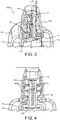
FIG. 3 is a partial perspective, cross-sectional view, not to scale, of the drug delivery device ofFIG. 2 containing a sealing material according to a first embodiment of the disclosure. -
FIG. 4 is a partial cross-sectional view, not to scale, of the sealing material in the fluid outlet nozzle of the device ofFIG. 3 . -
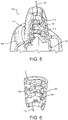
FIG. 5 is a view, not to scale, of the device ofFIG. 3 with a fluid jet ejection cartridge removed therefrom. -
FIG. 6 is a partial view, not to scale, of the sealing material according to the first embodiment of the disclosure. -
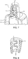
FIG. 7 is a partial perspective, cross-sectional view, not to scale, of the drug delivery device ofFIG. 2 containing a sealing material according to a second embodiment of the disclosure. -
FIG. 8 is a partial view, not to scale, of the sealing material according to the second embodiment of the disclosure. -
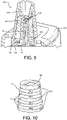
FIG. 9 is a partial perspective, cross-sectional view, not to scale, of the drug delivery device ofFIG. 2 containing a sealing material according to a third embodiment of the disclosure. -
FIG. 10 is a perspective view, not to scale, of the sealing material according to the third embodiment of the disclosure. -
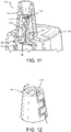
FIG. 11 is a partial perspective, cross-sectional view, not to scale, of the drug delivery device ofFIG. 2 containing a sealing material according to a fourth embodiment of the disclosure. -
FIG. 12 is a perspective view, not to scale, of the sealing material according to the fourth embodiment of the disclosure. - An illustration of a pharmaceutical
drug delivery device 100 is illustrated inFIG. 2 . The pharmaceuticaldrug delivery device 100 includes a drugdelivery device body 102, having afluid outlet nozzle 104 attached to the drugdelivery device body 102. Apower button 106 is provided to activate the drug delivery device as indicated by anLED 108. During use of the pharmaceuticaldrug delivery device 100, a dispensebutton 110 is pressed and fluid delivery is indicated by LED's 112. When not in use, aplug 114 may be inserted into thedevice 100 to prevent fluid from drying out on a fluid jet ejection head used to deliver the pharmaceutical drug to a user. The drugdelivery device body 102 also contains a power source and a controller for controlling the ejection of fluid from the fluid jet ejection head. - With reference to
FIG. 3 , a cross-sectional, perspective view of a portion of the pharmaceuticaldrug delivery device 100 is illustrated. The pharmaceuticaldrug delivery device 100 includes the drugdelivery device body 102 for holding a fluidjet ejection cartridge 116 containing apharmaceutical fluid 118 in acartridge holder 120. Afluid filter 122 is disposed in the fluidjet ejection cartridge 116 to filter the fluid flowing throughfilter tower structures 124 to a fluidjet ejection head 126. In some embodiments, the fluidjet ejection cartridge 116 may also contain a backpressure control device such as a bladder or foam for inducing a backpressure on the fluidjet ejection head 126. The fluidjet ejection head 126 may be selected from any of the conventional types of fluid jet ejection heads, including but not limited to, thermal jet ejection heads, bubble jet ejection heads, piezoelectric jet ejection heads, and the like. Each of the foregoing ejection heads can produce a spray of fluid on demand. - As set forth above, when the
fluid outlet nozzle 104 is inserted into thenostril 30 of a user, and the user inhales, a low pressure area is formed adjacent to an exposedsurface 128 of the fluidjet ejection head 126. This low pressure area creates a "pressure differential" between the exposedsurface 128 of the fluidjet ejection head 126 and the fluid in the fluidjet ejection cartridge 116. The pressure differential can cause unwanted flow or drooling of fluid from the fluidjet ejection head 126. Accordingly, in order to reduce the pressure differential adjacent to the exposedsurface 128 of the fluidjet ejection head 126, a sealingmaterial 130 containing a serpentineair flow path 132, is provided in thefluid outlet nozzle 104 surrounding the fluidjet ejection cartridge 116. In one embodiment, the sealingmaterial 130 contains alternatingnotches 134 that are in fluid flow communication with adjacent air chambers 136 so that a serpentine path through the sealingmaterial 130 is provided. - The sealing material for use with the pharmaceutical
drug delivery device 100 may be selected from a wide variety of sulfur-free resilient materials such as natural or synthetic rubber, and thermoplastic or thermoset elastomers having a shore A durometer of less than about 60 that are compatible with the fluids being ejected from the fluidjet ejection head 126. Examples of such materials include, but are not limited to natural rubber, EPDM rubber, and a dynamically vulcanized alloy consisting mostly of fully cured EPDM rubber particles encapsulated in a polypropylene (PP) matrix, available from ExxonMobil under the tradename SANTOPRENE. The sealingmaterial 130 can be molded and shaped to provide the serpentineair flow path 132 therein and can provide a seal between the fluidjet ejection cartridge 116 and thefluid outlet nozzle 104. It will be appreciated that the drugdelivery device body 102 of the pharmaceuticaldrug delivery device 100 is not air-tight and thus provides inlet air flows from a variety of locations such as from thebuttons jet ejection cartridge 116 into the drugdelivery device body 102. - When the
fluid outlet nozzle 104 is capped with aplug 114 as shown inFIG. 4 , the chambers 136 provide areas for holding humid air so that any fluid on the exposedsurface 128 of the fluidjet ejection head 126 is less likely to dry out between uses of the pharmaceuticaldrug delivery device 100. Thus chambers 136 provide humidification zones in thefluid outlet nozzle 104 of the pharmaceuticaldrug delivery device 100 when capped. -
FIGs. 5 and 6 provide more details of the sealingmaterial 130 andair flow path 132 through the sealingmaterial 130. In the embodiment ofFIGs. 3-6 , the sealingmaterial 130 contains a plurality ofseparators 140 that divide the sealing material into thechambers 136A-C illustrated inFIG. 6 . Each of theseparators 140 has anotch 142 therein, wherein thenotches 142 inadjacent separators 140 are on opposite sides of the fluidjet ejection cartridge 116 thereby providing the serpentineair flow path 132 around the fluidjet ejection cartridge 116. In the embodiments illustrated inFIGs. 3-6 , the sealingmaterial 130 contains at least threeseparators 140 providing threechambers 136A-C. - In other embodiments, illustrated in
FIGs. 7-8 and11-12 , the sealing material contains a serpentine air flow path that devoid of the air chambers and notches and is selected to have a much greater length than the cross-sectional air flow area of the flow path. In some embodiments, the serpentine air flow path has a length to area ratio ranging from about 30 : 1 to about 100 : 1, such as from about 35 :1 to about 60 : 1. - An alternative configuration of a sealing
material 150 for the pharmaceuticaldrug delivery device 100 is illustrated inFIGs. 7 and 8 . According to this embodiment, the sealingmaterial 150 contains one or more serpentineair flow paths 152 adjacent to the fluidjet ejection cartridge 116 rather than theseparators 140 and chambers 136 described above. At least two serpentineair flow paths 152 are provided in sealingmaterial 150, and the two serpentineair flow paths 152 are on opposite sides of the fluidjet ejection cartridge 116. In order to provide a sufficient humidification zone, when the pharmaceuticaldrug delivery device 100 is capped, the sealingmaterial 150 may contain three or four serpentineair flow paths 152 around the inside circumference thereof. - In other embodiments, the elongate serpentine air flow paths may be positioned on an exterior surface of the sealing material rather than on an inside surface adjacent to the fluid
jet ejection cartridge 116.FIGs. 9-12 illustrate alternative embodiments for sealingmaterials FIGs. 9 and 10 , the sealingmaterial 160 includes separator rings 162 having alternatingnotches 164 therein to providechambers 166A-166D between the separator rings 162. Accordingly, thenotches 164 may be on opposite sides of the sealingmaterial 160 in order to provide a serpentine path for air flow in thefluid outlet nozzle 104 between anexterior surface 166 of the sealingmaterial 160 and aninterior surface 168 of thefluid outlet nozzle 104. - In
FIGs. 11 and 12 , the sealingmaterial 170 includesserpentine paths 172 on opposing sides of the sealingmaterial 170. As with the previous embodiment, theserpentine paths 172 are disposed between aninside surface 168 of thefluid outlet nozzle 104 and anoutside surface 174 of the sealingmaterial 170. Twoserpentine paths 172 are illustrated inFIG. 12 , however, the sealingmaterial 170 may contain up to fourserpentine paths 172 around a circumference of the sealingmaterial 170. With all of the embodiments described above, when theplug 114 is used to cap the pharmaceuticaldrug delivery device 100, the serpentine paths and chamber provide a humidification zone between thefluid outlet nozzle 104 and the fluidjet ejection cartridge 116 in order to prevent the fluidjet ejection head 126 from drying out between uses. - In the embodiments, illustrated in
FIGs. 7-8 and11-12 , the sealingmaterials air flow paths - It is noted that, as used in this specification and the appended claims, the singular forms "a," "an," and "the," include plural referents unless expressly and unequivocally limited to one referent. As used herein, the term "include" and its grammatical variants are intended to be nonlimiting, such that recitation of items in a list is not to the exclusion of other like items that can be substituted or added to the listed items.
- For the purposes of this specification and appended claims, unless otherwise indicated, all numbers expressing quantities, percentages or proportions, and other numerical values used in the specification and claims, are to be understood as being modified in all instances by the term "about." Accordingly, unless indicated to the contrary, the numerical parameters set forth in the following specification and attached claims are approximations that can vary depending upon the desired properties sought to be obtained by the present disclosure. At the very least, and not as an attempt to limit the application of the doctrine of equivalents to the scope of the claims, each numerical parameter should at least be construed in light of the number of reported significant digits and by applying ordinary rounding techniques.
- While particular embodiments have been described, alternatives, modifications, variations, improvements, and substantial equivalents that are or can be presently unforeseen can arise to applicants or others skilled in the art. Accordingly, the appended claims as filed and as they can be amended are intended to embrace all such alternatives, modifications variations, improvements, and substantial equivalents.
Claims (16)
- A pharmaceutical drug delivery device (100), characterized in that comprising:a drug delivery device body (102);a fluid outlet nozzle (104) attached to the drug delivery device body (102);a fluid jet ejection cartridge (116) containing a liquid pharmaceutical drug (118) is disposed in the drug delivery device body (102), wherein a fluid jet ejection head (126) is attached to the fluid jet ejection cartridge (116) and the fluid jet ejection head (126) is in fluid flow communication with the fluid outlet nozzle (104); andan elongate, serpentine air flow path (132, 152, 172), between an outer surface of the fluid jet ejection cartridge (116) and an inner surface of the fluid outlet nozzle (104), wherein the elongate, serpentine air flow path (132, 152, 172) provides a reduced pressure differential adjacent to a surface of the fluid jet ejection head (126) upon use of the pharmaceutical drug delivery device (100) and provides a humidification zone.
- The pharmaceutical drug delivery device (100) of claim 1, wherein
The elongate, serpentine air flow path (132, 152, 172) has a length to cross-sectional area ratio of about 30 : 1 to about 100 : 1. - The pharmaceutical drug delivery device (100) of claim 1, whereinthe elongate, serpentine air flow path (132) is provided by a multi-chamber sealing material (130) disposed in the fluid outlet nozzle (104) between an interior surface of the fluid outlet nozzle (104) and an exterior surface of the fluid jet ejection cartridge (116),wherein the multi-chamber sealing material (130) comprises air chambers (136, 136A, 136B, 136C) and notches (134, 142) for air flow between adjacent air chambers (136, 136A, 136B, 136C).
- The pharmaceutical drug delivery device (100) of claim 3, wherein
the elongate, serpentine air flow path (132) is provided between an exterior surface of the fluid jet ejection cartridge (116) and an interior surface of the multi-chamber sealing material (130) through the notches (134, 142) and the air chambers (136, 136A, 136B, 136C) of the multi-chamber sealing material (130). - The pharmaceutical drug delivery device (100) of claim 1, wherein
the elongate, serpentine air flow path (172) is provided between the interior surface (168) of the fluid outlet nozzle (104) and an exterior surface (166, 174) of a sealing material (160, 170) disposed in the fluid outlet nozzle (104) adjacent to the fluid jet ejection cartridge (116). - The pharmaceutical drug delivery device (100) of claim 1, further comprising:
a plug (114) to cap off the fluid outlet nozzle (104) and create the humidification zone in the pharmaceutical drug delivery device (100) between uses. - A method for reducing a pressure differential on a fluid jet ejection head (126) for a nasal spray device, the method being characterized in that comprising:providing a pharmaceutical drug delivery device (100) having: a fluid outlet nozzle (104) attached to a drug delivery device body (102); a fluid jet ejection cartridge (116) disposed in the drug delivery device body (102), the fluid jet ejection cartridge (116) containing the fluid jet ejection head (126) in fluid flow communication with the fluid outlet nozzle (104) and a pharmaceutical drug in the fluid jet ejection cartridge (116);inserting a sealing material (130, 150, 160, 170) between an outer surface of the fluid jet ejection cartridge (116) and an inner surface of the fluid outlet nozzle (104), wherein the sealing material (130, 150, 160, 170) contains an elongate, serpentine air flow path (132, 152, 172) therein to provide a reduced pressure differential adjacent to a surface of the fluid jet ejection head (126) upon use of the pharmaceutical drug delivery device (100); andactivating the nasal spray device while flowing air through the drug delivery device body (102) and the elongate, serpentine air flow path (132, 152, 172) when the fluid outlet nozzle (104) is inserted into a nasal passage of a user thereby preventing fluid from drooling from the fluid jet ejection head (126).
- The method of claim 7, wherein
the elongate, serpentine air flow path (132, 152, 172) has a length to cross-sectional area ratio of about 30 : 1 to about 100 : 1. - The method of claim 7, wherein
the reduced pressure differential is provided by a multi-chamber sealing material (130) disposed in the fluid outlet nozzle (104), wherein the multi-chamber sealing material (130) comprises air chambers (136, 136A, 136B, 136C) and notches (134, 142) for air flow between adjacent air chambers (136, 136A, 136B, 136C). - The method of claim 9, wherein
the reduced pressure differential is provided between the outer surface of the fluid jet ejection cartridge (116) and the air chambers (136, 136A, 136B, 136C) of the multi-chamber sealing material (130). - The method of claim 7, wherein
the reduced pressure differential is provided between the inner surface of the fluid outlet nozzle (104) and an exterior surface of the sealing material (160, 170). - A method for preventing a surface of a fluid jet ejection head (126) for a nasal spray device from drying out between uses, the method being characterized in that comprising:providing a pharmaceutical drug delivery device (100) having: a fluid outlet nozzle (104) attached to a drug delivery device body (102); a fluid jet ejection cartridge (116) disposed in the drug delivery device body (102), the fluid jet ejection cartridge (116) containing the fluid jet ejection head (126) in fluid flow communication with the fluid outlet nozzle (104) and a pharmaceutical drug in the fluid jet ejection cartridge (116);inserting a sealing material (130, 150, 160, 170) between an outer surface of the fluid jet ejection cartridge (116) and an inner surface of the fluid outlet nozzle (104), wherein the sealing material (130, 150, 160, 170) contains an elongate, serpentine air flow path (132, 152, 172) therein to provide a humidification zone in the pharmaceutical drug delivery device (100) adjacent to a surface (128) of the fluid jet ejection head (126) between uses of the pharmaceutical drug delivery device (100); andplugging the fluid outlet nozzle (104) with a cap (114) to prevent drying out of the surface (128) of the fluid jet ejection head (126).
- The method of claim 12, wherein
the elongate, serpentine air flow path (132, 152, 172) has a length to cross-sectional area ratio of about 30 : 1 to about 100 : 1. - The method of claim 12, wherein
the humidification zone is provided by a multi-chamber sealing material (130) disposed in the fluid outlet nozzle (104), wherein the multi-chamber sealing material (130) comprises air chambers (136, 136A, 136B, 136C) and notches (134, 142) for air flow between adjacent air chambers (136, 136A, 136B, 136C). - The method of claim 14, wherein
the humidification zone is provided between the outer surface of the fluid jet ejection cartridge (116) and the air chambers (136, 136A, 136B, 136C) of the multi-chamber sealing material (130). - The method of claim 12, wherein
the humidification zone is provided between the inner surface of the fluid outlet nozzle (104) and an exterior surface of the sealing material (160, 170).
Applications Claiming Priority (1)
| Application Number | Priority Date | Filing Date | Title |
|---|---|---|---|
| US17/205,280 US11925749B2 (en) | 2021-03-18 | 2021-03-18 | Venting of pharmaceutical drug delivery device for air flow and humidity control |
Publications (1)
| Publication Number | Publication Date |
|---|---|
| EP4059551A1 true EP4059551A1 (en) | 2022-09-21 |
Family
ID=80683988
Family Applications (1)
| Application Number | Title | Priority Date | Filing Date |
|---|---|---|---|
| EP22160661.9A Withdrawn EP4059551A1 (en) | 2021-03-18 | 2022-03-08 | Pharmaceutical drug delivery device, and method of air flow and humidity control thereof |
Country Status (4)
| Country | Link |
|---|---|
| US (1) | US11925749B2 (en) |
| EP (1) | EP4059551A1 (en) |
| JP (1) | JP2022145587A (en) |
| CN (1) | CN115105693B (en) |
Citations (7)
| Publication number | Priority date | Publication date | Assignee | Title |
|---|---|---|---|---|
| WO1997003711A2 (en) * | 1995-07-14 | 1997-02-06 | Techbase Pty. Ltd. | Spacer for aerosol medication |
| WO1998041256A2 (en) * | 1997-03-14 | 1998-09-24 | Astra Aktiebolag (Publ) | Inhalation device |
| WO1999020331A1 (en) * | 1997-10-17 | 1999-04-29 | Systemic Pulmonary Development, Ltd. | Method and apparatus for delivering aerosolized medication |
| WO2005097242A2 (en) * | 2004-03-30 | 2005-10-20 | Sunil Kumar Dhuper | Aerosol inhalation systems and interface elements for use therein |
| WO2006061637A2 (en) * | 2004-12-09 | 2006-06-15 | Cambridge Consultants Limited | Dry powder inhalers |
| WO2008040062A1 (en) * | 2006-10-05 | 2008-04-10 | Medi-Stream Pty Ltd | Medication holder |
| WO2015086276A1 (en) * | 2013-12-09 | 2015-06-18 | Pharmachemie B.V. | Dry powder inhaler |
Family Cites Families (23)
| Publication number | Priority date | Publication date | Assignee | Title |
|---|---|---|---|---|
| JPH1033677A (en) * | 1996-07-24 | 1998-02-10 | Unisia Jecs Corp | Nasal administration device |
| SE9700937D0 (en) * | 1997-03-14 | 1997-03-14 | Astra Ab | Powder inhales I |
| ES2226721T3 (en) * | 2000-06-13 | 2005-04-01 | Andi-Ventis Limited | ORAL PIECE FOR PARTICLE INHALER. |
| AU2003249623A1 (en) | 2002-05-09 | 2003-12-12 | Kurve Technology, Inc. | Particle dispersion chamber for nasal nebulizer |
| CN100569310C (en) * | 2004-08-02 | 2009-12-16 | 佳能株式会社 | Inhalation device |
| GB0515592D0 (en) * | 2005-07-28 | 2005-09-07 | Glaxo Group Ltd | Nozzle for a nasal inhaler |
| DE102006006183A1 (en) * | 2006-02-10 | 2007-08-16 | Pari GmbH Spezialisten für effektive Inhalation | Inhalation therapy device for use in premature babies and toddlers |
| WO2008023014A1 (en) * | 2006-08-22 | 2008-02-28 | Glaxo Group Limited | Actuator for an inhaler |
| GB0623731D0 (en) * | 2006-11-28 | 2007-01-10 | Optinose As | Delivery device |
| WO2008086413A2 (en) | 2007-01-09 | 2008-07-17 | Mystic Pharmaceuticals, Inc. | Intranasal cartridge devices |
| FR2916429B1 (en) * | 2007-05-22 | 2012-10-05 | Valois Sas | PROTECTIVE COVER FOR FLUID PRODUCT DISPENSING HEAD. |
| US9492625B2 (en) * | 2009-11-12 | 2016-11-15 | Stc.Unm | Dry powder inhaler with flutter dispersion member |
| TWM450387U (en) * | 2012-08-31 | 2013-04-11 | Microbase Technology Corp | Replaceable atomization device with negative pressure structure |
| JP6249832B2 (en) * | 2014-03-13 | 2017-12-20 | 株式会社エー・アンド・デイ | Inhaler nozzle |
| CN104771817B (en) * | 2015-03-25 | 2018-06-15 | 西安交通大学医学院第一附属医院 | Medical atomizer |
| US20160302972A1 (en) * | 2015-04-15 | 2016-10-20 | Exercore LLC | Nasal Air Flow Device |
| JP6879571B6 (en) | 2015-08-28 | 2021-06-30 | リージェンツ オブ ザ ユニバーシティ オブ ミネソタ | Nozzles and methods for mixing fluid flows |
| US9636430B2 (en) | 2015-09-16 | 2017-05-02 | The Procter & Gamble Company | Microfluidic delivery system and cartridge having an outer cover |
| AU2016380926B2 (en) * | 2015-12-28 | 2021-12-23 | Koninklijke Philips N.V. | Air-flow in a nebulizer head |
| CN205569475U (en) * | 2016-02-26 | 2016-09-14 | 白雪波 | Convenient and practical's department of anesthesia uses face guard |
| US20170266396A1 (en) * | 2016-03-21 | 2017-09-21 | Joseph Feldman | Nasal spray apparatus |
| US12496413B2 (en) * | 2018-02-19 | 2025-12-16 | Philip Morris Products S.A. | Dry powder inhaler |
| CN212491195U (en) | 2020-01-15 | 2021-02-09 | 诺斯欧博森公司 | Nasal obstruction |
-
2021
- 2021-03-18 US US17/205,280 patent/US11925749B2/en active Active
-
2022
- 2022-02-24 CN CN202210174791.4A patent/CN115105693B/en active Active
- 2022-03-08 EP EP22160661.9A patent/EP4059551A1/en not_active Withdrawn
- 2022-03-10 JP JP2022036765A patent/JP2022145587A/en active Pending
Patent Citations (7)
| Publication number | Priority date | Publication date | Assignee | Title |
|---|---|---|---|---|
| WO1997003711A2 (en) * | 1995-07-14 | 1997-02-06 | Techbase Pty. Ltd. | Spacer for aerosol medication |
| WO1998041256A2 (en) * | 1997-03-14 | 1998-09-24 | Astra Aktiebolag (Publ) | Inhalation device |
| WO1999020331A1 (en) * | 1997-10-17 | 1999-04-29 | Systemic Pulmonary Development, Ltd. | Method and apparatus for delivering aerosolized medication |
| WO2005097242A2 (en) * | 2004-03-30 | 2005-10-20 | Sunil Kumar Dhuper | Aerosol inhalation systems and interface elements for use therein |
| WO2006061637A2 (en) * | 2004-12-09 | 2006-06-15 | Cambridge Consultants Limited | Dry powder inhalers |
| WO2008040062A1 (en) * | 2006-10-05 | 2008-04-10 | Medi-Stream Pty Ltd | Medication holder |
| WO2015086276A1 (en) * | 2013-12-09 | 2015-06-18 | Pharmachemie B.V. | Dry powder inhaler |
Also Published As
| Publication number | Publication date |
|---|---|
| CN115105693A (en) | 2022-09-27 |
| US20220296828A1 (en) | 2022-09-22 |
| US11925749B2 (en) | 2024-03-12 |
| CN115105693B (en) | 2024-07-16 |
| JP2022145587A (en) | 2022-10-04 |
Similar Documents
| Publication | Publication Date | Title |
|---|---|---|
| US10124129B2 (en) | Dispensing device, storage device and method for dispensing a formulation | |
| EP0855224B1 (en) | Atomizer | |
| JP4411901B2 (en) | Atomizer | |
| CN109172961B (en) | Sprayer device | |
| EP0880373B1 (en) | Nebulizer apparatus | |
| ES2280386T3 (en) | INHALER WITH EXTRAIBLE GOTICULAS EXPULSION CARTRIDGE. | |
| US8925544B2 (en) | Portable nebulizer device | |
| US9440020B2 (en) | Nasal irrigator | |
| CN100569310C (en) | Inhalation device | |
| ES2699988T3 (en) | Nebulizer for babies and patients with respiratory problems | |
| US20110137290A1 (en) | Method and Device for Nasal Irrigation and drug delivery | |
| JP2006212203A (en) | Inhalation device and liquid agent discharge cartridge | |
| KR20080036111A (en) | Self Sealing T Parts and Valve Type T Parts | |
| US20120000460A1 (en) | Method and Device for Nasal Drug Delivery and Nasal Irrigation | |
| US20140283820A1 (en) | Method for Esophageal Drug Delivery | |
| CN119633213B (en) | Atomizing assembly, container assembly and nasal spray device | |
| US20220296829A1 (en) | Nose cone vent design for inhalation device | |
| US11925749B2 (en) | Venting of pharmaceutical drug delivery device for air flow and humidity control | |
| US20240189522A1 (en) | Venting of pharmaceutical drug delivery device for air flow and humidity control | |
| CN101472634A (en) | Inhaler flow channel | |
| EP4039297A1 (en) | Drug delivery device, method of controlling fluid plume and method of nasal cavity injection | |
| WO2013126650A1 (en) | Nasal nebulizer for transporting and storing fluids | |
| WO2005037557A1 (en) | Liquid jetting head | |
| EP4039299A1 (en) | Drug delivery device, method of controlling fluid plume and method of nasal cavity injection | |
| CN101998871A (en) | Spray head cartridge and inhalation device to which the spray head cartridge can be attached |
Legal Events
| Date | Code | Title | Description |
|---|---|---|---|
| PUAI | Public reference made under article 153(3) epc to a published international application that has entered the european phase |
Free format text: ORIGINAL CODE: 0009012 |
|
| STAA | Information on the status of an ep patent application or granted ep patent |
Free format text: STATUS: THE APPLICATION HAS BEEN PUBLISHED |
|
| AK | Designated contracting states |
Kind code of ref document: A1 Designated state(s): AL AT BE BG CH CY CZ DE DK EE ES FI FR GB GR HR HU IE IS IT LI LT LU LV MC MK MT NL NO PL PT RO RS SE SI SK SM TR |
|
| STAA | Information on the status of an ep patent application or granted ep patent |
Free format text: STATUS: REQUEST FOR EXAMINATION WAS MADE |
|
| 17P | Request for examination filed |
Effective date: 20221110 |
|
| RBV | Designated contracting states (corrected) |
Designated state(s): AL AT BE BG CH CY CZ DE DK EE ES FI FR GB GR HR HU IE IS IT LI LT LU LV MC MK MT NL NO PL PT RO RS SE SI SK SM TR |
|
| GRAP | Despatch of communication of intention to grant a patent |
Free format text: ORIGINAL CODE: EPIDOSNIGR1 |
|
| STAA | Information on the status of an ep patent application or granted ep patent |
Free format text: STATUS: GRANT OF PATENT IS INTENDED |
|
| INTG | Intention to grant announced |
Effective date: 20240917 |
|
| STAA | Information on the status of an ep patent application or granted ep patent |
Free format text: STATUS: THE APPLICATION IS DEEMED TO BE WITHDRAWN |
|
| 18D | Application deemed to be withdrawn |
Effective date: 20250118 |
|
| 19U | Interruption of proceedings before grant |
Effective date: 20241024 |