EP4059410A1 - Arrangement and method for measuring an electrical property of a body - Google Patents
Arrangement and method for measuring an electrical property of a body Download PDFInfo
- Publication number
- EP4059410A1 EP4059410A1 EP21163148.6A EP21163148A EP4059410A1 EP 4059410 A1 EP4059410 A1 EP 4059410A1 EP 21163148 A EP21163148 A EP 21163148A EP 4059410 A1 EP4059410 A1 EP 4059410A1
- Authority
- EP
- European Patent Office
- Prior art keywords
- contact
- electrodes
- contacts
- electrode
- resistance
- Prior art date
- Legal status (The legal status is an assumption and is not a legal conclusion. Google has not performed a legal analysis and makes no representation as to the accuracy of the status listed.)
- Granted
Links
Images


Classifications
-
- A—HUMAN NECESSITIES
- A61—MEDICAL OR VETERINARY SCIENCE; HYGIENE
- A61B—DIAGNOSIS; SURGERY; IDENTIFICATION
- A61B5/00—Measuring for diagnostic purposes; Identification of persons
- A61B5/05—Detecting, measuring or recording for diagnosis by means of electric currents or magnetic fields; Measuring using microwaves or radio waves
- A61B5/053—Measuring electrical impedance or conductance of a portion of the body
- A61B5/0531—Measuring skin impedance
-
- A—HUMAN NECESSITIES
- A61—MEDICAL OR VETERINARY SCIENCE; HYGIENE
- A61B—DIAGNOSIS; SURGERY; IDENTIFICATION
- A61B5/00—Measuring for diagnostic purposes; Identification of persons
- A61B5/05—Detecting, measuring or recording for diagnosis by means of electric currents or magnetic fields; Measuring using microwaves or radio waves
- A61B5/053—Measuring electrical impedance or conductance of a portion of the body
- A61B5/0537—Measuring body composition by impedance, e.g. tissue hydration or fat content
-
- A—HUMAN NECESSITIES
- A61—MEDICAL OR VETERINARY SCIENCE; HYGIENE
- A61B—DIAGNOSIS; SURGERY; IDENTIFICATION
- A61B5/00—Measuring for diagnostic purposes; Identification of persons
- A61B5/68—Arrangements of detecting, measuring or recording means, e.g. sensors, in relation to patient
- A61B5/6801—Arrangements of detecting, measuring or recording means, e.g. sensors, in relation to patient specially adapted to be attached to or worn on the body surface
- A61B5/6813—Specially adapted to be attached to a specific body part
- A61B5/6814—Head
- A61B5/6815—Ear
- A61B5/6817—Ear canal
-
- H—ELECTRICITY
- H04—ELECTRIC COMMUNICATION TECHNIQUE
- H04R—LOUDSPEAKERS, MICROPHONES, GRAMOPHONE PICK-UPS OR LIKE ACOUSTIC ELECTROMECHANICAL TRANSDUCERS; ELECTRIC HEARING AIDS; PUBLIC ADDRESS SYSTEMS
- H04R5/00—Stereophonic arrangements
- H04R5/033—Headphones for stereophonic communication
Definitions
- the object is achieved by an arrangement for measuring an electrical property of a human or animal body according to claim 1 and by a method for measuring an electrical property of a human or animal body according to claim 10.
- the contact resistance of the first electrode may be indicative of a resistance between the body and the first electrode.
- the contact resistance of the second electrode may be indicative of a resistance between the body and the second electrode.
- each contact is arranged on a respective shell of a hearing device, the shell configured to be placed within an ear canal of a user, wherein the electrodes are arranged on an outside of the shell so as to be in contact with ear canal tissue.
- a second switch s arranged to selectively connect the other one of the electrodes with a second terminal of the measurement unit.
- the measurement is repeated multiple times to monitor the electrical property of the body over time.
- the first switches and the third switches are closed and the second switch associated with one of the contacts is closed while the second switch associated with the other one of the contacts is open, wherein an impedance and/or resistance between the two contacts is determined as an impedance and/or resistance measured by the measurement unit minus parallel total contact resistances of both contacts.
- a direct voltage is applied between the electrodes 3.1, 3.2 and a resulting direct current DC between the electrodes 3.1, 3.2 can be measured. It is also possible to apply an alternating voltage between the electrodes 3.1, 3.2 and measure a resulting alternating current AC running through the ear canal tissue 2 between the electrodes 3.1, 3.2.
- a contact resistance can for example be determined from the DC-measurement.
- the AC-measurement may be used as an indicator for water content in the underlying tissue. Since water has a high relative dielectric constant the amount of water in a tissue has a strong impact on the AC-measurement. From the DC and AC measurements an impedance of the skin and the underlying tissue can be determined.
- the impedance is a complex value specifying the relation between the amplitudes of voltage and current of a sine wave signal with a frequency passing through an element.
- the said measurement can be performed in the left ear and in the right ear. Data obtained from both ears may be correlated, e.g. using a wireless connection, for example at 2.4 GHz, in order to provide a more accurate calculation. If, for example, the measurement of the contact resistance on the first ear differs by more than a predefined factor from the contact resistance of the contact of the second ear this may indicate, that the measurement conditions are not optimal for conducting a measurement of the head impedance.
- the predefined factor may be in the range of 1.1 to 5. In a preferred embodiment the predefined factor is in a range of 1.5 to 2. It should be pointed out that the contact resistance may be a real value specified in Ohm. It is also possible to determine a contact impedance, when an alternating current is applied to the contacts. In this case it is possible to specify the contact impedance as a complex value.
- the measurement may comprise determining the contact resistance between a respective pair of electrodes 3.1, 3.2 in both ears and determining the interaural impedance between the left ear and the right ear.
- the skin conductivity, the impedance between contacts in an ear canal, and the head or body impedance measurement may be used to assess:
Landscapes
- Health & Medical Sciences (AREA)
- Life Sciences & Earth Sciences (AREA)
- Medical Informatics (AREA)
- Molecular Biology (AREA)
- Veterinary Medicine (AREA)
- Biophysics (AREA)
- Pathology (AREA)
- Engineering & Computer Science (AREA)
- Biomedical Technology (AREA)
- Heart & Thoracic Surgery (AREA)
- Public Health (AREA)
- Physics & Mathematics (AREA)
- Surgery (AREA)
- Animal Behavior & Ethology (AREA)
- General Health & Medical Sciences (AREA)
- Nuclear Medicine, Radiotherapy & Molecular Imaging (AREA)
- Radiology & Medical Imaging (AREA)
- Otolaryngology (AREA)
- Dermatology (AREA)
- Measurement And Recording Of Electrical Phenomena And Electrical Characteristics Of The Living Body (AREA)
Abstract
Description
- The invention relates to an arrangement and a method for measuring an electrical property of a human or animal body.
-
US 2017/0078785 A1 discloses earbuds configured with one or more biometric sensors. At least one of the biometric sensors is configured to be pressed up against a portion of the tragus for making biometric measurements. In some embodiments, the housing of the earbud can be symmetric so that the earbud can be worn interchangeably in either a left or a right ear of a user. In such an embodiment, the earbud can include a sensor and circuitry configured to determine and alter operation of the earbud in accordance to which ear the earbud is determined to be positioned within. - It is an object of the present invention to provide an improved arrangement and an improved method for measuring an electrical property of a human or animal body.
- The object is achieved by an arrangement for measuring an electrical property of a human or animal body according to claim 1 and by a method for measuring an electrical property of a human or animal body according to
claim 10. - Preferred embodiments of the invention are given in the dependent claims.
- According to the invention an arrangement for measuring an electrical property of a human or animal body between a first position and a second position of the body is proposed, the arrangement comprising a first contact configured to contact the body at the first position and a second contact configured to contact the body at the second position, each contact comprising at least a first and a second electrode for contacting the body, the arrangement further comprising at least two measurement units configured to measure a resistance and/or impedance between the contacts and to measure a contact resistance of the first and/or second electrode.
- The measurement units may comprise a first and a second terminal. The second terminal may be regarded as a ground of the measurement unit.
- The arrangement further comprises a galvanic connection, e.g. a cable, wherein the galvanic connection is adapted to interconnect the measurement units. The cable may be used as a common ground of the measurement units facilitating measurement of a resistance and/or impedance between the first contact and the second contact. The galvanic connection may be arranged within a hearing device, e.g. for the case that both contacts are arranged on a surface of a shell of the hearing device. Likewise, the galvanic connection may be a cable adapted to connect two hearing devices.
- The contact resistance of the first electrode may be indicative of a resistance between the body and the first electrode. The contact resistance of the second electrode may be indicative of a resistance between the body and the second electrode.
- The contact resistance may be a transition resistance which leads to a voltage drop, when a current passes from the electrode to a tissue of the body at the position where the electrode touches the body, in particular to a skin of the body.
- It may depend on multiple factors, for example the area of the electrodes and/or the force which is applied to press the contact against the skin. The contact resistance may also depend on the presence of sweat, cerumen or any other substance at the surface of the skin. The contact resistance may further depend on the material of the electrodes, on dirt, corrosion or an oxide formed at the surface of the electrode and on the roughness of the surface of the electrodes. The contact resistance needs to be taken into account in order to obtain a precise measurement of the body resistance between the two contacts. The contact resistance may depend also from the electrical configuration of the electrodes. For example both electrodes may be connected in parallel. In this case, the contact resistance may be measured by measuring a resistance between the body and the first and second electrode. In another case, the current may be injected from the first electrode of the contact. In this case, the contact resistance may be measured by measuring a resistance between the body and the first electrode.
- Measuring a resistance may comprise measuring an impedance. Generally, impedance is a complex valued generalization of the resistance.
- In an exemplary embodiment, each contact is arranged on a respective shell of a hearing device, the shell configured to be placed within an ear canal of a user, wherein the electrodes are arranged on an outside of the shell so as to be in contact with ear canal tissue.
- In an exemplary embodiment, the electrodes are respectively formed as an arc.
- In an exemplary embodiment, the electrodes are respectively formed as a fork with two or more prongs, wherein the prongs of one electrode are intertwined with those of the other electrode.
- In an exemplary embodiment, the arrangement may comprise two hearing devices configured to be placed within a left ear canal and a right ear canal of the user, wherein the cable is arranged to interconnect the hearing devices. This allows for measuring the head impedance or resistance. Hearing devices are suitable for doing this measurement as they are arranged in a suitable location within the ear, comprise a processor, are capable of performing electrical measurements, and comprise communication interfaces to submit measurement results, e.g. to a smart phone. As a hearing device also comprises a speaker or receiver, it may easily be configured to acoustically inform the person wearing the hearing devices about the measurement or output a warning. The cable may be releasably connectable or connected to the hearing devices, e.g. by sockets and plugs.
- In an exemplary embodiment, the measurement unit is connected to one of the electrodes with a first terminal, wherein a first switch is arranged to selectively short the two electrodes to connect both electrodes to the first terminal of the measurement unit.
- In an exemplary embodiment, a second switch s arranged to selectively connect the other one of the electrodes with a second terminal of the measurement unit.
- In an exemplary embodiment, a third switch is arranged to selectively connect the second terminal of the measurement unit to the cable. This has the advantage that a measurement of a contact resistance of a contact or an electrode of a contact is not disturbed by an electrical connection to another part of the body.
- In an exemplary embodiment, the contacts are placed on a respective printed circuit board. The printed circuit board may be a flexible printed-circuit board.
- In an exemplary embodiment, the measurement unit for measuring a resistance or an impedance may comprise a current source and a voltmeter and/or a voltage source and an amperemeter. This way, one of voltage and current is known and the other can be determined in order to determine a resistance. The current source or voltage source may be coupled to a power source of the hearing device and/or be supplied with energy from the power source of the hearing device. This allows for doing without an additional current source or voltage source. The voltage of the voltage source should be less than 4 volts. This allows for using Lithium accumulators and prevents subjecting the body to excessively high voltages.
- According to an aspect of the present invention, a method of determining an electrical property of a human or animal body between a first position and a second position of the body using an arrangement as described above is proposed, wherein the first contact is placed to contact the body at the first position and the second contact is placed to contact the body at the second position, wherein a measurement is performed by applying an electrical signal to the contacts and determining a voltage of the electrical signal and a current of the electrical signal flowing through the body between the contacts, wherein a contact resistance is determined for at least one of the electrodes of the first contact or a contact resistance is determined for at least one of the electrodes of the first contact and at least one of the electrodes of the second contact. The electrical signal may be a DC signal or an AC signal. Applying an electrical signal may comprise applying a voltage or injecting a current. In case a (known) voltage is applied, determining comprises measuring the current. If a (known) current is injected, determining comprises measuring the voltage.
- In an exemplary embodiment, the measurement is repeated multiple times to monitor the electrical property of the body over time.
- In an exemplary embodiment, the first switch is open and the second switch is closed to determine a serial total contact resistance between the two electrodes via the body tissue. The body tissue may be understood as the tissue touching the electrodes of a contact at the position of the contact. The body tissue may be a skin of the body.
- In an exemplary embodiment, the first switches and the third switches are closed and the second switch associated with one of the contacts is closed while the second switch associated with the other one of the contacts is open, wherein an impedance and/or resistance between the two contacts is determined as an impedance and/or resistance measured by the measurement unit minus parallel total contact resistances of both contacts.
- The switches may be semiconductor switches.
- In an exemplary embodiment, the contacts are arranged on a respective shell of a hearing device, wherein the shell is placed within an ear canal of a user, wherein the body tissue is an ear canal tissue.
- In an exemplary embodiment, the impedance between the two contacts is used to assess one or more of:
- - - skin elasticity,
- - water content of tissue,
- - blood profusion/circulation/pressure,
- - hydration,
- - heart beat if the contacts are situated near enough to an artery,
- - sweat,
- - whether a hearing device is worn or not,
- - proximity/contact, and
- - stress/depression.
- The geometry of an earpieces or shell for a hearing instrument is typically shaped to match an anatomy of an inner ear channel of a user. Those shells are constantly in contact with the skin when worn by the user. By installing sensors on the shell, valuable information may be retrieved from the skin property of the ear channel without the need of additional external devices. The present invention describes how the skin conductivity and head impedance can be measured and possible applications to apply this information.
- As the present invention allows for determining the contact resistance of each contact, the measurement of the head impedance may be made independent of this contact resistance which may vary depending on whether sweat or cerumen is present.
- Further scope of applicability of the present invention will become apparent from the detailed description given hereinafter. However, it should be understood that the detailed description and specific examples, while indicating preferred embodiments of the invention, are given by way of illustration only, since various changes and modifications within the spirit and scope of the invention will become apparent to those skilled in the art from this detailed description.
- The present invention will become more fully understood from the detailed description given hereinbelow and the accompanying drawings which are given by way of illustration only, and thus, are not limitive of the present invention, and wherein:
- Figure 1
- is a schematic detail view of a body tissue of an ear canal and a shell of a hearing device,
- Figure 2
- is a schematic view of an exemplary embodiment of a pair of electrodes respectively formed as an arc,
- Figure 3
- is a schematic view of an exemplary embodiment of a pair of electrodes respectively formed as forks with intertwined prongs,
- Figure 4
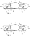
- is a schematic view of a head with two contacts during determination of contact resistances,
- Figure 5
- is a schematic view of a head with two contacts during determination of a head impedance, and
- Figure 6
- is a schematic view of a further embodiment showing a head with two contacts during determination of a head impedance.
- Corresponding parts are marked with the same reference symbols in all figures.
-
Figure 1 is a schematic detail view of a body tissue of an ear canal and a shell 1 of ahearing device 10. The shell 1 is placed into the ear canal and is thus located next to anear canal tissue 2. Acontact 3 is formed by two electrodes 3.1, 3.2 arranged on an outside of the shell 1 so as to be in contact with theear canal tissue 2. - In order to measure the skin conductivity at a certain position of the ear canal for the monaural case, a direct voltage is applied between the electrodes 3.1, 3.2 and a resulting direct current DC between the electrodes 3.1, 3.2 can be measured. It is also possible to apply an alternating voltage between the electrodes 3.1, 3.2 and measure a resulting alternating current AC running through the
ear canal tissue 2 between the electrodes 3.1, 3.2. A contact resistance can for example be determined from the DC-measurement. The AC-measurement may be used as an indicator for water content in the underlying tissue. Since water has a high relative dielectric constant the amount of water in a tissue has a strong impact on the AC-measurement. From the DC and AC measurements an impedance of the skin and the underlying tissue can be determined. The impedance is a complex value specifying the relation between the amplitudes of voltage and current of a sine wave signal with a frequency passing through an element. - The contact resistance depends on multiple factors which may vary over time: humidity, sweat, pressure, cerumen.
- At a point in time t0 the conductivity of the skin at this precise position can thus be identified. By repeating the measurement, changes of the conductivity of the skin over a certain period T of time may be monitored.
- In a binaural case, the said measurement can be performed in the left ear and in the right ear. Data obtained from both ears may be correlated, e.g. using a wireless connection, for example at 2.4 GHz, in order to provide a more accurate calculation. If, for example, the measurement of the contact resistance on the first ear differs by more than a predefined factor from the contact resistance of the contact of the second ear this may indicate, that the measurement conditions are not optimal for conducting a measurement of the head impedance. The predefined factor may be in the range of 1.1 to 5. In a preferred embodiment the predefined factor is in a range of 1.5 to 2. It should be pointed out that the contact resistance may be a real value specified in Ohm. It is also possible to determine a contact impedance, when an alternating current is applied to the contacts. In this case it is possible to specify the contact impedance as a complex value.
- The knowledge of the contact resistance is necessary for precise (interaural) impedance measurements of the head or between any two positions at the body.
-
Figure 2 is a schematic view of an exemplary embodiment of a pair of electrodes 3.1, 3.2 respectively formed as an arc, also referred to as a segment of a circle. -
Figure 3 is a schematic view of an exemplary embodiment of a pair of electrodes 3.1, 3.2 respectively formed as forks with two or more, e.g. three, prongs. The prongs of one electrode 3.1 are intertwined with those of the other electrode 3.2. This allows for averaging of local contact-resistance variations. - In order to measure a head impedance a
cable 4 may be used to provide a galvanic interconnection of thecontacts 3 formed by the electrodes 3.1, 3.2 for the left ear to those of the right ear. - The measurement may comprise determining the contact resistance between a respective pair of electrodes 3.1, 3.2 in both ears and determining the interaural impedance between the left ear and the right ear.
- This measurement principle may also be applied to a measurement within an ear canal, e.g. two
contacts 3 with respectively two electrodes 3.1, 3.2 are applied to different portions of the ear canal. The contact resistance for each pair of electrodes 3.1, 3.2 is determined and then the impedance between the twocontacts 3 is determined. -
Figure 4 is a schematic view of ahead 5 with twocontacts contacts figure 4 the contact resistance is determined between the two electrodes 3.1, 3.2 and 6.1, 6.2 of eachcontact contact cable 4 which may be used to connect the twocontacts figure 4 the third switches 3.6, 6.6 are open so that thecontacts contacts ear canal tissue 2 which is equal to the sum of the individual contact resistance of one of the electrodes 3.1, 6.1 to theear canal tissue 2 and the individual contact resistance of the other one of the electrodes 3.2, 6.2 to theear canal tissue 2 as these individual contact resistances are in series. -
Figure 5 is a schematic view of ahead 5 with twocontacts figure 5 both electrodes 3.1, 3.2 and 6.1, 6.2 of eachcontact contact contacts contacts other contact cable 4 without a third switch 3.6, 6.6. In onecontact 6 the second switch 6.5 is closed thus shorting the measurement unit 6.3 and connecting the electrodes 6.1, 6.2 to thecable 4. In theother contact 3 the second switch 3.5 is open connecting the electrodes 3.1, 3.2 to thecable 4 through the measurement unit 3.3. - Each
contact ear canal tissue 2 with the two individual contact resistances in parallel. Assuming for the sake of simplicity that both individual contact resistances as discussed above with regard tofigure 4 are equal within eachcontact - The head impedance is thus equal to the impedance measured by the measurement unit 3.3 in the setup of
figure 5 minus the parallel total contact resistances of bothcontacts - In particular with the fork-shaped electrodes 3.1, 3.2 as shown in
figure 3 being used for bothcontacts contact
Starting from the setting offigure 5 the first switch 3.4, 6.4 of onecontact contact figure 4 and the said difference allows for determining both individual contact resistances of the electrodes 3.1, 3.2, 6.1, 6.2 for the respective one of thecontacts contact other contact other contact - The determination of the individual contact resistances may be renounced, if the measurement of the head impedance is high in comparison to the contact resistance. This may be the case for example if the head resistance is higher than any of the contact resistances by a factor of 10.
- It should be pointed out, that a measurement unit for measuring a resistance or an impedance may comprise a current source and a voltmeter and/or a voltage source and an amperemeter. A resistance or the impedance can be calculated from the current and voltage values.
-
Figure 6 is a schematic view of a further embodiment. In this example an electrical source 7, which may be part of a measurement unit 3.3, 6.3, provides a voltage U0 and a current I. The current is injected into the first electrode 3.1 of thefirst contact 3. A first voltage U1 is measured at the second electrode 3.2 of thefirst contact 3 by the measurement unit 3.3, e.g. by a voltmeter 3.7 comprised in the measurement unit 3.3. The first electrode 6.1 of thesecond contact 6 is connected to thecable 4 which provides ground. A second voltage U2 is measured at the second electrode 6.2 of thesecond contact 6 by the measurement unit 6.3, e.g. by a voltmeter 6.7 comprised in the measurement unit 6.3. The measuring current of the measurement units 3.3, 6.3 is assumed to be neglectable. It may also be assumed, that the resistance between the first electrode 3.1 and the second electrode 3.2 of thefirst contact 3 is small in comparison to the resistance of the body between thefirst contact 3 and thesecond contact 6. It may also be assumed, that the resistance between the first and the second electrodes 6.1, 6.2 of thesecond contact 6 is small in comparison to the resistance of the body between thefirst contact 3 and thesecond contact 6. - The contact resistance Rc1 for the
first contact 3 is then
- The contact resistance Rc2 for the
second contact 6 is
- The resistance Rbody of the body or
head 5 between thecontacts - From a mechanical point of view, both
contacts hearing device 10. Using a PCB may reduce the cost of production of the arrangement. A flexible PCB may add flexibility in the mechanical arrangement of the contacts. - The skin conductivity, the impedance between contacts in an ear canal, and the head or body impedance measurement may be used to assess:
- skin elasticity
- water content of tissue
- blood profusion/circulation/pressure
- hydration
- heart beat if the
contacts 3 are situated near enough to an artery - sweat
- whether a
hearing device 10 is worn or not - proximity/contact
- stress/depression
- Skin elasticity, blood profusion and/or skin conductivity may be taken into account when modelling shells for hearing devices to improve the comfort of the shell in the ear.
-
- 1
- shell
- 2
- ear canal tissue
- 3
- first contact
- 3.1
- electrode, first electrode
- 3.2
- electrode, second electrode
- 3.3
- measurement unit
- 3.4
- first switch
- 3.5
- second switch
- 3.6
- third switch
- 3.7
- voltmeter
- 4
- cable
- 5
- head
- 6
- second contact
- 6.1
- electrode, first electrode
- 6.2
- electrode, second electrode
- 6.3
- measurement unit
- 6.4
- first switch
- 6.5
- second switch
- 6.6
- third switch
- 6.7
- voltmeter
- 7
- electrical source
- 10
- hearing device
- AC
- alternating current
- DC
- direct current
- U0, U1, U2
- voltage
- I
- current
- Rbody
- resistance
Claims (15)
- An arrangement for measuring an electrical property of a human or animal body between a first position and a second position of the body, the arrangement comprising a first contact (3) configured to contact the body at the first position and a second contact (6) configured to contact the body at the second position, each contact (3, 6) comprising at least a first and a second electrode (3.1, 3.2, 6.1, 6.2) for contacting the body, the arrangement further comprising at least two measurement units (3.3, 6.6) configured to measure a resistance and/or impedance between the contacts (3, 6) and to measure a contact resistance of the first electrode (3.1, 3.2) and/or second electrode (6.1, 6.2), and a galvanic connection adapted to interconnect the measurement units (3.3, 6.3).
- The arrangement of claim 1, wherein each contact (3, 6) is arranged on a respective shell (1) of at least one hearing device (10), the shell (1) configured to be placed within an ear canal of a user, wherein the electrodes (3.1, 3.2, 6.1, 6.2) are arranged on an outside of the shell (1) so as to be in contact with ear canal tissue (2).
- The arrangement of claim 1 or 2, wherein the electrodes (3.1, 3.2, 6.1, 6.2) are respectively formed as an arc.
- The arrangement of claim 1 or 2, wherein the electrodes (3.1, 3.2, 6.1, 6.2) are respectively formed as a fork with two or more prongs, wherein the prongs of one electrode (3.1, 6.1) are intertwined with those of the other electrode (3.2, 6.2).
- The arrangement according to any one of claims 2 to 4, comprising two hearing devices (10) configured to be placed within a left ear canal and a right ear canal of the user, wherein the galvanic connection is configured as a cable (4) arranged to interconnect the hearing devices (10).
- The arrangement according to any one of the preceding claims, wherein the measurement unit (3.3, 6.3) is connected to one of the electrodes (3.1, 6.1) with a first terminal, wherein a first switch (3.4, 6.4) is arranged to selectively short the two electrodes (3.1, 3.2, 6.1, 6.2) to connect both electrodes (3.1, 3.2, 6.1, 6.2) to the first terminal of the measurement unit (3.3, 6.3).
- The arrangement according to claim 6, wherein a second switch (3.5, 6.5) is arranged to selectively connect the other one of the electrodes (3.2, 6.2) with a second terminal of the measurement unit (3.3, 6.3).
- The arrangement according to claim 7, wherein a third switch (3.6, 6.6) is arranged to connect or disconnect the second terminal of the measurement unit (3.3, 6.3) to the cable (4).
- The arrangement according to any one of claims 1 to 8, wherein the first measurement unit (3.3) comprises an electrical source (7) and a voltmeter (3.7), and the second measurement unit (6.3) comprises a voltmeter (6.7), wherein the electrical source (7) is connected to the cable (4) and to the first electrode (3.1) of the first contact (3), and the second electrode (3.2) of the first contact (3) is connected to the voltmeter (3.7) of the first measurement unit (3.3), and the cable (4) is connected to the first electrode (6.1) of the second contact (6), and the voltmeter (6.7) of the second measurement (6.3) unit is connected to the second electrode (6.3) of the second contact (6) and to the cable (4).
- A method of determining an electrical property of a human or animal body between a first position and a second position of the body using an arrangement according to any one of the preceding claims, wherein the first contact (3) is placed to contact the body at the first position and the second contact (6) is placed to contact the body at the second position, wherein a measurement is performed by applying an electrical signal to the contacts and determining a voltage of the electrical signal and a current of the electrical signal flowing through the body between the contacts (3, 6), wherein a contact resistance is determined for at least one of the electrodes (3.1, 3.2) of the first contact (3, 6) or a contact resistance is determined for at least one of the electrodes (3.1, 3.2) of the first contact (3) and at least one of the electrodes (6.1, 6.2) of the second contact (6).
- The method of claim 10, wherein the measurement is repeated multiple times to monitor the electrical property of the body over time.
- The method according to claim 10 or 11, wherein the first switch (3.4, 6.4) is open and the second switch (3.5, 6.5) is closed to determine a serial total contact resistance between the two electrodes (3.1, 3.2, 6.1, 6.2) via the body tissue.
- The method according to any one of claims 10 to 12, wherein the first switches (3.4, 6.4) and the third switches (3.6, 6.6) are closed and the second switch (3.5) associated with one of the contacts (3) is closed while the second switch (6.5) associated with the other one of the contacts (6) is open, wherein an impedance and/or a resistance between the two contacts (3, 6) is determined as an impedance and/or a resistance measured by the measurement unit (3.3, 6.3) minus parallel total contact resistances of both contacts (3, 6).
- The method according to claim 13, wherein the contacts (3, 6) are arranged on a respective shell (1) of a hearing device (10), wherein the shell (1) is placed within an ear canal of a user, wherein the body tissue is an ear canal tissue (2).
- The method according to claim 14, wherein the impedance between the two contacts (3, 6) is used to assess one or more of:- - skin elasticity,- water content of tissue,- blood profusion/circulation/pressure,- hydration,- heart beat if the contacts (3, 6) are situated near enough to an artery,- sweat,- whether a hearing device (10) is worn or not,- proximity/contact, and- stress/depression.
Priority Applications (2)
| Application Number | Priority Date | Filing Date | Title |
|---|---|---|---|
| DK21163148.6T DK4059410T3 (en) | 2021-03-17 | 2021-03-17 | DEVICE AND METHOD FOR MEASURING AN ELECTRICAL PROPERTIES OF A BODY |
| EP21163148.6A EP4059410B1 (en) | 2021-03-17 | 2021-03-17 | Arrangement and method for measuring an electrical property of a body |
Applications Claiming Priority (1)
| Application Number | Priority Date | Filing Date | Title |
|---|---|---|---|
| EP21163148.6A EP4059410B1 (en) | 2021-03-17 | 2021-03-17 | Arrangement and method for measuring an electrical property of a body |
Publications (2)
| Publication Number | Publication Date |
|---|---|
| EP4059410A1 true EP4059410A1 (en) | 2022-09-21 |
| EP4059410B1 EP4059410B1 (en) | 2025-11-26 |
Family
ID=74947175
Family Applications (1)
| Application Number | Title | Priority Date | Filing Date |
|---|---|---|---|
| EP21163148.6A Active EP4059410B1 (en) | 2021-03-17 | 2021-03-17 | Arrangement and method for measuring an electrical property of a body |
Country Status (2)
| Country | Link |
|---|---|
| EP (1) | EP4059410B1 (en) |
| DK (1) | DK4059410T3 (en) |
Citations (7)
| Publication number | Priority date | Publication date | Assignee | Title |
|---|---|---|---|---|
| US20050250996A1 (en) * | 2004-05-07 | 2005-11-10 | Katsuya Shirai | Biological sensor device and content playback method and apparatus |
| US20170078785A1 (en) | 2015-09-16 | 2017-03-16 | Apple Inc. | Earbuds with biometric sensing |
| EP3154278A1 (en) * | 2015-10-09 | 2017-04-12 | Sivantos Pte. Ltd. | Hearing system and method for operating a hearing system |
| US20170339484A1 (en) * | 2014-11-02 | 2017-11-23 | Ngoggle Inc. | Smart audio headphone system |
| US20190053736A1 (en) * | 2016-03-23 | 2019-02-21 | Ams Ag | Bioelectrical Impedance Analysis System and Method for Determining a Body Impedance |
| US20200029881A1 (en) * | 2016-09-29 | 2020-01-30 | Mindset Innovation Inc. | Biosignal headphones |
| US20200268260A1 (en) * | 2019-02-26 | 2020-08-27 | Bao Tran | Hearing and monitoring system |
-
2021
- 2021-03-17 DK DK21163148.6T patent/DK4059410T3/en active
- 2021-03-17 EP EP21163148.6A patent/EP4059410B1/en active Active
Patent Citations (7)
| Publication number | Priority date | Publication date | Assignee | Title |
|---|---|---|---|---|
| US20050250996A1 (en) * | 2004-05-07 | 2005-11-10 | Katsuya Shirai | Biological sensor device and content playback method and apparatus |
| US20170339484A1 (en) * | 2014-11-02 | 2017-11-23 | Ngoggle Inc. | Smart audio headphone system |
| US20170078785A1 (en) | 2015-09-16 | 2017-03-16 | Apple Inc. | Earbuds with biometric sensing |
| EP3154278A1 (en) * | 2015-10-09 | 2017-04-12 | Sivantos Pte. Ltd. | Hearing system and method for operating a hearing system |
| US20190053736A1 (en) * | 2016-03-23 | 2019-02-21 | Ams Ag | Bioelectrical Impedance Analysis System and Method for Determining a Body Impedance |
| US20200029881A1 (en) * | 2016-09-29 | 2020-01-30 | Mindset Innovation Inc. | Biosignal headphones |
| US20200268260A1 (en) * | 2019-02-26 | 2020-08-27 | Bao Tran | Hearing and monitoring system |
Also Published As
| Publication number | Publication date |
|---|---|
| EP4059410B1 (en) | 2025-11-26 |
| DK4059410T3 (en) | 2025-12-22 |
Similar Documents
| Publication | Publication Date | Title |
|---|---|---|
| CN114401702B (en) | Appliance interfaces, systems and methods for liquid ingress detection in appliance interfaces | |
| US6996428B2 (en) | Biological signal sensor and device for recording biological signals incorporating the said sensor | |
| JP2005532849A5 (en) | ||
| EP2814386B1 (en) | Biomedical electrode assembly | |
| WO2013074114A1 (en) | Patient electrode impedance measurement | |
| CN113633291B (en) | A wearable device | |
| US5068619A (en) | Conductivity measuring device | |
| JP5830012B2 (en) | Electrode assembly | |
| EP3893752A1 (en) | A wearable device for monitoring labor during child birth | |
| EP4059410B1 (en) | Arrangement and method for measuring an electrical property of a body | |
| JP6555715B2 (en) | Lymphedema monitor device | |
| CN110179457A (en) | A kind of more physiological signal detecting devices of flexible wearable | |
| US11642062B2 (en) | Production of electrical contact with skin | |
| WO2025242165A1 (en) | Device for measuring contact impedance between multi-channel electromyography electrode and biological organism | |
| JP4671490B2 (en) | Body impedance measuring device | |
| CN209269696U (en) | Human body impedance test earphone | |
| CN115778357B (en) | Bioelectrical impedance measurement methods, circuits, chips and electronic devices | |
| US20190053736A1 (en) | Bioelectrical Impedance Analysis System and Method for Determining a Body Impedance | |
| KR100542795B1 (en) | Portable communication terminal with body fat measurement | |
| CN115005832B (en) | Intelligent wearable equipment | |
| CN117258211A (en) | Smart pads and multi-point detection methods of smart pads | |
| JP2010022623A (en) | Bioelectric signal detection electrode and bioelectric signal measuring instrument | |
| CN212630761U (en) | Acupuncture point monitoring device, human health monitoring device and earphone | |
| CN219960812U (en) | Earphone with single-lead electrocardiograph detection function | |
| CN120732389B (en) | Bioelectric signal detection equipment, detection methods and their electrode detection circuits |
Legal Events
| Date | Code | Title | Description |
|---|---|---|---|
| PUAI | Public reference made under article 153(3) epc to a published international application that has entered the european phase |
Free format text: ORIGINAL CODE: 0009012 |
|
| STAA | Information on the status of an ep patent application or granted ep patent |
Free format text: STATUS: THE APPLICATION HAS BEEN PUBLISHED |
|
| AK | Designated contracting states |
Kind code of ref document: A1 Designated state(s): AL AT BE BG CH CY CZ DE DK EE ES FI FR GB GR HR HU IE IS IT LI LT LU LV MC MK MT NL NO PL PT RO RS SE SI SK SM TR |
|
| STAA | Information on the status of an ep patent application or granted ep patent |
Free format text: STATUS: REQUEST FOR EXAMINATION WAS MADE |
|
| RBV | Designated contracting states (corrected) |
Designated state(s): AL AT BE BG CH CY CZ DE DK EE ES FI FR GB GR HR HU IE IS IT LI LT LU LV MC MK MT NL NO PL PT RO RS SE SI SK SM TR |
|
| 17P | Request for examination filed |
Effective date: 20230316 |
|
| STAA | Information on the status of an ep patent application or granted ep patent |
Free format text: STATUS: EXAMINATION IS IN PROGRESS |
|
| 17Q | First examination report despatched |
Effective date: 20240531 |
|
| GRAP | Despatch of communication of intention to grant a patent |
Free format text: ORIGINAL CODE: EPIDOSNIGR1 |
|
| STAA | Information on the status of an ep patent application or granted ep patent |
Free format text: STATUS: GRANT OF PATENT IS INTENDED |
|
| RIC1 | Information provided on ipc code assigned before grant |
Ipc: A61B 5/00 20060101AFI20250624BHEP Ipc: A61B 5/0531 20210101ALI20250624BHEP Ipc: A61B 5/0537 20210101ALI20250624BHEP Ipc: H04R 5/033 20060101ALN20250624BHEP |
|
| INTG | Intention to grant announced |
Effective date: 20250707 |
|
| GRAS | Grant fee paid |
Free format text: ORIGINAL CODE: EPIDOSNIGR3 |
|
| GRAA | (expected) grant |
Free format text: ORIGINAL CODE: 0009210 |
|
| STAA | Information on the status of an ep patent application or granted ep patent |
Free format text: STATUS: THE PATENT HAS BEEN GRANTED |
|
| AK | Designated contracting states |
Kind code of ref document: B1 Designated state(s): AL AT BE BG CH CY CZ DE DK EE ES FI FR GB GR HR HU IE IS IT LI LT LU LV MC MK MT NL NO PL PT RO RS SE SI SK SM TR |
|
| REG | Reference to a national code |
Ref country code: CH Ref legal event code: F10 Free format text: ST27 STATUS EVENT CODE: U-0-0-F10-F00 (AS PROVIDED BY THE NATIONAL OFFICE) Effective date: 20251126 Ref country code: GB Ref legal event code: FG4D |
|
| REG | Reference to a national code |
Ref country code: IE Ref legal event code: FG4D |
|
| REG | Reference to a national code |
Ref country code: DE Ref legal event code: R096 Ref document number: 602021042908 Country of ref document: DE |
|
| REG | Reference to a national code |
Ref country code: DK Ref legal event code: T3 Effective date: 20251218 |
|
| REG | Reference to a national code |
Ref country code: NL Ref legal event code: MP Effective date: 20251126 |
|
| PGFP | Annual fee paid to national office [announced via postgrant information from national office to epo] |
Ref country code: GB Payment date: 20260327 Year of fee payment: 6 |
|
| PG25 | Lapsed in a contracting state [announced via postgrant information from national office to epo] |
Ref country code: ES Free format text: LAPSE BECAUSE OF FAILURE TO SUBMIT A TRANSLATION OF THE DESCRIPTION OR TO PAY THE FEE WITHIN THE PRESCRIBED TIME-LIMIT Effective date: 20251126 |
|
| REG | Reference to a national code |
Ref country code: LT Ref legal event code: MG9D |
|
| PG25 | Lapsed in a contracting state [announced via postgrant information from national office to epo] |
Ref country code: NO Free format text: LAPSE BECAUSE OF FAILURE TO SUBMIT A TRANSLATION OF THE DESCRIPTION OR TO PAY THE FEE WITHIN THE PRESCRIBED TIME-LIMIT Effective date: 20260226 |
|
| PGFP | Annual fee paid to national office [announced via postgrant information from national office to epo] |
Ref country code: DK Payment date: 20260325 Year of fee payment: 6 Ref country code: DE Payment date: 20260327 Year of fee payment: 6 |
|
| PG25 | Lapsed in a contracting state [announced via postgrant information from national office to epo] |
Ref country code: HR Free format text: LAPSE BECAUSE OF FAILURE TO SUBMIT A TRANSLATION OF THE DESCRIPTION OR TO PAY THE FEE WITHIN THE PRESCRIBED TIME-LIMIT Effective date: 20251126 Ref country code: FI Free format text: LAPSE BECAUSE OF FAILURE TO SUBMIT A TRANSLATION OF THE DESCRIPTION OR TO PAY THE FEE WITHIN THE PRESCRIBED TIME-LIMIT Effective date: 20251126 Ref country code: AT Free format text: LAPSE BECAUSE OF FAILURE TO SUBMIT A TRANSLATION OF THE DESCRIPTION OR TO PAY THE FEE WITHIN THE PRESCRIBED TIME-LIMIT Effective date: 20251126 |
|
| REG | Reference to a national code |
Ref country code: AT Ref legal event code: MK05 Ref document number: 1860230 Country of ref document: AT Kind code of ref document: T Effective date: 20251126 |
|
| PG25 | Lapsed in a contracting state [announced via postgrant information from national office to epo] |
Ref country code: NL Free format text: LAPSE BECAUSE OF FAILURE TO SUBMIT A TRANSLATION OF THE DESCRIPTION OR TO PAY THE FEE WITHIN THE PRESCRIBED TIME-LIMIT Effective date: 20251126 |
|
| PG25 | Lapsed in a contracting state [announced via postgrant information from national office to epo] |
Ref country code: RS Free format text: LAPSE BECAUSE OF FAILURE TO SUBMIT A TRANSLATION OF THE DESCRIPTION OR TO PAY THE FEE WITHIN THE PRESCRIBED TIME-LIMIT Effective date: 20260226 |
|
| PG25 | Lapsed in a contracting state [announced via postgrant information from national office to epo] |
Ref country code: IS Free format text: LAPSE BECAUSE OF FAILURE TO SUBMIT A TRANSLATION OF THE DESCRIPTION OR TO PAY THE FEE WITHIN THE PRESCRIBED TIME-LIMIT Effective date: 20260326 |
|
| PGFP | Annual fee paid to national office [announced via postgrant information from national office to epo] |
Ref country code: FR Payment date: 20260325 Year of fee payment: 6 |
|
| PG25 | Lapsed in a contracting state [announced via postgrant information from national office to epo] |
Ref country code: PT Free format text: LAPSE BECAUSE OF FAILURE TO SUBMIT A TRANSLATION OF THE DESCRIPTION OR TO PAY THE FEE WITHIN THE PRESCRIBED TIME-LIMIT Effective date: 20260326 |
|
| PG25 | Lapsed in a contracting state [announced via postgrant information from national office to epo] |
Ref country code: PL Free format text: LAPSE BECAUSE OF FAILURE TO SUBMIT A TRANSLATION OF THE DESCRIPTION OR TO PAY THE FEE WITHIN THE PRESCRIBED TIME-LIMIT Effective date: 20251126 |
|
| PG25 | Lapsed in a contracting state [announced via postgrant information from national office to epo] |
Ref country code: LV Free format text: LAPSE BECAUSE OF FAILURE TO SUBMIT A TRANSLATION OF THE DESCRIPTION OR TO PAY THE FEE WITHIN THE PRESCRIBED TIME-LIMIT Effective date: 20251126 |
|
| PG25 | Lapsed in a contracting state [announced via postgrant information from national office to epo] |
Ref country code: BG Free format text: LAPSE BECAUSE OF FAILURE TO SUBMIT A TRANSLATION OF THE DESCRIPTION OR TO PAY THE FEE WITHIN THE PRESCRIBED TIME-LIMIT Effective date: 20251126 |
|
| PG25 | Lapsed in a contracting state [announced via postgrant information from national office to epo] |
Ref country code: LT Free format text: LAPSE BECAUSE OF FAILURE TO SUBMIT A TRANSLATION OF THE DESCRIPTION OR TO PAY THE FEE WITHIN THE PRESCRIBED TIME-LIMIT Effective date: 20251126 |
|
| PG25 | Lapsed in a contracting state [announced via postgrant information from national office to epo] |
Ref country code: SM Free format text: LAPSE BECAUSE OF FAILURE TO SUBMIT A TRANSLATION OF THE DESCRIPTION OR TO PAY THE FEE WITHIN THE PRESCRIBED TIME-LIMIT Effective date: 20251126 |
|
| PG25 | Lapsed in a contracting state [announced via postgrant information from national office to epo] |
Ref country code: IT Free format text: LAPSE BECAUSE OF FAILURE TO SUBMIT A TRANSLATION OF THE DESCRIPTION OR TO PAY THE FEE WITHIN THE PRESCRIBED TIME-LIMIT Effective date: 20251126 |
|
| PG25 | Lapsed in a contracting state [announced via postgrant information from national office to epo] |
Ref country code: EE Free format text: LAPSE BECAUSE OF FAILURE TO SUBMIT A TRANSLATION OF THE DESCRIPTION OR TO PAY THE FEE WITHIN THE PRESCRIBED TIME-LIMIT Effective date: 20251126 |
|
| PG25 | Lapsed in a contracting state [announced via postgrant information from national office to epo] |
Ref country code: CZ Free format text: LAPSE BECAUSE OF FAILURE TO SUBMIT A TRANSLATION OF THE DESCRIPTION OR TO PAY THE FEE WITHIN THE PRESCRIBED TIME-LIMIT Effective date: 20251126 |
|
| PG25 | Lapsed in a contracting state [announced via postgrant information from national office to epo] |
Ref country code: SK Free format text: LAPSE BECAUSE OF FAILURE TO SUBMIT A TRANSLATION OF THE DESCRIPTION OR TO PAY THE FEE WITHIN THE PRESCRIBED TIME-LIMIT Effective date: 20251126 |
|
| PG25 | Lapsed in a contracting state [announced via postgrant information from national office to epo] |
Ref country code: SE Free format text: LAPSE BECAUSE OF FAILURE TO SUBMIT A TRANSLATION OF THE DESCRIPTION OR TO PAY THE FEE WITHIN THE PRESCRIBED TIME-LIMIT Effective date: 20251126 |