EP4058780B1 - System and methods for chemical detection and amplification - Google Patents
System and methods for chemical detection and amplification Download PDFInfo
- Publication number
- EP4058780B1 EP4058780B1 EP20888308.2A EP20888308A EP4058780B1 EP 4058780 B1 EP4058780 B1 EP 4058780B1 EP 20888308 A EP20888308 A EP 20888308A EP 4058780 B1 EP4058780 B1 EP 4058780B1
- Authority
- EP
- European Patent Office
- Prior art keywords
- chemical
- sensor
- sensors
- controller
- chemical sensors
- Prior art date
- Legal status (The legal status is an assumption and is not a legal conclusion. Google has not performed a legal analysis and makes no representation as to the accuracy of the status listed.)
- Active
Links
Images


Classifications
-
- G—PHYSICS
- G01—MEASURING; TESTING
- G01N—INVESTIGATING OR ANALYSING MATERIALS BY DETERMINING THEIR CHEMICAL OR PHYSICAL PROPERTIES
- G01N27/00—Investigating or analysing materials by the use of electric, electrochemical, or magnetic means
- G01N27/02—Investigating or analysing materials by the use of electric, electrochemical, or magnetic means by investigating impedance
- G01N27/04—Investigating or analysing materials by the use of electric, electrochemical, or magnetic means by investigating impedance by investigating resistance
- G01N27/12—Investigating or analysing materials by the use of electric, electrochemical, or magnetic means by investigating impedance by investigating resistance of a solid body in dependence upon absorption of a fluid; of a solid body in dependence upon reaction with a fluid, for detecting components in the fluid
- G01N27/125—Composition of the body, e.g. the composition of its sensitive layer
- G01N27/127—Composition of the body, e.g. the composition of its sensitive layer comprising nanoparticles
-
- G—PHYSICS
- G01—MEASURING; TESTING
- G01N—INVESTIGATING OR ANALYSING MATERIALS BY DETERMINING THEIR CHEMICAL OR PHYSICAL PROPERTIES
- G01N27/00—Investigating or analysing materials by the use of electric, electrochemical, or magnetic means
- G01N27/02—Investigating or analysing materials by the use of electric, electrochemical, or magnetic means by investigating impedance
- G01N27/04—Investigating or analysing materials by the use of electric, electrochemical, or magnetic means by investigating impedance by investigating resistance
- G01N27/12—Investigating or analysing materials by the use of electric, electrochemical, or magnetic means by investigating impedance by investigating resistance of a solid body in dependence upon absorption of a fluid; of a solid body in dependence upon reaction with a fluid, for detecting components in the fluid
- G01N27/128—Microapparatus
-
- G—PHYSICS
- G01—MEASURING; TESTING
- G01N—INVESTIGATING OR ANALYSING MATERIALS BY DETERMINING THEIR CHEMICAL OR PHYSICAL PROPERTIES
- G01N15/00—Investigating characteristics of particles; Investigating permeability, pore-volume or surface-area of porous materials
- G01N15/06—Investigating concentration of particle suspensions
-
- G—PHYSICS
- G01—MEASURING; TESTING
- G01N—INVESTIGATING OR ANALYSING MATERIALS BY DETERMINING THEIR CHEMICAL OR PHYSICAL PROPERTIES
- G01N27/00—Investigating or analysing materials by the use of electric, electrochemical, or magnetic means
- G01N27/02—Investigating or analysing materials by the use of electric, electrochemical, or magnetic means by investigating impedance
- G01N27/04—Investigating or analysing materials by the use of electric, electrochemical, or magnetic means by investigating impedance by investigating resistance
- G01N27/12—Investigating or analysing materials by the use of electric, electrochemical, or magnetic means by investigating impedance by investigating resistance of a solid body in dependence upon absorption of a fluid; of a solid body in dependence upon reaction with a fluid, for detecting components in the fluid
- G01N27/122—Circuits particularly adapted therefor, e.g. linearising circuits
-
- G—PHYSICS
- G01—MEASURING; TESTING
- G01N—INVESTIGATING OR ANALYSING MATERIALS BY DETERMINING THEIR CHEMICAL OR PHYSICAL PROPERTIES
- G01N33/00—Investigating or analysing materials by specific methods not covered by groups G01N1/00 - G01N31/00
- G01N33/0004—Gaseous mixtures, e.g. polluted air
- G01N33/0009—General constructional details of gas analysers, e.g. portable test equipment
- G01N33/0027—General constructional details of gas analysers, e.g. portable test equipment concerning the detector
- G01N33/0031—General constructional details of gas analysers, e.g. portable test equipment concerning the detector comprising two or more sensors, e.g. a sensor array
-
- G—PHYSICS
- G01—MEASURING; TESTING
- G01N—INVESTIGATING OR ANALYSING MATERIALS BY DETERMINING THEIR CHEMICAL OR PHYSICAL PROPERTIES
- G01N33/00—Investigating or analysing materials by specific methods not covered by groups G01N1/00 - G01N31/00
- G01N33/0004—Gaseous mixtures, e.g. polluted air
- G01N33/0009—General constructional details of gas analysers, e.g. portable test equipment
- G01N33/0027—General constructional details of gas analysers, e.g. portable test equipment concerning the detector
- G01N33/0036—General constructional details of gas analysers, e.g. portable test equipment concerning the detector specially adapted to detect a particular component
- G01N33/0047—Organic compounds
-
- G—PHYSICS
- G01—MEASURING; TESTING
- G01N—INVESTIGATING OR ANALYSING MATERIALS BY DETERMINING THEIR CHEMICAL OR PHYSICAL PROPERTIES
- G01N15/00—Investigating characteristics of particles; Investigating permeability, pore-volume or surface-area of porous materials
- G01N15/06—Investigating concentration of particle suspensions
- G01N15/075—Investigating concentration of particle suspensions by optical means
Definitions
- the present invention generally relates to a chemical detection system and, more particularly, to a monitoring circuit configured to detect a chemical presence.
- the disclosure provides for a vapor and particulate sensor system that may be utilized to detect airborne chemical compositions for various applications.
- the disclosure of US20190323979A1 provides for a detector including a plurality of nanofiber chemical sensors, each having an electrical characteristic.
- a processing and alarm circuit is in electrical communication with the plurality of nanofiber chemical sensors.
- the electrical characteristics of the plurality of nanofiber chemical sensors change in the presence of a first airborne material.
- the electrical characteristics of at least one of the plurality of nanofiber chemical sensors changes in the presence of a second airborne material.
- the changes in the electrical characteristics of the at least one of the plurality of nanofiber chemical sensors in the presence of the first airborne material are different from the changes in the electrical characteristics of at least one of the plurality of nanofiber chemical sensors in the presence of the second airborne material.
- the disclosure of US20040063154A1 provides for a smoke detector of an obscuration-type that has an effective light propagation path of substantially greater length than the light propagation paths of conventional obscuration-type smoke detectors to provide increased smoke detection sensitivity without increased background noise or numbers of false alarm incidents.
- the smoke detector has a light source that emits a light beam that propagates into a detection chamber composed of first and second optical components having respective first and second opposed light reflecting surfaces.
- US20120143515A1 provides for a gas analysis system and method of identifying analytes in a gas sample.
- the system uses multiple gas analysis technologies and uses the combined qualitative and quantitative data obtained from the multiple gas analysis technologies to analyze a gas sample.
- a detection system comprising at least one sensor configured to measure a presence of airborne particles and at least one amplifier circuit in communication with the at least one sensor.
- the amplifier circuit is configured to monitor a charge generated by the at least one sensor over a time interval.
- the system further comprises a controller configured to monitor the charge accumulated in the at least one amplifier circuit from the at least one sensor at the time interval. In response to the charge of the at least one amplifier circuit, the controller detects the presence of the airborne particles.
- a method for detecting a presence of airborne particles comprises supplying a plurality of bias voltages to a plurality of chemical sensors.
- the method further comprises receiving and accumulating current from each of the chemical sensors with a corresponding amplifier circuit and monitoring charges accumulated in the amplifier circuits from each of the chemical sensors over a plurality of corresponding accumulation periods.
- the method further comprises determining the resistance of each of the chemical sensors based on the charge of the amplifier circuits and voltage values of the plurality of bias voltages.
- the presence of the airborne particles is determined based on the resistances or conductance values determined for the chemical sensors.
- a chemical detection system comprising a plurality of chemical sensors configured to vary in resistance in response to a presence of airborne particles and a bias circuit configured to supply bias voltages to each of the chemical sensors.
- the system further comprises a plurality of amplifier circuits in communication with the chemical sensors and a controller.
- the controller is configured to control the bias circuit to supply the plurality of bias voltages to each of the plurality of chemical sensors and monitor charges accumulated in the amplifier circuits from the chemical sensors over the corresponding integration period in response to the bias voltages.
- the controller is further configured to determine the resistance of the chemical sensors based on the charges accumulated in the amplifier circuits and voltage values of the plurality of bias voltages and detect a chemical composition of the airborne particles based on the determined resistances of the chemical sensors.
- the term "and/or,” when used in a list of two or more items, means that any of the listed items can be employed by itself, or any combination of two or more of the listed items can be employed.
- the composition can contain A alone; B alone; C alone; A and B in combination; A and C in combination; B and C in combination; or A, B, and C in combination.
- the disclosure provides for a detection system 8 configured to detect a variety of airborne chemical compounds or other measurable conditions.
- the system 8 may comprise a controller 10 configured to monitor and control a chemical detection device 12.
- the chemical detection device 12 is designed to identify a type and/or concentration of various chemicals based on signals communicated from at least one sensor 14 or a plurality of sensors 14 in an array 15.
- the at least one sensor 14 may be incorporated in a modular housing 16 forming the detection device 12. Accordingly, the disclosure provides for a chemical detection system 8 that may be flexibly applied in a variety of environments to detect one or more chemicals as provided by the following description.
- each of the sensors 14a, 14b, 14c, etc. may be configured to detect specific chemicals or compounds that may be present in the environment local to the array 15.
- signals from two or more of the sensors 14 in combination may be interpreted by the system 8 to identify the presence of a chemical or combination of chemicals.
- Such a detection may be inferred by the controller 10 based on an identifying signature or a combination of signals from the sensors 14 that are detected in response to and are representative of the presence of one or more chemicals or compounds.
- the system 8 may be scaled or tailored to suit a desired application based on the characteristics of each of the sensors 14. Accordingly, the system 8 may be configured to detect the presence of a variety of chemicals proximate to the array 15.
- the signals output from the sensors 14 may comprise subtle changes in current. Such small changes, when considered in combination with signal noise and fluctuations that may occur over time, may result in the signals having transient variations that may cause issues identifying the status of the sensors 14. Accordingly, to accurately identify the presence of the chemicals, the system 8 may comprise a monitor circuit 20 configured to detect and communicate information that may be analyzed by the controller 10 to determine the resistance of each of the sensors 14a, 14b, 14c, etc. and to infer the chemicals present based on the resistance.
- the monitor circuit 20 may be highly sensitive while also being capable of filtering noise related to transient variations output from each of the sensors 14a, 14b, 14c, etc.
- the monitor circuit 20 may comprise an amplifier circuit 22 configured to filter and track the changes in the current output from each of the sensors 14a, 14b, 14c, etc. over an integration period.
- the integration period may correspond to a monitoring interval over which the current output from each of the sensors 14a, 14b, 14c, etc. is accumulated.
- the controller 10 may be configured to activate a readout circuit 24 (e.g.
- ADC analog-to-digital converter
- the readout circuit 24 may be implemented with a zero-crossing detector 24a and a capture timer 24b.
- the "zero" point may have a magnitude greater than zero in a unipolar power supply implementation.
- the integration block is modified, such that the controller 10 can select either the unknown current or a reference current of opposite polarity to the unknown.
- the unknown is integrated for a known time period.
- the reference is then integrated until the output of the integrator reaches the zero level.
- the capture timer 24b measures this re-zero time. This re-zero time is directly proportional to the unknown current.
- This measurement method may be referred to as dual-slope A/D conversion and is capable of very high resolution.
- the capture timer 24b may be implemented in a microprocessor peripheral or other digital hardware. Dual-slope A/D conversion is less complex and low cost than many other A/D conversion methods, but also tends to have a slow conversion rate. For some applications, this combination of high, resolution, low-cost, and slow conversion may be beneficial.
- the system 8 may further comprise a sensor bias circuit 26.
- the sensor bias circuit 26 may comprise one or more circuits configured to supply a voltage to each of the sensors 14a, 14b, 14c, etc. in response to a control signal from the controller 10.
- the sensor bias circuit 26 may comprise a plurality of converters (e.g., digital-to-analog converters [DAC]) configured to generate input signals supplied to each of the sensors 14a, 14b, 14c, etc.
- DAC digital-to-analog converters
- the controller 10 may be configured to supply independent control signals to each of the sensors 14a, 14b, 14c, etc.
- the independent control signals may differ in timing, voltage, frequency, and other characteristics that may support the operation of each of the sensors 14a, 14b, 14b, etc. of the array 15 to accurately respond to the presence of chemicals proximate to the array 15.
- the chemical detection device 12 may comprise a variety of sensory devices.
- the chemical detection device 12 may be implemented by a variety of devices including, but not limited to, electrochemical sensors, amperometric gas sensors, carbon monoxide sensors, catalytic bead sensors, thermal conductivity sensors, metal oxide sensors (MOS), infrared (IR) sensors, photoionization detectors (PID), etc.
- electrochemical sensors amperometric gas sensors
- carbon monoxide sensors e.g., carbon monoxide sensors
- catalytic bead sensors thermal conductivity sensors
- MOS metal oxide sensors
- IR infrared
- PID photoionization detectors
- the controller 10 may comprise one or more processors or microcontrollers, a field-programmable gate array (FPGA), application-specific integrated circuit (ASIC), or other processing devices depending on the application.
- FPGA field-programmable gate array
- ASIC application-specific integrated circuit
- the sensors 14 of the device 12 are not very numerous, a simple processing unit may be sufficient to enable basic detection via the associated sensors 14. However, if the sensors 14 are more numerous and the corresponding control structure requires more concurrent or programmable operations, the FPGA may be better suited to provide for the operation of the controller 10 as discussed herein.
- the detection device 12 may be configured for more than one sensor, which may suggest the necessity for a complicated control structure.
- such a control structure may include an independent supply of bias voltage via the sensor bias circuit 26 as well as independent readout timing control and readout of the charges associated with each of the sensors 14a, 14, 14c, etc.
- the sensor bias circuit 26 may also include bias resistors, such that a negative or positive signal may be supplied to each of the sensors 14.
- the controller 10 may further be in communication with one or more communication circuits 30 configured to communicate with one or more external devices, computers, and/or user interfaces.
- the communication circuit 30 may correspond to a wired connection (e.g., Universal Serial Bus (USB), Thunderbolt, External Serial Advanced Technology Attachment (eSATA), etc.
- the controller may comprise a wireless network interface.
- wireless communication protocols may operate in accordance with communication standards including, but not limited to, ground air cellular towers, global system for mobile communications (GSM), code division multiple access (CDMA), Long Term Evolution (LTE or 4G LTE), etc.; satellite-based communications; and/or variations thereof.
- the controller 10 of the system 8 may be configured to send alerts or signals to various devices configured to communicate via one or more wired or wireless communication protocols.
- the detection device 12 is shown in communication with at least one of the nanofiber chemical sensors 14.
- the nanofiber chemical sensor 14 may be configured to sense various chemicals and compounds that may be present in the ambient air proximate to the housing 16.
- the at least one nanofiber chemical sensor 14 may comprise a plurality of nanofiber chemical sensors 14a-14p. Though identified in this particular example to include sixteen sensors 14, the number of sensors 14 may vary and be adjusted to suit a desired application.
- each of the one or more nanofiber chemical sensors 14 may be in communication with the controller 10, which may be configured to monitor changes in electrical characteristics for each of the nanofiber sensors 14 in the presence of the various airborne materials. Based on the combination of signals received from chemical sensors 14, the controller 10 may be configured to identify the presence of one or more contaminants proximate to the detection device 12.
- the nanofibers used in the sensors 14 may be synthesized with specific functional groups that can interact with airborne materials/vapors/particles.
- the nanofibers are deposited on an interdigitated electrode to form an electrode-nanofiber array. Interaction of the nanofibers with airborne materials changes the measured electrical characteristics of the nanofiber chemical sensor. An increase or decrease in the measured current or effective resistance of each of the nanofiber chemical sensors occurs as a result of these airborne material interactions.
- Nanofibers of each of the sensors 14 with different functional groups have a different response to the same airborne material.
- an identifying response signature can be established by the controller 10 for each of a plurality of airborne materials.
- the controller 10 may be configured to detect a variety of conditions that may exist proximate to the sensor array 15.
- the nanofibers of the sensors 14 may have a proportionately large three-dimensional surface area that is resistant to particulate fouling.
- the controller 10 may be configured to identify a variety of contaminants.
- the system 8 may be configured to respond by outputting information that may assist in the detection or correction of a condition related to the detection.
- the detection device 12 may be configured to identify a variety of chemicals present in a detection zone or region. Chemicals and compounds that may be detected by the system 8 may be trained or programmed based on electrical signatures received by the controller 10 in response to the presence of the chemicals. Examples of chemicals that may be identified and/or detected may include, but are not limited to, Benzaldehyde, Hexane, Acetone, Ethanol, Diesel Fuel, Nitrobenzene, and Formaldehyde.
- Some examples of explosives and chemical agents that may be detected may include Nitromethane, DNT (Dinitrotoluene), TNT (Trinitrotoluene), ANFO (Ammonium Nitrate Fuel Oil), Ammonium Nitrate, PETN (may detect taggant), RDX (may detect taggant), TATP (Triacetone Triperoxide), H2O2 (Hydrogen Peroxide), TEP (Triethylphosphate), DMMP (Dimethyl methylphosphonate), 2-Chloroethyl ethyl sulfide, Triphosgene, and Methyl Salicylate.
- toxic chemicals that may be detected by the detection device 12 include, but are not limited to, Chlorine Gas, Ammonia, Hydrogen Peroxide, Sulfur Dioxide, Hydrochloric Acid, TEP (Triethyl Phosphate), Phosphine, Hydrogen Cyanide, Arsine, and Formaldehyde.
- the detection device may also be configured to detect one or more chemicals commonly found in consumer foods and/or goods including, but not limited to, Trichloroanisole, Melamine, Trimethylamine, Limonene, Pinene, Linalyl acetate, Menthol, Menthone, and Linalool.
- the device 12 may additionally be configured to detect various amines including, but not limited to, N-Methylphenethylam-lamine, Phenethylamine, Methylamine, Aniline, Triethylamine, and Diethylamine. Accordingly, based on the detection of each of the chemicals detected by the controller 10, a signal or information may be communicated via the communication circuit 30 to indicate the chemical presence.
- various amines including, but not limited to, N-Methylphenethylam-lamine, Phenethylamine, Methylamine, Aniline, Triethylamine, and Diethylamine.
- the chemical sensors 14a-14p of the detection device 12 may be arranged in any manner and may be disposed in an inner chamber 42 of the housing 16 having a plurality of air vents 45.
- the air vents 45 may provide for ambient and/or forced air to flow into the inner chamber 42. In this configuration, updated air samples flow past the chemical sensors 14a-14p providing consistently updated monitoring of the chemical particulates present in the air.
- the air vents 45 may be large enough and/or numerous enough to allow the ambient air to flow into the inner chamber 42 without restriction.
- the controller 10 may be in communication with various systems and/or controllers that may be associated with additional devices and/or interfaces via the communication circuit 30.
- the communication circuit 30 may correspond to a wired and/or wireless connection. Accordingly, the system 8 may be configured to communicate one or more warnings, instructions, and/or additional information to a user, device, or remote server in response to the detection of one or more chemicals via the detection device 12.
- the device 12 may be configured to identify a variety of odors including, but not limited to, perfumes, feces, fish, skunk, pet odor, decaying biological material, methane, hydrogen sulfide, body odor (body-related bacterial odor), smoke, alcohol, bodily fluids, vomit, etc. Some of these odors may relate to comfort issues while others could present health issues or security concerns to those exposed. Accordingly, the system 8 may additionally communicate a concentration of the chemicals detected by the device 12 via the communication circuit 30 of the controller 10.
- the detection device 12 may be configured to detect and identify a variety of chemicals that may generally be considered dangerous, which may or may not cause a significant odor.
- chemicals or sources of such chemicals may be allergens including, but not limited to, peanuts, soy, perfumes, smog, etc.
- Additional examples of chemicals or sources of such chemicals may include, but are not limited to, explosives, gun powder, accelerants, carbon dioxide, carbon monoxide, volatile organic compounds (VOCs), drugs (e.g. methamphetamine, alcohol), smog, smoke, exhaust, etc.
- the system 8 may respond in different ways, particularly in comparison to the detection of chemicals that may not be dangerous to users or individuals in the area of the detection device 12.
- the sensor bias circuit 26 may be configured to supply an analog voltage to each of the sensors 14a, 14b, 14c, etc. in response to a control signal from the controller 10.
- the sensor bias circuit 26 may comprise a plurality of digital-to-analog converters (DACs) configured to generate voltages ranging from approximately ⁇ 15V in response to digital input signals supplied by the controller 10.
- the controller 10 may be configured to supply independent control signals to control the bias voltage delivered to each of the sensors 14a, 14b, 14c, etc.
- the controller10 may supply each of the sensors 14a, 14b, 14c, etc.
- the sensors 14 of the sensor array 15 may correspond to chemiresistors, which are shown modeled as variable resistors.
- the sensors 14 may be formed of nanofibers disposed between interdigitated fingers of electrode pairs.
- the nanofibers may form a porous structure across the electrode pairs configured to capture targeted molecules in the air proximate to the detection device 12.
- a change in the electrochemical characteristics of the nanofibers may occur.
- the change in electrochemical characteristics may result in increases or decreases in the signal output to the amplifier circuit 22.
- An input side of the electrode pair may be connected to the sensor bias circuit 26, and an output side of the electrode pair may be connected to the amplifier circuit 22 (e.g., 22a, 22b, etc.).
- the amplifier circuits 22 connected to the sensors 14 may form an amplifier array 52.
- the controller 10 may be configured to control an exposure of each of the sensors 14a, 14b, etc. to a light source (not shown).
- the light source may induce photocurrent across the nanostructure, which may reduce the resistance of the nanofiber structure between the electrode pair as well as increase the reactive nature of the nanofibers to chemicals coming in contact with the nanofibers.
- the current passing through each of the sensors 14a, 14b, etc. may vary independently in response to the exposure of different chemical structures that contact or are captured in the porous structures of the different sensors 14 of the sensor array 15.
- the small changes in current may be accumulated over exposure times by a capacitor 54 of each of the amplifier circuits 22a, 22b, etc.
- the controller 10 may control a first switch 56a.
- the first switch 56a may be configured to cause the accumulated charge to be held in the capacitor 54, such that the corresponding charge may be read out by the readout circuit 24 (e.g. an analog-to-digital converter [ADC]) and communicated to the controller 10 from an op-amp 58 of the amplifier circuit 22.
- the readout circuit 24 e.g. an analog-to-digital converter [ADC]
- the controller 10 may be configured to control a second switch 56b to reset or discharge the capacitor 54, such that the accumulation of the current may again be measured over an integration period.
- the accumulated charges of each of the sensors 14 of the array 15 may be monitored and processed by the controller 10 and/or additional computers or controllers to determine variations in resistance in the resistance of the sensors 14. Based on the variations in the resistances of the sensors 14 and the corresponding changes in the charges accumulated in the capacitors, the controller 10 may determine or infer the chemical compositions or types of materials to which the detection device 12 is exposed. As discussed herein, the controller 10 may be configured to independently adjust the duration and timing (e.g. frequency) of the integration period of each of the sensors 14.
- controller 10 may adjust the integration periods of the amplifier circuits 22 over time in order to ensure that the accumulated charges are sufficient to measure and limited to avoid saturation of the capacity of the capacitor 54. In this way, the controller 10 may monitor and compute the changes in the resistance of each of the sensors 14.
- the amplifier circuits 22 each comprise the op-amp 58 conductively connected to the bias output at an inverting input.
- the first switch 56a e.g. a hold switch
- the non-inverting input of the op-amp 58 may be connected to the ground, and the output may be in connection with the readout circuit 24.
- the second switch 56b e.g. a reset switch
- the capacitor 54 may be connected in parallel from the inverting input to the output of the op-amp 58. In this configuration, each of the amplifier circuits 22a, 22b, etc.
- the controller 10 may be configured to integrate a charge supplied by each of the sensors 14a, 14b, etc. and supply a charge value to the readout circuit 24.
- the charge value is representative of a resistance of each of the sensors 14a, 14b, etc. and may be calculated based on the known voltage supplied to the sensors 14 over the integration period or a time interval, which is also controlled by and known by the controller 10. In this way, the resistance of each of the sensors 14a, 14b, etc. at a sample time may be identified by the controller 10 to infer or calculate a concentration of a chemical compound proximate to the detection device 12 while filtering transient spikes and noise that may otherwise cause significant error.
- the chemical composition of the airborne material detected by the sensors 14a, 14b, etc. may be distinguished from a plurality of chemical compositions based on a combination of the resistances identified for the sensors 14a, 14b, etc.
- Such combinations of resistances may correspond to representative resistance characteristics or resistance signatures that are compared by the controller 10 to a table or library of resistance characteristics for various chemical compositions.
- the controller may compare the detected resistances to the resistance characteristics to identify the specific chemical composition and distinguish the composition from various chemical compositions that may be identified by the system 8.
- the system 8 may monitor and compare the resistances of the sensors 14a, 14b, etc. and compare the resistances to corresponding combinations of resistance values of the sensors 14a, 14b, etc.
- the system 8 may determine or detect the presence of various chemical compositions based on the resistances of the sensors 14a, 14b, etc. as indicated by the characteristic response of the sensors 14a, 14b, etc. to the chemical composition.
- the readout circuit 24 may be implemented with a zero-crossing detector 24a (e.g. comparator) and a capture timer 24b.
- the integration block is modified such that the controller 10 can select either the unknown current or a reference current of opposite polarity to the unknown via a three-way switch, which may be referred to as an integration switch 56c.
- the integration switch 56c is in connection with the inverting input of the op-amp 58.
- the unknown current is integrated for a known time period.
- the reference is then integrated until the output of the integrator reaches the zero level.
- the capture timer 24b measures this re-zero time. This re-zero time is directly proportional to the unknown current.
- the amplifier circuit 62 may be similar to the amplifier circuit 22 and accordingly, the description of the amplifier circuit 62 may focus on the aspects that may differ, and like reference numerals may be used to refer to like parts.
- the amplifier circuit 62 may comprise the op-amp 58 conductively connecting the bias output to an inverting input of the op-amp 58.
- the non-inverting input of the op-amp 58 may be connected to a ground.
- the second switch 56b e.g. a reset switch
- the capacitor 54 may be connected in parallel from the inverting input to the output of the op-amp 58.
- the first switch 56a may be connected in series between the output of the op-amp 58 and the parallel connection of the capacitor 54 with the second switch 56b.
- a third switch 56c may be configured to selectively connect the capacitor 54 to a reference voltage Vref.
- the third switch 56c may also be controlled by the controller 10 and may be connected in series between an input of the reference voltage Vref and the parallel connection of the capacitor 54 with the second switch 56b.
- the amplifier circuit 62 may further comprise a charging switch 56d connected from the inverting input of the op-amp 58 to the ground. The operation of the charging switch 56d may also be controlled by the controller 10 and provide for the control of the charging of the capacitor 54. Accordingly, the disclosure may implement the amplifier circuit 62 to monitor a charge generated by the at least one sensor over a time interval as provided by the disclosure.
- a schematic diagram of a light detection system 68 is shown demonstrating a photosensor 70 (e.g. a photodiode) configured to monitor a light transmitted from an emitter 72 (e.g. a light-emitting diode [LED], halogen bulb, xenon bulb, etc.).
- an emitter 72 e.g. a light-emitting diode [LED], halogen bulb, xenon bulb, etc.
- the photosensor 70 may similarly be applied to monitor an environmental light source or daylight condition.
- a controller 74 may be configured to activate the emitter 72 and monitor the light received by the photosensor 70. Similar to the sensors 14 of the detection device 12, the photosensor 70 may vary in output current in response to a local environment.
- the photosensor 70 may react by varying in photocurrent output to the amplifier circuit 22, 62 based on changes in light impinging upon the photosensor 70.
- the controller 74 may detect fluctuations in the light received by the photosensor 70 from the emitter 72.
- the controller 74 may infer or determine the presence of a particle in an open region 76 between the emitter 72 and the photosensor 70 and make inferences as to the quality, condition, and/or transmittance or transparency of air in the open region 76.
- the controller 74 may be configured to determine a brightness or relative luminance of a local environment in instances where the emitter 72 is not controlled by the controller 74 and instead corresponds to an environmental light source or external light source (e.g. the sun, streetlights, etc.). Accordingly, the disclosure provides for a flexible solution that may be implemented in a variety of beneficial implementations.
- the light detection system may correspond to a smoke or particulate sensor as discussed in U.S. Pat. No. 6,876,305 , entitled “COMPACT PARTICLE SENSOR,” U.S. Pat. No. 6,653,942 , entitled “SMOKE DETECTOR,” U.S. Pat. No. 6,326,897 , entitled “SMOKE DETECTOR,” and U.S. Pat. No. 6,225,910 , entitled “SMOKE DETECTOR,”.
- the term "coupled” in all of its forms, couple, coupling, coupled, etc. generally means the joining of two components (electrical or mechanical) directly or indirectly to one another. Such joining may be stationary in nature or movable in nature. Such joining may be achieved with the two components (electrical or mechanical) and any additional intermediate members being integrally formed as a single unitary body with one another or with the two components. Such joining may be permanent or may be removable or releasable unless otherwise stated.
- elements shown as integrally formed may be constructed of multiple parts or elements shown as multiple parts may be integrally formed, the operation of the interfaces may be reversed or otherwise varied, the length or width of the structures and/or members or connector or other elements of the system may be varied, the nature or number of adjustment positions provided between the elements may be varied.
- the elements and/or assemblies of the system may be constructed from any of a wide variety of materials that provide sufficient strength or durability, in any of a wide variety of colors, textures, and combinations. Accordingly, all such modifications are intended to be included within the scope of the present innovations.
Landscapes
- Chemical & Material Sciences (AREA)
- Health & Medical Sciences (AREA)
- Life Sciences & Earth Sciences (AREA)
- General Health & Medical Sciences (AREA)
- Immunology (AREA)
- Pathology (AREA)
- Analytical Chemistry (AREA)
- Biochemistry (AREA)
- Physics & Mathematics (AREA)
- General Physics & Mathematics (AREA)
- Engineering & Computer Science (AREA)
- Chemical Kinetics & Catalysis (AREA)
- Electrochemistry (AREA)
- Combustion & Propulsion (AREA)
- Food Science & Technology (AREA)
- Medicinal Chemistry (AREA)
- Dispersion Chemistry (AREA)
- Nanotechnology (AREA)
- Investigating Or Analyzing Materials By The Use Of Electric Means (AREA)
Description
- The present invention generally relates to a chemical detection system and, more particularly, to a monitoring circuit configured to detect a chemical presence.
- Identification and detection of materials may be beneficial in a variety of settings. The disclosure provides for a vapor and particulate sensor system that may be utilized to detect airborne chemical compositions for various applications. The disclosure of
US20190323979A1 provides for a detector including a plurality of nanofiber chemical sensors, each having an electrical characteristic. A processing and alarm circuit is in electrical communication with the plurality of nanofiber chemical sensors. The electrical characteristics of the plurality of nanofiber chemical sensors change in the presence of a first airborne material. The electrical characteristics of at least one of the plurality of nanofiber chemical sensors changes in the presence of a second airborne material. The changes in the electrical characteristics of the at least one of the plurality of nanofiber chemical sensors in the presence of the first airborne material are different from the changes in the electrical characteristics of at least one of the plurality of nanofiber chemical sensors in the presence of the second airborne material. The disclosure ofUS20040063154A1 provides for a smoke detector of an obscuration-type that has an effective light propagation path of substantially greater length than the light propagation paths of conventional obscuration-type smoke detectors to provide increased smoke detection sensitivity without increased background noise or numbers of false alarm incidents. The smoke detector has a light source that emits a light beam that propagates into a detection chamber composed of first and second optical components having respective first and second opposed light reflecting surfaces. The light reflecting surfaces reflect the light beam across the detection chamber multiple times before the reflected light beam is incident on a light detector. The multiple reflections of the light beam increase its effective path length of propagation within the detection chamber to provide the increased smoke detection sensitivity. The disclosure ofUS20120143515A1 provides for a gas analysis system and method of identifying analytes in a gas sample. The system uses multiple gas analysis technologies and uses the combined qualitative and quantitative data obtained from the multiple gas analysis technologies to analyze a gas sample. - The present invention is defined in the appended claims. According to one aspect of the present disclosure, a detection system is disclosed. The system comprises at least one sensor configured to measure a presence of airborne particles and at least one amplifier circuit in communication with the at least one sensor. The amplifier circuit is configured to monitor a charge generated by the at least one sensor over a time interval. The system further comprises a controller configured to monitor the charge accumulated in the at least one amplifier circuit from the at least one sensor at the time interval. In response to the charge of the at least one amplifier circuit, the controller detects the presence of the airborne particles.
- According to another aspect of the disclosure, a method for detecting a presence of airborne particles is disclosed. The method comprises supplying a plurality of bias voltages to a plurality of chemical sensors. The method further comprises receiving and accumulating current from each of the chemical sensors with a corresponding amplifier circuit and monitoring charges accumulated in the amplifier circuits from each of the chemical sensors over a plurality of corresponding accumulation periods. The method further comprises determining the resistance of each of the chemical sensors based on the charge of the amplifier circuits and voltage values of the plurality of bias voltages. The presence of the airborne particles is determined based on the resistances or conductance values determined for the chemical sensors.
- According to yet another aspect of the disclosure, a chemical detection system comprising a plurality of chemical sensors configured to vary in resistance in response to a presence of airborne particles and a bias circuit configured to supply bias voltages to each of the chemical sensors. The system further comprises a plurality of amplifier circuits in communication with the chemical sensors and a controller. The controller is configured to control the bias circuit to supply the plurality of bias voltages to each of the plurality of chemical sensors and monitor charges accumulated in the amplifier circuits from the chemical sensors over the corresponding integration period in response to the bias voltages. The controller is further configured to determine the resistance of the chemical sensors based on the charges accumulated in the amplifier circuits and voltage values of the plurality of bias voltages and detect a chemical composition of the airborne particles based on the determined resistances of the chemical sensors.
- These and other aspects, objects, and features of the present disclosure will be understood and appreciated by those skilled in the art upon studying the following specification, claims, and appended drawings. It will also be understood that features of each example disclosed herein may be used in conjunction with, or as a replacement for, features of the other examples.
- The following is a description of the figures and the accompanying drawings. The figures are not necessarily to scale, and certain features and certain views of the figures may be shown exaggerated in scale or in schematic in the interest of clarity.
- In the drawings:
-
FIG. 1 is a block diagram of a chemical detection system comprising a chemical detection sensor; -
FIG. 2 is an electrical circuit diagram of a chemical detector; -
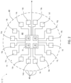
FIG. 3 is a side schematic view of the chemical detection device shown in partial cross-section; -
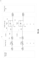
FIG. 4A is a schematic diagram of a chemical sensor array comprising a readout circuit configured to monitor voltage accumulated over an integration period; -
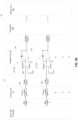
FIG. 4B is a schematic diagram of a chemical sensor array comprising a readout circuit configured to monitor voltage via a dual-slope A/D conversion; -
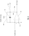
FIG. 5 is a circuit diagram of an amplifier circuit for a chemical sensor; and -
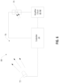
FIG. 6 demonstrates a schematic diagram of a light sensor in accordance with the disclosure. - It is to be understood that the specific devices and processes illustrated in the attached drawings and described in the following specification are simply exemplary embodiments of the inventive concepts defined in the appended claims. Hence, specific dimensions and other physical characteristics relating to the embodiments disclosed herein are not to be considered as limiting, unless the claims expressly state otherwise. As used herein, the term "and/or," when used in a list of two or more items, means that any of the listed items can be employed by itself, or any combination of two or more of the listed items can be employed. For example, if a composition is described as containing components A, B, and/or C, the composition can contain A alone; B alone; C alone; A and B in combination; A and C in combination; B and C in combination; or A, B, and C in combination.
- In this document, relational terms, such as first and second, top and bottom, and the like, are used solely to distinguish one entity or action from another entity or action, without necessarily requiring or implying any actual such relationship or order between such entities or actions. The terms "comprises," "comprising," or any other variation thereof, are intended to cover a non-exclusive inclusion, such that a process, method, article, or apparatus that comprises a list of elements does not include only those elements but may include other elements not expressly listed or inherent to such process, method, article, or apparatus. An element proceeded by "comprises . . . a" does not, without more constraints, preclude the existence of additional identical elements in the process, method, article, or apparatus that comprises the element.
- Referring now to
FIGS. 1-5 , the disclosure provides for a detection system 8 configured to detect a variety of airborne chemical compounds or other measurable conditions. In various implementations, the system 8 may comprise acontroller 10 configured to monitor and control achemical detection device 12. Thechemical detection device 12 is designed to identify a type and/or concentration of various chemicals based on signals communicated from at least onesensor 14 or a plurality ofsensors 14 in anarray 15. In various implementations, the at least onesensor 14 may be incorporated in amodular housing 16 forming thedetection device 12. Accordingly, the disclosure provides for a chemical detection system 8 that may be flexibly applied in a variety of environments to detect one or more chemicals as provided by the following description. - Depending on the application of the system 8, each of the
sensors array 15. Similarly, signals from two or more of thesensors 14 in combination may be interpreted by the system 8 to identify the presence of a chemical or combination of chemicals. Such a detection may be inferred by thecontroller 10 based on an identifying signature or a combination of signals from thesensors 14 that are detected in response to and are representative of the presence of one or more chemicals or compounds. In this way, the system 8 may be scaled or tailored to suit a desired application based on the characteristics of each of thesensors 14. Accordingly, the system 8 may be configured to detect the presence of a variety of chemicals proximate to thearray 15. - The signals output from the
sensors 14 may comprise subtle changes in current. Such small changes, when considered in combination with signal noise and fluctuations that may occur over time, may result in the signals having transient variations that may cause issues identifying the status of thesensors 14. Accordingly, to accurately identify the presence of the chemicals, the system 8 may comprise amonitor circuit 20 configured to detect and communicate information that may be analyzed by thecontroller 10 to determine the resistance of each of thesensors - To effectively measure changes in the chemical composition of the environment proximate to the
array 15, themonitor circuit 20 may be highly sensitive while also being capable of filtering noise related to transient variations output from each of thesensors monitor circuit 20 may comprise anamplifier circuit 22 configured to filter and track the changes in the current output from each of thesensors sensors sensors controller 10 may be configured to activate a readout circuit 24 (e.g. an analog-to-digital converter [ADC]) to read or convert the charges accumulated on theamplifier circuit 22 to digital values. Such values may then be reported by thecontroller 10 and/or stored, such that variations in the resistance of each of thesensors array 15 may be calculated. Further detailed discussion of thesensor array 15 and the monitor circuit is provided in reference toFIG. 4 . - In some implementations as exemplified in
FIG. 4B , thereadout circuit 24 may be implemented with a zero-crossingdetector 24a and acapture timer 24b. The "zero" point may have a magnitude greater than zero in a unipolar power supply implementation. As shown, the integration block is modified, such that thecontroller 10 can select either the unknown current or a reference current of opposite polarity to the unknown. In operation, the unknown is integrated for a known time period. The reference is then integrated until the output of the integrator reaches the zero level. Thecapture timer 24b measures this re-zero time. This re-zero time is directly proportional to the unknown current. This measurement method may be referred to as dual-slope A/D conversion and is capable of very high resolution. Thecapture timer 24b may be implemented in a microprocessor peripheral or other digital hardware. Dual-slope A/D conversion is less complex and low cost than many other A/D conversion methods, but also tends to have a slow conversion rate. For some applications, this combination of high, resolution, low-cost, and slow conversion may be beneficial. - In addition to the sensitive nature of the signals output from the
sensors 14, the operation of each of thesensors sensors 14. Accordingly, the system 8 may further comprise asensor bias circuit 26. Thesensor bias circuit 26 may comprise one or more circuits configured to supply a voltage to each of thesensors controller 10. For example, thesensor bias circuit 26 may comprise a plurality of converters (e.g., digital-to-analog converters [DAC]) configured to generate input signals supplied to each of thesensors controller 10 may be configured to supply independent control signals to each of thesensors sensors array 15 to accurately respond to the presence of chemicals proximate to thearray 15. - Though discussed in reference to specific sensors (e.g. nanofiber chemical sensors), the
chemical detection device 12 may comprise a variety of sensory devices. For example, thechemical detection device 12 may be implemented by a variety of devices including, but not limited to, electrochemical sensors, amperometric gas sensors, carbon monoxide sensors, catalytic bead sensors, thermal conductivity sensors, metal oxide sensors (MOS), infrared (IR) sensors, photoionization detectors (PID), etc. Such sensors may vary in application and, therefore, may be implemented in various combinations to achieve the identification and detection of various chemicals and contaminants that may be present proximate to thedetection device 12. - As discussed herein, the
controller 10 may comprise one or more processors or microcontrollers, a field-programmable gate array (FPGA), application-specific integrated circuit (ASIC), or other processing devices depending on the application. For example, if thesensors 14 of thedevice 12 are not very numerous, a simple processing unit may be sufficient to enable basic detection via the associatedsensors 14. However, if thesensors 14 are more numerous and the corresponding control structure requires more concurrent or programmable operations, the FPGA may be better suited to provide for the operation of thecontroller 10 as discussed herein. As discussed in reference toFIGS. 2 and3 , thedetection device 12 may be configured for more than one sensor, which may suggest the necessity for a complicated control structure. As discussed herein, such a control structure may include an independent supply of bias voltage via thesensor bias circuit 26 as well as independent readout timing control and readout of the charges associated with each of thesensors sensor bias circuit 26 may also include bias resistors, such that a negative or positive signal may be supplied to each of thesensors 14. - In some embodiments, the
controller 10 may further be in communication with one ormore communication circuits 30 configured to communicate with one or more external devices, computers, and/or user interfaces. In some embodiments, thecommunication circuit 30 may correspond to a wired connection (e.g., Universal Serial Bus (USB), Thunderbolt, External Serial Advanced Technology Attachment (eSATA), etc. Additionally, the controller may comprise a wireless network interface. As discussed herein, wireless communication protocols may operate in accordance with communication standards including, but not limited to, ground air cellular towers, global system for mobile communications (GSM), code division multiple access (CDMA), Long Term Evolution (LTE or 4G LTE), etc.; satellite-based communications; and/or variations thereof. Accordingly, thecontroller 10 of the system 8 may be configured to send alerts or signals to various devices configured to communicate via one or more wired or wireless communication protocols. - Referring now to
FIGS. 2 and3 , an example of thedetection device 12 is shown in communication with at least one of thenanofiber chemical sensors 14. Thenanofiber chemical sensor 14 may be configured to sense various chemicals and compounds that may be present in the ambient air proximate to thehousing 16. In some embodiments, the at least onenanofiber chemical sensor 14 may comprise a plurality ofnanofiber chemical sensors 14a-14p. Though identified in this particular example to include sixteensensors 14, the number ofsensors 14 may vary and be adjusted to suit a desired application. In operation, each of the one or morenanofiber chemical sensors 14 may be in communication with thecontroller 10, which may be configured to monitor changes in electrical characteristics for each of thenanofiber sensors 14 in the presence of the various airborne materials. Based on the combination of signals received fromchemical sensors 14, thecontroller 10 may be configured to identify the presence of one or more contaminants proximate to thedetection device 12. - The nanofibers used in the
sensors 14 may be synthesized with specific functional groups that can interact with airborne materials/vapors/particles. The nanofibers are deposited on an interdigitated electrode to form an electrode-nanofiber array. Interaction of the nanofibers with airborne materials changes the measured electrical characteristics of the nanofiber chemical sensor. An increase or decrease in the measured current or effective resistance of each of the nanofiber chemical sensors occurs as a result of these airborne material interactions. - Nanofibers of each of the
sensors 14 with different functional groups have a different response to the same airborne material. By using the plurality ofnanofiber chemical sensors 14 in thearray 15, an identifying response signature can be established by thecontroller 10 for each of a plurality of airborne materials. Accordingly, based on the electrical signals communicated from thearray 15, thecontroller 10 may be configured to detect a variety of conditions that may exist proximate to thesensor array 15. The nanofibers of thesensors 14 may have a proportionately large three-dimensional surface area that is resistant to particulate fouling. In various embodiments, thecontroller 10 may be configured to identify a variety of contaminants. In response to the particular contaminant or family of contaminants identified by thedetection device 12, the system 8 may be configured to respond by outputting information that may assist in the detection or correction of a condition related to the detection. - In various embodiments, the
detection device 12 may be configured to identify a variety of chemicals present in a detection zone or region. Chemicals and compounds that may be detected by the system 8 may be trained or programmed based on electrical signatures received by thecontroller 10 in response to the presence of the chemicals. Examples of chemicals that may be identified and/or detected may include, but are not limited to, Benzaldehyde, Hexane, Acetone, Ethanol, Diesel Fuel, Nitrobenzene, and Formaldehyde. Some examples of explosives and chemical agents that may be detected may include Nitromethane, DNT (Dinitrotoluene), TNT (Trinitrotoluene), ANFO (Ammonium Nitrate Fuel Oil), Ammonium Nitrate, PETN (may detect taggant), RDX (may detect taggant), TATP (Triacetone Triperoxide), H2O2 (Hydrogen Peroxide), TEP (Triethylphosphate), DMMP (Dimethyl methylphosphonate), 2-Chloroethyl ethyl sulfide, Triphosgene, and Methyl Salicylate. Some examples of toxic chemicals that may be detected by thedetection device 12 include, but are not limited to, Chlorine Gas, Ammonia, Hydrogen Peroxide, Sulfur Dioxide, Hydrochloric Acid, TEP (Triethyl Phosphate), Phosphine, Hydrogen Cyanide, Arsine, and Formaldehyde. In some examples, the detection device may also be configured to detect one or more chemicals commonly found in consumer foods and/or goods including, but not limited to, Trichloroanisole, Melamine, Trimethylamine, Limonene, Pinene, Linalyl acetate, Menthol, Menthone, and Linalool. Thedevice 12 may additionally be configured to detect various amines including, but not limited to, N-Methylphenethylam-lamine, Phenethylamine, Methylamine, Aniline, Triethylamine, and Diethylamine. Accordingly, based on the detection of each of the chemicals detected by thecontroller 10, a signal or information may be communicated via thecommunication circuit 30 to indicate the chemical presence. - Referring now to
FIG. 3 , thechemical sensors 14a-14p of thedetection device 12 may be arranged in any manner and may be disposed in aninner chamber 42 of thehousing 16 having a plurality of air vents 45. The air vents 45 may provide for ambient and/or forced air to flow into theinner chamber 42. In this configuration, updated air samples flow past thechemical sensors 14a-14p providing consistently updated monitoring of the chemical particulates present in the air. In various implementations, the air vents 45 may be large enough and/or numerous enough to allow the ambient air to flow into theinner chamber 42 without restriction. Thecontroller 10 may be in communication with various systems and/or controllers that may be associated with additional devices and/or interfaces via thecommunication circuit 30. In various implementations, thecommunication circuit 30 may correspond to a wired and/or wireless connection. Accordingly, the system 8 may be configured to communicate one or more warnings, instructions, and/or additional information to a user, device, or remote server in response to the detection of one or more chemicals via thedetection device 12. - Common chemicals and corresponding odors that may be detected by the
device 12 may vary widely. For example, thedevice 12 may be configured to identify a variety of odors including, but not limited to, perfumes, feces, fish, skunk, pet odor, decaying biological material, methane, hydrogen sulfide, body odor (body-related bacterial odor), smoke, alcohol, bodily fluids, vomit, etc. Some of these odors may relate to comfort issues while others could present health issues or security concerns to those exposed. Accordingly, the system 8 may additionally communicate a concentration of the chemicals detected by thedevice 12 via thecommunication circuit 30 of thecontroller 10. - Additionally, the
detection device 12 may be configured to detect and identify a variety of chemicals that may generally be considered dangerous, which may or may not cause a significant odor. Examples of such chemicals or sources of such chemicals may be allergens including, but not limited to, peanuts, soy, perfumes, smog, etc. Additional examples of chemicals or sources of such chemicals may include, but are not limited to, explosives, gun powder, accelerants, carbon dioxide, carbon monoxide, volatile organic compounds (VOCs), drugs (e.g. methamphetamine, alcohol), smog, smoke, exhaust, etc. In response to the detection of such chemicals, the system 8 may respond in different ways, particularly in comparison to the detection of chemicals that may not be dangerous to users or individuals in the area of thedetection device 12. - Referring now to
FIG. 4A , a diagram of thesensor array 15 is shown in conductive communication with thesensor bias circuit 26. As previously described, thesensor bias circuit 26 may be configured to supply an analog voltage to each of thesensors controller 10. For example, thesensor bias circuit 26 may comprise a plurality of digital-to-analog converters (DACs) configured to generate voltages ranging from approximately ±15V in response to digital input signals supplied by thecontroller 10. In this configuration, thecontroller 10 may be configured to supply independent control signals to control the bias voltage delivered to each of thesensors sensors sensors sensors array 15 to accurately detect the chemicals proximate to thearray 15. - As depicted, the
sensors 14 of thesensor array 15 may correspond to chemiresistors, which are shown modeled as variable resistors. Thesensors 14 may be formed of nanofibers disposed between interdigitated fingers of electrode pairs. The nanofibers may form a porous structure across the electrode pairs configured to capture targeted molecules in the air proximate to thedetection device 12. When the nanofibers come in contact with target analytes or chemicals, a change in the electrochemical characteristics of the nanofibers may occur. The change in electrochemical characteristics may result in increases or decreases in the signal output to theamplifier circuit 22. An input side of the electrode pair may be connected to thesensor bias circuit 26, and an output side of the electrode pair may be connected to the amplifier circuit 22 (e.g., 22a, 22b, etc.). As shown, theamplifier circuits 22 connected to thesensors 14 may form anamplifier array 52. - In operation, the
controller 10 may be configured to control an exposure of each of thesensors sensors different sensors 14 of thesensor array 15. The small changes in current may be accumulated over exposure times by acapacitor 54 of each of the amplifier circuits 22a, 22b, etc. Once the exposure time has elapsed, thecontroller 10 may control afirst switch 56a. Thefirst switch 56a may be configured to cause the accumulated charge to be held in thecapacitor 54, such that the corresponding charge may be read out by the readout circuit 24 (e.g. an analog-to-digital converter [ADC]) and communicated to thecontroller 10 from an op-amp 58 of theamplifier circuit 22. - Once the charge is read out from the
amplifier circuit 22, thecontroller 10 may be configured to control asecond switch 56b to reset or discharge thecapacitor 54, such that the accumulation of the current may again be measured over an integration period. In this way, the accumulated charges of each of thesensors 14 of thearray 15 may be monitored and processed by thecontroller 10 and/or additional computers or controllers to determine variations in resistance in the resistance of thesensors 14. Based on the variations in the resistances of thesensors 14 and the corresponding changes in the charges accumulated in the capacitors, thecontroller 10 may determine or infer the chemical compositions or types of materials to which thedetection device 12 is exposed. As discussed herein, thecontroller 10 may be configured to independently adjust the duration and timing (e.g. frequency) of the integration period of each of thesensors 14. Additionally, thecontroller 10 may adjust the integration periods of theamplifier circuits 22 over time in order to ensure that the accumulated charges are sufficient to measure and limited to avoid saturation of the capacity of thecapacitor 54. In this way, thecontroller 10 may monitor and compute the changes in the resistance of each of thesensors 14. - As depicted in
FIG. 4A , theamplifier circuits 22 each comprise the op-amp 58 conductively connected to the bias output at an inverting input. Thefirst switch 56a (e.g. a hold switch) may be disposed between the bias output and the inverting input allowing thecontroller 10 to selectively disconnect the bias output from theamplifier circuit 22. The non-inverting input of the op-amp 58 may be connected to the ground, and the output may be in connection with thereadout circuit 24. Thesecond switch 56b (e.g. a reset switch) and thecapacitor 54 may be connected in parallel from the inverting input to the output of the op-amp 58. In this configuration, each of the amplifier circuits 22a, 22b, etc. may be configured to integrate a charge supplied by each of thesensors readout circuit 24. The charge value is representative of a resistance of each of thesensors sensors 14 over the integration period or a time interval, which is also controlled by and known by thecontroller 10. In this way, the resistance of each of thesensors controller 10 to infer or calculate a concentration of a chemical compound proximate to thedetection device 12 while filtering transient spikes and noise that may otherwise cause significant error. - The chemical composition of the airborne material detected by the
sensors sensors controller 10 to a table or library of resistance characteristics for various chemical compositions. In this way, the controller may compare the detected resistances to the resistance characteristics to identify the specific chemical composition and distinguish the composition from various chemical compositions that may be identified by the system 8. In other words, the system 8 may monitor and compare the resistances of thesensors sensors sensors sensors sensors - Referring now to
FIG. 4B , thereadout circuit 24 may be implemented with a zero-crossingdetector 24a (e.g. comparator) and acapture timer 24b. As shown, the integration block is modified such that thecontroller 10 can select either the unknown current or a reference current of opposite polarity to the unknown via a three-way switch, which may be referred to as anintegration switch 56c. Theintegration switch 56c is in connection with the inverting input of the op-amp 58. In operation, the unknown current is integrated for a known time period. The reference is then integrated until the output of the integrator reaches the zero level. Thecapture timer 24b measures this re-zero time. This re-zero time is directly proportional to the unknown current. - Referring now to
FIG. 5 , a circuit diagram of anamplifier circuit 62 as discussed herein is shown. Theamplifier circuit 62 may be similar to theamplifier circuit 22 and accordingly, the description of theamplifier circuit 62 may focus on the aspects that may differ, and like reference numerals may be used to refer to like parts. Theamplifier circuit 62 may comprise the op-amp 58 conductively connecting the bias output to an inverting input of the op-amp 58. The non-inverting input of the op-amp 58 may be connected to a ground. Thesecond switch 56b (e.g. a reset switch) and thecapacitor 54 may be connected in parallel from the inverting input to the output of the op-amp 58. Thefirst switch 56a may be connected in series between the output of the op-amp 58 and the parallel connection of thecapacitor 54 with thesecond switch 56b. - Additionally, a
third switch 56c may be configured to selectively connect thecapacitor 54 to a reference voltage Vref. Thethird switch 56c may also be controlled by thecontroller 10 and may be connected in series between an input of the reference voltage Vref and the parallel connection of thecapacitor 54 with thesecond switch 56b. Finally, theamplifier circuit 62 may further comprise a chargingswitch 56d connected from the inverting input of the op-amp 58 to the ground. The operation of the chargingswitch 56d may also be controlled by thecontroller 10 and provide for the control of the charging of thecapacitor 54. Accordingly, the disclosure may implement theamplifier circuit 62 to monitor a charge generated by the at least one sensor over a time interval as provided by the disclosure. - Referring now to
FIG. 6 , a schematic diagram of alight detection system 68 is shown demonstrating a photosensor 70 (e.g. a photodiode) configured to monitor a light transmitted from an emitter 72 (e.g. a light-emitting diode [LED], halogen bulb, xenon bulb, etc.). Though discussed in reference to theemitter 72, thephotosensor 70 may similarly be applied to monitor an environmental light source or daylight condition. In operation, a controller 74 may be configured to activate theemitter 72 and monitor the light received by thephotosensor 70. Similar to thesensors 14 of thedetection device 12, thephotosensor 70 may vary in output current in response to a local environment. The photosensor 70 may react by varying in photocurrent output to theamplifier circuit photosensor 70. In this way, the controller 74 may detect fluctuations in the light received by the photosensor 70 from theemitter 72. In some implementations, the controller 74 may infer or determine the presence of a particle in anopen region 76 between theemitter 72 and thephotosensor 70 and make inferences as to the quality, condition, and/or transmittance or transparency of air in theopen region 76. Similarly, the controller 74 may be configured to determine a brightness or relative luminance of a local environment in instances where theemitter 72 is not controlled by the controller 74 and instead corresponds to an environmental light source or external light source (e.g. the sun, streetlights, etc.). Accordingly, the disclosure provides for a flexible solution that may be implemented in a variety of beneficial implementations. - As discussed herein the light detection system may correspond to a smoke or particulate sensor as discussed in
U.S. Pat. No. 6,876,305 , entitled "COMPACT PARTICLE SENSOR,"U.S. Pat. No. 6,653,942 , entitled "SMOKE DETECTOR,"U.S. Pat. No. 6,326,897 , entitled "SMOKE DETECTOR," andU.S. Pat. No. 6,225,910 , entitled "SMOKE DETECTOR,". - It will be understood by one having ordinary skill in the art that construction of the described device and other components may not be limited to any specific material. Other exemplary embodiments of the device disclosed herein may be formed from a wide variety of materials unless described otherwise herein.
- For purposes of this disclosure, the term "coupled" (in all of its forms, couple, coupling, coupled, etc.) generally means the joining of two components (electrical or mechanical) directly or indirectly to one another. Such joining may be stationary in nature or movable in nature. Such joining may be achieved with the two components (electrical or mechanical) and any additional intermediate members being integrally formed as a single unitary body with one another or with the two components. Such joining may be permanent or may be removable or releasable unless otherwise stated.
- It is also important to note that the construction and arrangement of the elements of the device as shown in the exemplary embodiments is illustrative only. Although only a few embodiments of the present innovations have been described in detail in this disclosure, those skilled in the art who review this disclosure will readily appreciate that many modifications are possible (e.g., variations in sizes, dimensions, structures, shapes, and proportions of the various elements, values of parameters, mounting arrangements, use of materials, colors, orientations, etc.) without materially departing from the novel teachings and advantages of the subject matter recited. For example, elements shown as integrally formed may be constructed of multiple parts or elements shown as multiple parts may be integrally formed, the operation of the interfaces may be reversed or otherwise varied, the length or width of the structures and/or members or connector or other elements of the system may be varied, the nature or number of adjustment positions provided between the elements may be varied. It should be noted that the elements and/or assemblies of the system may be constructed from any of a wide variety of materials that provide sufficient strength or durability, in any of a wide variety of colors, textures, and combinations. Accordingly, all such modifications are intended to be included within the scope of the present innovations.
- It will be understood that any described processes or steps within described processes may be combined with other disclosed processes or steps to form structures within the scope of the present device. The exemplary structures and processes disclosed herein are for illustrative purposes and are not to be construed as limiting.
- It is also to be understood that variations and modifications can be made on the aforementioned structure without departing from the concepts of the present invention, and further it is to be understood that such concepts are intended to be covered by the following claims unless these claims by their language expressly state otherwise.
- The above description is considered that of the illustrated embodiments only. Modifications of the device will occur to those skilled in the art and to those who make or use the device. Therefore, it is understood that the embodiments shown in the drawings and described above are merely for illustrative purposes and not intended to limit the scope of the device, which is defined by the following claims as interpreted according to the principles of patent law, including the Doctrine of Equivalents.
Claims (11)
- A detection system (8) comprising:at least one sensor (14) configured to measure a presence of airborne particles,wherein the at least one sensor (14) comprises a nanofiber chemical sensor (14) for sensing a chemical composition of the airborne particles, andwherein the nanofiber chemical sensor (14) comprises a variable resistance that varies in response to a concentration of the chemical composition of the airborne particles;at least one amplifier circuit (22) in communication with the at least one sensor (14),
wherein the amplifier circuit (22) is configured to monitor a charge generated by the at least one sensor (14) over a time interval; anda controller (10) configured to:monitor the charge accumulated in the at least one amplifier circuit (22) from the at least one sensor (14) at the time interval; andin response to the charge of the at least one amplifier circuit (22), detect the presence of the airborne particles,wherein the controller (10) is further configured to:
detect the concentration of the chemical composition in response to identifying changes in the variable resistance, wherein the changes in the variable resistance are determined based on the charge of the at least one amplifier circuit (22) and a voltage potential of a bias voltage supplied to the at least one nanofiber chemical sensor (14). - The system according to claim 1, further comprising a light source wherein the at least one sensor (14) is configured to detect light emitted from the light source.
- The system according to any one of claims 1-2, wherein the at least one amplifier circuit (22) comprises an op-amp (58) conductively connected to a sensor output from the at least one sensor (14), wherein a capacitor (54) and a switch are connected to the sensor output from the at least one sensor (14) in parallel with the op-amp (58).
- The system according to claim 3, wherein the sensor output is in connection with an inverting input of the op-amp (58).
- The system according to any one of claims 1-4, wherein the at least one sensor (14) comprises a plurality of nanofiber chemical sensors (14), and further comprising:
a bias circuit (26) configured to supply a plurality of bias voltages to each of the plurality of nanofiber chemical sensors (14). - The system according to claim 5, wherein the controller (10) is further configured to:
control the bias circuit (26) to supply the plurality of bias voltages as different voltages to each of the plurality of chemical sensors (14). - The system according to claim 5, wherein the bias circuit (26) comprises a plurality of digital-to-analog converters configured to supply the plurality of bias voltages as different voltages to the plurality of chemical sensors (14) in response to control signal supplied from the controller (10).
- The system according to claim 5, wherein the at least one amplifier circuit (22) comprises a plurality of amplifier circuits (22) in connection with each of the chemical sensors (14), wherein the controller (10) is further configured to:monitor the charge accumulated in the amplifier circuits (22) from the at least one sensor (14) at the time interval; anddetermine the resistance of each of the chemical sensors (14) based on the charge of the amplifier circuits (22) and voltage values of the plurality of bias voltages.
- The system according to claim 8, wherein the controller (10) is further configured to:
detect a concentration of the chemical composition of the airborne particles based on the determined resistance of one or more of the chemical sensors (14). - The system according to claim 8, wherein the controller (10) is further configured to:independently control the time interval for an integration period for each of the plurality of amplifier circuits (22), thereby independently controlling the integration period for each of the chemical sensors (14) in connection with the corresponding amplifier circuits (22);wherein the controller (10) is further configured to:
distinguish the chemical composition of the airborne particles among a plurality of chemical compositions in response to combinations of the resistances of the chemical sensors (14). - A method for detecting a presence of airborne particles comprising:supplying a plurality of bias voltages to a plurality of chemical sensors (14) configured to measure a presence of airborne particles,wherein the plurality of chemical sensors (14) comprises a nanofiber chemical sensor (14) for sensing a chemical composition of the airborne particles, andwherein the nanofiber chemical sensor (14) comprises a variable resistance that varies in response to a concentration of the chemical composition of the airborne particles;receiving and accumulating current from each of the chemical sensors (14) with a corresponding amplifier circuit (22);monitoring charges accumulated in the amplifier circuits (22) from each of the chemical sensors (14) over a plurality of corresponding accumulation periods;determining the resistance of each of the chemical sensors (14) based on the charges of the amplifier circuits (22) and voltage values of the plurality of bias voltages; anddetecting the concentration of the chemical composition in response to identifying changes in the resistance, wherein the changes in the resistance are determined based on the charge of the amplifier circuits (22) and a voltage potential of a bias voltage supplied to the chemical sensors (14).
Applications Claiming Priority (2)
| Application Number | Priority Date | Filing Date | Title |
|---|---|---|---|
| US201962935295P | 2019-11-14 | 2019-11-14 | |
| PCT/IB2020/060672 WO2021094981A1 (en) | 2019-11-14 | 2020-11-12 | System and methods for chemical detection and amplification |
Publications (3)
| Publication Number | Publication Date |
|---|---|
| EP4058780A1 EP4058780A1 (en) | 2022-09-21 |
| EP4058780A4 EP4058780A4 (en) | 2023-01-11 |
| EP4058780B1 true EP4058780B1 (en) | 2025-03-26 |
Family
ID=75908665
Family Applications (1)
| Application Number | Title | Priority Date | Filing Date |
|---|---|---|---|
| EP20888308.2A Active EP4058780B1 (en) | 2019-11-14 | 2020-11-12 | System and methods for chemical detection and amplification |
Country Status (4)
| Country | Link |
|---|---|
| US (1) | US11181497B2 (en) |
| EP (1) | EP4058780B1 (en) |
| CN (1) | CN114729873B (en) |
| WO (1) | WO2021094981A1 (en) |
Families Citing this family (6)
| Publication number | Priority date | Publication date | Assignee | Title |
|---|---|---|---|---|
| US10241095B2 (en) | 2015-11-23 | 2019-03-26 | Sentelligence, Inc. | Multi-component gas and vapor monitoring sensor |
| US20170205338A1 (en) | 2016-01-18 | 2017-07-20 | Sentelligence, Inc. | Sensor system for multi-component fluids |
| CN111263958B (en) * | 2017-10-30 | 2022-05-27 | 开利公司 | Compensator in detector device |
| EP4285349A4 (en) | 2021-01-29 | 2025-04-02 | Saam, Inc. | SENSOR FUSION FOR FIRE DETECTION AND AIR QUALITY MONITORING |
| EP4318039A4 (en) | 2021-06-01 | 2024-09-25 | Samsung Electronics Co., Ltd. | ELECTRONIC DEVICE AND METHOD FOR CARRYING OUT A DISTANCE MEASUREMENT PROCESS |
| USD1001663S1 (en) | 2021-12-30 | 2023-10-17 | Gentex Corporation | Chemical detector |
Family Cites Families (15)
| Publication number | Priority date | Publication date | Assignee | Title |
|---|---|---|---|---|
| GB2193570B (en) * | 1986-08-05 | 1990-01-24 | Secr Defence | Analyser for airborne particles |
| US4847783A (en) * | 1987-05-27 | 1989-07-11 | Richard Grace | Gas sensing instrument |
| DE4436938A1 (en) | 1994-04-27 | 1996-04-18 | Auto Electronics Corp | Wet and wind-protected gas sensor |
| US6876305B2 (en) | 1999-12-08 | 2005-04-05 | Gentex Corporation | Compact particle sensor |
| US6225910B1 (en) | 1999-12-08 | 2001-05-01 | Gentex Corporation | Smoke detector |
| WO2004019294A2 (en) | 2002-08-23 | 2004-03-04 | General Electric Company | Rapidly responding, false detection immune alarm signal producing smoke detector |
| US6936828B2 (en) * | 2003-02-14 | 2005-08-30 | Honeywell International Inc. | Particle detection system and method |
| US20120143515A1 (en) * | 2006-09-28 | 2012-06-07 | Smiths Detection Inc. | Multi-detector gas identification system |
| US8452489B2 (en) | 2007-01-10 | 2013-05-28 | Koninklijke Philips Electronics N.V. | Controlling system for controlling an air handling system |
| EP2380001B1 (en) * | 2008-12-18 | 2015-02-11 | Azbil Corporation | Compact detector for simultaneous particle size and fluorescence detection |
| WO2014146714A1 (en) * | 2013-03-21 | 2014-09-25 | Barbetta Marco | Method and apparatus for detecting breath alcohol concentration based on acoustic breath sampler |
| JP2017116287A (en) * | 2015-12-21 | 2017-06-29 | パナソニックIpマネジメント株式会社 | Particle detection sensor |
| KR101936475B1 (en) * | 2016-12-07 | 2019-01-08 | 현대자동차주식회사 | Sensor for measuring Particulate Matter With function Suppling bias voltage |
| US20180348109A1 (en) * | 2017-06-01 | 2018-12-06 | Delphi Technologies Ip Limited | Particulate matter detection system and method |
| WO2019204538A1 (en) * | 2018-04-18 | 2019-10-24 | Gentex Corporation | Nanofiber smoke detection calibration |
-
2020
- 2020-11-12 WO PCT/IB2020/060672 patent/WO2021094981A1/en not_active Ceased
- 2020-11-12 CN CN202080078921.3A patent/CN114729873B/en active Active
- 2020-11-12 US US17/095,808 patent/US11181497B2/en active Active
- 2020-11-12 EP EP20888308.2A patent/EP4058780B1/en active Active
Also Published As
| Publication number | Publication date |
|---|---|
| EP4058780A1 (en) | 2022-09-21 |
| WO2021094981A1 (en) | 2021-05-20 |
| US20210148844A1 (en) | 2021-05-20 |
| CN114729873A (en) | 2022-07-08 |
| EP4058780A4 (en) | 2023-01-11 |
| US11181497B2 (en) | 2021-11-23 |
| CN114729873B (en) | 2025-10-10 |
Similar Documents
| Publication | Publication Date | Title |
|---|---|---|
| US11181497B2 (en) | System and methods for chemical detection and amplification | |
| US11714073B2 (en) | Photoionization detector automated zero level calibration | |
| Utriainen et al. | Combining miniaturized ion mobility spectrometer and metal oxide gas sensor for the fast detection of toxic chemical vapors | |
| AU2010230254B2 (en) | Selective detector for carbon monoxide | |
| Scorsone et al. | Development of an electronic nose for fire detection | |
| JP5643511B2 (en) | Multi-detector gas identification system | |
| Fung et al. | Wearable environmental monitor to quantify personal ambient volatile organic compound exposures | |
| EP3186628A1 (en) | Sensor system and sensing method | |
| KR20120135909A (en) | Flow regulating system and monitoring device comprising said flow regulating system for the detection of air borne analytes | |
| Illahi et al. | Electronic nose technology and application: A review | |
| Huang et al. | Machine learning-driven gas identification in gas sensors | |
| EP1907786A2 (en) | Trainable sensors and network | |
| US11423761B2 (en) | Connected monitoring system | |
| Sadeghifard et al. | A new embedded e-nose system to identify smell of smoke | |
| Bakar et al. | Electronic nose purging technique for confined space application | |
| Chowdhury et al. | Role of gas sensor an integrated part of e-nose for online monitoring of air grade | |
| Lozanoa et al. | Detection of pollutants in water using a wireless network of electronic noses | |
| RU213351U1 (en) | THERMOCHEMICAL GAS DETECTOR | |
| Manser et al. | Sensing Prototype for Detecting Ethanol and Acetone Vapor Mixtures Using Gas Sensors | |
| EP0835441A1 (en) | Gas sensor arrangement | |
| Cali et al. | Odorant binding proteins based sniffing device for detection of tobacco | |
| Brezmes et al. | Application of artificial neural networks to the design and implementation of electronic olfactory systems | |
| Pereira-Rodrigues et al. | Reliable Monitoring Of Low Concentrations Of Hs In Changing Environments | |
| Groves | Sensors in the Measurement of Toxic Gases in the Air | |
| Romain et al. | Assessment of odour annoyance by e-nose in the field: some results |
Legal Events
| Date | Code | Title | Description |
|---|---|---|---|
| STAA | Information on the status of an ep patent application or granted ep patent |
Free format text: STATUS: THE INTERNATIONAL PUBLICATION HAS BEEN MADE |
|
| PUAI | Public reference made under article 153(3) epc to a published international application that has entered the european phase |
Free format text: ORIGINAL CODE: 0009012 |
|
| STAA | Information on the status of an ep patent application or granted ep patent |
Free format text: STATUS: REQUEST FOR EXAMINATION WAS MADE |
|
| 17P | Request for examination filed |
Effective date: 20220609 |
|
| AK | Designated contracting states |
Kind code of ref document: A1 Designated state(s): AL AT BE BG CH CY CZ DE DK EE ES FI FR GB GR HR HU IE IS IT LI LT LU LV MC MK MT NL NO PL PT RO RS SE SI SK SM TR |
|
| REG | Reference to a national code |
Ref country code: DE Ref legal event code: R079 Free format text: PREVIOUS MAIN CLASS: G01N0015140000 Ipc: G01N0033000000 Ref document number: 602020048519 Country of ref document: DE |
|
| A4 | Supplementary search report drawn up and despatched |
Effective date: 20221208 |
|
| RIC1 | Information provided on ipc code assigned before grant |
Ipc: G01N 15/06 20060101ALN20221202BHEP Ipc: G01N 33/00 20060101AFI20221202BHEP |
|
| DAV | Request for validation of the european patent (deleted) | ||
| DAX | Request for extension of the european patent (deleted) | ||
| P01 | Opt-out of the competence of the unified patent court (upc) registered |
Effective date: 20230503 |
|
| STAA | Information on the status of an ep patent application or granted ep patent |
Free format text: STATUS: EXAMINATION IS IN PROGRESS |
|
| 17Q | First examination report despatched |
Effective date: 20240925 |
|
| GRAP | Despatch of communication of intention to grant a patent |
Free format text: ORIGINAL CODE: EPIDOSNIGR1 |
|
| STAA | Information on the status of an ep patent application or granted ep patent |
Free format text: STATUS: GRANT OF PATENT IS INTENDED |
|
| RIC1 | Information provided on ipc code assigned before grant |
Ipc: G01N 15/06 20060101ALN20241128BHEP Ipc: G01N 33/00 20060101AFI20241128BHEP |
|
| INTG | Intention to grant announced |
Effective date: 20241210 |
|
| GRAS | Grant fee paid |
Free format text: ORIGINAL CODE: EPIDOSNIGR3 |
|
| GRAA | (expected) grant |
Free format text: ORIGINAL CODE: 0009210 |
|
| STAA | Information on the status of an ep patent application or granted ep patent |
Free format text: STATUS: THE PATENT HAS BEEN GRANTED |
|
| AK | Designated contracting states |
Kind code of ref document: B1 Designated state(s): AL AT BE BG CH CY CZ DE DK EE ES FI FR GB GR HR HU IE IS IT LI LT LU LV MC MK MT NL NO PL PT RO RS SE SI SK SM TR |
|
| REG | Reference to a national code |
Ref country code: GB Ref legal event code: FG4D |
|
| REG | Reference to a national code |
Ref country code: CH Ref legal event code: EP |
|
| REG | Reference to a national code |
Ref country code: DE Ref legal event code: R096 Ref document number: 602020048519 Country of ref document: DE |
|
| REG | Reference to a national code |
Ref country code: IE Ref legal event code: FG4D |
|
| PG25 | Lapsed in a contracting state [announced via postgrant information from national office to epo] |
Ref country code: RS Free format text: LAPSE BECAUSE OF FAILURE TO SUBMIT A TRANSLATION OF THE DESCRIPTION OR TO PAY THE FEE WITHIN THE PRESCRIBED TIME-LIMIT Effective date: 20250626 |
|
| PG25 | Lapsed in a contracting state [announced via postgrant information from national office to epo] |
Ref country code: FI Free format text: LAPSE BECAUSE OF FAILURE TO SUBMIT A TRANSLATION OF THE DESCRIPTION OR TO PAY THE FEE WITHIN THE PRESCRIBED TIME-LIMIT Effective date: 20250326 |
|
| REG | Reference to a national code |
Ref country code: LT Ref legal event code: MG9D |
|
| PG25 | Lapsed in a contracting state [announced via postgrant information from national office to epo] |
Ref country code: NO Free format text: LAPSE BECAUSE OF FAILURE TO SUBMIT A TRANSLATION OF THE DESCRIPTION OR TO PAY THE FEE WITHIN THE PRESCRIBED TIME-LIMIT Effective date: 20250626 |
|
| PG25 | Lapsed in a contracting state [announced via postgrant information from national office to epo] |
Ref country code: HR Free format text: LAPSE BECAUSE OF FAILURE TO SUBMIT A TRANSLATION OF THE DESCRIPTION OR TO PAY THE FEE WITHIN THE PRESCRIBED TIME-LIMIT Effective date: 20250326 |
|
| PG25 | Lapsed in a contracting state [announced via postgrant information from national office to epo] |
Ref country code: LV Free format text: LAPSE BECAUSE OF FAILURE TO SUBMIT A TRANSLATION OF THE DESCRIPTION OR TO PAY THE FEE WITHIN THE PRESCRIBED TIME-LIMIT Effective date: 20250326 |
|
| PG25 | Lapsed in a contracting state [announced via postgrant information from national office to epo] |
Ref country code: BG Free format text: LAPSE BECAUSE OF FAILURE TO SUBMIT A TRANSLATION OF THE DESCRIPTION OR TO PAY THE FEE WITHIN THE PRESCRIBED TIME-LIMIT Effective date: 20250326 Ref country code: GR Free format text: LAPSE BECAUSE OF FAILURE TO SUBMIT A TRANSLATION OF THE DESCRIPTION OR TO PAY THE FEE WITHIN THE PRESCRIBED TIME-LIMIT Effective date: 20250627 |
|
| REG | Reference to a national code |
Ref country code: NL Ref legal event code: MP Effective date: 20250326 |
|
| PG25 | Lapsed in a contracting state [announced via postgrant information from national office to epo] |
Ref country code: NL Free format text: LAPSE BECAUSE OF FAILURE TO SUBMIT A TRANSLATION OF THE DESCRIPTION OR TO PAY THE FEE WITHIN THE PRESCRIBED TIME-LIMIT Effective date: 20250326 |
|
| PG25 | Lapsed in a contracting state [announced via postgrant information from national office to epo] |
Ref country code: SE Free format text: LAPSE BECAUSE OF FAILURE TO SUBMIT A TRANSLATION OF THE DESCRIPTION OR TO PAY THE FEE WITHIN THE PRESCRIBED TIME-LIMIT Effective date: 20250326 |
|
| REG | Reference to a national code |
Ref country code: AT Ref legal event code: MK05 Ref document number: 1779420 Country of ref document: AT Kind code of ref document: T Effective date: 20250326 |
|
| PG25 | Lapsed in a contracting state [announced via postgrant information from national office to epo] |
Ref country code: SM Free format text: LAPSE BECAUSE OF FAILURE TO SUBMIT A TRANSLATION OF THE DESCRIPTION OR TO PAY THE FEE WITHIN THE PRESCRIBED TIME-LIMIT Effective date: 20250326 |
|
| PG25 | Lapsed in a contracting state [announced via postgrant information from national office to epo] |
Ref country code: ES Free format text: LAPSE BECAUSE OF FAILURE TO SUBMIT A TRANSLATION OF THE DESCRIPTION OR TO PAY THE FEE WITHIN THE PRESCRIBED TIME-LIMIT Effective date: 20250326 Ref country code: PT Free format text: LAPSE BECAUSE OF FAILURE TO SUBMIT A TRANSLATION OF THE DESCRIPTION OR TO PAY THE FEE WITHIN THE PRESCRIBED TIME-LIMIT Effective date: 20250728 |
|
| PG25 | Lapsed in a contracting state [announced via postgrant information from national office to epo] |
Ref country code: IT Free format text: LAPSE BECAUSE OF FAILURE TO SUBMIT A TRANSLATION OF THE DESCRIPTION OR TO PAY THE FEE WITHIN THE PRESCRIBED TIME-LIMIT Effective date: 20250326 Ref country code: PL Free format text: LAPSE BECAUSE OF FAILURE TO SUBMIT A TRANSLATION OF THE DESCRIPTION OR TO PAY THE FEE WITHIN THE PRESCRIBED TIME-LIMIT Effective date: 20250326 |
|
| PG25 | Lapsed in a contracting state [announced via postgrant information from national office to epo] |
Ref country code: AT Free format text: LAPSE BECAUSE OF FAILURE TO SUBMIT A TRANSLATION OF THE DESCRIPTION OR TO PAY THE FEE WITHIN THE PRESCRIBED TIME-LIMIT Effective date: 20250326 |
|
| PG25 | Lapsed in a contracting state [announced via postgrant information from national office to epo] |
Ref country code: EE Free format text: LAPSE BECAUSE OF FAILURE TO SUBMIT A TRANSLATION OF THE DESCRIPTION OR TO PAY THE FEE WITHIN THE PRESCRIBED TIME-LIMIT Effective date: 20250326 |
|
| PG25 | Lapsed in a contracting state [announced via postgrant information from national office to epo] |
Ref country code: RO Free format text: LAPSE BECAUSE OF FAILURE TO SUBMIT A TRANSLATION OF THE DESCRIPTION OR TO PAY THE FEE WITHIN THE PRESCRIBED TIME-LIMIT Effective date: 20250326 |
|
| PG25 | Lapsed in a contracting state [announced via postgrant information from national office to epo] |
Ref country code: SK Free format text: LAPSE BECAUSE OF FAILURE TO SUBMIT A TRANSLATION OF THE DESCRIPTION OR TO PAY THE FEE WITHIN THE PRESCRIBED TIME-LIMIT Effective date: 20250326 |
|
| PG25 | Lapsed in a contracting state [announced via postgrant information from national office to epo] |
Ref country code: IS Free format text: LAPSE BECAUSE OF FAILURE TO SUBMIT A TRANSLATION OF THE DESCRIPTION OR TO PAY THE FEE WITHIN THE PRESCRIBED TIME-LIMIT Effective date: 20250726 |
|
| REG | Reference to a national code |
Ref country code: DE Ref legal event code: R097 Ref document number: 602020048519 Country of ref document: DE |
|
| PGFP | Annual fee paid to national office [announced via postgrant information from national office to epo] |
Ref country code: DE Payment date: 20251022 Year of fee payment: 6 |
|
| PGFP | Annual fee paid to national office [announced via postgrant information from national office to epo] |
Ref country code: GB Payment date: 20251023 Year of fee payment: 6 |
|
| PG25 | Lapsed in a contracting state [announced via postgrant information from national office to epo] |
Ref country code: DK Free format text: LAPSE BECAUSE OF FAILURE TO SUBMIT A TRANSLATION OF THE DESCRIPTION OR TO PAY THE FEE WITHIN THE PRESCRIBED TIME-LIMIT Effective date: 20250326 |
|
| PGFP | Annual fee paid to national office [announced via postgrant information from national office to epo] |
Ref country code: FR Payment date: 20251022 Year of fee payment: 6 |
|
| PG25 | Lapsed in a contracting state [announced via postgrant information from national office to epo] |
Ref country code: CZ Free format text: LAPSE BECAUSE OF FAILURE TO SUBMIT A TRANSLATION OF THE DESCRIPTION OR TO PAY THE FEE WITHIN THE PRESCRIBED TIME-LIMIT Effective date: 20250326 |
|
| PLBE | No opposition filed within time limit |
Free format text: ORIGINAL CODE: 0009261 |
|
| STAA | Information on the status of an ep patent application or granted ep patent |
Free format text: STATUS: NO OPPOSITION FILED WITHIN TIME LIMIT |
|
| REG | Reference to a national code |
Ref country code: CH Ref legal event code: L10 Free format text: ST27 STATUS EVENT CODE: U-0-0-L10-L00 (AS PROVIDED BY THE NATIONAL OFFICE) Effective date: 20260211 |
|
| 26N | No opposition filed |
Effective date: 20260105 |