EP4058099B1 - Equipment for the control of biomedical devices during extracorporeal circulation and related system - Google Patents
Equipment for the control of biomedical devices during extracorporeal circulation and related system Download PDFInfo
- Publication number
- EP4058099B1 EP4058099B1 EP20821379.3A EP20821379A EP4058099B1 EP 4058099 B1 EP4058099 B1 EP 4058099B1 EP 20821379 A EP20821379 A EP 20821379A EP 4058099 B1 EP4058099 B1 EP 4058099B1
- Authority
- EP
- European Patent Office
- Prior art keywords
- control unit
- emergency
- equipment
- biomedical
- unit
- Prior art date
- Legal status (The legal status is an assumption and is not a legal conclusion. Google has not performed a legal analysis and makes no representation as to the accuracy of the status listed.)
- Active
Links
Images

Classifications
-
- A—HUMAN NECESSITIES
- A61—MEDICAL OR VETERINARY SCIENCE; HYGIENE
- A61M—DEVICES FOR INTRODUCING MEDIA INTO, OR ONTO, THE BODY; DEVICES FOR TRANSDUCING BODY MEDIA OR FOR TAKING MEDIA FROM THE BODY; DEVICES FOR PRODUCING OR ENDING SLEEP OR STUPOR
- A61M1/00—Suction or pumping devices for medical purposes; Devices for carrying-off, for treatment of, or for carrying-over, body-liquids; Drainage systems
- A61M1/36—Other treatment of blood in a by-pass of the natural circulatory system, e.g. temperature adaptation, irradiation ; Extra-corporeal blood circuits
- A61M1/3621—Extra-corporeal blood circuits
- A61M1/3639—Blood pressure control, pressure transducers specially adapted therefor
-
- A—HUMAN NECESSITIES
- A61—MEDICAL OR VETERINARY SCIENCE; HYGIENE
- A61M—DEVICES FOR INTRODUCING MEDIA INTO, OR ONTO, THE BODY; DEVICES FOR TRANSDUCING BODY MEDIA OR FOR TAKING MEDIA FROM THE BODY; DEVICES FOR PRODUCING OR ENDING SLEEP OR STUPOR
- A61M1/00—Suction or pumping devices for medical purposes; Devices for carrying-off, for treatment of, or for carrying-over, body-liquids; Drainage systems
- A61M1/36—Other treatment of blood in a by-pass of the natural circulatory system, e.g. temperature adaptation, irradiation ; Extra-corporeal blood circuits
-
- A—HUMAN NECESSITIES
- A61—MEDICAL OR VETERINARY SCIENCE; HYGIENE
- A61M—DEVICES FOR INTRODUCING MEDIA INTO, OR ONTO, THE BODY; DEVICES FOR TRANSDUCING BODY MEDIA OR FOR TAKING MEDIA FROM THE BODY; DEVICES FOR PRODUCING OR ENDING SLEEP OR STUPOR
- A61M1/00—Suction or pumping devices for medical purposes; Devices for carrying-off, for treatment of, or for carrying-over, body-liquids; Drainage systems
- A61M1/14—Dialysis systems; Artificial kidneys; Blood oxygenators ; Reciprocating systems for treatment of body fluids, e.g. single needle systems for hemofiltration or pheresis
-
- A—HUMAN NECESSITIES
- A61—MEDICAL OR VETERINARY SCIENCE; HYGIENE
- A61M—DEVICES FOR INTRODUCING MEDIA INTO, OR ONTO, THE BODY; DEVICES FOR TRANSDUCING BODY MEDIA OR FOR TAKING MEDIA FROM THE BODY; DEVICES FOR PRODUCING OR ENDING SLEEP OR STUPOR
- A61M1/00—Suction or pumping devices for medical purposes; Devices for carrying-off, for treatment of, or for carrying-over, body-liquids; Drainage systems
- A61M1/36—Other treatment of blood in a by-pass of the natural circulatory system, e.g. temperature adaptation, irradiation ; Extra-corporeal blood circuits
- A61M1/3621—Extra-corporeal blood circuits
- A61M1/3623—Means for actively controlling temperature of blood
-
- A—HUMAN NECESSITIES
- A61—MEDICAL OR VETERINARY SCIENCE; HYGIENE
- A61M—DEVICES FOR INTRODUCING MEDIA INTO, OR ONTO, THE BODY; DEVICES FOR TRANSDUCING BODY MEDIA OR FOR TAKING MEDIA FROM THE BODY; DEVICES FOR PRODUCING OR ENDING SLEEP OR STUPOR
- A61M1/00—Suction or pumping devices for medical purposes; Devices for carrying-off, for treatment of, or for carrying-over, body-liquids; Drainage systems
- A61M1/36—Other treatment of blood in a by-pass of the natural circulatory system, e.g. temperature adaptation, irradiation ; Extra-corporeal blood circuits
- A61M1/3621—Extra-corporeal blood circuits
- A61M1/3666—Cardiac or cardiopulmonary bypass, e.g. heart-lung machines
-
- A—HUMAN NECESSITIES
- A61—MEDICAL OR VETERINARY SCIENCE; HYGIENE
- A61M—DEVICES FOR INTRODUCING MEDIA INTO, OR ONTO, THE BODY; DEVICES FOR TRANSDUCING BODY MEDIA OR FOR TAKING MEDIA FROM THE BODY; DEVICES FOR PRODUCING OR ENDING SLEEP OR STUPOR
- A61M2205/00—General characteristics of the apparatus
- A61M2205/16—General characteristics of the apparatus with back-up system in case of failure
-
- A—HUMAN NECESSITIES
- A61—MEDICAL OR VETERINARY SCIENCE; HYGIENE
- A61M—DEVICES FOR INTRODUCING MEDIA INTO, OR ONTO, THE BODY; DEVICES FOR TRANSDUCING BODY MEDIA OR FOR TAKING MEDIA FROM THE BODY; DEVICES FOR PRODUCING OR ENDING SLEEP OR STUPOR
- A61M2205/00—General characteristics of the apparatus
- A61M2205/17—General characteristics of the apparatus with redundant control systems
-
- A—HUMAN NECESSITIES
- A61—MEDICAL OR VETERINARY SCIENCE; HYGIENE
- A61M—DEVICES FOR INTRODUCING MEDIA INTO, OR ONTO, THE BODY; DEVICES FOR TRANSDUCING BODY MEDIA OR FOR TAKING MEDIA FROM THE BODY; DEVICES FOR PRODUCING OR ENDING SLEEP OR STUPOR
- A61M2205/00—General characteristics of the apparatus
- A61M2205/33—Controlling, regulating or measuring
- A61M2205/3331—Pressure; Flow
-
- A—HUMAN NECESSITIES
- A61—MEDICAL OR VETERINARY SCIENCE; HYGIENE
- A61M—DEVICES FOR INTRODUCING MEDIA INTO, OR ONTO, THE BODY; DEVICES FOR TRANSDUCING BODY MEDIA OR FOR TAKING MEDIA FROM THE BODY; DEVICES FOR PRODUCING OR ENDING SLEEP OR STUPOR
- A61M2205/00—General characteristics of the apparatus
- A61M2205/70—General characteristics of the apparatus with testing or calibration facilities
- A61M2205/702—General characteristics of the apparatus with testing or calibration facilities automatically during use
-
- A—HUMAN NECESSITIES
- A61—MEDICAL OR VETERINARY SCIENCE; HYGIENE
- A61M—DEVICES FOR INTRODUCING MEDIA INTO, OR ONTO, THE BODY; DEVICES FOR TRANSDUCING BODY MEDIA OR FOR TAKING MEDIA FROM THE BODY; DEVICES FOR PRODUCING OR ENDING SLEEP OR STUPOR
- A61M2209/00—Ancillary equipment
- A61M2209/08—Supports for equipment
Definitions
- the present invention relates to a piece of equipment for the control of biomedical devices during extracorporeal circulation and a related system.
- extracorporeal blood circuits are created that involve the use of biomedical devices, such as e.g. the so-called “heart-lung” machines.
- the heart-lung machines comprise a series of devices including a filtration device (also called “venous reserve") adapted to filter the blood coming from the patient, a heat exchanger adapted to regulate the temperature of the blood coming out of the filtration device, and an oxygenator adapted to provide the correct supply of oxygen to the blood intended to be fed back into the patient.
- a relevant pumping unit which generally comprises a centrifugal pump of the dragging or magnetic levitation type, i.e. provided with a rotor element adapted to convey the incoming blood to the oxygenator as a result of the rotation thereof and with a stator element adapted to control the rotor element in rotation.
- the equipment of known type comprises control means configured to control the biomedical device and to monitor the operation thereof.
- a replacing piece of equipment is however not always available and such replacement takes a not negligible amount of time during which the patient's safety is put at risk.
- the main aim of the present invention is to devise a piece of equipment and a related system that allow ensuring the correct operation of the biomedical device, of the equipment itself and of the relevant system also as a result of a malfunction of the control means.
- Another object of the present invention is to devise a piece of equipment for the control of biomedical devices during extracorporeal circulation and a related system that allow overcoming the above mentioned drawbacks of the prior art within a simple, rational, easy, effective to use and low cost solution.
- reference numeral 1 globally indicates a piece of equipment for the control of biomedical devices during the extracorporeal circulation.
- the piece of equipment 1 for the control of biomedical devices during the extracorporeal circulation comprises:
- control means 3, 5, 9, 10, 11 comprise at least one emergency control unit 5, operationally connectable to the biomedical device 4 and configured to control the latter as a result of a malfunction of the control unit 3.
- the basic structure 2 comprises support means 6 of the biomedical device 4 adapted to fasten the latter to the same basic structure 2 in a removable manner.
- control means 3, 5, 9, 10, 11 comprise communication means 9 between the control unit 3 and the emergency control unit 5.
- control unit 3 and the emergency control unit 5 are configured to check the malfunction of the other.
- this device makes it possible to immediately identify any malfunction of the emergency control unit 5 during the correct operation of the control unit 3.
- control unit 3 comprises at least one central unit 7 for the management of the same control unit and configured to check the malfunction of the emergency control unit 5.
- the emergency control unit 5 comprises at least one central emergency unit 8 for the control of the same emergency control unit and configured to check the malfunction of the control unit 3.
- the communication means 9 are operationally connected to the central unit 7 and to the central emergency unit 8 in order to allow these to check the malfunction of the emergency control unit 5 and of the control unit 3 respectively.
- the central unit 7 is an electronic device of the type e.g. of a microprocessor, microcontroller, PLC and the like.
- the central emergency unit 8 is an electronic device of the type e.g. of a microprocessor, microcontroller, PLC, control unit and the like.
- the communication means 9 are preferably of the type of a low-voltage two-way electronic link for signal exchange.
- control means 3, 5, 9, 10, 11 comprise signaling means 10, 11 for signaling the malfunction of at least one of either the control unit 3 or the emergency control unit 5.
- control unit 3 comprises at least one signaling unit 10 configured to notify a user of the malfunction of the emergency control unit 5.
- the emergency control unit 5 preferably comprises at least one emergency signaling unit 11 configured to notify a user of the malfunction of the control unit 3.
- the signaling unit 10 is operationally connected to the central unit 7.
- the emergency signaling unit 11 is operationally connected to the central emergency unit 8.
- control unit 3 comprises at least one input/output device 12 configured to check/monitor the biomedical device 4.
- the input/output device 12 is of the type selected from the list comprising a keyboard, a screen, a USB socket, a code reader, an electronic switch.
- the input/output device 12 is operationally connected to the central unit 7.
- control unit 3 comprises a plurality of input/output devices 12.
- control unit 3 comprises an input/output device 12 of each type included in the above mentioned list.
- emergency control unit 5 comprises at least one emergency input/output device 13 of the type selected from the list comprising a keyboard, a screen, a USB socket, a code reader, an electronic switch.
- the emergency input/output device 13 is operationally connected to the central emergency unit 8.
- control unit 3 comprises a plurality of emergency input/output devices 13.
- the emergency control unit 5 comprises an emergency input/output device 13 of each type included in the above mentioned list.
- control unit 3 and the emergency control unit 5 have the same input/output devices for the correct management of the same equipment and of the biomedical device 4.
- the equipment 1 comprises connection means 16, 19 of the biomedical device 4 to one of either the control unit 3 or the emergency control unit 5.
- connection means 16, 19 are connectable in a removable manner between at least a first operating configuration, wherein they operationally connect the biomedical device 4 to the control unit 3, and at least a second operating configuration, wherein they operationally connect the biomedical device 4 to the emergency control unit 5.
- the biomedical device 4 is controlled by the emergency control unit 5, which ensures the correct operation of the biomedical device 4.
- connection means 16, 19 are operationally connectable to a plurality of components 15, 22, 23 of the biomedical device 4.
- connection means 16, 19 connect, in a removable manner, at least one component 15, 22, 23 to the control unit 3 and to the emergency control unit 5 in the first and in the second operating configuration, respectively.
- connection means 16, 19 allow each of the components 15, 22, 23 to be connected to the emergency control unit 5 in the event of a malfunction in the control unit 3.
- the equipment 1 allows ensuring the operation of the biomedical devices 4 provided with a plurality of components 15, 22, 23 which are essential to ensure proper extracorporeal circulation.
- the present invention also relates to a system for extracorporeal circulation globally indicated with reference number 14.
- the system 14 for extracorporeal circulation comprises:
- the biomedical device 4 comprises at least one pumping motor-driven unit 15 for extracorporeal circulation.
- connection means 16, 19 comprise at least one connecting line 16 which operationally connects the motor-driven unit 15 to the control unit 3 and to the emergency control unit 5 in the first and in the second operating configuration, respectively.
- the connecting line 16 can be manually connected/disconnected by a user who, as a result of a malfunction of the control unit 3, disconnects the connecting line 16 from the latter and connects it to the emergency control unit 5.
- the connecting line 16 is of the type of an electronic connection device provided with connectors such as, e.g, an electric cable or the like.
- the control unit 3 comprises at least one drive unit 20 of the motor-driven unit 15 and the emergency control unit 5 comprises at least one emergency drive unit 21 of the motor-driven unit 15.
- the connecting line 16 operationally connects the motor-driven unit 15 to the drive unit 20 and to the emergency drive unit 21 in the first operating configuration and in the second operating configuration, respectively.
- the drive unit 20 is operationally connected to the central unit 7.
- the emergency drive unit 21 is operationally connected to the central emergency unit 8.
- the biomedical device 4 comprises at least one monitoring unit 22, 23 of the extracorporeal circulation provided with at least one sensor device 22 selected from the list comprising a flow meter, pressure sensor, level sensor, in-line air detector, venous probe, arterial probe.
- connection means 16, 19 comprise at least one linking line 19 which operationally connects the sensor device 22 to the control unit 3 and to the emergency control unit 5 in the first operating configuration and in the second operating configuration, respectively.
- the linking line 19 can be manually connected/disconnected by a user, who, as a result of a malfunction of the control unit 3, disconnects the linking line 19 from the latter and connects it to the emergency control unit 5.
- the sensor device 22 is controlled by the emergency control unit 5, which uses the data collected by this sensor to ensure the correct extracorporeal circulation.
- the sensor device 22 is of the type of a flow meter.
- the monitoring unit 22, 23 comprises a plurality of sensor devices 22.
- the monitoring unit 22, 23 comprises at least one sensor device 22 for each type included in the list comprising a pressure sensor, level sensor, in-line air detector, venous probe, arterial probe.
- the monitoring unit 22, 23 comprises three sensor devices 22 of the type of pressure sensors.
- At least one of the sensor devices 22 is operationally connected to the control unit 3.
- all the sensor devices 22 with the exception of the flow meter are operationally connected in a fixed manner to the control unit 3.
- the sensor device 22 of the type of a flow meter can be connected in a removable manner to one of either the control unit 3 or the emergency control unit 5 by interposition of the linking line 19.
- the other sensor devices 22 are operationally permanently connected to the control unit 3, i.e. there is no provision for these sensors to be disconnected from the latter.
- connection means 16, 19 comprise a plurality of linking lines 19, each adapted to connect a respective sensor device 22 to the control unit 3 and to the emergency control unit 5 in the first operating configuration and in the second operating configuration, respectively.
- the monitoring unit 22, 23 comprises at least one emergency sensor device 23 selected from the list comprising a flow meter, pressure sensor, level sensor, in-line air detector, venous probe, arterial probe.
- the linking line 19 operationally connects the control unit 3 to the sensor device 22 in the first operating configuration, and operationally connects the emergency control unit 5 to one of either the sensor device 22 or the emergency sensor device 23 in the second operating configuration.
- the emergency sensor device 23 is a flow meter.
- the linking line 19 operationally connects the control unit 3 to the sensor device 22 and, in the second operating configuration, the linking line 19 operationally connects the emergency sensor device 23 to the emergency control unit 5.
- the linking line 19 operationally connects the control unit 3 to the sensor device 22 and, in the second operating configuration, the linking line 19 connects the same sensor device to the emergency control unit 5.
- the linking line 19 must be disconnected from the control unit 3 in order to be connected to the emergency control unit 5 and connect the latter to the sensor device 22 previously connected to the control unit 3.
- the monitoring unit 22, 23 comprises a plurality of emergency sensor devices 23.
- the monitoring unit 22, 23 comprises one emergency sensor device 23 for each type listed above, or wherein the monitoring unit 22, 23 comprises emergency sensor devices 23 in the same number and of the same type as the sensor devices 22.
- the control unit 3 comprises at least one check unit 24 of the monitoring unit 22, 23.
- the emergency control unit 5 comprises at least one emergency check unit 25 of the monitoring unit 22, 23.
- the linking line 19 operationally connects the monitoring unit 22, 23 to the drive unit 20 and to the emergency drive unit 21 in the first operating configuration and in the second operating configuration, respectively.
- the sensor devices 22 other than the flow meter are operationally permanently connected to the check unit 24.
- the emergency control unit ensures the correct operation of the equipment and of the related system even in the event of a malfunction of the control unit.
- the communication means make it possible to identify in advance any malfunction of the emergency control unit, thus reducing the risk of simultaneous malfunction of the control unit and of the emergency control unit.
Landscapes
- Health & Medical Sciences (AREA)
- Heart & Thoracic Surgery (AREA)
- Vascular Medicine (AREA)
- Biomedical Technology (AREA)
- Engineering & Computer Science (AREA)
- Anesthesiology (AREA)
- Cardiology (AREA)
- Hematology (AREA)
- Life Sciences & Earth Sciences (AREA)
- Animal Behavior & Ethology (AREA)
- General Health & Medical Sciences (AREA)
- Public Health (AREA)
- Veterinary Medicine (AREA)
- External Artificial Organs (AREA)
Description
- The present invention relates to a piece of equipment for the control of biomedical devices during extracorporeal circulation and a related system.
- As it is well known, for certain surgical operations, during which the functions of the patient's heart are temporarily suspended, extracorporeal blood circuits are created that involve the use of biomedical devices, such as e.g. the so-called "heart-lung" machines.
- The heart-lung machines comprise a series of devices including a filtration device (also called "venous reserve") adapted to filter the blood coming from the patient, a heat exchanger adapted to regulate the temperature of the blood coming out of the filtration device, and an oxygenator adapted to provide the correct supply of oxygen to the blood intended to be fed back into the patient. In particular, the blood arriving from the patient is conveyed to the oxygenator by means of a relevant pumping unit, which generally comprises a centrifugal pump of the dragging or magnetic levitation type, i.e. provided with a rotor element adapted to convey the incoming blood to the oxygenator as a result of the rotation thereof and with a stator element adapted to control the rotor element in rotation.
- During extracorporeal circulation, a number of parameters must be monitored and controlled, including the number of revolutions of the rotor element and the flow rate of the blood conveyed to the oxygenator.
- In this regard, the equipment of known type comprises control means configured to control the biomedical device and to monitor the operation thereof.
- This piece of equipment is nowadays particularly used also in the extra-hospital field since the extracorporeal circulation is also applied in emergency situations, e.g. in roadside assistance, during which there is the need to adequately support the various devices in a dynamic and flexible manner.
- The equipment of known type for the control of biomedical devices and the relevant systems do have some drawbacks.
- In particular, they are significantly affected by any malfunction of the control means.
- In fact, as a result of a malfunction of the control means, the equipment of known type must be promptly replaced with a piece of equipment which is functioning.
- A replacing piece of equipment is however not always available and such replacement takes a not negligible amount of time during which the patient's safety is put at risk.
- This drawback makes known types of equipment particularly unreliable and risky.
- Other equipment for the control of biomedical devices during extracorporeal circulation and related system are known from
DE 10 2018 106906 A1 ,US 6 868 309 B1 andUS 6 808 508 B1 . - The invention is defined by the features of independent claim 1.
- The main aim of the present invention is to devise a piece of equipment and a related system that allow ensuring the correct operation of the biomedical device, of the equipment itself and of the relevant system also as a result of a malfunction of the control means.
- Another object of the present invention is to devise a piece of equipment for the control of biomedical devices during extracorporeal circulation and a related system that allow overcoming the above mentioned drawbacks of the prior art within a simple, rational, easy, effective to use and low cost solution.
- The objects set out above are achieved by the present piece of equipment for the control of biomedical devices during extracorporeal circulation having the characteristics of claim 1.
- The objects set out above are achieved by the present system for the control of biomedical devices during extracorporeal circulation having the characteristics of
claim 7. - Other characteristics and advantages of the present invention will be more evident from the description of a preferred, but not exclusive, embodiment of a piece of equipment for the control of biomedical devices during the extracorporeal circulation and of a related system, illustrated by way of an indicative, yet non-limiting example, in the attached tables of drawings in which:
-
Figure 1 is a schematic axonometric view of the system according to the invention; -
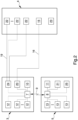
Figure 2 is a block diagram of the system according to the invention in a first working configuration; -
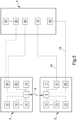
Figure 3 is a block diagram of the system according to the invention in a second working configuration. - With particular reference to these figures, reference numeral 1 globally indicates a piece of equipment for the control of biomedical devices during the extracorporeal circulation.
- The piece of equipment 1 for the control of biomedical devices during the extracorporeal circulation comprises:
- at least one
basic structure 2; - control means 3, 5, 9, 10, 11 of the piece of equipment 1 assembled on the
basic structure 2 and provided with at least one control unit 3 operationally connectable to at least onebiomedical device 4 for the extracorporeal circulation and configured to control the latter. - Advantageously, the control means 3, 5, 9, 10, 11 comprise at least one emergency control unit 5, operationally connectable to the
biomedical device 4 and configured to control the latter as a result of a malfunction of the control unit 3. - This way, if the control unit 3 stops operating properly, the functionality of the
biomedical device 4 is ensured by the emergency control unit 5. - Conveniently, the
basic structure 2 comprises support means 6 of thebiomedical device 4 adapted to fasten the latter to the samebasic structure 2 in a removable manner. - Conveniently, the control means 3, 5, 9, 10, 11 comprise communication means 9 between the control unit 3 and the emergency control unit 5.
- According to the invention, the control unit 3 and the emergency control unit 5 are configured to check the malfunction of the other.
- This way, any malfunction of the control unit 3 is immediately detected by the emergency control unit 5.
- In addition, this device makes it possible to immediately identify any malfunction of the emergency control unit 5 during the correct operation of the control unit 3.
- This way, it is possible to intervene promptly with the repair of the emergency control unit 5 and to prevent the emergency control unit 5 from malfunctioning and therefore being unusable as a result of the malfunction of the control unit 3, putting the patient's safety at risk.
- In particular, the control unit 3 comprises at least one
central unit 7 for the management of the same control unit and configured to check the malfunction of the emergency control unit 5. - Similarly, the emergency control unit 5 comprises at least one
central emergency unit 8 for the control of the same emergency control unit and configured to check the malfunction of the control unit 3. - Therefore, according to the invention, the communication means 9 are operationally connected to the
central unit 7 and to thecentral emergency unit 8 in order to allow these to check the malfunction of the emergency control unit 5 and of the control unit 3 respectively. - Preferably, the
central unit 7 is an electronic device of the type e.g. of a microprocessor, microcontroller, PLC and the like. - Similarly, the
central emergency unit 8 is an electronic device of the type e.g. of a microprocessor, microcontroller, PLC, control unit and the like. - In addition, the communication means 9 are preferably of the type of a low-voltage two-way electronic link for signal exchange.
- Advantageously, the control means 3, 5, 9, 10, 11 comprise signaling means 10, 11 for signaling the malfunction of at least one of either the control unit 3 or the emergency control unit 5.
- Preferably, the control unit 3 comprises at least one
signaling unit 10 configured to notify a user of the malfunction of the emergency control unit 5. - Likewise, the emergency control unit 5 preferably comprises at least one
emergency signaling unit 11 configured to notify a user of the malfunction of the control unit 3. - In addition, preferably, the
signaling unit 10 is operationally connected to thecentral unit 7. - Likewise, the
emergency signaling unit 11 is operationally connected to thecentral emergency unit 8. - Conveniently, the control unit 3 comprises at least one input/
output device 12 configured to check/monitor thebiomedical device 4. - In particular, the input/
output device 12 is of the type selected from the list comprising a keyboard, a screen, a USB socket, a code reader, an electronic switch. - Preferably, the input/
output device 12 is operationally connected to thecentral unit 7. - In addition, the control unit 3 comprises a plurality of input/
output devices 12. In particular, according to the invention, the control unit 3 comprises an input/output device 12 of each type included in the above mentioned list. Conveniently, the emergency control unit 5 comprises at least one emergency input/output device 13 of the type selected from the list comprising a keyboard, a screen, a USB socket, a code reader, an electronic switch. - Preferably, the emergency input/
output device 13 is operationally connected to thecentral emergency unit 8. - Preferably, the control unit 3 comprises a plurality of emergency input/
output devices 13. - In particular, according to the invention, the emergency control unit 5 comprises an emergency input/
output device 13 of each type included in the above mentioned list. - This way, the control unit 3 and the emergency control unit 5 have the same input/output devices for the correct management of the same equipment and of the
biomedical device 4. - Conveniently, the equipment 1 comprises connection means 16, 19 of the
biomedical device 4 to one of either the control unit 3 or the emergency control unit 5. - In particular, the connection means 16, 19 are connectable in a removable manner between at least a first operating configuration, wherein they operationally connect the
biomedical device 4 to the control unit 3, and at least a second operating configuration, wherein they operationally connect thebiomedical device 4 to the emergency control unit 5. - This way, as a result of a malfunction of the control unit 3, the
biomedical device 4 is controlled by the emergency control unit 5, which ensures the correct operation of thebiomedical device 4. - Advantageously, the connection means 16, 19 are operationally connectable to a plurality of
components biomedical device 4. - In particular, the connection means 16, 19 connect, in a removable manner, at least one
component components - This way, the equipment 1 allows ensuring the operation of the
biomedical devices 4 provided with a plurality ofcomponents - The present invention also relates to a system for extracorporeal circulation globally indicated with
reference number 14. - The
system 14 for extracorporeal circulation comprises: - at least one
biomedical device 4 for the extracorporeal circulation; - at least one piece of equipment 1 having one or more of the characteristics of the equipment 1 described above.
- Advantageously, the
biomedical device 4 comprises at least one pumping motor-drivenunit 15 for extracorporeal circulation. - In addition, the connection means 16, 19 comprise at least one connecting
line 16 which operationally connects the motor-drivenunit 15 to the control unit 3 and to the emergency control unit 5 in the first and in the second operating configuration, respectively. - Preferably, the connecting
line 16 can be manually connected/disconnected by a user who, as a result of a malfunction of the control unit 3, disconnects the connectingline 16 from the latter and connects it to the emergency control unit 5. - Furthermore, the connecting
line 16 is of the type of an electronic connection device provided with connectors such as, e.g, an electric cable or the like. Advantageously, the control unit 3 comprises at least onedrive unit 20 of the motor-drivenunit 15 and the emergency control unit 5 comprises at least oneemergency drive unit 21 of the motor-drivenunit 15. - This way, the connecting
line 16 operationally connects the motor-drivenunit 15 to thedrive unit 20 and to theemergency drive unit 21 in the first operating configuration and in the second operating configuration, respectively. - In particular, the
drive unit 20 is operationally connected to thecentral unit 7. Similarly, theemergency drive unit 21 is operationally connected to thecentral emergency unit 8. - Conveniently, the
biomedical device 4 comprises at least onemonitoring unit sensor device 22 selected from the list comprising a flow meter, pressure sensor, level sensor, in-line air detector, venous probe, arterial probe. - In addition, the connection means 16, 19 comprise at least one linking
line 19 which operationally connects thesensor device 22 to the control unit 3 and to the emergency control unit 5 in the first operating configuration and in the second operating configuration, respectively. - Conveniently, the linking
line 19 can be manually connected/disconnected by a user, who, as a result of a malfunction of the control unit 3, disconnects the linkingline 19 from the latter and connects it to the emergency control unit 5. This way, as a result of a malfunction of the control unit 3, thesensor device 22 is controlled by the emergency control unit 5, which uses the data collected by this sensor to ensure the correct extracorporeal circulation. - Preferably, the
sensor device 22 is of the type of a flow meter. - Conveniently, the
monitoring unit sensor devices 22. - Preferably, the
monitoring unit sensor device 22 for each type included in the list comprising a pressure sensor, level sensor, in-line air detector, venous probe, arterial probe. - In addition, preferably, the
monitoring unit sensor devices 22 of the type of pressure sensors. - Advantageously, at least one of the
sensor devices 22 is operationally connected to the control unit 3. - In particular, according to the invention, all the
sensor devices 22 with the exception of the flow meter, are operationally connected in a fixed manner to the control unit 3. - In other words, according to the invention, only the
sensor device 22 of the type of a flow meter can be connected in a removable manner to one of either the control unit 3 or the emergency control unit 5 by interposition of the linkingline 19. On the contrary, theother sensor devices 22 are operationally permanently connected to the control unit 3, i.e. there is no provision for these sensors to be disconnected from the latter. - Further embodiments of the
system 14 cannot however be ruled out wherein the connection means 16, 19 comprise a plurality of linkinglines 19, each adapted to connect arespective sensor device 22 to the control unit 3 and to the emergency control unit 5 in the first operating configuration and in the second operating configuration, respectively. - Conveniently, the
monitoring unit emergency sensor device 23 selected from the list comprising a flow meter, pressure sensor, level sensor, in-line air detector, venous probe, arterial probe. - In addition, the linking
line 19 operationally connects the control unit 3 to thesensor device 22 in the first operating configuration, and operationally connects the emergency control unit 5 to one of either thesensor device 22 or theemergency sensor device 23 in the second operating configuration. - Preferably, the
emergency sensor device 23 is a flow meter. - According to the embodiment of the
system 14 shown in the figures, in the first operating configuration the linkingline 19 operationally connects the control unit 3 to thesensor device 22 and, in the second operating configuration, the linkingline 19 operationally connects theemergency sensor device 23 to the emergency control unit 5. - Further embodiments of the
system 14 cannot however be ruled out wherein, in the first operating configuration, the linkingline 19 operationally connects the control unit 3 to thesensor device 22 and, in the second operating configuration, the linkingline 19 connects the same sensor device to the emergency control unit 5. - In other words, as a result of a malfunction of the control unit 3, the linking
line 19 must be disconnected from the control unit 3 in order to be connected to the emergency control unit 5 and connect the latter to thesensor device 22 previously connected to the control unit 3. - In addition, further embodiments of the
system 14 cannot be ruled out in which themonitoring unit emergency sensor devices 23. For example, embodiments of thesystem 14 cannot be ruled out wherein themonitoring unit emergency sensor device 23 for each type listed above, or wherein themonitoring unit emergency sensor devices 23 in the same number and of the same type as thesensor devices 22. Advantageously, the control unit 3 comprises at least onecheck unit 24 of themonitoring unit - In addition, the emergency control unit 5 comprises at least one
emergency check unit 25 of themonitoring unit - This way, the linking
line 19 operationally connects themonitoring unit drive unit 20 and to theemergency drive unit 21 in the first operating configuration and in the second operating configuration, respectively. - In particular, according to the invention, the
sensor devices 22 other than the flow meter are operationally permanently connected to thecheck unit 24. - It has, in practice, been ascertained that the described invention achieves the intended objects.
- In particular, the emergency control unit ensures the correct operation of the equipment and of the related system even in the event of a malfunction of the control unit.
- In addition, the communication means make it possible to identify in advance any malfunction of the emergency control unit, thus reducing the risk of simultaneous malfunction of the control unit and of the emergency control unit.
Claims (11)
- Equipment (1) for the control of biomedical devices during extracorporeal circulation, comprising:- at least one basic structure (2);- control means (3, 5, 9, 10, 11) assembled on said basic structure (2) and provided with at least one control unit (3) operationally connectable to at least one biomedical device (4) for extracorporeal circulation and configured to control it;wherein said control means (3, 5, 9, 10, 11) comprise at least one emergency control unit (5), operationally connectable to said biomedical device (4) and configured to control the latter following a malfunction of said control unit (3);wherein said control means (3, 5, 9, 10, 11) comprise communication means (9) between said control unit (3) and said emergency control unit (5), said emergency control unit (5) being configured to check the malfunction of said control unit (3) and characterized in that said control unit (3) is configured to check the malfunction of said emergency control unit (5) during the correct operation of said control unit (3).
- Equipment (1) according to claim 1, characterized by the fact that said basic structure (2) comprises support means (6) of said biomedical device (4) adapted to fasten the latter to the same basic structure in a removable manner.
- Equipment (1) according to one or more of the preceding claims, characterized by the fact that said control means (3, 5, 9, 10, 11) comprise at least one input/output device (12) configured to check/monitor said biomedical device (4), said input/output device (12) being of the type selected from the list comprising a keyboard, a screen, a USB socket, a code reader, an electronic switch.
- Equipment (1) according to one or more of the preceding claims, characterized by the fact that said emergency control unit (5) comprises at least one emergency input/output device (13) configured to check/monitor said biomedical device (4), said emergency input/output device (13) being of the type selected from the list comprising a keyboard, a screen, a USB socket, a code reader, an electronic switch.
- Equipment (1) according to one or more of the preceding claims, characterized by the fact that it comprises connection means (16, 19) of said biomedical device (4) to one of either said control unit (3) and said emergency control unit (5), said connection means (16, 19) being connectable in a removable manner between at least a first operating configuration, wherein they operationally connect said biomedical device (4) to said control unit (3), and at least a second operating configuration, wherein they operationally connect said biomedical device (4) to said emergency control unit (5).
- Equipment (1) according to one or more of the preceding claims, characterized by the fact that said connection means (16, 19) are operationally connectable to a plurality of components (15, 22, 23) of said biomedical device (4), said connection means (16, 19) connecting in a removable manner at least one component (15, 22, 23) to said control unit (3) and to said emergency control unit (5) in said first and in said second operating configuration, respectively.
- System (14) for the control of biomedical devices during extracorporeal circulation, comprising:- at least one biomedical device (4) for extracorporeal circulation;- at least one piece of equipment (1) according to one or more of claims 1 to 6.
- System (14) according to claim 7, characterized by the fact that:- said biomedical device (4) comprises at least one pumping motor-driven unit (15) for extracorporeal circulation;- said connection means (16, 19) comprise at least one connecting line (16) which operationally connects said motor-driven unit (15) to said control unit (3) and to said emergency control unit (5) in said first and in said second operating configuration respectively.
- System (14) according to one or more of claims 7 to 8, characterized by the fact that:- said biomedical device (4) comprises at least one monitoring unit (22, 23) of the extracorporeal circulation provided with at least one sensor device (22) selected from the list comprising a flow meter, pressure sensor, level sensor, in-line air detector, venous probe, arterial probe;- said connection means (16, 19) comprise at least one linking line (19) which operationally connects the sensor device (22) to said control unit (3) and to said emergency control unit (5) in said first and in said second operating configuration, respectively.
- System (14) according to claim 9, characterized by the fact that said monitoring unit (22, 23) comprises a plurality of said sensor devices (22).
- System (14) according to claim 9, characterized by the fact that:- said monitoring unit (22, 23) comprises at least one emergency sensor device (23) selected from the list comprising a flow meter, pressure sensor, level sensor, in-line air detector, venous probe, arterial probe;- said linking line (19) operationally connects said control unit (3) to said sensor device (22) in said first operating configuration, and operationally connects said emergency control unit (5) to one of either said sensor device (22) or said emergency sensor device (23) in said second operating configuration.
Applications Claiming Priority (2)
| Application Number | Priority Date | Filing Date | Title |
|---|---|---|---|
| IT102019000021012A IT201900021012A1 (en) | 2019-11-12 | 2019-11-12 | EQUIPMENT FOR CHECKING BIOMEDICAL DEVICES DURING EXTRA-BODY CIRCULATION AND RELATED SYSTEM |
| PCT/IB2020/060654 WO2021094971A1 (en) | 2019-11-12 | 2020-11-12 | Equipment for the control of biomedical devices during extracorporeal circulation and related system |
Publications (2)
| Publication Number | Publication Date |
|---|---|
| EP4058099A1 EP4058099A1 (en) | 2022-09-21 |
| EP4058099B1 true EP4058099B1 (en) | 2024-01-31 |
Family
ID=73038289
Family Applications (1)
| Application Number | Title | Priority Date | Filing Date |
|---|---|---|---|
| EP20821379.3A Active EP4058099B1 (en) | 2019-11-12 | 2020-11-12 | Equipment for the control of biomedical devices during extracorporeal circulation and related system |
Country Status (6)
| Country | Link |
|---|---|
| US (1) | US20220387688A1 (en) |
| EP (1) | EP4058099B1 (en) |
| JP (1) | JP2023502175A (en) |
| CN (1) | CN114728119A (en) |
| IT (1) | IT201900021012A1 (en) |
| WO (1) | WO2021094971A1 (en) |
Families Citing this family (2)
| Publication number | Priority date | Publication date | Assignee | Title |
|---|---|---|---|---|
| USD1058818S1 (en) * | 2022-02-17 | 2025-01-21 | Eurosets S.R.L. | Biomedical device support |
| USD1058819S1 (en) * | 2022-02-17 | 2025-01-21 | Eurosets S.R.L. | Biomedical device support |
Family Cites Families (10)
| Publication number | Priority date | Publication date | Assignee | Title |
|---|---|---|---|---|
| US4823256A (en) * | 1984-06-22 | 1989-04-18 | American Telephone And Telegraph Company, At&T Bell Laboratories | Reconfigurable dual processor system |
| US6808508B1 (en) * | 2000-09-13 | 2004-10-26 | Cardiacassist, Inc. | Method and system for closed chest blood flow support |
| US6868309B1 (en) * | 2001-09-24 | 2005-03-15 | Aksys, Ltd. | Dialysis machine with symmetric multi-processing (SMP) control system and method of operation |
| US7198751B2 (en) * | 2003-01-14 | 2007-04-03 | Medtronic, Inc. | Disposable, integrated, extracorporeal blood circuit |
| US7805978B2 (en) * | 2006-10-24 | 2010-10-05 | Zevex, Inc. | Method for making and using an air bubble detector |
| JP5628186B2 (en) * | 2008-10-30 | 2014-11-19 | フレセニウス メディカル ケア ホールディングス インコーポレーテッド | Modular portable dialysis system |
| WO2014037971A1 (en) * | 2012-09-05 | 2014-03-13 | テルモ株式会社 | Extracorporeal circulation device and control method therefor |
| DE102014102732A1 (en) * | 2014-02-28 | 2015-09-03 | B. Braun Avitum Ag | System and method for detecting a venous needle disconnection |
| DE102014102730A1 (en) * | 2014-02-28 | 2015-09-03 | B. Braun Avitum Ag | Device and method for detecting an error in the extracorporeal blood circulation |
| DE102018106906A1 (en) * | 2018-03-22 | 2019-09-26 | Fresenius Medical Care Deutschland Gmbh | Medical device |
-
2019
- 2019-11-12 IT IT102019000021012A patent/IT201900021012A1/en unknown
-
2020
- 2020-11-12 JP JP2022553230A patent/JP2023502175A/en active Pending
- 2020-11-12 CN CN202080078672.8A patent/CN114728119A/en active Pending
- 2020-11-12 WO PCT/IB2020/060654 patent/WO2021094971A1/en not_active Ceased
- 2020-11-12 US US17/775,989 patent/US20220387688A1/en not_active Abandoned
- 2020-11-12 EP EP20821379.3A patent/EP4058099B1/en active Active
Also Published As
| Publication number | Publication date |
|---|---|
| EP4058099A1 (en) | 2022-09-21 |
| US20220387688A1 (en) | 2022-12-08 |
| JP2023502175A (en) | 2023-01-20 |
| WO2021094971A1 (en) | 2021-05-20 |
| IT201900021012A1 (en) | 2021-05-12 |
| CN114728119A (en) | 2022-07-08 |
Similar Documents
| Publication | Publication Date | Title |
|---|---|---|
| US20240112784A1 (en) | Monitoring system for a dialysis machine | |
| EP2599510B1 (en) | Controller for a blood pump system | |
| US10391224B2 (en) | Pressure sensing extracorporeal circulation device | |
| KR101643676B1 (en) | Identifying a self-powered device connected to a medical device | |
| US20220387688A1 (en) | Equipment for the control of biomedical devices during extracorporeal circulation and related system | |
| EP0997157B1 (en) | Blood treatment device | |
| AU2009263944B2 (en) | A user interface for monitoring the status of medical machines | |
| US20080221495A1 (en) | Blood pump system user interface alarm management | |
| EP3015123B1 (en) | Acute renal replacement therapy apparatus | |
| EP1061971B1 (en) | Apparatus for dialysis with blood-warmer | |
| CN107073188B (en) | System including a plurality of medical devices and method for its operation | |
| JP2006346333A (en) | Management system for hemodialysis unit | |
| JP5506102B2 (en) | Blood purification system | |
| CN213205942U (en) | Peristaltic pump and its control circuit, blood purification equipment | |
| CN117838961A (en) | Blood purification device and storage medium | |
| JP6324797B2 (en) | Extracorporeal circulation device and control method for extracorporeal circulation device | |
| US12064539B2 (en) | Medical device | |
| CN210933250U (en) | Anesthesia machine and dual monitoring device of air flue pressure thereof | |
| CN113230473A (en) | Control device of hemodialysis equipment | |
| JP2019069149A (en) | Dialysis device, control device, channel structure, channel forming method, control program, and recording medium | |
| WO2018230632A1 (en) | Blood purification system | |
| US20210125712A1 (en) | Maintenance notification for medical devices | |
| Wang | 43. Evidence-based practice supports mid-run intradialytic blood pressure assessment over of close BP monitoring in haemodialysis patients | |
| JP2004063142A (en) | Connector disconnection detection method and device, and medical device provided with connector disconnection detection means | |
| US20190036619A1 (en) | Medical device with a communications interface configured for protection of patients and operators |
Legal Events
| Date | Code | Title | Description |
|---|---|---|---|
| STAA | Information on the status of an ep patent application or granted ep patent |
Free format text: STATUS: UNKNOWN |
|
| STAA | Information on the status of an ep patent application or granted ep patent |
Free format text: STATUS: THE INTERNATIONAL PUBLICATION HAS BEEN MADE |
|
| PUAI | Public reference made under article 153(3) epc to a published international application that has entered the european phase |
Free format text: ORIGINAL CODE: 0009012 |
|
| STAA | Information on the status of an ep patent application or granted ep patent |
Free format text: STATUS: REQUEST FOR EXAMINATION WAS MADE |
|
| 17P | Request for examination filed |
Effective date: 20220608 |
|
| AK | Designated contracting states |
Kind code of ref document: A1 Designated state(s): AL AT BE BG CH CY CZ DE DK EE ES FI FR GB GR HR HU IE IS IT LI LT LU LV MC MK MT NL NO PL PT RO RS SE SI SK SM TR |
|
| DAV | Request for validation of the european patent (deleted) | ||
| DAX | Request for extension of the european patent (deleted) | ||
| GRAP | Despatch of communication of intention to grant a patent |
Free format text: ORIGINAL CODE: EPIDOSNIGR1 |
|
| STAA | Information on the status of an ep patent application or granted ep patent |
Free format text: STATUS: GRANT OF PATENT IS INTENDED |
|
| INTG | Intention to grant announced |
Effective date: 20230908 |
|
| GRAS | Grant fee paid |
Free format text: ORIGINAL CODE: EPIDOSNIGR3 |
|
| GRAA | (expected) grant |
Free format text: ORIGINAL CODE: 0009210 |
|
| STAA | Information on the status of an ep patent application or granted ep patent |
Free format text: STATUS: THE PATENT HAS BEEN GRANTED |
|
| AK | Designated contracting states |
Kind code of ref document: B1 Designated state(s): AL AT BE BG CH CY CZ DE DK EE ES FI FR GB GR HR HU IE IS IT LI LT LU LV MC MK MT NL NO PL PT RO RS SE SI SK SM TR |
|
| REG | Reference to a national code |
Ref country code: GB Ref legal event code: FG4D Ref country code: CH Ref legal event code: EP |
|
| REG | Reference to a national code |
Ref country code: DE Ref legal event code: R096 Ref document number: 602020025075 Country of ref document: DE |
|
| REG | Reference to a national code |
Ref country code: IE Ref legal event code: FG4D |
|
| P01 | Opt-out of the competence of the unified patent court (upc) registered |
Effective date: 20240214 |
|
| REG | Reference to a national code |
Ref country code: LT Ref legal event code: MG9D |
|
| REG | Reference to a national code |
Ref country code: NL Ref legal event code: MP Effective date: 20240131 |
|
| PG25 | Lapsed in a contracting state [announced via postgrant information from national office to epo] |
Ref country code: IS Free format text: LAPSE BECAUSE OF FAILURE TO SUBMIT A TRANSLATION OF THE DESCRIPTION OR TO PAY THE FEE WITHIN THE PRESCRIBED TIME-LIMIT Effective date: 20240531 |
|
| PG25 | Lapsed in a contracting state [announced via postgrant information from national office to epo] |
Ref country code: LT Free format text: LAPSE BECAUSE OF FAILURE TO SUBMIT A TRANSLATION OF THE DESCRIPTION OR TO PAY THE FEE WITHIN THE PRESCRIBED TIME-LIMIT Effective date: 20240131 |
|
| PG25 | Lapsed in a contracting state [announced via postgrant information from national office to epo] |
Ref country code: GR Free format text: LAPSE BECAUSE OF FAILURE TO SUBMIT A TRANSLATION OF THE DESCRIPTION OR TO PAY THE FEE WITHIN THE PRESCRIBED TIME-LIMIT Effective date: 20240501 |
|
| REG | Reference to a national code |
Ref country code: AT Ref legal event code: MK05 Ref document number: 1653423 Country of ref document: AT Kind code of ref document: T Effective date: 20240131 |
|
| PG25 | Lapsed in a contracting state [announced via postgrant information from national office to epo] |
Ref country code: RS Free format text: LAPSE BECAUSE OF FAILURE TO SUBMIT A TRANSLATION OF THE DESCRIPTION OR TO PAY THE FEE WITHIN THE PRESCRIBED TIME-LIMIT Effective date: 20240430 Ref country code: HR Free format text: LAPSE BECAUSE OF FAILURE TO SUBMIT A TRANSLATION OF THE DESCRIPTION OR TO PAY THE FEE WITHIN THE PRESCRIBED TIME-LIMIT Effective date: 20240131 Ref country code: NL Free format text: LAPSE BECAUSE OF FAILURE TO SUBMIT A TRANSLATION OF THE DESCRIPTION OR TO PAY THE FEE WITHIN THE PRESCRIBED TIME-LIMIT Effective date: 20240131 |
|
| PG25 | Lapsed in a contracting state [announced via postgrant information from national office to epo] |
Ref country code: ES Free format text: LAPSE BECAUSE OF FAILURE TO SUBMIT A TRANSLATION OF THE DESCRIPTION OR TO PAY THE FEE WITHIN THE PRESCRIBED TIME-LIMIT Effective date: 20240131 |
|
| PG25 | Lapsed in a contracting state [announced via postgrant information from national office to epo] |
Ref country code: AT Free format text: LAPSE BECAUSE OF FAILURE TO SUBMIT A TRANSLATION OF THE DESCRIPTION OR TO PAY THE FEE WITHIN THE PRESCRIBED TIME-LIMIT Effective date: 20240131 |
|
| PG25 | Lapsed in a contracting state [announced via postgrant information from national office to epo] |
Ref country code: RS Free format text: LAPSE BECAUSE OF FAILURE TO SUBMIT A TRANSLATION OF THE DESCRIPTION OR TO PAY THE FEE WITHIN THE PRESCRIBED TIME-LIMIT Effective date: 20240430 Ref country code: NO Free format text: LAPSE BECAUSE OF FAILURE TO SUBMIT A TRANSLATION OF THE DESCRIPTION OR TO PAY THE FEE WITHIN THE PRESCRIBED TIME-LIMIT Effective date: 20240430 Ref country code: NL Free format text: LAPSE BECAUSE OF FAILURE TO SUBMIT A TRANSLATION OF THE DESCRIPTION OR TO PAY THE FEE WITHIN THE PRESCRIBED TIME-LIMIT Effective date: 20240131 Ref country code: LT Free format text: LAPSE BECAUSE OF FAILURE TO SUBMIT A TRANSLATION OF THE DESCRIPTION OR TO PAY THE FEE WITHIN THE PRESCRIBED TIME-LIMIT Effective date: 20240131 Ref country code: IS Free format text: LAPSE BECAUSE OF FAILURE TO SUBMIT A TRANSLATION OF THE DESCRIPTION OR TO PAY THE FEE WITHIN THE PRESCRIBED TIME-LIMIT Effective date: 20240531 Ref country code: HR Free format text: LAPSE BECAUSE OF FAILURE TO SUBMIT A TRANSLATION OF THE DESCRIPTION OR TO PAY THE FEE WITHIN THE PRESCRIBED TIME-LIMIT Effective date: 20240131 Ref country code: GR Free format text: LAPSE BECAUSE OF FAILURE TO SUBMIT A TRANSLATION OF THE DESCRIPTION OR TO PAY THE FEE WITHIN THE PRESCRIBED TIME-LIMIT Effective date: 20240501 Ref country code: FI Free format text: LAPSE BECAUSE OF FAILURE TO SUBMIT A TRANSLATION OF THE DESCRIPTION OR TO PAY THE FEE WITHIN THE PRESCRIBED TIME-LIMIT Effective date: 20240131 Ref country code: ES Free format text: LAPSE BECAUSE OF FAILURE TO SUBMIT A TRANSLATION OF THE DESCRIPTION OR TO PAY THE FEE WITHIN THE PRESCRIBED TIME-LIMIT Effective date: 20240131 Ref country code: BG Free format text: LAPSE BECAUSE OF FAILURE TO SUBMIT A TRANSLATION OF THE DESCRIPTION OR TO PAY THE FEE WITHIN THE PRESCRIBED TIME-LIMIT Effective date: 20240131 Ref country code: AT Free format text: LAPSE BECAUSE OF FAILURE TO SUBMIT A TRANSLATION OF THE DESCRIPTION OR TO PAY THE FEE WITHIN THE PRESCRIBED TIME-LIMIT Effective date: 20240131 |
|
| PG25 | Lapsed in a contracting state [announced via postgrant information from national office to epo] |
Ref country code: PL Free format text: LAPSE BECAUSE OF FAILURE TO SUBMIT A TRANSLATION OF THE DESCRIPTION OR TO PAY THE FEE WITHIN THE PRESCRIBED TIME-LIMIT Effective date: 20240131 Ref country code: PT Free format text: LAPSE BECAUSE OF FAILURE TO SUBMIT A TRANSLATION OF THE DESCRIPTION OR TO PAY THE FEE WITHIN THE PRESCRIBED TIME-LIMIT Effective date: 20240531 |
|
| PG25 | Lapsed in a contracting state [announced via postgrant information from national office to epo] |
Ref country code: SE Free format text: LAPSE BECAUSE OF FAILURE TO SUBMIT A TRANSLATION OF THE DESCRIPTION OR TO PAY THE FEE WITHIN THE PRESCRIBED TIME-LIMIT Effective date: 20240131 Ref country code: PT Free format text: LAPSE BECAUSE OF FAILURE TO SUBMIT A TRANSLATION OF THE DESCRIPTION OR TO PAY THE FEE WITHIN THE PRESCRIBED TIME-LIMIT Effective date: 20240531 Ref country code: PL Free format text: LAPSE BECAUSE OF FAILURE TO SUBMIT A TRANSLATION OF THE DESCRIPTION OR TO PAY THE FEE WITHIN THE PRESCRIBED TIME-LIMIT Effective date: 20240131 Ref country code: LV Free format text: LAPSE BECAUSE OF FAILURE TO SUBMIT A TRANSLATION OF THE DESCRIPTION OR TO PAY THE FEE WITHIN THE PRESCRIBED TIME-LIMIT Effective date: 20240131 |
|
| PG25 | Lapsed in a contracting state [announced via postgrant information from national office to epo] |
Ref country code: DK Free format text: LAPSE BECAUSE OF FAILURE TO SUBMIT A TRANSLATION OF THE DESCRIPTION OR TO PAY THE FEE WITHIN THE PRESCRIBED TIME-LIMIT Effective date: 20240131 |
|
| PG25 | Lapsed in a contracting state [announced via postgrant information from national office to epo] |
Ref country code: SM Free format text: LAPSE BECAUSE OF FAILURE TO SUBMIT A TRANSLATION OF THE DESCRIPTION OR TO PAY THE FEE WITHIN THE PRESCRIBED TIME-LIMIT Effective date: 20240131 |
|
| PG25 | Lapsed in a contracting state [announced via postgrant information from national office to epo] |
Ref country code: EE Free format text: LAPSE BECAUSE OF FAILURE TO SUBMIT A TRANSLATION OF THE DESCRIPTION OR TO PAY THE FEE WITHIN THE PRESCRIBED TIME-LIMIT Effective date: 20240131 Ref country code: CZ Free format text: LAPSE BECAUSE OF FAILURE TO SUBMIT A TRANSLATION OF THE DESCRIPTION OR TO PAY THE FEE WITHIN THE PRESCRIBED TIME-LIMIT Effective date: 20240131 |
|
| PG25 | Lapsed in a contracting state [announced via postgrant information from national office to epo] |
Ref country code: SK Free format text: LAPSE BECAUSE OF FAILURE TO SUBMIT A TRANSLATION OF THE DESCRIPTION OR TO PAY THE FEE WITHIN THE PRESCRIBED TIME-LIMIT Effective date: 20240131 |
|
| PG25 | Lapsed in a contracting state [announced via postgrant information from national office to epo] |
Ref country code: SM Free format text: LAPSE BECAUSE OF FAILURE TO SUBMIT A TRANSLATION OF THE DESCRIPTION OR TO PAY THE FEE WITHIN THE PRESCRIBED TIME-LIMIT Effective date: 20240131 Ref country code: SK Free format text: LAPSE BECAUSE OF FAILURE TO SUBMIT A TRANSLATION OF THE DESCRIPTION OR TO PAY THE FEE WITHIN THE PRESCRIBED TIME-LIMIT Effective date: 20240131 Ref country code: RO Free format text: LAPSE BECAUSE OF FAILURE TO SUBMIT A TRANSLATION OF THE DESCRIPTION OR TO PAY THE FEE WITHIN THE PRESCRIBED TIME-LIMIT Effective date: 20240131 Ref country code: EE Free format text: LAPSE BECAUSE OF FAILURE TO SUBMIT A TRANSLATION OF THE DESCRIPTION OR TO PAY THE FEE WITHIN THE PRESCRIBED TIME-LIMIT Effective date: 20240131 Ref country code: DK Free format text: LAPSE BECAUSE OF FAILURE TO SUBMIT A TRANSLATION OF THE DESCRIPTION OR TO PAY THE FEE WITHIN THE PRESCRIBED TIME-LIMIT Effective date: 20240131 Ref country code: CZ Free format text: LAPSE BECAUSE OF FAILURE TO SUBMIT A TRANSLATION OF THE DESCRIPTION OR TO PAY THE FEE WITHIN THE PRESCRIBED TIME-LIMIT Effective date: 20240131 |
|
| REG | Reference to a national code |
Ref country code: DE Ref legal event code: R097 Ref document number: 602020025075 Country of ref document: DE |
|
| PLBE | No opposition filed within time limit |
Free format text: ORIGINAL CODE: 0009261 |
|
| STAA | Information on the status of an ep patent application or granted ep patent |
Free format text: STATUS: NO OPPOSITION FILED WITHIN TIME LIMIT |
|
| 26N | No opposition filed |
Effective date: 20241101 |
|
| PG25 | Lapsed in a contracting state [announced via postgrant information from national office to epo] |
Ref country code: SI Free format text: LAPSE BECAUSE OF FAILURE TO SUBMIT A TRANSLATION OF THE DESCRIPTION OR TO PAY THE FEE WITHIN THE PRESCRIBED TIME-LIMIT Effective date: 20240131 |
|
| REG | Reference to a national code |
Ref country code: CH Ref legal event code: PL |
|
| PG25 | Lapsed in a contracting state [announced via postgrant information from national office to epo] |
Ref country code: MC Free format text: LAPSE BECAUSE OF FAILURE TO SUBMIT A TRANSLATION OF THE DESCRIPTION OR TO PAY THE FEE WITHIN THE PRESCRIBED TIME-LIMIT Effective date: 20240131 |
|
| PG25 | Lapsed in a contracting state [announced via postgrant information from national office to epo] |
Ref country code: LU Free format text: LAPSE BECAUSE OF NON-PAYMENT OF DUE FEES Effective date: 20241112 |
|
| REG | Reference to a national code |
Ref country code: CH Ref legal event code: PL |
|
| PG25 | Lapsed in a contracting state [announced via postgrant information from national office to epo] |
Ref country code: CH Free format text: LAPSE BECAUSE OF NON-PAYMENT OF DUE FEES Effective date: 20241130 |
|
| PG25 | Lapsed in a contracting state [announced via postgrant information from national office to epo] |
Ref country code: IE Free format text: LAPSE BECAUSE OF NON-PAYMENT OF DUE FEES Effective date: 20241112 |
|
| PGFP | Annual fee paid to national office [announced via postgrant information from national office to epo] |
Ref country code: DE Payment date: 20251128 Year of fee payment: 6 |
|
| PGFP | Annual fee paid to national office [announced via postgrant information from national office to epo] |
Ref country code: GB Payment date: 20251127 Year of fee payment: 6 |
|
| PGFP | Annual fee paid to national office [announced via postgrant information from national office to epo] |
Ref country code: IT Payment date: 20251119 Year of fee payment: 6 |
|
| PGFP | Annual fee paid to national office [announced via postgrant information from national office to epo] |
Ref country code: FR Payment date: 20251125 Year of fee payment: 6 |
|
| PGFP | Annual fee paid to national office [announced via postgrant information from national office to epo] |
Ref country code: BE Payment date: 20251127 Year of fee payment: 6 |
|
| PG25 | Lapsed in a contracting state [announced via postgrant information from national office to epo] |
Ref country code: HU Free format text: LAPSE BECAUSE OF FAILURE TO SUBMIT A TRANSLATION OF THE DESCRIPTION OR TO PAY THE FEE WITHIN THE PRESCRIBED TIME-LIMIT; INVALID AB INITIO Effective date: 20201112 |
|
| PG25 | Lapsed in a contracting state [announced via postgrant information from national office to epo] |
Ref country code: CY Free format text: LAPSE BECAUSE OF FAILURE TO SUBMIT A TRANSLATION OF THE DESCRIPTION OR TO PAY THE FEE WITHIN THE PRESCRIBED TIME-LIMIT; INVALID AB INITIO Effective date: 20201112 |