EP4057780A1 - Method for estimating the condition of emergency lighting devices - Google Patents
Method for estimating the condition of emergency lighting devices Download PDFInfo
- Publication number
- EP4057780A1 EP4057780A1 EP21161777.4A EP21161777A EP4057780A1 EP 4057780 A1 EP4057780 A1 EP 4057780A1 EP 21161777 A EP21161777 A EP 21161777A EP 4057780 A1 EP4057780 A1 EP 4057780A1
- Authority
- EP
- European Patent Office
- Prior art keywords
- operating
- device information
- converter
- malfunction
- operating condition
- Prior art date
- Legal status (The legal status is an assumption and is not a legal conclusion. Google has not performed a legal analysis and makes no representation as to the accuracy of the status listed.)
- Granted
Links
Images



Classifications
-
- H—ELECTRICITY
- H05—ELECTRIC TECHNIQUES NOT OTHERWISE PROVIDED FOR
- H05B—ELECTRIC HEATING; ELECTRIC LIGHT SOURCES NOT OTHERWISE PROVIDED FOR; CIRCUIT ARRANGEMENTS FOR ELECTRIC LIGHT SOURCES, IN GENERAL
- H05B47/00—Circuit arrangements for operating light sources in general, i.e. where the type of light source is not relevant
- H05B47/20—Responsive to malfunctions or to light source life; for protection
- H05B47/21—Responsive to malfunctions or to light source life; for protection of two or more light sources connected in parallel
- H05B47/22—Responsive to malfunctions or to light source life; for protection of two or more light sources connected in parallel with communication between the lamps and a central unit
-
- H—ELECTRICITY
- H05—ELECTRIC TECHNIQUES NOT OTHERWISE PROVIDED FOR
- H05B—ELECTRIC HEATING; ELECTRIC LIGHT SOURCES NOT OTHERWISE PROVIDED FOR; CIRCUIT ARRANGEMENTS FOR ELECTRIC LIGHT SOURCES, IN GENERAL
- H05B47/00—Circuit arrangements for operating light sources in general, i.e. where the type of light source is not relevant
- H05B47/10—Controlling the light source
- H05B47/175—Controlling the light source by remote control
- H05B47/19—Controlling the light source by remote control via wireless transmission
-
- H—ELECTRICITY
- H02—GENERATION; CONVERSION OR DISTRIBUTION OF ELECTRIC POWER
- H02J—ELECTRIC POWER NETWORKS; CIRCUIT ARRANGEMENTS OR SYSTEMS FOR SUPPLYING OR DISTRIBUTING ELECTRIC POWER; SYSTEMS FOR STORING ELECTRIC ENERGY
- H02J9/00—Circuit arrangements for emergency or stand-by power supply, e.g. for emergency lighting
- H02J9/04—Circuit arrangements for emergency or stand-by power supply, e.g. for emergency lighting in which the distribution system is disconnected from the normal source and connected to a standby source
- H02J9/06—Circuit arrangements for emergency or stand-by power supply, e.g. for emergency lighting in which the distribution system is disconnected from the normal source and connected to a standby source with automatic change-over, e.g. UPS systems
- H02J9/062—Circuit arrangements for emergency or stand-by power supply, e.g. for emergency lighting in which the distribution system is disconnected from the normal source and connected to a standby source with automatic change-over, e.g. UPS systems for AC powered loads
- H02J9/065—Circuit arrangements for emergency or stand-by power supply, e.g. for emergency lighting in which the distribution system is disconnected from the normal source and connected to a standby source with automatic change-over, e.g. UPS systems for AC powered loads for lighting purposes
-
- H—ELECTRICITY
- H05—ELECTRIC TECHNIQUES NOT OTHERWISE PROVIDED FOR
- H05B—ELECTRIC HEATING; ELECTRIC LIGHT SOURCES NOT OTHERWISE PROVIDED FOR; CIRCUIT ARRANGEMENTS FOR ELECTRIC LIGHT SOURCES, IN GENERAL
- H05B47/00—Circuit arrangements for operating light sources in general, i.e. where the type of light source is not relevant
- H05B47/10—Controlling the light source
- H05B47/17—Operational modes, e.g. switching from manual to automatic mode or prohibiting specific operations
- H05B47/172—Emergency operational modes
-
- H—ELECTRICITY
- H05—ELECTRIC TECHNIQUES NOT OTHERWISE PROVIDED FOR
- H05B—ELECTRIC HEATING; ELECTRIC LIGHT SOURCES NOT OTHERWISE PROVIDED FOR; CIRCUIT ARRANGEMENTS FOR ELECTRIC LIGHT SOURCES, IN GENERAL
- H05B47/00—Circuit arrangements for operating light sources in general, i.e. where the type of light source is not relevant
- H05B47/10—Controlling the light source
- H05B47/175—Controlling the light source by remote control
- H05B47/18—Controlling the light source by remote control via data-bus transmission
- H05B47/183—Controlling the light source by remote control via data-bus transmission using digital addressable lighting interface [DALI] communication protocols
-
- H—ELECTRICITY
- H05—ELECTRIC TECHNIQUES NOT OTHERWISE PROVIDED FOR
- H05B—ELECTRIC HEATING; ELECTRIC LIGHT SOURCES NOT OTHERWISE PROVIDED FOR; CIRCUIT ARRANGEMENTS FOR ELECTRIC LIGHT SOURCES, IN GENERAL
- H05B47/00—Circuit arrangements for operating light sources in general, i.e. where the type of light source is not relevant
- H05B47/10—Controlling the light source
- H05B47/175—Controlling the light source by remote control
Definitions
- the invention relates to a lighting system and a method, with which the technical functioning and operability of components of the lighting system is monitored. More specifically, the invention relates to an emergency lighting system, in which status and functionality of emergency lighting devices is estimated.
- converter devices In emergency lighting systems, converter devices (converters, ballasts, driver devices) are used for providing a supply voltage and/or current to an emergency light for a predetermined time in case mains supply fails.
- the voltage supply is maintained in case of a mains supply failure for a rated service time using energy stored in an energy storage device such as a rechargeable battery.
- the rated service time defines a battery discharge duration during which time the emergency converter is required to drive the emergency light with a predetermined drive current.
- the functionality of the emergency lighting system has to be tested at predefined intervals by performing functional tests, wherein the results have to be protocolled. Such tests can be carried out automatically with some DALI lighting systems.
- EP 3 391 713 A1 discloses an emergency lighting system, in which the tests are carried out autonomously by the emergency lighting devices and, if necessary, protocol data of the test stored in the emergency lighting device are read out by a control device.
- protocol data are not suitable to detect developing problems, to determine causes of failure or to estimate remaining lifetime.
- the lighting system comprises at least one converter device and a control device configured to interpret and recognize failure patterns or other problems associated with the operation of the converter device or its peripheral components. More specifically, the at least one converter device is configured to provide a supply voltage and/or current to an illuminant, to detect an operating status and/or an operating condition of the at least one converter device and to store device information indicating the detected operating status and/or the detected condition and the control device is configured to receive the device information, to predict a malfunction of the at least one converter device based on the device information and/or to determine a malfunction of the at least one converter device and at least one operating condition causal to the determined malfunction based on the device information.
- the predicted malfunction indicates time and/or type of the malfunction and the at least one operating condition can be an operating condition detected by the converter device or another operating condition assigned to the determined malfunction.
- the lighting system can comprise a plurality of the converter devices, wherein the prediction of the malfunction and determination of operating condition can be based on device information obtained from the plurality of the converter devices.
- the at least one converter device can be configured to detect the operating status and/or the operating condition periodically and/or at predetermined events and to store the device information indicating detection time of the operating status and/or the operating condition.
- the device information can be transmitted from the at least one converter device to the control device via a wireless network, a bus system, in particular, a DALI-bus, or Power-line communication (PLC).
- a wireless network e.g., a Wi-Fi network
- a bus system e.g., a Wi-Fi network
- PLC Power-line communication
- the at least one converter device can comprise a wired or wireless interface configured to output the device information.
- the device information can be read out even if the network or the bus system is offline or the at least one converter device is disconnected from the network or the bus system.
- the wireless interface can be an NFC reader/writer (transponder) configured to store the device information so that the device information can be read out even if the converter device is not operating or is defective.
- the control device or a mobile reading device connectable to the control device reads out the device information stored in NFC reader/writer.
- the control device can be configured to request the device information from the at least one converter device periodically and/or at predetermined events, the period for request the device information can be longer than the period for detecting operating statuses and conditions.
- control device can be configured to predict the malfunction and/or to determine the at least one operating condition using a table or a machine learned model.
- the table and the machine learned model assign different operating statuses and/or different operating conditions or different sequences of operating statuses and/or operating conditions to one of a plurality of classes, wherein each class corresponds to a predetermined malfunction or a predetermined operating condition.
- the at least one converter device can be an emergency converter configured to provide a supply voltage and/or current to an emergency light using energy stored in an energy storage device, wherein the operating status includes/indicates at least one of a test operation of the emergency light, a result of the test operation (e.g., determined error), the charge process and discharge process of the energy storage device, the operating condition includes at least one of temperature of the energy storage device, charging duration, discharge duration and number of charge cycles and the control device is configured to predict, based on the device information, when the energy storage device needs replacement before failure.
- the device information can be transmitted from the emergency converter to the control device during test, in which the functionality of the emergency lighting system is tested as described above, or after the test is completed.
- the method for estimating the condition of components of a lighting system comprises the steps of:
- the operating status and/or the operating condition can be detected periodically and/or at predetermined events, wherein in the storage step, the device information indicating detection time of the operating status and/or the operating condition is stored.
- the device information can be transmitted from the at least one converter device to the control device via a DALI-bus or PLC using a PLC-interface connected to the power line in the control device and the converter device (component).
- the transferring step can be performed wirelessly, for example, based on Bluetooth or another wireless communication protocol.
- the transferring step is performed periodically and/or at predetermined events.
- the device information can be stored in NFC reader/writer - more precisely in the EEPROM of the NFC-chip, wherein in the transferring step, the device information stored in NFC reader/writer is read out by the control device or a storage device connectable to the control device.
- the malfunction can be predicted and/or the at least one operating condition can be determined using a table or a machine learned model.
- the table and the machine learned model assign different operating statuses and/or different operating conditions or different sequences of operating statuses and/or operating conditions to one of a plurality of classes, wherein each class corresponds to a predetermined malfunction or a predetermined operating condition.
- the converter device can be an emergency converter configured to provide a supply voltage and/or current to an emergency light using energy stored in an energy storage device, wherein the operating status includes at least one of a test operation of the emergency light, a result of test operation, the charge process and discharge process of the energy storage device, the operating condition includes at least one of a temperature of the energy storage device, charging duration, discharge duration and number of charge cycles and the method further comprises the step of predicting, by the control device, when the energy storage device needs replacement before failure based on the device information.
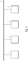
- FIG. 1 shows a DALI lighting system according to a first embodiment of the present invention.
- the DALI lighting system shown in FIG. 1 comprises a controlling device 1, emergency lighting devices 2..4 and a DALI-Bus 5, which connects the controlling device 1 and the emergency lighting devices 2..4.
- additional devices may be comprised by the DALI lighting system.
- the controlling device 1 performs automatic DALI scanning for device changes and automatic DALI short addressing. In this way, the controlling device 1 detects the emergency lighting devices 2..4 connected to the DALI-Bus 5 based on their production numbers and assigns an address to each of the emergency lighting devices 2..4. Further, the controlling device 1 determines the device types (luminaire and others, if any), stores the addresses and associates the device type information to each address, configures the DALI devices based on stored or received configuration information, controls test operations of the emergency lighting devices 2..4 (a function test and an operational duration test), receives device information of the emergency lighting devices 2..4 and estimates the condition of the emergency lighting devices 2..4 based on the device information.
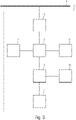
- the controlling device 1 comprises an interface 6 for connecting the controlling device 1 to the DALI-bus 5, a controlling means 7, a storage means 8 (nonvolatile memory) for storing the information described above and an output means 9 configured to output the test results (protocol data) and the results of the estimation performed by the controlling means 7.
- the output means 9 can be a display, a printer, a graphical user interface or a transmitter that transmits the results to a mobile device, such as a tablet, laptop or smart phone.
- FIG. 3 shows the structure of the emergency lighting device 2, wherein the emergency lighting devices 3 and 4 are structured in the same way.
- the emergency lighting device 2 comprises an interface 10 for connecting the emergency lighting device 2 to the DALI-bus 5, a controlling means 11, a storage means 12 (nonvolatile memory) for storing device information, a rechargeable battery 13, a sensor 14 for detecting the temperature of the rechargeable battery 13, an emergency light 14 (e.g. LED or fluorescent lamp), a converter 15 configured to provide a supply voltage and/or current to the emergency light 14 using mains power (not shown) or energy of the rechargeable battery 13 and a charging unit (not shown) for charging the rechargeable battery 13.
- mains power not shown
- energy of the rechargeable battery 13 e.g. LED or fluorescent lamp
- the interface 10, the controlling means 11, the storage means 12 and the converter 15 form an emergency converter, which can be housed in a separate enclosure.
- the controlling means 11 controls the converter 15 to provide the supply voltage and/or current to the emergency light 14 using the energy of the rechargeable battery 13, when power failure or a test mode is detected by the controlling means 11.
- the controlling means 7 and/or the controlling means 11 can be a microcontroller or an Application-Specific Integrated Circuit (ASIC).
- ASIC Application-Specific Integrated Circuit
- the controlling means 11 stores, in the storage means 12, information on the result of each test (successful or failed), the number of tests carried out, test duration, number of charge cycles, total operating time of the emergency light 14 and/or the emergency lighting device 2, total operating time in the test mode and/or the battery mode, maximum temperature of the rechargeable battery 13 detected by the sensor 14, average temperature and a violation of a limit value (max and/or min) of the temperature, the battery voltage, the mains voltage, the drive current and the supply voltage and/or current of the emergency light 14 along with date and time of measurement or the actual counter reading of an operating hours counter.
- information unrelated to testing events is also stored, wherein information about the temperature of the rechargeable battery 13, the battery voltage, the mains voltage, the drive current and the supply voltage is collected continually and independently of tests.
- the time interval for measuring can be set individually based on the temporal changes of the measurement. For example, the temperature can be measured once a minute.
- environmental conditions like humidity and/or temperature may be obtained and stored. The data may be stored during normal operation and in an emergency mode.
- Each emergency lighting device 2..4 collects such device information and transmits the stored device information to the controlling device 1 via the DALI-bus 5 periodically (e.g. once a week).
- the controlling device 1 can be configured to request the device information or part thereof using memory bank commands of DALI.
- the controlling device 1 stores the received device information, determines, for each emergency lighting device 2..4, a malfunction of the emergency lighting device 2..4 (e.g. function test fail, duration test fail, defective emergency light 14, low battery and/or supply voltage and/or current to high/low) and the operating conditions (e.g. too many charging cycles, battery temperature is to high/low, mains voltage is to high/low) causal to the determined malfunction and outputs the results of the determination so that the malfunction and/or the operating condition can be corrected by the user.
- the controlling device 1 can change the configuration information or other parameters of the emergency lighting device 2..4 to correct/adapt the respective operating condition in order to prevent a recurrence of the malfunction.
- controlling device 1 is configured to predict the malfunction so that the malfunction can be prevented by timely replacement of the affected component (e.g. replacing the rechargeable battery 13 or the emergency light 14) and/or by the correction of the respective operating condition by the user or the controlling device 1.
- the affected component e.g. replacing the rechargeable battery 13 or the emergency light 14
- the determination of the incorrect operating condition(s) and the prediction of the malfunction are performed using a table or a model that was trained by machine learning in advance.
- the machine learned model assigns different sequences of operating statuses and/or operating conditions to one of a plurality of classes, wherein each class corresponds to a predetermined malfunction or a predetermined (incorrect) operating condition.
- a sequence of operating statuses corresponds, for example, to a chronology of network operations, battery operations, function tests, duration tests, shutdowns or a combination thereof, whereas a sequence of operating conditions represents the temporal course of measurements and/or counters.
- Machine learning itself is a well-known technique, in which a general rule that maps inputs (device information) to outputs (malfunction) is learned based on example inputs during a training phase and their desired outputs.
- the table or model is generated by the manufacturer or is generated/updated by the controlling means 7 of the controlling device 1 based on the device information received from the emergency lighting device 2..4.
- FIG. 4 shows a table containing events and errors (operating statuses) and FIG. 5 shows a table containing operating conditions. At least a part of statuses and conditions can be determined and stored by the emergency lighting devices 2..4. It is to be noted that the entries in the table are not exhaustive and may only be understood as examples.
- the emergency lighting devices 2..4 transmit the device information to the controlling device 1 via the DALI-bus 5.
- each of the emergency lighting devices 2..4 and the controlling device 1 can comprise a transmitting and receiving means configured to transmit the device information and the configuration information wirelessly via Bluetooth or WLAN.
- each of the emergency lighting devices 2..4 can comprise an NFC reader/writer (transponder) configured to store the device information so that the device information can be read out when the emergency lighting device 2..4 (the controlling means 11) is not operating or defective, wherein the controlling device 1 designed as mobile device, such as a tablet, laptop or smart phone is configured to read out the device information stored in NFC reader/writer.
- the lighting system can comprise a plurality of the controlling devices 1, wherein at least one of the controlling devices 1 is configured to perform:
- the controlling device 1 is configured to estimate a warranty extension of the emergency lighting device 2..4 or the battery based on the degradation curve and outputs or stores the result of the estimation.
- information on the result can be transmitted to the emergency lighting device 2..4 and stored in the storage means 12 (NFC reader/writer) so that this warranty information can be read out in case of service in a workshop.
- the information can be stored in a non-erasable memory of the emergency lighting device 2..4 (e.g. the storage means 12, NFC reader/writer) and/or can be stored in encrypted form.
- the memory may allow free access of customers and/or control system.
- FIG. 6 shows a simplified flowchart showing the single steps performed by the realization of the method described in detail above.
- a lighting device e.g. the emergency lighting device 2..4
- the status and condition can relate to the converter device and/or to its peripheral components (e.g. the rechargeable battery 13 and the illuminant 14).
- step S2 information on the detected operating status and/or the detected condition is transferred to the control device 1 on request or at certain times.
- the control device 1 determines, in step S3, at least one operating condition causal to a determined malfunction and/or predicts a malfunction of the lighting device based on the device information.
- the steps Si, S2 and S3 can be executed periodically, wherein the period for detecting and storing an operating status/condition is shorter than the period for transferring the stored information, which is equal to or shorter than the period for performing step S3.
- the results of step S3 can be displayed and/or warning can be outputted dependent on the type and/or time of the predicted malfunction.
Landscapes
- Engineering & Computer Science (AREA)
- Computer Networks & Wireless Communication (AREA)
- Business, Economics & Management (AREA)
- Emergency Management (AREA)
- Power Engineering (AREA)
- Circuit Arrangement For Electric Light Sources In General (AREA)
Abstract
Description
- The invention relates to a lighting system and a method, with which the technical functioning and operability of components of the lighting system is monitored. More specifically, the invention relates to an emergency lighting system, in which status and functionality of emergency lighting devices is estimated.
- In emergency lighting systems, converter devices (converters, ballasts, driver devices) are used for providing a supply voltage and/or current to an emergency light for a predetermined time in case mains supply fails. The voltage supply is maintained in case of a mains supply failure for a rated service time using energy stored in an energy storage device such as a rechargeable battery. The rated service time defines a battery discharge duration during which time the emergency converter is required to drive the emergency light with a predetermined drive current.
- The functionality of the emergency lighting system has to be tested at predefined intervals by performing functional tests, wherein the results have to be protocolled. Such tests can be carried out automatically with some DALI lighting systems.
-
EP 3 391 713 A1 discloses an emergency lighting system, in which the tests are carried out autonomously by the emergency lighting devices and, if necessary, protocol data of the test stored in the emergency lighting device are read out by a control device. - However, the protocol data are not suitable to detect developing problems, to determine causes of failure or to estimate remaining lifetime.
- It is an object of the present invention to overcome the above mentioned drawbacks and to provide an improved lighting system. More specifically, it is an object of the invention to provide a lighting system and a method, with which the condition of components of the lighting system can be estimated with low effort and costs.
- This object is achieved by a system and a method according to the enclosed independent claims. Advantageous features of the present invention are defined in the corresponding subclaims.
- According to the present invention, the lighting system comprises at least one converter device and a control device configured to interpret and recognize failure patterns or other problems associated with the operation of the converter device or its peripheral components. More specifically, the at least one converter device is configured to provide a supply voltage and/or current to an illuminant, to detect an operating status and/or an operating condition of the at least one converter device and to store device information indicating the detected operating status and/or the detected condition and the control device is configured to receive the device information, to predict a malfunction of the at least one converter device based on the device information and/or to determine a malfunction of the at least one converter device and at least one operating condition causal to the determined malfunction based on the device information.
- The predicted malfunction indicates time and/or type of the malfunction and the at least one operating condition can be an operating condition detected by the converter device or another operating condition assigned to the determined malfunction. The lighting system can comprise a plurality of the converter devices, wherein the prediction of the malfunction and determination of operating condition can be based on device information obtained from the plurality of the converter devices.
- In order to detect developing problems, the at least one converter device can be configured to detect the operating status and/or the operating condition periodically and/or at predetermined events and to store the device information indicating detection time of the operating status and/or the operating condition.
- The device information can be transmitted from the at least one converter device to the control device via a wireless network, a bus system, in particular, a DALI-bus, or Power-line communication (PLC).
- In addition or alternatively, the at least one converter device can comprise a wired or wireless interface configured to output the device information. In this way, the device information can be read out even if the network or the bus system is offline or the at least one converter device is disconnected from the network or the bus system. Further, the wireless interface can be an NFC reader/writer (transponder) configured to store the device information so that the device information can be read out even if the converter device is not operating or is defective. The control device or a mobile reading device connectable to the control device reads out the device information stored in NFC reader/writer.
- The control device can be configured to request the device information from the at least one converter device periodically and/or at predetermined events, the period for request the device information can be longer than the period for detecting operating statuses and conditions.
- In addition or alternatively, the control device can be configured to predict the malfunction and/or to determine the at least one operating condition using a table or a machine learned model. The table and the machine learned model assign different operating statuses and/or different operating conditions or different sequences of operating statuses and/or operating conditions to one of a plurality of classes, wherein each class corresponds to a predetermined malfunction or a predetermined operating condition.
- The at least one converter device can be an emergency converter configured to provide a supply voltage and/or current to an emergency light using energy stored in an energy storage device, wherein the operating status includes/indicates at least one of a test operation of the emergency light, a result of the test operation (e.g., determined error), the charge process and discharge process of the energy storage device, the operating condition includes at least one of temperature of the energy storage device, charging duration, discharge duration and number of charge cycles and the control device is configured to predict, based on the device information, when the energy storage device needs replacement before failure. The device information can be transmitted from the emergency converter to the control device during test, in which the functionality of the emergency lighting system is tested as described above, or after the test is completed.
- According to the present invention, the method for estimating the condition of components of a lighting system comprises the steps of:
- detecting an operating status and/or an operating condition of the component by a converter device, wherein the converter device is a part the component and is configured to provide a supply voltage and/or current to an illuminant;
- storing of device information indicating the detected operating status and/or the detected condition by the converter device;
- transferring the stored device information to a control device; and
- predicting, by the control device, a malfunction of the component based on the device information; and/or
- determining, by the control device, a malfunction of the component and at least one operating condition causal to the determined malfunction based on the device information.
- In the detecting step, the operating status and/or the operating condition can be detected periodically and/or at predetermined events, wherein in the storage step, the device information indicating detection time of the operating status and/or the operating condition is stored.
- In the transferring step, the device information can be transmitted from the at least one converter device to the control device via a DALI-bus or PLC using a PLC-interface connected to the power line in the control device and the converter device (component). Alternatively, the transferring step can be performed wirelessly, for example, based on Bluetooth or another wireless communication protocol. Preferably, the transferring step is performed periodically and/or at predetermined events.
- In the storage step, the device information can be stored in NFC reader/writer - more precisely in the EEPROM of the NFC-chip, wherein in the transferring step, the device information stored in NFC reader/writer is read out by the control device or a storage device connectable to the control device.
- In addition or alternatively, the malfunction can be predicted and/or the at least one operating condition can be determined using a table or a machine learned model. The table and the machine learned model assign different operating statuses and/or different operating conditions or different sequences of operating statuses and/or operating conditions to one of a plurality of classes, wherein each class corresponds to a predetermined malfunction or a predetermined operating condition.
- The converter device can be an emergency converter configured to provide a supply voltage and/or current to an emergency light using energy stored in an energy storage device, wherein the operating status includes at least one of a test operation of the emergency light, a result of test operation, the charge process and discharge process of the energy storage device, the operating condition includes at least one of a temperature of the energy storage device, charging duration, discharge duration and number of charge cycles and the method further comprises the step of predicting, by the control device, when the energy storage device needs replacement before failure based on the device information.
- Embodiments of the invention are discussed in detail with reference to the enclosed figures, in which
-
FIG. 1 shows a lighting system according an embodiment of the present invention, -
FIG. 2 shows a schematic structural diagram of a converter device shown inFIG. 1 , and -
FIG. 3 shows a schematic structural diagram of the control device shown inFIG. 1 , and -
FIG. 4 shows a table containing events and errors (operating statuses) detectable by the converter device, -
FIG. 5 shows a table containing operating conditions detectable by the converter device, and -
FIG. 6 shows a flowchart of the method according to an embodiment of the present invention. - In the figures, same reference numbers denote same or equivalent structures. The explanation of structures with same reference numbers in different figures is avoided where deemed possible for sake of conciseness.
-
FIG. 1 shows a DALI lighting system according to a first embodiment of the present invention. The DALI lighting system shown inFIG. 1 comprises a controllingdevice 1,emergency lighting devices 2..4 and a DALI-Bus 5, which connects the controllingdevice 1 and theemergency lighting devices 2..4. Of course, additional devices may be comprised by the DALI lighting system. - The controlling
device 1 performs automatic DALI scanning for device changes and automatic DALI short addressing. In this way, the controllingdevice 1 detects theemergency lighting devices 2..4 connected to the DALI-Bus 5 based on their production numbers and assigns an address to each of theemergency lighting devices 2..4. Further, the controllingdevice 1 determines the device types (luminaire and others, if any), stores the addresses and associates the device type information to each address, configures the DALI devices based on stored or received configuration information, controls test operations of theemergency lighting devices 2..4 (a function test and an operational duration test), receives device information of theemergency lighting devices 2..4 and estimates the condition of theemergency lighting devices 2..4 based on the device information. - As shown in
FIG. 2 the controllingdevice 1 comprises an interface 6 for connecting the controllingdevice 1 to the DALI-bus 5, a controlling means 7, a storage means 8 (nonvolatile memory) for storing the information described above and an output means 9 configured to output the test results (protocol data) and the results of the estimation performed by the controlling means 7. The output means 9 can be a display, a printer, a graphical user interface or a transmitter that transmits the results to a mobile device, such as a tablet, laptop or smart phone. -
FIG. 3 shows the structure of theemergency lighting device 2, wherein the emergency lighting devices 3 and 4 are structured in the same way. As shown inFIG. 3 theemergency lighting device 2 comprises aninterface 10 for connecting theemergency lighting device 2 to the DALI-bus 5, a controllingmeans 11, a storage means 12 (nonvolatile memory) for storing device information, arechargeable battery 13, asensor 14 for detecting the temperature of therechargeable battery 13, an emergency light 14 (e.g. LED or fluorescent lamp), aconverter 15 configured to provide a supply voltage and/or current to theemergency light 14 using mains power (not shown) or energy of therechargeable battery 13 and a charging unit (not shown) for charging therechargeable battery 13. - The
interface 10, the controlling means 11, the storage means 12 and theconverter 15 form an emergency converter, which can be housed in a separate enclosure. The controllingmeans 11 controls theconverter 15 to provide the supply voltage and/or current to theemergency light 14 using the energy of therechargeable battery 13, when power failure or a test mode is detected by the controllingmeans 11. The controlling means 7 and/or the controllingmeans 11 can be a microcontroller or an Application-Specific Integrated Circuit (ASIC). - Further, the controlling
means 11 stores, in the storage means 12, information on the result of each test (successful or failed), the number of tests carried out, test duration, number of charge cycles, total operating time of theemergency light 14 and/or theemergency lighting device 2, total operating time in the test mode and/or the battery mode, maximum temperature of therechargeable battery 13 detected by thesensor 14, average temperature and a violation of a limit value (max and/or min) of the temperature, the battery voltage, the mains voltage, the drive current and the supply voltage and/or current of theemergency light 14 along with date and time of measurement or the actual counter reading of an operating hours counter. - Consequently, information unrelated to testing events is also stored, wherein information about the temperature of the
rechargeable battery 13, the battery voltage, the mains voltage, the drive current and the supply voltage is collected continually and independently of tests. The time interval for measuring can be set individually based on the temporal changes of the measurement. For example, the temperature can be measured once a minute. In addition to supply conditions and driver conditions also environmental conditions like humidity and/or temperature may be obtained and stored. The data may be stored during normal operation and in an emergency mode. - Each
emergency lighting device 2..4 collects such device information and transmits the stored device information to thecontrolling device 1 via the DALI-bus 5 periodically (e.g. once a week). Alternatively, the controllingdevice 1 can be configured to request the device information or part thereof using memory bank commands of DALI. - The controlling
device 1 stores the received device information, determines, for eachemergency lighting device 2..4, a malfunction of theemergency lighting device 2..4 (e.g. function test fail, duration test fail,defective emergency light 14, low battery and/or supply voltage and/or current to high/low) and the operating conditions (e.g. too many charging cycles, battery temperature is to high/low, mains voltage is to high/low) causal to the determined malfunction and outputs the results of the determination so that the malfunction and/or the operating condition can be corrected by the user. Alternatively or in addition, the controllingdevice 1 can change the configuration information or other parameters of theemergency lighting device 2..4 to correct/adapt the respective operating condition in order to prevent a recurrence of the malfunction. - Further, the controlling
device 1 is configured to predict the malfunction so that the malfunction can be prevented by timely replacement of the affected component (e.g. replacing therechargeable battery 13 or the emergency light 14) and/or by the correction of the respective operating condition by the user or thecontrolling device 1. - The determination of the incorrect operating condition(s) and the prediction of the malfunction are performed using a table or a model that was trained by machine learning in advance. The machine learned model assigns different sequences of operating statuses and/or operating conditions to one of a plurality of classes, wherein each class corresponds to a predetermined malfunction or a predetermined (incorrect) operating condition. A sequence of operating statuses corresponds, for example, to a chronology of network operations, battery operations, function tests, duration tests, shutdowns or a combination thereof, whereas a sequence of operating conditions represents the temporal course of measurements and/or counters.
- Machine learning itself is a well-known technique, in which a general rule that maps inputs (device information) to outputs (malfunction) is learned based on example inputs during a training phase and their desired outputs. The table or model is generated by the manufacturer or is generated/updated by the controlling means 7 of the
controlling device 1 based on the device information received from theemergency lighting device 2..4. -
FIG. 4 shows a table containing events and errors (operating statuses) andFIG. 5 shows a table containing operating conditions. At least a part of statuses and conditions can be determined and stored by theemergency lighting devices 2..4. It is to be noted that the entries in the table are not exhaustive and may only be understood as examples. - In the lighting system shown in
FIG. 1 to FIG. 3 , theemergency lighting devices 2..4 transmit the device information to thecontrolling device 1 via the DALI-bus 5. Alternatively, each of theemergency lighting devices 2..4 and thecontrolling device 1 can comprise a transmitting and receiving means configured to transmit the device information and the configuration information wirelessly via Bluetooth or WLAN. In addition or alternatively, each of theemergency lighting devices 2..4 can comprise an NFC reader/writer (transponder) configured to store the device information so that the device information can be read out when theemergency lighting device 2..4 (the controlling means 11) is not operating or defective, wherein the controllingdevice 1 designed as mobile device, such as a tablet, laptop or smart phone is configured to read out the device information stored in NFC reader/writer. - Further, the lighting system can comprise a plurality of the controlling
devices 1, wherein at least one of the controllingdevices 1 is configured to perform: - diagnostic analysis, in particular a root cause analysis of failures returned from site, by estimating, for example, supply over-voltage events, thermal/temperature events and/or battery cycling,
- pre-emptive maintenance by detecting developing problems like as battery average temperature too high for lifetime predication, battery temperature outside safe range, too many battery cycles, battery aging, luminaire temperature too high (ITG events) and/or luminaire voltage too high (OVP events),
- support of the customer with root cause analysis at luminaire level on the basis of a luminaire duty cycle & environmental analysis,
- warranty extension (automatic activation) if the number of charge cycles, operating time per day/year, average temperature of driver and/or battery is low,
- support for specification of components including battery & LED based on an analysis of battery operating parameters over lifetime, temperature profiles of drivers in maintained, non-maintained & emergency modes and based on more accuracy in prediction of design life, and/or
- tracking of battery lifetime and/or creating capacity degradation curve in order to determine when battery needs replacement before failure, on basis of the device information.
- Preferably, the controlling
device 1 is configured to estimate a warranty extension of theemergency lighting device 2..4 or the battery based on the degradation curve and outputs or stores the result of the estimation. Alternatively or in addition, information on the result can be transmitted to theemergency lighting device 2..4 and stored in the storage means 12 (NFC reader/writer) so that this warranty information can be read out in case of service in a workshop. In order to prevent tampering of warranty information or the device information, the information can be stored in a non-erasable memory of theemergency lighting device 2..4 (e.g. the storage means 12, NFC reader/writer) and/or can be stored in encrypted form. The memory may allow free access of customers and/or control system. -
FIG. 6 shows a simplified flowchart showing the single steps performed by the realization of the method described in detail above. In step Si, at least one operating status and/or condition of a lighting device (e.g. theemergency lighting device 2..4) is detected and stored by the converter device of the lighting device. The status and condition can relate to the converter device and/or to its peripheral components (e.g. therechargeable battery 13 and the illuminant 14). In step S2, information on the detected operating status and/or the detected condition is transferred to thecontrol device 1 on request or at certain times. Thecontrol device 1 determines, in step S3, at least one operating condition causal to a determined malfunction and/or predicts a malfunction of the lighting device based on the device information. The steps Si, S2 and S3 can be executed periodically, wherein the period for detecting and storing an operating status/condition is shorter than the period for transferring the stored information, which is equal to or shorter than the period for performing step S3. The results of step S3 can be displayed and/or warning can be outputted dependent on the type and/or time of the predicted malfunction.
Claims (15)
- A lighting system, comprisingat least one converter device (10,11,12, 15) configured to provide a supply voltage and/or current to an illuminant (14), to detect an operating status and/or an operating condition of the at least one converter device (10, 11, 12, 15) and to store device information indicating the detected operating status and/or the detected condition; anda control device (1) configured to receive the device information, to predict a malfunction of the at least one converter device (10, 11, 12, 15) based on the device information and/or to determine a malfunction of the at least one converter device (10, 11, 12, 15) and at least one operating condition causal to the determined malfunction based on the device information.
- The lighting system according to claim 1, wherein
the at least one converter device (10, 11, 12, 15) is configured to detect the operating status and/or the operating condition periodically and/or at predetermined events and to store the device information indicating detection time of the operating status and/or the operating condition. - The lighting system according to claim 1 or 2, further comprising
a DALI-bus (5) configured to transmit the device information from the at least one converter device (10, 11, 12, 15) to the control device (1). - The lighting system according to any one of claims 1 to 3, wherein
the at least one converter device (10, 11, 12, 15) comprises a wired or wireless interface configured to output the device information. - The lighting system according to claim 4, wherein
the wireless interface is an NFC reader/writer configured to store the device information, or based on Bluetooth. - The lighting system according to any one of claims 1 to 5, wherein
the control device (1) is configured to request the device information from the at least one converter device (10, 11, 12, 15) periodically and/or at predetermined events. - The lighting system according to any one of claims 1 to 6, whereinthe control device (1) is configured to predict the malfunction and/or to determine the at least one operating condition using a table or a machine learned model; andthe table and the machine learned model assign different operating statuses and/or different operating conditions or different sequences of operating statuses and/or different sequences operating conditions to one of a plurality of classes, wherein each class corresponds to a predetermined malfunction or a predetermined operating condition.
- The lighting system according to any one of claims 1 to 7, whereinthe at least one converter device (10, 11, 12, 15) is an emergency converter configured to provide the supply voltage and/or current using energy stored in an energy storage device (13);the operating status includes at least one of a test operation of the illuminant (14), a result of test operation, charge process and discharge process of the energy storage device (13) and/or the operating condition includes at least one of a temperature of the energy storage device (13), charging duration, discharge duration and number of charge cycles, andthe control device (1) is configured to predict, based on the device information, when the energy storage device (13) needs replacement before failure.
- Method for estimating the condition of components of a lighting system, wherein at least one component (2..4) comprises a converter device (10, 11, 12, 15) configured to provide a supply voltage and/or current to an illuminant (14), the method comprising the steps of:detecting (S1) an operating status and/or an operating condition of the component (2..4) by the converter device (10, 11, 12, 15);storing (S1) device information indicating the detected operating status and/or the detected condition by the converter device (10, 11, 12, 15);transferring (S2) the stored device information to a control device (1); andpredicting (S3), by the control device (1), a malfunction of the component (2..4) based on the device information; and/ordetermining (S3), by the control device (1), a malfunction of the component and at least one operating condition causal to the determined malfunction based on the device information.
- The method according to claim 9, whereinin the detecting step (S1), the operating status and/or the operating condition is detected periodically and/or at predetermined events and,preferably, in the storage step (S1), the device information indicating detection time of the operating status and/or the operating condition is stored.
- The method according to claim 9 or 10, wherein
in the transferring step (S2), the device information is transmitted from the at least one converter device (10, 11, 12, 15) to the control device (1) via a DALI-bus (5), Bluetooth or Power Line Communication. - The method according to any one of claims 9 to 11, wherein
the transferring step (S2) is performed periodically and/or at predetermined events. - The method according to claim 9 or 10, whereinin the storage step (S1), the device information is stored in NFC reader/writer; andin the transferring step (S2), the device information stored in NFC reader/writer is read out by the control device (1) or a storage device connectable to the control device (1).
- The method according to any one of claims 9 to 13, whereinthe malfunction is predicted and/or the at least one operating condition is determined using a table or a machine learned model; andthe table and the machine learned model assign different operating statuses and/or different operating conditions or different sequences of operating statuses and/or different sequences operating conditions to one of a plurality of classes, wherein each class corresponds to a predetermined malfunction or a predetermined operating condition.
- The method according to any one of claims 8 to 14, whereinthe illuminant (14) is an emergency light and the converter device (10, 11, 12, 15) is an emergency converter configured to provide the supply voltage and/or current to the emergency light using energy stored in an energy storage device (13);the operating status includes at least one of a test operation of the emergency light, a result of test operation, charge process and discharge process of the energy storage device (13) and/or the operating condition includes at least one of temperature of the energy storage device (13), charging duration, discharge duration and number of charge cycles; and the method further comprises the step of:
predicting, by the control device (1) based on the device information, when the energy storage device (13) needs replacement before failure.
Priority Applications (3)
| Application Number | Priority Date | Filing Date | Title |
|---|---|---|---|
| EP21161777.4A EP4057780B1 (en) | 2021-03-10 | 2021-03-10 | Method for estimating the condition of emergency lighting devices |
| CN202280019002.8A CN116918458A (en) | 2021-03-10 | 2022-03-08 | Methods for estimating the condition of emergency lighting equipment |
| PCT/EP2022/055948 WO2022189461A1 (en) | 2021-03-10 | 2022-03-08 | Method for estimating the condition of emergency lighting devices |
Applications Claiming Priority (1)
| Application Number | Priority Date | Filing Date | Title |
|---|---|---|---|
| EP21161777.4A EP4057780B1 (en) | 2021-03-10 | 2021-03-10 | Method for estimating the condition of emergency lighting devices |
Publications (2)
| Publication Number | Publication Date |
|---|---|
| EP4057780A1 true EP4057780A1 (en) | 2022-09-14 |
| EP4057780B1 EP4057780B1 (en) | 2026-07-08 |
Family
ID=74870713
Family Applications (1)
| Application Number | Title | Priority Date | Filing Date |
|---|---|---|---|
| EP21161777.4A Active EP4057780B1 (en) | 2021-03-10 | 2021-03-10 | Method for estimating the condition of emergency lighting devices |
Country Status (3)
| Country | Link |
|---|---|
| EP (1) | EP4057780B1 (en) |
| CN (1) | CN116918458A (en) |
| WO (1) | WO2022189461A1 (en) |
Cited By (1)
| Publication number | Priority date | Publication date | Assignee | Title |
|---|---|---|---|---|
| WO2025061510A1 (en) | 2023-09-21 | 2025-03-27 | Tridonic Gmbh & Co Kg | Method for monitoring the condition of lighting devices |
Families Citing this family (1)
| Publication number | Priority date | Publication date | Assignee | Title |
|---|---|---|---|---|
| CN116367128A (en) * | 2022-12-29 | 2023-06-30 | 深圳创维-Rgb电子有限公司 | Safety reminder device and state detection method thereof, state detection device and medium |
Citations (4)
| Publication number | Priority date | Publication date | Assignee | Title |
|---|---|---|---|---|
| GB2534901A (en) * | 2015-02-04 | 2016-08-10 | Wi-Innovate Ltd | Wireless control and sensing apparatus and method for an emergency luminaire |
| GB2569230A (en) * | 2017-10-31 | 2019-06-12 | Gooee Ltd | System and method for performing self-test and predicting emergency lighting fixtures life expectancy |
| EP3541148A1 (en) * | 2018-03-14 | 2019-09-18 | Siteco Beleuchtungstechnik GmbH | Parameterizable lamp with an led module and a nfc storage module |
| US20200161893A1 (en) * | 2018-04-24 | 2020-05-21 | Hexmodal Technologies LLC | Automated testing of emergency lights |
Family Cites Families (4)
| Publication number | Priority date | Publication date | Assignee | Title |
|---|---|---|---|---|
| EP3114906B1 (en) * | 2014-03-06 | 2019-01-16 | Philips Lighting Holding B.V. | Intelligent lighting system with predictive maintenance scheduling and method of operation thereof |
| US9596149B2 (en) * | 2014-04-23 | 2017-03-14 | Dell Products L.P. | Server information handling system NFC ticket management and fault storage |
| DE102016210413A1 (en) * | 2016-06-13 | 2017-12-14 | Zumtobel Lighting Gmbh | Decentralized logging of operating states of building technology components |
| CA3114369A1 (en) * | 2018-09-30 | 2020-04-02 | David Heilman | Dianostic lighting device |
-
2021
- 2021-03-10 EP EP21161777.4A patent/EP4057780B1/en active Active
-
2022
- 2022-03-08 WO PCT/EP2022/055948 patent/WO2022189461A1/en not_active Ceased
- 2022-03-08 CN CN202280019002.8A patent/CN116918458A/en active Pending
Patent Citations (4)
| Publication number | Priority date | Publication date | Assignee | Title |
|---|---|---|---|---|
| GB2534901A (en) * | 2015-02-04 | 2016-08-10 | Wi-Innovate Ltd | Wireless control and sensing apparatus and method for an emergency luminaire |
| GB2569230A (en) * | 2017-10-31 | 2019-06-12 | Gooee Ltd | System and method for performing self-test and predicting emergency lighting fixtures life expectancy |
| EP3541148A1 (en) * | 2018-03-14 | 2019-09-18 | Siteco Beleuchtungstechnik GmbH | Parameterizable lamp with an led module and a nfc storage module |
| US20200161893A1 (en) * | 2018-04-24 | 2020-05-21 | Hexmodal Technologies LLC | Automated testing of emergency lights |
Cited By (1)
| Publication number | Priority date | Publication date | Assignee | Title |
|---|---|---|---|---|
| WO2025061510A1 (en) | 2023-09-21 | 2025-03-27 | Tridonic Gmbh & Co Kg | Method for monitoring the condition of lighting devices |
Also Published As
| Publication number | Publication date |
|---|---|
| WO2022189461A1 (en) | 2022-09-15 |
| CN116918458A (en) | 2023-10-20 |
| EP4057780B1 (en) | 2026-07-08 |
Similar Documents
| Publication | Publication Date | Title |
|---|---|---|
| US11721993B1 (en) | Battery management system | |
| CN102473878B (en) | Battery system | |
| KR101174714B1 (en) | Lifespan prediction apparatus for battery | |
| US7612472B2 (en) | Method and apparatus for monitoring energy storage devices | |
| EP1834315B1 (en) | Wireless process field device diagnostics | |
| JP6136679B2 (en) | Power storage device and power path switching device | |
| US20100201342A1 (en) | Verfahren zum Betreiben eines Feldgerates | |
| US20110125433A1 (en) | Battery management system | |
| WO2022189461A1 (en) | Method for estimating the condition of emergency lighting devices | |
| US11404223B2 (en) | Method and device for diagnosing wear of an electrical switching unit, and electrical unit comprising such a device | |
| CN102119476A (en) | Method for monitoring the remaining life of a battery | |
| CA2797727A1 (en) | Arrangement and method for transmitting measurement signals in spatially extensive supply networks | |
| JP2009300173A (en) | Storage battery monitoring system | |
| JP2018132318A (en) | Battery level alarm device, numerical control device, and machine tool system | |
| US11308740B2 (en) | Method for locating a cause of the premature discharge of a battery in a vehicle | |
| KR20230124333A (en) | Method of making a diagnosis device which has ice-making function and server implementing thereof | |
| JP7498001B2 (en) | Management equipment, power supply system | |
| JP2005147766A (en) | Electricity billing system and electric energy meter | |
| EP2927887B1 (en) | Self-checking emergency light unit and method of operating a self-checking emergency light unit | |
| CN111660815A (en) | Control method of battery management system | |
| EP4311067A1 (en) | Method and system for facilitating adapated maintenance of emergency lighting systems | |
| JP7692447B2 (en) | Battery System | |
| WO2024079875A1 (en) | Failure sign diagnosable drive device | |
| KR100922261B1 (en) | Method and apparatus for testing the operation of a battery in a power supply | |
| JP2007132738A (en) | Storage battery deterioration diagnosis method and deterioration diagnosis apparatus |
Legal Events
| Date | Code | Title | Description |
|---|---|---|---|
| PUAI | Public reference made under article 153(3) epc to a published international application that has entered the european phase |
Free format text: ORIGINAL CODE: 0009012 |
|
| STAA | Information on the status of an ep patent application or granted ep patent |
Free format text: STATUS: THE APPLICATION HAS BEEN PUBLISHED |
|
| AK | Designated contracting states |
Kind code of ref document: A1 Designated state(s): AL AT BE BG CH CY CZ DE DK EE ES FI FR GB GR HR HU IE IS IT LI LT LU LV MC MK MT NL NO PL PT RO RS SE SI SK SM TR |
|
| STAA | Information on the status of an ep patent application or granted ep patent |
Free format text: STATUS: REQUEST FOR EXAMINATION WAS MADE |
|
| 17P | Request for examination filed |
Effective date: 20230119 |
|
| RBV | Designated contracting states (corrected) |
Designated state(s): AL AT BE BG CH CY CZ DE DK EE ES FI FR GB GR HR HU IE IS IT LI LT LU LV MC MK MT NL NO PL PT RO RS SE SI SK SM TR |
|
| STAA | Information on the status of an ep patent application or granted ep patent |
Free format text: STATUS: EXAMINATION IS IN PROGRESS |
|
| 17Q | First examination report despatched |
Effective date: 20240731 |
|
| RIC1 | Information provided on ipc code assigned before grant |
Ipc: H05B 47/21 20200101AFI20251231BHEP Ipc: H02J 9/06 20060101ALI20251231BHEP Ipc: H02J 7/00 20060101ALI20251231BHEP Ipc: H05B 47/175 20200101ALN20251231BHEP Ipc: H05B 47/19 20200101ALN20251231BHEP |
|
| GRAP | Despatch of communication of intention to grant a patent |
Free format text: ORIGINAL CODE: EPIDOSNIGR1 |
|
| STAA | Information on the status of an ep patent application or granted ep patent |
Free format text: STATUS: GRANT OF PATENT IS INTENDED |
|
| RIC1 | Information provided on ipc code assigned before grant |
Ipc: H05B 47/21 20200101AFI20260204BHEP Ipc: H02J 9/06 20060101ALI20260204BHEP Ipc: H02J 7/00 20060101ALI20260204BHEP Ipc: H05B 47/175 20200101ALN20260204BHEP Ipc: H05B 47/19 20200101ALN20260204BHEP |
|
| RIC1 | Information provided on ipc code assigned before grant |
Ipc: H05B 47/21 20200101AFI20260210BHEP Ipc: H02J 9/06 20060101ALI20260210BHEP Ipc: H02J 7/00 20060101ALI20260210BHEP Ipc: H05B 47/175 20200101ALN20260210BHEP Ipc: H05B 47/19 20200101ALN20260210BHEP |
|
| RIC1 | Information provided on ipc code assigned before grant |
Ipc: H05B 47/21 20200101AFI20260226BHEP Ipc: H02J 9/06 20060101ALI20260226BHEP Ipc: H02J 7/00 20060101ALI20260226BHEP Ipc: H05B 47/175 20200101ALN20260226BHEP Ipc: H05B 47/19 20200101ALN20260226BHEP |
|
| INTG | Intention to grant announced |
Effective date: 20260309 |
|
| GRAS | Grant fee paid |
Free format text: ORIGINAL CODE: EPIDOSNIGR3 |
|
| GRAA | (expected) grant |
Free format text: ORIGINAL CODE: 0009210 |
|
| STAA | Information on the status of an ep patent application or granted ep patent |
Free format text: STATUS: THE PATENT HAS BEEN GRANTED |
|
| AK | Designated contracting states |
Kind code of ref document: B1 Designated state(s): AL AT BE BG CH CY CZ DE DK EE ES FI FR GB GR HR HU IE IS IT LI LT LU LV MC MK MT NL NO PL PT RO RS SE SI SK SM TR |
|
| REG | Reference to a national code |
Ref country code: CH Ref legal event code: F10 Free format text: ST27 STATUS EVENT CODE: U-0-0-F10-F00 (AS PROVIDED BY THE NATIONAL OFFICE) Effective date: 20260708 Ref country code: GB Ref legal event code: FG4D |
|
| REG | Reference to a national code |
Ref country code: IE Ref legal event code: FG4D |
|
| REG | Reference to a national code |
Ref country code: DE Ref legal event code: R096 Ref document number: 602021056724 Country of ref document: DE |