EP4057748A1 - Display device - Google Patents
Display device Download PDFInfo
- Publication number
- EP4057748A1 EP4057748A1 EP22160694.0A EP22160694A EP4057748A1 EP 4057748 A1 EP4057748 A1 EP 4057748A1 EP 22160694 A EP22160694 A EP 22160694A EP 4057748 A1 EP4057748 A1 EP 4057748A1
- Authority
- EP
- European Patent Office
- Prior art keywords
- frequencies
- recommended
- frequency band
- display
- channels
- Prior art date
- Legal status (The legal status is an assumption and is not a legal conclusion. Google has not performed a legal analysis and makes no representation as to the accuracy of the status listed.)
- Pending
Links
Images





Classifications
-
- H—ELECTRICITY
- H04—ELECTRIC COMMUNICATION TECHNIQUE
- H04N—PICTORIAL COMMUNICATION, e.g. TELEVISION
- H04N5/00—Details of television systems
- H04N5/44—Receiver circuitry for the reception of television signals according to analogue transmission standards
- H04N5/50—Tuning indicators; Automatic tuning control
-
- H—ELECTRICITY
- H04—ELECTRIC COMMUNICATION TECHNIQUE
- H04B—TRANSMISSION
- H04B17/00—Monitoring; Testing
- H04B17/30—Monitoring; Testing of propagation channels
-
- H—ELECTRICITY
- H04—ELECTRIC COMMUNICATION TECHNIQUE
- H04W—WIRELESS COMMUNICATION NETWORKS
- H04W72/00—Local resource management
- H04W72/04—Wireless resource allocation
- H04W72/044—Wireless resource allocation based on the type of the allocated resource
- H04W72/0453—Resources in frequency domain, e.g. a carrier in FDMA
-
- H—ELECTRICITY
- H04—ELECTRIC COMMUNICATION TECHNIQUE
- H04B—TRANSMISSION
- H04B1/00—Details of transmission systems, not covered by a single one of groups H04B3/00 - H04B13/00; Details of transmission systems not characterised by the medium used for transmission
- H04B1/69—Spread spectrum techniques
- H04B1/713—Spread spectrum techniques using frequency hopping
- H04B1/715—Interference-related aspects
-
- G—PHYSICS
- G09—EDUCATION; CRYPTOGRAPHY; DISPLAY; ADVERTISING; SEALS
- G09G—ARRANGEMENTS OR CIRCUITS FOR CONTROL OF INDICATING DEVICES USING STATIC MEANS TO PRESENT VARIABLE INFORMATION
- G09G5/00—Control arrangements or circuits for visual indicators common to cathode-ray tube indicators and other visual indicators
- G09G5/001—Arbitration of resources in a display system, e.g. control of access to frame buffer by video controller and/or main processor
-
- G—PHYSICS
- G06—COMPUTING OR CALCULATING; COUNTING
- G06F—ELECTRIC DIGITAL DATA PROCESSING
- G06F3/00—Input arrangements for transferring data to be processed into a form capable of being handled by the computer; Output arrangements for transferring data from processing unit to output unit, e.g. interface arrangements
- G06F3/14—Digital output to display device ; Cooperation and interconnection of the display device with other functional units
-
- G—PHYSICS
- G09—EDUCATION; CRYPTOGRAPHY; DISPLAY; ADVERTISING; SEALS
- G09G—ARRANGEMENTS OR CIRCUITS FOR CONTROL OF INDICATING DEVICES USING STATIC MEANS TO PRESENT VARIABLE INFORMATION
- G09G5/00—Control arrangements or circuits for visual indicators common to cathode-ray tube indicators and other visual indicators
- G09G5/003—Details of a display terminal, the details relating to the control arrangement of the display terminal and to the interfaces thereto
- G09G5/006—Details of the interface to the display terminal
-
- H—ELECTRICITY
- H04—ELECTRIC COMMUNICATION TECHNIQUE
- H04B—TRANSMISSION
- H04B1/00—Details of transmission systems, not covered by a single one of groups H04B3/00 - H04B13/00; Details of transmission systems not characterised by the medium used for transmission
- H04B1/69—Spread spectrum techniques
- H04B1/713—Spread spectrum techniques using frequency hopping
- H04B1/7136—Arrangements for generation of hop frequencies, e.g. using a bank of frequency sources, using continuous tuning or using a transform
-
- H—ELECTRICITY
- H04—ELECTRIC COMMUNICATION TECHNIQUE
- H04B—TRANSMISSION
- H04B1/00—Details of transmission systems, not covered by a single one of groups H04B3/00 - H04B13/00; Details of transmission systems not characterised by the medium used for transmission
- H04B1/69—Spread spectrum techniques
- H04B1/7163—Spread spectrum techniques using impulse radio
- H04B1/719—Interference-related aspects
-
- H—ELECTRICITY
- H04—ELECTRIC COMMUNICATION TECHNIQUE
- H04N—PICTORIAL COMMUNICATION, e.g. TELEVISION
- H04N21/00—Selective content distribution, e.g. interactive television or video on demand [VOD]
- H04N21/40—Client devices specifically adapted for the reception of or interaction with content, e.g. set-top-box [STB]; Operations thereof
- H04N21/41—Structure of client; Structure of client peripherals
- H04N21/4104—Peripherals receiving signals from specially adapted client devices
- H04N21/4122—Peripherals receiving signals from specially adapted client devices additional display device, e.g. video projector
-
- H—ELECTRICITY
- H04—ELECTRIC COMMUNICATION TECHNIQUE
- H04N—PICTORIAL COMMUNICATION, e.g. TELEVISION
- H04N21/00—Selective content distribution, e.g. interactive television or video on demand [VOD]
- H04N21/40—Client devices specifically adapted for the reception of or interaction with content, e.g. set-top-box [STB]; Operations thereof
- H04N21/43—Processing of content or additional data, e.g. demultiplexing additional data from a digital video stream; Elementary client operations, e.g. monitoring of home network or synchronising decoder's clock; Client middleware
- H04N21/436—Interfacing a local distribution network, e.g. communicating with another STB or one or more peripheral devices inside the home
- H04N21/4363—Adapting the video stream to a specific local network, e.g. a Bluetooth® network
- H04N21/43637—Adapting the video stream to a specific local network, e.g. a Bluetooth® network involving a wireless protocol, e.g. Bluetooth®, RF or wireless LAN [IEEE 802.11]
-
- H—ELECTRICITY
- H04—ELECTRIC COMMUNICATION TECHNIQUE
- H04W—WIRELESS COMMUNICATION NETWORKS
- H04W16/00—Network planning, e.g. coverage or traffic planning tools; Network deployment, e.g. resource partitioning or cells structures
- H04W16/14—Spectrum sharing arrangements between different networks
-
- G—PHYSICS
- G09—EDUCATION; CRYPTOGRAPHY; DISPLAY; ADVERTISING; SEALS
- G09G—ARRANGEMENTS OR CIRCUITS FOR CONTROL OF INDICATING DEVICES USING STATIC MEANS TO PRESENT VARIABLE INFORMATION
- G09G2320/00—Control of display operating conditions
- G09G2320/08—Arrangements within a display terminal for setting, manually or automatically, display parameters of the display terminal
-
- G—PHYSICS
- G09—EDUCATION; CRYPTOGRAPHY; DISPLAY; ADVERTISING; SEALS
- G09G—ARRANGEMENTS OR CIRCUITS FOR CONTROL OF INDICATING DEVICES USING STATIC MEANS TO PRESENT VARIABLE INFORMATION
- G09G2370/00—Aspects of data communication
- G09G2370/02—Networking aspects
-
- H—ELECTRICITY
- H04—ELECTRIC COMMUNICATION TECHNIQUE
- H04B—TRANSMISSION
- H04B1/00—Details of transmission systems, not covered by a single one of groups H04B3/00 - H04B13/00; Details of transmission systems not characterised by the medium used for transmission
- H04B1/06—Receivers
- H04B1/10—Means associated with receiver for limiting or suppressing noise or interference
- H04B1/1027—Means associated with receiver for limiting or suppressing noise or interference assessing signal quality or detecting noise/interference for the received signal
- H04B2001/1054—Means associated with receiver for limiting or suppressing noise or interference assessing signal quality or detecting noise/interference for the received signal by changing bandwidth
-
- H—ELECTRICITY
- H04—ELECTRIC COMMUNICATION TECHNIQUE
- H04B—TRANSMISSION
- H04B1/00—Details of transmission systems, not covered by a single one of groups H04B3/00 - H04B13/00; Details of transmission systems not characterised by the medium used for transmission
- H04B1/69—Spread spectrum techniques
- H04B1/713—Spread spectrum techniques using frequency hopping
- H04B1/715—Interference-related aspects
- H04B2001/7154—Interference-related aspects with means for preventing interference
-
- H—ELECTRICITY
- H04—ELECTRIC COMMUNICATION TECHNIQUE
- H04W—WIRELESS COMMUNICATION NETWORKS
- H04W72/00—Local resource management
- H04W72/50—Allocation or scheduling criteria for wireless resources
- H04W72/54—Allocation or scheduling criteria for wireless resources based on quality criteria
- H04W72/541—Allocation or scheduling criteria for wireless resources based on quality criteria using the level of interference
Definitions
- the present invention relates to a display device that displays frequencies in a predetermined frequency band.
- JP H11-261557 A a network for FA (frequency analysis) is disclosed.
- Such an FA network is provided in industrial equipment in which robots and the like are used.
- Such an FA network includes a master and a plurality of slaves. The master and the plurality of slaves transmit and receive data to and from each other in a wireless manner.
- a 2.4 GHz frequency band (ISM band) is generally open to the public.
- the number of wireless devices that perform data communication using the 2.4 GHz frequency band is increasing. Therefore, the possibility that interference between radio waves will occur in the 2.4 GHz frequency band is becoming higher.
- the present invention has the object of solving the aforementioned problem.
- One aspect of the present invention is characterized by a display device that displays, on a display unit, recommended frequencies recommended for use in a wireless device configured to carry out transmission and reception of data by switching between hopping frequencies in a predetermined frequency band
- the display device comprising a storage unit configured to store, in association with each other, a plurality of channels or a plurality of center frequencies assigned to the frequency band, and occupied frequency bands that are set to the plurality of channels or the plurality of center frequencies, an operation unit configured to enable a user to input the channels or the center frequencies, and a control unit configured to determine, based on information contained in the storage unit, the occupied frequency bands corresponding to the channels or the center frequencies input by the operation unit, to determine, as the recommended frequencies, frequencies included within the frequency band and not included within the determined occupied frequency bands, and to cause the display unit to display the recommended frequencies.
- the user is capable of easily being made aware of free frequencies existing within a predetermined frequency band.
- FIG. 1 is a diagram showing the configuration of an industrial wireless communication system 10 in which a display device 18 is used.
- a single computer 12 a plurality of base wireless devices 14, a plurality of remote wireless devices 16, and the display device 18.
- the industrial wireless communication system 10 is equipped with a plurality of networks 22.
- a single base wireless device 14 and a plurality of remote wireless devices 16 are provided in one of the networks 22.
- the single computer 12, the plurality of base wireless devices 14, and the display device 18 are connected over wires or wirelessly in order to enable communication therebetween.
- the wired connection may be a fieldbus 20.
- the wireless connection may be by way of short-range wireless communication.
- the plurality of remote wireless devices 16 are synchronously connected to the single base wireless device 14.
- the computer 12 is capable of monitoring and controlling the industrial equipment. Although not limited to this feature, the computer 12 is constituted, for example, by a PLC (programmable logic controller). The computer 12 is capable of carrying out communication with other devices using an input/output interface (not shown).
- PLC programmable logic controller
- the base wireless devices 14 are also referred to as master wireless devices.
- the base wireless devices 14 are capable of carrying out communication with the computer 12 and the display device 18 using an input/output interface (not shown) or a first communication unit (not shown).
- the base wireless devices 14 are capable of carrying out communication with the remote wireless devices 16 using a second communication unit (not shown) that carries out wireless communication in a frequency band of 2.4 GHz.
- the remote wireless devices 16 are also referred to as slave wireless devices.
- the remote wireless devices 16 are each provided in each of a plurality of machinery 24 (see FIG. 1 ) that make up the industrial equipment.
- the remote wireless devices 16 are each equipped with a communication unit (not shown) that carries out wireless communication in a frequency band of 2.4 GHz. By using such a communication unit, the remote wireless devices 16 are capable of communicating with the base wireless devices 14.
- one piece of the machinery 24 is provided for each one of the remote wireless devices 16.
- a plurality of the machinery 24 may be provided for each one of the remote wireless devices 16.
- the base wireless devices 14 and the remote wireless devices 16 communicate with each other by way of a frequency hopping method. More specifically, the base wireless devices 14 and the remote wireless devices 16 switch between hopping frequencies at a predetermined hopping cycle to thereby transmit and receive data.
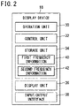
- FIG. 2 is a block diagram showing the display device 18 according to the first embodiment.
- the display device 18, for example, includes a personal computer or a mobile terminal (a tablet type terminal, a smartphone or the like).
- the personal computer or the mobile terminal is capable of communicating with other devices over wires or wirelessly.
- FIG. 1 shows a state in which the display device 18 which includes the personal computer is connected to another device by a fieldbus 20.
- the display device 18 is equipped with an operation unit 30, a control unit 32, a storage unit 34, a display unit 36, and an input/output interface 38.
- the operation unit 30 includes, for example, at least one of a keyboard, a mouse, a touch pad, a touch panel, and a microphone.
- the operation unit 30 is a human-machine interface in order for the user to input data and instructions to the display device 18.
- the data input by the operation unit 30 is stored in the storage unit 34.
- the control unit 32 includes a processor, and more specifically, a processing circuit such as a CPU or the like.
- the control unit 32 administers the control of the display device 18 in its entirety.
- the control unit 32 realizes various functions by executing programs stored in the storage unit 34. For example, the control unit 32, based on information contained in the storage unit 34, determines the occupied frequency bands corresponding to channels or center frequencies input by the operation unit 30. Further, the control unit 32 determines non-recommended frequencies 52 (see FIG. 5 , etc.) and recommended frequencies 54 (see FIG. 5 , etc.), and causes the display unit 36 to display the non-recommended frequencies 52 and the recommended frequencies 54.
- the non-recommended frequencies 52 refer to frequencies that are being used within the 2.4 GHz frequency band.
- the recommended frequencies 54 refer to frequencies that are not being used within the 2.4 GHz frequency band.
- the control unit 32 may be realized by an integrated circuit such as an ASIC, an FPGA, or the like. Further, at least a portion of the control unit 32 may include an electronic circuit containing a discrete device.
- the storage unit 34 includes a volatile memory and a non-volatile memory.
- the volatile memory for example, there may be cited a RAM or the like.
- the non-volatile memory for example, there may be cited a ROM, a flash memory, or the like.
- the volatile memory is used as a working memory for the processor, and temporarily stores data and the like necessary for performing processes or calculations.
- the non-volatile memory there are stored, for example, programs, tables, maps, and the like. At least a portion of the storage unit 34 may be provided in the processor, the integrated circuit, or the like as described above.
- the non-volatile memory of the storage unit 34 stores first frequency information 40 and second frequency information 42.
- the first frequency information 40 is information referred to when the user inputs channels that are already being used. More specifically, the first frequency information 40 is information in which channel numbers and occupied frequency band information are associated with each other. The channel numbers are numbers assigned to the channels assigned to the 2.4 GHz frequency band. The respective channels include occupied frequency bands of 22 MHz.
- the occupied frequency band information is information in relation to each of the occupied frequency bands. For example, the occupied frequency band information includes a center frequency of the occupied frequency band, an upper limit frequency of the occupied frequency band, and a lower limit frequency of the occupied frequency band.
- the first frequency information 40 associates the channel numbers of 1 ch to 14 ch with the occupied frequency bands of the respective channels.
- the non-volatile memory of the first embodiment stores the channels and the occupied frequency bands of the wireless LAN specified by IEEE 802.11b, as the first frequency information 40.
- the first frequency information 40 is set according to the country in which the industrial wireless communication system 10 is provided.
- the second frequency information 42 is information referred to by the control unit 32 when the user inputs center frequencies that are already being used. More specifically, the second frequency information 42 is information indicating a bandwidth (for example, 1 MHz) with the input frequency as the center frequency thereof.
- the display unit 36 includes a monitor such as a liquid crystal display or the like.
- the display unit 36 displays an image 50 (see FIG. 5 , etc.) in response to a display command output from the control unit 32.
- the display unit 36 displays the image 50 in which the non-recommended frequencies 52 and the recommended frequencies 54 are included.
- the input/output interface 38 includes an interface (for example, a connector, a modem, or the like) for the purpose of realizing a fieldbus connection.
- an interface for example, a connector, a modem, or the like
- FIG. 4 is a flowchart showing a display process performed by the display device 18 according to the first embodiment.
- FIGS. 5 and 6 are diagrams showing examples of the image 50 displayed by the display device 18.
- the user Prior to installing a new wireless device in the industrial equipment, the user investigates, with a frequency measuring device or the like, the channels that are already being used in the industrial equipment. The user also investigates, with the frequency measuring device or the like, the frequencies that are already being used in the industrial equipment. Thereafter, the user operates the operation unit 30 and thereby inputs, to the display device 18, at least one of the channel numbers of the channels already being used, or the frequencies already being used. At this time, the user can input a plurality of the channel numbers and a plurality of the frequencies.
- the display device 18 initiates the following display process.
- step S1 the control unit 32 acquires input data from the storage unit 34.
- step S1 the process proceeds to step S2.
- step S2 the control unit 32 determines the occupied frequency bands corresponding to the input data. In the case that the channel numbers are input, the control unit 32 determines the occupied frequency bands corresponding to the channel numbers, with reference to the first frequency information 40. Further, in the case that the frequencies are input, the control unit 32 determines the occupied frequency bands of 1 MHz with the input frequencies as the center frequencies thereof, with reference to the second frequency information 42. When step S2 is completed, the process proceeds to step S3.
- step S3 the control unit 32 determines, as being the non-recommended frequencies 52, the occupied frequency bands determined in step S2.
- the control unit 32 determines, as being the recommended frequencies 54, frequencies other than the non-recommended frequencies 52 included within the 2.4 GHz frequency band. Then, the control unit 32 causes the non-recommended frequencies 52 and the recommended frequencies 54 to be displayed on the display unit 36 so as to be distinguishable from each other.
- the display unit 36 displays the image 50 in response to a display command output from the control unit 32.
- An example of the image 50 is shown in FIG. 5 or FIG. 6 .
- a graph is shown in the image 50. In such a graph, respective frequencies from 2403 MHz to 2481 MHz are arranged in the horizontal direction, and the non-recommended frequencies 52 and the recommended frequencies 54 are shown separately in a vertical direction.
- the display unit 36 displays the image 50 shown in FIG. 5 .
- the display unit 36 displays the 2 ch occupied frequency band as the non-recommended frequencies 52.
- the display unit 36 displays the frequencies other than the non-recommended frequencies 52 as the recommended frequencies 54.
- the non-recommended frequencies 52 are frequencies included within the 2 ch occupied frequency band.
- the minimum frequency of the 2 ch occupied frequency band is 2406 MHz.
- the maximum frequency of the 2 ch occupied frequency band is 2428 MHz.
- the bandwidth of the 2 ch occupied frequency band is 22 MHz.
- the display unit 36 displays the image 50 shown in FIG. 6 .
- the display unit 36 displays the 2403 MHz occupied frequency band as the non-recommended frequencies 52.
- the display unit 36 displays the frequencies other than the non-recommended frequencies 52 as the recommended frequencies 54.
- the non-recommended frequencies 52 are frequencies having 2403 MHz as the center frequency thereof included within a bandwidth of 1 MHz.
- the display unit 36 displays the non-recommended frequencies 52 as a dashed line and the recommended frequencies 54 as a solid line.
- the display unit 36 may display the non-recommended frequencies 52 and the recommended frequencies 54 in different colors.
- the display unit 36 may display each of the non-recommended frequencies 52 and the recommended frequencies 54 by numerical values.
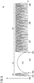
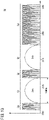
- the display unit 36 may display the non-recommended frequencies 52 and the recommended frequencies 54 in different display forms. For example, as shown in FIG. 7 , the display unit 36 may display the non-recommended frequencies 52 as convex portions 60 that project toward the plus side of the vertical axis. Further, the display unit 36 may display the recommended frequencies 54 as flat portions 62 that overlap with the horizontal axis. Conversely, as shown in FIG. 8 , the display unit 36 may display the recommended frequencies 54 as convex portions 60 that project toward the plus side of the vertical axis. Further, the display unit 36 may display the non-recommended frequencies 52 as flat portions 62 that overlap with the horizontal axis. In this case, the display unit 36 may switch between and display the image 50 shown in FIG. 7 and the image 50 shown in FIG. 8 . Switching between the images 50 may be carried out by an operation performed by the operation unit 30.
- frequencies that are not being used by the industrial equipment are displayed on the display unit 36. Therefore, the user is capable of easily being made aware of the free frequencies existing within a predetermined frequency band, for example, the frequency band of 2.4 GHz.
- Cases may occur in which there are only a few free frequencies available in the 2.4 GHz frequency band, or in which there are no free frequencies available in the 2.4 GHz frequency band.
- not all of the frequencies included within the occupied frequency bands of the channels are in use at all times.
- the respective frequencies included within the occupied frequency band of X ch are not being used in such a time slot.
- interference between the radio waves does not occur.
- a degree of interference between the radio waves which is capable of being tolerated by the user is used as input data for the display device 18.
- FIG. 9 is a block diagram showing the display device 18 according to the second embodiment.
- the same constituent elements as those in the first embodiment are designated by the same reference numerals, and description thereof will be omitted.
- the non-volatile memory of the storage unit 34 stores degree of interference information 44.
- degree of interference information 44 a degree of interference, which will be described below, and an amount of band narrowing, are associated with each other.
- the degree of interference is an allowable amount of the number of times that the radio waves used in a newly provided wireless device and other radio waves interfere with each other within a certain time period.
- the degree of interference also serves as a parameter for specifying an amount of narrowing of the frequency bands displayed as the non-recommended frequencies 52 on the display unit 36.
- the degree of interference is divided into a "small”, a "medium”, and a "large” degree of interference. The larger the degree of interference, the larger the amount of band narrowing that is associated therewith.
- a "small" degree of interference is associated with an amount of band narrowing of "0 MHz”.
- a “medium” degree of interference is associated with an amount of band narrowing of "1 MHz”.
- a "large” degree of interference is associated with an amount of band narrowing of "2 MHz".
- the amount of band narrowing is an amount that acts to shift each of a maximum frequency and a minimum frequency of the occupied frequency bands toward the center frequency side. More specifically, in the case that the degree of interference is "small", each of the channels is displayed on the display unit 36 while the bandwidth of the channel is maintained at 22 MHz. In the case that the degree of interference is "medium”, each of the maximum frequency and the minimum frequency of each of the channels is shifted by 1 MHz toward the center frequency side. Therefore, each of the channels is displayed on the display unit 36 in a state in which the bandwidth of the channel is narrowed from the normal 22 MHz to 20 MHz.
- each of the maximum frequency and the minimum frequency of each of the channels is shifted by 2 MHz toward the center frequency side. Therefore, each of the channels is displayed on the display unit 36 in a state in which the bandwidth of the channel is narrowed from the normal 22 MHz to 18 MHz.
- FIG. 10 is a flowchart showing a display process performed by the display device 18 according to the second embodiment.
- FIGS. 11 to 13 are diagrams showing examples of the image 50 displayed by the display device 18.
- the user operates the operation unit 30 and thereby inputs, to the display device 18, at least one of the channel numbers of the channels already being used in the industrial equipment, or the frequencies already being used in the industrial equipment. Furthermore, the user inputs any one of the degree of interference of "small”, “medium”, and “large”. It should be noted that the default degree of interference is "small”. Therefore, in the case that a "small" degree of interference is desired by the user, the operation of inputting the degree of interference can be omitted.
- the input data is stored in the storage unit 34. When the user performs a predetermined operation on the operation unit 30, the display device 18 initiates the following display process.
- step S11 and the process of step S12 are the same as the process of step S1 and the process of step S2 shown in FIG. 4 .
- step S12 is completed, the process proceeds to step S13.
- step S13 the control unit 32 determines whether or not the channel numbers have been input. In the case that the channel numbers are included in the input data (step S13: YES), the process proceeds to step S14. On the other hand, in the case that the frequencies are input without the channel numbers being input, the channel numbers are not included in the input data. In the case that the channel numbers are not included in the input data (step S13: NO), the process proceeds to step S15.
- step S14 the control unit 32 narrows the occupied frequency bands determined in step S12 by an amount of band narrowing in accordance with the degree of interference input by the user.
- the control unit 32 maintains the occupied frequency bands without change.
- the control unit 32 shifts each of the maximum frequency of the occupied frequency bands and the minimum frequency of the occupied frequency bands by 1 MHz toward the center frequency side.
- the control unit 32 shifts each of the maximum frequency of the occupied frequency bands and the minimum frequency of the occupied frequency bands by 2 MHz toward the center frequency side.
- step S15 is the same as the process of step S3 shown in FIG. 4 .
- the display unit 36 In response to a display command output from the control unit 32, the display unit 36 displays the images 50 shown in FIGS. 11 to 13 , for example.
- the display unit 36 displays the image 50 shown in FIG. 11 .
- the display unit 36 displays each of the 2 ch occupied frequency band and the 7 ch occupied frequency band as the non-recommended frequencies 52.
- the display unit 36 displays the frequencies other than the non-recommended frequencies 52 as the recommended frequencies 54.
- the bandwidth of the frequency bands displayed as the non-recommended frequencies 52 is 22 MHz, which is the bandwidth of a normal occupied frequency band.
- a 2 MHz portion of the recommended frequencies 54 exists between the maximum frequency of the non-recommended frequencies 52 included within the 2 ch occupied frequency band, and the minimum frequency of the non-recommended frequencies 52 included within the 7 ch occupied frequency band.
- the display unit 36 displays the image 50 shown in FIG. 12 .
- the control unit 32 shifts each of the maximum frequency of the 2 ch occupied frequency band and the minimum frequency of the 2 ch occupied frequency band by 1 MHz toward the center frequency side.
- the display unit 36 displays the frequency bands after having been subjected to such a shift correction as the non-recommended frequencies 52.
- the display unit 36 displays the frequencies other than the non-recommended frequencies 52 as the recommended frequencies 54.
- the display unit 36 performs the same process carried out on the 2 ch occupied frequency band, on the 7 ch occupied frequency band.
- the bandwidth of the frequency bands displayed as the non-recommended frequencies 52 is 20 MHz, which is 2 MHz narrower than the bandwidth of the normal occupied frequency band.
- a 4 MHz portion of the recommended frequencies 54 exists between the maximum frequency of the non-recommended frequencies 52 included within the 2 ch occupied frequency band, and the minimum frequency of the non-recommended frequencies 52 included within the 7 ch occupied frequency band.
- the display unit 36 displays the image 50 shown in FIG. 13 .
- the control unit 32 shifts each of the maximum frequency of the 2 ch occupied frequency band and the minimum frequency of the 2 ch occupied frequency band by 2 MHz toward the center frequency side.
- the display unit 36 displays the frequency bands after having been subjected to such a shift correction as the non-recommended frequencies 52.
- the display unit 36 displays the frequencies other than the non-recommended frequencies 52 as the recommended frequencies 54.
- the display unit 36 performs the same process carried out on the 2 ch occupied frequency band, on the 7 ch occupied frequency band.
- the bandwidth of the frequency bands displayed as the non-recommended frequencies 52 is 18 MHz, which is 4 MHz narrower than the bandwidth of the normal occupied frequency band.
- a 6 MHz portion of the recommended frequencies 54 exists between the maximum frequency of the non-recommended frequencies 52 included within the 2 ch occupied frequency band, and the minimum frequency of the non-recommended frequencies 52 included within the 7 ch occupied frequency band.
- the user is capable of being made aware of usable frequencies within a range in which there is an allowable amount of interference.
- the user can specify one of the base wireless devices 14 by operating the operation unit 30.
- the user is capable of setting any arbitrary frequency from among the recommended frequencies 54 displayed on the display unit 36.
- the control unit 32 transmits the frequency selected by the user to the base wireless device 14 that has been selected by the user.
- the base wireless device 14 carries out wireless communication using such a frequency.
- the aspect of the present invention is characterized by the display device 18 which displays, on the display unit 36, the recommended frequencies 54 recommended for use in a wireless device (the base wireless devices 14 and the remote wireless devices 16) that carries out transmission and reception of data by switching between the hopping frequencies in a predetermined frequency band (for example, the frequency band of 2.4 GHz), the display device 18 comprising the storage unit 34 that stores, in association with each other, the plurality of channels or the plurality of center frequencies assigned to the frequency band, and occupied frequency bands that are set to the plurality of channels or the plurality of center frequencies, the operation unit 30 which enables the user to input the channels or the center frequencies, and the control unit 32 that determines, based on the information contained in the storage unit 34, the occupied frequency bands corresponding to the channels or the center frequencies input by the operation unit 30, determines, as the recommended frequencies 54, frequencies included within the frequency band and not included within the determined occupied frequency bands, and causes the display unit 36 to display the recommended frequencies 54.
- a predetermined frequency band for example, the frequency
- frequencies that are not being used are displayed on the display unit 36. Therefore, the user is capable of easily being made aware of the free frequencies existing within a predetermined frequency band, for example, the frequency band of 2.4 GHz.
- the operation unit 30 enables the user to input a degree of interference indicative of an allowable amount of interference between the radio waves used in the wireless device and other radio waves, and the control unit 32 narrows the bandwidth of the occupied frequency bands as the degree of interference increases, and sets, as the recommended frequencies 54, the frequencies included within the frequency band and not included within the narrowed occupied frequency bands.
- the user is capable of being made aware of usable frequencies within a range in which there is an allowable amount of interference.
Landscapes
- Engineering & Computer Science (AREA)
- Signal Processing (AREA)
- Computer Networks & Wireless Communication (AREA)
- Physics & Mathematics (AREA)
- Theoretical Computer Science (AREA)
- Multimedia (AREA)
- General Physics & Mathematics (AREA)
- Computer Hardware Design (AREA)
- Electromagnetism (AREA)
- Human Computer Interaction (AREA)
- General Engineering & Computer Science (AREA)
- Transceivers (AREA)
- Circuits Of Receivers In General (AREA)
- Vehicle Body Suspensions (AREA)
- Diaphragms For Electromechanical Transducers (AREA)
- Measuring Pulse, Heart Rate, Blood Pressure Or Blood Flow (AREA)
- Mobile Radio Communication Systems (AREA)
Abstract
Description
- The present invention relates to a display device that displays frequencies in a predetermined frequency band.
- In
JP H11-261557 A - A 2.4 GHz frequency band (ISM band) is generally open to the public. The number of wireless devices that perform data communication using the 2.4 GHz frequency band is increasing. Therefore, the possibility that interference between radio waves will occur in the 2.4 GHz frequency band is becoming higher.
- In the case that a user who manages industrial equipment newly installs a wireless device in the industrial equipment, it is necessary to set the frequencies used by the wireless device while avoiding frequencies that are already being used. Accordingly, in the case that a plurality of channels are used, it is necessary for the user to investigate which frequencies are not being used. The frequencies that are not being used are also referred to as free frequencies. Such an operation is troublesome for the user to perform.
- The present invention has the object of solving the aforementioned problem.
- One aspect of the present invention is characterized by a display device that displays, on a display unit, recommended frequencies recommended for use in a wireless device configured to carry out transmission and reception of data by switching between hopping frequencies in a predetermined frequency band, the display device comprising a storage unit configured to store, in association with each other, a plurality of channels or a plurality of center frequencies assigned to the frequency band, and occupied frequency bands that are set to the plurality of channels or the plurality of center frequencies, an operation unit configured to enable a user to input the channels or the center frequencies, and a control unit configured to determine, based on information contained in the storage unit, the occupied frequency bands corresponding to the channels or the center frequencies input by the operation unit, to determine, as the recommended frequencies, frequencies included within the frequency band and not included within the determined occupied frequency bands, and to cause the display unit to display the recommended frequencies.
- According to the present invention, the user is capable of easily being made aware of free frequencies existing within a predetermined frequency band.
- The above and other objects, features, and advantages of the present invention will become more apparent from the following description when taken in conjunction with the accompanying drawings, in which preferred embodiments of the present invention are shown by way of illustrative example.
-
-
FIG. 1 is a diagram showing the configuration of an industrial wireless communication system in which a display device is used; -
FIG. 2 is a block diagram showing a display device according to a first embodiment; -
FIG. 3 is a diagram showing an example of first frequency information; -
FIG. 4 is a flowchart showing a display process performed by the display device according to the first embodiment; -
FIG. 5 is a diagram showing an example of an image displayed by the display device; -
FIG. 6 is a diagram showing an example of an image displayed by the display device; -
FIG. 7 is a diagram showing an example of an image displayed by the display device; -
FIG. 8 is a diagram showing an example of an image displayed by the display device; -
FIG. 9 is a block diagram showing a display device according to a second embodiment; -
FIG. 10 is a flowchart showing a display process performed by the display device according to the second embodiment; -
FIG. 11 is a diagram showing an example of an image displayed by the display device; -
FIG. 12 is a diagram showing an example of an image displayed by the display device; and -
FIG. 13 is a diagram showing an example of an image displayed by the display device. -
FIG. 1 is a diagram showing the configuration of an industrialwireless communication system 10 in which adisplay device 18 is used. In the industrialwireless communication system 10, there are provided asingle computer 12, a plurality of basewireless devices 14, a plurality of remotewireless devices 16, and thedisplay device 18. The industrialwireless communication system 10 is equipped with a plurality ofnetworks 22. A single basewireless device 14 and a plurality of remotewireless devices 16 are provided in one of thenetworks 22. Thesingle computer 12, the plurality of basewireless devices 14, and thedisplay device 18 are connected over wires or wirelessly in order to enable communication therebetween. The wired connection may be afieldbus 20. The wireless connection may be by way of short-range wireless communication. The plurality of remotewireless devices 16 are synchronously connected to the single basewireless device 14. - The
computer 12 is capable of monitoring and controlling the industrial equipment. Although not limited to this feature, thecomputer 12 is constituted, for example, by a PLC (programmable logic controller). Thecomputer 12 is capable of carrying out communication with other devices using an input/output interface (not shown). - The base
wireless devices 14 are also referred to as master wireless devices. The basewireless devices 14 are capable of carrying out communication with thecomputer 12 and thedisplay device 18 using an input/output interface (not shown) or a first communication unit (not shown). The basewireless devices 14 are capable of carrying out communication with the remotewireless devices 16 using a second communication unit (not shown) that carries out wireless communication in a frequency band of 2.4 GHz. - The remote
wireless devices 16 are also referred to as slave wireless devices. The remotewireless devices 16 are each provided in each of a plurality of machinery 24 (seeFIG. 1 ) that make up the industrial equipment. Assuch machinery 24, although not limited thereto, there may be cited sensors, valves, and the like. The remotewireless devices 16 are each equipped with a communication unit (not shown) that carries out wireless communication in a frequency band of 2.4 GHz. By using such a communication unit, the remotewireless devices 16 are capable of communicating with the basewireless devices 14. In the example shown inFIG. 1 , one piece of themachinery 24 is provided for each one of the remotewireless devices 16. However, a plurality of themachinery 24 may be provided for each one of the remotewireless devices 16. - The base
wireless devices 14 and the remotewireless devices 16 communicate with each other by way of a frequency hopping method. More specifically, the basewireless devices 14 and the remotewireless devices 16 switch between hopping frequencies at a predetermined hopping cycle to thereby transmit and receive data. -
FIG. 2 is a block diagram showing thedisplay device 18 according to the first embodiment. Thedisplay device 18, for example, includes a personal computer or a mobile terminal (a tablet type terminal, a smartphone or the like). The personal computer or the mobile terminal is capable of communicating with other devices over wires or wirelessly.FIG. 1 shows a state in which thedisplay device 18 which includes the personal computer is connected to another device by afieldbus 20. Thedisplay device 18 is equipped with anoperation unit 30, acontrol unit 32, astorage unit 34, adisplay unit 36, and an input/output interface 38. - The
operation unit 30 includes, for example, at least one of a keyboard, a mouse, a touch pad, a touch panel, and a microphone. Theoperation unit 30 is a human-machine interface in order for the user to input data and instructions to thedisplay device 18. The data input by theoperation unit 30 is stored in thestorage unit 34. - The
control unit 32 includes a processor, and more specifically, a processing circuit such as a CPU or the like. Thecontrol unit 32 administers the control of thedisplay device 18 in its entirety. Thecontrol unit 32 realizes various functions by executing programs stored in thestorage unit 34. For example, thecontrol unit 32, based on information contained in thestorage unit 34, determines the occupied frequency bands corresponding to channels or center frequencies input by theoperation unit 30. Further, thecontrol unit 32 determines non-recommended frequencies 52 (seeFIG. 5 , etc.) and recommended frequencies 54 (seeFIG. 5 , etc.), and causes thedisplay unit 36 to display thenon-recommended frequencies 52 and the recommendedfrequencies 54. Thenon-recommended frequencies 52 refer to frequencies that are being used within the 2.4 GHz frequency band. The recommendedfrequencies 54 refer to frequencies that are not being used within the 2.4 GHz frequency band. Moreover, at least a portion of thecontrol unit 32 may be realized by an integrated circuit such as an ASIC, an FPGA, or the like. Further, at least a portion of thecontrol unit 32 may include an electronic circuit containing a discrete device. - The
storage unit 34 includes a volatile memory and a non-volatile memory. As the volatile memory, for example, there may be cited a RAM or the like. As the non-volatile memory, for example, there may be cited a ROM, a flash memory, or the like. The volatile memory is used as a working memory for the processor, and temporarily stores data and the like necessary for performing processes or calculations. In the non-volatile memory, there are stored, for example, programs, tables, maps, and the like. At least a portion of thestorage unit 34 may be provided in the processor, the integrated circuit, or the like as described above. - The non-volatile memory of the
storage unit 34 storesfirst frequency information 40 andsecond frequency information 42. Thefirst frequency information 40 is information referred to when the user inputs channels that are already being used. More specifically, thefirst frequency information 40 is information in which channel numbers and occupied frequency band information are associated with each other. The channel numbers are numbers assigned to the channels assigned to the 2.4 GHz frequency band. The respective channels include occupied frequency bands of 22 MHz. The occupied frequency band information is information in relation to each of the occupied frequency bands. For example, the occupied frequency band information includes a center frequency of the occupied frequency band, an upper limit frequency of the occupied frequency band, and a lower limit frequency of the occupied frequency band. For example, in the case of a wireless LAN, the communication standard of which is specified by IEEE 802.11b, then as shown inFIG. 3 , thefirst frequency information 40 associates the channel numbers of 1 ch to 14 ch with the occupied frequency bands of the respective channels. The same consideration applies to other wireless communication standards. Moreover, the non-volatile memory of the first embodiment stores the channels and the occupied frequency bands of the wireless LAN specified by IEEE 802.11b, as thefirst frequency information 40. There are cases in which the number of channels used within the 2.4 GHz frequency band are determined independently depending on the country. Thefirst frequency information 40 is set according to the country in which the industrialwireless communication system 10 is provided. On the other hand, thesecond frequency information 42 is information referred to by thecontrol unit 32 when the user inputs center frequencies that are already being used. More specifically, thesecond frequency information 42 is information indicating a bandwidth (for example, 1 MHz) with the input frequency as the center frequency thereof. - The
display unit 36 includes a monitor such as a liquid crystal display or the like. Thedisplay unit 36 displays an image 50 (seeFIG. 5 , etc.) in response to a display command output from thecontrol unit 32. For example, thedisplay unit 36 displays theimage 50 in which thenon-recommended frequencies 52 and the recommendedfrequencies 54 are included. - The input/
output interface 38 includes an interface (for example, a connector, a modem, or the like) for the purpose of realizing a fieldbus connection. -
FIG. 4 is a flowchart showing a display process performed by thedisplay device 18 according to the first embodiment.FIGS. 5 and6 are diagrams showing examples of theimage 50 displayed by thedisplay device 18. Prior to installing a new wireless device in the industrial equipment, the user investigates, with a frequency measuring device or the like, the channels that are already being used in the industrial equipment. The user also investigates, with the frequency measuring device or the like, the frequencies that are already being used in the industrial equipment. Thereafter, the user operates theoperation unit 30 and thereby inputs, to thedisplay device 18, at least one of the channel numbers of the channels already being used, or the frequencies already being used. At this time, the user can input a plurality of the channel numbers and a plurality of the frequencies. When the user performs a predetermined operation on theoperation unit 30, thedisplay device 18 initiates the following display process. - In step S1, the
control unit 32 acquires input data from thestorage unit 34. When step S1 is completed, the process proceeds to step S2. - In step S2, the
control unit 32 determines the occupied frequency bands corresponding to the input data. In the case that the channel numbers are input, thecontrol unit 32 determines the occupied frequency bands corresponding to the channel numbers, with reference to thefirst frequency information 40. Further, in the case that the frequencies are input, thecontrol unit 32 determines the occupied frequency bands of 1 MHz with the input frequencies as the center frequencies thereof, with reference to thesecond frequency information 42. When step S2 is completed, the process proceeds to step S3. - In step S3, the
control unit 32 determines, as being thenon-recommended frequencies 52, the occupied frequency bands determined in step S2. Thecontrol unit 32 determines, as being the recommendedfrequencies 54, frequencies other than thenon-recommended frequencies 52 included within the 2.4 GHz frequency band. Then, thecontrol unit 32 causes thenon-recommended frequencies 52 and the recommendedfrequencies 54 to be displayed on thedisplay unit 36 so as to be distinguishable from each other. Thedisplay unit 36 displays theimage 50 in response to a display command output from thecontrol unit 32. An example of theimage 50 is shown inFIG. 5 orFIG. 6 . A graph is shown in theimage 50. In such a graph, respective frequencies from 2403 MHz to 2481 MHz are arranged in the horizontal direction, and thenon-recommended frequencies 52 and the recommendedfrequencies 54 are shown separately in a vertical direction. - For example, in the case that the user selects 2 ch by operating the
operation unit 30, thedisplay unit 36 displays theimage 50 shown inFIG. 5 . Thedisplay unit 36 displays the 2 ch occupied frequency band as thenon-recommended frequencies 52. Thedisplay unit 36 displays the frequencies other than thenon-recommended frequencies 52 as the recommendedfrequencies 54. Thenon-recommended frequencies 52 are frequencies included within the 2 ch occupied frequency band. The minimum frequency of the 2 ch occupied frequency band is 2406 MHz. The maximum frequency of the 2 ch occupied frequency band is 2428 MHz. The bandwidth of the 2 ch occupied frequency band is 22 MHz. - For example, in the case that the user selects 2403 MHz by operating the
operation unit 30, thedisplay unit 36 displays theimage 50 shown inFIG. 6 . Thedisplay unit 36 displays the 2403 MHz occupied frequency band as thenon-recommended frequencies 52. Thedisplay unit 36 displays the frequencies other than thenon-recommended frequencies 52 as the recommendedfrequencies 54. Thenon-recommended frequencies 52 are frequencies having 2403 MHz as the center frequency thereof included within a bandwidth of 1 MHz. - As shown in
FIGS. 5 and6 , as one example thereof, thedisplay unit 36 displays thenon-recommended frequencies 52 as a dashed line and the recommendedfrequencies 54 as a solid line. However, thedisplay unit 36 may display thenon-recommended frequencies 52 and the recommendedfrequencies 54 in different colors. Alternatively, thedisplay unit 36 may display each of thenon-recommended frequencies 52 and the recommendedfrequencies 54 by numerical values. - The
display unit 36 may display thenon-recommended frequencies 52 and the recommendedfrequencies 54 in different display forms. For example, as shown inFIG. 7 , thedisplay unit 36 may display thenon-recommended frequencies 52 asconvex portions 60 that project toward the plus side of the vertical axis. Further, thedisplay unit 36 may display the recommendedfrequencies 54 asflat portions 62 that overlap with the horizontal axis. Conversely, as shown inFIG. 8 , thedisplay unit 36 may display the recommendedfrequencies 54 asconvex portions 60 that project toward the plus side of the vertical axis. Further, thedisplay unit 36 may display thenon-recommended frequencies 52 asflat portions 62 that overlap with the horizontal axis. In this case, thedisplay unit 36 may switch between and display theimage 50 shown inFIG. 7 and theimage 50 shown inFIG. 8 . Switching between theimages 50 may be carried out by an operation performed by theoperation unit 30. - According to the first embodiment, frequencies that are not being used by the industrial equipment are displayed on the
display unit 36. Therefore, the user is capable of easily being made aware of the free frequencies existing within a predetermined frequency band, for example, the frequency band of 2.4 GHz. - Cases may occur in which there are only a few free frequencies available in the 2.4 GHz frequency band, or in which there are no free frequencies available in the 2.4 GHz frequency band. However, in general, not all of the frequencies included within the occupied frequency bands of the channels are in use at all times. For example, in the case there is no communication data in the X ch (X refers to any one of the
channels 1 to 14) in a certain time slot, the respective frequencies included within the occupied frequency band of X ch are not being used in such a time slot. In this case, even if a newly provided wireless device uses a frequency included within the occupied frequency band of X ch, interference between the radio waves does not occur. In other words, even if a newly provided wireless device uses a frequency included within the occupied frequency band of X ch, there is a possibility that interference between the radio waves may occur from time to time, but not at all times. According to the second embodiment, a degree of interference between the radio waves which is capable of being tolerated by the user is used as input data for thedisplay device 18. -
FIG. 9 is a block diagram showing thedisplay device 18 according to the second embodiment. In the second embodiment, the same constituent elements as those in the first embodiment are designated by the same reference numerals, and description thereof will be omitted. - The non-volatile memory of the
storage unit 34 stores degree ofinterference information 44. In the degree ofinterference information 44, a degree of interference, which will be described below, and an amount of band narrowing, are associated with each other. - The degree of interference is an allowable amount of the number of times that the radio waves used in a newly provided wireless device and other radio waves interfere with each other within a certain time period. The degree of interference also serves as a parameter for specifying an amount of narrowing of the frequency bands displayed as the
non-recommended frequencies 52 on thedisplay unit 36. As one example, the degree of interference is divided into a "small", a "medium", and a "large" degree of interference. The larger the degree of interference, the larger the amount of band narrowing that is associated therewith. According to the second embodiment, a "small" degree of interference is associated with an amount of band narrowing of "0 MHz". A "medium" degree of interference is associated with an amount of band narrowing of "1 MHz". A "large" degree of interference is associated with an amount of band narrowing of "2 MHz". Moreover, the amount of band narrowing is an amount that acts to shift each of a maximum frequency and a minimum frequency of the occupied frequency bands toward the center frequency side. More specifically, in the case that the degree of interference is "small", each of the channels is displayed on thedisplay unit 36 while the bandwidth of the channel is maintained at 22 MHz. In the case that the degree of interference is "medium", each of the maximum frequency and the minimum frequency of each of the channels is shifted by 1 MHz toward the center frequency side. Therefore, each of the channels is displayed on thedisplay unit 36 in a state in which the bandwidth of the channel is narrowed from the normal 22 MHz to 20 MHz. Further, in the case that the degree of interference is "large", each of the maximum frequency and the minimum frequency of each of the channels is shifted by 2 MHz toward the center frequency side. Therefore, each of the channels is displayed on thedisplay unit 36 in a state in which the bandwidth of the channel is narrowed from the normal 22 MHz to 18 MHz. -
FIG. 10 is a flowchart showing a display process performed by thedisplay device 18 according to the second embodiment.FIGS. 11 to 13 are diagrams showing examples of theimage 50 displayed by thedisplay device 18. The user operates theoperation unit 30 and thereby inputs, to thedisplay device 18, at least one of the channel numbers of the channels already being used in the industrial equipment, or the frequencies already being used in the industrial equipment. Furthermore, the user inputs any one of the degree of interference of "small", "medium", and "large". It should be noted that the default degree of interference is "small". Therefore, in the case that a "small" degree of interference is desired by the user, the operation of inputting the degree of interference can be omitted. The input data is stored in thestorage unit 34. When the user performs a predetermined operation on theoperation unit 30, thedisplay device 18 initiates the following display process. - The process of step S11 and the process of step S12 are the same as the process of step S1 and the process of step S2 shown in
FIG. 4 . When step S12 is completed, the process proceeds to step S13. - In step S13, the
control unit 32 determines whether or not the channel numbers have been input. In the case that the channel numbers are included in the input data (step S13: YES), the process proceeds to step S14. On the other hand, in the case that the frequencies are input without the channel numbers being input, the channel numbers are not included in the input data. In the case that the channel numbers are not included in the input data (step S13: NO), the process proceeds to step S15. - In step S14, the
control unit 32 narrows the occupied frequency bands determined in step S12 by an amount of band narrowing in accordance with the degree of interference input by the user. In the case that a "small" degree of interference is input, thecontrol unit 32 maintains the occupied frequency bands without change. In the case that a "medium" degree of interference is input, thecontrol unit 32 shifts each of the maximum frequency of the occupied frequency bands and the minimum frequency of the occupied frequency bands by 1 MHz toward the center frequency side. In the case that a "large" degree of interference is input, thecontrol unit 32 shifts each of the maximum frequency of the occupied frequency bands and the minimum frequency of the occupied frequency bands by 2 MHz toward the center frequency side. When step S14 is completed, the process proceeds to step S15. - The process of step S15 is the same as the process of step S3 shown in
FIG. 4 . In response to a display command output from thecontrol unit 32, thedisplay unit 36 displays theimages 50 shown inFIGS. 11 to 13 , for example. - For example, in the case that the user selects 2 ch and 7 ch and a "small" degree of interference by operating the
operation unit 30, thedisplay unit 36 displays theimage 50 shown inFIG. 11 . Thedisplay unit 36 displays each of the 2 ch occupied frequency band and the 7 ch occupied frequency band as thenon-recommended frequencies 52. Thedisplay unit 36 displays the frequencies other than thenon-recommended frequencies 52 as the recommendedfrequencies 54. In this instance, the bandwidth of the frequency bands displayed as thenon-recommended frequencies 52 is 22 MHz, which is the bandwidth of a normal occupied frequency band. As a result, a 2 MHz portion of the recommendedfrequencies 54 exists between the maximum frequency of thenon-recommended frequencies 52 included within the 2 ch occupied frequency band, and the minimum frequency of thenon-recommended frequencies 52 included within the 7 ch occupied frequency band. - For example, in the case that the user selects 2 ch and 7 ch and a "medium" degree of interference by operating the
operation unit 30, thedisplay unit 36 displays theimage 50 shown inFIG. 12 . Thecontrol unit 32 shifts each of the maximum frequency of the 2 ch occupied frequency band and the minimum frequency of the 2 ch occupied frequency band by 1 MHz toward the center frequency side. Then, thedisplay unit 36 displays the frequency bands after having been subjected to such a shift correction as thenon-recommended frequencies 52. Thedisplay unit 36 displays the frequencies other than thenon-recommended frequencies 52 as the recommendedfrequencies 54. Thedisplay unit 36 performs the same process carried out on the 2 ch occupied frequency band, on the 7 ch occupied frequency band. In this instance, the bandwidth of the frequency bands displayed as thenon-recommended frequencies 52 is 20 MHz, which is 2 MHz narrower than the bandwidth of the normal occupied frequency band. As a result, a 4 MHz portion of the recommendedfrequencies 54 exists between the maximum frequency of thenon-recommended frequencies 52 included within the 2 ch occupied frequency band, and the minimum frequency of thenon-recommended frequencies 52 included within the 7 ch occupied frequency band. - For example, in the case that the user selects 2 ch and 7 ch and a "large" degree of interference by operating the
operation unit 30, thedisplay unit 36 displays theimage 50 shown inFIG. 13 . Thecontrol unit 32 shifts each of the maximum frequency of the 2 ch occupied frequency band and the minimum frequency of the 2 ch occupied frequency band by 2 MHz toward the center frequency side. Then, thedisplay unit 36 displays the frequency bands after having been subjected to such a shift correction as thenon-recommended frequencies 52. Thedisplay unit 36 displays the frequencies other than thenon-recommended frequencies 52 as the recommendedfrequencies 54. Thedisplay unit 36 performs the same process carried out on the 2 ch occupied frequency band, on the 7 ch occupied frequency band. In this instance, the bandwidth of the frequency bands displayed as thenon-recommended frequencies 52 is 18 MHz, which is 4 MHz narrower than the bandwidth of the normal occupied frequency band. As a result, a 6 MHz portion of the recommendedfrequencies 54 exists between the maximum frequency of thenon-recommended frequencies 52 included within the 2 ch occupied frequency band, and the minimum frequency of thenon-recommended frequencies 52 included within the 7 ch occupied frequency band. - According to the second embodiment, even in the case that there are no free frequencies, the user is capable of being made aware of usable frequencies within a range in which there is an allowable amount of interference.
- The user can specify one of the
base wireless devices 14 by operating theoperation unit 30. The user is capable of setting any arbitrary frequency from among the recommendedfrequencies 54 displayed on thedisplay unit 36. Thecontrol unit 32 transmits the frequency selected by the user to thebase wireless device 14 that has been selected by the user. Thebase wireless device 14 carries out wireless communication using such a frequency. - Hereinafter, technical concepts which are capable of being grasped from the above-described embodiments will be described.
- The aspect of the present invention is characterized by the
display device 18 which displays, on thedisplay unit 36, the recommendedfrequencies 54 recommended for use in a wireless device (thebase wireless devices 14 and the remote wireless devices 16) that carries out transmission and reception of data by switching between the hopping frequencies in a predetermined frequency band (for example, the frequency band of 2.4 GHz), thedisplay device 18 comprising thestorage unit 34 that stores, in association with each other, the plurality of channels or the plurality of center frequencies assigned to the frequency band, and occupied frequency bands that are set to the plurality of channels or the plurality of center frequencies, theoperation unit 30 which enables the user to input the channels or the center frequencies, and thecontrol unit 32 that determines, based on the information contained in thestorage unit 34, the occupied frequency bands corresponding to the channels or the center frequencies input by theoperation unit 30, determines, as the recommendedfrequencies 54, frequencies included within the frequency band and not included within the determined occupied frequency bands, and causes thedisplay unit 36 to display the recommendedfrequencies 54. - According to the above-described configuration, frequencies that are not being used are displayed on the
display unit 36. Therefore, the user is capable of easily being made aware of the free frequencies existing within a predetermined frequency band, for example, the frequency band of 2.4 GHz. - In the aspect of the present invention, the
operation unit 30 enables the user to input a degree of interference indicative of an allowable amount of interference between the radio waves used in the wireless device and other radio waves, and thecontrol unit 32 narrows the bandwidth of the occupied frequency bands as the degree of interference increases, and sets, as the recommendedfrequencies 54, the frequencies included within the frequency band and not included within the narrowed occupied frequency bands. - According to the above-described configuration, even in the case that there are no free frequencies, the user is capable of being made aware of usable frequencies within a range in which there is an allowable amount of interference.
Claims (2)
- A display device (18) that displays, on a display unit (36), recommended frequencies (54) recommended for use in a wireless device (14, 16) configured to carry out transmission and reception of data by switching between hopping frequencies in a predetermined frequency band, the display device comprising:a storage unit (34) configured to store, in association with each other, a plurality of channels or a plurality of center frequencies assigned to the frequency band, and occupied frequency bands that are set to the plurality of channels or the plurality of center frequencies;an operation unit (30) configured to enable a user to input the channels or the center frequencies; anda control unit (32) configured to determine, based on information contained in the storage unit, the occupied frequency bands corresponding to the channels or the center frequencies input by the operation unit, to determine, as the recommended frequencies, frequencies included within the frequency band and not included within the determined occupied frequency bands, and to cause the display unit to display the recommended frequencies.
- The display device according to claim 1, wherein:the operation unit enables the user to input a degree of interference indicative of an allowable amount of interference between radio waves used in the wireless device and other radio waves; andthe control unit narrows a bandwidth of the occupied frequency bands as the degree of interference increases, and sets, as the recommended frequencies, frequencies included within the frequency band and not included within the narrowed occupied frequency bands.
Applications Claiming Priority (1)
| Application Number | Priority Date | Filing Date | Title |
|---|---|---|---|
| JP2021039037A JP7376014B2 (en) | 2021-03-11 | 2021-03-11 | display device |
Publications (1)
| Publication Number | Publication Date |
|---|---|
| EP4057748A1 true EP4057748A1 (en) | 2022-09-14 |
Family
ID=80683711
Family Applications (1)
| Application Number | Title | Priority Date | Filing Date |
|---|---|---|---|
| EP22160694.0A Pending EP4057748A1 (en) | 2021-03-11 | 2022-03-08 | Display device |
Country Status (6)
| Country | Link |
|---|---|
| US (1) | US12021573B2 (en) |
| EP (1) | EP4057748A1 (en) |
| JP (1) | JP7376014B2 (en) |
| KR (1) | KR102901276B1 (en) |
| CN (1) | CN115085762A (en) |
| IL (1) | IL291227B2 (en) |
Citations (2)
| Publication number | Priority date | Publication date | Assignee | Title |
|---|---|---|---|---|
| US20040239591A1 (en) * | 2003-05-07 | 2004-12-02 | Nec Corporation | Plasma display device and method of reducing interference to radio-broadcasting waves, caused by electromagnetic waves derived from plasma display device |
| US20100194985A1 (en) * | 2009-01-30 | 2010-08-05 | Sony Corporation | Method and system for displaying a wireless channel space on a display device |
Family Cites Families (8)
| Publication number | Priority date | Publication date | Assignee | Title |
|---|---|---|---|---|
| JPH11261557A (en) | 1998-03-10 | 1999-09-24 | Omron Corp | Wireless communication device |
| JP2004159018A (en) | 2002-11-05 | 2004-06-03 | Ricoh Co Ltd | Signal strength measurement device |
| JP3742057B2 (en) | 2002-12-25 | 2006-02-01 | 株式会社バッファロー | Analysis technology of radio wave condition in wireless information communication |
| JP4073322B2 (en) * | 2003-01-23 | 2008-04-09 | 株式会社日立製作所 | Spread spectrum wireless communication system and control program |
| JP4544119B2 (en) | 2005-09-27 | 2010-09-15 | サクサ株式会社 | Wireless communication apparatus and program |
| US8340157B2 (en) | 2009-07-28 | 2012-12-25 | Interlite Aktiebolag | Methods and devices for wireless communication in wireless communication systems |
| KR20170101077A (en) * | 2016-02-26 | 2017-09-05 | 삼성전자주식회사 | Server, Electronic device and operating method for the same |
| JP6455502B2 (en) | 2016-12-13 | 2019-01-23 | カシオ計算機株式会社 | Communication terminal device and program |
-
2021
- 2021-03-11 JP JP2021039037A patent/JP7376014B2/en active Active
-
2022
- 2022-03-08 EP EP22160694.0A patent/EP4057748A1/en active Pending
- 2022-03-09 US US17/654,155 patent/US12021573B2/en active Active
- 2022-03-09 IL IL291227A patent/IL291227B2/en unknown
- 2022-03-10 CN CN202210230983.2A patent/CN115085762A/en active Pending
- 2022-03-11 KR KR1020220030725A patent/KR102901276B1/en active Active
Patent Citations (2)
| Publication number | Priority date | Publication date | Assignee | Title |
|---|---|---|---|---|
| US20040239591A1 (en) * | 2003-05-07 | 2004-12-02 | Nec Corporation | Plasma display device and method of reducing interference to radio-broadcasting waves, caused by electromagnetic waves derived from plasma display device |
| US20100194985A1 (en) * | 2009-01-30 | 2010-08-05 | Sony Corporation | Method and system for displaying a wireless channel space on a display device |
Also Published As
| Publication number | Publication date |
|---|---|
| IL291227B2 (en) | 2025-12-01 |
| CN115085762A (en) | 2022-09-20 |
| US12021573B2 (en) | 2024-06-25 |
| US20220294544A1 (en) | 2022-09-15 |
| IL291227A (en) | 2022-10-01 |
| IL291227B1 (en) | 2025-08-01 |
| JP2022138898A (en) | 2022-09-26 |
| JP7376014B2 (en) | 2023-11-08 |
| KR20220127768A (en) | 2022-09-20 |
| KR102901276B1 (en) | 2025-12-17 |
Similar Documents
| Publication | Publication Date | Title |
|---|---|---|
| JP2004531172A (en) | Integrated remote controller device and control method therefor | |
| JP2020088558A (en) | Mobile terminal test device, mobile terminal test system, and nsa test method | |
| EP4057677B1 (en) | Display system | |
| US12021573B2 (en) | Display device | |
| JP7461398B2 (en) | Mobile terminal testing system and mobile terminal testing method | |
| US11206186B2 (en) | Measurement apparatus and measurement method | |
| JP2011114416A (en) | Radio wave state display device | |
| JP7472186B2 (en) | Mobile terminal test system and mobile terminal test method | |
| JP7399199B2 (en) | Radio interference monitoring device and radio interference monitoring method | |
| JP7421537B2 (en) | Mobile terminal test equipment and its parameter setting method | |
| JP2009171257A (en) | Wireless communication system | |
| CN115133944B (en) | Display system | |
| JP4544119B2 (en) | Wireless communication apparatus and program | |
| US9984483B2 (en) | Mobile terminal testing device and mobile terminal testing method | |
| JP7480106B2 (en) | Mobile terminal test device and band filter setting method thereof | |
| US12431987B2 (en) | Mobile terminal testing device and method for displaying EVM measurement result of SRS using same | |
| US20230156495A1 (en) | Mobile terminal testing system and parameter setting method thereof | |
| JP4604941B2 (en) | Wireless communication apparatus and program | |
| JP2019032702A (en) | Test support system for monitoring control system, test support method for monitoring control system, and terminal device | |
| JP5070238B2 (en) | Mobile communication device test system and test method | |
| JP2022065779A (en) | Mobile terminal test device and abnormal-time-processing selection method thereof | |
| JP2006333308A (en) | Bluetooth(r) communication apparatus and program | |
| JP2011055097A (en) | Wireless communication device | |
| JP2010178108A (en) | Radio communication apparatus and radio communication control method |
Legal Events
| Date | Code | Title | Description |
|---|---|---|---|
| PUAI | Public reference made under article 153(3) epc to a published international application that has entered the european phase |
Free format text: ORIGINAL CODE: 0009012 |
|
| STAA | Information on the status of an ep patent application or granted ep patent |
Free format text: STATUS: THE APPLICATION HAS BEEN PUBLISHED |
|
| AK | Designated contracting states |
Kind code of ref document: A1 Designated state(s): AL AT BE BG CH CY CZ DE DK EE ES FI FR GB GR HR HU IE IS IT LI LT LU LV MC MK MT NL NO PL PT RO RS SE SI SK SM TR |
|
| STAA | Information on the status of an ep patent application or granted ep patent |
Free format text: STATUS: REQUEST FOR EXAMINATION WAS MADE |
|
| 17P | Request for examination filed |
Effective date: 20230222 |
|
| RBV | Designated contracting states (corrected) |
Designated state(s): AL AT BE BG CH CY CZ DE DK EE ES FI FR GB GR HR HU IE IS IT LI LT LU LV MC MK MT NL NO PL PT RO RS SE SI SK SM TR |
|
| STAA | Information on the status of an ep patent application or granted ep patent |
Free format text: STATUS: EXAMINATION IS IN PROGRESS |
|
| 17Q | First examination report despatched |
Effective date: 20240912 |
|
| RAP3 | Party data changed (applicant data changed or rights of an application transferred) |
Owner name: SMC CORPORATION |