EP4057727A1 - Method and device for information processing, storage medium, and chip - Google Patents
Method and device for information processing, storage medium, and chip Download PDFInfo
- Publication number
- EP4057727A1 EP4057727A1 EP19951411.8A EP19951411A EP4057727A1 EP 4057727 A1 EP4057727 A1 EP 4057727A1 EP 19951411 A EP19951411 A EP 19951411A EP 4057727 A1 EP4057727 A1 EP 4057727A1
- Authority
- EP
- European Patent Office
- Prior art keywords
- uplink duty
- duty cycle
- network device
- terminal
- maximum
- Prior art date
- Legal status (The legal status is an assumption and is not a legal conclusion. Google has not performed a legal analysis and makes no representation as to the accuracy of the status listed.)
- Granted
Links
Images


Classifications
-
- H—ELECTRICITY
- H04—ELECTRIC COMMUNICATION TECHNIQUE
- H04W—WIRELESS COMMUNICATION NETWORKS
- H04W52/00—Power management, e.g. Transmission Power Control [TPC] or power classes
- H04W52/04—Transmission power control [TPC]
- H04W52/30—Transmission power control [TPC] using constraints in the total amount of available transmission power
- H04W52/36—Transmission power control [TPC] using constraints in the total amount of available transmission power with a discrete range or set of values, e.g. step size, ramping or offsets
- H04W52/367—Power values between minimum and maximum limits, e.g. dynamic range
-
- H—ELECTRICITY
- H04—ELECTRIC COMMUNICATION TECHNIQUE
- H04B—TRANSMISSION
- H04B1/00—Details of transmission systems, not covered by a single one of groups H04B3/00 - H04B13/00; Details of transmission systems not characterised by the medium used for transmission
- H04B1/38—Transceivers, i.e. devices in which transmitter and receiver form a structural unit and in which at least one part is used for functions of transmitting and receiving
- H04B1/3827—Portable transceivers
-
- H—ELECTRICITY
- H04—ELECTRIC COMMUNICATION TECHNIQUE
- H04B—TRANSMISSION
- H04B1/00—Details of transmission systems, not covered by a single one of groups H04B3/00 - H04B13/00; Details of transmission systems not characterised by the medium used for transmission
- H04B1/38—Transceivers, i.e. devices in which transmitter and receiver form a structural unit and in which at least one part is used for functions of transmitting and receiving
- H04B1/3827—Portable transceivers
- H04B1/3833—Hand-held transceivers
- H04B1/3838—Arrangements for reducing RF exposure to the user, e.g. by changing the shape of the transceiver while in use
-
- H—ELECTRICITY
- H04—ELECTRIC COMMUNICATION TECHNIQUE
- H04W—WIRELESS COMMUNICATION NETWORKS
- H04W52/00—Power management, e.g. Transmission Power Control [TPC] or power classes
- H04W52/04—Transmission power control [TPC]
- H04W52/06—TPC algorithms
- H04W52/14—Separate analysis of uplink or downlink
- H04W52/146—Uplink power control
-
- H—ELECTRICITY
- H04—ELECTRIC COMMUNICATION TECHNIQUE
- H04W—WIRELESS COMMUNICATION NETWORKS
- H04W72/00—Local resource management
- H04W72/04—Wireless resource allocation
- H04W72/044—Wireless resource allocation based on the type of the allocated resource
- H04W72/0446—Resources in time domain, e.g. slots or frames
-
- H—ELECTRICITY
- H04—ELECTRIC COMMUNICATION TECHNIQUE
- H04W—WIRELESS COMMUNICATION NETWORKS
- H04W72/00—Local resource management
- H04W72/12—Wireless traffic scheduling
- H04W72/1263—Mapping of traffic onto schedule, e.g. scheduled allocation or multiplexing of flows
-
- H—ELECTRICITY
- H04—ELECTRIC COMMUNICATION TECHNIQUE
- H04W—WIRELESS COMMUNICATION NETWORKS
- H04W52/00—Power management, e.g. Transmission Power Control [TPC] or power classes
- H04W52/04—Transmission power control [TPC]
- H04W52/06—TPC algorithms
- H04W52/16—Deriving transmission power values from another channel
-
- H—ELECTRICITY
- H04—ELECTRIC COMMUNICATION TECHNIQUE
- H04W—WIRELESS COMMUNICATION NETWORKS
- H04W52/00—Power management, e.g. Transmission Power Control [TPC] or power classes
- H04W52/04—Transmission power control [TPC]
- H04W52/38—TPC being performed in particular situations
- H04W52/44—TPC being performed in particular situations in connection with interruption of transmission
-
- H—ELECTRICITY
- H04—ELECTRIC COMMUNICATION TECHNIQUE
- H04W—WIRELESS COMMUNICATION NETWORKS
- H04W72/00—Local resource management
- H04W72/12—Wireless traffic scheduling
- H04W72/1263—Mapping of traffic onto schedule, e.g. scheduled allocation or multiplexing of flows
- H04W72/1268—Mapping of traffic onto schedule, e.g. scheduled allocation or multiplexing of flows of uplink data flows
Definitions
- Embodiments of the present application relate to electronic technology, and relate to but are not limited to a method and device for information processing, a storage medium, and a chip.
- SAR Specific Absorption Rate
- the SAR index is the average measured value of the terminal in a certain period of time. The higher the terminal transmission power, the higher the SAR value; or, the longer the uplink transmission time, the higher the SAR value.
- the Maximum Permissible Emission is an index parameter for measuring the electromagnetic radiation intensity of the terminal to human body.
- MPE index is the average measured value of the power density of the terminal in a certain area within a certain period of time. The higher the terminal transmission power, the higher the MPE value.
- a terminal In order to meet SAR and MPE target indexes, a terminal often uses, for example, a range sensor to detect a distance between the terminal and a human body and performs power back-off to reduce the transmission power when the terminal gets close to the human body, so as to avoid the problem of SAR and MPE limit-exceeding.
- a range sensor to detect a distance between the terminal and a human body and performs power back-off to reduce the transmission power when the terminal gets close to the human body, so as to avoid the problem of SAR and MPE limit-exceeding.
- embodiments of the present application provide a method and device for information processing, a storage medium, and a chip.
- an embodiment of the present application provides a method for information processing, applied to a terminal, the method includes: determining multiple predefined uplink duty cycles corresponding to a first network device; determining multiple maximum uplink duty cycles that can be scheduled by a second network device, wherein there is a correspondence relation between the multiple maximum uplink duty cycles and the multiple predefined uplink duty cycles; and reporting the multiple maximum uplink duty cycles, wherein the multiple maximum uplink duty cycles are used for the second network device to select, according to a specific strategy, a referenced maximum uplink duty cycle from the multiple maximum uplink duty cycles when scheduling a transmission time of the terminal.
- an embodiment of the present application further provides a method for information processing, applied to a network device, the method includes: acquiring multiple maximum uplink duty cycles reported by a terminal; selecting a referenced maximum uplink duty cycle from the multiple maximum uplink duty cycles according to a specific strategy; and scheduling a transmission time of the terminal according to the referenced maximum uplink duty cycle.
- an embodiment of the present application provides a terminal device, including: a determining module, configured to determine multiple predefined uplink duty cycles corresponding to a first network device; and determine multiple maximum uplink duty cycles that can be scheduled by a second network device, wherein there is a correspondence relation between the multiple maximum uplink duty cycles and the multiple predefined uplink duty cycles; and a reporting module, configured to report the multiple maximum uplink duty cycles, wherein the multiple maximum uplink duty cycles are used for the second network device to select, according to a specific strategy, a referenced maximum uplink duty cycle from the multiple maximum uplink duty cycles when scheduling a transmission time of the terminal.
- an embodiment of the present application further provides a network device, including: an acquiring module, configured to acquire multiple maximum uplink duty cycles reported by a terminal; a selecting module, configured to select a referenced maximum uplink duty cycle from the multiple maximum uplink duty cycles according to a specific strategy; and a scheduling module, configured to schedule a transmission time of the terminal according to the referenced maximum uplink duty cycle.
- an embodiment of the present application provides a terminal device, including a first memory and a first processor, wherein the first memory stores a computer program which is runnable on the first processor, and the acts of the method for information processing of the embodiments of the present application are implemented when the first processor executes the computer program.
- an embodiment of the present application provides a network device, including a second memory and a second processor, wherein the second memory stores a computer program which is runnable on the second processor, and the acts of the method for information processing of the embodiments of the present application are implemented when the second processor executes the computer program.
- an embodiment of the present application provides a computer readable storage medium, on which a computer program is stored, wherein when the computer program is executed by a processor, acts in the methods for information processing of the embodiments of the present application are implemented.
- an embodiment of the present application provides a chip, including a processor configured for calling and running a computer program from a memory, to cause a device installed with the chip to perform the method for information processing of the terminal side in the embodiments of the present application; or, to cause a device installed with the chip to perform the method for information processing of the network device side in the embodiments of the present application.
- a terminal reports multiple maximum uplink duty cycles that can be scheduled by a second network device, so that the second network device can adaptively select a referenced maximum uplink duty cycle from the multiple maximum uplink duty cycles according to uplink duty cycles actually scheduled by a first network device. Therefore, under different uplink duty cycle configurations of a first network device, a second network device can correspondingly adjust a referenced maximum uplink duty cycle capability, thus maximally ensuring that the terminal can meet SAR requirements while maintaining maximum power transmission.
- first/second/third in the embodiments of the present application are only for distinguishing similar objects, but do not represent a specific order for objects. Understandably, the "first/second/third” can be interchanged in a specific order or a sequence if allowed, so that the embodiments of the present application described here can be implemented in an order other than that illustrated or described here.
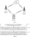
- FIG. 1 is a schematic diagram of a structure of communication architecture according to an embodiment of the present application.
- the communication architecture at least includes a terminal 10, a first network device 11, a second network device 12, and a core network 13; wherein, the terminal 10 achieves communication under multiple connections by accessing the first network device 11 and the second network device 12; both the first network device 11 and the second network device 12 are connected to the core network 13.
- terminals may also access three or more network devices simultaneously to achieve communication under multiple connections.
- terminals can be various types of devices with communication capabilities, such as cell phones, tablet computers, digital phones, video phones, smart watches, etc.
- An embodiment of the present application provides a method for information processing, wherein the method is applied to a terminal, and a function realized by the method may be achieved by a processor in the terminal for calling program codes.
- the program codes may be stored in a computer storage medium, it shows that the terminal at least includes a processor and a storage medium.
- FIG. 2 is a schematic flowchart of an implementation of a method for information processing according to an embodiment of the present application. As shown in FIG. 2 , the method at least includes the following acts 201 to 203.
- the uplink duty cycle refers to the percentage of uplink slots in the sum of uplink slots and downlink slots (i.e., the length of a time window) in the time window. For example, when a transmission time for transmitting signals by a terminal to a first network device within a time window is t1, and when a transmission time for transmitting signals by the first network device to the terminal within the time window is t2, then the uplink duty cycle within the time window is t1/(t1+t2).
- a first network device is usually a device which is first accessed and regarded as a primary cell by the terminal.
- a first network device is a base station adopting Long Term Evolution (LTE) (hereinafter referred to as LTE base station), or is a base station adopting the 5th-Generation New radio (NR base station).
- LTE base station Long Term Evolution
- NR base station 5th-Generation New radio
- the terminal acquires multiple predefined uplink duty cycles corresponding to the LTE base station from pre-stored predefined uplink duty cycle information, or requests the LTE base station for the corresponding predefined uplink duty cycles.
- the first network device is an NR base station
- the way in which the terminal acquires multiple predefined duty cycles corresponding to the NR base station is similar to that in the above-mentioned approach, and will not be repeated here.
- a predefined uplink duty cycle corresponds to a maximum uplink duty cycle. Multiple predefined uplink duty cycles are different, and a size relationship among multiple maximum uplink duty cycles is not limited.
- a mode of a second network device may be identical or different from that of a first network device.
- the modes may be different, for example, the first network device is an LTE base station and the second network device is an NR base station, for another example, the first network device is an NR base station and the second network device is an LTE base station.
- a terminal For a terminal under multiple connections, in order to prevent the SAR value from exceeding the limit, the terminal needs to limit transmission powers and transmission times of the antennas corresponding to the first network device and the second network device respectively.
- a terminal can determine each maximum uplink duty cycle according to the attribute parameter information of its own antenna (such as antenna position and antenna efficiency, etc.).
- uplink duty cycles corresponding to an LTE base station are predefined multiple values (i.e. LTE predefined uplink duty cycle in Table 1), and maximum uplink duty cycles that can be scheduled by an NR base station are reported to the network as terminal capability.
- the maximum uplink duty cycle that can be scheduled by an NR base station corresponding to LTE predefined uplink duty cycle DutyLTE1 is maxULdutycycle-EN-DC1.
- the maximum uplink duty cycle that can be scheduled by an NR base station corresponding to LTE predefined uplink duty cycle DutyLTEn is maxULdutycycle-EN-DCn.
- uplink duty cycles corresponding to an NR base station are predefined multiple values (i.e. NR predefined uplink duty cycle in Table 2), and maximum uplink duty cycles that can be scheduled by an LTE base station are reported to the network as terminal capability.
- NR predefined uplink duty cycle in Table 2 there is a correspondence relation between the parameters in the same row.
- Table 2 NR predefined uplink duty cycle LTE base station schedulable Maximum uplink duty cycle DutyNR1 maxULdutycycle-NE-DC 1 DutyNR2 maxULdutycycle-NE-DC2 ... ... DutyNRm maxULdutycycle-NE-DCm DutyNRn maxULdutycycle-NE-DCn
- the multiple maximum uplink duty cycles are reported, the multiple maximum uplink duty cycles are used for the second network device to select, according to a specific strategy, a reference maximum uplink duty cycle from the multiple maximum uplink duty cycles when scheduling a transmission time of the terminal.
- both sides need to make clear which maximum uplink duty cycle is referenced when scheduling uplink duty cycles in the same arbitrary time window.
- the second network device needs to determine which one of the reported multiple maximum uplink duty cycles should be the upper limit for scheduling the uplink duty cycle of the terminal.
- a second network device can schedule the transmission time of the terminal, so that the uplink duty cycle of the terminal within a time window is less than or equal to the referenced maximum uplink duty cycle.
- the terminal reports multiple maximum uplink duty cycles that can be scheduled by the second network device, the multiple maximum uplink duty cycles are used for the second network device to, according to an uplink duty cycle actually scheduled by a first network device, adaptively select a referenced maximum uplink duty cycle from the multiple maximum uplink duty cycles reported by the terminal. Therefore, when a first network device uses different uplink duty cycle configurations, a second network device can correspondingly adjust the referenced maximum uplink duty cycle capability, thus maximally ensuring that the terminal can meet SAR requirements while maintaining maximum power transmission.
- FIG. 3 is a schematic flowchart of another implementation of a method for information processing according to an embodiment of the present application. As shown in FIG. 3 , the method at least includes the following acts 301 to 308.
- a terminal determines multiple predefined uplink duty cycles corresponding to a first network device.
- the terminal device determines multiple maximum uplink duty cycles that can be scheduled by a second network device, there is a correspondence relation between the multiple maximum uplink duty cycles and the multiple predefined uplink duty cycles.
- the terminal reports the multiple maximum uplink duty cycles.
- a terminal reports multiple maximum uplink duty cycles to a first network device in the process of accessing the first network device with the first network device being a primary cell, wherein the first network device is used for informing a second network device of the multiple maximum uplink duty cycles. In this way, the terminal does not need to separately report this information to the second network device in the subsequent interaction, thus saving network resources and reducing the complexity of information interaction.
- a first network device after acquiring information of the multiple maximum uplink duty cycles reported by a terminal, can directly forward the information to a second network device, or forward the information to a core network and the core network can send the information to the second network device.
- a second network device acquires multiple maximum uplink duty cycles reported by the terminal.
- the second network device selects a referenced maximum uplink duty cycle from the multiple maximum uplink duty cycles according to a specific strategy in any time window.
- the second network device can dynamically monitor the uplink duty cycle actually scheduled by the first network device, so as to adaptively adjust the current referenced maximum uplink duty cycle, and further ensure that the terminal can maintain the maximum transmission power capability to the maximum extent while meeting the SAR index. For example, the second network device periodically performs monitoring, and the length of each period is the length of a time window.
- the second network device can implement Act 305 by performing acts 405 to 409 in the following embodiment, so as to select the referenced maximum uplink duty cycle from the multiple maximum uplink duty cycles when scheduling the uplink duty cycles for the terminal in any time window.
- a second network device schedules the transmission time of the terminal according to the referenced maximum uplink duty cycle.
- the terminal acquires a first uplink duty cycle actually scheduled by the first network device for the terminal in the time window.
- the terminal acquires the first uplink duty cycle
- the terminal itself can count the first uplink duty cycle actually scheduled by the first network device for the terminal in each time window.
- the terminal may also receive the first uplink duty cycle information sent by the first network device.
- the terminal can dynamically monitor the first uplink duty cycle actually scheduled by the first network device for the terminal. For example, the terminal performs monitoring periodically, and the length of each period is the length of the time window.
- the first network device may transmit the first uplink duty cycle information to the terminal.
- the first network device can transmit actively or passively based on the request message sent by the terminal. For actively transmitting, the first network device can periodically transmit, or can inform the terminal when the first uplink duty cycle changes.
- a first uplink duty cycle and a second uplink duty cycle described below do not specifically refer to a specific uplink duty cycle, but a description in a general sense, where "first" and “second” are only used to distinguish that uplink duty cycles are scheduled by different network devices.
- the first uplink duty cycle is an uplink duty cycle actually scheduled by a first network device for the terminal.
- the second uplink duty cycle is an uplink duty cycle actually scheduled by a second network device for the terminal.
- the following first sum does not specifically refer to a specific value.
- a terminal determines a first sum of uplink slots actually scheduled by the first network device for the terminal within any aforementioned time window; the terminal determines a ratio of the first sum to a length of the time window as the first uplink duty cycle.
- the terminal controls a transmission power according to a relationship between the first uplink duty cycle and the multiple predefined uplink duty cycles.
- a terminal can report information of multiple maximum uplink duty cycles, so that a second network device can schedule the transmission time of the terminal by using other uplink duty cycle capabilities when the uplink duty cycle actually scheduled by the first network device exceeds a certain value. In this way, the terminal does not have to carry out power back-off, and the power capability of the terminal can be effectively utilized.
- FIG. 4 is a schematic flowchart of yet another implementation of a method for information processing according to an embodiment of the present application. As shown in FIG. 4 , the method at least includes the following acts 401 to 417.
- a terminal determines multiple predefined uplink duty cycles corresponding to a first network device.
- the terminal device determines multiple maximum uplink duty cycles that can be scheduled by a second network device, there is a correspondence relation between the multiple maximum uplink duty cycles and the multiple predefined uplink duty cycles.
- the terminal reports the multiple maximum uplink duty cycles.
- the second network device acquires information of multiple maximum uplink duty cycles reported by the terminal.
- the second network device acquires a first uplink duty cycle actually scheduled by the first network device for the terminal in any time window.
- a first network device can dynamically monitor an uplink duty cycle actually scheduled by the first network device itself for a terminal, and then send the monitoring result to a second network device.
- the first network device periodically monitors an uplink duty cycle actually scheduled by the first network device itself for the terminal, and then sends the monitoring result obtained every time to the second network device, or sends the monitoring result to the second network device when the monitoring result changes.
- a length of the monitoring period can be the length of a time window.
- a second network device acquires multiple predefined uplink duty cycles of a first network device.
- the second network device can acquire information of multiple predefined uplink duty cycles of the first network device from the core network or the first network device.
- the second network device may also acquire the information of the multiple predefined uplink duty cycles from data pre-stored in the second network device itself.
- a second network device determines a relationship between the first uplink duty cycle and the maximum value of the predefined uplink duty cycles; when the first uplink duty cycle is less than or equal to the maximum value, Act 408 is executed; otherwise, Act 411 is executed.
- the second network device selects a target predefined uplink duty cycle from the multiple predefined uplink duty cycles.
- a second network device can determine a difference value between the first uplink duty cycle and each predefined uplink duty cycle; the second network device determines a larger one of the predefined uplink duty cycles corresponding to two minimum difference values as a target predefined uplink duty cycle when each difference value is not zero; and when one of the determined difference values is zero, the second network device determines a predefined uplink duty cycle corresponding to the determined difference value of zero as the target predefined uplink duty cycle.
- the target predefined uplink duty cycle is 20%; when the first uplink duty cycle is 25%, which is between 20% and 30%, the larger value, 30%, is taken as the target predefined uplink duty cycle.
- the second network device determines the maximum uplink duty cycle corresponding to the target predefined uplink duty cycle as the referenced maximum uplink duty cycle.
- DutyLTE1 DutyLTE2
- DutyLTE2 the uplink duty cycle actually scheduled by the LTE base station
- DutyLTE2 the uplink duty cycle actually scheduled by the LTE base station
- the referenced maximum uplink duty cycle is DutyLTEnmaxULdutycycle-EN-DC2 en-dc2.
- the second network device monitors that the uplink duty cycle actually scheduled by the LTE base station is between DutyLTEm and DutyLTEn, it selects a larger one, i.e. DutyLTEn, as the target predefined uplink duty cycle; accordingly, the referenced maximum uplink duty cycle is DutyLTEnmaxULdutycycle-EN-DCn.
- the second network device schedules the transmission time of the terminal according to the referenced maximum uplink duty cycle.
- the second network device performs one of the following acts when the first uplink duty cycle is greater than the maximum value of the multiple predefined uplink duty cycles: removing limitation on the maximum uplink duty cycle, keeping the current referenced maximum uplink duty cycle, or reducing the current referenced maximum uplink duty cycle.
- Act 405 to Act 409 are implementation acts for the second network device to determine the referenced maximum uplink duty cycle in any time window. In fact, for the terminal, it is necessary to perform the contents similar to those of Act 405 to Act 409 within the same time window, so that the determined referenced maximum uplink duty cycle is consistent with the result determined by the second network device.
- the execution order of Act 403 and Act 412 is not limited, and the terminal can execute Act 403 first, or can execute Act 412 first, or Act 403 and Act 412 can be executed in parallel, that is, the terminal side and the second network device side can execute the acts of determining the referenced maximum uplink duty cycle in parallel.
- a terminal acquires a first uplink duty cycle actually scheduled by the first network device for the terminal in the time window.
- the terminal determines a relationship between the first uplink duty cycle and the maximum value of the multiple predefined uplink duty cycles; when the first uplink duty cycle is greater than the maximum value, Act 414 is executed; otherwise, Act 415 is executed.
- the terminal first determines the relationship between the first uplink duty cycle and the maximum value, and only executes Act 415 when the first uplink duty cycle is less than or equal to the maximum value. In such a way, when the first uplink duty cycle is greater than the maximum value, power back or power level back can be performed more timely, thereby minimizing the harm of electromagnetic radiation to human body.
- the terminal performs power back-off or power level back-off.
- the terminal when the terminal performs power back-off or power level back-off, it may not be controlled by the network side. That is to say, when the terminal detects that a condition for reducing the transmission power is met, it actively performs power back-off or power level back-off without waiting for indication from the network side. In this way, the transmission power can be reduced faster, thus minimizing the harm of electromagnetic radiation to human body.
- the terminal determines the referenced maximum uplink duty cycle from the multiple maximum uplink duty cycles according to the specific strategy.
- the terminal can first determine a difference value between the first uplink duty cycle and each predefined uplink duty cycle; determine a larger one of the predefined uplink duty cycles corresponding to two minimum difference values as a target predefined uplink duty cycle when each difference value is not zero; and determine the maximum uplink duty cycle corresponding to the target predefined uplink duty cycle as the referenced maximum uplink duty cycle.
- a terminal determines the predefined uplink duty cycle corresponding to the determined difference value of zero as the target predefined uplink duty cycle.
- the terminal and the second network device need to determine the referenced maximum uplink duty cycle based on the same or similar specific strategy. Only in this way, the results in two choices can just be consistent, thus avoiding the problem of SAR limit-exceeding caused by misoperation of a terminal or the problem of power loss caused by unnecessary power back-off performed by the terminal.
- the referenced maximum uplink duty cycles determined by the terminal side and the second network device side are 10% and 20% respectively, while the uplink duty cycle actually scheduled by the second network device detected by the terminal is 15%. Since 15% is greater than 20%, the terminal will perform power back-off at this time. But in fact, the referenced maximum uplink duty cycle is 20% when the second network device actually schedules the uplink duty cycle of the terminal, so if the terminal continues to maintain the current transmission power, it can be ensured that the SAR does not exceed the limit. However, the terminal also reduces the transmission power at the same time, which will lead to unnecessary power loss.
- the referenced maximum uplink duty cycles determined by the terminal side and the second network device side are 30% and 20% respectively. Then, if the terminal detects that the uplink duty cycle actually scheduled by the second network device is 25%, which is less than 30%, the terminal will continue to maintain the current transmission power at this time. While in fact, the referenced maximum uplink duty cycle is 20% when the second network device actually schedules the uplink duty cycle of the terminal. Therefore, the terminal should perform power back-off or power level back-off, otherwise the SAR limit-exceeding will be caused.
- the terminal may also send a request message to the second network device to request to know the current maximum uplink referenced by the second network device, but this way is at the cost of sacrificing channel resources and increasing communication complexity.
- a terminal acquires a second uplink duty cycle actually scheduled by the second network device for the terminal in the time window.
- the terminal acquires the second uplink duty cycle
- the terminal itself can count the second uplink duty cycle actually scheduled by the second network device for the terminal in each time window.
- the terminal may also receive the second uplink duty cycle information sent by the second network device.
- the terminal can dynamically monitor the second uplink duty cycle actually scheduled by the second network device for the terminal. For example, the terminal performs monitoring periodically, and the length of each period is the length of the time window.
- the second network device may transmit the second uplink duty cycle information to the terminal.
- the second network device can transmit actively or passively based on the request message sent by the terminal. For actively transmitting, the second network device can periodically transmit, or can inform the terminal when the second uplink duty cycle changes.
- a terminal performs power back-off or power level back-off when the second uplink duty cycle exceeds the referenced maximum uplink duty cycle.
- a terminal performs power back-off or power level back-off when the second uplink duty cycle exceeds the referenced maximum uplink duty cycle, so that it can be ensured that the SAR of the terminal will not exceed the limit, thereby ensuring that human health is not harmed.
- the terminal when the second uplink duty cycle does not exceed the referenced maximum uplink duty cycle, the terminal maintains the current power or maintains the current power level.
- An embodiment of the present application further provides another method for information processing, which at least includes the following acts 501 to 508.
- a terminal determines multiple predefined uplink duty cycles corresponding to a first network device.
- the terminal acquires attribute parameter information of an antenna.
- the attribute parameter information may include antenna position and antenna efficiency. Assuming that an antenna connected to a first network device in a terminal is a first antenna (such as an LTE antenna), and an antenna connected to a second network device is a second antenna (such as an NR antenna), the antenna position includes a relative position of the first antenna and the second antenna, and the antenna position may also include a position of the first antenna and a position of the second antenna.
- a first antenna such as an LTE antenna
- a second antenna such as an NR antenna
- the terminal determines each of the maximum uplink duty cycles according to the attribute parameter information, wherein there is a one-to-one correspondence relation between the maximum uplink duty cycles and the predefined uplink duty cycles.
- the terminal reports the determined multiple maximum uplink duty cycles to the first network device in a process of accessing the first network device with the first network device being as the primary cell.
- the first network device informs the second network device of the multiple maximum uplink duty cycles.
- the first network device directly sends the multiple maximum uplink duty cycles to the second network device, or the first network device sends the multiple maximum uplink duty cycles to a core network, so that the second network device can acquire the multiple maximum uplink duty cycles through a communication link with the core network.
- both the first network device and the second network device are connected to the core network, so that the terminal reports the multiple maximum uplink duty cycles when firstly accessing the first network device, and information of the reported multiple maximum uplink duty cycles is stored in the core network, so that the second network device acquires the information of the multiple maximum uplink duty cycles faster, thus minimizing the harm of electromagnetic radiation to human body.
- the second network device acquires the multiple maximum uplink duty cycles reported by the terminal.
- the second network device adaptively selects a referenced maximum uplink duty cycle from the multiple maximum uplink duty cycles according to a specific strategy.
- the second network device can achieve Act 507 through Act 405 to Act 409 in the above embodiment. After determining multiple maximum uplink duty cycles, in addition to reporting the information, the terminal needs to perform the contents similar to those of Act 405 to Act 40 9 in a same time window, so that the determined referenced maximum uplink duty cycle is consistent with the result determined by the second network device. Details will not be repeated here for brevity.
- the second network device schedules the transmission time of the terminal according to the referenced maximum uplink duty cycle.
- the terminal and the second network device it may also be the case that only one party of the two determines the maximum uplink duty cycle referenced by the second network device, and after one party of the two determines the referenced maximum uplink duty cycle in a certain time window, the information can be notified to the other party. For example, in a time window, the terminal determines the referenced maximum uplink duty cycle from the multiple maximum uplink duty cycles according to the specific strategy, and informs the second network device which maximum uplink duty cycle is referenced in this time window. Or, after determining the referenced maximum uplink duty cycle, the second network device informs the terminal which maximum uplink duty cycle is referenced by the second network device when scheduling its transmission time in the time window.
- the terminal capability of maximum uplink slot duty cycle (maxULdutycycle) is introduced, that is, the maximum uplink duty cycle, which can be supported when SAR or MPE is met in a certain frequency band, reported by the terminal to the network.
- maxULdutycycle the maximum uplink duty cycle, which can be supported when SAR or MPE is met in a certain frequency band, reported by the terminal to the network.
- the terminal adopts power back-off to reduce SAR and MPE values.
- a terminal reports a pair of maximum uplink duty cycle capacities that can be scheduled by LTE and NR networks respectively at the same time, or reports one NR uplink duty cycle according to an LTE uplink duty cycle, etc.
- the disadvantage of this solution lies in that, although it can be ensured that the SARs of the EN-DC terminal working in LTE and NR at the same time do not exceed the limit, the terminal needs to perform power back-off when one uplink duty cycle of LTE mode or NR mode exceeds the reported capability value. In fact, when the uplink duty cycle of one mode exceeds the reported capacity value, the terminal can still meet the requirement that SAR does not exceed the limit by reducing the uplink duty cycle of another mode.
- transmission power or transmission time of the terminal can be limited so as to meet the requirement that the SAR value does not exceed the limit.
- the scheduling mechanism of the uplink transmission time of the EN-DC terminal is described from the angle of limiting the transmission time, the transmission time is maximized while meeting the SAR index.
- the terminal needs to access an LTE network first and take the network as a primary cell. In this process, the terminal reports the maximum uplink duty cycle capacity of NR to an LTE primary cell, and then the LTE network further configures an NR secondary cell.
- the terminal needs to limit transmission powers and transmission times of LTE and NR respectively.
- the transmission times of LTE and NR need to meet certain restrictions.
- Table 3 LTE predefined uplink duty cycle NR schedulable maximum uplink slot duty cycle capability DutyLTE1 maxULdutycycle-EN-DC 1 DutyLTE2 maxULdutycycle-EN-DC2 ... ... DutyLTEm maxULdutycycle-EN-DCm DutyLTEn maxULdutycycle-EN-DCn
- one time window W includes time units S1 to Sk+2, where the time unit can be a slot, symbol or subframe, etc.
- the time window W is aligned with that of the NR side.
- DutyLTE1 DutyLTE2 ⁇ ... ⁇ DutyLTEm ⁇ DutyLTEn.
- the terminal and the network detect that the uplink duty cycle actually scheduled of LTE is between DutyLTE1 and DutyLTE2, it is considered that the uplink duty cycle of LTE is the larger one, i.e., DutyLTE2, and the corresponding NR schedulable maximum uplink duty cycle capacity is maxULdutycycle-EN-DC2 en-DC2.
- the terminal needs to perform power back-off or power level back-off.
- the uplink duty cycle actually scheduled of NR does not exceed this capacity, the terminal continues to maintain the current transmission power.
- the terminal and the network detect that the uplink duty cycle actually scheduled of LTE is between DutyLTEm and DutyLTEn, it is considered that the uplink duty cycle of LTE is the larger one, i.e. DutyLTEn, and the corresponding NR schedulable maximum uplink duty cycle capacity is maxULdutycycle-EN-DCn.
- the uplink duty cycle actually scheduled of NR exceeds this capacity, the terminal needs to perform power back-off or power level back-off. Of course, when the uplink duty cycle actually scheduled of NR does not exceed this capacity, the terminal continues to maintain the current transmission power.
- DutyLTEn that is, the predefined maximum uplink duty cycle of LTE
- the uplink duty cycle of LTE needs to round up to a value which is closest to the predefined uplink duty cycle, and the corresponding maximum uplink duty cycle capability of NR is acquired, and the maximum uplink duty cycle capability of NR is not always fixed, but changes with the uplink duty cycle actually scheduled of LTE within the time window W.
- the terminal can correspondingly adjust the maximum uplink capacity of NR under different LTE uplink configurations, and keep the maximum power transmission.
- the terminal can adjust the maximum uplink duty cycle capability of NR by adapting to the uplink duty cycle of LTE, thus ensuring, to the utmost extent, that the EN-DC terminal can meet the SAR while maintaining the maximum transmission power capability.
- a scheduling method for transmission time of a multi-connection terminal.
- the terminal reports, according to information of the predefined multiple uplink duty cycles of an A-mode base station (that is, the first network device), information of the multiple uplink duty cycle capabilities (such as information of maximum uplink duty cycle) of a B-mode base station (i.e., the second network device) corresponding to information of each predefined uplink duty cycle.
- B-mode base station performs scheduling according to this set of capability information.
- the terminal decides to adopt the uplink duty cycle capability corresponding to the B-mode base station by monitoring information of the uplink duty cycles scheduled by the A-mode base station.
- the capability information reported by the terminal to the network is generally a capability, which only corresponds to the uplink configuration of a certain A-mode base station.
- the terminal reports multiple capacity values (such as the maximum uplink duty cycles), that is, when an uplink duty cycle actually scheduled by the A-mode base station exceeds a certain value, the terminal can adopt other uplink duty cycle capacities for the B-mode base station without having to perform power back-off. In this way, the power capacity of the terminal can be effectively utilized.
- the terminal reports information of multiple uplink duty cycle capabilities that can be scheduled by the B-mode base station, wherein information of each duty cycle capability corresponds to an uplink duty cycle of the A-mode base station.
- the base station and the terminal determine an adopted uplink duty cycle capability of the B-mode base station by dynamically monitoring the uplink duty cycles actually scheduled by the A-mode base station.
- an embodiment of the present application provides a terminal device, the terminal device includes various modules and various units included in the modules, which can be achieved by a processor in the terminal, of course, they may also be implemented by a specific logic circuit.
- the processor may be a central processing unit (CPU), a microprocessor (MPU), a digital signal processor (DSP) or a field programmable gate array (FPGA), etc.
- FIG. 6A is a schematic diagram of a structure of a terminal device according to an embodiment of the present application.
- a terminal device 600 includes a determining module 601 and a reporting module 602.
- the determining module is configured to determine multiple predefined uplink duty cycles corresponding to a first network device; and determine multiple maximum uplink duty cycles that can be scheduled by a second network device, there is a correspondence relation between the multiple maximum uplink duty cycles and the multiple predefined uplink duty cycles.
- the reporting module 602 is configured to report the multiple maximum uplink duty cycles, the multiple maximum uplink duty cycles are used for the second network device to select therefrom, according to a specific strategy, a referenced maximum uplink duty cycle when scheduling a transmission time of the terminal.
- the terminal device 600 further includes a power control module 603.
- the determining module 601 is further configured to acquire a first uplink duty cycle actually scheduled by the first network device for the terminal in any time window; and the power control module 603 is configured to control the transmission power according to a relationship between the first uplink duty cycle and the multiple predefined uplink duty cycles.
- the power control module 603 is configured to determine a relationship between the first uplink duty cycle and a maximum value of the multiple predefined uplink duty cycles; and perform power back-off or power level back-off when the first uplink duty cycle is greater than the maximum value.
- the determining module 601 is further configured to determine the referenced maximum uplink duty cycle from the multiple maximum uplink duty cycles according to the specific strategy when the first uplink duty cycle is less than or equal to the maximum value.
- the determining module 601 is configured to determine a difference value between the first uplink duty cycle and each predefined uplink duty cycle; determine a larger one of the predefined uplink duty cycles corresponding to two minimum difference values as a target predefined uplink duty cycle when each difference value is not zero; and determine the maximum uplink duty cycle corresponding to the target predefined uplink duty cycle as the referenced maximum uplink duty cycle.
- the determining module 601 is further configured to determine a predefined uplink duty cycle corresponding to zero as the target predefined uplink duty cycle when one of the determined difference values is zero.
- the power control module 603 is further configured to acquire a second uplink duty cycle actually scheduled by the second network device for the terminal in the time window; and perform power back-off or power level back-off when the second uplink duty cycle exceeds the referenced maximum uplink duty cycle.
- the determining module 601 is configured to determine a first sum of uplink slots actually scheduled by the first network device for the terminal within the time window; and determine a ratio of the first sum to a length of the time window as the first uplink duty cycle.
- the reporting module 602 is configured to report the multiple maximum uplink duty cycles to the first network device in a process of accessing with the first network device being a primary cell, wherein the first network device is used for informing the second network device of the multiple maximum uplink duty cycles.
- the determining module 601 is configured to acquire attribute parameter information of an antenna; and determine each of the maximum uplink duty cycles according to the attribute parameter information, wherein there is a one-to-one correspondence relation between the maximum uplink duty cycles and the predefined uplink duty cycles.
- FIG. 7A is a schematic diagram of a structure of a network device according to an embodiment of the present application.
- a network device 700 includes an acquiring module 701, a selecting module 702, and a scheduling module 703.
- the acquiring module 701 is configured to acquire multiple maximum uplink duty cycles reported by a terminal.
- the selecting module 702 is configured to adaptively select a referenced maximum uplink duty cycle from the multiple maximum uplink duty cycles according to a specific strategy.
- the scheduling module 703 is configured to schedule a transmission time of the terminal according to the referenced maximum uplink duty cycle.
- the selecting module 702 is configured to acquire a first uplink duty cycle actually scheduled by a first network device for the terminal in any time window; acquire multiple predefined uplink duty cycles of the first network device; select a target predefined uplink duty cycle from the multiple predefined uplink duty cycles when the first uplink duty cycle is less than or equal to the maximum value of the multiple predefined uplink duty cycles; and determine the maximum uplink duty cycle corresponding to the target predefined uplink duty cycle as the referenced maximum uplink duty cycle.
- the selecting module 702 is configured to determine a difference value between the first uplink duty cycle and each predefined uplink duty cycle; determine a larger one of the predefined uplink duty cycles corresponding to two minimum difference values as a target predefined uplink duty cycle when each difference value is not zero; determine the predefined uplink duty cycle corresponding to zero as the target predefined uplink duty cycle when one of the determined difference values is zero.
- a network device 700 further includes a control module 704, configured to perform one of the following acts when the first uplink duty cycle is greater than the maximum value of the multiple predefined uplink duty cycles: removing limitation on the maximum uplink duty cycle, keeping the current referenced maximum uplink duty cycle, or reducing the current referenced maximum uplink duty cycle.
- the above method for processing information is implemented in a form of a software function module, and when sold or used as an independent product, it may also be stored in a computer readable storage medium.
- the technical solutions of the embodiments of the present application in essence, or the part contributing to the related art, may be embodied in the form of a software product, the computer software product is stored in one storage medium and includes several instructions to make an electronic device (which may be a mobile phone, a tablet, a digital telephone, a video telephone, a smart watch, etc.) perform all or part of the method described in various embodiments of the present application.
- the aforementioned storage medium includes various media which may store program codes, such as a U disk, a mobile hard disk, a Read Only Memory (ROM), a magnetic disk or an optical disk.
- program codes such as a U disk, a mobile hard disk, a Read Only Memory (ROM), a magnetic disk or an optical disk.
- FIG. 8 is a schematic diagram of structure of a communication device 800 according to an embodiment of the present application.
- the communication device 800 shown in FIG. 8 includes a processor 810, which may call and run a computer program from a memory to implement the methods in the embodiments of the present application.
- the communication device 800 may further include a memory 820.
- the processor 810 may call and run a computer program from the memory 820 to implement a method in an embodiment of the present application.
- the memory 820 may be a separate device independent of the processor 810, or may be integrated in the processor 810.
- the communication device 800 may further include a transceiver 830, and the processor 810 may control the transceiver 830 to communicate with another device.
- the transceiver 630 may send information or data to another device or receive information or data sent by another device.
- the transceiver 830 may include a transmitter and a receiver.
- the transceiver 830 may further include antennas, a quantity of which may be one or more.
- the communication device 800 may be specifically the network device according to the embodiments of the present application, and the communication device 800 may implement the corresponding processes implemented by the network device in various methods in the embodiments of the present application, which will not be repeated here for brevity.
- the communication device 800 may be specifically the mobile terminal/terminal device according to the embodiments of the present application, and the communication device 800 may implement the corresponding processes implemented by the mobile terminal/terminal device in various methods in the embodiments of the present application, which will not be repeated here for brevity.
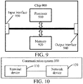
- FIG. 9 is a schematic diagram of structure of a chip according to an embodiment of the present application.
- the chip 900 shown in FIG. 9 includes a processor 910, which may call and run a computer program from a memory to implement the methods in the embodiments of the present application.
- the chip 900 may further include a memory 920.
- the processor 910 may call and run a computer program from the memory 920 to implement a method in an embodiment of the present application.
- the memory 920 may be a separate device independent of the processor 910, or may be integrated in the processor 910.
- the chip 900 may further include an input interface 930.
- the processor 910 may control the input interface 930 to communicate with another device or chip.
- the processor 710 may obtain information or data sent by another device or chip.
- the chip 900 may further include an output interface 940.
- the processor 910 may control the output interface 940 to communicate with another device or chip.
- the processor 710 may output information or data to another device or chip.
- the chip may be applied to the network device in the embodiments of the present application, and the chip may implement the corresponding flow implemented by the network device in the various methods in the embodiments of the present application, which will not be repeated here for brevity.
- the chip may be applied to the mobile terminal/terminal device in the embodiments of the present application, and the chip may implement the corresponding flow implemented by the mobile terminal/terminal device in the various methods in the embodiments of the present application, which will not be repeated here for brevity.
- the chip mentioned in the embodiments of the present application may also be referred to as a system-level chip, a system chip, a chip system, or a system chip on a chip, etc.
- FIG. 10 is a schematic block diagram of a communication system 100 according to an embodiment of the present application. As shown in FIG. 10 , the communication system 100 includes a terminal device 110 and a network device 120.
- the terminal device 110 may be configured to implement the corresponding functions implemented by the terminal device in the above-mentioned methods
- the network device 120 may be configured to implement the corresponding functions implemented by the network device in the above-mentioned methods, which will not be repeated here for brevity.
- the processor in the embodiments of the present application may be an integrated circuit chip with a capability for processing signals.
- various acts of the method embodiments described above may be completed through an integrated logic circuit of hardware in a processor or instructions in a form of software.
- the above processor may be a general purpose processor, a Digital Signal Processor (DSP), an Application Specific Integrated Circuit (ASIC), a Field Programmable Gate Array (FPGA), or another programmable logic device, a discrete gate or a transistor logic device, or a discrete hardware component.
- DSP Digital Signal Processor
- ASIC Application Specific Integrated Circuit
- FPGA Field Programmable Gate Array
- the processor may implement various methods, acts, and logic block diagrams disclosed in the embodiments of the present application.
- the general purpose processor may be a microprocessor or the processor may be any conventional processor or the like.
- the acts of the methods disclosed in connection with the embodiments of the present application may be directly embodied by execution of a hardware decoding processor, or by execution of a combination of hardware and software modules in a decoding processor.
- the software modules may be located in a storage medium mature in the field, such as a Random Access Memory, a flash memory, a Read-Only Memory, a Programmable Read-Only Memory, or an electrically erasable programmable memory, or a register.
- the storage medium is located in a memory, and a processor reads information in the memory and completes the acts of the above methods in combination with its hardware.
- the memory in the embodiments of the present application may be a transitory memory or a non-transitory memory, or may include both transitory and non-transitory memory.
- the non-transitory memory may be a Read-Only Memory (ROM), a Programmable ROM (PROM), an Erasable PROM (EPROM), an Electrically EPROM (EEPROM), or a flash memory.
- the transitory memory may be a Random Access Memory (RAM) which serves as an external cache.
- RAMs such as a Static RAM (SRAM), a Dynamic RAM (DRAM), a Synchronous DRAM (SDRAM), a Double Data Rate SDRAM (DDR SDRAM), an Enhanced SDRAM (ESDRAM), a Synchlink DRAM (SLDRAM), and a Direct Rambus RAM (DR RAM).
- SRAM Static RAM
- DRAM Dynamic RAM
- SDRAM Synchronous DRAM
- DDR SDRAM Double Data Rate SDRAM
- ESDRAM Enhanced SDRAM
- SLDRAM Synchlink DRAM
- DR RAM Direct Rambus RAM
- the foregoing memories are examples for illustration and should not be construed as limitations.
- the memory in the embodiments of the present application may be a Static RAM (SRAM), a Dynamic RAM (DRAM), a Synchronous DRAM (SDRAM), a Double Data Rate SDRAM (DDR SDRAM), an Enhanced SDRAM (ESDRAM), a Synch link DRAM (SLDRAM), a Direct Rambus RAM (DR RAM), or the like. That is, the memories in the embodiments of the present application are intended to include, but are not limited to, these and any other suitable types of memories.
- An embodiment of the present application further provides a computer readable storage medium configured to store a computer program.
- the computer readable storage medium may be applied to a network device in an embodiment of the present application, and the computer program enables a computer to perform the corresponding processes implemented by the network device in various methods according to the embodiments of the present application, which will not be repeated here for brevity.
- the computer readable storage medium may be applied to the mobile terminal/terminal device in the embodiments of the present application, and the computer program enables a computer to perform the corresponding processes implemented by the mobile terminal/terminal device in various methods according to the embodiments of the present application, which will not be repeated here for brevity.
- An embodiment of the present application further provides a computer program product, including computer program instructions.
- the computer program product may be applied to a network device in an embodiment of the present application, and the computer program instructions enable a computer to perform the corresponding processes implemented by the network device in various methods according to the embodiments of the present application, which will not be repeated here for brevity.
- the computer program product may be applied to the mobile terminal/terminal device in the embodiments of the present application, and the computer program instructions enable a computer to perform the corresponding processes implemented by the mobile terminal/terminal device in various methods according to the embodiments of the present application, which will not be repeated here for brevity.
- An embodiment of the present application further provides a computer program.
- the computer program may be applied to a network device in an embodiment of the present application.
- the computer program When the computer program is run on a computer, the computer is enabled to perform the corresponding processes implemented by the network device in various methods according to the embodiments of the present application, which will not be repeated here for brevity.
- the computer program may be applied to the mobile terminal/terminal device in the embodiments of the present application.
- the computer program When the computer program is run on a computer, the computer is enabled to perform the corresponding processes implemented by the mobile terminal/terminal device in various methods according to the embodiments of the present application, which will not be repeated here for brevity.
- the above units described as separate components may or may not be physically separated, and a component shown as the unit may be or may not be a physical unit; it may be located in one place, or may be distributed over multiple network units. Some or all of the units therein may be selected according to an actual requirement to achieve a purpose of the solution of the present embodiment.
- various functional units in various embodiments of the present application may all be integrated in one processing unit, or each unit may be separately presented as one unit, or two or more units may be integrated in one unit.
- the above-mentioned integrated units may be implemented in a form of hardware, or in a form of hardware plus software functional units.
- all or part of the acts for implementing the above method embodiments may be accomplished by hardware related to program instructions, and the aforementioned program may be stored in a computer readable storage medium.
- the program when executed, performs acts including the above method embodiments.
- the aforementioned storage media include: various media which may store program codes, such as a removable storage device, a Read Only Memory (ROM), a magnetic disk, or an optical disk, etc.
- the integrated units described above in the present application may be stored in a computer readable storage medium, if implemented in a form of software functional module and sold or used as a separate product.
- the technical solutions of the embodiments of the present application in essence, or the part contributing to the related art, may be embodied in the form of a software product, the computer software product is stored in one storage medium and includes several instructions to make an electronic device (which may be a mobile phone, a tablet, a digital telephone, a video telephone, a smart watch, etc.) perform all or part of the method described in various embodiments of the present application.
- the aforementioned storage medium includes various media which may store program codes, such as a removable storage device, a ROM, a magnetic disk, or an optical disk, etc.
Landscapes
- Engineering & Computer Science (AREA)
- Computer Networks & Wireless Communication (AREA)
- Signal Processing (AREA)
- Mobile Radio Communication Systems (AREA)
- Signal Processing For Digital Recording And Reproducing (AREA)
Abstract
Description
- Embodiments of the present application relate to electronic technology, and relate to but are not limited to a method and device for information processing, a storage medium, and a chip.
- In a frequency band below 6GHz, Specific Absorption Rate (SAR) is an index parameter for measuring the electromagnetic radiation intensity of the terminal to the human body. In order to avoid harm of electromagnetic radiation devices such as mobile phones to the human body, there are standards with strict requirements for the SAR value radiated by mobile phones, and the terminal should not exceed this limit. The SAR index is the average measured value of the terminal in a certain period of time. The higher the terminal transmission power, the higher the SAR value; or, the longer the uplink transmission time, the higher the SAR value.
- In a frequency band above 6GHz, the Maximum Permissible Emission (MPE) is an index parameter for measuring the electromagnetic radiation intensity of the terminal to human body. In order to avoid harm of electromagnetic radiation devices such as mobile phones to the human body, there are standards with strict requirements for the MPE value radiated by mobile phones, and the terminal should not exceed this limit. The MPE index is the average measured value of the power density of the terminal in a certain area within a certain period of time. The higher the terminal transmission power, the higher the MPE value.
- In order to meet SAR and MPE target indexes, a terminal often uses, for example, a range sensor to detect a distance between the terminal and a human body and performs power back-off to reduce the transmission power when the terminal gets close to the human body, so as to avoid the problem of SAR and MPE limit-exceeding.
- However, although the problem of SAR and MPE limit-exceeding is solved effectively by this method, it also comes with serious power loss.
- In view of this, embodiments of the present application provide a method and device for information processing, a storage medium, and a chip.
- Technical solutions of the embodiments of the present application are implemented as follows.
- In a first aspect, an embodiment of the present application provides a method for information processing, applied to a terminal, the method includes: determining multiple predefined uplink duty cycles corresponding to a first network device; determining multiple maximum uplink duty cycles that can be scheduled by a second network device, wherein there is a correspondence relation between the multiple maximum uplink duty cycles and the multiple predefined uplink duty cycles; and reporting the multiple maximum uplink duty cycles, wherein the multiple maximum uplink duty cycles are used for the second network device to select, according to a specific strategy, a referenced maximum uplink duty cycle from the multiple maximum uplink duty cycles when scheduling a transmission time of the terminal.
- In a second aspect, an embodiment of the present application further provides a method for information processing, applied to a network device, the method includes: acquiring multiple maximum uplink duty cycles reported by a terminal; selecting a referenced maximum uplink duty cycle from the multiple maximum uplink duty cycles according to a specific strategy; and scheduling a transmission time of the terminal according to the referenced maximum uplink duty cycle.
- In a third aspect, an embodiment of the present application provides a terminal device, including: a determining module, configured to determine multiple predefined uplink duty cycles corresponding to a first network device; and determine multiple maximum uplink duty cycles that can be scheduled by a second network device, wherein there is a correspondence relation between the multiple maximum uplink duty cycles and the multiple predefined uplink duty cycles; and a reporting module, configured to report the multiple maximum uplink duty cycles, wherein the multiple maximum uplink duty cycles are used for the second network device to select, according to a specific strategy, a referenced maximum uplink duty cycle from the multiple maximum uplink duty cycles when scheduling a transmission time of the terminal.
- In a fourth aspect, an embodiment of the present application further provides a network device, including: an acquiring module, configured to acquire multiple maximum uplink duty cycles reported by a terminal; a selecting module, configured to select a referenced maximum uplink duty cycle from the multiple maximum uplink duty cycles according to a specific strategy; and a scheduling module, configured to schedule a transmission time of the terminal according to the referenced maximum uplink duty cycle.
- In a fifth aspect, an embodiment of the present application provides a terminal device, including a first memory and a first processor, wherein the first memory stores a computer program which is runnable on the first processor, and the acts of the method for information processing of the embodiments of the present application are implemented when the first processor executes the computer program.
- In a sixth aspect, an embodiment of the present application provides a network device, including a second memory and a second processor, wherein the second memory stores a computer program which is runnable on the second processor, and the acts of the method for information processing of the embodiments of the present application are implemented when the second processor executes the computer program.
- In a seventh aspect, an embodiment of the present application provides a computer readable storage medium, on which a computer program is stored, wherein when the computer program is executed by a processor, acts in the methods for information processing of the embodiments of the present application are implemented.
- In an eight aspect, an embodiment of the present application provides a chip, including a processor configured for calling and running a computer program from a memory, to cause a device installed with the chip to perform the method for information processing of the terminal side in the embodiments of the present application; or, to cause a device installed with the chip to perform the method for information processing of the network device side in the embodiments of the present application.
- In the embodiments of the present application, a terminal reports multiple maximum uplink duty cycles that can be scheduled by a second network device, so that the second network device can adaptively select a referenced maximum uplink duty cycle from the multiple maximum uplink duty cycles according to uplink duty cycles actually scheduled by a first network device. Therefore, under different uplink duty cycle configurations of a first network device, a second network device can correspondingly adjust a referenced maximum uplink duty cycle capability, thus maximally ensuring that the terminal can meet SAR requirements while maintaining maximum power transmission.
-
-
FIG. 1 is a schematic diagram of a structure of communication architecture according to an embodiment of the present application. -
FIG. 2 is a schematic flowchart of an implementation of a method for information processing according to an embodiment of the present application. -
FIG. 3 is a schematic flowchart of another implementation of a method for information processing according to an embodiment of the present application. -
FIG. 4 is a schematic flowchart of yet another implementation of a method for information processing according to an embodiment of the present application. -
FIG. 5 is a schematic diagram of a time window according to an embodiment of the present application. -
FIG. 6A is a schematic diagram of a structure of a terminal device according to an embodiment of the present application. -
FIG. 6B is a schematic diagram of a structure of another terminal device according to an embodiment of the present application. -
FIG. 7A is a schematic diagram of a structure of a network device according to an embodiment of the present application. -
FIG. 7B is a schematic diagram of a structure of another network device according to an embodiment of the present application. -
FIG. 8 is a schematic diagram of a structure of a communication device according to an embodiment of the present application. -
FIG. 9 is a schematic diagram of a structure of a chip according to an embodiment of the present application. -
FIG. 10 is a schematic block diagram of a communication system according to an embodiment of the present application. - In order to make objects, technical solutions, and advantages of embodiments of the present application clearer, specific technical solutions of the present application will be described in further detail below with reference to accompanying drawings in the embodiments of the present application. Following embodiments are intended to illustrate the present application, but are not intended to limit the scope of the present application.
- Unless otherwise defined, all technical and scientific terms used herein have same meanings as those commonly understood by those skilled in the technical field of the present application. Terms used herein are only for the purpose of describing the embodiments of the present application, but are not intended to limit the present application.
- "Some embodiments" revolved in following description describe a subset of all possible embodiments, but it can be understood that "some embodiments" can be a same subset or different subsets of all possible embodiments, and can be combined with each other without conflict.
- It should be pointed out that the terms "first/second/third" in the embodiments of the present application are only for distinguishing similar objects, but do not represent a specific order for objects. Understandably, the "first/second/third" can be interchanged in a specific order or a sequence if allowed, so that the embodiments of the present application described here can be implemented in an order other than that illustrated or described here.
- An embodiment of the present application first provides communication architecture.
FIG. 1 is a schematic diagram of a structure of communication architecture according to an embodiment of the present application. As shown inFIG. 1 , the communication architecture at least includes aterminal 10, afirst network device 11, asecond network device 12, and acore network 13; wherein, theterminal 10 achieves communication under multiple connections by accessing thefirst network device 11 and thesecond network device 12; both thefirst network device 11 and thesecond network device 12 are connected to thecore network 13. - Of course, the terminal may also access three or more network devices simultaneously to achieve communication under multiple connections. In the process of implementation, terminals can be various types of devices with communication capabilities, such as cell phones, tablet computers, digital phones, video phones, smart watches, etc.
- An embodiment of the present application provides a method for information processing, wherein the method is applied to a terminal, and a function realized by the method may be achieved by a processor in the terminal for calling program codes. Of course, the program codes may be stored in a computer storage medium, it shows that the terminal at least includes a processor and a storage medium.
-
FIG. 2 is a schematic flowchart of an implementation of a method for information processing according to an embodiment of the present application. As shown inFIG. 2 , the method at least includes the followingacts 201 to 203. - In
Act 201, multiple predefined uplink duty cycles corresponding to a first network device are determined. - The uplink duty cycle refers to the percentage of uplink slots in the sum of uplink slots and downlink slots (i.e., the length of a time window) in the time window. For example, when a transmission time for transmitting signals by a terminal to a first network device within a time window is t1, and when a transmission time for transmitting signals by the first network device to the terminal within the time window is t2, then the uplink duty cycle within the time window is t1/(t1+t2).
- A first network device is usually a device which is first accessed and regarded as a primary cell by the terminal. For example, a first network device is a base station adopting Long Term Evolution (LTE) (hereinafter referred to as LTE base station), or is a base station adopting the 5th-Generation New radio (NR base station). When the first network device is an LTE base station, the terminal acquires multiple predefined uplink duty cycles corresponding to the LTE base station from pre-stored predefined uplink duty cycle information, or requests the LTE base station for the corresponding predefined uplink duty cycles. When the first network device is an NR base station, the way in which the terminal acquires multiple predefined duty cycles corresponding to the NR base station is similar to that in the above-mentioned approach, and will not be repeated here.
- In
Act 202, multiple maximum uplink duty cycles that can be scheduled by a second network device are determined, there is a correspondence relation between the multiple maximum uplink duty cycles and the multiple predefined uplink duty cycles. - In some embodiments, a predefined uplink duty cycle corresponds to a maximum uplink duty cycle. Multiple predefined uplink duty cycles are different, and a size relationship among multiple maximum uplink duty cycles is not limited.
- In an embodiment of the present application, a mode of a second network device may be identical or different from that of a first network device. The modes may be different, for example, the first network device is an LTE base station and the second network device is an NR base station, for another example, the first network device is an NR base station and the second network device is an LTE base station.
- For a terminal under multiple connections, in order to prevent the SAR value from exceeding the limit, the terminal needs to limit transmission powers and transmission times of the antennas corresponding to the first network device and the second network device respectively. In some embodiments, a terminal can determine each maximum uplink duty cycle according to the attribute parameter information of its own antenna (such as antenna position and antenna efficiency, etc.).
- Taking a first network device being an LTE base station and a second network device being an NR base station as an example, to simplify the operation, assuming that only a case where the terminal is at the maximum transmission power capability of the LTE antenna and the NR antenna is considered, the transmission times of the LTE antenna and the NR antenna need to meet certain constraints. As shown in Table 1 below, uplink duty cycles corresponding to an LTE base station are predefined multiple values (i.e. LTE predefined uplink duty cycle in Table 1), and maximum uplink duty cycles that can be scheduled by an NR base station are reported to the network as terminal capability.
- In Table 1, there is a correspondence relation between the parameters in the same row. For example, the maximum uplink duty cycle that can be scheduled by an NR base station corresponding to LTE predefined uplink duty cycle DutyLTE1 is maxULdutycycle-EN-DC1. The maximum uplink duty cycle that can be scheduled by an NR base station corresponding to LTE predefined uplink duty cycle DutyLTEn is maxULdutycycle-EN-DCn.
Table 1 LTE predefined uplink duty cycle NR base station schedulable maximum uplink duty cycle DutyLTE1 maxULdutycycle-EN- DC 1DutyLTE2 max ULdutycycle- EN - DC2 ... ... DutyLTEm maxULdutycycle-EN-DCm DutyLTEn maxULdutycycle-EN-DCn - In another example, when a first network device is an NR base station and a second network device is an LTE base station, as shown in Table 2 below, uplink duty cycles corresponding to an NR base station are predefined multiple values (i.e. NR predefined uplink duty cycle in Table 2), and maximum uplink duty cycles that can be scheduled by an LTE base station are reported to the network as terminal capability. Similarly, in Table 2, there is a correspondence relation between the parameters in the same row.
Table 2 NR predefined uplink duty cycle LTE base station schedulable Maximum uplink duty cycle DutyNR1 maxULdutycycle-NE- DC 1DutyNR2 maxULdutycycle-NE-DC2 ... ... DutyNRm maxULdutycycle-NE-DCm DutyNRn maxULdutycycle-NE-DCn - In
Act 203, the multiple maximum uplink duty cycles are reported, the multiple maximum uplink duty cycles are used for the second network device to select, according to a specific strategy, a reference maximum uplink duty cycle from the multiple maximum uplink duty cycles when scheduling a transmission time of the terminal. - Understandably, as a terminal reports multiple maximum uplink duty cycles, for the terminal and the second network device, both sides need to make clear which maximum uplink duty cycle is referenced when scheduling uplink duty cycles in the same arbitrary time window. The second network device needs to determine which one of the reported multiple maximum uplink duty cycles should be the upper limit for scheduling the uplink duty cycle of the terminal.
- In some embodiments, a second network device can schedule the transmission time of the terminal, so that the uplink duty cycle of the terminal within a time window is less than or equal to the referenced maximum uplink duty cycle.
- In the embodiments of the present application, the terminal reports multiple maximum uplink duty cycles that can be scheduled by the second network device, the multiple maximum uplink duty cycles are used for the second network device to, according to an uplink duty cycle actually scheduled by a first network device, adaptively select a referenced maximum uplink duty cycle from the multiple maximum uplink duty cycles reported by the terminal. Therefore, when a first network device uses different uplink duty cycle configurations, a second network device can correspondingly adjust the referenced maximum uplink duty cycle capability, thus maximally ensuring that the terminal can meet SAR requirements while maintaining maximum power transmission.
- An embodiment of the present application further provides another method for information processing.
FIG. 3 is a schematic flowchart of another implementation of a method for information processing according to an embodiment of the present application. As shown inFIG. 3 , the method at least includes the followingacts 301 to 308. - In
Act 301, a terminal determines multiple predefined uplink duty cycles corresponding to a first network device. - In
Act 302, the terminal device determines multiple maximum uplink duty cycles that can be scheduled by a second network device, there is a correspondence relation between the multiple maximum uplink duty cycles and the multiple predefined uplink duty cycles. - In
Act 303, the terminal reports the multiple maximum uplink duty cycles. - In some embodiments, a terminal reports multiple maximum uplink duty cycles to a first network device in the process of accessing the first network device with the first network device being a primary cell, wherein the first network device is used for informing a second network device of the multiple maximum uplink duty cycles. In this way, the terminal does not need to separately report this information to the second network device in the subsequent interaction, thus saving network resources and reducing the complexity of information interaction.
- In some embodiments, after acquiring information of the multiple maximum uplink duty cycles reported by a terminal, a first network device can directly forward the information to a second network device, or forward the information to a core network and the core network can send the information to the second network device.
- In
Act 304, a second network device acquires multiple maximum uplink duty cycles reported by the terminal. - In
Act 305, the second network device selects a referenced maximum uplink duty cycle from the multiple maximum uplink duty cycles according to a specific strategy in any time window. - During the implementation, the second network device can dynamically monitor the uplink duty cycle actually scheduled by the first network device, so as to adaptively adjust the current referenced maximum uplink duty cycle, and further ensure that the terminal can maintain the maximum transmission power capability to the maximum extent while meeting the SAR index. For example, the second network device periodically performs monitoring, and the length of each period is the length of a time window.
- In some embodiments, the second network device can implement
Act 305 by performingacts 405 to 409 in the following embodiment, so as to select the referenced maximum uplink duty cycle from the multiple maximum uplink duty cycles when scheduling the uplink duty cycles for the terminal in any time window. - In
Act 306, a second network device schedules the transmission time of the terminal according to the referenced maximum uplink duty cycle. - In
Act 307, the terminal acquires a first uplink duty cycle actually scheduled by the first network device for the terminal in the time window. - Here, there is no limitation on how the terminal acquires the first uplink duty cycle, and the terminal itself can count the first uplink duty cycle actually scheduled by the first network device for the terminal in each time window. Alternatively, the terminal may also receive the first uplink duty cycle information sent by the first network device.
- In some embodiments, the terminal can dynamically monitor the first uplink duty cycle actually scheduled by the first network device for the terminal. For example, the terminal performs monitoring periodically, and the length of each period is the length of the time window.
- In another embodiment, the first network device may transmit the first uplink duty cycle information to the terminal. There is no limitation on the transmission mode. The first network device can transmit actively or passively based on the request message sent by the terminal. For actively transmitting, the first network device can periodically transmit, or can inform the terminal when the first uplink duty cycle changes.
- It should be noted that in an embodiment of the present application, there is no limitation on the execution order of
Act 303 andAct 307, and the terminal can executeAct 303 first,Act 307 first, or Act 303 andAct 307 in parallel. - In addition, in an embodiment of the present application, a first uplink duty cycle and a second uplink duty cycle described below do not specifically refer to a specific uplink duty cycle, but a description in a general sense, where "first" and "second" are only used to distinguish that uplink duty cycles are scheduled by different network devices. The first uplink duty cycle is an uplink duty cycle actually scheduled by a first network device for the terminal. The second uplink duty cycle is an uplink duty cycle actually scheduled by a second network device for the terminal. Similarly, the following first sum does not specifically refer to a specific value.
- In some embodiments, a terminal determines a first sum of uplink slots actually scheduled by the first network device for the terminal within any aforementioned time window; the terminal determines a ratio of the first sum to a length of the time window as the first uplink duty cycle.
- In
Act 308, the terminal controls a transmission power according to a relationship between the first uplink duty cycle and the multiple predefined uplink duty cycles. - In an embodiment of the present application, a terminal can report information of multiple maximum uplink duty cycles, so that a second network device can schedule the transmission time of the terminal by using other uplink duty cycle capabilities when the uplink duty cycle actually scheduled by the first network device exceeds a certain value. In this way, the terminal does not have to carry out power back-off, and the power capability of the terminal can be effectively utilized.
- An embodiment of the present application further provides another method for information processing.
FIG. 4 is a schematic flowchart of yet another implementation of a method for information processing according to an embodiment of the present application. As shown inFIG. 4 , the method at least includes the followingacts 401 to 417. - In
Act 401, a terminal determines multiple predefined uplink duty cycles corresponding to a first network device. - In
Act 402, the terminal device determines multiple maximum uplink duty cycles that can be scheduled by a second network device, there is a correspondence relation between the multiple maximum uplink duty cycles and the multiple predefined uplink duty cycles. - In
Act 403, the terminal reports the multiple maximum uplink duty cycles. - In
Act 404, the second network device acquires information of multiple maximum uplink duty cycles reported by the terminal. - In
Act 405, the second network device acquires a first uplink duty cycle actually scheduled by the first network device for the terminal in any time window. - In some embodiments, a first network device can dynamically monitor an uplink duty cycle actually scheduled by the first network device itself for a terminal, and then send the monitoring result to a second network device. For example, the first network device periodically monitors an uplink duty cycle actually scheduled by the first network device itself for the terminal, and then sends the monitoring result obtained every time to the second network device, or sends the monitoring result to the second network device when the monitoring result changes. Wherein, a length of the monitoring period can be the length of a time window.
- In
Act 406, a second network device acquires multiple predefined uplink duty cycles of a first network device. - In some embodiments, the second network device can acquire information of multiple predefined uplink duty cycles of the first network device from the core network or the first network device. The second network device may also acquire the information of the multiple predefined uplink duty cycles from data pre-stored in the second network device itself.
- In
Act 407, a second network device determines a relationship between the first uplink duty cycle and the maximum value of the predefined uplink duty cycles; when the first uplink duty cycle is less than or equal to the maximum value,Act 408 is executed; otherwise,Act 411 is executed. - In
Act 408, the second network device selects a target predefined uplink duty cycle from the multiple predefined uplink duty cycles. - In some embodiments, a second network device can determine a difference value between the first uplink duty cycle and each predefined uplink duty cycle; the second network device determines a larger one of the predefined uplink duty cycles corresponding to two minimum difference values as a target predefined uplink duty cycle when each difference value is not zero; and when one of the determined difference values is zero, the second network device determines a predefined uplink duty cycle corresponding to the determined difference value of zero as the target predefined uplink duty cycle.
- For example, assuming that multiple predefined uplink duty cycles are 10%, 20%, 30% and 40% respectively. When the first uplink duty cycle is 20%, the target predefined uplink duty cycle is 20%; when the first uplink duty cycle is 25%, which is between 20% and 30%, the larger value, 30%, is taken as the target predefined uplink duty cycle.
- In
Act 409, the second network device determines the maximum uplink duty cycle corresponding to the target predefined uplink duty cycle as the referenced maximum uplink duty cycle. - For example, assume that the values of multiple predefined uplink duty cycles Dutylet1, Dutylet2, ..., Dutyletm and DutyLTEn increase in turn. Within a time window, when the second network device monitors that the uplink duty cycle actually scheduled by the LTE base station is between DutyLTE1 and DutyLTE2, it selects a larger one, i.e. DutyLTE2, as the target predefined uplink duty cycle; accordingly, the referenced maximum uplink duty cycle is DutyLTEnmaxULdutycycle-EN-DC2 en-dc2.
- Within a time window W, when the second network device monitors that the uplink duty cycle actually scheduled by the LTE base station is between DutyLTEm and DutyLTEn, it selects a larger one, i.e. DutyLTEn, as the target predefined uplink duty cycle; accordingly, the referenced maximum uplink duty cycle is DutyLTEnmaxULdutycycle-EN-DCn.
- In this way, it can be ensured that the corresponding selected maximum uplink duty cycle is more reliable, thus ensuring that the SAR of the terminal will not exceed the limit.
- In
Act 410, the second network device schedules the transmission time of the terminal according to the referenced maximum uplink duty cycle. - In
Act 411, the second network device performs one of the following acts when the first uplink duty cycle is greater than the maximum value of the multiple predefined uplink duty cycles: removing limitation on the maximum uplink duty cycle, keeping the current referenced maximum uplink duty cycle, or reducing the current referenced maximum uplink duty cycle. - It should be noted that
Act 405 to Act 409 are implementation acts for the second network device to determine the referenced maximum uplink duty cycle in any time window. In fact, for the terminal, it is necessary to perform the contents similar to those ofAct 405 to Act 409 within the same time window, so that the determined referenced maximum uplink duty cycle is consistent with the result determined by the second network device. - In an embodiment of the present application, the execution order of
Act 403 andAct 412 is not limited, and the terminal can executeAct 403 first, or can executeAct 412 first, or Act 403 and Act 412 can be executed in parallel, that is, the terminal side and the second network device side can execute the acts of determining the referenced maximum uplink duty cycle in parallel. - In
Act 412, a terminal acquires a first uplink duty cycle actually scheduled by the first network device for the terminal in the time window. - In
Act 413, the terminal determines a relationship between the first uplink duty cycle and the maximum value of the multiple predefined uplink duty cycles; when the first uplink duty cycle is greater than the maximum value,Act 414 is executed; otherwise,Act 415 is executed. - Understandably, after obtaining the first uplink duty cycle, the terminal first determines the relationship between the first uplink duty cycle and the maximum value, and only executes
Act 415 when the first uplink duty cycle is less than or equal to the maximum value. In such a way, when the first uplink duty cycle is greater than the maximum value, power back or power level back can be performed more timely, thereby minimizing the harm of electromagnetic radiation to human body. - In
Act 414, the terminal performs power back-off or power level back-off. - Understandably, when the terminal performs power back-off or power level back-off, it may not be controlled by the network side. That is to say, when the terminal detects that a condition for reducing the transmission power is met, it actively performs power back-off or power level back-off without waiting for indication from the network side. In this way, the transmission power can be reduced faster, thus minimizing the harm of electromagnetic radiation to human body.
- In
Act 415, the terminal determines the referenced maximum uplink duty cycle from the multiple maximum uplink duty cycles according to the specific strategy. - When implementing
Act 415, the terminal can first determine a difference value between the first uplink duty cycle and each predefined uplink duty cycle; determine a larger one of the predefined uplink duty cycles corresponding to two minimum difference values as a target predefined uplink duty cycle when each difference value is not zero; and determine the maximum uplink duty cycle corresponding to the target predefined uplink duty cycle as the referenced maximum uplink duty cycle. - In some embodiments, when one of the determined difference values is zero, a terminal determines the predefined uplink duty cycle corresponding to the determined difference value of zero as the target predefined uplink duty cycle.
- Understandably, in a same time window, the terminal and the second network device need to determine the referenced maximum uplink duty cycle based on the same or similar specific strategy. Only in this way, the results in two choices can just be consistent, thus avoiding the problem of SAR limit-exceeding caused by misoperation of a terminal or the problem of power loss caused by unnecessary power back-off performed by the terminal.
- For example, the referenced maximum uplink duty cycles determined by the terminal side and the second network device side are 10% and 20% respectively, while the uplink duty cycle actually scheduled by the second network device detected by the terminal is 15%. Since 15% is greater than 20%, the terminal will perform power back-off at this time. But in fact, the referenced maximum uplink duty cycle is 20% when the second network device actually schedules the uplink duty cycle of the terminal, so if the terminal continues to maintain the current transmission power, it can be ensured that the SAR does not exceed the limit. However, the terminal also reduces the transmission power at the same time, which will lead to unnecessary power loss.
- For another example, the referenced maximum uplink duty cycles determined by the terminal side and the second network device side are 30% and 20% respectively. Then, if the terminal detects that the uplink duty cycle actually scheduled by the second network device is 25%, which is less than 30%, the terminal will continue to maintain the current transmission power at this time. While in fact, the referenced maximum uplink duty cycle is 20% when the second network device actually schedules the uplink duty cycle of the terminal. Therefore, the terminal should perform power back-off or power level back-off, otherwise the SAR limit-exceeding will be caused.
- In some embodiments, the terminal may also send a request message to the second network device to request to know the current maximum uplink referenced by the second network device, but this way is at the cost of sacrificing channel resources and increasing communication complexity.
- In
Act 416, a terminal acquires a second uplink duty cycle actually scheduled by the second network device for the terminal in the time window. - Here, there is no limitation on how the terminal acquires the second uplink duty cycle, and the terminal itself can count the second uplink duty cycle actually scheduled by the second network device for the terminal in each time window. Alternatively, the terminal may also receive the second uplink duty cycle information sent by the second network device.
- In some embodiments, the terminal can dynamically monitor the second uplink duty cycle actually scheduled by the second network device for the terminal. For example, the terminal performs monitoring periodically, and the length of each period is the length of the time window.
- In another embodiment, the second network device may transmit the second uplink duty cycle information to the terminal. There is no limitation on the transmission mode. The second network device can transmit actively or passively based on the request message sent by the terminal. For actively transmitting, the second network device can periodically transmit, or can inform the terminal when the second uplink duty cycle changes.
- In
Act 417, a terminal performs power back-off or power level back-off when the second uplink duty cycle exceeds the referenced maximum uplink duty cycle. - Understandably, a terminal performs power back-off or power level back-off when the second uplink duty cycle exceeds the referenced maximum uplink duty cycle, so that it can be ensured that the SAR of the terminal will not exceed the limit, thereby ensuring that human health is not harmed.
- In some embodiments, when the second uplink duty cycle does not exceed the referenced maximum uplink duty cycle, the terminal maintains the current power or maintains the current power level.
- An embodiment of the present application further provides another method for information processing, which at least includes the following acts 501 to 508.
- In Act 501, a terminal determines multiple predefined uplink duty cycles corresponding to a first network device.
- In Act 502, the terminal acquires attribute parameter information of an antenna.
- In some embodiments, the attribute parameter information may include antenna position and antenna efficiency. Assuming that an antenna connected to a first network device in a terminal is a first antenna (such as an LTE antenna), and an antenna connected to a second network device is a second antenna (such as an NR antenna), the antenna position includes a relative position of the first antenna and the second antenna, and the antenna position may also include a position of the first antenna and a position of the second antenna.
- In Act 503, the terminal determines each of the maximum uplink duty cycles according to the attribute parameter information, wherein there is a one-to-one correspondence relation between the maximum uplink duty cycles and the predefined uplink duty cycles.
- In Act 504, the terminal reports the determined multiple maximum uplink duty cycles to the first network device in a process of accessing the first network device with the first network device being as the primary cell.
- In Act 505, the first network device informs the second network device of the multiple maximum uplink duty cycles.
- For example, the first network device directly sends the multiple maximum uplink duty cycles to the second network device, or the first network device sends the multiple maximum uplink duty cycles to a core network, so that the second network device can acquire the multiple maximum uplink duty cycles through a communication link with the core network. Understandably, both the first network device and the second network device are connected to the core network, so that the terminal reports the multiple maximum uplink duty cycles when firstly accessing the first network device, and information of the reported multiple maximum uplink duty cycles is stored in the core network, so that the second network device acquires the information of the multiple maximum uplink duty cycles faster, thus minimizing the harm of electromagnetic radiation to human body.
- In Act 506, the second network device acquires the multiple maximum uplink duty cycles reported by the terminal.
- In Act 507, the second network device adaptively selects a referenced maximum uplink duty cycle from the multiple maximum uplink duty cycles according to a specific strategy.
- The second network device can achieve Act 507 through
Act 405 to Act 409 in the above embodiment. After determining multiple maximum uplink duty cycles, in addition to reporting the information, the terminal needs to perform the contents similar to those ofAct 405 to Act 40 9 in a same time window, so that the determined referenced maximum uplink duty cycle is consistent with the result determined by the second network device. Details will not be repeated here for brevity. - In Act 508, the second network device schedules the transmission time of the terminal according to the referenced maximum uplink duty cycle.
- It should be noted that in some embodiments, for the terminal and the second network device, it may also be the case that only one party of the two determines the maximum uplink duty cycle referenced by the second network device, and after one party of the two determines the referenced maximum uplink duty cycle in a certain time window, the information can be notified to the other party. For example, in a time window, the terminal determines the referenced maximum uplink duty cycle from the multiple maximum uplink duty cycles according to the specific strategy, and informs the second network device which maximum uplink duty cycle is referenced in this time window. Or, after determining the referenced maximum uplink duty cycle, the second network device informs the terminal which maximum uplink duty cycle is referenced by the second network device when scheduling its transmission time in the time window.
- From the point of view of reducing terminal radiation time, the terminal capability of maximum uplink slot duty cycle (maxULdutycycle) is introduced, that is, the maximum uplink duty cycle, which can be supported when SAR or MPE is met in a certain frequency band, reported by the terminal to the network. When the uplink duty cycle scheduled by the network exceeds this capability, the terminal adopts power back-off to reduce SAR and MPE values.
- For EN-DC (LTE and NR dual connection) terminals, solutions generally considered are usually that a terminal reports a pair of maximum uplink duty cycle capacities that can be scheduled by LTE and NR networks respectively at the same time, or reports one NR uplink duty cycle according to an LTE uplink duty cycle, etc. The disadvantage of this solution lies in that, although it can be ensured that the SARs of the EN-DC terminal working in LTE and NR at the same time do not exceed the limit, the terminal needs to perform power back-off when one uplink duty cycle of LTE mode or NR mode exceeds the reported capability value. In fact, when the uplink duty cycle of one mode exceeds the reported capacity value, the terminal can still meet the requirement that SAR does not exceed the limit by reducing the uplink duty cycle of another mode.
- Based on this, an exemplary application of an embodiment of the present application in an actual application scenario will be explained in the following.
- For a Multi-connection terminal (taking EN-DC as an example below), transmission power or transmission time of the terminal can be limited so as to meet the requirement that the SAR value does not exceed the limit. In the following, the scheduling mechanism of the uplink transmission time of the EN-DC terminal is described from the angle of limiting the transmission time, the transmission time is maximized while meeting the SAR index.
- In an EN-DC network, the terminal needs to access an LTE network first and take the network as a primary cell. In this process, the terminal reports the maximum uplink duty cycle capacity of NR to an LTE primary cell, and then the LTE network further configures an NR secondary cell.
- In order to satisfy SAR, the terminal needs to limit transmission powers and transmission times of LTE and NR respectively. To simplify the operation, in the following embodiment, only an application scenario where, for a terminal, both LTE and NR are at the maximum transmission power capability is considered, then the transmission times of LTE and NR need to meet certain restrictions. As shown in Table 3 below, the uplink duty cycles of LTE are predefined multiple values, and the NR schedulable maximum uplink duty cycles is reported to the network as the terminal capability.
Table 3 LTE predefined uplink duty cycle NR schedulable maximum uplink slot duty cycle capability DutyLTE1 maxULdutycycle-EN- DC 1DutyLTE2 maxULdutycycle-EN-DC2 ... ... DutyLTEm maxULdutycycle-EN-DCm DutyLTEn maxULdutycycle-EN-DCn - Since the terminal reported multiple maximum uplink duty cycles of NR, for NR network and the terminal, it is necessary to clarify which maximum uplink duty cycle capability should be followed (that is, referenced) when scheduling uplink duty cycles in any time window W. The schematic diagram of one time window W is shown in
FIG 5 . For NR side, one time window W includes time units S1 to Sk+2, where the time unit can be a slot, symbol or subframe, etc. For LTE side, its time window W is aligned with that of the NR side. - Taking a time window W as an example, a method of selecting maximum uplink capacity of NR will be introduced below, where it is assumed that DutyLTE1 < DutyLTE2 < ... < DutyLTEm < DutyLTEn.
- Within the time window W, when the terminal and the network detect that the uplink duty cycle actually scheduled of LTE is between DutyLTE1 and DutyLTE2, it is considered that the uplink duty cycle of LTE is the larger one, i.e., DutyLTE2, and the corresponding NR schedulable maximum uplink duty cycle capacity is maxULdutycycle-EN-DC2 en-DC2. When the uplink duty cycle actually scheduled of NR exceeds this capacity, the terminal needs to perform power back-off or power level back-off. Of course, when the uplink duty cycle actually scheduled of NR does not exceed this capacity, the terminal continues to maintain the current transmission power.
- Within the time window W, when the terminal and the network detect that the uplink duty cycle actually scheduled of LTE is between DutyLTEm and DutyLTEn, it is considered that the uplink duty cycle of LTE is the larger one, i.e. DutyLTEn, and the corresponding NR schedulable maximum uplink duty cycle capacity is maxULdutycycle-EN-DCn. When the uplink duty cycle actually scheduled of NR exceeds this capacity, the terminal needs to perform power back-off or power level back-off. Of course, when the uplink duty cycle actually scheduled of NR does not exceed this capacity, the terminal continues to maintain the current transmission power.
- Within the time window W, when the uplink duty cycle actually scheduled of LTE exceeds DutyLTEn (that is, the predefined maximum uplink duty cycle of LTE), the terminal needs to perform power back-off or power level back-off.
- From the above example, it can be seen that the uplink duty cycle of LTE needs to round up to a value which is closest to the predefined uplink duty cycle, and the corresponding maximum uplink duty cycle capability of NR is acquired, and the maximum uplink duty cycle capability of NR is not always fixed, but changes with the uplink duty cycle actually scheduled of LTE within the time window W.
- By reporting a set of maximum uplink capacities of NR, the terminal can correspondingly adjust the maximum uplink capacity of NR under different LTE uplink configurations, and keep the maximum power transmission.
- Through the implementation of the above technical solution, it can be ensured that the terminal can adjust the maximum uplink duty cycle capability of NR by adapting to the uplink duty cycle of LTE, thus ensuring, to the utmost extent, that the EN-DC terminal can meet the SAR while maintaining the maximum transmission power capability.
- In an embodiment of the present application, a scheduling method (i.e., information processing method) for transmission time of a multi-connection terminal is provided. In this scheduling method, the terminal reports, according to information of the predefined multiple uplink duty cycles of an A-mode base station (that is, the first network device), information of the multiple uplink duty cycle capabilities (such as information of maximum uplink duty cycle) of a B-mode base station (i.e., the second network device) corresponding to information of each predefined uplink duty cycle. B-mode base station performs scheduling according to this set of capability information. The terminal decides to adopt the uplink duty cycle capability corresponding to the B-mode base station by monitoring information of the uplink duty cycles scheduled by the A-mode base station.
- In an embodiment of the present application, key technical features involved include the following.
- (1) A terminal reports information of multiple uplink duty cycle capabilities that can be scheduled by a B-mode base station, and all uplink duty cycle capabilities of this group of capability information corresponds to the uplink duty cycles of an A-mode base station respectively.
- (2) The terminal decides which corresponding schedulable proportion capability in the B-mode base station capability information group previously reported is adopted by monitoring the uplink duty cycles actually scheduled by the A-mode base station.
- (3) The B-mode base station decides which duty cycle capacity in the capacity information group previously reported by the terminal is adopted by acquiring the uplink duty cycles actually scheduled by the A-mode base station for the terminal.
- Understandably, the capability information reported by the terminal to the network is generally a capability, which only corresponds to the uplink configuration of a certain A-mode base station. When the uplink duty cycle of either the A-mode base station or the B-mode base station exceeds the terminal capability, power back-off needs to be performed on the transmission power of the terminal. However, in an embodiment of the present application, the terminal reports multiple capacity values (such as the maximum uplink duty cycles), that is, when an uplink duty cycle actually scheduled by the A-mode base station exceeds a certain value, the terminal can adopt other uplink duty cycle capacities for the B-mode base station without having to perform power back-off. In this way, the power capacity of the terminal can be effectively utilized.
- In an embodiment of the application, the terminal reports information of multiple uplink duty cycle capabilities that can be scheduled by the B-mode base station, wherein information of each duty cycle capability corresponds to an uplink duty cycle of the A-mode base station. The base station and the terminal determine an adopted uplink duty cycle capability of the B-mode base station by dynamically monitoring the uplink duty cycles actually scheduled by the A-mode base station.
- Based on the foregoing embodiments, an embodiment of the present application provides a terminal device, the terminal device includes various modules and various units included in the modules, which can be achieved by a processor in the terminal, of course, they may also be implemented by a specific logic circuit. In an implementation process, the processor may be a central processing unit (CPU), a microprocessor (MPU), a digital signal processor (DSP) or a field programmable gate array (FPGA), etc.
-
FIG. 6A is a schematic diagram of a structure of a terminal device according to an embodiment of the present application. As shown inFIG. 4 , aterminal device 600 includes a determiningmodule 601 and areporting module 602. - The determining module is configured to determine multiple predefined uplink duty cycles corresponding to a first network device; and determine multiple maximum uplink duty cycles that can be scheduled by a second network device, there is a correspondence relation between the multiple maximum uplink duty cycles and the multiple predefined uplink duty cycles.
- The
reporting module 602 is configured to report the multiple maximum uplink duty cycles, the multiple maximum uplink duty cycles are used for the second network device to select therefrom, according to a specific strategy, a referenced maximum uplink duty cycle when scheduling a transmission time of the terminal. - In some embodiments, as shown in
FIG. 6B , theterminal device 600 further includes apower control module 603. The determiningmodule 601 is further configured to acquire a first uplink duty cycle actually scheduled by the first network device for the terminal in any time window; and thepower control module 603 is configured to control the transmission power according to a relationship between the first uplink duty cycle and the multiple predefined uplink duty cycles. - In some embodiments, the
power control module 603 is configured to determine a relationship between the first uplink duty cycle and a maximum value of the multiple predefined uplink duty cycles; and perform power back-off or power level back-off when the first uplink duty cycle is greater than the maximum value. - In some embodiments, the determining
module 601 is further configured to determine the referenced maximum uplink duty cycle from the multiple maximum uplink duty cycles according to the specific strategy when the first uplink duty cycle is less than or equal to the maximum value. - In some embodiments, the determining
module 601 is configured to determine a difference value between the first uplink duty cycle and each predefined uplink duty cycle; determine a larger one of the predefined uplink duty cycles corresponding to two minimum difference values as a target predefined uplink duty cycle when each difference value is not zero; and determine the maximum uplink duty cycle corresponding to the target predefined uplink duty cycle as the referenced maximum uplink duty cycle. - In some embodiments, the determining
module 601 is further configured to determine a predefined uplink duty cycle corresponding to zero as the target predefined uplink duty cycle when one of the determined difference values is zero. - In some embodiments, the
power control module 603 is further configured to acquire a second uplink duty cycle actually scheduled by the second network device for the terminal in the time window; and perform power back-off or power level back-off when the second uplink duty cycle exceeds the referenced maximum uplink duty cycle. - In some embodiments, the determining
module 601 is configured to determine a first sum of uplink slots actually scheduled by the first network device for the terminal within the time window; and determine a ratio of the first sum to a length of the time window as the first uplink duty cycle. - In some embodiments, the
reporting module 602 is configured to report the multiple maximum uplink duty cycles to the first network device in a process of accessing with the first network device being a primary cell, wherein the first network device is used for informing the second network device of the multiple maximum uplink duty cycles. - In some embodiments, the determining
module 601 is configured to acquire attribute parameter information of an antenna; and determine each of the maximum uplink duty cycles according to the attribute parameter information, wherein there is a one-to-one correspondence relation between the maximum uplink duty cycles and the predefined uplink duty cycles. - An embodiment of the present application provides a network device.
FIG. 7A is a schematic diagram of a structure of a network device according to an embodiment of the present application. As shown inFIG. 7A , anetwork device 700 includes an acquiringmodule 701, a selectingmodule 702, and ascheduling module 703. - The acquiring
module 701 is configured to acquire multiple maximum uplink duty cycles reported by a terminal. - The selecting
module 702 is configured to adaptively select a referenced maximum uplink duty cycle from the multiple maximum uplink duty cycles according to a specific strategy. - The
scheduling module 703 is configured to schedule a transmission time of the terminal according to the referenced maximum uplink duty cycle. - In some embodiments, the selecting
module 702 is configured to acquire a first uplink duty cycle actually scheduled by a first network device for the terminal in any time window; acquire multiple predefined uplink duty cycles of the first network device; select a target predefined uplink duty cycle from the multiple predefined uplink duty cycles when the first uplink duty cycle is less than or equal to the maximum value of the multiple predefined uplink duty cycles; and determine the maximum uplink duty cycle corresponding to the target predefined uplink duty cycle as the referenced maximum uplink duty cycle. - In some embodiments, the selecting
module 702 is configured to determine a difference value between the first uplink duty cycle and each predefined uplink duty cycle; determine a larger one of the predefined uplink duty cycles corresponding to two minimum difference values as a target predefined uplink duty cycle when each difference value is not zero; determine the predefined uplink duty cycle corresponding to zero as the target predefined uplink duty cycle when one of the determined difference values is zero. - In some embodiments, as shown in
FIG. 7B , anetwork device 700 further includes acontrol module 704, configured to perform one of the following acts when the first uplink duty cycle is greater than the maximum value of the multiple predefined uplink duty cycles: removing limitation on the maximum uplink duty cycle, keeping the current referenced maximum uplink duty cycle, or reducing the current referenced maximum uplink duty cycle. - The description of the above device embodiment is similar to the description of the above method embodiment, and has similar beneficial effects as the method embodiment. For technical details not disclosed in the device embodiments of the present application, please refer to the description of the method embodiments of the present application to understand.
- It should be noted that in the embodiments of the present application, if the above method for processing information is implemented in a form of a software function module, and when sold or used as an independent product, it may also be stored in a computer readable storage medium. Based on this understanding, the technical solutions of the embodiments of the present application, in essence, or the part contributing to the related art, may be embodied in the form of a software product, the computer software product is stored in one storage medium and includes several instructions to make an electronic device (which may be a mobile phone, a tablet, a digital telephone, a video telephone, a smart watch, etc.) perform all or part of the method described in various embodiments of the present application. And the aforementioned storage medium includes various media which may store program codes, such as a U disk, a mobile hard disk, a Read Only Memory (ROM), a magnetic disk or an optical disk. Thus, the embodiments of the present application are not limited to any specific combination of hardware and software.
-
FIG. 8 is a schematic diagram of structure of acommunication device 800 according to an embodiment of the present application. Thecommunication device 800 shown inFIG. 8 includes aprocessor 810, which may call and run a computer program from a memory to implement the methods in the embodiments of the present application. - Optionally, as shown in
FIG. 8 , thecommunication device 800 may further include amemory 820. Herein, theprocessor 810 may call and run a computer program from thememory 820 to implement a method in an embodiment of the present application. - Herein, the
memory 820 may be a separate device independent of theprocessor 810, or may be integrated in theprocessor 810. - Optionally, as shown in
FIG. 8 , thecommunication device 800 may further include atransceiver 830, and theprocessor 810 may control thetransceiver 830 to communicate with another device. Specifically, the transceiver 630 may send information or data to another device or receive information or data sent by another device. - Herein, the
transceiver 830 may include a transmitter and a receiver. Thetransceiver 830 may further include antennas, a quantity of which may be one or more. - Optionally, the
communication device 800 may be specifically the network device according to the embodiments of the present application, and thecommunication device 800 may implement the corresponding processes implemented by the network device in various methods in the embodiments of the present application, which will not be repeated here for brevity. - Optionally, the
communication device 800 may be specifically the mobile terminal/terminal device according to the embodiments of the present application, and thecommunication device 800 may implement the corresponding processes implemented by the mobile terminal/terminal device in various methods in the embodiments of the present application, which will not be repeated here for brevity. -
FIG. 9 is a schematic diagram of structure of a chip according to an embodiment of the present application. Thechip 900 shown inFIG. 9 includes aprocessor 910, which may call and run a computer program from a memory to implement the methods in the embodiments of the present application. - Optionally, as shown in
FIG. 9 , thechip 900 may further include amemory 920. Herein, theprocessor 910 may call and run a computer program from thememory 920 to implement a method in an embodiment of the present application. - Herein, the
memory 920 may be a separate device independent of theprocessor 910, or may be integrated in theprocessor 910. - Optionally, the
chip 900 may further include aninput interface 930. Herein, theprocessor 910 may control theinput interface 930 to communicate with another device or chip. Specifically, the processor 710 may obtain information or data sent by another device or chip. - Optionally, the
chip 900 may further include anoutput interface 940. Herein, theprocessor 910 may control theoutput interface 940 to communicate with another device or chip. Specifically, the processor 710 may output information or data to another device or chip. - Optionally, the chip may be applied to the network device in the embodiments of the present application, and the chip may implement the corresponding flow implemented by the network device in the various methods in the embodiments of the present application, which will not be repeated here for brevity.
- Optionally, the chip may be applied to the mobile terminal/terminal device in the embodiments of the present application, and the chip may implement the corresponding flow implemented by the mobile terminal/terminal device in the various methods in the embodiments of the present application, which will not be repeated here for brevity.
- It should be understood that the chip mentioned in the embodiments of the present application may also be referred to as a system-level chip, a system chip, a chip system, or a system chip on a chip, etc.
-
FIG. 10 is a schematic block diagram of acommunication system 100 according to an embodiment of the present application. As shown inFIG. 10 , thecommunication system 100 includes aterminal device 110 and anetwork device 120. - The
terminal device 110 may be configured to implement the corresponding functions implemented by the terminal device in the above-mentioned methods, and thenetwork device 120 may be configured to implement the corresponding functions implemented by the network device in the above-mentioned methods, which will not be repeated here for brevity. - It should be understood that the processor in the embodiments of the present application may be an integrated circuit chip with a capability for processing signals. In an implementation process, various acts of the method embodiments described above may be completed through an integrated logic circuit of hardware in a processor or instructions in a form of software. The above processor may be a general purpose processor, a Digital Signal Processor (DSP), an Application Specific Integrated Circuit (ASIC), a Field Programmable Gate Array (FPGA), or another programmable logic device, a discrete gate or a transistor logic device, or a discrete hardware component. The processor may implement various methods, acts, and logic block diagrams disclosed in the embodiments of the present application. The general purpose processor may be a microprocessor or the processor may be any conventional processor or the like. The acts of the methods disclosed in connection with the embodiments of the present application may be directly embodied by execution of a hardware decoding processor, or by execution of a combination of hardware and software modules in a decoding processor. The software modules may be located in a storage medium mature in the field, such as a Random Access Memory, a flash memory, a Read-Only Memory, a Programmable Read-Only Memory, or an electrically erasable programmable memory, or a register. The storage medium is located in a memory, and a processor reads information in the memory and completes the acts of the above methods in combination with its hardware.
- It should be understood that the memory in the embodiments of the present application may be a transitory memory or a non-transitory memory, or may include both transitory and non-transitory memory. The non-transitory memory may be a Read-Only Memory (ROM), a Programmable ROM (PROM), an Erasable PROM (EPROM), an Electrically EPROM (EEPROM), or a flash memory. The transitory memory may be a Random Access Memory (RAM) which serves as an external cache. As an example, but not as a restriction, many forms of RAMs are available, such as a Static RAM (SRAM), a Dynamic RAM (DRAM), a Synchronous DRAM (SDRAM), a Double Data Rate SDRAM (DDR SDRAM), an Enhanced SDRAM (ESDRAM), a Synchlink DRAM (SLDRAM), and a Direct Rambus RAM (DR RAM). It should be noted that the memories of the systems and methods described herein are intended to include, but are not limited to, these and any other suitable types of memories.
- It should be understood that, the foregoing memories are examples for illustration and should not be construed as limitations. For example, the memory in the embodiments of the present application may be a Static RAM (SRAM), a Dynamic RAM (DRAM), a Synchronous DRAM (SDRAM), a Double Data Rate SDRAM (DDR SDRAM), an Enhanced SDRAM (ESDRAM), a Synch link DRAM (SLDRAM), a Direct Rambus RAM (DR RAM), or the like. That is, the memories in the embodiments of the present application are intended to include, but are not limited to, these and any other suitable types of memories.
- An embodiment of the present application further provides a computer readable storage medium configured to store a computer program.
- Optionally, the computer readable storage medium may be applied to a network device in an embodiment of the present application, and the computer program enables a computer to perform the corresponding processes implemented by the network device in various methods according to the embodiments of the present application, which will not be repeated here for brevity.
- Optionally, the computer readable storage medium may be applied to the mobile terminal/terminal device in the embodiments of the present application, and the computer program enables a computer to perform the corresponding processes implemented by the mobile terminal/terminal device in various methods according to the embodiments of the present application, which will not be repeated here for brevity.
- An embodiment of the present application further provides a computer program product, including computer program instructions.
- Optionally, the computer program product may be applied to a network device in an embodiment of the present application, and the computer program instructions enable a computer to perform the corresponding processes implemented by the network device in various methods according to the embodiments of the present application, which will not be repeated here for brevity.
- Optionally, the computer program product may be applied to the mobile terminal/terminal device in the embodiments of the present application, and the computer program instructions enable a computer to perform the corresponding processes implemented by the mobile terminal/terminal device in various methods according to the embodiments of the present application, which will not be repeated here for brevity.
- An embodiment of the present application further provides a computer program.
- Optionally, the computer program may be applied to a network device in an embodiment of the present application. When the computer program is run on a computer, the computer is enabled to perform the corresponding processes implemented by the network device in various methods according to the embodiments of the present application, which will not be repeated here for brevity.
- Optionally, the computer program may be applied to the mobile terminal/terminal device in the embodiments of the present application. When the computer program is run on a computer, the computer is enabled to perform the corresponding processes implemented by the mobile terminal/terminal device in various methods according to the embodiments of the present application, which will not be repeated here for brevity.
- It should be pointed out here that the descriptions of the above storage medium, computer program, chip and the device embodiment are similar to the description of the above method embodiments, and they have similar beneficial effects as the method embodiments. For technical details not disclosed in the storage medium and the device embodiment of the present application, please refer to the description of the method embodiments of the present application to understand.
- It should be understood that "one embodiment" or "an embodiment" mentioned throughout the specification means that a particular feature, a structure, or a characteristic related to the embodiments is included in at least one embodiment of the present application. Thus, "in one embodiment" or "in an embodiment" in the specification may not definitely refer to the same embodiment. In addition, the particular features, structures, or characteristics may be combined in any suitable manner in one or more embodiments. It should be understood that in various embodiments of the present application, sequence numbers of the various processes do not imply an order of execution of the various processes, which should be determined by their functions and internal logics, but should not constitute any limitation on implementation processes of the embodiments of the present application. The above-mentioned serial numbers of the embodiments of the present application are only for description, and do not represent superiority and inferiority of the embodiments.
- It should be noted that in the present application, the terms "include", "contain" or any other variations thereof are intended to cover a non-exclusive inclusion, such that a process, method, article, or device that includes a list of elements includes not only those elements but also other elements not expressly listed, or further includes elements inherent to such process, method, article, or device. An element defined by a statement "include one" does not exclude presence of additional identical elements in the process, method, article or system that includes the element, without more limitations.
- In several embodiments provided by the present application, it should be understood that disclosed devices and methods may be implemented in another mode. The device embodiments described above are only illustrative, for example, a partition of units is only a logical function partition, and there may be other partition manners in actual implementation. For example, multiple units or components may be combined or integrated into another system, or some features may be ignored or not executed. In addition, mutual coupling or direct coupling or communication connection between various components shown or discussed may be indirect coupling or communication connection between devices or units through some interfaces, and may be electrical, mechanical or in other forms.
- The above units described as separate components may or may not be physically separated, and a component shown as the unit may be or may not be a physical unit; it may be located in one place, or may be distributed over multiple network units. Some or all of the units therein may be selected according to an actual requirement to achieve a purpose of the solution of the present embodiment.
- In addition, various functional units in various embodiments of the present application may all be integrated in one processing unit, or each unit may be separately presented as one unit, or two or more units may be integrated in one unit. The above-mentioned integrated units may be implemented in a form of hardware, or in a form of hardware plus software functional units.
- One ordinary skilled in the art can understand that, all or part of the acts for implementing the above method embodiments may be accomplished by hardware related to program instructions, and the aforementioned program may be stored in a computer readable storage medium. The program, when executed, performs acts including the above method embodiments. And the aforementioned storage media include: various media which may store program codes, such as a removable storage device, a Read Only Memory (ROM), a magnetic disk, or an optical disk, etc.
- Alternatively, the integrated units described above in the present application may be stored in a computer readable storage medium, if implemented in a form of software functional module and sold or used as a separate product. Based on this understanding, the technical solutions of the embodiments of the present application, in essence, or the part contributing to the related art, may be embodied in the form of a software product, the computer software product is stored in one storage medium and includes several instructions to make an electronic device (which may be a mobile phone, a tablet, a digital telephone, a video telephone, a smart watch, etc.) perform all or part of the method described in various embodiments of the present application. And the aforementioned storage medium includes various media which may store program codes, such as a removable storage device, a ROM, a magnetic disk, or an optical disk, etc.
- The methods disclosed in several method embodiments provided in the present application may be arbitrarily combined without conflict to obtain a new method embodiment.
- The features disclosed in several product embodiments provided in the present application may be arbitrarily combined without conflict to obtain a new product embodiment.
- The features disclosed in several method or device embodiments provided in the present application may be arbitrarily combined without conflict to obtain a new method embodiment or device embodiment.
- What are described above are merely implementations of the present application, but the protection scope of the present application is not limited thereto. Any variation or substitution that may easily occur to a person skilled in the art within the technical scope disclosed by the present application shall be included within the protection scope of the present application. Therefore, the protection scope of the present application shall be subject to the protection scope defined by the claims.
Claims (20)
- A method for information processing, applied to a terminal, comprising:determining a plurality of predefined uplink duty cycles corresponding to a first network device;determining a plurality of maximum uplink duty cycles capable of being scheduled by a second network device, wherein there is a correspondence relation between the plurality of maximum uplink duty cycles and the plurality of predefined uplink duty cycles; andreporting the plurality of maximum uplink duty cycles, wherein the plurality of maximum uplink duty cycles are used for the second network device to select, according to a specific strategy, a referenced maximum uplink duty cycle from the plurality of maximum uplink duty cycles when scheduling a transmission time of the terminal.
- The method of claim 1, further comprising:acquiring a first uplink duty cycle actually scheduled by the first network device for the terminal in any time window; andcontrolling the transmission power according to a relationship between the first uplink duty cycle and the plurality of predefined uplink duty cycles.
- The method of claim 2, wherein controlling the transmission power according to the relationship between the first uplink duty cycle and the plurality of predefined uplink duty cycles comprises:determining a relationship between the first uplink duty cycle and a maximum value of the plurality of predefined uplink duty cycles; andperforming power back-off or power level back-off when the first uplink duty cycle is greater than the maximum value.
- The method of claim 3, further comprising:
determining the referenced maximum uplink duty cycle from the plurality of maximum uplink duty cycles according to the specific strategy when the first uplink duty cycle is less than or equal to the maximum value. - The method of claim 4, wherein determining the referenced maximum uplink duty cycle from the plurality of maximum uplink duty cycles according to the specific strategy comprises:determining a difference value between the first uplink duty cycle and each predefined uplink duty cycle;determining a larger one of predefined uplink duty cycles corresponding to two minimum difference values as a target predefined uplink duty cycle when each difference value is not zero; anddetermining the maximum uplink duty cycle corresponding to the target predefined uplink duty cycle as the referenced maximum uplink duty cycle.
- The method of claim 5, further comprising:
when one of determined difference values is zero, determining a predefined uplink duty cycle corresponding to the determined difference value of zero as the target predefined uplink duty cycle. - The method of any one of claims 4 to 6, further comprising:acquiring a second uplink duty cycle actually scheduled by the second network device for the terminal in the time window; andperforming power back-off or power level back-off when the second uplink duty cycle exceeds the referenced maximum uplink duty cycle.
- The method of claim 2, wherein acquiring the first uplink duty cycle actually scheduled by the first network device for the terminal in any time window comprises:determining a first sum of uplink slots actually scheduled by the first network device for the terminal within the time window; anddetermining a ratio of the first sum to a length of the time window as the first uplink duty cycle.
- The method of claim 1, wherein reporting the plurality of maximum uplink duty cycles comprises:reporting the plurality of maximum uplink duty cycles to the first network device in a process of accessing with the first network device being a primary cell, wherein the first network device is used for informing the second network device of the plurality of maximum uplink duty cycles.
- The method of claim 1, wherein determining the plurality of maximum uplink duty cycles capable of being scheduled by the second network device comprises:acquiring attribute parameter information of an antenna; anddetermining each of the maximum uplink duty cycles according to the attribute parameter information, wherein there is a one-to-one correspondence relation between the maximum uplink duty cycles and the predefined uplink duty cycles.
- A method for information processing, applied to a network device, comprising:acquiring a plurality of maximum uplink duty cycles reported by a terminal;selecting a referenced maximum uplink duty cycle from the plurality of maximum uplink duty cycles according to a specific strategy; andscheduling a transmission time of the terminal according to the referenced maximum uplink duty cycle.
- The method of claim 11, wherein selecting the referenced maximum uplink duty cycle from the plurality of maximum uplink duty cycles comprises:acquiring a first uplink duty cycle actually scheduled by a first network device for the terminal in any time window;acquiring a plurality of predefined uplink duty cycles of the first network device;selecting a target predefined uplink duty cycle from the plurality of predefined uplink duty cycles when the first uplink duty cycle is less than or equal to a maximum value of the plurality of predefined uplink duty cycles; anddetermining a maximum uplink duty cycle corresponding to the target predefined uplink duty cycle as the referenced maximum uplink duty cycle.
- The method of claim 12, further comprising:performing one of the following acts when the first uplink duty cycle is greater than the maximum value of the plurality of predefined uplink duty cycles: removing limitation on the maximum uplink duty cycle, keeping a current referenced maximum uplink duty cycle, or reducing the current referenced maximum uplink duty cycle.
- The method of claim 12, wherein selecting the target predefined uplink duty cycle from the plurality of predefined uplink duty cycles comprises:determining a difference value between the first uplink duty cycle and each predefined uplink duty cycle;determining a larger one of predefined uplink duty cycles corresponding to two minimum difference values as a target predefined uplink duty cycle when each difference value is not zero;when one of determined difference values is zero, determining a predefined uplink duty cycle corresponding to the determined difference value of zero as the target predefined uplink duty cycle.
- A terminal device, comprising:a determining module, configured to determine a plurality of predefined uplink duty cycles corresponding to a first network device; and determine a plurality of maximum uplink duty cycles capable of being scheduled by a second network device, wherein there is a correspondence relation between the plurality of maximum uplink duty cycles and the plurality of predefined uplink duty cycles; anda reporting module, configured to report the plurality of maximum uplink duty cycles, wherein the plurality of maximum uplink duty cycles are used for the second network device to select, according to a specific strategy, a referenced maximum uplink duty cycle from the plurality of maximum uplink duty cycles when scheduling a transmission time of the terminal.
- A network device comprising:an acquiring module, configured to acquire a plurality of maximum uplink duty cycles reported by a terminal;a selecting module, configured to select a referenced maximum uplink duty cycle from the plurality of maximum uplink duty cycles according to a specific strategy; anda scheduling module, configured to schedule a transmission time of the terminal according to the referenced maximum uplink duty cycle.
- A terminal device comprising a first memory and a first processor, wherein the first memory stores a computer program which is runnable on the first processor, and acts of the method for information processing of any one of claims 1 to 10 are implemented when the first processor executes the computer program.
- A network device comprising a second memory and a second processor, wherein the second memory stores a computer program which is runnable on the second processor, and acts of the method for information processing of any one of claims 11 to 14 are implemented when the second processor executes the computer program.
- A computer readable storage medium, storing a computer program thereon, wherein when the computer program is executed by a processor, acts of the method for information processing of any one of claims 1 to 10 are implemented; or, when the computer program is executed by a processor, acts of the method for information processing of any one of claims 11 to 14 are implemented.
- A chip comprising a processor configured for calling and running a computer program from a memory, to cause a device installed with the chip to perform the method of any one of claims 1 to 14; or, to cause a device installed with the chip to perform the method of any one of claims 11 to 14.
Applications Claiming Priority (1)
| Application Number | Priority Date | Filing Date | Title |
|---|---|---|---|
| PCT/CN2019/116850 WO2021088052A1 (en) | 2019-11-08 | 2019-11-08 | Method and device for information processing, storage medium, and chip |
Publications (3)
| Publication Number | Publication Date |
|---|---|
| EP4057727A1 true EP4057727A1 (en) | 2022-09-14 |
| EP4057727A4 EP4057727A4 (en) | 2022-11-30 |
| EP4057727B1 EP4057727B1 (en) | 2024-09-04 |
Family
ID=75849518
Family Applications (1)
| Application Number | Title | Priority Date | Filing Date |
|---|---|---|---|
| EP19951411.8A Active EP4057727B1 (en) | 2019-11-08 | 2019-11-08 | Method and device for information processing |
Country Status (5)
| Country | Link |
|---|---|
| US (1) | US20220264483A1 (en) |
| EP (1) | EP4057727B1 (en) |
| CN (2) | CN115802510B (en) |
| ES (1) | ES2989612T3 (en) |
| WO (1) | WO2021088052A1 (en) |
Families Citing this family (2)
| Publication number | Priority date | Publication date | Assignee | Title |
|---|---|---|---|---|
| US20240323924A1 (en) * | 2021-08-06 | 2024-09-26 | Nokia Technologies Oy | Time division multiplexing pattern configuration |
| CN117729639B (en) * | 2024-01-18 | 2024-05-28 | 北京智芯微电子科技有限公司 | Uplink duty cycle adjustment method, device, equipment, chip and readable storage medium |
Family Cites Families (10)
| Publication number | Priority date | Publication date | Assignee | Title |
|---|---|---|---|---|
| JP4787890B2 (en) * | 2009-04-21 | 2011-10-05 | 株式会社エヌ・ティ・ティ・ドコモ | Communication terminal and method used in wireless communication system |
| US8908571B2 (en) * | 2010-10-01 | 2014-12-09 | Clearwire Ip Holdings Llc | Enabling coexistence between wireless networks |
| US20160081020A1 (en) * | 2014-09-16 | 2016-03-17 | Telefonaktiebolaget L M Ericsson (Publ) | Drx cycle configuration in dual connectivity |
| CN110351054B (en) * | 2018-04-04 | 2021-01-22 | 中国移动通信有限公司研究院 | Information transmission method and device, network equipment and terminal |
| AU2019254003A1 (en) * | 2018-04-20 | 2020-12-03 | Guangdong Oppo Mobile Telecommunications Corp., Ltd. | Apparatus and method for providing measurement information |
| US11617180B2 (en) * | 2018-05-11 | 2023-03-28 | Beijing Xiaomi Mobile Software Co., Ltd. | Methods and apparatuses for transmitting information, base stations and user equipment |
| WO2019227444A1 (en) * | 2018-05-31 | 2019-12-05 | 北京小米移动软件有限公司 | Method and device for controlling uplink transmission power, base station and user equipment |
| WO2020166807A1 (en) * | 2019-02-13 | 2020-08-20 | Lg Electronics Inc. | Method for determining a maximum output power and ue thereof |
| CN114208237A (en) * | 2019-08-09 | 2022-03-18 | 株式会社Ntt都科摩 | Terminal and communication method |
| CN112584374B (en) * | 2019-09-27 | 2022-03-25 | 维沃移动通信有限公司 | Capability parameter determination method, uplink scheduling method, terminal and network side equipment |
-
2019
- 2019-11-08 WO PCT/CN2019/116850 patent/WO2021088052A1/en not_active Ceased
- 2019-11-08 CN CN202211430684.XA patent/CN115802510B/en active Active
- 2019-11-08 EP EP19951411.8A patent/EP4057727B1/en active Active
- 2019-11-08 ES ES19951411T patent/ES2989612T3/en active Active
- 2019-11-08 CN CN201980100197.7A patent/CN114365560A/en active Pending
-
2022
- 2022-05-09 US US17/662,483 patent/US20220264483A1/en active Pending
Also Published As
| Publication number | Publication date |
|---|---|
| WO2021088052A1 (en) | 2021-05-14 |
| CN114365560A (en) | 2022-04-15 |
| CN115802510B (en) | 2024-08-16 |
| US20220264483A1 (en) | 2022-08-18 |
| EP4057727B1 (en) | 2024-09-04 |
| CN115802510A (en) | 2023-03-14 |
| ES2989612T3 (en) | 2024-11-27 |
| EP4057727A4 (en) | 2022-11-30 |
Similar Documents
| Publication | Publication Date | Title |
|---|---|---|
| US12041539B2 (en) | Wireless communication method and terminal device | |
| US12200760B2 (en) | Method for sharing channel occupancy time and device | |
| US12309864B2 (en) | Resource allocation method, terminal, network device and computer storage medium | |
| US20200127692A1 (en) | Wireless communication method and device | |
| US20260059608A1 (en) | Signal reception method and terminal device | |
| US12016053B2 (en) | Random access method, terminal device, and network device | |
| US12035285B2 (en) | Resource configuration method, network device, and terminal device | |
| US20220264483A1 (en) | Method and device for information processing, storage medium, and chip | |
| US11212785B2 (en) | Method for transmitting scheduling request and terminal device | |
| CN115499903A (en) | Communication method and communication device | |
| US20220022230A1 (en) | Method for wireless communication and terminal device | |
| US20250048421A1 (en) | Communication method and apparatus | |
| CN114071536A (en) | Communication method and device | |
| AU2018328888A1 (en) | Method and apparatus for determining frequency hopping of channel, and computer storage medium | |
| US11245500B2 (en) | Method and apparatus for determining frequency hopping for a channel, and computer storage medium | |
| US11985672B2 (en) | Data transmission method and apparatus, network device and terminal | |
| CN114071742B (en) | A communication method and related equipment |
Legal Events
| Date | Code | Title | Description |
|---|---|---|---|
| STAA | Information on the status of an ep patent application or granted ep patent |
Free format text: STATUS: THE INTERNATIONAL PUBLICATION HAS BEEN MADE |
|
| PUAI | Public reference made under article 153(3) epc to a published international application that has entered the european phase |
Free format text: ORIGINAL CODE: 0009012 |
|
| STAA | Information on the status of an ep patent application or granted ep patent |
Free format text: STATUS: REQUEST FOR EXAMINATION WAS MADE |
|
| 17P | Request for examination filed |
Effective date: 20220607 |
|
| AK | Designated contracting states |
Kind code of ref document: A1 Designated state(s): AL AT BE BG CH CY CZ DE DK EE ES FI FR GB GR HR HU IE IS IT LI LT LU LV MC MK MT NL NO PL PT RO RS SE SI SK SM TR |
|
| REG | Reference to a national code |
Ref country code: DE Ref legal event code: R079 Free format text: PREVIOUS MAIN CLASS: H04W0072040000 Ipc: H04B0001382700 Ref document number: 602019058563 Country of ref document: DE |
|
| A4 | Supplementary search report drawn up and despatched |
Effective date: 20221028 |
|
| RIC1 | Information provided on ipc code assigned before grant |
Ipc: H04W 72/12 20090101ALI20221024BHEP Ipc: H04B 1/3827 20150101AFI20221024BHEP |
|
| DAV | Request for validation of the european patent (deleted) | ||
| DAX | Request for extension of the european patent (deleted) | ||
| STAA | Information on the status of an ep patent application or granted ep patent |
Free format text: STATUS: EXAMINATION IS IN PROGRESS |
|
| 17Q | First examination report despatched |
Effective date: 20230706 |
|
| GRAP | Despatch of communication of intention to grant a patent |
Free format text: ORIGINAL CODE: EPIDOSNIGR1 |
|
| STAA | Information on the status of an ep patent application or granted ep patent |
Free format text: STATUS: GRANT OF PATENT IS INTENDED |
|
| INTG | Intention to grant announced |
Effective date: 20240611 |
|
| GRAS | Grant fee paid |
Free format text: ORIGINAL CODE: EPIDOSNIGR3 |
|
| GRAA | (expected) grant |
Free format text: ORIGINAL CODE: 0009210 |
|
| STAA | Information on the status of an ep patent application or granted ep patent |
Free format text: STATUS: THE PATENT HAS BEEN GRANTED |
|
| AK | Designated contracting states |
Kind code of ref document: B1 Designated state(s): AL AT BE BG CH CY CZ DE DK EE ES FI FR GB GR HR HU IE IS IT LI LT LU LV MC MK MT NL NO PL PT RO RS SE SI SK SM TR |
|
| REG | Reference to a national code |
Ref country code: GB Ref legal event code: FG4D |
|
| REG | Reference to a national code |
Ref country code: CH Ref legal event code: EP |
|
| REG | Reference to a national code |
Ref country code: IE Ref legal event code: FG4D |
|
| REG | Reference to a national code |
Ref country code: DE Ref legal event code: R096 Ref document number: 602019058563 Country of ref document: DE |
|
| P01 | Opt-out of the competence of the unified patent court (upc) registered |
Free format text: CASE NUMBER: APP_49564/2024 Effective date: 20240902 |
|
| REG | Reference to a national code |
Ref country code: NL Ref legal event code: FP |
|
| REG | Reference to a national code |
Ref country code: ES Ref legal event code: FG2A Ref document number: 2989612 Country of ref document: ES Kind code of ref document: T3 Effective date: 20241127 |
|
| REG | Reference to a national code |
Ref country code: LT Ref legal event code: MG9D |
|
| PG25 | Lapsed in a contracting state [announced via postgrant information from national office to epo] |
Ref country code: NO Free format text: LAPSE BECAUSE OF FAILURE TO SUBMIT A TRANSLATION OF THE DESCRIPTION OR TO PAY THE FEE WITHIN THE PRESCRIBED TIME-LIMIT Effective date: 20241204 |
|
| PG25 | Lapsed in a contracting state [announced via postgrant information from national office to epo] |
Ref country code: GR Free format text: LAPSE BECAUSE OF FAILURE TO SUBMIT A TRANSLATION OF THE DESCRIPTION OR TO PAY THE FEE WITHIN THE PRESCRIBED TIME-LIMIT Effective date: 20241205 Ref country code: PL Free format text: LAPSE BECAUSE OF FAILURE TO SUBMIT A TRANSLATION OF THE DESCRIPTION OR TO PAY THE FEE WITHIN THE PRESCRIBED TIME-LIMIT Effective date: 20240904 Ref country code: FI Free format text: LAPSE BECAUSE OF FAILURE TO SUBMIT A TRANSLATION OF THE DESCRIPTION OR TO PAY THE FEE WITHIN THE PRESCRIBED TIME-LIMIT Effective date: 20240904 |
|
| PG25 | Lapsed in a contracting state [announced via postgrant information from national office to epo] |
Ref country code: BG Free format text: LAPSE BECAUSE OF FAILURE TO SUBMIT A TRANSLATION OF THE DESCRIPTION OR TO PAY THE FEE WITHIN THE PRESCRIBED TIME-LIMIT Effective date: 20240904 |
|
| PG25 | Lapsed in a contracting state [announced via postgrant information from national office to epo] |
Ref country code: LV Free format text: LAPSE BECAUSE OF FAILURE TO SUBMIT A TRANSLATION OF THE DESCRIPTION OR TO PAY THE FEE WITHIN THE PRESCRIBED TIME-LIMIT Effective date: 20240904 |
|
| PG25 | Lapsed in a contracting state [announced via postgrant information from national office to epo] |
Ref country code: HR Free format text: LAPSE BECAUSE OF FAILURE TO SUBMIT A TRANSLATION OF THE DESCRIPTION OR TO PAY THE FEE WITHIN THE PRESCRIBED TIME-LIMIT Effective date: 20240904 |
|
| PG25 | Lapsed in a contracting state [announced via postgrant information from national office to epo] |
Ref country code: RS Free format text: LAPSE BECAUSE OF FAILURE TO SUBMIT A TRANSLATION OF THE DESCRIPTION OR TO PAY THE FEE WITHIN THE PRESCRIBED TIME-LIMIT Effective date: 20241204 |
|
| PG25 | Lapsed in a contracting state [announced via postgrant information from national office to epo] |
Ref country code: RS Free format text: LAPSE BECAUSE OF FAILURE TO SUBMIT A TRANSLATION OF THE DESCRIPTION OR TO PAY THE FEE WITHIN THE PRESCRIBED TIME-LIMIT Effective date: 20241204 Ref country code: PL Free format text: LAPSE BECAUSE OF FAILURE TO SUBMIT A TRANSLATION OF THE DESCRIPTION OR TO PAY THE FEE WITHIN THE PRESCRIBED TIME-LIMIT Effective date: 20240904 Ref country code: NO Free format text: LAPSE BECAUSE OF FAILURE TO SUBMIT A TRANSLATION OF THE DESCRIPTION OR TO PAY THE FEE WITHIN THE PRESCRIBED TIME-LIMIT Effective date: 20241204 Ref country code: LV Free format text: LAPSE BECAUSE OF FAILURE TO SUBMIT A TRANSLATION OF THE DESCRIPTION OR TO PAY THE FEE WITHIN THE PRESCRIBED TIME-LIMIT Effective date: 20240904 Ref country code: HR Free format text: LAPSE BECAUSE OF FAILURE TO SUBMIT A TRANSLATION OF THE DESCRIPTION OR TO PAY THE FEE WITHIN THE PRESCRIBED TIME-LIMIT Effective date: 20240904 Ref country code: GR Free format text: LAPSE BECAUSE OF FAILURE TO SUBMIT A TRANSLATION OF THE DESCRIPTION OR TO PAY THE FEE WITHIN THE PRESCRIBED TIME-LIMIT Effective date: 20241205 Ref country code: FI Free format text: LAPSE BECAUSE OF FAILURE TO SUBMIT A TRANSLATION OF THE DESCRIPTION OR TO PAY THE FEE WITHIN THE PRESCRIBED TIME-LIMIT Effective date: 20240904 Ref country code: BG Free format text: LAPSE BECAUSE OF FAILURE TO SUBMIT A TRANSLATION OF THE DESCRIPTION OR TO PAY THE FEE WITHIN THE PRESCRIBED TIME-LIMIT Effective date: 20240904 |
|
| REG | Reference to a national code |
Ref country code: AT Ref legal event code: MK05 Ref document number: 1721474 Country of ref document: AT Kind code of ref document: T Effective date: 20240904 |
|
| PG25 | Lapsed in a contracting state [announced via postgrant information from national office to epo] |
Ref country code: IS Free format text: LAPSE BECAUSE OF FAILURE TO SUBMIT A TRANSLATION OF THE DESCRIPTION OR TO PAY THE FEE WITHIN THE PRESCRIBED TIME-LIMIT Effective date: 20250104 Ref country code: PT Free format text: LAPSE BECAUSE OF FAILURE TO SUBMIT A TRANSLATION OF THE DESCRIPTION OR TO PAY THE FEE WITHIN THE PRESCRIBED TIME-LIMIT Effective date: 20250106 |
|
| PG25 | Lapsed in a contracting state [announced via postgrant information from national office to epo] |
Ref country code: SM Free format text: LAPSE BECAUSE OF FAILURE TO SUBMIT A TRANSLATION OF THE DESCRIPTION OR TO PAY THE FEE WITHIN THE PRESCRIBED TIME-LIMIT Effective date: 20240904 Ref country code: RO Free format text: LAPSE BECAUSE OF FAILURE TO SUBMIT A TRANSLATION OF THE DESCRIPTION OR TO PAY THE FEE WITHIN THE PRESCRIBED TIME-LIMIT Effective date: 20240904 |
|
| PG25 | Lapsed in a contracting state [announced via postgrant information from national office to epo] |
Ref country code: EE Free format text: LAPSE BECAUSE OF FAILURE TO SUBMIT A TRANSLATION OF THE DESCRIPTION OR TO PAY THE FEE WITHIN THE PRESCRIBED TIME-LIMIT Effective date: 20240904 Ref country code: AT Free format text: LAPSE BECAUSE OF FAILURE TO SUBMIT A TRANSLATION OF THE DESCRIPTION OR TO PAY THE FEE WITHIN THE PRESCRIBED TIME-LIMIT Effective date: 20240904 |
|
| PG25 | Lapsed in a contracting state [announced via postgrant information from national office to epo] |
Ref country code: CZ Free format text: LAPSE BECAUSE OF FAILURE TO SUBMIT A TRANSLATION OF THE DESCRIPTION OR TO PAY THE FEE WITHIN THE PRESCRIBED TIME-LIMIT Effective date: 20240904 |
|
| PG25 | Lapsed in a contracting state [announced via postgrant information from national office to epo] |
Ref country code: SK Free format text: LAPSE BECAUSE OF FAILURE TO SUBMIT A TRANSLATION OF THE DESCRIPTION OR TO PAY THE FEE WITHIN THE PRESCRIBED TIME-LIMIT Effective date: 20240904 |
|
| REG | Reference to a national code |
Ref country code: DE Ref legal event code: R097 Ref document number: 602019058563 Country of ref document: DE |
|
| REG | Reference to a national code |
Ref country code: CH Ref legal event code: PL |
|
| PG25 | Lapsed in a contracting state [announced via postgrant information from national office to epo] |
Ref country code: MC Free format text: LAPSE BECAUSE OF FAILURE TO SUBMIT A TRANSLATION OF THE DESCRIPTION OR TO PAY THE FEE WITHIN THE PRESCRIBED TIME-LIMIT Effective date: 20240904 |
|
| PG25 | Lapsed in a contracting state [announced via postgrant information from national office to epo] |
Ref country code: DK Free format text: LAPSE BECAUSE OF FAILURE TO SUBMIT A TRANSLATION OF THE DESCRIPTION OR TO PAY THE FEE WITHIN THE PRESCRIBED TIME-LIMIT Effective date: 20240904 |
|
| PLBE | No opposition filed within time limit |
Free format text: ORIGINAL CODE: 0009261 |
|
| STAA | Information on the status of an ep patent application or granted ep patent |
Free format text: STATUS: NO OPPOSITION FILED WITHIN TIME LIMIT |
|
| PG25 | Lapsed in a contracting state [announced via postgrant information from national office to epo] |
Ref country code: LU Free format text: LAPSE BECAUSE OF NON-PAYMENT OF DUE FEES Effective date: 20241108 |
|
| REG | Reference to a national code |
Ref country code: CH Ref legal event code: PL |
|
| PG25 | Lapsed in a contracting state [announced via postgrant information from national office to epo] |
Ref country code: CH Free format text: LAPSE BECAUSE OF NON-PAYMENT OF DUE FEES Effective date: 20241130 |
|
| 26N | No opposition filed |
Effective date: 20250605 |
|
| REG | Reference to a national code |
Ref country code: BE Ref legal event code: MM Effective date: 20241130 |
|
| PG25 | Lapsed in a contracting state [announced via postgrant information from national office to epo] |
Ref country code: SE Free format text: LAPSE BECAUSE OF FAILURE TO SUBMIT A TRANSLATION OF THE DESCRIPTION OR TO PAY THE FEE WITHIN THE PRESCRIBED TIME-LIMIT Effective date: 20240904 |
|
| PG25 | Lapsed in a contracting state [announced via postgrant information from national office to epo] |
Ref country code: BE Free format text: LAPSE BECAUSE OF NON-PAYMENT OF DUE FEES Effective date: 20241130 |
|
| PG25 | Lapsed in a contracting state [announced via postgrant information from national office to epo] |
Ref country code: IE Free format text: LAPSE BECAUSE OF NON-PAYMENT OF DUE FEES Effective date: 20241108 |
|
| PGFP | Annual fee paid to national office [announced via postgrant information from national office to epo] |
Ref country code: NL Payment date: 20251127 Year of fee payment: 7 |
|
| PGFP | Annual fee paid to national office [announced via postgrant information from national office to epo] |
Ref country code: DE Payment date: 20251124 Year of fee payment: 7 |
|
| PGFP | Annual fee paid to national office [announced via postgrant information from national office to epo] |
Ref country code: GB Payment date: 20251126 Year of fee payment: 7 |
|
| PGFP | Annual fee paid to national office [announced via postgrant information from national office to epo] |
Ref country code: IT Payment date: 20251120 Year of fee payment: 7 |
|
| PGFP | Annual fee paid to national office [announced via postgrant information from national office to epo] |
Ref country code: FR Payment date: 20251126 Year of fee payment: 7 |
|
| PGFP | Annual fee paid to national office [announced via postgrant information from national office to epo] |
Ref country code: ES Payment date: 20251202 Year of fee payment: 7 |
|
| PG25 | Lapsed in a contracting state [announced via postgrant information from national office to epo] |
Ref country code: HU Free format text: LAPSE BECAUSE OF FAILURE TO SUBMIT A TRANSLATION OF THE DESCRIPTION OR TO PAY THE FEE WITHIN THE PRESCRIBED TIME-LIMIT; INVALID AB INITIO Effective date: 20191108 |
|
| PG25 | Lapsed in a contracting state [announced via postgrant information from national office to epo] |
Ref country code: CY Free format text: LAPSE BECAUSE OF FAILURE TO SUBMIT A TRANSLATION OF THE DESCRIPTION OR TO PAY THE FEE WITHIN THE PRESCRIBED TIME-LIMIT; INVALID AB INITIO Effective date: 20191108 |