EP4057564A1 - Relay device and communication system - Google Patents
Relay device and communication system Download PDFInfo
- Publication number
- EP4057564A1 EP4057564A1 EP20899811.2A EP20899811A EP4057564A1 EP 4057564 A1 EP4057564 A1 EP 4057564A1 EP 20899811 A EP20899811 A EP 20899811A EP 4057564 A1 EP4057564 A1 EP 4057564A1
- Authority
- EP
- European Patent Office
- Prior art keywords
- clock
- time
- frame
- port
- time synchronization
- Prior art date
- Legal status (The legal status is an assumption and is not a legal conclusion. Google has not performed a legal analysis and makes no representation as to the accuracy of the status listed.)
- Granted
Links
Images



Classifications
-
- H—ELECTRICITY
- H04—ELECTRIC COMMUNICATION TECHNIQUE
- H04J—MULTIPLEX COMMUNICATION
- H04J3/00—Time-division multiplex systems
- H04J3/02—Details
- H04J3/06—Synchronising arrangements
- H04J3/0635—Clock or time synchronisation in a network
- H04J3/0638—Clock or time synchronisation among nodes; Internode synchronisation
- H04J3/0658—Clock or time synchronisation among packet nodes
-
- H—ELECTRICITY
- H04—ELECTRIC COMMUNICATION TECHNIQUE
- H04L—TRANSMISSION OF DIGITAL INFORMATION, e.g. TELEGRAPHIC COMMUNICATION
- H04L49/00—Packet switching elements
- H04L49/25—Routing or path finding in a switch fabric
-
- H—ELECTRICITY
- H04—ELECTRIC COMMUNICATION TECHNIQUE
- H04J—MULTIPLEX COMMUNICATION
- H04J3/00—Time-division multiplex systems
- H04J3/02—Details
- H04J3/06—Synchronising arrangements
- H04J3/0635—Clock or time synchronisation in a network
- H04J3/0638—Clock or time synchronisation among nodes; Internode synchronisation
- H04J3/0641—Change of the master or reference, e.g. take-over or failure of the master
-
- H—ELECTRICITY
- H04—ELECTRIC COMMUNICATION TECHNIQUE
- H04L—TRANSMISSION OF DIGITAL INFORMATION, e.g. TELEGRAPHIC COMMUNICATION
- H04L12/00—Data switching networks
- H04L12/28—Data switching networks characterised by path configuration, e.g. LAN [Local Area Networks] or WAN [Wide Area Networks]
-
- H—ELECTRICITY
- H04—ELECTRIC COMMUNICATION TECHNIQUE
- H04L—TRANSMISSION OF DIGITAL INFORMATION, e.g. TELEGRAPHIC COMMUNICATION
- H04L7/00—Arrangements for synchronising receiver with transmitter
- H04L7/04—Speed or phase control by synchronisation signals
- H04L7/041—Speed or phase control by synchronisation signals using special codes as synchronising signal
- H04L7/042—Detectors therefor, e.g. correlators, state machines
-
- H—ELECTRICITY
- H04—ELECTRIC COMMUNICATION TECHNIQUE
- H04L—TRANSMISSION OF DIGITAL INFORMATION, e.g. TELEGRAPHIC COMMUNICATION
- H04L7/00—Arrangements for synchronising receiver with transmitter
- H04L7/04—Speed or phase control by synchronisation signals
- H04L7/10—Arrangements for initial synchronisation
Definitions
- the present invention relates to a relay device and a communication system.
- GM which is a clock-time distribution server including a reference clock of a network, counts reference clock time and distributes clock-time information indicating the clock time in a clock-time synchronization frame, and a device that receives the clock-time information from the GM corrects the clock time. This enables synchronization of the clock time in the network.
- An industrial network or a network forming a social infrastructure is composed of a full-duplex system for a network to improve the fault tolerance and has a configuration in which multiple GMs are arranged on the network to achieve highly accurate clock-time synchronization.
- a network having a redundant configuration of GMs one GM is selected to distribute clock time by using the best master clock algorithm (BMCA) or the like to centralize the clock time to be synchronized, and a clock-time distribution tree is generated with the selected GM serving as a starting point.
- BMCA master clock algorithm
- Patent Literature 1 Japanese Patent No. 6045950
- a GM distributes clock-time information from a clock-time information distribution port, it is necessary to provide multiple clock-time information distribution ports on the GM when redundancy is established in accordance with the conventional technique.
- a GM adopts an expensive, high-precision reference clock using an atomic clock, a global positioning system (GPS), or the like to distribute high-precision clock-time information; thus, a GM is more expensive than a relay device, such as a layer-2 switch (L2SW).
- the price of a GM increases in proportion to an increase in the number of clock-time information distribution ports.
- GMs having many clock-time information distribution ports are arranged on a network to enhance fault tolerance, but the price of GMs causes deterioration in cost.
- a relay device includes a plurality of ports configured to receive frames; and a transfer processing unit configured to transfer a frame received at one of the ports to at least one of the ports, wherein the transfer processing unit has a filtering function for blocking frames other than a clock-time synchronization frame during transfer involving the port selected from the plurality of ports, the clock-time synchronization frame being used for synchronizing clock time.
- a communication system includes a first network including a first relay device; and a second network including a second relay device and constituting a segment different from the segment of the first network, wherein, the first relay device further includes: a plurality of first ports configured to receive frames; and a first transfer processing unit configured to transfer a frame received by one of the first ports from at least one of the first ports, a first clock-time-information relay port included in the plurality of first ports is connected to the second relay device, the first transfer processing unit has a first filtering function for blocking frames other than a clock-time synchronization frame during transfer involving the first clock-time-information relay port, the clock-time synchronization frame being used for synchronizing clock time, the second relay device further includes: a plurality of second ports configured to receive frames; and a second transfer processing unit configured to transfer a frame received by one of the second ports to at least one of the second ports, a second clock-time-information relay port included in the plurality of second ports is connected to the first relay
- One or more aspects of the present invention enable clock-time synchronization with high reliability at a low cost.
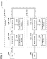
- FIG. 1 is a block diagram schematically illustrating a communication system 100 including relay devices 110A to 110D according to the first embodiment.
- the communication system 100 includes a network 101A and a network 101B.
- the network 101A includes the relay devices 110A and 110B and communication devices 103A and 103B.
- the relay device 110A is connected to a GM 104A, and a clock-time synchronization frame for synchronizing the clock time is sent from the GM 104A to the relay device 110A.
- the network 101A is also referred to as a first network.
- Any one of the relay devices 110A and 110B is also referred to as a first relay device.
- the GM 104A is also referred to as a first clock-time distribution server, and the clock-time synchronization frame sent from the GM 104A is also referred to as a first clock-time synchronization frame.
- the network 101B includes the relay devices 110C and 110D and communication devices 103C and 103D.
- the relay device 110C is connected to a GM 104B, and a clock-time synchronization frame for synchronizing the clock time is sent from the GM 104B to the relay device 110C.
- the network 101B is also referred to as a second network. Any one of the relay devices 110C and 110D is also referred to as a second relay device.
- the GM 104B is also referred to as a second clock-time distribution server, and the clock-time synchronization frame sent from the GM 104B is also referred to as a second clock-time synchronization frame.
- devices illustrated at the same locations on the network 101A and the network 101B such as the communication device 103A and the communication device 103C, are disposed in the same area and are capable of providing the same service.
- the user can receive the service via both networks 101A and 101B.
- the network 101A and the network 101B constitute different segments.
- the network 101A and the network 101B constituting different segments are usually not connected.
- the relay devices 110B and 110D having a filter function for transmitting only clock-time synchronization frames are provided to connect the networks 101A and 101B without mixing of the communication frames.
- the two GMs 104A and 104B are present in the communication system 100; and the GM having high priority (for example, the GM 104A in FIG. 1 ) is selected by using the BMCA or the like, and relay devices 110A to 110D and the communication devices 103A to 103D connected to both networks 101A and 101B are synchronized with the clock time of the selected GM.
- the communication devices 103A and 103B may be any devices capable of communication via the network 101A.
- each of the GMs 104A and 104B should include one clock-time-information distribution port for sending clock-time synchronization frames indicating the clock time to be synchronized.
- the clock-time-information distribution port is a physical port that sends clock-time synchronization frames to a network. Note that the clock time indicated by a clock-time synchronization frame is the reference clock time.
- relay devices 110A to 110D have the same configuration, hereinafter, any one of the relay devices 110A to 110D will be referred to as a relay device 110 when there is no need to distinguish between them.
- FIG. 2 is a block diagram schematically illustrating the configuration of a relay device 110.
- the relay device 110 includes a plurality of physical ports 111-1 to 111-N (where N is an integer equal to or greater than two), a clock-time-information-relay-port setting unit 112, a layer-2 protocol processing unit 113, a clock-time synchronization processing unit 114, and a time counting unit 115.
- Each of the physical ports 111-1 to 111-N serves as a communication interface for connecting to a network.
- Each of the physical ports 111-1 to 111-N sends and receives frames.
- At least one of the physical ports 111-1 to 111-N is selected by the clock-time-information-relay-port setting unit 112 as a clock-time-information relay port to which a filter function for transmitting only clock-time synchronization frames is applied.
- the clock-time-information relay port is connected to a relay device 110 of a different segment.
- the physical ports 111-1 to 111-N provided in the first relay device are also referred to as first ports
- the physical ports 111-1 to 111-N provided in the second relay device are also referred to as second ports.
- the clock-time-information-relay-port setting unit 112 notifies the layer-2 protocol processing unit 113 of a clock-time-information relay port number or physical-port identification information for identifying the clock-time-information relay port to which the filter function for transmitting only clock-time synchronization frames is applied.
- the clock-time-information relay port is used to connect the two network systems described above and is a physical port to which the filter function for transmitting only clock-time synchronization frames is applied.
- the clock-time-information relay port may be predetermined or may be selected by a user.
- the clock-time-information-relay-port setting unit 112 receives a designation of a clock-time-information relay port number from a user terminal connected to any of the physical ports 111-1 to 111-N and selects the physical port identified by the designated clock-time-information relay port number to be the clock-time-information relay port.
- the clock-time-information relay port number may be input through such an input unit.
- the clock-time-information-relay-port setting unit 112 does not report the clock-time-information relay port number to the layer-2 protocol processing unit 113 or reports a predetermined number indicating that the clock-time-information relay port is not to be used to the layer-2 protocol processing unit 113.
- the relay device 110B and the relay device 110D use clock-time-information relay ports, but the relay device 110A and the relay device 110C do not use clock-time-information relay ports. Therefore, in the first embodiment, the relay devices 110A and 110C may be relay devices having a clock-time synchronization function.
- the layer-2 protocol processing unit 113 is a transfer processing unit that transfers a frame received by one physical port included in the physical ports 111-1 to 111-N from at least one of the physical ports 111-1 to 111-N.
- the layer-2 protocol processing unit 113 has a filtering function for blocking frames other than clock-time synchronization frames in the transfer involving the clock-time-information relay ports.
- the layer-2 protocol processing unit 113 applies a filtering function to the frames received by the clock-time-information relay port.
- the layer-2 protocol processing unit 113 deletes the frame.
- the layer-2 protocol processing unit 113 does not transfer the frame from any of the physical ports 111-1 to 111-N.
- the frame received by the clock-time-information relay port is also referred to as a first frame.
- the layer-2 protocol processing unit 113 checks whether or not the physical port that received the frame matches the physical port indicated by the clock-time-information relay port number reported by the clock-time-information-relay-port setting unit 112.
- the layer-2 protocol processing unit 113 When any of the physical ports 111-1 to 111-N receives a frame, the layer-2 protocol processing unit 113 also checks whether or not the frame is a clock-time synchronization frame.
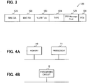
- FIG. 3 is a schematic diagram illustrating the format of a clock-time synchronization frame defined by IEEE1588 PTP or IEEE802.1AS.
- a clock-time synchronization frame 120 includes a media access control destination address (MAC DA) area 121, a media access control source address (MAC SA) area 122, a virtual local area network (VLAN) field area 123, a TYPE area 124, a PTP message field area 125, and a frame check sequence (FCS) area 126.
- MAC DA media access control destination address
- MAC SA media access control source address
- VLAN virtual local area network
- TYPE TYPE
- PTP message field area 125 a PTP message field area 125
- FCS frame check sequence
- the layer-2 protocol processing unit 113 can determine whether or not the received frame is a clock-time synchronization frame by checking the MAC DA area 121 and the TYPE area 124 of the received frame.
- the clock-time synchronization frame received via the clock-time-information distribution path between the two networks is terminated at the relay device 110 and is discarded without being transferred.
- the layer-2 protocol processing unit 113 feeds the clock-time synchronization frame to the clock-time synchronization processing unit 114.
- the layer-2 protocol processing unit 113 discards the frame.
- the layer-2 protocol processing unit 113 refers to the values in the MAC DA area and the VLAN area of the frame and transfers the frame to any of the physical ports other than the physical port that received the frame and the clock-time-information relay port in the same segment as the physical port that received the frame.
- the frames processed by the clock-time-information relay port through the above-described processing can be limited to clock-time synchronization frames.
- the frame received by a physical port other than the clock-time-information relay port is also referred to as a second frame.
- the filtering function executed by the layer-2 protocol processing unit 113 of the first relay device is also referred to as a first filtering function
- the filtering function executed by the layer-2 protocol processing unit 113 of the second relay device is also referred to as a second filtering function.
- the clock-time synchronization processing unit 114 processes the clock-time synchronization frame received from the layer-2 protocol processing unit 113 on the basis of the specification of IEEE1588 PTP or IEEE802.1AS. For example, the clock-time synchronization processing unit 114 controls the time counting unit 115 to synchronize the clock time counted by the time counting unit 115 with the clock time indicated by the clock-time synchronization frame received from the layer-2 protocol processing unit 113.
- the clock-time synchronization processing unit 114 When the clock-time synchronization processing unit 114 receives the clock-time synchronization frame from the layer-2 protocol processing unit 113, the clock-time synchronization processing unit 114 generates a clock-time synchronization frame on the basis of the specification of IEEE1588 PTP or IEEE802.1AS. The clock-time synchronization processing unit 114 then determines the physical port to which the clock-time synchronization frame generated on the basis of the specification of the IEEE1588 PTP or IEEE802.1AS is to be output.
- the clock-time synchronization processing unit 114 sends the generated clock-time synchronization frame from all physical ports except the physical port that received the clock-time synchronization frame.
- the clock-time synchronization processing unit 114 sends the generated clock-time synchronization frame from a physical port in the same segment as the physical port that received the clock-time synchronization frame (excluding the port that received the clock-time synchronization frame) and the clock-time-information relay port.
- the time counting unit 115 counts clock time.
- the time counting unit 115 counts clock time on the basis of a signal from an oscillator or a vibrator transducer, which is a clock source not illustrated.
- the plurality of physical ports 111-1 to 111-N of the first relay device is also referred to as a plurality of first physical ports;
- the clock-time-information-relay-port setting unit 112 of the first relay device is also referred to as a first clock-time-information-relay-port setting unit;
- the layer-2 protocol processing unit 113 of the first relay device is also referred to as a first transfer processing unit;
- the clock-time synchronization processing unit 114 of the first relay device is also referred to as a first clock-time synchronization processing unit;
- the time counting unit 115 of the first relay device is also referred to as a first time counting unit.
- the clock-time-information relay port of the first relay device is also referred to as a first clock-time-information relay port.
- the plurality of physical ports 111-1 to 111-N of the second relay device is also referred to as a plurality of second physical ports;
- the clock-time-information-relay-port setting unit 112 of the second relay device is also referred to as a second clock-time-information-relay-port setting unit;
- the layer-2 protocol processing unit 113 of the second relay device is also referred to as a second transfer processing unit;
- the clock-time synchronization processing unit 114 of the second relay device is also referred to as a second clock-time synchronization processing unit;
- the time counting unit 115 of the second relay device is also referred to as a second time counting unit.
- the clock-time-information relay port of the second relay device is also referred to as a second clock-time-information relay port.
- a portion or the entirety of the clock-time-information-relay-port setting unit 112, the layer-2 protocol processing unit 113, the clock-time synchronization processing unit 114, and the time counting unit 115 described above can be implemented by, for example, a memory 10 and a processor 11, such as a central processing unit (CPU), that executes the programs stored in the memory 10, as illustrated in FIG. 4A .
- a processor 11 such as a central processing unit (CPU)
- Such programs may be provided via a network or may be recorded and provided on a recording medium. That is, such programs may be provided as, for example, program products.
- a portion or the entirety of the clock-time-information-relay-port setting unit 112, the layer-2 protocol processing unit 113, the clock-time synchronization processing unit 114, and the time counting unit 115 can be implemented by, for example, a processing circuit 12, such as a single circuit, a composite circuit, a programmed processor, a parallel programmed processor, an application-specific integrated circuit (ASIC), or a field-programmable gate array (FPGA), as illustrated in FIG. 4B .
- a processing circuit 12 such as a single circuit, a composite circuit, a programmed processor, a parallel programmed processor, an application-specific integrated circuit (ASIC), or a field-programmable gate array (FPGA), as illustrated in FIG. 4B .
- the clock-time-information-relay-port setting unit 112 the layer-2 protocol processing unit 113, the clock-time synchronization processing unit 114, and the time counting unit 115 can be implemented by processing circuity.
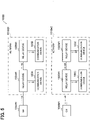
- FIG. 5 is a block diagram schematically illustrating the configuration of a communication system 100#1 according to a first comparative example for comparison with the communication system 100 according to the first embodiment.
- the communication system 100#1 includes a network 101A#1 and a network 101B#1.
- the network 101A#1 includes relay devices 102A#1 and 102B#1 and communication devices 103A and 103B.
- the relay device 102A#1 is connected to a GM 104A#1, and a clock-time synchronization frame for synchronizing clock time is sent from the GM 104A#1 to the relay device 102A#1.
- the network 101B#1 includes relay devices 102C#1 and 102D#1 and communication devices 103C and 103D.
- the relay device 102C#1 is connected to a GM 104B#1, and a clock-time synchronization frame for synchronizing clock time is sent from the GM 104B#1 to the relay device 102C#1.
- the communication system 100#1 according to the first comparative example is a simple full-duplex network configuration example consisting of three types of devices: GMs 104A#1 and 104B#1, relay devices 102A#1 to 102D#1, and communication devices 103A to 130D.
- each of the relay devices 102A#1 to 102D#1 can be implemented by, for example, a relay device having a clock-time synchronization function.
- the devices on the network 101A#1 are synchronized with the clock time delivered by the GM 104A#1, and the devices on the network 101B#1 are synchronized with the clock time delivered by the GM 104B#1.
- the network including the failed GM cannot provide normal service until the GM is replaced even if the devices other than the GM are operating normally because there is no means for synchronizing the clock time between the devices on the network.
- the service must be stopped in case of double failure, which is a state in which failure or malfunction occurs in an operating network including no failed GMs, before replacement of the failed GM.
- FIG. 6 is a block diagram schematically illustrating the configuration of a communication system 100#2 according to a second comparative example for comparison with the communication system 100 according to the first embodiment.
- the communication system 100#2 includes a network 101A#2 and a network 101B#2.
- the network 101A#2 includes relay devices 102A#2 and 102B#2 and communication devices 103A and 103B.
- the relay device 102A#2 is connected to a GM 104A#2 and a GM 104B#2, and clock-time synchronization frames for synchronizing the clock time are sent from the GM 104A#2 and the GM104B#2 to the relay device 102A#2.
- the network 101B#2 includes relay devices 102C#2 and 102D#2 and communication devices 103C and 103D.
- the relay device 102C#2 is connected to the GM 104B#2 and the GM 104A#2, and clock-time synchronization frames for synchronizing the clock time are sent from the GM 104B#2 and the GM104A#2 to the relay device 102C#2.
- the GMs 104A#2 and 104B#2 each include two clock-time information distribution ports for sending clock-time synchronization frames.
- each of the relay devices 110A#2 to 102D#2 can be implemented by, for example, a relay device having a clock-time synchronization function.
- clock-time information can be distributed to both the networks 101A#2 and 101B#2.
- each of the communication devices 103A to 103D selects the GM having high priority (for example, 104A#2) by using the BMCA or the like and synchronizes the clock time with the clock time of the selected GM.
- the GM 104B#2 operating normally can distribute clock-time information to both the networks 101A#2 and 101B#2. Therefore, even in such a case, the service can be continuously provided on both networks 101A#2 and 101B#2.
- the service can be continuously provided even in case of double failure, which is a state in which failure or malfunction occurs in an operating network 101A#2, 101B#2, before replacement of the failed GM 104A#2, except for when (a) both GMs fail or (b) communication failure (for example, failure of a relay device or failure of the communication path between relay devices) occurs in both networks. Therefore, it can be said that the configuration illustrated in FIG. 6 has higher fault tolerance than that of the configuration illustrated in FIG. 5 .
- the price of a GM increases in proportion to an increase in the number of ports capable of distributing clock-time information.
- FIG. 8 is a block diagram for describing a clock-time information distribution path when one GM 104A fails in the communication system 100 according to the first embodiment.
- the service can be continuously provided in both networks 101A and 101B even if one GM 104A fails because the clock-time information distributed by the GM 104B operating normally is distributed to both networks 101A and 101B via the wiring between the relay devices 110B and 110D.
- the service can be continuously provided even in case of double failure, which is a state in which failure or malfunction occurs in the operating network 101A, 101B, before replacement of the failed GM 104A.
- the communication system 100 can achieve availability equivalent to that of the communication system 100#2 illustrated in FIG. 6 by using the relay devices 110B and 110D having a filter function for transmitting only clock-time synchronization frames by using the GMs 104A and 104B each having one clock-time information distribution port, as in the communication system 100#1 illustrated in FIG. 5 .
- both networks 101A and 101B are connected by one wire
- the first embodiment is not limited to such an example.
- both networks 101A and 101B can be connected by two wires by also connecting the relay devices 110A and 110C.
- the communication system 100 proposes a clock-time synchronization method in which the GMs 104A and 104B have a redundant configuration and at least one GM can be expected to operate normally.
- the second embodiment proposes a clock-time synchronization method for a case in which the GMs 104A and 104B distributing clock-time information are absent due to failure or the like, and the operation must be continued during the period until the GMs 104A and 104B are replaced.
- a communication system 200 includes a network 201A and a network 201B.
- the network 201A includes relay devices 210A and 210B and communication devices 103A and 103B.
- the relay device 210A is connected to a GM 104A, and clock-time synchronization frames for synchronizing the clock time are sent from the GM 104A to the relay device 210A.
- the network 201B includes relay devices 210C and 210D and communication devices 103C and 103D.
- the relay device 210C is connected to a GM 104B, and clock-time synchronization frames for synchronizing the clock time are sent from the GM 104B to the relay device 210C.
- the network 201A and the network 201B constitute different segments also in second embodiment.
- the communication devices 103A to 103D and the GMs 104A and 104B of the communication system 200 according to the second embodiment are the same as the communication devices 103A to 103D and the GMs 104A and 104B, respectively, in the communication system 100 according to the first embodiment.
- relay devices 210A to 210D have the same configuration, hereinafter, any one of the relay devices 210A to 210D will be referred to as a relay device 210 when there is no need to distinguish between them.
- the relay device 210 includes a plurality of physical ports 111-1 to 111-N, a clock-time-information-relay-port setting unit 112, a layer-2 protocol processing unit 113, and a clock-time synchronization processing unit 214.
- the plurality of physical ports 111-1 to 111-N, the clock-time-information-relay-port setting unit 112, and the layer-2 protocol processing unit 113 in the relay device 210 according to the second embodiment are the same as the plurality of physical ports 111-1 to 111-N, the clock-time-information relay port setting unit 112, and the layer-2 protocol processing unit 113, respectively, in the relay device110 according to the first embodiment.
- the clock-time synchronization processing unit 214 generates clock-time synchronization frames indicating the clock time counted by the time counting unit 115 when a GM connected to any of the physical ports 111-1 to 111-N becomes absent.
- the clock-time synchronization frames generated by the clock-time synchronization processing unit 214 are also referred to as alternative clock-time synchronization frames.
- the clock-time synchronization processing unit 214 performs the same processing as the clock-time synchronization processing unit 114 according to the first embodiment and generates a clock-time synchronization frame based on the specification of the IEEE1588 PTP or IEEE802.1AS by using the clock time counted by the time counting unit 115 in place of the GMs 104A and 104B when the GMs 104A and 104B become absent and when the clock-time synchronization processing unit 214 is located in the nearest neighbor of the last operating GM.
- the clock-time synchronization processing unit 214 checks the number of relay stages between the relay device 210 and the last operating GM by using the index value "stepsRemoved" stored in the Priority Vector area in the Announce message included in the clock-time synchronization packet defined by the BMCA.
- the GMs 104A and 104B send clock-time synchronization control frames known as Announce frames in a given cycle; thereby, the clock-time synchronization processing unit 214 can determine that the GMs 104A and 104B are absent when the physical ports 111-1 to 111-N connected to the GM 104A or the GM 104B do not receive an Announce frame in a predetermined period. In other words, the clock-time synchronization processing unit 214 can determine that the GMs 104A and 104B are absent when a predetermined frame is not received in a predetermined period.
- the clock-time synchronization processing unit 114 determines the physical port to which the clock-time synchronization frame generated on the basis of the specification of the IEEE1588 PTP or IEEE802.1AS is to be output.
- clock-time synchronization frames are sent from all physical ports via the layer-2 protocol processing unit 113.
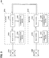
- the service when one GM 104A fails and the service is continuously provided on both networks 201A and 201B by clock-time information distributed by the GM 104B operating normally, for example, as illustrated in FIG. 8 , the service can be continuously provided on both networks 201A and 201B even if the GM 104B fails, as illustrated in FIG. 9 , by distributing clock-time information from the relay device 210C adjacent to the GM 104B, which was distributing clock-time information until most recently.
- the oscillator or vibrator serving as the clock source of the relay device 210 has accuracy lower than the clock-time accuracy of the GMs 104A and 104B, and there is variation in the clock deviation of each device, it is desirable to select the relay device 210 located in the nearest neighbor of the last operating GM as the relay device 210 for synchronizing the clock time.
- first alternative clock-time synchronization frames are also referred to as first alternative clock-time synchronization frames
- second alternative clock-time synchronization frames are also referred to as second alternative clock-time synchronization frames
- 100, 200 communication system 101, 201 network; 103 communication device; 104 GM; 110, 210 relay device; 111-1 to 111-N physical port; 112 clock-time-information-relay-port setting unit; 113 layer-2 protocol processing unit; 114, 214 clock-time synchronization processing unit; 115 time counting unit.
Landscapes
- Engineering & Computer Science (AREA)
- Computer Networks & Wireless Communication (AREA)
- Signal Processing (AREA)
- Small-Scale Networks (AREA)
- Synchronisation In Digital Transmission Systems (AREA)
- Data Exchanges In Wide-Area Networks (AREA)
Abstract
Description
- The present invention relates to a relay device and a communication system.
- According to IEEE1588 precision time protocol (PTP) or IEEE802.1AS standardized by the Institute of Electrical and Electronics Engineers (IEEE), a grand master (GM), which is a clock-time distribution server including a reference clock of a network, counts reference clock time and distributes clock-time information indicating the clock time in a clock-time synchronization frame, and a device that receives the clock-time information from the GM corrects the clock time. This enables synchronization of the clock time in the network.
- An industrial network or a network forming a social infrastructure is composed of a full-duplex system for a network to improve the fault tolerance and has a configuration in which multiple GMs are arranged on the network to achieve highly accurate clock-time synchronization. In a network having a redundant configuration of GMs, one GM is selected to distribute clock time by using the best master clock algorithm (BMCA) or the like to centralize the clock time to be synchronized, and a clock-time distribution tree is generated with the selected GM serving as a starting point.
- When a GM in operation enters a state of malfunction or communication failure, another GM for distributing clock-time information is selected from the GMs operating normally to maintain the clock-time synchronization accuracy of the devices belonging to the network (for example, refer to Patent Literature 1).
- Patent Literature 1:
Japanese Patent No. 6045950 - Since a GM distributes clock-time information from a clock-time information distribution port, it is necessary to provide multiple clock-time information distribution ports on the GM when redundancy is established in accordance with the conventional technique.
- In general, a GM adopts an expensive, high-precision reference clock using an atomic clock, a global positioning system (GPS), or the like to distribute high-precision clock-time information; thus, a GM is more expensive than a relay device, such as a layer-2 switch (L2SW). The price of a GM increases in proportion to an increase in the number of clock-time information distribution ports.
- Therefore, in the conventional technique, a plurality of relatively expensive GMs having many clock-time information distribution ports are arranged on a network to enhance fault tolerance, but the price of GMs causes deterioration in cost.
- Accordingly, it is an object of one or more aspects of the present invention to enable clock-time synchronization with high reliability at a low cost.
- A relay device according to an aspect of the present invention includes a plurality of ports configured to receive frames; and a transfer processing unit configured to transfer a frame received at one of the ports to at least one of the ports, wherein the transfer processing unit has a filtering function for blocking frames other than a clock-time synchronization frame during transfer involving the port selected from the plurality of ports, the clock-time synchronization frame being used for synchronizing clock time.
- A communication system according to an aspect of the present invention includes a first network including a first relay device; and a second network including a second relay device and constituting a segment different from the segment of the first network, wherein, the first relay device further includes: a plurality of first ports configured to receive frames; and a first transfer processing unit configured to transfer a frame received by one of the first ports from at least one of the first ports, a first clock-time-information relay port included in the plurality of first ports is connected to the second relay device, the first transfer processing unit has a first filtering function for blocking frames other than a clock-time synchronization frame during transfer involving the first clock-time-information relay port, the clock-time synchronization frame being used for synchronizing clock time, the second relay device further includes: a plurality of second ports configured to receive frames; and a second transfer processing unit configured to transfer a frame received by one of the second ports to at least one of the second ports, a second clock-time-information relay port included in the plurality of second ports is connected to the first relay device, and the second transfer processing unit has a second filtering function for blocking frames other than the clock-time synchronization frame during transfer involving the second clock-time information relay port.
- One or more aspects of the present invention enable clock-time synchronization with high reliability at a low cost.
-
-
FIG. 1 is a block diagram schematically illustrating a communication system including relay devices according to first and second embodiments. -
FIG. 2 is a block diagram schematically illustrating the configuration of a relay device according to the first and second embodiments. -
FIG. 3 is a schematic diagram illustrating a format of a clock-time synchronization frame. -
FIGS. 4A and 4B are block diagrams illustrating hardware configuration examples. -
FIG. 5 is a block diagram schematically illustrating the configuration of a communication system according to a first comparative example. -
FIG. 6 is a block diagram schematically illustrating the configuration of a communication system according to a second comparative example. -
FIG. 7 is a block diagram for describing a clock-time-information distribution path when one GM fails in the second comparative example. -
FIG. 8 is a block diagram for describing a clock-time-information distribution path when one GM fails in the first and second embodiments. -
FIG. 9 is a block diagram for describing a clock-time-information distribution path when two GMs fail in the second embodiment. -
FIG. 1 is a block diagram schematically illustrating acommunication system 100 includingrelay devices 110A to 110D according to the first embodiment. - The
communication system 100 includes anetwork 101A and anetwork 101B. - The
network 101A includes therelay devices communication devices - The
relay device 110A is connected to a GM 104A, and a clock-time synchronization frame for synchronizing the clock time is sent from the GM 104A to therelay device 110A. - Here, the
network 101A is also referred to as a first network. Any one of therelay devices - The
network 101B includes therelay devices communication devices - The
relay device 110C is connected to a GM 104B, and a clock-time synchronization frame for synchronizing the clock time is sent from the GM 104B to therelay device 110C. - Here, the
network 101B is also referred to as a second network. Any one of therelay devices - For example, devices illustrated at the same locations on the
network 101A and thenetwork 101B, such as thecommunication device 103A and thecommunication device 103C, are disposed in the same area and are capable of providing the same service. When both thenetwork 101A and thenetwork 101B are operating normally, the user can receive the service via bothnetworks - The
network 101A and thenetwork 101B constitute different segments. - To avoid mixing of communication frames, the
network 101A and thenetwork 101B constituting different segments are usually not connected. However, in thecommunication system 100 according to the first embodiment, therelay devices networks - Note that, when both the GM 104A and the GM 104B are operating normally in the configuration illustrated in
FIG. 1 , the two GMs 104A and 104B are present in thecommunication system 100; and the GM having high priority (for example, the GM 104A inFIG. 1 ) is selected by using the BMCA or the like, andrelay devices 110A to 110D and thecommunication devices 103A to 103D connected to bothnetworks - The
communication devices network 101A. - Furthermore, each of the GMs 104A and 104B should include one clock-time-information distribution port for sending clock-time synchronization frames indicating the clock time to be synchronized. The clock-time-information distribution port is a physical port that sends clock-time synchronization frames to a network. Note that the clock time indicated by a clock-time synchronization frame is the reference clock time.
- Since the
relay devices 110A to 110D have the same configuration, hereinafter, any one of therelay devices 110A to 110D will be referred to as a relay device 110 when there is no need to distinguish between them. -
FIG. 2 is a block diagram schematically illustrating the configuration of a relay device 110. - The relay device 110 includes a plurality of physical ports 111-1 to 111-N (where N is an integer equal to or greater than two), a clock-time-information-relay-
port setting unit 112, a layer-2protocol processing unit 113, a clock-time synchronization processing unit 114, and atime counting unit 115. - Each of the physical ports 111-1 to 111-N serves as a communication interface for connecting to a network. Each of the physical ports 111-1 to 111-N sends and receives frames.
- At least one of the physical ports 111-1 to 111-N is selected by the clock-time-information-relay-
port setting unit 112 as a clock-time-information relay port to which a filter function for transmitting only clock-time synchronization frames is applied. The clock-time-information relay port is connected to a relay device 110 of a different segment. - Note that the physical ports 111-1 to 111-N provided in the first relay device are also referred to as first ports, and the physical ports 111-1 to 111-N provided in the second relay device are also referred to as second ports.
- The clock-time-information-relay-
port setting unit 112 notifies the layer-2protocol processing unit 113 of a clock-time-information relay port number or physical-port identification information for identifying the clock-time-information relay port to which the filter function for transmitting only clock-time synchronization frames is applied. The clock-time-information relay port is used to connect the two network systems described above and is a physical port to which the filter function for transmitting only clock-time synchronization frames is applied. - The clock-time-information relay port may be predetermined or may be selected by a user.
- For example, the clock-time-information-relay-
port setting unit 112 receives a designation of a clock-time-information relay port number from a user terminal connected to any of the physical ports 111-1 to 111-N and selects the physical port identified by the designated clock-time-information relay port number to be the clock-time-information relay port. - Note that, although not illustrated, in the case where the relay device 110 is provided with an input unit for receiving input of an instruction from a user, the clock-time-information relay port number may be input through such an input unit.
- Note that when a clock-time-information relay port is not used, the clock-time-information-relay-
port setting unit 112 does not report the clock-time-information relay port number to the layer-2protocol processing unit 113 or reports a predetermined number indicating that the clock-time-information relay port is not to be used to the layer-2protocol processing unit 113. In thecommunication system 100 illustrated inFIG. 1 , therelay device 110B and therelay device 110D use clock-time-information relay ports, but therelay device 110A and therelay device 110C do not use clock-time-information relay ports. Therefore, in the first embodiment, therelay devices - The layer-2
protocol processing unit 113 is a transfer processing unit that transfers a frame received by one physical port included in the physical ports 111-1 to 111-N from at least one of the physical ports 111-1 to 111-N. - Here, the layer-2
protocol processing unit 113 has a filtering function for blocking frames other than clock-time synchronization frames in the transfer involving the clock-time-information relay ports. - For example, the layer-2
protocol processing unit 113 applies a filtering function to the frames received by the clock-time-information relay port. When the frame received by the clock-time-information relay port is not a clock-time synchronization frame, the layer-2protocol processing unit 113 deletes the frame. Alternatively, when the frame received by the clock-time-information relay port is not a clock-time synchronization frame, the layer-2protocol processing unit 113 does not transfer the frame from any of the physical ports 111-1 to 111-N. Here, the frame received by the clock-time-information relay port is also referred to as a first frame. - Specifically, when any of the physical ports 111-1 to 111-N receives a frame, the layer-2
protocol processing unit 113 checks whether or not the physical port that received the frame matches the physical port indicated by the clock-time-information relay port number reported by the clock-time-information-relay-port setting unit 112. - When any of the physical ports 111-1 to 111-N receives a frame, the layer-2
protocol processing unit 113 also checks whether or not the frame is a clock-time synchronization frame. -
FIG. 3 is a schematic diagram illustrating the format of a clock-time synchronization frame defined by IEEE1588 PTP or IEEE802.1AS. - A clock-
time synchronization frame 120 includes a media access control destination address (MAC DA)area 121, a media access control source address (MAC SA)area 122, a virtual local area network (VLAN)field area 123, aTYPE area 124, a PTPmessage field area 125, and a frame check sequence (FCS)area 126. - In the clock-time synchronization frame of the first embodiment, "01-80-C2-00-00-0E" is stored in the
MAC DA area 121 for storing a destination MAC address, and "0x88 F7" indicating PTP is stored in theTYPE area 124 for indicating an Ethernet (registered trademark) protocol. - Therefore, the layer-2
protocol processing unit 113 can determine whether or not the received frame is a clock-time synchronization frame by checking theMAC DA area 121 and theTYPE area 124 of the received frame. - Note that since the destination MAC address "01-80-C2-00-00-0E" is a link-by-link address indicating that transfer is not allowed, the clock-time synchronization frame received via the clock-time-information distribution path between the two networks is terminated at the relay device 110 and is discarded without being transferred.
- If the checking results in the received frame being a clock-time synchronization frame, the layer-2
protocol processing unit 113 feeds the clock-time synchronization frame to the clock-time synchronization processing unit 114. - In contrast, if the received frame is not a clock-time synchronization frame, and the physical port that received the frame is a clock-time-information relay port, the layer-2
protocol processing unit 113 discards the frame. - If the received frame is not a clock-time synchronization frame, and the physical port that received the frame is not a clock-time information relay port, the layer-2
protocol processing unit 113 refers to the values in the MAC DA area and the VLAN area of the frame and transfers the frame to any of the physical ports other than the physical port that received the frame and the clock-time-information relay port in the same segment as the physical port that received the frame. - In the relay device 110, the frames processed by the clock-time-information relay port through the above-described processing can be limited to clock-time synchronization frames. Here, the frame received by a physical port other than the clock-time-information relay port is also referred to as a second frame.
- Note that the filtering function executed by the layer-2
protocol processing unit 113 of the first relay device is also referred to as a first filtering function, and the filtering function executed by the layer-2protocol processing unit 113 of the second relay device is also referred to as a second filtering function. - The clock-time synchronization processing unit 114 processes the clock-time synchronization frame received from the layer-2
protocol processing unit 113 on the basis of the specification of IEEE1588 PTP or IEEE802.1AS. For example, the clock-time synchronization processing unit 114 controls thetime counting unit 115 to synchronize the clock time counted by thetime counting unit 115 with the clock time indicated by the clock-time synchronization frame received from the layer-2protocol processing unit 113. - When the clock-time synchronization processing unit 114 receives the clock-time synchronization frame from the layer-2
protocol processing unit 113, the clock-time synchronization processing unit 114 generates a clock-time synchronization frame on the basis of the specification of IEEE1588 PTP or IEEE802.1AS. The clock-time synchronization processing unit 114 then determines the physical port to which the clock-time synchronization frame generated on the basis of the specification of the IEEE1588 PTP or IEEE802.1AS is to be output. - For example, when the clock-time-information relay port receives the clock-time synchronization frame, the clock-time synchronization processing unit 114 sends the generated clock-time synchronization frame from all physical ports except the physical port that received the clock-time synchronization frame.
- In contrast, when a physical port other than the clock-time-information relay port receives the clock-time synchronization frame, the clock-time synchronization processing unit 114 sends the generated clock-time synchronization frame from a physical port in the same segment as the physical port that received the clock-time synchronization frame (excluding the port that received the clock-time synchronization frame) and the clock-time-information relay port.
- The
time counting unit 115 counts clock time. For example, thetime counting unit 115 counts clock time on the basis of a signal from an oscillator or a vibrator transducer, which is a clock source not illustrated. - Note that the plurality of physical ports 111-1 to 111-N of the first relay device is also referred to as a plurality of first physical ports; the clock-time-information-relay-
port setting unit 112 of the first relay device is also referred to as a first clock-time-information-relay-port setting unit; the layer-2protocol processing unit 113 of the first relay device is also referred to as a first transfer processing unit; the clock-time synchronization processing unit 114 of the first relay device is also referred to as a first clock-time synchronization processing unit; and thetime counting unit 115 of the first relay device is also referred to as a first time counting unit. The clock-time-information relay port of the first relay device is also referred to as a first clock-time-information relay port. - Moreover, the plurality of physical ports 111-1 to 111-N of the second relay device is also referred to as a plurality of second physical ports; the clock-time-information-relay-
port setting unit 112 of the second relay device is also referred to as a second clock-time-information-relay-port setting unit; the layer-2protocol processing unit 113 of the second relay device is also referred to as a second transfer processing unit; the clock-time synchronization processing unit 114 of the second relay device is also referred to as a second clock-time synchronization processing unit; and thetime counting unit 115 of the second relay device is also referred to as a second time counting unit. The clock-time-information relay port of the second relay device is also referred to as a second clock-time-information relay port. - For example, a portion or the entirety of the clock-time-information-relay-
port setting unit 112, the layer-2protocol processing unit 113, the clock-time synchronization processing unit 114, and thetime counting unit 115 described above can be implemented by, for example, amemory 10 and aprocessor 11, such as a central processing unit (CPU), that executes the programs stored in thememory 10, as illustrated inFIG. 4A . Such programs may be provided via a network or may be recorded and provided on a recording medium. That is, such programs may be provided as, for example, program products. - A portion or the entirety of the clock-time-information-relay-
port setting unit 112, the layer-2protocol processing unit 113, the clock-time synchronization processing unit 114, and thetime counting unit 115 can be implemented by, for example, aprocessing circuit 12, such as a single circuit, a composite circuit, a programmed processor, a parallel programmed processor, an application-specific integrated circuit (ASIC), or a field-programmable gate array (FPGA), as illustrated inFIG. 4B . - That is, the clock-time-information-relay-
port setting unit 112, the layer-2protocol processing unit 113, the clock-time synchronization processing unit 114, and thetime counting unit 115 can be implemented by processing circuity. - The advantages of the
communication system 100 according to the first embodiment will now be described. -
FIG. 5 is a block diagram schematically illustrating the configuration of acommunication system 100#1 according to a first comparative example for comparison with thecommunication system 100 according to the first embodiment. - The
communication system 100#1 includes anetwork 101A#network 101B# - The
network 101A#relay 1 anddevices 102A#102B# 1 andcommunication devices - The
relay 1 is connected to adevice 102A#GM 104A#GM 104A#relay 1.device 102A# - The
network 101B#relay 1 anddevices 102C#102D# 1 andcommunication devices - The
relay 1 is connected to adevice 102C#GM 104B#GM 104B#relay 1.device 102C# - The
communication system 100#1 according to the first comparative example is a simple full-duplex network configuration example consisting of three types of devices:GMs 104A#104B# 1,relay 1 to 102D#1, anddevices 102A#communication devices 103A to 130D. - Here, each of the
relay 1 to 102D#1 can be implemented by, for example, a relay device having a clock-time synchronization function.devices 102A# - In the configuration illustrated in
FIG. 5 , the devices on thenetwork 101A#GM 104A#network 101B#GM 104B#FIG. 5 , even if one of theGMs 104A#104B# 1 fails, communication with clock-time synchronization is possible in one network. However, the network including the failed GM cannot provide normal service until the GM is replaced even if the devices other than the GM are operating normally because there is no means for synchronizing the clock time between the devices on the network. Moreover, the service must be stopped in case of double failure, which is a state in which failure or malfunction occurs in an operating network including no failed GMs, before replacement of the failed GM. -
FIG. 6 is a block diagram schematically illustrating the configuration of acommunication system 100#2 according to a second comparative example for comparison with thecommunication system 100 according to the first embodiment. - The
communication system 100#2 includes anetwork 101A#network 101B# - The
network 101A#relay 2 anddevices 102A#102B# 2 andcommunication devices - The
relay 2 is connected to adevice 102A#GM 104A#GM 104B#GM 104A#GM104B# 2 to therelay 2.device 102A# - The
network 101B#relay 2 anddevices 102C#102D# 2 andcommunication devices - The
relay 2 is connected to thedevice 102C#GM 104B#GM 104A#GM 104B#GM104A# 2 to therelay 2.device 102C# - In the configuration illustrated in
FIG. 6 , theGMs 104A#104B# 2 each include two clock-time information distribution ports for sending clock-time synchronization frames. - Here, each of the
relay 2 to 102D#2 can be implemented by, for example, a relay device having a clock-time synchronization function.devices 110A# - In the configuration illustrated in
FIG. 6 , since each of theGMs 104A#104B# 2 has two clock-time information distribution ports, clock-time information can be distributed to both thenetworks 101A#101B# 2. - In the configuration illustrated in
FIG. 6 , two GMs are present in each of thenetworks 101A#101B# 2. Therefore, each of thecommunication devices 103A to 103D selects the GM having high priority (for example, 104A#2) by using the BMCA or the like and synchronizes the clock time with the clock time of the selected GM. - In the configuration illustrated in
FIG. 6 , even if theGM 104A#FIG. 7 , theGM 104B#networks 101A#101B# 2. Therefore, even in such a case, the service can be continuously provided on bothnetworks 101A#101B# 2. - Moreover, the service can be continuously provided even in case of double failure, which is a state in which failure or malfunction occurs in an
operating 2,network 101A#101B# 2, before replacement of the failedGM 104A#FIG. 6 has higher fault tolerance than that of the configuration illustrated inFIG. 5 . - In general, the price of a GM increases in proportion to an increase in the number of ports capable of distributing clock-time information.
-
FIG. 8 is a block diagram for describing a clock-time information distribution path when oneGM 104A fails in thecommunication system 100 according to the first embodiment. - As illustrated in
FIG. 8 , the service can be continuously provided in bothnetworks GM 104A fails because the clock-time information distributed by theGM 104B operating normally is distributed to bothnetworks relay devices - Moreover, the service can be continuously provided even in case of double failure, which is a state in which failure or malfunction occurs in the
operating network GM 104A. - As described above, the
communication system 100 according to the first embodiment can achieve availability equivalent to that of thecommunication system 100#2 illustrated inFIG. 6 by using therelay devices GMs communication system 100#1 illustrated inFIG. 5 . - Although the first embodiment describes an example in which both
networks networks relay devices - When both
networks - The
communication system 100 according to the first embodiment proposes a clock-time synchronization method in which theGMs - In contrast, the second embodiment proposes a clock-time synchronization method for a case in which the
GMs GMs - As illustrated in
FIG. 1 , acommunication system 200 according to the second embodiment includes anetwork 201A and anetwork 201B. - The
network 201A includesrelay devices communication devices - The
relay device 210A is connected to aGM 104A, and clock-time synchronization frames for synchronizing the clock time are sent from theGM 104A to therelay device 210A. - The
network 201B includesrelay devices communication devices - The
relay device 210C is connected to aGM 104B, and clock-time synchronization frames for synchronizing the clock time are sent from theGM 104B to therelay device 210C. - As in the first embodiment, the
network 201A and thenetwork 201B constitute different segments also in second embodiment. - The
communication devices 103A to 103D and theGMs communication system 200 according to the second embodiment are the same as thecommunication devices 103A to 103D and theGMs communication system 100 according to the first embodiment. - Note that since the
relay devices 210A to 210D have the same configuration, hereinafter, any one of therelay devices 210A to 210D will be referred to as a relay device 210 when there is no need to distinguish between them. - As illustrated in
FIG. 2 , the relay device 210 according to the second embodiment includes a plurality of physical ports 111-1 to 111-N, a clock-time-information-relay-port setting unit 112, a layer-2protocol processing unit 113, and a clock-time synchronization processing unit 214. - The plurality of physical ports 111-1 to 111-N, the clock-time-information-relay-
port setting unit 112, and the layer-2protocol processing unit 113 in the relay device 210 according to the second embodiment are the same as the plurality of physical ports 111-1 to 111-N, the clock-time-information relayport setting unit 112, and the layer-2protocol processing unit 113, respectively, in the relay device110 according to the first embodiment. - The clock-time synchronization processing unit 214 according to the second embodiment generates clock-time synchronization frames indicating the clock time counted by the
time counting unit 115 when a GM connected to any of the physical ports 111-1 to 111-N becomes absent. The clock-time synchronization frames generated by the clock-time synchronization processing unit 214 are also referred to as alternative clock-time synchronization frames. - For example, the clock-time synchronization processing unit 214 performs the same processing as the clock-time synchronization processing unit 114 according to the first embodiment and generates a clock-time synchronization frame based on the specification of the IEEE1588 PTP or IEEE802.1AS by using the clock time counted by the
time counting unit 115 in place of theGMs GMs - For example, the clock-time synchronization processing unit 214 checks the number of relay stages between the relay device 210 and the last operating GM by using the index value "stepsRemoved" stored in the Priority Vector area in the Announce message included in the clock-time synchronization packet defined by the BMCA. Note that "stepsRemoved" is an index value indicating the number of relay stages from a GM. For example, when "stepsRemoved" = 1, it can be determined that a GM is located in the nearest neighbor of the relay device 210.
- The
GMs GMs GM 104A or theGM 104B do not receive an Announce frame in a predetermined period. In other words, the clock-time synchronization processing unit 214 can determine that theGMs - The clock-time synchronization processing unit 114 then determines the physical port to which the clock-time synchronization frame generated on the basis of the specification of the IEEE1588 PTP or IEEE802.1AS is to be output. Here, clock-time synchronization frames are sent from all physical ports via the layer-2
protocol processing unit 113. - As described above, according to the second embodiment, when one
GM 104A fails and the service is continuously provided on bothnetworks GM 104B operating normally, for example, as illustrated inFIG. 8 , the service can be continuously provided on bothnetworks GM 104B fails, as illustrated inFIG. 9 , by distributing clock-time information from therelay device 210C adjacent to theGM 104B, which was distributing clock-time information until most recently. - Note that since the oscillator or vibrator serving as the clock source of the relay device 210 has accuracy lower than the clock-time accuracy of the
GMs - Note that the alternative clock-time synchronization frames generated by the first relay device are also referred to as first alternative clock-time synchronization frames, and the alternative clock-time synchronization frames generated by the second relay device are also referred to as second alternative clock-time synchronization frames.
- 100, 200 communication system; 101, 201 network; 103 communication device; 104 GM; 110, 210 relay device; 111-1 to 111-N physical port; 112 clock-time-information-relay-port setting unit; 113 layer-2 protocol processing unit; 114, 214 clock-time synchronization processing unit; 115 time counting unit.
Claims (10)
- A relay device comprising:a plurality of ports configured to receive frames; anda transfer processing unit configured to transfer a frame received at one of the ports to at least one of the port s,wherein the transfer processing unit has a filtering function for blocking frames other than a clock-time synchronization frame during transfer involving the port selected from the ports, the clock-time synchronization frame being used for synchronizing clock time.
- The relay device according to claim 1, wherein the transfer processing unit applies the filtering function to the frame received by the selected port.
- The relay device according to claim 2, wherein the transfer processing unit discards a first frame when the first frame is not the clock-time synchronization frame, the first frame being a frame received by the selected port.
- The relay device according to claim 2, wherein the transfer processing unit does not transfer a first frame from any of the ports when the first frame is not the clock-time synchronization frame, the first frame being a frame received by the selected port.
- The relay device according to claim 1, wherein the transfer processing unit applies the filtering function to the frame received by a port other than the selected port.
- The relay device according to claim 5, wherein the transfer processing unit does not transfer a second frame to the selected port when the second frame is not the clock-time synchronization frame, the second frame being a frame received by a port other than the selected port.
- The relay device according to claim 5, wherein the transfer processing unit transfers a second frame to the selected port when the second frame is the clock-time synchronization frame, the second frame being a frame received by a port other than the selected port.
- The relay device according to any one of claims 2 to 7, further comprising:a time counting unit configured to count clock time; anda clock-time synchronization processing unit configured to generate an alternative clock-time synchronization frame indicating the clock time counted by the time counting unit when a clock-time distribution server is connected to the selected port and the selected port does not receive a predetermined frame in a predetermined period, the clock-time distribution server counting reference clock time and sending the clock-time synchronization frame,wherein the transfer processing unit sends the alternative clock-time synchronization frame as the clock-time synchronization frame from the ports except the selected port.
- A communication system comprising:a first network including a first relay device; anda second network including a second relay device and constituting a segment different from the segment of the first network, wherein,the first relay device comprises:a plurality of first ports configured to receive frames; anda first transfer processing unit configured to transfer a frame received by one of the first ports from at least one of the first ports,a first clock-time-information relay port included in the first ports is connected to the second relay device,the first transfer processing unit has a first filtering function for blocking frames other than a clock-time synchronization frame during transfer involving the first clock-time-information relay port, the clock-time synchronization frame being used for synchronizing clock time,the second relay device further comprises:
a plurality of second ports configured to receive frames; and
a second transfer processing unit configured to transfer a frame received by one of the second ports to at least one of the second ports,a second clock-time-information relay port included in the second ports is connected to the first relay device, andthe second transfer processing unit has a second filtering function for blocking frames other than the clock-time synchronization frame during transfer involving the second clock-time information relay port. - The communication system according to claim 9, wherein,the first relay device further comprises:a first time counting unit configured to count clock time; anda first clock-time synchronization processing unit configured to generate a first alternative clock-time synchronization frame indicating the clock time counted by the first time counting unit when a first clock-time distribution server counting reference clock time and sending the clock time synchronization frame is connected to a first port selected from the first ports and when the selected first port does not receive the clock-time synchronization frame in a predetermined period,the first transfer processing unit sends the first alternative clock-time synchronization frame as the clock-time synchronization frame from the first ports except the selected first port,the second relay device comprises:a second time counting unit configured to count clock time; anda second clock-time synchronization processing unit configured to generate a second alternative clock-time synchronization frame indicating the clock time counted by the second time counting unit when a second clock-time distribution server counting reference clock time and sending the clock-time synchronization frame is connected to a second port selected from the second ports and when the selected second port does not receive the clock-time synchronization frame in a predetermined period, andthe second transfer processing unit sends the second alternative clock-time synchronization frame as the clock-time synchronization frame from the second ports except the selected second port.
Applications Claiming Priority (2)
| Application Number | Priority Date | Filing Date | Title |
|---|---|---|---|
| JP2019224503A JP7304801B2 (en) | 2019-12-12 | 2019-12-12 | Repeater and communication system |
| PCT/JP2020/022691 WO2021117270A1 (en) | 2019-12-12 | 2020-06-09 | Relay device and communication system |
Publications (3)
| Publication Number | Publication Date |
|---|---|
| EP4057564A1 true EP4057564A1 (en) | 2022-09-14 |
| EP4057564A4 EP4057564A4 (en) | 2022-12-28 |
| EP4057564B1 EP4057564B1 (en) | 2023-11-01 |
Family
ID=76310953
Family Applications (1)
| Application Number | Title | Priority Date | Filing Date |
|---|---|---|---|
| EP20899811.2A Active EP4057564B1 (en) | 2019-12-12 | 2020-06-09 | Relay device and communication system |
Country Status (5)
| Country | Link |
|---|---|
| US (1) | US11990990B2 (en) |
| EP (1) | EP4057564B1 (en) |
| JP (1) | JP7304801B2 (en) |
| CN (1) | CN114762286B (en) |
| WO (1) | WO2021117270A1 (en) |
Families Citing this family (3)
| Publication number | Priority date | Publication date | Assignee | Title |
|---|---|---|---|---|
| WO2021199251A1 (en) * | 2020-03-31 | 2021-10-07 | 日本電信電話株式会社 | Communication system and communication method |
| EP4529075A4 (en) | 2022-06-28 | 2025-08-13 | Mitsubishi Electric Corp | RELAY DEVICE, RELAY METHOD, RELAY PROGRAM, AND TIME SYNCHRONIZATION SYSTEM |
| WO2025158543A1 (en) * | 2024-01-23 | 2025-07-31 | Ntt株式会社 | Relay device |
Family Cites Families (17)
| Publication number | Priority date | Publication date | Assignee | Title |
|---|---|---|---|---|
| JPS6045950B2 (en) | 1982-10-27 | 1985-10-12 | 日本コロムビア株式会社 | Rotary coating machine |
| EP1553713A1 (en) * | 2004-01-09 | 2005-07-13 | Thomson Multimedia Broadband Belgium | Time synchronizing device and process and associated products |
| JP4418302B2 (en) * | 2004-05-31 | 2010-02-17 | 独立行政法人科学技術振興機構 | Relay device, packet filtering method, and packet filtering program |
| JP2006148774A (en) * | 2004-11-24 | 2006-06-08 | Nippon Telegr & Teleph Corp <Ntt> | Synchronizer |
| JP5041815B2 (en) | 2007-01-12 | 2012-10-03 | 株式会社日立製作所 | Communication apparatus and base station system |
| JP5080202B2 (en) * | 2007-10-30 | 2012-11-21 | 独立行政法人情報通信研究機構 | Time synchronization processing system, time information distribution device, time synchronization processing device, time information distribution program, and time synchronization processing program |
| JP2009239449A (en) * | 2008-03-26 | 2009-10-15 | Nec Electronics Corp | Precise synchronization type network device, network system, and frame transfer method |
| JP5387349B2 (en) * | 2009-11-11 | 2014-01-15 | 富士通株式会社 | Relay device |
| JP6045950B2 (en) | 2013-03-18 | 2016-12-14 | 株式会社日立製作所 | Communication control device and communication system |
| EP2976922B1 (en) * | 2013-03-19 | 2020-06-17 | Telefonaktiebolaget LM Ericsson (publ) | Providing packet synchronization in a virtual private network |
| US9998247B1 (en) * | 2014-12-30 | 2018-06-12 | Juniper Networks, Inc. | Controller-based network device timing synchronization |
| JP2017216563A (en) | 2016-05-31 | 2017-12-07 | 日本電気株式会社 | Repeating device, control method, and communication system |
| KR20180052854A (en) * | 2016-11-11 | 2018-05-21 | 주식회사 뉴라텍 | Group packet control method |
| JP2018121123A (en) | 2017-01-23 | 2018-08-02 | 日本電気株式会社 | Time synchronization device, system, method, and program |
| US10887037B2 (en) * | 2018-05-17 | 2021-01-05 | Juniper Networks, Inc. | Symmetric path/link over LAG interface using LLDP for time synchronization between two nodes using PTP |
| WO2019220632A1 (en) | 2018-05-18 | 2019-11-21 | 三菱電機株式会社 | Relay device and communication system |
| WO2020129219A1 (en) * | 2018-12-20 | 2020-06-25 | 三菱電機株式会社 | Network device, network system, network method, and network program |
-
2019
- 2019-12-12 JP JP2019224503A patent/JP7304801B2/en active Active
-
2020
- 2020-06-09 EP EP20899811.2A patent/EP4057564B1/en active Active
- 2020-06-09 CN CN202080082123.8A patent/CN114762286B/en active Active
- 2020-06-09 WO PCT/JP2020/022691 patent/WO2021117270A1/en not_active Ceased
-
2022
- 2022-03-31 US US17/710,070 patent/US11990990B2/en active Active
Also Published As
| Publication number | Publication date |
|---|---|
| CN114762286A (en) | 2022-07-15 |
| US20220224430A1 (en) | 2022-07-14 |
| JP7304801B2 (en) | 2023-07-07 |
| US11990990B2 (en) | 2024-05-21 |
| JP2021093681A (en) | 2021-06-17 |
| EP4057564B1 (en) | 2023-11-01 |
| WO2021117270A1 (en) | 2021-06-17 |
| CN114762286B (en) | 2023-12-01 |
| EP4057564A4 (en) | 2022-12-28 |
Similar Documents
| Publication | Publication Date | Title |
|---|---|---|
| US11990990B2 (en) | Relay device and communication system | |
| EP2209241B1 (en) | System and method for a cross channel data link (CCDL) | |
| US9106523B2 (en) | Communication device and method of controlling the same | |
| US6680903B1 (en) | Network system, network terminal, and method for specifying location of failure in network system | |
| US5694542A (en) | Time-triggered communication control unit and communication method | |
| US7346052B2 (en) | Process for implementation of a redundant switched full-duplex ethernet type communication network | |
| US7505470B2 (en) | Clique aggregation in TDMA networks | |
| RU2625935C2 (en) | Communication device for industrial communication network exploited with excess and method for communication device operating | |
| US20110026394A1 (en) | Distributed ethernet system and method for detecting fault based thereon | |
| CN109560959B (en) | Heterogeneous time-triggered multi-network redundancy transmission method | |
| KR100279207B1 (en) | Communication control unit and message transmission method | |
| CN108847961A (en) | A kind of extensive, high concurrent certainty network system | |
| US20140036735A1 (en) | Disjoint data path routing for integrity and availability augmentation | |
| US9036487B2 (en) | Serial networking fiber optic inflight entertainment system network configuration | |
| CN113422664B (en) | Multi-clock-source high-reliability time synchronization method | |
| US10491317B2 (en) | Method for operating a network arrangement, network system and network arrangement | |
| US11063681B2 (en) | Method for operating a communication network in a ring topology | |
| US20170171112A1 (en) | Onboard communication network of a vehicle and subscriber of such a communication network | |
| JP5060057B2 (en) | Communication line monitoring system, relay device, and communication line monitoring method | |
| US10880043B2 (en) | Method and computer system for establishing an interactive consistency property | |
| US20190215386A1 (en) | Low cost, high bandwidth redundant communication network | |
| US11777628B2 (en) | Hitless protection for packet based digitized clock distribution | |
| Driscoll et al. | Maximizing fault tolerance in a low-s WaP data network | |
| US20140376570A1 (en) | Systems and methods for self-checking pair | |
| JP2021136644A (en) | Voice switching control device and voice switching system |
Legal Events
| Date | Code | Title | Description |
|---|---|---|---|
| STAA | Information on the status of an ep patent application or granted ep patent |
Free format text: STATUS: THE INTERNATIONAL PUBLICATION HAS BEEN MADE |
|
| PUAI | Public reference made under article 153(3) epc to a published international application that has entered the european phase |
Free format text: ORIGINAL CODE: 0009012 |
|
| STAA | Information on the status of an ep patent application or granted ep patent |
Free format text: STATUS: REQUEST FOR EXAMINATION WAS MADE |
|
| 17P | Request for examination filed |
Effective date: 20220607 |
|
| AK | Designated contracting states |
Kind code of ref document: A1 Designated state(s): AL AT BE BG CH CY CZ DE DK EE ES FI FR GB GR HR HU IE IS IT LI LT LU LV MC MK MT NL NO PL PT RO RS SE SI SK SM TR |
|
| A4 | Supplementary search report drawn up and despatched |
Effective date: 20221125 |
|
| RIC1 | Information provided on ipc code assigned before grant |
Ipc: H04L 49/10 20220101ALI20221121BHEP Ipc: H04L 47/10 20220101ALI20221121BHEP Ipc: H04L 12/28 20060101ALI20221121BHEP Ipc: H04L 7/00 20060101AFI20221121BHEP |
|
| DAV | Request for validation of the european patent (deleted) | ||
| DAX | Request for extension of the european patent (deleted) | ||
| GRAP | Despatch of communication of intention to grant a patent |
Free format text: ORIGINAL CODE: EPIDOSNIGR1 |
|
| STAA | Information on the status of an ep patent application or granted ep patent |
Free format text: STATUS: GRANT OF PATENT IS INTENDED |
|
| INTG | Intention to grant announced |
Effective date: 20230531 |
|
| GRAS | Grant fee paid |
Free format text: ORIGINAL CODE: EPIDOSNIGR3 |
|
| GRAA | (expected) grant |
Free format text: ORIGINAL CODE: 0009210 |
|
| STAA | Information on the status of an ep patent application or granted ep patent |
Free format text: STATUS: THE PATENT HAS BEEN GRANTED |
|
| AK | Designated contracting states |
Kind code of ref document: B1 Designated state(s): AL AT BE BG CH CY CZ DE DK EE ES FI FR GB GR HR HU IE IS IT LI LT LU LV MC MK MT NL NO PL PT RO RS SE SI SK SM TR |
|
| REG | Reference to a national code |
Ref country code: GB Ref legal event code: FG4D |
|
| REG | Reference to a national code |
Ref country code: CH Ref legal event code: EP |
|
| REG | Reference to a national code |
Ref country code: DE Ref legal event code: R096 Ref document number: 602020020504 Country of ref document: DE |
|
| P01 | Opt-out of the competence of the unified patent court (upc) registered |
Effective date: 20231018 |
|
| REG | Reference to a national code |
Ref country code: IE Ref legal event code: FG4D |
|
| REG | Reference to a national code |
Ref country code: LT Ref legal event code: MG9D |
|
| REG | Reference to a national code |
Ref country code: NL Ref legal event code: MP Effective date: 20231101 |
|
| PG25 | Lapsed in a contracting state [announced via postgrant information from national office to epo] |
Ref country code: GR Free format text: LAPSE BECAUSE OF FAILURE TO SUBMIT A TRANSLATION OF THE DESCRIPTION OR TO PAY THE FEE WITHIN THE PRESCRIBED TIME-LIMIT Effective date: 20240202 |
|
| PG25 | Lapsed in a contracting state [announced via postgrant information from national office to epo] |
Ref country code: IS Free format text: LAPSE BECAUSE OF FAILURE TO SUBMIT A TRANSLATION OF THE DESCRIPTION OR TO PAY THE FEE WITHIN THE PRESCRIBED TIME-LIMIT Effective date: 20240301 |
|
| PG25 | Lapsed in a contracting state [announced via postgrant information from national office to epo] |
Ref country code: LT Free format text: LAPSE BECAUSE OF FAILURE TO SUBMIT A TRANSLATION OF THE DESCRIPTION OR TO PAY THE FEE WITHIN THE PRESCRIBED TIME-LIMIT Effective date: 20231101 |
|
| REG | Reference to a national code |
Ref country code: AT Ref legal event code: MK05 Ref document number: 1628468 Country of ref document: AT Kind code of ref document: T Effective date: 20231101 |
|
| PG25 | Lapsed in a contracting state [announced via postgrant information from national office to epo] |
Ref country code: NL Free format text: LAPSE BECAUSE OF FAILURE TO SUBMIT A TRANSLATION OF THE DESCRIPTION OR TO PAY THE FEE WITHIN THE PRESCRIBED TIME-LIMIT Effective date: 20231101 |
|
| PG25 | Lapsed in a contracting state [announced via postgrant information from national office to epo] |
Ref country code: AT Free format text: LAPSE BECAUSE OF FAILURE TO SUBMIT A TRANSLATION OF THE DESCRIPTION OR TO PAY THE FEE WITHIN THE PRESCRIBED TIME-LIMIT Effective date: 20231101 |
|
| PG25 | Lapsed in a contracting state [announced via postgrant information from national office to epo] |
Ref country code: ES Free format text: LAPSE BECAUSE OF FAILURE TO SUBMIT A TRANSLATION OF THE DESCRIPTION OR TO PAY THE FEE WITHIN THE PRESCRIBED TIME-LIMIT Effective date: 20231101 |
|
| PG25 | Lapsed in a contracting state [announced via postgrant information from national office to epo] |
Ref country code: NL Free format text: LAPSE BECAUSE OF FAILURE TO SUBMIT A TRANSLATION OF THE DESCRIPTION OR TO PAY THE FEE WITHIN THE PRESCRIBED TIME-LIMIT Effective date: 20231101 Ref country code: LT Free format text: LAPSE BECAUSE OF FAILURE TO SUBMIT A TRANSLATION OF THE DESCRIPTION OR TO PAY THE FEE WITHIN THE PRESCRIBED TIME-LIMIT Effective date: 20231101 Ref country code: IS Free format text: LAPSE BECAUSE OF FAILURE TO SUBMIT A TRANSLATION OF THE DESCRIPTION OR TO PAY THE FEE WITHIN THE PRESCRIBED TIME-LIMIT Effective date: 20240301 Ref country code: GR Free format text: LAPSE BECAUSE OF FAILURE TO SUBMIT A TRANSLATION OF THE DESCRIPTION OR TO PAY THE FEE WITHIN THE PRESCRIBED TIME-LIMIT Effective date: 20240202 Ref country code: ES Free format text: LAPSE BECAUSE OF FAILURE TO SUBMIT A TRANSLATION OF THE DESCRIPTION OR TO PAY THE FEE WITHIN THE PRESCRIBED TIME-LIMIT Effective date: 20231101 Ref country code: BG Free format text: LAPSE BECAUSE OF FAILURE TO SUBMIT A TRANSLATION OF THE DESCRIPTION OR TO PAY THE FEE WITHIN THE PRESCRIBED TIME-LIMIT Effective date: 20240201 Ref country code: AT Free format text: LAPSE BECAUSE OF FAILURE TO SUBMIT A TRANSLATION OF THE DESCRIPTION OR TO PAY THE FEE WITHIN THE PRESCRIBED TIME-LIMIT Effective date: 20231101 Ref country code: PT Free format text: LAPSE BECAUSE OF FAILURE TO SUBMIT A TRANSLATION OF THE DESCRIPTION OR TO PAY THE FEE WITHIN THE PRESCRIBED TIME-LIMIT Effective date: 20240301 |
|
| PG25 | Lapsed in a contracting state [announced via postgrant information from national office to epo] |
Ref country code: SE Free format text: LAPSE BECAUSE OF FAILURE TO SUBMIT A TRANSLATION OF THE DESCRIPTION OR TO PAY THE FEE WITHIN THE PRESCRIBED TIME-LIMIT Effective date: 20231101 Ref country code: RS Free format text: LAPSE BECAUSE OF FAILURE TO SUBMIT A TRANSLATION OF THE DESCRIPTION OR TO PAY THE FEE WITHIN THE PRESCRIBED TIME-LIMIT Effective date: 20231101 Ref country code: PL Free format text: LAPSE BECAUSE OF FAILURE TO SUBMIT A TRANSLATION OF THE DESCRIPTION OR TO PAY THE FEE WITHIN THE PRESCRIBED TIME-LIMIT Effective date: 20231101 Ref country code: NO Free format text: LAPSE BECAUSE OF FAILURE TO SUBMIT A TRANSLATION OF THE DESCRIPTION OR TO PAY THE FEE WITHIN THE PRESCRIBED TIME-LIMIT Effective date: 20240201 Ref country code: LV Free format text: LAPSE BECAUSE OF FAILURE TO SUBMIT A TRANSLATION OF THE DESCRIPTION OR TO PAY THE FEE WITHIN THE PRESCRIBED TIME-LIMIT Effective date: 20231101 Ref country code: HR Free format text: LAPSE BECAUSE OF FAILURE TO SUBMIT A TRANSLATION OF THE DESCRIPTION OR TO PAY THE FEE WITHIN THE PRESCRIBED TIME-LIMIT Effective date: 20231101 |
|
| PG25 | Lapsed in a contracting state [announced via postgrant information from national office to epo] |
Ref country code: DK Free format text: LAPSE BECAUSE OF FAILURE TO SUBMIT A TRANSLATION OF THE DESCRIPTION OR TO PAY THE FEE WITHIN THE PRESCRIBED TIME-LIMIT Effective date: 20231101 |
|
| PG25 | Lapsed in a contracting state [announced via postgrant information from national office to epo] |
Ref country code: CZ Free format text: LAPSE BECAUSE OF FAILURE TO SUBMIT A TRANSLATION OF THE DESCRIPTION OR TO PAY THE FEE WITHIN THE PRESCRIBED TIME-LIMIT Effective date: 20231101 |
|
| PG25 | Lapsed in a contracting state [announced via postgrant information from national office to epo] |
Ref country code: SK Free format text: LAPSE BECAUSE OF FAILURE TO SUBMIT A TRANSLATION OF THE DESCRIPTION OR TO PAY THE FEE WITHIN THE PRESCRIBED TIME-LIMIT Effective date: 20231101 |
|
| PG25 | Lapsed in a contracting state [announced via postgrant information from national office to epo] |
Ref country code: SM Free format text: LAPSE BECAUSE OF FAILURE TO SUBMIT A TRANSLATION OF THE DESCRIPTION OR TO PAY THE FEE WITHIN THE PRESCRIBED TIME-LIMIT Effective date: 20231101 Ref country code: SK Free format text: LAPSE BECAUSE OF FAILURE TO SUBMIT A TRANSLATION OF THE DESCRIPTION OR TO PAY THE FEE WITHIN THE PRESCRIBED TIME-LIMIT Effective date: 20231101 Ref country code: IT Free format text: LAPSE BECAUSE OF FAILURE TO SUBMIT A TRANSLATION OF THE DESCRIPTION OR TO PAY THE FEE WITHIN THE PRESCRIBED TIME-LIMIT Effective date: 20231101 Ref country code: EE Free format text: LAPSE BECAUSE OF FAILURE TO SUBMIT A TRANSLATION OF THE DESCRIPTION OR TO PAY THE FEE WITHIN THE PRESCRIBED TIME-LIMIT Effective date: 20231101 Ref country code: DK Free format text: LAPSE BECAUSE OF FAILURE TO SUBMIT A TRANSLATION OF THE DESCRIPTION OR TO PAY THE FEE WITHIN THE PRESCRIBED TIME-LIMIT Effective date: 20231101 Ref country code: CZ Free format text: LAPSE BECAUSE OF FAILURE TO SUBMIT A TRANSLATION OF THE DESCRIPTION OR TO PAY THE FEE WITHIN THE PRESCRIBED TIME-LIMIT Effective date: 20231101 |
|
| REG | Reference to a national code |
Ref country code: DE Ref legal event code: R097 Ref document number: 602020020504 Country of ref document: DE |
|
| PLBE | No opposition filed within time limit |
Free format text: ORIGINAL CODE: 0009261 |
|
| STAA | Information on the status of an ep patent application or granted ep patent |
Free format text: STATUS: NO OPPOSITION FILED WITHIN TIME LIMIT |
|
| 26N | No opposition filed |
Effective date: 20240802 |
|
| PG25 | Lapsed in a contracting state [announced via postgrant information from national office to epo] |
Ref country code: SI Free format text: LAPSE BECAUSE OF FAILURE TO SUBMIT A TRANSLATION OF THE DESCRIPTION OR TO PAY THE FEE WITHIN THE PRESCRIBED TIME-LIMIT Effective date: 20231101 |
|
| PG25 | Lapsed in a contracting state [announced via postgrant information from national office to epo] |
Ref country code: SI Free format text: LAPSE BECAUSE OF FAILURE TO SUBMIT A TRANSLATION OF THE DESCRIPTION OR TO PAY THE FEE WITHIN THE PRESCRIBED TIME-LIMIT Effective date: 20231101 |
|
| PG25 | Lapsed in a contracting state [announced via postgrant information from national office to epo] |
Ref country code: MC Free format text: LAPSE BECAUSE OF FAILURE TO SUBMIT A TRANSLATION OF THE DESCRIPTION OR TO PAY THE FEE WITHIN THE PRESCRIBED TIME-LIMIT Effective date: 20231101 |
|
| REG | Reference to a national code |
Ref country code: CH Ref legal event code: PL |
|
| PG25 | Lapsed in a contracting state [announced via postgrant information from national office to epo] |
Ref country code: LU Free format text: LAPSE BECAUSE OF NON-PAYMENT OF DUE FEES Effective date: 20240609 |
|
| GBPC | Gb: european patent ceased through non-payment of renewal fee |
Effective date: 20240609 |
|
| PG25 | Lapsed in a contracting state [announced via postgrant information from national office to epo] |
Ref country code: IE Free format text: LAPSE BECAUSE OF NON-PAYMENT OF DUE FEES Effective date: 20240609 |
|
| PG25 | Lapsed in a contracting state [announced via postgrant information from national office to epo] |
Ref country code: BE Free format text: LAPSE BECAUSE OF NON-PAYMENT OF DUE FEES Effective date: 20240630 Ref country code: CH Free format text: LAPSE BECAUSE OF NON-PAYMENT OF DUE FEES Effective date: 20240630 |
|
| PG25 | Lapsed in a contracting state [announced via postgrant information from national office to epo] |
Ref country code: GB Free format text: LAPSE BECAUSE OF NON-PAYMENT OF DUE FEES Effective date: 20240609 |
|
| REG | Reference to a national code |
Ref country code: BE Ref legal event code: MM Effective date: 20240630 |
|
| PGFP | Annual fee paid to national office [announced via postgrant information from national office to epo] |
Ref country code: DE Payment date: 20250429 Year of fee payment: 6 |
|
| PGFP | Annual fee paid to national office [announced via postgrant information from national office to epo] |
Ref country code: FR Payment date: 20250508 Year of fee payment: 6 |
|
| PG25 | Lapsed in a contracting state [announced via postgrant information from national office to epo] |
Ref country code: FI Free format text: LAPSE BECAUSE OF FAILURE TO SUBMIT A TRANSLATION OF THE DESCRIPTION OR TO PAY THE FEE WITHIN THE PRESCRIBED TIME-LIMIT Effective date: 20231101 |
|
| PG25 | Lapsed in a contracting state [announced via postgrant information from national office to epo] |
Ref country code: RO Free format text: LAPSE BECAUSE OF FAILURE TO SUBMIT A TRANSLATION OF THE DESCRIPTION OR TO PAY THE FEE WITHIN THE PRESCRIBED TIME-LIMIT Effective date: 20231101 |
|
| PG25 | Lapsed in a contracting state [announced via postgrant information from national office to epo] |
Ref country code: CY Free format text: LAPSE BECAUSE OF FAILURE TO SUBMIT A TRANSLATION OF THE DESCRIPTION OR TO PAY THE FEE WITHIN THE PRESCRIBED TIME-LIMIT; INVALID AB INITIO Effective date: 20200609 |
|
| PG25 | Lapsed in a contracting state [announced via postgrant information from national office to epo] |
Ref country code: HU Free format text: LAPSE BECAUSE OF FAILURE TO SUBMIT A TRANSLATION OF THE DESCRIPTION OR TO PAY THE FEE WITHIN THE PRESCRIBED TIME-LIMIT; INVALID AB INITIO Effective date: 20200609 |