EP4057528A1 - Path loss calculation method and apparatus for power control - Google Patents
Path loss calculation method and apparatus for power control Download PDFInfo
- Publication number
- EP4057528A1 EP4057528A1 EP19951543.8A EP19951543A EP4057528A1 EP 4057528 A1 EP4057528 A1 EP 4057528A1 EP 19951543 A EP19951543 A EP 19951543A EP 4057528 A1 EP4057528 A1 EP 4057528A1
- Authority
- EP
- European Patent Office
- Prior art keywords
- value
- transmission power
- target
- power value
- rsrp
- Prior art date
- Legal status (The legal status is an assumption and is not a legal conclusion. Google has not performed a legal analysis and makes no representation as to the accuracy of the status listed.)
- Pending
Links
Images


Classifications
-
- H—ELECTRICITY
- H04—ELECTRIC COMMUNICATION TECHNIQUE
- H04W—WIRELESS COMMUNICATION NETWORKS
- H04W24/00—Supervisory, monitoring or testing arrangements
- H04W24/08—Testing, supervising or monitoring using real traffic
-
- H—ELECTRICITY
- H04—ELECTRIC COMMUNICATION TECHNIQUE
- H04W—WIRELESS COMMUNICATION NETWORKS
- H04W52/00—Power management, e.g. Transmission Power Control [TPC] or power classes
- H04W52/04—Transmission power control [TPC]
- H04W52/18—TPC being performed according to specific parameters
- H04W52/24—TPC being performed according to specific parameters using SIR [Signal to Interference Ratio] or other wireless path parameters
- H04W52/242—TPC being performed according to specific parameters using SIR [Signal to Interference Ratio] or other wireless path parameters taking into account path loss
-
- H—ELECTRICITY
- H04—ELECTRIC COMMUNICATION TECHNIQUE
- H04B—TRANSMISSION
- H04B17/00—Monitoring; Testing
- H04B17/30—Monitoring; Testing of propagation channels
- H04B17/309—Measuring or estimating channel quality parameters
-
- H—ELECTRICITY
- H04—ELECTRIC COMMUNICATION TECHNIQUE
- H04W—WIRELESS COMMUNICATION NETWORKS
- H04W52/00—Power management, e.g. Transmission Power Control [TPC] or power classes
- H04W52/04—Transmission power control [TPC]
- H04W52/06—TPC algorithms
- H04W52/14—Separate analysis of uplink or downlink
- H04W52/146—Uplink power control
-
- H—ELECTRICITY
- H04—ELECTRIC COMMUNICATION TECHNIQUE
- H04W—WIRELESS COMMUNICATION NETWORKS
- H04W52/00—Power management, e.g. Transmission Power Control [TPC] or power classes
- H04W52/04—Transmission power control [TPC]
- H04W52/38—TPC being performed in particular situations
- H04W52/383—TPC being performed in particular situations power control in peer-to-peer links
-
- H—ELECTRICITY
- H04—ELECTRIC COMMUNICATION TECHNIQUE
- H04W—WIRELESS COMMUNICATION NETWORKS
- H04W52/00—Power management, e.g. Transmission Power Control [TPC] or power classes
- H04W52/04—Transmission power control [TPC]
- H04W52/18—TPC being performed according to specific parameters
- H04W52/22—TPC being performed according to specific parameters taking into account previous information or commands
- H04W52/225—Calculation of statistics, e.g. average or variance
-
- H—ELECTRICITY
- H04—ELECTRIC COMMUNICATION TECHNIQUE
- H04W—WIRELESS COMMUNICATION NETWORKS
- H04W52/00—Power management, e.g. Transmission Power Control [TPC] or power classes
- H04W52/04—Transmission power control [TPC]
- H04W52/18—TPC being performed according to specific parameters
- H04W52/22—TPC being performed according to specific parameters taking into account previous information or commands
- H04W52/228—TPC being performed according to specific parameters taking into account previous information or commands using past power values or information
-
- H—ELECTRICITY
- H04—ELECTRIC COMMUNICATION TECHNIQUE
- H04W—WIRELESS COMMUNICATION NETWORKS
- H04W76/00—Connection management
- H04W76/10—Connection setup
- H04W76/14—Direct-mode setup
-
- H—ELECTRICITY
- H04—ELECTRIC COMMUNICATION TECHNIQUE
- H04W—WIRELESS COMMUNICATION NETWORKS
- H04W92/00—Interfaces specially adapted for wireless communication networks
- H04W92/16—Interfaces between hierarchically similar devices
- H04W92/18—Interfaces between hierarchically similar devices between terminal devices
Definitions
- the disclosure relates to the technical field of wireless communication, and in particular to a method and an apparatus for calculating a path loss for power control.
- a transmission power value of the sidelink communication of the user equipment can be controlled according to a size of a downlink path loss. For example, when the user equipment moves to a position farther from a base station, the user equipment can perform the sidelink communication with a higher transmission power value, and when the user equipment moves to a position closer to the base station, the user equipment can perform the sidelink communication with a lower transmission power value. It can be seen that the transmission power value of the user equipment in sidelink communication may be a variable value.
- the reference signal power value measured by the user equipment needs to be measured by the high layer, a weighted average of multiple measurement results in a long period of time is required.
- the transmission power value used by the user equipment as the transmitting end is variable, it is difficult to obtain a correct path loss estimate based on the reference signal power value returned by the user equipment as the receiving end after high layer filtering, which will affect the effect of power control in sidelink communication.
- embodiments of the disclosure provide a method and an apparatus for calculating a path loss for power control.
- a method for calculating a path loss for power control is provided.
- the method is applied to a sending device of unicast sidelink communication, and includes:
- the at least one transmission power value includes at least one transmission power value within a specified time period.
- the specified time period includes: a time period from a time point when a last target RSRP value returned by the receiving device is received to a time point when the current target RSRP value returned by the receiving device is received.
- determining the target transmission power value according to at least one transmission power value used in unicast sidelink communication with the receiving device includes: calculating an arithmetic mean value of the at least one transmission power value, and determining the arithmetic mean value as the target transmission power value.
- determining the target transmission power value according to at least one transmission power value used in unicast sidelink communication with the receiving device includes:
- obtaining the weighted average value corresponding to first N transmission power values by filtering the at least one transmission power value based on the preset filtering parameter value according to a chronological order includes:
- determining the target path loss value according to the target transmission power value and the current target RSRP value includes: obtaining the target path loss value by calculating a difference between the target transmission power value and the current target RSRP value.
- an apparatus for calculating a path loss for power control is provided.
- the apparatus is applied to a sending device of unicast sidelink communication, and includes:
- the at least one transmission power value includes at least one transmission power value within a specified time period.
- the specified time period includes: a time period from a time point when a last target RSRP value returned by the receiving device is received to a time point when the current target RSRP value returned by the receiving device is received.
- the power determining module includes: a first determining submodule, configured to calculate an arithmetic mean value of the at least one transmission power value, and determine the arithmetic mean value as the target transmission power value.
- the power determining module includes:
- the second determining submodule includes:
- the path loss determining module includes: a calculating submodule, configured to obtain the target path loss value by calculating a difference between the target transmission power value and the current target RSRP value.
- an apparatus for calculating a path loss for power control including:
- the sending device when determining the path loss for power control, can determine one target transmission power value according to at least one transmission power value used in unicast sidelink communication with the receiving device, and then determine the target path loss value according to the target transmission power value and the received current target RSRP value returned by the receiving device, which improves an accuracy of the target path loss value, thereby improving a power control effect of the sidelink communication, which can provide more reliable communication quality for the sidelink communication, and has a higher availability.
- the at least one transmission power value determined by the sender includes at least one transmission power value within a specified time period, and the at least one transmission power value within the specified time period is used to determine the target transmission power value, so that the target transmission power value is more accurate.
- the specified time period may be a time period from the time point when a target RSRP value returned by the receiving device is received last to the time point when the current target RSRP value returned by the receiving device is received.
- the time period between the two times when the receiving device returns the target RSRP value is used as the specified time period, and the availability is high.
- the last transmission power value used before the current target RSRP value returned by the receiving device is received may be used as the target transmission power value, or the arithmetic mean value of at least one transmission power value may be directly used as the target transmission power value, or the weighted average value corresponding to first N transmission power values may be obtained by filtering the at least one transmission power value based on the preset filtering parameter value according to a chronological order, and the weighted average value corresponding to all transmission power values before a time point when the current target RSRP value returned by the receiving device is received may be determined as the target transmission power value.
- a first difference between 1 and the filtering parameter value may be calculated first, and then a first product of the first difference and a weighted average corresponding to first (N-1) transmission power values may be calculated, and a second product of the filtering parameter value and the Nth transmission power value may be calculated, and finally a sum of the first product and the second product is determined as weighted average value corresponding to the first N transmission power values.
- the weighted average value corresponding to the first N transmission power values can be obtained respectively, so as to determine the target power value subsequently, which has a high availability.
- the difference between the target transmission power value and the current target RSRP value can be calculated, so as to obtain the target path loss value, which improves the accuracy of the target path loss value, thereby improving the power control effect of the sidelink communication, which can provide more reliable communication quality for the sidelink communication, and has a high availability.
- the terms first, second, and third may be used in this disclosure to describe various information, the information should not be limited to these terms. These terms are only used to distinguish the same type of information from each other.
- the instruction information may also be referred to as the second information, and similarly, the second information may also be referred to as the instruction information.
- the word “if' as used herein can be interpreted as "when", “while” or "in response to determining”.
- Embodiment of the present disclosure provide a method for calculating a path loss for power control, which can be applied to a sending device of a unicast sidelink communication.
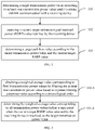
- FIG. 1 which shows a method for calculating a path loss for power control according to an embodiment, the method may include the following steps.
- a target transmission power value is determined according to at least one transmission power value used in unicast sidelink communication with a receiving device.
- the sending device may determine an equivalent target transmission power value according to at least one transmission power value adopted by itself when performing unicast sidelink communication with the receiving device.
- step 102 a current target reference signal received power (RSRP) value returned by the receiving device is received.
- RSRP current target reference signal received power
- the target RSRP is the RSRP value obtained by receiving device through a high layer filtering, for example, layer 3 filtering.
- the receiving device can calculate the target RSRP value using the above formula 1, and return it to the sending device through the sidelink.
- a target path loss value is determined according to the target transmission power value and the current target RSRP value.
- the sending device may determine and obtain the target path loss value according to the determined equivalent target transmission power value and the target RSRP value returned by the receiving device that is currently received.
- the sending device when determining the path loss for power control, can determine one target transmission power value according to at least one transmission power value used in unicast sidelink communication with the receiving device, and then determine the target path loss value according to the target transmission power value and the received current target RSRP value returned by the receiving device, which improves an accuracy of the target path loss value, thereby improving a power control effect of the sidelink communication, which can provide more reliable communication quality for the sidelink communication, and has a higher availability.
- the at least one transmission power value refers to at least one transmission power value of the sending device within a specified time period.
- the specified time period can be determined as the time period from the time point when the target RSRP value returned by the receiving device is received last time to the time point when the current target RSRP value returned by the receiving device is received. That is to say, the time period in which the sending device receives the target RSRP value twice in a row is regarded as the specified time period, and within this specified time period, the equivalent target transmission power value can be determined according to at least one transmission power value sent by the sending device.
- the at least one transmission power value determined by the sender includes at least one transmission power value within the specified time period, and the at least one transmission power value within the specified time period is used to determine the target transmission power value, so that the target transmission power value is more accurate.
- step 101 may include step 101-1.
- step 101-1 the last transmission power value used before the current target RSRP returned by the receiving device is received is determined as the target transmission power value.
- the last transmission power value used before the current target RSRP returned by the receiving device is received is determined as the target transmission power value
- the sending device before receiving the current target RSRP returned by the receiving device, the sending device adopts four transmission power values of P 1 , P 2 , P 3 and P 4 respectively in chronological order, and can directly determine P 4 as the target transmission power value.
- step 101 may include step 101-2.
- step 101-2 an arithmetic mean value of the at least one transmission power value is calculated, and the arithmetic mean value is determined as the target transmission power value.
- the sending device takes the arithmetic mean value of the at least one transmission power value of itself within the specified time period as the target transmission power value.
- step 101 may include steps 101-3 and 101-4.
- a weighted average value corresponding to first N transmission power values is obtained by filtering the at least one transmission power value based on a preset filtering parameter value according to a chronological order.
- the sending device may filter each transmission power value based on the preset filtering parameter value according to the chronological order, to obtain the weighted average value corresponding to first N transmission power values.
- step 101-4 the weighted average value corresponding to all transmission power values before a time point when the current target RSRP value returned by the receiving device is received is determined as the target transmission power value.
- the sending device may take the weighted average value corresponding to all transmission power values within the specified time period as the target transmission power value.
- the sending device has adopted four transmission power values of P 1 , P 2 , P 3 and P 4 in the specified time period.
- a' 1/2
- the weighted average value Q 4 corresponding to all the transmission power values P 1 , P 2 , P 3 and P 4 may be used as the target power value P.
- the last used transmission power value before receiving the current target RSRP value returned by the receiving device, the last used transmission power value may be used as the target transmission power value, or the arithmetic mean value of at least one transmission power value may be directly used as the target transmission power value.
- the weighted average value corresponding to first N transmission power values may be obtained by filtering the at least one transmission power value based on the preset filtering parameter value according to the chronological order, and the weighted average value corresponding to all transmission power values before the time point when the current target RSRP value returned by the receiving device is received may be determined as the target transmission power value.
- the difference between the target transmission power value and the current target RSRP value can be calculated, thereby obtaining the target path loss value, improving the accuracy of the target path loss value, thereby improving the power control effect of the sidelink communication, which can provide more reliable communication quality for the sidelink communication and has a higher availability.
- the present disclosure further provides apparatus embodiments implementing the functions.
- FIG. 3 is a block diagram of an apparatus for calculating a path loss for power control according to an exemplary embodiment
- the apparatus is applied to a sending device of a unicast sidelink communication.
- the apparatus includes a power determining module 210, a receiving module 220 and a path loss determining module 230.
- the power determining module 210 is configured to determine a target transmission power value according to at least one transmission power value used in unicast sidelink communication with a receiving device.
- the receiving module 220 is configured to receive a current target reference signal received power (RSRP) value returned by the receiving device; wherein, the target RSRP value is an RSRP value obtained by the receiving device through high layer filtering.
- RSRP current target reference signal received power
- the path loss determining module 230 is configured to determine a target path loss value according to the target transmission power value and the current target RSRP value.
- the at least one transmission power value includes at least one transmission power value within a specified time period.
- the specified time period includes: a time period from a time point when a last target RSRP value returned by the receiving device is received to a time point when the current target RSRP value returned by the receiving device is received.
- the power determining module 210 includes a first determining submodule 211.
- the first determining submodule 211 is configured to determine a last transmission power value used before the current target RSRP returned by the receiving device is received, as the target transmission power value.
- the power determining module 210 includes a second determining submodule 212.
- the second determining submodule 212 is configured to calculate an arithmetic mean value of the at least one transmission power value, and determine the arithmetic mean value as the target transmission power value.
- the power determining module 210 includes a third determining submodule 213 and a fourth determining submodule 214.
- the third determining submodule 213 is configured to obtain a weighted average value corresponding to first N transmission power values by filtering the at least one transmission power value based on a preset filtering parameter value according to a chronological order.
- the fourth determining submodule 214 is configured to determine the weighted average value corresponding to all transmission power values before a time point when the current target RSRP value returned by the receiving device is received, as the target transmission power value.
- the third determining submodule 213 includes a first calculating unit 2131, a second calculating unit 2132, a third calculating unit 2133 and a fourth calculating unit 2134.
- the first calculating unit 2131 is configured to calculate a first difference between 1 and the filtering parameter value.
- the second calculating unit 2132 is configured to calculate a first product of the first difference and a weighted average corresponding to first (N-1) transmission power values.
- the third calculating unit 2133 is configured to calculate a second product of the filtering parameter value and the Nth transmission power value.
- the fourth calculating unit 2134 is configured to determine the weighted average value corresponding to the first N transmission power values as a sum of the first product and the second product.
- the path loss determining module 203 includes a calculating submodule 231.
- the calculating submodule 231 is configured to obtain the target path loss value by calculating a difference between the target transmission power value and the current target RSRP value.
- the present disclosure further provides an apparatus for calculating a path loss for power control, comprising:
- the apparatus 900 may be provided as a sending device for unicast sidelink communication.
- the apparatus 900 includes a processing component 922, a wireless transmit/receive component 924, an antenna component 926, and a signal processing portion specific to a wireless interface, and the processing component 922 may further include one or more processors.
- One of the processors in the processing component 922 may be configured to perform any of the methods for calculating a path loss for power control described above.
Landscapes
- Engineering & Computer Science (AREA)
- Computer Networks & Wireless Communication (AREA)
- Signal Processing (AREA)
- Physics & Mathematics (AREA)
- Quality & Reliability (AREA)
- Electromagnetism (AREA)
- Probability & Statistics with Applications (AREA)
- Mobile Radio Communication Systems (AREA)
- Cable Transmission Systems, Equalization Of Radio And Reduction Of Echo (AREA)
Abstract
Description
- The disclosure relates to the technical field of wireless communication, and in particular to a method and an apparatus for calculating a path loss for power control.
- At present, in order to avoid interference to uplink communication of a user equipment when the user equipment performs sidelink communication, a transmission power value of the sidelink communication of the user equipment can be controlled according to a size of a downlink path loss. For example, when the user equipment moves to a position farther from a base station, the user equipment can perform the sidelink communication with a higher transmission power value, and when the user equipment moves to a position closer to the base station, the user equipment can perform the sidelink communication with a lower transmission power value. It can be seen that the transmission power value of the user equipment in sidelink communication may be a variable value.
- Since the reference signal power value measured by the user equipment needs to be measured by the high layer, a weighted average of multiple measurement results in a long period of time is required. Different from the process of power control in the uplink communication process, in which the transmission power value of the base station is constant, in sidelink communication, the transmission power value used by the user equipment as the transmitting end is variable, it is difficult to obtain a correct path loss estimate based on the reference signal power value returned by the user equipment as the receiving end after high layer filtering, which will affect the effect of power control in sidelink communication.
- In order to overcome problems existing in the related art, embodiments of the disclosure provide a method and an apparatus for calculating a path loss for power control.
- According to a first aspect of embodiments of the disclosure, a method for calculating a path loss for power control is provided. The method is applied to a sending device of unicast sidelink communication, and includes:
- determining a target transmission power value according to at least one transmission power value used in unicast sidelink communication with a receiving device;
- receiving a current target reference signal received power (RSRP) value returned by the receiving device; wherein, the target RSRP value is an RSRP value obtained by the receiving device through high layer filtering;
- determining a target path loss value according to the target transmission power value and the current target RSRP value.
- Optionally, the at least one transmission power value includes at least one transmission power value within a specified time period.
- Optionally, the specified time period includes:
a time period from a time point when a last target RSRP value returned by the receiving device is received to a time point when the current target RSRP value returned by the receiving device is received. - Optionally, determining the target transmission power value according to at least one transmission power value used in unicast sidelink communication with the receiving device, includes:
calculating an arithmetic mean value of the at least one transmission power value, and determining the arithmetic mean value as the target transmission power value. - Optionally, determining the target transmission power value according to at least one transmission power value used in unicast sidelink communication with the receiving device, includes:
- obtaining a weighted average value corresponding to first N transmission power values by filtering the at least one transmission power value based on a preset filtering parameter value according to a chronological order;
- determining the weighted average value corresponding to all transmission power values before a time point when the current target RSRP value returned by the receiving device is received, as the target transmission power value.
- Optionally, obtaining the weighted average value corresponding to first N transmission power values by filtering the at least one transmission power value based on the preset filtering parameter value according to a chronological order, includes:
- calculating a first difference between 1 and the filtering parameter value;
- calculating a first product of the first difference and a weighted average corresponding to first (N-1) transmission power values;
- calculating a second product of the filtering parameter value and the Nth transmission power value;
- determining the weighted average value corresponding to the first N transmission power values as a sum of the first product and the second product.
- Optionally, determining the target path loss value according to the target transmission power value and the current target RSRP value includes:
obtaining the target path loss value by calculating a difference between the target transmission power value and the current target RSRP value. - According to a second aspect of embodiments of the disclosure, an apparatus for calculating a path loss for power control is provided. The apparatus is applied to a sending device of unicast sidelink communication, and includes:
- a power determining module, configured to determine a target transmission power value according to at least one transmission power value used in unicast sidelink communication with a receiving device;
- a receiving module, configured to receive a current target reference signal received power (RSRP) value returned by the receiving device; wherein, the target RSRP value is an RSRP value obtained by the receiving device through high layer filtering;
- a path loss determining module, configured to determine a target path loss value according to the target transmission power value and the current target RSRP value.
- Optionally, the at least one transmission power value includes at least one transmission power value within a specified time period.
- Optionally, the specified time period includes:
a time period from a time point when a last target RSRP value returned by the receiving device is received to a time point when the current target RSRP value returned by the receiving device is received. - Optionally, the power determining module includes:
a first determining submodule, configured to calculate an arithmetic mean value of the at least one transmission power value, and determine the arithmetic mean value as the target transmission power value. - Optionally, the power determining module includes:
- a second determining submodule, configured to obtain a weighted average value corresponding to first N transmission power values by filtering the at least one transmission power value based on a preset filtering parameter value according to a chronological order;
- a third determining submodule, configured to determine the weighted average value corresponding to all transmission power values before a time point when the current target RSRP value returned by the receiving device is received, as the target transmission power value.
- Optionally, the second determining submodule includes:
- a first calculating unit, configured to calculate a first difference between 1 and the filtering parameter value;
- a second calculating unit, configured to calculate a first product of the first difference and a weighted average corresponding to first (N-1) transmission power values;
- a third calculating unit, configured to calculate a second product of the filtering parameter value and the Nth transmission power value;
- a fourth calculating unit, configured to determine the weighted average value corresponding to the first N transmission power values as a sum of the first product and the second product.
- Optionally, the path loss determining module includes:
a calculating submodule, configured to obtain the target path loss value by calculating a difference between the target transmission power value and the current target RSRP value. - According to a third aspect of embodiments of the disclosure, an apparatus for calculating a path loss for power control is provided, including:
- a processor;
- a memory configured to store instructions executable by the processor,
- wherein the processor is configured to:
- determine a target transmission power value according to at least one transmission power value used in unicast sidelink communication with a receiving device;
- receive a current target reference signal received power (RSRP) value returned by the receiving device; wherein, the target RSRP value is an RSRP value obtained by the receiving device through high layer filtering;
- determine a target path loss value according to the target transmission power value and the current target RSRP value.
- The technical solutions provided by embodiments of the present disclosure may include the following beneficial effects.
- In embodiments of the present disclosure, when determining the path loss for power control, the sending device can determine one target transmission power value according to at least one transmission power value used in unicast sidelink communication with the receiving device, and then determine the target path loss value according to the target transmission power value and the received current target RSRP value returned by the receiving device, which improves an accuracy of the target path loss value, thereby improving a power control effect of the sidelink communication, which can provide more reliable communication quality for the sidelink communication, and has a higher availability.
- In embodiments of the present disclosure, the at least one transmission power value determined by the sender includes at least one transmission power value within a specified time period, and the at least one transmission power value within the specified time period is used to determine the target transmission power value, so that the target transmission power value is more accurate.
- In embodiments of the present disclosure, optionally, the specified time period may be a time period from the time point when a target RSRP value returned by the receiving device is received last to the time point when the current target RSRP value returned by the receiving device is received. The time period between the two times when the receiving device returns the target RSRP value is used as the specified time period, and the availability is high.
- In embodiments of the present disclosure, the last transmission power value used before the current target RSRP value returned by the receiving device is received may be used as the target transmission power value, or the arithmetic mean value of at least one transmission power value may be directly used as the target transmission power value, or the weighted average value corresponding to first N transmission power values may be obtained by filtering the at least one transmission power value based on the preset filtering parameter value according to a chronological order, and the weighted average value corresponding to all transmission power values before a time point when the current target RSRP value returned by the receiving device is received may be determined as the target transmission power value. Through the above ways, one target transmission power value can be determined, and the accuracy of the target path loss value can be improved, thereby improving the power control effect of the sidelink communication, which can provide more reliable communication quality for the sidelink communication, and has a high availability.
- In embodiments of the present disclosure, a first difference between 1 and the filtering parameter value may be calculated first, and then a first product of the first difference and a weighted average corresponding to first (N-1) transmission power values may be calculated, and a second product of the filtering parameter value and the Nth transmission power value may be calculated, and finally a sum of the first product and the second product is determined as weighted average value corresponding to the first N transmission power values. In the above manner, after filtering the at least one transmission power value based on the preset filtering parameter value, the weighted average value corresponding to the first N transmission power values can be obtained respectively, so as to determine the target power value subsequently, which has a high availability.
- In embodiments of the present disclosure, the difference between the target transmission power value and the current target RSRP value can be calculated, so as to obtain the target path loss value, which improves the accuracy of the target path loss value, thereby improving the power control effect of the sidelink communication, which can provide more reliable communication quality for the sidelink communication, and has a high availability.
- It should be understood that the above general description and the following detailed description are only exemplary and explanatory, and cannot limit the disclosure.
- [1] The accompanying drawings, which are incorporated in and constitute a part of this specification, illustrate embodiments consistent with the disclosure and, together with the description, serve to explain the principles of the disclosure.
-
FIG. 1 is a flowchart of a method for calculating a path loss for power control according to an exemplary embodiment. -
FIG. 2 is a flowchart of another method for calculating a path loss for power control according to an exemplary embodiment. -
FIG. 3 is a block diagram of an apparatus for calculating a path loss for power control according to an exemplary embodiment. -
FIG. 4 is a block diagram of another apparatus for calculating a path loss for power control according to an exemplary embodiment. -
FIG. 5 is a block diagram of another apparatus for calculating a path loss for power control according to an exemplary embodiment. -
FIG. 6 is a block diagram of another apparatus for calculating a path loss for power control according to an exemplary embodiment. -
FIG. 7 is a block diagram of another apparatus for calculating a path loss for power control according to an exemplary embodiment. -
FIG. 8 is a block diagram of another apparatus for calculating a path loss for power control according to an exemplary embodiment. -
FIG. 9 is a block diagram of an apparatus for calculating a path loss for power control according to an exemplary embodiment. - Reference will now be made in detail to exemplary embodiments, examples of which are illustrated in the accompanying drawings. The following description refers to the accompanying drawings in which the same numbers in different drawings represent the same or similar elements unless otherwise represented. The implementations set forth in the following description of exemplary embodiments do not represent all implementations consistent with the disclosure. Instead, they are merely examples of apparatuses and methods consistent with aspects related to the disclosure as recited in the appended claims.
- The terms used in the disclosure are only for the purpose of describing specific embodiments, and are not intended to limit the disclosure. The singular forms of "a", "said" and "the" used in the disclosure and appended claims are also intended to include plural forms, unless the context clearly indicates other meanings. It should also be understood that the term "and/or" as used herein refers to and includes any or all possible combinations of one or more associated listed items.
- It should be understood that although the terms first, second, and third may be used in this disclosure to describe various information, the information should not be limited to these terms. These terms are only used to distinguish the same type of information from each other. For example, without departing from the scope of the disclosure, the instruction information may also be referred to as the second information, and similarly, the second information may also be referred to as the instruction information. Depending on the context, the word "if' as used herein can be interpreted as "when", "while" or "in response to determining".
- Embodiment of the present disclosure provide a method for calculating a path loss for power control, which can be applied to a sending device of a unicast sidelink communication. Referring to
FIG. 1 , which shows a method for calculating a path loss for power control according to an embodiment, the method may include the following steps. - In
step 101, a target transmission power value is determined according to at least one transmission power value used in unicast sidelink communication with a receiving device. - In this step, the sending device may determine an equivalent target transmission power value according to at least one transmission power value adopted by itself when performing unicast sidelink communication with the receiving device.
- In
step 102, a current target reference signal received power (RSRP) value returned by the receiving device is received. - The target RSRP is the RSRP value obtained by receiving device through a high layer filtering, for example, layer 3 filtering. The target RSRP value Fn may be calculated using the following formula:

- The receiving device can calculate the target RSRP value using the above formula 1, and return it to the sending device through the sidelink.
- In
step 103, a target path loss value is determined according to the target transmission power value and the current target RSRP value. - In embodiments of the present disclosure, the sending device may determine and obtain the target path loss value according to the determined equivalent target transmission power value and the target RSRP value returned by the receiving device that is currently received.
- In the above-mentioned embodiments, when determining the path loss for power control, the sending device can determine one target transmission power value according to at least one transmission power value used in unicast sidelink communication with the receiving device, and then determine the target path loss value according to the target transmission power value and the received current target RSRP value returned by the receiving device, which improves an accuracy of the target path loss value, thereby improving a power control effect of the sidelink communication, which can provide more reliable communication quality for the sidelink communication, and has a higher availability.
- In an embodiment, the at least one transmission power value refers to at least one transmission power value of the sending device within a specified time period.
- Here, since the target RSRP value obtained by the receiving device through the high layer filtering is a measurement result obtained after a period of time, in order to subsequently improve the accuracy of the target path loss value, the specified time period can be determined as the time period from the time point when the target RSRP value returned by the receiving device is received last time to the time point when the current target RSRP value returned by the receiving device is received. That is to say, the time period in which the sending device receives the target RSRP value twice in a row is regarded as the specified time period, and within this specified time period, the equivalent target transmission power value can be determined according to at least one transmission power value sent by the sending device.
- In the above embodiments, the at least one transmission power value determined by the sender includes at least one transmission power value within the specified time period, and the at least one transmission power value within the specified time period is used to determine the target transmission power value, so that the target transmission power value is more accurate.
- In an embodiment, step 101 may include step 101-1.
- In step 101-1, the last transmission power value used before the current target RSRP returned by the receiving device is received is determined as the target transmission power value.
- In embodiments of the present disclosure, among at least one transmission power value used when the sending device and the receiving device perform unicast sidelink communication, the last transmission power value used before the current target RSRP returned by the receiving device is received is determined as the target transmission power value
- For example, before receiving the current target RSRP returned by the receiving device, the sending device adopts four transmission power values of P1, P2, P3 and P4 respectively in chronological order, and can directly determine P4 as the target transmission power value.
- In an embodiment, step 101 may include step 101-2.
- In step 101-2, an arithmetic mean value of the at least one transmission power value is calculated, and the arithmetic mean value is determined as the target transmission power value.
- The sending device takes the arithmetic mean value of the at least one transmission power value of itself within the specified time period as the target transmission power value.
- For example, within the specified time period, the sending device adopts four transmission power values of P1, P2, P3 and P4 respectively, then the target transmission power value

- In an embodiment, referring to
FIG. 2 , which is a flowchart of another method for calculating a path loss for power control based on the embodiment shown inFIG. 1 , step 101 may include steps 101-3 and 101-4. - In step 101-3, a weighted average value corresponding to first N transmission power values is obtained by filtering the at least one transmission power value based on a preset filtering parameter value according to a chronological order.
- In this step, for the adopted at least one transmission power value, the sending device may filter each transmission power value based on the preset filtering parameter value according to the chronological order, to obtain the weighted average value corresponding to first N transmission power values.
- In step 101-4, the weighted average value corresponding to all transmission power values before a time point when the current target RSRP value returned by the receiving device is received is determined as the target transmission power value.
- In this step, by the time point when the current target RSRP value returned by the receiving device is received, the sending device may take the weighted average value corresponding to all transmission power values within the specified time period as the target transmission power value.
- In an embodiment, the weighted average value Qn corresponding to the first N transmission power values in step 101-3 can be calculated by the following formula:

- For example, according to the chronological order, the sending device has adopted four transmission power values of P1, P2, P3 and P4 in the specified time period. Assuming that a' is 1/2, the corresponding weighted average values are as follows:


- In embodiments of the present disclosure, the weighted average value Q4 corresponding to all the transmission power values P1, P2, P3 and P4 may be used as the target power value P.
- In the above-mentioned embodiments, before receiving the current target RSRP value returned by the receiving device, the last used transmission power value may be used as the target transmission power value, or the arithmetic mean value of at least one transmission power value may be directly used as the target transmission power value. Alternatively, the weighted average value corresponding to first N transmission power values may be obtained by filtering the at least one transmission power value based on the preset filtering parameter value according to the chronological order, and the weighted average value corresponding to all transmission power values before the time point when the current target RSRP value returned by the receiving device is received may be determined as the target transmission power value. Through the above ways, one target transmission power value can be determined, and the accuracy of the target path loss value can be improved, thereby improving the power control effect of the sidelink communication, which can provide more reliable communication quality for the sidelink communication, and has a high availability.
- In an embodiment, for
step 102, the following formula can be used to calculate the target path loss value PL:
- In the above embodiment, the difference between the target transmission power value and the current target RSRP value can be calculated, thereby obtaining the target path loss value, improving the accuracy of the target path loss value, thereby improving the power control effect of the sidelink communication, which can provide more reliable communication quality for the sidelink communication and has a higher availability.
- Corresponding to the foregoing method embodiments implementing functions, the present disclosure further provides apparatus embodiments implementing the functions.
- Referring to
FIG. 3 , which is a block diagram of an apparatus for calculating a path loss for power control according to an exemplary embodiment, the apparatus is applied to a sending device of a unicast sidelink communication. The apparatus includes apower determining module 210, a receivingmodule 220 and a pathloss determining module 230. - The
power determining module 210 is configured to determine a target transmission power value according to at least one transmission power value used in unicast sidelink communication with a receiving device. - The receiving
module 220 is configured to receive a current target reference signal received power (RSRP) value returned by the receiving device; wherein, the target RSRP value is an RSRP value obtained by the receiving device through high layer filtering. - The path
loss determining module 230 is configured to determine a target path loss value according to the target transmission power value and the current target RSRP value. - Optionally, the at least one transmission power value includes at least one transmission power value within a specified time period.
- Optionally, the specified time period includes:
a time period from a time point when a last target RSRP value returned by the receiving device is received to a time point when the current target RSRP value returned by the receiving device is received. - Referring to
FIG. 4 , which is a block diagram of another apparatus for calculating a path loss for power control shown on the basis of the embodiment shown inFIG. 3 , thepower determining module 210 includes a first determiningsubmodule 211. - The first determining
submodule 211 is configured to determine a last transmission power value used before the current target RSRP returned by the receiving device is received, as the target transmission power value. - Referring to
FIG. 5 , which is a block diagram of another apparatus for calculating a path loss for power control shown on the basis of the embodiment shown inFIG. 3 , thepower determining module 210 includes a second determiningsubmodule 212. - The second determining
submodule 212 is configured to calculate an arithmetic mean value of the at least one transmission power value, and determine the arithmetic mean value as the target transmission power value. - Referring to
FIG. 6 , which is a block diagram of another apparatus for calculating a path loss for power control shown on the basis of the embodiment shown inFIG. 3 , thepower determining module 210 includes a third determiningsubmodule 213 and a fourth determiningsubmodule 214. - The third determining
submodule 213 is configured to obtain a weighted average value corresponding to first N transmission power values by filtering the at least one transmission power value based on a preset filtering parameter value according to a chronological order. - The fourth determining
submodule 214 is configured to determine the weighted average value corresponding to all transmission power values before a time point when the current target RSRP value returned by the receiving device is received, as the target transmission power value. - Referring to
FIG. 7 , which is a block diagram of another apparatus for calculating a path loss for power control shown on the basis of the embodiment shown inFIG. 6 , the third determiningsubmodule 213 includes afirst calculating unit 2131, asecond calculating unit 2132, athird calculating unit 2133 and afourth calculating unit 2134. - The
first calculating unit 2131 is configured to calculate a first difference between 1 and the filtering parameter value. - The
second calculating unit 2132 is configured to calculate a first product of the first difference and a weighted average corresponding to first (N-1) transmission power values. - The
third calculating unit 2133 is configured to calculate a second product of the filtering parameter value and the Nth transmission power value. - The
fourth calculating unit 2134 is configured to determine the weighted average value corresponding to the first N transmission power values as a sum of the first product and the second product. - Referring to
FIG. 8 , which is a block diagram of another apparatus for calculating a path loss for power control shown on the basis of the embodiment shown inFIG. 3 , the path loss determining module 203 includes a calculatingsubmodule 231. - The calculating
submodule 231 is configured to obtain the target path loss value by calculating a difference between the target transmission power value and the current target RSRP value. - For the apparatus embodiments, since they basically correspond to the method embodiments, reference may be made to the partial descriptions of the method embodiments for related parts. The apparatus embodiments described above are only illustrative, wherein the units described as separate components may or may not be physically separated, and the components displayed as units may or may not be physical units, that is, they may be located in a local, or may be distributed over multiple network elements. Some or all of the modules can be selected according to actual needs to achieve the purpose of the solution of the present disclosure. Those of ordinary skill in the art can understand and implement it without creative effort.
- Correspondingly, the present disclosure further provides an apparatus for calculating a path loss for power control, comprising:
- a processor;
- a memory configured to store instructions executable by the processor,
- wherein the processor is configured to:
- determine a target transmission power value according to at least one transmission power value used in unicast sidelink communication with a receiving device;
- receive a current target reference signal received power (RSRP) value returned by the receiving device; wherein, the target RSRP value is an RSRP value obtained by the receiving device through high layer filtering;
- determine a target path loss value according to the target transmission power value and the current target RSRP value.
- As shown in
FIG. 9 , which is a block diagram of anapparatus 900 for calculating a path loss for power control according to an exemplary embodiment, theapparatus 900 may be provided as a sending device for unicast sidelink communication. Referring toFIG. 9 , theapparatus 900 includes aprocessing component 922, a wireless transmit/receivecomponent 924, anantenna component 926, and a signal processing portion specific to a wireless interface, and theprocessing component 922 may further include one or more processors. - One of the processors in the
processing component 922 may be configured to perform any of the methods for calculating a path loss for power control described above. - Other embodiments of the disclosure will be apparent to those skilled in the art from consideration of the specification and practice of the disclosure disclosed here. This application is intended to cover any variations, uses, or adaptations of the disclosure following the general principles thereof and including such departures from the disclosure as come within known or customary practice in the art. It is intended that the specification and examples be considered as exemplary only, with a true scope and spirit of the disclosure being indicated by the following claims.
- It will be appreciated that the disclosure is not limited to the exact construction that has been described above and illustrated in the accompanying drawings, and that various modifications and changes can be made without departing from the scope thereof. It is intended that the scope of the disclosure only be limited by the appended claims.
Claims (17)
- A method for calculating a path loss for power control, applied to a sending device of unicast sidelink communication, comprising:determining a target transmission power value according to at least one transmission power value used in unicast sidelink communication with a receiving device;receiving a current target reference signal received power (RSRP) value returned by the receiving device; wherein, the target RSRP value is an RSRP value obtained by the receiving device through high layer filtering;determining a target path loss value according to the target transmission power value and the current target RSRP value.
- The method of claim 1, wherein the at least one transmission power value comprises at least one transmission power value within a specified time period.
- The method of claim 2, wherein the specified time period comprises:
a time period from a time point when a last target RSRP value returned by the receiving device is received to a time point when the current target RSRP value returned by the receiving device is received. - The method of any one of claims 1-3, wherein, determining the target transmission power value according to at least one transmission power value used in unicast sidelink communication with the receiving device, comprises:
determining a last transmission power value used before the current target RSRP returned by the receiving device is received, as the target transmission power value. - The method of any one of claims 1-3, wherein, determining the target transmission power value according to at least one transmission power value used in unicast sidelink communication with the receiving device, comprises:
calculating an arithmetic mean value of the at least one transmission power value, and determining the arithmetic mean value as the target transmission power value. - The method of any one of claims 1-3, wherein, determining the target transmission power value according to at least one transmission power value used in unicast sidelink communication with the receiving device, comprises:obtaining a weighted average value corresponding to first N transmission power values by filtering the at least one transmission power value based on a preset filtering parameter value according to a chronological order;determining the weighted average value corresponding to all transmission power values before a time point when the current target RSRP value returned by the receiving device is received, as the target transmission power value.
- The method of claim 6, wherein obtaining the weighted average value corresponding to first N transmission power values by filtering the at least one transmission power value based on the preset filtering parameter value according to a chronological order comprises:calculating a first difference between 1 and the filtering parameter value;calculating a first product of the first difference and a weighted average corresponding to first (N-1) transmission power values;calculating a second product of the filtering parameter value and the Nth transmission power value;determining the weighted average value corresponding to the first N transmission power values as a sum of the first product and the second product.
- The method of claim 1, wherein determining the target path loss value according to the target transmission power value and the current target RSRP value comprises:
obtaining the target path loss value by calculating a difference between the target transmission power value and the current target RSRP value. - An apparatus for calculating a path loss for power control, applied to a sending device of unicast sidelink communication, comprising:a power determining module, configured to determine a target transmission power value according to at least one transmission power value used in unicast sidelink communication with a receiving device;a receiving module, configured to receive a current target reference signal received power (RSRP) value returned by the receiving device; wherein, the target RSRP value is an RSRP value obtained by the receiving device through high layer filtering;a path loss determining module, configured to determine a target path loss value according to the target transmission power value and the current target RSRP value.
- The apparatus of claim 9, wherein the at least one transmission power value comprises at least one transmission power value within a specified time period.
- The apparatus of claim 10, wherein the specified time period comprises:
a time period from a time point when a last target RSRP value returned by the receiving device is received to a time point when the current target RSRP value returned by the receiving device is received. - The apparatus of any one of claims 9-11, wherein, the power determining module comprises:
a first determining submodule, configured to determine a last transmission power value used before the current target RSRP returned by the receiving device is received, as the target transmission power value. - The apparatus of any one of claims 9-11, wherein, the power determining module comprises:
a second determining submodule, configured to calculate an arithmetic mean value of the at least one transmission power value, and determine the arithmetic mean value as the target transmission power value. - The apparatus of any one of claims 9-11, wherein, the power determining module comprises:a third determining submodule, configured to obtain a weighted average value corresponding to first N transmission power values by filtering the at least one transmission power value based on a preset filtering parameter value according to a chronological order;a fourth determining submodule, configured to determine the weighted average value corresponding to all transmission power values before a time point when the current target RSRP value returned by the receiving device is received, as the target transmission power value.
- The apparatus of claim 14, wherein the third determining submodule comprises:a first calculating unit, configured to calculate a first difference between 1 and the filtering parameter value;a second calculating unit, configured to calculate a first product of the first difference and a weighted average corresponding to first (N-1) transmission power values;a third calculating unit, configured to calculate a second product of the filtering parameter value and the Nth transmission power value;a fourth calculating unit, configured to determine the weighted average value corresponding to the first N transmission power values as a sum of the first product and the second product.
- The apparatus of claim 9, wherein the path loss determining module comprises:
a calculating submodule, configured to obtain the target path loss value by calculating a difference between the target transmission power value and the current target RSRP value. - An apparatus for calculating a path loss for power control, comprising:a processor;a memory configured to store instructions executable by the processor,wherein the processor is configured to:determine a target transmission power value according to at least one transmission power value used in unicast sidelink communication with a receiving device;receive a current target reference signal received power (RSRP) value returned by the receiving device; wherein, the target RSRP value is an RSRP value obtained by the receiving device through high layer filtering;determine a target path loss value according to the target transmission power value and the current target RSRP value.
Applications Claiming Priority (1)
| Application Number | Priority Date | Filing Date | Title |
|---|---|---|---|
| PCT/CN2019/116036 WO2021087815A1 (en) | 2019-11-06 | 2019-11-06 | Path loss calculation method and apparatus for power control |
Publications (2)
| Publication Number | Publication Date |
|---|---|
| EP4057528A1 true EP4057528A1 (en) | 2022-09-14 |
| EP4057528A4 EP4057528A4 (en) | 2022-11-09 |
Family
ID=70080513
Family Applications (1)
| Application Number | Title | Priority Date | Filing Date |
|---|---|---|---|
| EP19951543.8A Pending EP4057528A4 (en) | 2019-11-06 | 2019-11-06 | PROPAGATION LOSS CALCULATION METHOD AND POWER CONTROL APPARATUS |
Country Status (7)
| Country | Link |
|---|---|
| US (1) | US12177789B2 (en) |
| EP (1) | EP4057528A4 (en) |
| JP (1) | JP7385031B2 (en) |
| KR (1) | KR102695588B1 (en) |
| CN (1) | CN110999138B (en) |
| BR (1) | BR112022008349A2 (en) |
| WO (1) | WO2021087815A1 (en) |
Families Citing this family (1)
| Publication number | Priority date | Publication date | Assignee | Title |
|---|---|---|---|---|
| CN120201532B (en) * | 2025-03-17 | 2026-02-13 | 鸿行智芯科技(南京)有限公司 | Unicast power control method, apparatus, device, storage medium and program product |
Family Cites Families (18)
| Publication number | Priority date | Publication date | Assignee | Title |
|---|---|---|---|---|
| JP2008258937A (en) * | 2007-04-05 | 2008-10-23 | Matsushita Electric Ind Co Ltd | Propagation environment estimation method, apparatus, and communication method |
| CN102811478B (en) * | 2011-05-31 | 2016-03-30 | 华为技术有限公司 | A kind of path loss compensation method and base station and subscriber equipment |
| US9241298B2 (en) * | 2011-11-18 | 2016-01-19 | Qualcomm Incorporated | Devices and methods for facilitating access probe sequences |
| CN103379603B (en) | 2012-04-17 | 2016-08-03 | 电信科学技术研究院 | Power control information notice and circule power control method and equipment |
| CN104349443B (en) | 2013-08-09 | 2019-02-12 | 电信科学技术研究院 | A kind of ascending power control method and device |
| WO2015170934A1 (en) * | 2014-05-09 | 2015-11-12 | 주식회사 아이티엘 | Method and apparatus for controlling transmission power in wireless communication system |
| CN110121905B (en) * | 2016-12-30 | 2023-09-22 | 华为技术有限公司 | Path loss estimation methods and devices |
| WO2018144781A1 (en) * | 2017-02-03 | 2018-08-09 | Intel IP Corporation | Rsrp metric for new radio standard |
| CN109257810B (en) | 2017-07-12 | 2022-05-10 | 华为技术有限公司 | A power control method and terminal device |
| CN109392069A (en) * | 2017-08-10 | 2019-02-26 | 中兴通讯股份有限公司 | A kind of Poewr control method and device |
| WO2019127247A1 (en) * | 2017-12-28 | 2019-07-04 | 北京小米移动软件有限公司 | Path loss determination method and apparatus |
| US12213081B2 (en) * | 2018-09-27 | 2025-01-28 | Samsung Electronics Co., Ltd. | Method and device for estimating inter-terminal path loss in wireless communication system |
| WO2020096693A1 (en) * | 2018-11-08 | 2020-05-14 | Convida Wireless, Llc | Sidelink transmit power control for new radio v2x |
| CN117880951A (en) | 2019-08-14 | 2024-04-12 | 北京三星通信技术研究有限公司 | A power control method, device and storage medium for bypass communication system |
| WO2021034245A2 (en) * | 2019-08-16 | 2021-02-25 | Telefonaktiebolaget Lm Ericsson (Publ) | Power control for the sidelink control channel |
| US12127130B2 (en) * | 2019-08-26 | 2024-10-22 | Lg Electronics Inc. | Method and device for determining sidelink transmission power in NR V2X |
| CN114731314B (en) | 2019-09-27 | 2025-07-04 | 日本电气株式会社 | Method, device and computer storage medium for communication |
| WO2021087691A1 (en) * | 2019-11-04 | 2021-05-14 | Oppo广东移动通信有限公司 | Power control method, transmission resource determination method, device, terminal, and medium |
-
2019
- 2019-11-06 BR BR112022008349A patent/BR112022008349A2/en unknown
- 2019-11-06 CN CN201980002883.0A patent/CN110999138B/en active Active
- 2019-11-06 KR KR1020227019011A patent/KR102695588B1/en active Active
- 2019-11-06 EP EP19951543.8A patent/EP4057528A4/en active Pending
- 2019-11-06 US US17/774,369 patent/US12177789B2/en active Active
- 2019-11-06 JP JP2022526228A patent/JP7385031B2/en active Active
- 2019-11-06 WO PCT/CN2019/116036 patent/WO2021087815A1/en not_active Ceased
Also Published As
| Publication number | Publication date |
|---|---|
| KR20220097475A (en) | 2022-07-07 |
| JP7385031B2 (en) | 2023-11-21 |
| JP2023501410A (en) | 2023-01-18 |
| US20220369239A1 (en) | 2022-11-17 |
| CN110999138B (en) | 2022-06-10 |
| BR112022008349A2 (en) | 2022-08-09 |
| EP4057528A4 (en) | 2022-11-09 |
| KR102695588B1 (en) | 2024-08-16 |
| WO2021087815A1 (en) | 2021-05-14 |
| US12177789B2 (en) | 2024-12-24 |
| CN110999138A (en) | 2020-04-10 |
Similar Documents
| Publication | Publication Date | Title |
|---|---|---|
| CN113747344B (en) | Terminal positioning method and device | |
| US12225399B2 (en) | Channel state information transmission method and apparatus | |
| KR102617035B1 (en) | Method and device for positioning using beam information | |
| CN113676830B (en) | Information reporting method, device, equipment and readable storage medium | |
| EP3544323A1 (en) | Method for determining channel time delay, positioning method, and related device | |
| EP3606182B1 (en) | Uplink power control method, device and system | |
| CN107105496B (en) | A kind of method and device, system for obtaining, returning to uplink timing advance | |
| RU2014150510A (en) | METHODS AND DEVICES FOR DETERMINING THE ASSESSMENT OF SIGNAL POWER BY MEASURING ZOOM | |
| EP4195796A1 (en) | Method and apparatus for correcting transmitting channel delay, and storage medium | |
| EP3214884B1 (en) | Method and device for adaptive modulation and coding | |
| CN106888062B (en) | CQI estimation and SINR determination method and related equipment | |
| CN119731551B (en) | Method and device for estimating user equipment positioning based on artificial intelligence | |
| EP2398269A1 (en) | Signal to interference plus noise ratio (sinr) estimation method and device | |
| CN120077291A (en) | Training sample evaluation in positioning | |
| EP4057528A1 (en) | Path loss calculation method and apparatus for power control | |
| US20200374018A1 (en) | Multi-user pairing method and apparatus, and base station | |
| US20130148528A1 (en) | Adaptive modulation and coding scheme selection method and apparatus | |
| CN106973400A (en) | The processing method and UE of a kind of measurement result | |
| EP4420317B1 (en) | Determination of autoregressive model order for a channel prediction filter | |
| RU2795585C1 (en) | Method and apparatus for computing path loss for power control | |
| US12113614B2 (en) | AIML positioning receiver for flexible carrier aggregation | |
| CN120782006A (en) | Data processing method, apparatus, device, storage medium, and program product | |
| CN109413573B (en) | Internet of things terminal positioning method and device | |
| CN121367991A (en) | Positioning assistance data request, transmission method, apparatus, terminal, network device, medium and computer program product | |
| CN118473617A (en) | AIML positioning receiver for flexible carrier aggregation |
Legal Events
| Date | Code | Title | Description |
|---|---|---|---|
| STAA | Information on the status of an ep patent application or granted ep patent |
Free format text: STATUS: THE INTERNATIONAL PUBLICATION HAS BEEN MADE |
|
| PUAI | Public reference made under article 153(3) epc to a published international application that has entered the european phase |
Free format text: ORIGINAL CODE: 0009012 |
|
| STAA | Information on the status of an ep patent application or granted ep patent |
Free format text: STATUS: REQUEST FOR EXAMINATION WAS MADE |
|
| 17P | Request for examination filed |
Effective date: 20220601 |
|
| AK | Designated contracting states |
Kind code of ref document: A1 Designated state(s): AL AT BE BG CH CY CZ DE DK EE ES FI FR GB GR HR HU IE IS IT LI LT LU LV MC MK MT NL NO PL PT RO RS SE SI SK SM TR |
|
| A4 | Supplementary search report drawn up and despatched |
Effective date: 20221007 |
|
| RIC1 | Information provided on ipc code assigned before grant |
Ipc: H04W 52/22 20090101ALI20220930BHEP Ipc: H04W 92/18 20090101ALI20220930BHEP Ipc: H04W 52/38 20090101ALI20220930BHEP Ipc: H04W 52/24 20090101ALI20220930BHEP Ipc: H04W 52/14 20090101ALI20220930BHEP Ipc: H04B 17/309 20150101AFI20220930BHEP |
|
| DAV | Request for validation of the european patent (deleted) | ||
| DAX | Request for extension of the european patent (deleted) | ||
| STAA | Information on the status of an ep patent application or granted ep patent |
Free format text: STATUS: EXAMINATION IS IN PROGRESS |
|
| 17Q | First examination report despatched |
Effective date: 20240419 |