EP4057471A1 - Photovoltaic system, optimizer and method for adjusting working state of optimizer - Google Patents
Photovoltaic system, optimizer and method for adjusting working state of optimizer Download PDFInfo
- Publication number
- EP4057471A1 EP4057471A1 EP20894031.2A EP20894031A EP4057471A1 EP 4057471 A1 EP4057471 A1 EP 4057471A1 EP 20894031 A EP20894031 A EP 20894031A EP 4057471 A1 EP4057471 A1 EP 4057471A1
- Authority
- EP
- European Patent Office
- Prior art keywords
- output
- optimizer
- output port
- state
- controller
- Prior art date
- Legal status (The legal status is an assumption and is not a legal conclusion. Google has not performed a legal analysis and makes no representation as to the accuracy of the status listed.)
- Granted
Links
Images


Classifications
-
- H—ELECTRICITY
- H02—GENERATION; CONVERSION OR DISTRIBUTION OF ELECTRIC POWER
- H02S—GENERATION OF ELECTRIC POWER BY CONVERSION OF INFRARED RADIATION, VISIBLE LIGHT OR ULTRAVIOLET LIGHT, e.g. USING PHOTOVOLTAIC [PV] MODULES
- H02S50/00—Monitoring or testing of PV systems, e.g. load balancing or fault identification
-
- H—ELECTRICITY
- H02—GENERATION; CONVERSION OR DISTRIBUTION OF ELECTRIC POWER
- H02J—ELECTRIC POWER NETWORKS; CIRCUIT ARRANGEMENTS OR SYSTEMS FOR SUPPLYING OR DISTRIBUTING ELECTRIC POWER; SYSTEMS FOR STORING ELECTRIC ENERGY
- H02J3/00—Circuit arrangements for AC mains or AC distribution networks
- H02J3/38—Arrangements for feeding a single network from two or more generators or sources in parallel; Arrangements for feeding already energised networks from additional generators or sources in parallel
- H02J3/381—Dispersed generators
-
- H—ELECTRICITY
- H02—GENERATION; CONVERSION OR DISTRIBUTION OF ELECTRIC POWER
- H02S—GENERATION OF ELECTRIC POWER BY CONVERSION OF INFRARED RADIATION, VISIBLE LIGHT OR ULTRAVIOLET LIGHT, e.g. USING PHOTOVOLTAIC [PV] MODULES
- H02S40/00—Components or accessories in combination with PV modules, not provided for in groups H02S10/00 - H02S30/00
- H02S40/30—Electrical components
-
- H—ELECTRICITY
- H02—GENERATION; CONVERSION OR DISTRIBUTION OF ELECTRIC POWER
- H02J—ELECTRIC POWER NETWORKS; CIRCUIT ARRANGEMENTS OR SYSTEMS FOR SUPPLYING OR DISTRIBUTING ELECTRIC POWER; SYSTEMS FOR STORING ELECTRIC ENERGY
- H02J1/00—Circuit arrangements for DC mains or DC distribution networks
- H02J1/10—Parallel operation of DC sources
- H02J1/106—Parallel operation of DC sources for load balancing, symmetrisation, or sharing
-
- H—ELECTRICITY
- H02—GENERATION; CONVERSION OR DISTRIBUTION OF ELECTRIC POWER
- H02J—ELECTRIC POWER NETWORKS; CIRCUIT ARRANGEMENTS OR SYSTEMS FOR SUPPLYING OR DISTRIBUTING ELECTRIC POWER; SYSTEMS FOR STORING ELECTRIC ENERGY
- H02J2101/00—Supply or distribution of decentralised, dispersed or local electric power generation
- H02J2101/20—Dispersed power generation using renewable energy sources
- H02J2101/22—Solar energy
- H02J2101/24—Photovoltaics
-
- Y—GENERAL TAGGING OF NEW TECHNOLOGICAL DEVELOPMENTS; GENERAL TAGGING OF CROSS-SECTIONAL TECHNOLOGIES SPANNING OVER SEVERAL SECTIONS OF THE IPC; TECHNICAL SUBJECTS COVERED BY FORMER USPC CROSS-REFERENCE ART COLLECTIONS [XRACs] AND DIGESTS
- Y02—TECHNOLOGIES OR APPLICATIONS FOR MITIGATION OR ADAPTATION AGAINST CLIMATE CHANGE
- Y02E—REDUCTION OF GREENHOUSE GAS [GHG] EMISSIONS, RELATED TO ENERGY GENERATION, TRANSMISSION OR DISTRIBUTION
- Y02E10/00—Energy generation through renewable energy sources
- Y02E10/50—Photovoltaic [PV] energy
- Y02E10/56—Power conversion systems, e.g. maximum power point trackers
Definitions
- the present invention relates to the electricity field, and specifically, to a photovoltaic system, an optimizer, and a method for adjusting a working state of an optimizer.
- maximum power tracking and fast shutdown may be implemented at a component level through cooperation between an optimizer and an inverter.
- a typical photovoltaic power system generally includes photovoltaic panels, optimizers, and an inverter.
- An input of the optimizer is connected to an output of the photovoltaic panel.
- the optimizer may track a maximum power of the photovoltaic panel, perform fast shutdown in a special case, monitor a running state of a photovoltaic module, and the like.
- Outputs of a plurality of optimizers are connected in series and then connected to the inverter.
- the inverter imposes a limitation on an input voltage. Therefore, if the input voltage exceeds a maximum input voltage allowed by the inverter, the inverter is damaged.
- the inverter may communicate with the optimizer, and the inverter may read an operating state and a parameter of the optimizer, including an input/output voltage, an input/output current, a power, a temperature, and the like.
- the inverter may adjust the output voltage of the optimizer, to ensure that the input voltage of the inverter does not exceed the maximum input voltage.
- the optimizer cannot communicate with the inverter. In this case, the inverter cannot control the output voltage of the optimizer.
- a default working state of the optimizer is a no-output state or a limited-output state. In this case, it may be ensured that the inverter is not damaged. However, an output of the optimizer is limited, and an output power of the entire photovoltaic system is limited.
- an unlocking apparatus In a process of constructing the photovoltaic power system, an unlocking apparatus needs to be used.
- the photovoltaic panel, the optimizer, and the unlocking apparatus may constitute a photovoltaic system.
- the input of the optimizer is connected to the output of the photovoltaic panel, and the unlocking apparatus is connected to an output of the optimizer.
- the unlocking apparatus may establish communication with the optimizer, and then send an unlocking instruction to the optimizer. After the optimizer receives the unlocking instruction, the optimizer changes the original no-output state or limited-output state to an unlimited-output state. In this way, a limitation on the output of the optimizer may be removed.
- Embodiments of this application provide a photovoltaic system, a method for adjusting a working state of an optimizer, and a controller.
- an unlocking apparatus may not be used.
- the controller may adjust a working state of the optimizer from a no-output state or a limited-output state to an unlimited-output state. In this way, a limitation on an output power of the optimizer may be removed.
- a first aspect of embodiments of this application provides a photovoltaic system.
- the photovoltaic system includes a photovoltaic panel and an optimizer.
- the optimizer includes a controller, a first output port, and a second output port.
- the first output port and the second output port may be directly connected to the controller, or may be connected to the controller by using a sampling circuit.
- the controller is configured to detect an electrical signal parameter between the first output port and the second output port, where the electrical signal parameter is one of a current, a voltage, an output power, or an impedance.
- the controller is configured to adjust a working state of the optimizer from a no-output state or a limited-output state to an unlimited-output state when the electrical signal parameter between the first output port and the second output port changes.
- An output parameter of the optimizer in the no-output state is zero, an output parameter of the optimizer in the limited-output state is below a preset output parameter, and an output parameter of the optimizer in the unlimited-output state is not limited by the preset output parameter.
- the preset output parameter includes one or more of a voltage, a current, and a power.
- the working state of the optimizer can be adjusted without using an unlocking apparatus, to remove a limitation on an output of the optimizer, so that an implementation is simple, and costs are reduced.
- the controller is configured to adjust a working state of the optimizer from a no-output state or a limited-output state to an unlimited-output state when the electrical signal parameter between the first output port and the second output port changes includes: The controller is configured to adjust the working state of the optimizer from the no-output state or the limited-output state to the unlimited-output state when the controller detects that the electrical signal parameter between the first output port and the second output port changes to a value that falls within a preset parameter range.
- the preset parameter range is preset.
- the controller may adjust the working state of the optimizer from the no-output state or the limited-output state to the unlimited-output state when the electrical signal parameter between the first output port and the second output port changes to the value that falls within the preset parameter range. In this way, accuracy of the solution may be improved, and a case in which the electrical signal parameter changes but does not fall within the preset parameter range may be rule out.
- the controller is configured to adjust a working state of the optimizer from a no-output state or a limited-output state to an unlimited-output state when the electrical signal parameter changes includes: The controller is configured to adjust the working state of the optimizer from the no-output state or the limited-output state to the unlimited-output state when the controller detects that a continuous change of the electrical signal parameter between the first output port and the second output port complies with a preset rule.
- the preset rule is preset.
- the controller may adjust the working state of the optimizer from the no-output state or the limited-output state to the unlimited-output state when the continuous change of the electrical signal parameter between the first output port and the second output port complies with the preset rule. In this way, accuracy of the solution may be improved, and a case in which the electrical signal parameter changes but does not change according to the preset rule may be rule out.
- the controller is configured to adjust a working state of the optimizer from a no-output state or a limited-output state to an unlimited-output state when the controller detects that the electrical signal parameter between the first output port and the second output port changes includes: The controller is configured to adjust, after preset time, the working state of the optimizer from the no-output state or the limited-output state to the unlimited-output state when the controller detects that the electrical signal parameter between the first output port and the second output port changes. If the working state is directly changed after the first output port and the second output port are short-circuited, a large short-circuit current may occur. If the two output ports are directly disconnected, a case such as arcing or sparking may occur. The controller changes the working state after the preset time, so that the case such as arcing or sparking can be avoided.
- the electrical signal parameter is an impedance value
- the photovoltaic system further includes an electrical signal parameter conversion unit
- the electrical signal parameter conversion unit includes a first port and a second port, the first port is configured to be connected to the first output port of the optimizer, and the second port is configured to be connected to the second output port of the optimizer.
- the electrical signal parameter conversion unit may change the electrical signal parameter between the first output port and the second output port of the optimizer, so that the controller in the optimizer can detect that the electrical signal parameter changes, and the controller subsequently adjusts the working state of the optimizer from the no-output state or the limited-output state to the unlimited-output state.
- the electrical signal parameter conversion unit includes a first resistor. That the controller is configured to adjust the working state of the optimizer from the no-output state or the limited-output state to the unlimited-output state when the controller detects that the electrical signal parameter between the first output port and the second output port changes to a value that falls within a preset parameter range includes: The controller is configured to adjust the working state of the optimizer from the no-output state or the limited-output state to the unlimited-output state when the controller detects that an impedance value between the first output port and the second output port changes from an impedance value of an internal resistor of the optimizer to an impedance value obtained after the first resistor and the internal resistor of the optimizer are connected in parallel.
- the electrical signal parameter conversion unit includes a second resistor and a first switch.
- the second resistor and the first switch are connected in series.
- an impedance value between the first output port and the second output port is an impedance value of an internal resistor of the optimizer; or when the first switch is closed, an impedance value between the first output port and the second output port is an impedance value obtained after an internal resistor of the optimizer and the second resistor are connected in parallel.
- the electrical signal parameter conversion unit includes a third resistor and a second switch.
- the third resistor and the second switch are connected in parallel.
- an impedance value between the first output port and the second output port is an impedance value obtained after an internal resistor of the optimizer and the third resistor are connected in parallel; or when the second switch is closed, an impedance between the first output port and the second output port is zero.
- That the controller is configured to adjust the working state of the optimizer from the no-output state or the limited-output state to the unlimited-output state when the controller detects that the electrical signal parameter between the first output port and the second output port changes to a value that falls within a preset parameter range includes: The controller is configured to adjust the working state of the optimizer from the no-output state or the limited-output state to the unlimited-output state when the controller detects that the impedance value between the first output port and the second output port changes, to zero, from the impedance value obtained after the third resistor and the internal resistor of the optimizer are connected in parallel.
- a second aspect of this application provides a method for adjusting a working state of an optimizer.
- the method is applied to a photovoltaic system.
- the photovoltaic system includes a photovoltaic panel and an optimizer.
- the optimizer includes a controller, a first output port, and a second output port.
- the method includes: The controller detects an electrical signal parameter between the first output port and the second output port, where the electrical signal parameter is one of a current, a voltage, an output power, or an impedance.
- the controller adjusts a working state of the optimizer from a no-output state or a limited-output state to an unlimited-output state when the electrical signal parameter between the first output port and the second output port changes.
- An output parameter of the optimizer in the no-output state is zero, an output parameter of the optimizer in the limited-output state is below a preset output parameter, and an output parameter of the optimizer in the unlimited-output state is not limited by the preset output parameter.
- the preset output parameter includes one or more of a voltage, a current, and a power.
- the controller adjusts a working state of the optimizer from a no-output state or a limited-output state to an unlimited-output state when the electrical signal parameter between the first output port and the second output port changes includes: The controller adjusts the working state of the optimizer from the no-output state or the limited-output state to the unlimited-output state when the controller detects that a continuous change of the electrical signal parameter between the first output port and the second output port complies with a preset rule.
- the electrical signal parameter is an impedance
- the controller adjusts a working state of the optimizer from a no-output state or a limited-output state to an unlimited-output state when the electrical signal parameter between the first output port and the second output port changes includes: The controller adjusts the working state of the optimizer from the no-output state or the limited-output state to the unlimited-output state when the controller detects that the electrical signal parameter between the first output port and the second output port changes to a value that falls within a preset parameter range.
- a third possible implementation of the second aspect that the controller adjusts a working state of the optimizer from a no-output state or a limited-output state to an unlimited-output state when the controller detects that the electrical signal parameter between the first output port and the second output port changes includes: The controller adjusts, after preset time, the working state of the optimizer from the no-output state or the limited-output state to the unlimited-output state when the controller detects that the electrical signal parameter between the first output port and the second output port changes. If the working state is directly changed after the first output port and the second output port are short-circuited, a large short-circuit current may occur. If the two output ports are directly disconnected, a case such as arcing or sparking may occur. The controller changes the working state after the preset time, so that the case such as arcing or sparking can be avoided.
- a third aspect of this application provides a controller.
- the controller is applied to a photovoltaic system.
- the photovoltaic system includes a photovoltaic panel and an optimizer.
- the optimizer includes a controller, a first output port, and a second output port.
- the controller is configured to detect an electrical signal parameter between the first output port and the second output port, where the electrical signal parameter is one of a current, a voltage, an output power, or an impedance.
- the controller is further configured to adjust a working state of the optimizer from a no-output state or a limited-output state to an unlimited-output state when the electrical signal parameter between the first output port and the second output port changes.
- An output parameter of the optimizer in the no-output state is zero, an output parameter of the optimizer in the limited-output state is below a preset output parameter, and an output parameter of the optimizer in the unlimited-output state is not limited by the preset output parameter.
- the preset output parameter includes one or more of a voltage, a current, and a power.
- the controller is further configured to adjust the working state of the optimizer from the no-output state or the limited-output state to the unlimited-output state when the controller detects that the electrical signal parameter between the first output port and the second output port changes to a value that falls within a preset parameter range.
- the controller is further configured to adjust the working state of the optimizer from the no-output state or the limited-output state to the unlimited-output state when the controller detects that a continuous change of the electrical signal parameter between the first output port and the second output port complies with a preset rule.
- the controller is further configured to adjust, after preset time, the working state of the optimizer from the no-output state or the limited-output state to the unlimited-output state when the controller detects that the electrical signal parameter between the first output port and the second output port changes. If the working state is directly changed after the first output port and the second output port are short-circuited, a large short-circuit current may occur. If the two output ports are directly disconnected, a case such as arcing or sparking may occur. The controller changes the working state after the preset time, so that the case such as arcing or sparking can be avoided.
- a fourth aspect of this application provides an optimizer.
- the optimizer includes a detection module, a first output port, and a second output port. The first output port and the second output port are separately connected to the detection module.
- the detection module is configured to detect an electrical signal parameter between the first output port and the second output port, where the electrical signal parameter is one of a current, a voltage, an output power, or an impedance.
- An adjustment module is configured to adjust a working state of the optimizer from a no-output state or a limited-output state to an unlimited-output state when the detection module detects that the electrical signal parameter between the first output port and the second output port changes.
- An output parameter of the optimizer in the no-output state is zero, an output parameter of the optimizer in the limited-output state is below a preset output parameter, and an output parameter of the optimizer in the unlimited-output state is not limited by the preset output parameter.
- the preset output parameter includes one or more of a voltage, a current, and a power.
- the adjustment module is further configured to adjust the working state of the optimizer from the no-output state or the limited-output state to the unlimited-output state when the control module detects that a continuous change of the electrical signal parameter between the first output port and the second output port complies with a preset rule.
- the adjustment module is further configured to adjust the working state of the optimizer from the no-output state or the limited-output state to the unlimited-output state when the control module detects that the electrical signal parameter between the first output port and the second output port changes to a value that falls within a preset parameter range.
- the adjustment module is further configured to adjust, after preset time, the working state of the optimizer from the no-output state or the limited-output state to the unlimited-output state when the control module detects that the electrical signal parameter between the first output port and the second output port changes. If the working state is directly changed after the first output port and the second output port are short-circuited, a large short-circuit current may occur. If the two output ports are directly disconnected, a case such as arcing or sparking may occur. The controller changes the working state after the preset time, so that the case such as arcing or sparking can be avoided.
- Embodiments of this application provide the photovoltaic system, the method for adjusting a working state of an optimizer, and the controller.
- the photovoltaic system includes the photovoltaic panel and the optimizer.
- the optimizer includes the controller, the first output port, and the second output port.
- the controller is configured to detect the electrical signal parameter between the first output port and the second output port.
- the controller is configured to adjust the working state of the optimizer from the no-output state or the limited-output state to the unlimited-output state when the electrical signal parameter changes.
- the unlocking apparatus may not be used.
- the controller in the optimizer When the controller in the optimizer detects that the electrical signal parameter changes, the controller may adjust the working state of the optimizer from the no-output state or the limited-output state to the unlimited-output state. In this way, a limitation on an output power of the optimizer may be removed.
- a typical photovoltaic power system generally includes a plurality of photovoltaic panels and a plurality of optimizers. Two output terminals of each photovoltaic panel are respectively connected to two input terminals of one optimizer, for example, two output terminals of a photovoltaic plate 110 are connected to two input terminals of an optimizer 120. After output terminals of all the optimizers are connected in series and then connected to two input terminals of an inverter 130, the inverter 130 converts direct current power into alternating current power.
- the optimizer may track a maximum power of the photovoltaic panel, perform fast shutdown in a special case, monitor a running state of a photovoltaic module, and the like.
- An input voltage of the inverter is limited, and a sum of output voltages of the plurality of optimizers shown in FIG. 1 cannot exceed a maximum input voltage allowed by the inverter. Therefore, if the sum exceeds the maximum input voltage allowed by the inverter, the inverter is damaged.
- the inverter may communicate with the optimizer, and the inverter may read an operating state and a parameter of the optimizer, including an input/output voltage, an input/output current, a power, a temperature, and the like. The inverter may adjust the output voltage of the optimizer, to ensure that the sum of the output voltages of all the optimizers does not exceed the maximum input voltage allowed by the inverter.
- the optimizer cannot communicate with the inverter.
- the inverter cannot control the output voltage of the optimizer.
- a default working state of the optimizer is a no-output state or a limited-output state. In this case, it may be ensured that the inverter is not damaged.
- an output of the optimizer is limited, and an output power of the entire photovoltaic system is limited.
- the photovoltaic panel, the optimizer, and the unlocking apparatus may constitute a photovoltaic system.
- the photovoltaic system includes a photovoltaic panel 210, an optimizer 211, and an unlocking apparatus 212.
- An input of the optimizer 211 is connected to an output of the photovoltaic panel 210, and an input of the unlocking apparatus 212 is connected to an output of the optimizer 211.
- the unlocking apparatus 212 may establish communication with the optimizer 211, and then send an unlocking instruction to the optimizer 211. After the optimizer 211 receives the instruction, the optimizer 211 changes an original no-output state or limited-output state to an unlimited-output state. In this way, a limitation on an output power of the optimizer 211 may be removed. However, in such a photovoltaic system, the optimizer 211 needs to use, as a condition, the unlocking instruction sent by the unlocking apparatus 212. When receiving the unlocking instruction sent by the unlocking apparatus, the optimizer changes the original working state such as the no-output state or the limited-output state to the unlimited-output state.
- the output voltage obtained after all the optimizers are connected in series needs to be calculated based on an output voltage of each photovoltaic panel and a quantity of photovoltaic panels, to ensure that after the photovoltaic power system shown in FIG. 1 is finally constructed, the output voltage obtained after all the optimizers are connected in series does not exceed the maximum input voltage allowed by the inverter.
- the optimizer 211 needs to depend on the unlocking apparatus 212, and use, as a condition for changing the working state, the unlocking instruction sent by the unlocking apparatus 212.
- the unlocking apparatus needs to be connected to an optimizer. After the unlocking apparatus sends an unlocking instruction to the optimizer, the optimizer is disconnected from the unlocking apparatus. Then, the unlocking apparatus is connected to another optimizer, and sends an unlocking instruction to the another optimizer. In this way, the unlocking apparatus is transferred between optimizers. If the unlocking apparatus is damaged or abnormal, it is difficult to obtain a new unlocking apparatus immediately. Consequently, a limitation is imposed on an implementation solution for constructing the photovoltaic power system.
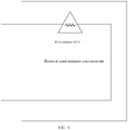
- Embodiment 1 of this application provides a photovoltaic system.
- the photovoltaic system includes a photovoltaic panel 310 and an optimizer 320.
- the optimizer 320 includes a controller 3201, a first output port, and a second output port.
- the first output port and the second output port may be separately connected to the controller 3201, or may be connected to the controller 3201 by using a sampling circuit. This is not limited herein.
- a direct connection is only used as an example in FIG. 3 .
- the controller 3201 is configured to detect an electrical signal parameter between the first output port and the second output port.
- the electrical signal parameter may include one of a voltage, a current, or an impedance. From a process in which the first output port and the second output port are not short-circuited to a process in which the first output port and the second output port are short-circuited, the electrical signal parameter changes.
- the controller is configured to adjust a working state of the optimizer from a no-output state or a limited-output state to an unlimited-output state when the controller 3201 detects that the electrical signal parameter between the first output port and the second output port changes.
- An output parameter of the optimizer in the no-output state is zero, an output parameter of the optimizer in the limited-output state is below a preset output parameter, and an output parameter of the optimizer in the unlimited-output state is not limited by the preset output parameter.
- the preset output parameter includes one or more of a voltage, a current, and a power.
- the controller may immediately change the working state of the optimizer, or may change the working state of the optimizer after preset time. If the working state is directly changed after the first output port and the second output port are short-circuited, a large short-circuit current may occur. If the two output ports are directly disconnected, a case such as arcing or sparking may occur.
- the controller changes the working state after the preset time, so that the case such as arcing or sparking can be avoided. For example, the preset time may be 5 minutes.
- the controller 3201 adjusts the working state of the optimizer from the no-output state or the limited-output state to the unlimited-output state when the controller 3201 detects that the electrical signal parameter between the first output port and the second output port changes to a value that falls within a preset parameter range.
- the controller 3201 detects that the electrical signal parameter between the first output port and the second output port changes to a value that falls within a preset parameter range.
- an impedance value between the first output port and the second output port approaches zero; or when the first output port and the second output port are not short-circuited, an impedance value between the first output port and the second output port is an impedance value of an internal resistor of the optimizer.
- FIG. 3 an example in which the first output port and the second output port are short-circuited is used.
- the impedance is affected by a temperature or another factor.
- a conductor may also have a specified impedance value. Therefore, when the impedance between the first output port and the second output port falls within the preset parameter range, it may be considered that the first output port and the second output port are short-circuited.
- the preset parameter range may be 0 ohms to 1 ohm, and the impedance value of the internal resistor of the optimizer is greater than 1 ohm.
- the controller 3201 may detect that the impedance value between the first output port and the second output port changes from the impedance value of the internal resistor of the optimizer to the value that falls within the preset parameter range.
- the controller 3201 adjusts the working state of the optimizer from the no-output state or the limited-output state to the unlimited-output state.
- the controller 3201 is configured to adjust the working state of the optimizer from the no-output state or the limited-output state to the unlimited-output state when the controller 3201 detects that a continuous change of the electrical signal parameter between the first output port and the second output port complies with a preset rule.
- the controller detects that an impedance value between the first output port and the second output port changes from an impedance value of an internal resistor of the optimizer to a value that approaches zero, then changes to the impedance value of the internal resistor of the optimizer, then changes to the value that approaches zero, and finally changes to the impedance value of the internal resistor of the optimizer.
- the preset rule may be set as follows: The impedance value changes from the impedance value of the internal resistor of the optimizer to the value that approaches zero, then changes to the impedance value of the internal resistor of the optimizer, then changes to the value that approaches zero, and finally changes to the impedance value of the internal resistor of the optimizer.
- the controller 3201 is configured to adjust the working state of the optimizer from the no-output state or the limited-output state to the unlimited-output state when the continuous change of the impedance between the first output port and the second output port complies with the preset rule.
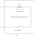
- the photovoltaic system may further include an electrical signal parameter conversion unit.
- the photovoltaic system includes a photovoltaic panel 410, an optimizer 420, and an electrical signal parameter conversion unit 430.
- Two output terminals of the photovoltaic panel 410 are respectively connected to two input terminals of the optimizer 420.
- the optimizer 420 includes a first output port, a second output port, and a controller 4201.
- the controller 4201 is separately connected to the first output port and the second output port.
- Two ports of the electrical signal parameter conversion unit 430 are configured to be connected to the two output ports of the optimizer 420.
- the following provides several specific examples of the electrical signal parameter conversion unit 430.
- FIG. 5 provides an electrical signal parameter conversion unit.
- the electrical signal parameter conversion unit includes a first resistor 4301.
- the impedance value between the first output port and the second output port of the optimizer is an impedance value obtained after the first resistor and the internal resistor of the optimizer are connected in parallel.
- the impedance value between the first output port and the second output port of the optimizer is the impedance value of the internal resistor of the optimizer.
- controller adjusts the working state of the optimizer from the no-output state or the limited-output state to the unlimited-output state when the controller detects that the electrical signal parameter between the first output port and the second output port changes to a value that falls within a preset parameter range
- the controller adjusts the working state of the optimizer from the no-output state or the limited-output state to the unlimited-output state when the controller detects that the impedance value between the first output port and the second output port changes from the impedance value of the internal resistor of the optimizer to the impedance value obtained after the first resistor 4301 and the internal resistor of the optimizer are connected in parallel.
- controller adjusts the working state of the optimizer from the no-output state or the limited-output state to the unlimited-output state when the controller detects that the electrical signal parameter between the first output port and the second output port changes to a value that falls within a preset parameter range
- the controller adjusts the working state of the optimizer from the no-output state or the limited-output state to the unlimited-output state when the controller detects that the impedance value between the first output port and the second output port changes, to the impedance value of the internal resistor of the optimizer, from the impedance value obtained after the first resistor 4301 and the internal resistor of the optimizer are connected in parallel.
- the controller 4201 may further adjust the working state of the optimizer from the no-output state or the limited-output state to the unlimited-output state when the controller 4201 detects that the continuous change of the electrical signal parameter between the first output port and the second output port complies with the preset rule.
- the controller 4201 when the controller 4201 detects that the impedance value between the first output port and the second output port changes from the impedance value of the internal resistor of the optimizer 420 to the impedance value obtained after the internal resistor of the optimizer and the first resistor 4301 are connected in parallel, and then changes to the impedance value of the internal resistor of the optimizer, the controller 4201 adjusts the working state of the optimizer 420 from the no-output state or the limited-output state to the unlimited-output state.
- FIG. 6 provides an electrical signal parameter conversion unit.
- the electrical signal parameter conversion unit includes a second resistor 4302 and a first switch 4303, and the second resistor 4302 and the first switch 4303 are connected in series. Two ports of the electrical signal parameter conversion unit are respectively connected to the first output port and the second output port of the optimizer.
- the impedance value between the first output port and the second output port of the optimizer is an impedance value obtained after the second resistor 4302 and the internal resistor of the optimizer are connected in parallel.
- the impedance value between the first output port and the second output port of the optimizer is the impedance value of the internal resistor of the optimizer.
- that the controller detects that the electrical signal parameter between the first output port and the second output port changes may include: The controller detects that the impedance value between the first output port and the second output port changes from the impedance value of the internal resistor of the optimizer to the impedance value obtained after the internal resistor of the optimizer and the second resistor 4302 are connected in parallel. Alternatively, the controller detects that the impedance value between the first output port and the second output port changes, to the impedance value of the internal resistor of the optimizer, from the impedance value obtained after the internal resistor of the optimizer and the second resistor 4302 are connected in parallel. Alternatively, the controller detects that the impedance between the first output port and the second output port continuously changes according to a preset rule.
- the preset rule may be as follows: The impedance value changes from the impedance value of the internal resistor of the optimizer to the impedance value obtained after the internal resistor of the optimizer and the second resistor 4302 are connected in parallel, and then changes to the impedance value of the internal resistor of the optimizer.
- the controller adjusts the working state of the optimizer from the no-output state or the limited-output state to the unlimited-output state when the controller in the optimizer detects that the electrical signal parameter between the first output port and the second output port changes.
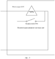
- FIG. 7 provides an electrical signal parameter conversion unit.
- the electrical signal parameter conversion unit includes a third resistor 4305 and a second switch 4306, and the third resistor 4305 and the second switch 4306 are connected in parallel.
- Two ports of the electrical signal parameter conversion unit are respectively connected to the first output port and the second output port of the optimizer.
- the impedance value between the first output port and the second output port of the optimizer is an impedance value obtained after the internal resistor of the optimizer and the third resistor are connected in parallel.
- the second switch is closed, the impedance value between the first output port and the second output port approaches zero.
- that the controller detects that the electrical signal parameter between the first output port and the second output port changes may include: The controller detects that the impedance value between the first output port and the second output port changes, to zero, from the impedance value obtained after the internal resistor of the optimizer and the third resistor 4305 are connected in parallel. Alternatively, the controller detects that the impedance between the first output port and the second output port changes from zero to the impedance value obtained after the internal resistor of the optimizer and the third resistor 4305 are connected in parallel. Alternatively, the controller detects that the impedance between the first output port and the second output port continuously changes according to a preset rule.
- the preset rule may be as follows: The impedance between the first output port and the second output port changes, to zero, from the impedance value obtained after the internal resistor of the optimizer and the third resistor 4305 are connected in parallel, and then changes to the impedance value obtained after the internal resistor of the optimizer and the third resistor 4305 are connected in parallel.
- the controller adjusts the working state of the optimizer from the no-output state or the limited-output state to the unlimited-output state when the controller detects that the electrical signal parameter between the first output port and the second output port changes.
- the controller adjusts the working state of the optimizer from the no-output state or the limited-output state to the unlimited-output state when the controller in the optimizer detects that the electrical signal parameter between the first output port and the second output port of the optimizer changes.
- the working state can be adjusted without using an external unlocking apparatus. Compared with a photovoltaic system in a conventional technology, the photovoltaic system has advantages of simpleness, a low cost, and good availability.
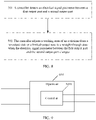
- Embodiment 2 of this application provides a method for adjusting a working state of an optimizer.
- the method is applied to the photovoltaic system provided in Embodiment 1. Referring to FIG. 8 , the method includes the following steps:
- a controller detects an electrical signal parameter between a first output port and a second output port.
- the controller detects the electrical signal parameter between the first output port and the second output port.
- the controller is located in an optimizer, and the controller is separately connected to the first output port and the second output port of the optimizer.
- the electrical signal parameter is one of a voltage, a current, an output power, or an impedance.
- the controller adjusts a working state of the optimizer from a no-output state or a limited-output state to an unlimited-output state when the electrical signal parameter between the first output port and the second output port changes.
- the controller adjusts the working state of the optimizer from the no-output state or the limited-output state to the unlimited-output state when the controller detects that the electrical signal parameter between the first output port and the second output port changes.
- That the controller adjusts the working state of the optimizer from the no-output state or the limited-output state to the unlimited-output state when the controller detects that the electrical signal parameter between the first output port and the second output port changes may include:
- the controller adjusts the working state of the optimizer from the no-output state or the limited-output state to the unlimited-output state when the controller detects that the electrical signal parameter between the first output port and the second output port changes to a value that falls within a preset parameter range or when the controller detects that a continuous change of the electrical signal parameter between the first output port and the second output port complies with a preset rule.
- An output parameter of the optimizer in the no-output state is zero, an output parameter of the optimizer in the limited-output state is below a preset output parameter, and an output parameter of the optimizer in the unlimited-output state is not limited by the preset output parameter.
- the preset output parameter includes one or more of a voltage, a current, and a power.
- the controller may immediately change the working state of the optimizer, or may change the working state of the optimizer after preset time. If the working state is directly changed after the first output port and the second output port are short-circuited, a large short-circuit current may occur. If the two output ports are directly disconnected, a case such as arcing or sparking may occur. The controller changes the working state after the preset time, so that the case such as arcing or sparking can be avoided.
- the working state of the optimizer can be adjusted without using an unlocking apparatus.
- the photovoltaic system has advantages of simpleness, a low cost, and good availability.
- Embodiment 3 of this application provides an optimizer 610.
- the optimizer 610 is located in the photovoltaic system described in Embodiment 1, the optimizer 610 includes a controller 6101 and two output ports, and the controller 6101 is separately connected to the two output ports.
- the controller 6101 is configured to detect an electrical signal parameter between a first output port and a second output port.
- the controller 6101 is further configured to adjust a working state of the optimizer from a no-output state or a limited-output state to an unlimited-output state when the electrical signal parameter between the first output port and the second output port changes.
- the controller 6101 is further configured to adjust the working state of the optimizer from the no-output state or the limited-output state to the unlimited-output state when the controller detects that the electrical signal parameter between the first output port and the second output port changes to a value that falls within a preset parameter range.
- the controller 6101 is further configured to adjust the working state of the optimizer from the no-output state or the limited-output state to the unlimited-output state when the controller detects that a continuous change of the electrical signal parameter between the first output port and the second output port complies with a preset rule.
- Embodiment 4 of this application provides an optimizer 710.
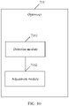
- the optimizer 710 includes a detection module 7101 and an adjustment module 7102.
- the detection module 7101 is configured to detect an electrical signal parameter between a first output port and a second output port of a first optimizer.
- the adjustment module 7102 is configured to adjust a working state of the optimizer from a no-output state or a limited-output state to an unlimited-output state when the detection module detects that the electrical signal parameter between the first output port and the second output port changes.
- the adjustment module 7102 is further configured to adjust the working state of the optimizer from the no-output state or the limited-output state to the unlimited-output state when the control module detects that a continuous change of the electrical signal parameter between the first output port and the second output port complies with a preset rule.
- the adjustment module 7102 is further configured to adjust the working state of the optimizer from the no-output state or the limited-output state to the unlimited-output state when the control module detects that the electrical signal parameter between the first output port and the second output port changes to a value that falls within a preset parameter range.
- the disclosed system, apparatus, and method may be implemented in another manner.
- the described apparatus embodiment is merely an example.
- the module division is merely logical function division and may be other division in an actual implementation.
- a plurality of units or components may be combined or integrated into another system, or some features may be ignored or not performed.
- the displayed or discussed mutual couplings or direct couplings or communication connections may be implemented through some interfaces.
- the indirect couplings or communication connections between the apparatuses or units may be implemented in electrical, mechanical, or other forms.
Landscapes
- Engineering & Computer Science (AREA)
- Power Engineering (AREA)
- Control Of Electrical Variables (AREA)
- Supply And Distribution Of Alternating Current (AREA)
Abstract
Description
- This application claims priority to
Chinese Patent Application No. 201911184561.0, filed with the China National Intellectual Property Administration on November 27, 2019 - The present invention relates to the electricity field, and specifically, to a photovoltaic system, an optimizer, and a method for adjusting a working state of an optimizer.
- In the photovoltaic inverter field, maximum power tracking and fast shutdown may be implemented at a component level through cooperation between an optimizer and an inverter. A typical photovoltaic power system generally includes photovoltaic panels, optimizers, and an inverter. An input of the optimizer is connected to an output of the photovoltaic panel. The optimizer may track a maximum power of the photovoltaic panel, perform fast shutdown in a special case, monitor a running state of a photovoltaic module, and the like. Outputs of a plurality of optimizers are connected in series and then connected to the inverter.
- The inverter imposes a limitation on an input voltage. Therefore, if the input voltage exceeds a maximum input voltage allowed by the inverter, the inverter is damaged. In some scenarios, the inverter may communicate with the optimizer, and the inverter may read an operating state and a parameter of the optimizer, including an input/output voltage, an input/output current, a power, a temperature, and the like. The inverter may adjust the output voltage of the optimizer, to ensure that the input voltage of the inverter does not exceed the maximum input voltage. However, in some other scenarios, the optimizer cannot communicate with the inverter. In this case, the inverter cannot control the output voltage of the optimizer. To ensure that an output voltage obtained after all the optimizers are connected in series does not exceed the maximum input voltage allowed by the inverter, a default working state of the optimizer is a no-output state or a limited-output state. In this case, it may be ensured that the inverter is not damaged. However, an output of the optimizer is limited, and an output power of the entire photovoltaic system is limited.
- In a process of constructing the photovoltaic power system, an unlocking apparatus needs to be used. The photovoltaic panel, the optimizer, and the unlocking apparatus may constitute a photovoltaic system. The input of the optimizer is connected to the output of the photovoltaic panel, and the unlocking apparatus is connected to an output of the optimizer. The unlocking apparatus may establish communication with the optimizer, and then send an unlocking instruction to the optimizer. After the optimizer receives the unlocking instruction, the optimizer changes the original no-output state or limited-output state to an unlimited-output state. In this way, a limitation on the output of the optimizer may be removed.
- Embodiments of this application provide a photovoltaic system, a method for adjusting a working state of an optimizer, and a controller. In the photovoltaic system, an unlocking apparatus may not be used. When a controller in the optimizer detects that an electrical signal parameter changes, the controller may adjust a working state of the optimizer from a no-output state or a limited-output state to an unlimited-output state. In this way, a limitation on an output power of the optimizer may be removed.
- A first aspect of embodiments of this application provides a photovoltaic system. The photovoltaic system includes a photovoltaic panel and an optimizer. The optimizer includes a controller, a first output port, and a second output port. The first output port and the second output port may be directly connected to the controller, or may be connected to the controller by using a sampling circuit. The controller is configured to detect an electrical signal parameter between the first output port and the second output port, where the electrical signal parameter is one of a current, a voltage, an output power, or an impedance. The controller is configured to adjust a working state of the optimizer from a no-output state or a limited-output state to an unlimited-output state when the electrical signal parameter between the first output port and the second output port changes. An output parameter of the optimizer in the no-output state is zero, an output parameter of the optimizer in the limited-output state is below a preset output parameter, and an output parameter of the optimizer in the unlimited-output state is not limited by the preset output parameter. The preset output parameter includes one or more of a voltage, a current, and a power. In the photovoltaic system, the working state of the optimizer can be adjusted without using an unlocking apparatus, to remove a limitation on an output of the optimizer, so that an implementation is simple, and costs are reduced.
- Optionally, with reference to the first aspect, in a first possible implementation of the first aspect, that the controller is configured to adjust a working state of the optimizer from a no-output state or a limited-output state to an unlimited-output state when the electrical signal parameter between the first output port and the second output port changes includes: The controller is configured to adjust the working state of the optimizer from the no-output state or the limited-output state to the unlimited-output state when the controller detects that the electrical signal parameter between the first output port and the second output port changes to a value that falls within a preset parameter range. The preset parameter range is preset. The controller may adjust the working state of the optimizer from the no-output state or the limited-output state to the unlimited-output state when the electrical signal parameter between the first output port and the second output port changes to the value that falls within the preset parameter range. In this way, accuracy of the solution may be improved, and a case in which the electrical signal parameter changes but does not fall within the preset parameter range may be rule out.
- Optionally, with reference to the first aspect, in a second possible implementation of the first aspect, that the controller is configured to adjust a working state of the optimizer from a no-output state or a limited-output state to an unlimited-output state when the electrical signal parameter changes includes: The controller is configured to adjust the working state of the optimizer from the no-output state or the limited-output state to the unlimited-output state when the controller detects that a continuous change of the electrical signal parameter between the first output port and the second output port complies with a preset rule. The preset rule is preset. The controller may adjust the working state of the optimizer from the no-output state or the limited-output state to the unlimited-output state when the continuous change of the electrical signal parameter between the first output port and the second output port complies with the preset rule. In this way, accuracy of the solution may be improved, and a case in which the electrical signal parameter changes but does not change according to the preset rule may be rule out.
- Optionally, with reference to the first aspect to the second possible implementation of the first aspect, in a third possible implementation of the first aspect, that the controller is configured to adjust a working state of the optimizer from a no-output state or a limited-output state to an unlimited-output state when the controller detects that the electrical signal parameter between the first output port and the second output port changes includes: The controller is configured to adjust, after preset time, the working state of the optimizer from the no-output state or the limited-output state to the unlimited-output state when the controller detects that the electrical signal parameter between the first output port and the second output port changes. If the working state is directly changed after the first output port and the second output port are short-circuited, a large short-circuit current may occur. If the two output ports are directly disconnected, a case such as arcing or sparking may occur. The controller changes the working state after the preset time, so that the case such as arcing or sparking can be avoided.
- Optionally, with reference to the third possible implementation of the first aspect, in a fourth possible implementation of the first aspect, the electrical signal parameter is an impedance value, the photovoltaic system further includes an electrical signal parameter conversion unit, the electrical signal parameter conversion unit includes a first port and a second port, the first port is configured to be connected to the first output port of the optimizer, and the second port is configured to be connected to the second output port of the optimizer. The electrical signal parameter conversion unit may change the electrical signal parameter between the first output port and the second output port of the optimizer, so that the controller in the optimizer can detect that the electrical signal parameter changes, and the controller subsequently adjusts the working state of the optimizer from the no-output state or the limited-output state to the unlimited-output state.
- Optionally, with reference to the fourth possible implementation of the first aspect, in a fifth possible implementation of the first aspect, the electrical signal parameter conversion unit includes a first resistor. That the controller is configured to adjust the working state of the optimizer from the no-output state or the limited-output state to the unlimited-output state when the controller detects that the electrical signal parameter between the first output port and the second output port changes to a value that falls within a preset parameter range includes: The controller is configured to adjust the working state of the optimizer from the no-output state or the limited-output state to the unlimited-output state when the controller detects that an impedance value between the first output port and the second output port changes from an impedance value of an internal resistor of the optimizer to an impedance value obtained after the first resistor and the internal resistor of the optimizer are connected in parallel.
- Optionally, with reference to the fourth possible implementation of the first aspect, in a sixth possible implementation of the first aspect, the electrical signal parameter conversion unit includes a second resistor and a first switch. The second resistor and the first switch are connected in series. When the first switch is open, an impedance value between the first output port and the second output port is an impedance value of an internal resistor of the optimizer; or when the first switch is closed, an impedance value between the first output port and the second output port is an impedance value obtained after an internal resistor of the optimizer and the second resistor are connected in parallel. That the controller is configured to adjust the working state of the optimizer from the no-output state or the limited-output state to the unlimited-output state when the controller detects that the electrical signal parameter between the first output port and the second output port changes to a value that falls within a preset parameter range includes: The controller is configured to adjust the working state of the optimizer from the no-output state or the limited-output state to the unlimited-output state when the controller detects that the impedance value between the first output port and the second output port changes from the impedance value of the internal resistor of the optimizer to the impedance value obtained after the first resistor and the internal resistor of the optimizer are connected in parallel.
- Optionally, with reference to the fourth possible implementation of the first aspect, in a seventh possible implementation of the first aspect, the electrical signal parameter conversion unit includes a third resistor and a second switch. The third resistor and the second switch are connected in parallel. When the second switch is open, an impedance value between the first output port and the second output port is an impedance value obtained after an internal resistor of the optimizer and the third resistor are connected in parallel; or when the second switch is closed, an impedance between the first output port and the second output port is zero. That the controller is configured to adjust the working state of the optimizer from the no-output state or the limited-output state to the unlimited-output state when the controller detects that the electrical signal parameter between the first output port and the second output port changes to a value that falls within a preset parameter range includes: The controller is configured to adjust the working state of the optimizer from the no-output state or the limited-output state to the unlimited-output state when the controller detects that the impedance value between the first output port and the second output port changes, to zero, from the impedance value obtained after the third resistor and the internal resistor of the optimizer are connected in parallel.
- A second aspect of this application provides a method for adjusting a working state of an optimizer. The method is applied to a photovoltaic system. The photovoltaic system includes a photovoltaic panel and an optimizer. The optimizer includes a controller, a first output port, and a second output port. The method includes: The controller detects an electrical signal parameter between the first output port and the second output port, where the electrical signal parameter is one of a current, a voltage, an output power, or an impedance. The controller adjusts a working state of the optimizer from a no-output state or a limited-output state to an unlimited-output state when the electrical signal parameter between the first output port and the second output port changes. An output parameter of the optimizer in the no-output state is zero, an output parameter of the optimizer in the limited-output state is below a preset output parameter, and an output parameter of the optimizer in the unlimited-output state is not limited by the preset output parameter. The preset output parameter includes one or more of a voltage, a current, and a power. In the method for adjusting a working state of an optimizer, the photovoltaic system can adjust the working state of the optimizer without using an unlocking apparatus, so that an implementation is simple, and costs are reduced.
- Optionally, with reference to the second aspect, in a first possible implementation of the second aspect, that the controller adjusts a working state of the optimizer from a no-output state or a limited-output state to an unlimited-output state when the electrical signal parameter between the first output port and the second output port changes includes: The controller adjusts the working state of the optimizer from the no-output state or the limited-output state to the unlimited-output state when the controller detects that a continuous change of the electrical signal parameter between the first output port and the second output port complies with a preset rule.
- Optionally, with reference to the second aspect, in a second possible implementation of the second aspect, the electrical signal parameter is an impedance, and that the controller adjusts a working state of the optimizer from a no-output state or a limited-output state to an unlimited-output state when the electrical signal parameter between the first output port and the second output port changes includes: The controller adjusts the working state of the optimizer from the no-output state or the limited-output state to the unlimited-output state when the controller detects that the electrical signal parameter between the first output port and the second output port changes to a value that falls within a preset parameter range.
- Optionally, with reference to any one of the second aspect to the second possible implementation of the second aspect, in a third possible implementation of the second aspect, that the controller adjusts a working state of the optimizer from a no-output state or a limited-output state to an unlimited-output state when the controller detects that the electrical signal parameter between the first output port and the second output port changes includes: The controller adjusts, after preset time, the working state of the optimizer from the no-output state or the limited-output state to the unlimited-output state when the controller detects that the electrical signal parameter between the first output port and the second output port changes. If the working state is directly changed after the first output port and the second output port are short-circuited, a large short-circuit current may occur. If the two output ports are directly disconnected, a case such as arcing or sparking may occur. The controller changes the working state after the preset time, so that the case such as arcing or sparking can be avoided.
- A third aspect of this application provides a controller. The controller is applied to a photovoltaic system. The photovoltaic system includes a photovoltaic panel and an optimizer. The optimizer includes a controller, a first output port, and a second output port. The controller is configured to detect an electrical signal parameter between the first output port and the second output port, where the electrical signal parameter is one of a current, a voltage, an output power, or an impedance. The controller is further configured to adjust a working state of the optimizer from a no-output state or a limited-output state to an unlimited-output state when the electrical signal parameter between the first output port and the second output port changes. An output parameter of the optimizer in the no-output state is zero, an output parameter of the optimizer in the limited-output state is below a preset output parameter, and an output parameter of the optimizer in the unlimited-output state is not limited by the preset output parameter. The preset output parameter includes one or more of a voltage, a current, and a power. The controller adjusts the working state of the optimizer without using an unlocking instruction of an external unlocking apparatus, so that an implementation is simple, and costs are reduced.
- Optionally, with reference to the third aspect, in a first possible implementation of the third aspect, the controller is further configured to adjust the working state of the optimizer from the no-output state or the limited-output state to the unlimited-output state when the controller detects that the electrical signal parameter between the first output port and the second output port changes to a value that falls within a preset parameter range.
- Optionally, with reference to the third aspect, in a second possible implementation of the third aspect, the controller is further configured to adjust the working state of the optimizer from the no-output state or the limited-output state to the unlimited-output state when the controller detects that a continuous change of the electrical signal parameter between the first output port and the second output port complies with a preset rule.
- Optionally, with reference to any one of the third aspect, or the possible implementations of the third aspect, in a third possible implementation of the third aspect, the controller is further configured to adjust, after preset time, the working state of the optimizer from the no-output state or the limited-output state to the unlimited-output state when the controller detects that the electrical signal parameter between the first output port and the second output port changes. If the working state is directly changed after the first output port and the second output port are short-circuited, a large short-circuit current may occur. If the two output ports are directly disconnected, a case such as arcing or sparking may occur. The controller changes the working state after the preset time, so that the case such as arcing or sparking can be avoided.
- A fourth aspect of this application provides an optimizer. The optimizer includes a detection module, a first output port, and a second output port. The first output port and the second output port are separately connected to the detection module. The detection module is configured to detect an electrical signal parameter between the first output port and the second output port, where the electrical signal parameter is one of a current, a voltage, an output power, or an impedance. An adjustment module is configured to adjust a working state of the optimizer from a no-output state or a limited-output state to an unlimited-output state when the detection module detects that the electrical signal parameter between the first output port and the second output port changes. An output parameter of the optimizer in the no-output state is zero, an output parameter of the optimizer in the limited-output state is below a preset output parameter, and an output parameter of the optimizer in the unlimited-output state is not limited by the preset output parameter. The preset output parameter includes one or more of a voltage, a current, and a power. The working state of the optimizer can be adjusted without detecting an external unlocking instruction by the detection module, so that an implementation is simple, and costs are reduced.
- Optionally, with reference to the fourth aspect, in a first possible implementation of the fourth aspect, the adjustment module is further configured to adjust the working state of the optimizer from the no-output state or the limited-output state to the unlimited-output state when the control module detects that a continuous change of the electrical signal parameter between the first output port and the second output port complies with a preset rule.
- Optionally, with reference to the fourth aspect, in a second possible implementation of the fourth aspect, the adjustment module is further configured to adjust the working state of the optimizer from the no-output state or the limited-output state to the unlimited-output state when the control module detects that the electrical signal parameter between the first output port and the second output port changes to a value that falls within a preset parameter range.
- Optionally, with reference to any one of the fourth aspect to the second possible implementation of the fourth aspect, in a third possible implementation of the fourth aspect, the adjustment module is further configured to adjust, after preset time, the working state of the optimizer from the no-output state or the limited-output state to the unlimited-output state when the control module detects that the electrical signal parameter between the first output port and the second output port changes. If the working state is directly changed after the first output port and the second output port are short-circuited, a large short-circuit current may occur. If the two output ports are directly disconnected, a case such as arcing or sparking may occur. The controller changes the working state after the preset time, so that the case such as arcing or sparking can be avoided.
- Embodiments of this application provide the photovoltaic system, the method for adjusting a working state of an optimizer, and the controller. The photovoltaic system includes the photovoltaic panel and the optimizer. The optimizer includes the controller, the first output port, and the second output port. The controller is configured to detect the electrical signal parameter between the first output port and the second output port. The controller is configured to adjust the working state of the optimizer from the no-output state or the limited-output state to the unlimited-output state when the electrical signal parameter changes. In the photovoltaic system, the unlocking apparatus may not be used. When the controller in the optimizer detects that the electrical signal parameter changes, the controller may adjust the working state of the optimizer from the no-output state or the limited-output state to the unlimited-output state. In this way, a limitation on an output power of the optimizer may be removed.
-
-
FIG. 1 is a schematic diagram of a photovoltaic power system architecture according to this application; -
FIG. 2 is a schematic diagram of a photovoltaic system in a conventional technology; -
FIG. 3 is a schematic diagram of an embodiment of a photovoltaic system according to this application; -
FIG. 4 is a schematic diagram of an embodiment of a photovoltaic system according to this application; -
FIG. 5 is a schematic diagram of an embodiment of an electrical signal parameter conversion unit according to this application; -
FIG. 6 is a schematic diagram of an embodiment of an electrical signal parameter conversion unit according to this application; -
FIG. 7 is a schematic diagram of an embodiment of an electrical signal parameter conversion unit according to this application; -
FIG. 8 is a schematic diagram of an embodiment of a method for adjusting a working state of an optimizer according to this application; -
FIG. 9 is a schematic diagram of an embodiment of an optimizer according to this application; and -
FIG. 10 is a schematic diagram of an embodiment of an optimizer according to this application. - The following clearly and completely describes technical solutions in embodiments of the present invention with reference to accompanying drawings in the embodiments of the present invention. It is clear that, the described embodiments are merely a part rather than all of embodiments of the present invention. All other embodiments obtained by a person skilled in the art based on embodiments of the present invention without creative efforts shall fall within the protection scope of the present invention.
- In the specification, claims, and accompanying drawings of this application, the terms "first", "second", and the like are intended to distinguish between similar objects but do not indicate a specific order or sequence. It should be understood that the data used in such a way are interchangeable in proper circumstances so that embodiments described herein can be implemented in other orders than the order illustrated or described herein. In addition, the terms "include", "contain" and any other variants mean to cover the non-exclusive inclusion, for example, a process, method, system, product, or device that includes a list of steps or modules is not necessarily limited to those expressly listed steps or modules, but may include other steps or modules not expressly listed or inherent to such a process, method, system, product, or device.
- In the photovoltaic inverter field, maximum power tracking and fast shutdown may be implemented at a component level through cooperation between an optimizer and an inverter. As shown in
FIG. 1 , a typical photovoltaic power system generally includes a plurality of photovoltaic panels and a plurality of optimizers. Two output terminals of each photovoltaic panel are respectively connected to two input terminals of one optimizer, for example, two output terminals of aphotovoltaic plate 110 are connected to two input terminals of anoptimizer 120. After output terminals of all the optimizers are connected in series and then connected to two input terminals of aninverter 130, theinverter 130 converts direct current power into alternating current power. The optimizer may track a maximum power of the photovoltaic panel, perform fast shutdown in a special case, monitor a running state of a photovoltaic module, and the like. - An input voltage of the inverter is limited, and a sum of output voltages of the plurality of optimizers shown in
FIG. 1 cannot exceed a maximum input voltage allowed by the inverter. Therefore, if the sum exceeds the maximum input voltage allowed by the inverter, the inverter is damaged. In some scenarios, the inverter may communicate with the optimizer, and the inverter may read an operating state and a parameter of the optimizer, including an input/output voltage, an input/output current, a power, a temperature, and the like. The inverter may adjust the output voltage of the optimizer, to ensure that the sum of the output voltages of all the optimizers does not exceed the maximum input voltage allowed by the inverter. However, in some other scenarios, the optimizer cannot communicate with the inverter. In this case, the inverter cannot control the output voltage of the optimizer. To ensure that an output voltage obtained after all the optimizers are connected in series does not exceed the maximum input voltage allowed by the inverter, a default working state of the optimizer is a no-output state or a limited-output state. In this case, it may be ensured that the inverter is not damaged. However, an output of the optimizer is limited, and an output power of the entire photovoltaic system is limited. - Therefore, when the optimizer cannot communicate with the inverter, in a process of constructing the photovoltaic power system shown in
FIG. 1 , after the photovoltaic panel is connected to the optimizer, an unlocking apparatus needs to be used. The photovoltaic panel, the optimizer, and the unlocking apparatus may constitute a photovoltaic system. As shown inFIG. 2 , the photovoltaic system includes aphotovoltaic panel 210, anoptimizer 211, and an unlockingapparatus 212. An input of theoptimizer 211 is connected to an output of thephotovoltaic panel 210, and an input of the unlockingapparatus 212 is connected to an output of theoptimizer 211. The unlockingapparatus 212 may establish communication with theoptimizer 211, and then send an unlocking instruction to theoptimizer 211. After theoptimizer 211 receives the instruction, theoptimizer 211 changes an original no-output state or limited-output state to an unlimited-output state. In this way, a limitation on an output power of theoptimizer 211 may be removed. However, in such a photovoltaic system, theoptimizer 211 needs to use, as a condition, the unlocking instruction sent by the unlockingapparatus 212. When receiving the unlocking instruction sent by the unlocking apparatus, the optimizer changes the original working state such as the no-output state or the limited-output state to the unlimited-output state. - It should be noted that, after the working state of the optimizer changes from the no-output state or the limited-output state to the unlimited-output state, in this solution, the output voltage obtained after all the optimizers are connected in series needs to be calculated based on an output voltage of each photovoltaic panel and a quantity of photovoltaic panels, to ensure that after the photovoltaic power system shown in
FIG. 1 is finally constructed, the output voltage obtained after all the optimizers are connected in series does not exceed the maximum input voltage allowed by the inverter. - In the photovoltaic system shown in
FIG. 2 , theoptimizer 211 needs to depend on the unlockingapparatus 212, and use, as a condition for changing the working state, the unlocking instruction sent by the unlockingapparatus 212. In the process of constructing the photovoltaic power system shown inFIG. 1 , the unlocking apparatus needs to be connected to an optimizer. After the unlocking apparatus sends an unlocking instruction to the optimizer, the optimizer is disconnected from the unlocking apparatus. Then, the unlocking apparatus is connected to another optimizer, and sends an unlocking instruction to the another optimizer. In this way, the unlocking apparatus is transferred between optimizers. If the unlocking apparatus is damaged or abnormal, it is difficult to obtain a new unlocking apparatus immediately. Consequently, a limitation is imposed on an implementation solution for constructing the photovoltaic power system. - Therefore, Embodiment 1 of this application provides a photovoltaic system. As shown in
FIG. 3 , the photovoltaic system includes aphotovoltaic panel 310 and anoptimizer 320. Theoptimizer 320 includes acontroller 3201, a first output port, and a second output port. The first output port and the second output port may be separately connected to thecontroller 3201, or may be connected to thecontroller 3201 by using a sampling circuit. This is not limited herein. A direct connection is only used as an example inFIG. 3 . Thecontroller 3201 is configured to detect an electrical signal parameter between the first output port and the second output port. The electrical signal parameter may include one of a voltage, a current, or an impedance. From a process in which the first output port and the second output port are not short-circuited to a process in which the first output port and the second output port are short-circuited, the electrical signal parameter changes. - The controller is configured to adjust a working state of the optimizer from a no-output state or a limited-output state to an unlimited-output state when the
controller 3201 detects that the electrical signal parameter between the first output port and the second output port changes. An output parameter of the optimizer in the no-output state is zero, an output parameter of the optimizer in the limited-output state is below a preset output parameter, and an output parameter of the optimizer in the unlimited-output state is not limited by the preset output parameter. The preset output parameter includes one or more of a voltage, a current, and a power. - It should be noted that, when the controller detects that the electrical signal parameter between the first output port and the second output port changes, the controller may immediately change the working state of the optimizer, or may change the working state of the optimizer after preset time. If the working state is directly changed after the first output port and the second output port are short-circuited, a large short-circuit current may occur. If the two output ports are directly disconnected, a case such as arcing or sparking may occur. The controller changes the working state after the preset time, so that the case such as arcing or sparking can be avoided. For example, the preset time may be 5 minutes.
- In an implementation, the
controller 3201 adjusts the working state of the optimizer from the no-output state or the limited-output state to the unlimited-output state when thecontroller 3201 detects that the electrical signal parameter between the first output port and the second output port changes to a value that falls within a preset parameter range. It should be noted that, inFIG. 3 , when the first output port and the second output port are short-circuited, an impedance value between the first output port and the second output port approaches zero; or when the first output port and the second output port are not short-circuited, an impedance value between the first output port and the second output port is an impedance value of an internal resistor of the optimizer. InFIG. 3 , an example in which the first output port and the second output port are short-circuited is used. - The impedance is affected by a temperature or another factor. After the first output port and the second output port are short-circuited, a conductor may also have a specified impedance value. Therefore, when the impedance between the first output port and the second output port falls within the preset parameter range, it may be considered that the first output port and the second output port are short-circuited. For example, the preset parameter range may be 0 ohms to 1 ohm, and the impedance value of the internal resistor of the optimizer is greater than 1 ohm.
- Therefore, after the first output port and the second output port are short-circuited, the
controller 3201 may detect that the impedance value between the first output port and the second output port changes from the impedance value of the internal resistor of the optimizer to the value that falls within the preset parameter range. Thecontroller 3201 adjusts the working state of the optimizer from the no-output state or the limited-output state to the unlimited-output state. - In another implementation, the
controller 3201 is configured to adjust the working state of the optimizer from the no-output state or the limited-output state to the unlimited-output state when thecontroller 3201 detects that a continuous change of the electrical signal parameter between the first output port and the second output port complies with a preset rule. For example, when the first output port and the second output port are short-circuited and then disconnected, and are short-circuited again and then disconnected again, the controller detects that an impedance value between the first output port and the second output port changes from an impedance value of an internal resistor of the optimizer to a value that approaches zero, then changes to the impedance value of the internal resistor of the optimizer, then changes to the value that approaches zero, and finally changes to the impedance value of the internal resistor of the optimizer. The preset rule may be set as follows: The impedance value changes from the impedance value of the internal resistor of the optimizer to the value that approaches zero, then changes to the impedance value of the internal resistor of the optimizer, then changes to the value that approaches zero, and finally changes to the impedance value of the internal resistor of the optimizer. Thecontroller 3201 is configured to adjust the working state of the optimizer from the no-output state or the limited-output state to the unlimited-output state when the continuous change of the impedance between the first output port and the second output port complies with the preset rule. - Optionally, the photovoltaic system may further include an electrical signal parameter conversion unit. Referring to
FIG. 4 , the photovoltaic system includes aphotovoltaic panel 410, anoptimizer 420, and an electrical signalparameter conversion unit 430. Two output terminals of thephotovoltaic panel 410 are respectively connected to two input terminals of theoptimizer 420. Theoptimizer 420 includes a first output port, a second output port, and acontroller 4201. Thecontroller 4201 is separately connected to the first output port and the second output port. Two ports of the electrical signalparameter conversion unit 430 are configured to be connected to the two output ports of theoptimizer 420. - The following provides several specific examples of the electrical signal
parameter conversion unit 430. -
FIG. 5 provides an electrical signal parameter conversion unit. The electrical signal parameter conversion unit includes afirst resistor 4301. When two ports of the electrical signal parameter conversion unit are respectively connected to the first output port and the second output port of the optimizer, the impedance value between the first output port and the second output port of the optimizer is an impedance value obtained after the first resistor and the internal resistor of the optimizer are connected in parallel. When two ports of the electrical signal parameter conversion unit are not connected to the first output port and the second output port of the optimizer, the impedance value between the first output port and the second output port of the optimizer is the impedance value of the internal resistor of the optimizer. - For example, that the controller adjusts the working state of the optimizer from the no-output state or the limited-output state to the unlimited-output state when the controller detects that the electrical signal parameter between the first output port and the second output port changes to a value that falls within a preset parameter range may be specifically as follows: The controller adjusts the working state of the optimizer from the no-output state or the limited-output state to the unlimited-output state when the controller detects that the impedance value between the first output port and the second output port changes from the impedance value of the internal resistor of the optimizer to the impedance value obtained after the
first resistor 4301 and the internal resistor of the optimizer are connected in parallel. - Alternatively, that the controller adjusts the working state of the optimizer from the no-output state or the limited-output state to the unlimited-output state when the controller detects that the electrical signal parameter between the first output port and the second output port changes to a value that falls within a preset parameter range may be as follows: The controller adjusts the working state of the optimizer from the no-output state or the limited-output state to the unlimited-output state when the controller detects that the impedance value between the first output port and the second output port changes, to the impedance value of the internal resistor of the optimizer, from the impedance value obtained after the
first resistor 4301 and the internal resistor of the optimizer are connected in parallel. - The
controller 4201 may further adjust the working state of the optimizer from the no-output state or the limited-output state to the unlimited-output state when thecontroller 4201 detects that the continuous change of the electrical signal parameter between the first output port and the second output port complies with the preset rule. For example, when thecontroller 4201 detects that the impedance value between the first output port and the second output port changes from the impedance value of the internal resistor of theoptimizer 420 to the impedance value obtained after the internal resistor of the optimizer and thefirst resistor 4301 are connected in parallel, and then changes to the impedance value of the internal resistor of the optimizer, thecontroller 4201 adjusts the working state of theoptimizer 420 from the no-output state or the limited-output state to the unlimited-output state. -
FIG. 6 provides an electrical signal parameter conversion unit. The electrical signal parameter conversion unit includes asecond resistor 4302 and afirst switch 4303, and thesecond resistor 4302 and thefirst switch 4303 are connected in series. Two ports of the electrical signal parameter conversion unit are respectively connected to the first output port and the second output port of the optimizer. When thefirst switch 4303 is closed, the impedance value between the first output port and the second output port of the optimizer is an impedance value obtained after thesecond resistor 4302 and the internal resistor of the optimizer are connected in parallel. When thefirst switch 4303 is open, the impedance value between the first output port and the second output port of the optimizer is the impedance value of the internal resistor of the optimizer. - For example, that the controller detects that the electrical signal parameter between the first output port and the second output port changes may include: The controller detects that the impedance value between the first output port and the second output port changes from the impedance value of the internal resistor of the optimizer to the impedance value obtained after the internal resistor of the optimizer and the
second resistor 4302 are connected in parallel. Alternatively, the controller detects that the impedance value between the first output port and the second output port changes, to the impedance value of the internal resistor of the optimizer, from the impedance value obtained after the internal resistor of the optimizer and thesecond resistor 4302 are connected in parallel. Alternatively, the controller detects that the impedance between the first output port and the second output port continuously changes according to a preset rule. For example, the preset rule may be as follows: The impedance value changes from the impedance value of the internal resistor of the optimizer to the impedance value obtained after the internal resistor of the optimizer and thesecond resistor 4302 are connected in parallel, and then changes to the impedance value of the internal resistor of the optimizer. The controller adjusts the working state of the optimizer from the no-output state or the limited-output state to the unlimited-output state when the controller in the optimizer detects that the electrical signal parameter between the first output port and the second output port changes. -
FIG. 7 provides an electrical signal parameter conversion unit. The electrical signal parameter conversion unit includes athird resistor 4305 and asecond switch 4306, and thethird resistor 4305 and thesecond switch 4306 are connected in parallel. Two ports of the electrical signal parameter conversion unit are respectively connected to the first output port and the second output port of the optimizer. When the second switch is open, the impedance value between the first output port and the second output port of the optimizer is an impedance value obtained after the internal resistor of the optimizer and the third resistor are connected in parallel. When the second switch is closed, the impedance value between the first output port and the second output port approaches zero. - For example, that the controller detects that the electrical signal parameter between the first output port and the second output port changes may include: The controller detects that the impedance value between the first output port and the second output port changes, to zero, from the impedance value obtained after the internal resistor of the optimizer and the
third resistor 4305 are connected in parallel. Alternatively, the controller detects that the impedance between the first output port and the second output port changes from zero to the impedance value obtained after the internal resistor of the optimizer and thethird resistor 4305 are connected in parallel. Alternatively, the controller detects that the impedance between the first output port and the second output port continuously changes according to a preset rule. For example, the preset rule may be as follows: The impedance between the first output port and the second output port changes, to zero, from the impedance value obtained after the internal resistor of the optimizer and thethird resistor 4305 are connected in parallel, and then changes to the impedance value obtained after the internal resistor of the optimizer and thethird resistor 4305 are connected in parallel. The controller adjusts the working state of the optimizer from the no-output state or the limited-output state to the unlimited-output state when the controller detects that the electrical signal parameter between the first output port and the second output port changes. - In the photovoltaic system provided in Embodiment 1, the controller adjusts the working state of the optimizer from the no-output state or the limited-output state to the unlimited-output state when the controller in the optimizer detects that the electrical signal parameter between the first output port and the second output port of the optimizer changes. In the photovoltaic system, the working state can be adjusted without using an external unlocking apparatus. Compared with a photovoltaic system in a conventional technology, the photovoltaic system has advantages of simpleness, a low cost, and good availability.
- Embodiment 2 of this application provides a method for adjusting a working state of an optimizer. The method is applied to the photovoltaic system provided in Embodiment 1. Referring to
FIG. 8 , the method includes the following steps: - 501. A controller detects an electrical signal parameter between a first output port and a second output port.
- The controller detects the electrical signal parameter between the first output port and the second output port. The controller is located in an optimizer, and the controller is separately connected to the first output port and the second output port of the optimizer. The electrical signal parameter is one of a voltage, a current, an output power, or an impedance.
- 502. The controller adjusts a working state of the optimizer from a no-output state or a limited-output state to an unlimited-output state when the electrical signal parameter between the first output port and the second output port changes.
- The controller adjusts the working state of the optimizer from the no-output state or the limited-output state to the unlimited-output state when the controller detects that the electrical signal parameter between the first output port and the second output port changes.
- That the controller adjusts the working state of the optimizer from the no-output state or the limited-output state to the unlimited-output state when the controller detects that the electrical signal parameter between the first output port and the second output port changes may include:
- The controller adjusts the working state of the optimizer from the no-output state or the limited-output state to the unlimited-output state when the controller detects that the electrical signal parameter between the first output port and the second output port changes to a value that falls within a preset parameter range or when the controller detects that a continuous change of the electrical signal parameter between the first output port and the second output port complies with a preset rule. An output parameter of the optimizer in the no-output state is zero, an output parameter of the optimizer in the limited-output state is below a preset output parameter, and an output parameter of the optimizer in the unlimited-output state is not limited by the preset output parameter. The preset output parameter includes one or more of a voltage, a current, and a power. For details, refer to the related descriptions in Embodiment 1. Details are not described herein again.
- When the controller detects that the electrical signal parameter between the first output port and the second output port changes, the controller may immediately change the working state of the optimizer, or may change the working state of the optimizer after preset time. If the working state is directly changed after the first output port and the second output port are short-circuited, a large short-circuit current may occur. If the two output ports are directly disconnected, a case such as arcing or sparking may occur. The controller changes the working state after the preset time, so that the case such as arcing or sparking can be avoided.
- In the method for adjusting a working state of an optimizer, the working state of the optimizer can be adjusted without using an unlocking apparatus. Compared with a photovoltaic system in a conventional technology, the photovoltaic system has advantages of simpleness, a low cost, and good availability.
- Referring to
FIG. 9 , Embodiment 3 of this application provides anoptimizer 610. Theoptimizer 610 is located in the photovoltaic system described in Embodiment 1, theoptimizer 610 includes acontroller 6101 and two output ports, and thecontroller 6101 is separately connected to the two output ports. - The
controller 6101 is configured to detect an electrical signal parameter between a first output port and a second output port. - The
controller 6101 is further configured to adjust a working state of the optimizer from a no-output state or a limited-output state to an unlimited-output state when the electrical signal parameter between the first output port and the second output port changes. - The
controller 6101 is further configured to adjust the working state of the optimizer from the no-output state or the limited-output state to the unlimited-output state when the controller detects that the electrical signal parameter between the first output port and the second output port changes to a value that falls within a preset parameter range. - The
controller 6101 is further configured to adjust the working state of the optimizer from the no-output state or the limited-output state to the unlimited-output state when the controller detects that a continuous change of the electrical signal parameter between the first output port and the second output port complies with a preset rule. - Referring to
FIG. 10 , Embodiment 4 of this application provides anoptimizer 710. Theoptimizer 710 includes adetection module 7101 and anadjustment module 7102. - The
detection module 7101 is configured to detect an electrical signal parameter between a first output port and a second output port of a first optimizer. - The
adjustment module 7102 is configured to adjust a working state of the optimizer from a no-output state or a limited-output state to an unlimited-output state when the detection module detects that the electrical signal parameter between the first output port and the second output port changes. - The
adjustment module 7102 is further configured to adjust the working state of the optimizer from the no-output state or the limited-output state to the unlimited-output state when the control module detects that a continuous change of the electrical signal parameter between the first output port and the second output port complies with a preset rule. - The
adjustment module 7102 is further configured to adjust the working state of the optimizer from the no-output state or the limited-output state to the unlimited-output state when the control module detects that the electrical signal parameter between the first output port and the second output port changes to a value that falls within a preset parameter range. - It may be clearly understood by a person skilled in the art that, for the purpose of convenient and brief description, for a detailed working process of the foregoing system, apparatus, and module, refer to a corresponding process in the foregoing method embodiments, and details are not described herein again.
- In embodiments provided in this application, it should be understood that the disclosed system, apparatus, and method may be implemented in another manner. For example, the described apparatus embodiment is merely an example. For example, the module division is merely logical function division and may be other division in an actual implementation. For example, a plurality of units or components may be combined or integrated into another system, or some features may be ignored or not performed. In addition, the displayed or discussed mutual couplings or direct couplings or communication connections may be implemented through some interfaces. The indirect couplings or communication connections between the apparatuses or units may be implemented in electrical, mechanical, or other forms.
- The network controller, system, and resource allocation method provided in embodiments of the present invention are described in detail above. The principle and implementations of the present invention are described herein by using specific examples. The description about the embodiments is merely used to help understand the method and core ideas of the present invention. In addition, persons of ordinary skill in the art can make modifications in terms of the specific implementations and application scopes according to the ideas of the present invention. Therefore, the content of specification shall not be construed as a limit to the present invention. Although this application is described in detail with reference to the foregoing embodiments, persons of ordinary skill in the art should understand that they may still make modifications to the technical solutions described in the foregoing embodiments or make equivalent replacements to some technical features thereof, without departing from the spirit and scope of the technical solutions of embodiments of this application.
Claims (23)
- A photovoltaic system, wherein the photovoltaic system comprises an optimizer, and the optimizer comprises a controller, a first output port, and a second output port;the controller is configured to detect an electrical signal parameter between the first output port and the second output port; andthe controller is configured to adjust a working state of the optimizer from a no-output state or a limited-output state to an unlimited-output state when the controller detects that the electrical signal parameter between the first output port and the second output port changes.
- The photovoltaic system according to claim 1, wherein that the controller is configured to adjust a working state of the optimizer from a no-output state or a limited-output state to an unlimited-output state when the controller detects that the electrical signal parameter between the first output port and the second output port changes comprises:
the controller is configured to adjust the working state of the optimizer from the no-output state or the limited-output state to the unlimited-output state when the controller detects that the electrical signal parameter between the first output port and the second output port changes to a value that falls within a preset parameter range. - The photovoltaic system according to claim 1, wherein that the controller is configured to adjust a working state of the optimizer from a no-output state or a limited-output state to an unlimited-output state when the controller detects that the electrical signal parameter between the first output port and the second output port changes comprises:
the controller is configured to adjust the working state of the optimizer from the no-output state or the limited-output state to the unlimited-output state when the controller detects that a continuous change of the electrical signal parameter between the first output port and the second output port complies with a preset rule. - The photovoltaic system according to any one of claims 1 to 3, wherein that the controller is configured to adjust a working state of the optimizer from a no-output state or a limited-output state to an unlimited-output state when the controller detects that the electrical signal parameter between the first output port and the second output port changes comprises:
the controller is configured to adjust, after preset time, the working state of the optimizer from the no-output state or the limited-output state to the unlimited-output state when the controller detects that the electrical signal parameter between the first output port and the second output port changes. - The photovoltaic system according to claim 4, wherein the electrical signal parameter is an impedance value, the photovoltaic system further comprises an electrical signal parameter conversion unit, the electrical signal parameter conversion unit comprises a first port and a second port, the first port is configured to be connected to the first output port of the optimizer, and the second port is configured to be connected to the second output port of the optimizer.
- The photovoltaic system according to claim 5, wherein the electrical signal parameter conversion unit comprises a first resistor; and
that the controller is configured to adjust the working state of the optimizer from the no-output state or the limited-output state to the unlimited-output state when the controller detects that the electrical signal parameter between the first output port and the second output port changes to a value that falls within a preset parameter range comprises:
the controller is configured to adjust the working state of the optimizer from the no-output state or the limited-output state to the unlimited-output state when the controller detects that an impedance value between the first output port and the second output port changes from an impedance value of an internal resistor of the optimizer to an impedance value obtained after the first resistor and the internal resistor of the optimizer are connected in parallel. - The photovoltaic system according to claim 5, wherein the electrical signal parameter conversion unit comprises a second resistor and a first switch; the second resistor and the first switch are connected in series; and when the first switch is open, an impedance value between the first output port and the second output port is an impedance value of an internal resistor of the optimizer; or when the first switch is closed, an impedance value between the first output port and the second output port is an impedance value obtained after an internal resistor of the optimizer and the second resistor are connected in parallel; and
that the controller is configured to adjust the working state of the optimizer from the no-output state or the limited-output state to the unlimited-output state when the controller detects that the electrical signal parameter between the first output port and the second output port changes to a value that falls within a preset parameter range comprises:
the controller is configured to adjust the working state of the optimizer from the no-output state or the limited-output state to the unlimited-output state when the controller detects that the impedance value between the first output port and the second output port changes from the impedance value of the internal resistor of the optimizer to the impedance value obtained after the first resistor and the internal resistor of the optimizer are connected in parallel. - The photovoltaic system according to claim 5, wherein the electrical signal parameter conversion unit comprises a third resistor and a second switch; the third resistor and the second switch are connected in parallel; and when the second switch is open, an impedance value between the first output port and the second output port is an impedance value obtained after an internal resistor of the optimizer and the third resistor are connected in parallel; or when the second switch is closed, an impedance between the first output port and the second output port is zero; and
that the controller is configured to adjust the working state of the optimizer from the no-output state or the limited-output state to the unlimited-output state when the controller detects that the electrical signal parameter between the first output port and the second output port changes to a value that falls within a preset parameter range comprises:
the controller is configured to adjust the working state of the optimizer from the no-output state or the limited-output state to the unlimited-output state when the controller detects that the impedance value between the first output port and the second output port changes, to zero, from the impedance value obtained after the third resistor and the internal resistor of the optimizer are connected in parallel. - A method for adjusting a working state of an optimizer, wherein the method is applied to a photovoltaic system, the photovoltaic system comprises an optimizer, the optimizer comprises a controller, a first output port, and a second output port, and the method comprises:detecting, by the controller, an electrical signal parameter between the first output port and the second output port; andadjusting, by the controller, a working state of the optimizer from a no-output state or a limited-output state to an unlimited-output state when the controller detects that the electrical signal parameter between the first output port and the second output port changes.
- The method according to claim 9, wherein the adjusting, by the controller, a working state of the optimizer from a no-output state or a limited-output state to an unlimited-output state when the controller detects that the electrical signal parameter between the first output port and the second output port changes comprises:
adjusting, by the controller, the working state of the optimizer from the no-output state or the limited-output state to the unlimited-output state when the controller detects that the electrical signal parameter between the first output port and the second output port changes to a value that falls within a preset parameter range. - The method according to claim 9, wherein the adjusting, by the controller, a working state of the optimizer from a no-output state or a limited-output state to an unlimited-output state when the controller detects that the electrical signal parameter between the first output port and the second output port changes comprises:
adjusting, by the controller, the working state of the optimizer from the no-output state or the limited-output state to the unlimited-output state when the controller detects that a continuous change of the electrical signal parameter between the first output port and the second output port complies with a preset rule. - The method according to any one of claims 9 to 11, wherein the adjusting, by the controller, a working state of the optimizer from a no-output state or a limited-output state to an unlimited-output state when the controller detects that the electrical signal parameter between the first output port and the second output port changes comprises:
adjusting, by the controller after preset time, the working state of the optimizer from the no-output state or the limited-output state to the unlimited-output state when the controller detects that the electrical signal parameter between the first output port and the second output port changes. - A controller, wherein the controller is applied to an optimizer, and the optimizer comprises the controller, a first output port, and a second output port;the controller is configured to detect an electrical signal parameter between the first output port and the second output port; andthe controller is further configured to adjust a working state of the optimizer from a no-output state or a limited-output state to an unlimited-output state when the electrical signal parameter between the first output port and the second output port changes.
- The controller according to claim 13, wherein
the controller is further configured to adjust the working state of the optimizer from the no-output state or the limited-output state to the unlimited-output state when the controller detects that the electrical signal parameter between the first output port and the second output port changes to a value that falls within a preset parameter range. - The controller according to claim 13, wherein
the controller is further configured to adjust the working state of the optimizer from the no-output state or the limited-output state to the unlimited-output state when the controller detects that a continuous change of the electrical signal parameter between the first output port and the second output port complies with a preset rule. - The controller according to any one of claims 13 to 15, wherein
the controller is further configured to adjust, after preset time, the working state of the optimizer from the no-output state or the limited-output state to the unlimited-output state when the controller detects that the electrical signal parameter between the first output port and the second output port changes. - An optimizer, wherein the optimizer comprises:a detection module, configured to detect an electrical signal parameter between a first output port and a second output port of the optimizer; andan adjustment module, configured to adjust a working state of the optimizer from a no-output state or a limited-output state to an unlimited-output state when the detection module detects that the electrical signal parameter between the first output port and the second output port changes.
- The controller according to claim 17, wherein
the adjustment module is further configured to adjust the working state of the optimizer from the no-output state or the limited-output state to the unlimited-output state when the control module detects that the electrical signal parameter between the first output port and the second output port changes to a value that falls within a preset parameter range. - The optimizer according to claim 17, wherein
the adjustment module is further configured to adjust the working state of the optimizer from the no-output state or the limited-output state to the unlimited-output state when the control module detects that a continuous change of the electrical signal parameter between the first output port and the second output port complies with a preset rule. - The optimizer according to any one of claims 17 to 19, wherein
the adjustment module is further configured to adjust, after preset time, the working state of the optimizer from the no-output state or the limited-output state to the unlimited-output state when the control module detects that the electrical signal parameter between the first output port and the second output port changes. - A computer program product, wherein the computer program product comprises computer program instructions, and when the computer program instructions are run on a computer, the computer is enabled to perform the method for adjusting a working state of an optimizer according to any one of claims 9 to 12.
- A computer-readable storage medium, configured to store computer program instructions, wherein when the computer program instructions are run on a computer, the computer is enabled to perform the method for adjusting a working state of an optimizer according to any one of claims 9 to 12.
- A chip, wherein the chip comprises a processor, and the processor is configured to execute computer program instructions stored in a memory, to perform the method for adjusting a working state of an optimizer according to any one of claims 9 to 12.
Applications Claiming Priority (2)
| Application Number | Priority Date | Filing Date | Title |
|---|---|---|---|
| CN201911184561.0A CN110957760B (en) | 2019-11-27 | 2019-11-27 | Photovoltaic system, optimizer and working state adjusting method of optimizer |
| PCT/CN2020/099081 WO2021103524A1 (en) | 2019-11-27 | 2020-06-30 | Photovoltaic system, optimizer and method for adjusting working state of optimizer |
Publications (3)
| Publication Number | Publication Date |
|---|---|
| EP4057471A1 true EP4057471A1 (en) | 2022-09-14 |
| EP4057471A4 EP4057471A4 (en) | 2023-03-15 |
| EP4057471B1 EP4057471B1 (en) | 2025-12-31 |
Family
ID=69978638
Family Applications (1)
| Application Number | Title | Priority Date | Filing Date |
|---|---|---|---|
| EP20894031.2A Active EP4057471B1 (en) | 2019-11-27 | 2020-06-30 | PHOTOVOLTAIC SYSTEM AND METHOD FOR SETTING AN OPTIMIZER'S OPERATING STATE |
Country Status (5)
| Country | Link |
|---|---|
| US (1) | US12009665B2 (en) |
| EP (1) | EP4057471B1 (en) |
| JP (1) | JP7419530B2 (en) |
| CN (2) | CN110957760B (en) |
| WO (1) | WO2021103524A1 (en) |
Families Citing this family (4)
| Publication number | Priority date | Publication date | Assignee | Title |
|---|---|---|---|---|
| CN110957760B (en) * | 2019-11-27 | 2022-08-26 | 华为数字能源技术有限公司 | Photovoltaic system, optimizer and working state adjusting method of optimizer |
| CN111864802B (en) * | 2020-08-12 | 2022-05-24 | 阳光电源股份有限公司 | Photovoltaic system direct current side power electronic equipment and testing system and control method thereof |
| US12479150B2 (en) | 2020-09-17 | 2025-11-25 | Guangzhou Tech-Long Packaging Machinery Co., Ltd | Bottle blowing mold, bottle blowing machine and plastic bottle |
| CN112332536B (en) * | 2020-10-22 | 2023-03-31 | 阳光电源股份有限公司 | Photovoltaic system turn-off control method, device and system |
Family Cites Families (19)
| Publication number | Priority date | Publication date | Assignee | Title |
|---|---|---|---|---|
| JPH0669273B2 (en) * | 1989-01-26 | 1994-08-31 | 日本電気株式会社 | Power board |
| EP1798845A1 (en) | 2005-12-16 | 2007-06-20 | Advanced Digital Broadcast S.A. | Multi-output switched-mode power supply |
| US8013474B2 (en) * | 2006-11-27 | 2011-09-06 | Xslent Energy Technologies, Llc | System and apparatuses with multiple power extractors coupled to different power sources |
| EP2109927B1 (en) | 2007-02-06 | 2021-11-17 | Apparent Labs, LLC | Multi-source, multi-load systems with a power extractor |
| CN102291052B (en) | 2011-08-22 | 2014-01-22 | 浙江昱能光伏科技集成有限公司 | Solar photovoltaic system as well as energy collecting and optimizing method and fault detecting method thereof |
| CN102983788A (en) * | 2012-08-17 | 2013-03-20 | 苏州嘉亿睿耘科技有限公司 | Self-coordination photovoltaic component optimizer |
| CN105474406A (en) | 2013-04-13 | 2016-04-06 | 速力斯公司 | Smart photovoltaic cells and modules |
| JP6330229B2 (en) | 2014-10-28 | 2018-05-30 | 本田技研工業株式会社 | Charge / discharge system |
| WO2017087988A1 (en) | 2015-11-19 | 2017-05-26 | Beamreach Solar, Inc. | Multi-modal maximum power point tracking optimzation solar photovoltaic system |
| CN106300433B (en) * | 2016-11-10 | 2019-08-13 | 阳光电源股份有限公司 | Coordinated control method and device for photovoltaic optimizer and photovoltaic inverter |
| JP6658582B2 (en) | 2017-01-31 | 2020-03-04 | オムロン株式会社 | Arc detector |
| CN107154780B (en) * | 2017-06-08 | 2019-04-09 | 阳光电源股份有限公司 | A photovoltaic power generation system and its power control method and power optimizer |
| CN109428545B (en) * | 2017-09-04 | 2020-11-27 | 丰郅(上海)新能源科技有限公司 | Method for switching power optimizer of photovoltaic module between different working modes |
| CN110391671B (en) * | 2018-04-23 | 2023-03-10 | 台达电子工业股份有限公司 | Optimizer, control method and parallel structure for photovoltaic inverter system |
| CN109193777B (en) * | 2018-10-12 | 2022-05-24 | 阳光电源股份有限公司 | Power optimizer and photovoltaic power generation system |
| CN109831107B (en) * | 2019-02-28 | 2021-06-22 | 华为技术有限公司 | A power conversion device and a method for controlling the output impedance of the power conversion device |
| CN109787289B (en) | 2019-03-15 | 2021-08-13 | 矽力杰半导体技术(杭州)有限公司 | Power conversion system, photovoltaic optimizer and power tracking method |
| CN109787290B (en) | 2019-03-19 | 2022-03-25 | 矽力杰半导体技术(杭州)有限公司 | Photovoltaic system and control circuit and control method thereof |
| CN110957760B (en) * | 2019-11-27 | 2022-08-26 | 华为数字能源技术有限公司 | Photovoltaic system, optimizer and working state adjusting method of optimizer |
-
2019
- 2019-11-27 CN CN201911184561.0A patent/CN110957760B/en active Active
- 2019-11-27 CN CN202211008118.XA patent/CN115411769A/en active Pending
-
2020
- 2020-06-30 JP JP2022530989A patent/JP7419530B2/en active Active
- 2020-06-30 EP EP20894031.2A patent/EP4057471B1/en active Active
- 2020-06-30 WO PCT/CN2020/099081 patent/WO2021103524A1/en not_active Ceased
-
2022
- 2022-05-26 US US17/825,108 patent/US12009665B2/en active Active
Also Published As
| Publication number | Publication date |
|---|---|
| CN115411769A (en) | 2022-11-29 |
| EP4057471B1 (en) | 2025-12-31 |
| JP2023504058A (en) | 2023-02-01 |
| EP4057471A4 (en) | 2023-03-15 |
| US12009665B2 (en) | 2024-06-11 |
| CN110957760B (en) | 2022-08-26 |
| US20220285948A1 (en) | 2022-09-08 |
| JP7419530B2 (en) | 2024-01-22 |
| WO2021103524A1 (en) | 2021-06-03 |
| CN110957760A (en) | 2020-04-03 |
Similar Documents
| Publication | Publication Date | Title |
|---|---|---|
| US12009665B2 (en) | Photovoltaic system, optimizer, and method for adjusting working state of optimizer | |
| US9954369B2 (en) | Power supply method and apparatus | |
| US10503126B2 (en) | Access control method for parallel direct current power supplies and device thereof | |
| EP3309920B1 (en) | Method and device for voltage balance | |
| US20130162196A1 (en) | Charger | |
| US20160336779A1 (en) | Charging Method, Alternating Current Adaptor, Charging Management Device and Terminal | |
| CN205509651U (en) | UPS cabinet | |
| US12355276B2 (en) | Power supply system and method of server, electronic device, and storage medium | |
| US9923368B2 (en) | Electronic apparatus and driving control method thereof | |
| US10079688B2 (en) | Network port and ethernet device integrating powered device and power sourcing equivalent in a port | |
| US20120235480A1 (en) | Uninterrupted power supply system and uninterrupted power supply device | |
| CN103176100A (en) | Method and device for detecting whether storage battery is normally connected in UPS (uninterrupted power supply) or not | |
| CN112134270A (en) | DC power supply system and control method thereof | |
| CN114094692B (en) | Power supply system and method for substation equipment | |
| CN111337823B (en) | Relay failure detection device and method | |
| US20250079866A1 (en) | Energy storage device, method for energy storage device to determine whether converter device connected thereto has neutral line, and power supply system | |
| CN106972558B (en) | Charging control method and electronic equipment | |
| JP2014067340A (en) | Pv panel diagnostic device, diagnostic method, diagnostic program and impedance adjusting circuit | |
| CN107706977A (en) | Method for detecting charging current and charging device | |
| US20240377474A1 (en) | Fault detection method and apparatus for three phase power supply circuit of frequency converter, and air conditioner | |
| CN115420942A (en) | Electric energy measuring device and power supply system | |
| KR101199934B1 (en) | Power Supply Apparatus with Variable Output | |
| CN103117590A (en) | Uninterruptible Power Supply System with Simplified Voltage Detection Circuit | |
| CN113675858A (en) | Reactive compensation control method and device, storage medium and equipment | |
| CN106020304A (en) | Self-adaptive master slave multimode type parallel operation current-sharing control method |
Legal Events
| Date | Code | Title | Description |
|---|---|---|---|
| STAA | Information on the status of an ep patent application or granted ep patent |
Free format text: STATUS: THE INTERNATIONAL PUBLICATION HAS BEEN MADE |
|
| PUAI | Public reference made under article 153(3) epc to a published international application that has entered the european phase |
Free format text: ORIGINAL CODE: 0009012 |
|
| STAA | Information on the status of an ep patent application or granted ep patent |
Free format text: STATUS: REQUEST FOR EXAMINATION WAS MADE |
|
| 17P | Request for examination filed |
Effective date: 20220609 |
|
| AK | Designated contracting states |
Kind code of ref document: A1 Designated state(s): AL AT BE BG CH CY CZ DE DK EE ES FI FR GB GR HR HU IE IS IT LI LT LU LV MC MK MT NL NO PL PT RO RS SE SI SK SM TR |
|
| DAV | Request for validation of the european patent (deleted) | ||
| DAX | Request for extension of the european patent (deleted) | ||
| A4 | Supplementary search report drawn up and despatched |
Effective date: 20230209 |
|
| RIC1 | Information provided on ipc code assigned before grant |
Ipc: H02J 1/10 20060101ALN20230203BHEP Ipc: H02S 50/00 20140101ALI20230203BHEP Ipc: H02J 3/38 20060101AFI20230203BHEP |
|
| STAA | Information on the status of an ep patent application or granted ep patent |
Free format text: STATUS: EXAMINATION IS IN PROGRESS |
|
| 17Q | First examination report despatched |
Effective date: 20231108 |
|
| GRAP | Despatch of communication of intention to grant a patent |
Free format text: ORIGINAL CODE: EPIDOSNIGR1 |
|
| STAA | Information on the status of an ep patent application or granted ep patent |
Free format text: STATUS: GRANT OF PATENT IS INTENDED |
|
| RIC1 | Information provided on ipc code assigned before grant |
Ipc: H02J 3/38 20060101AFI20250813BHEP Ipc: H02S 50/00 20140101ALI20250813BHEP Ipc: H02J 1/10 20060101ALN20250813BHEP |
|
| INTG | Intention to grant announced |
Effective date: 20250826 |
|
| GRAS | Grant fee paid |
Free format text: ORIGINAL CODE: EPIDOSNIGR3 |
|
| GRAA | (expected) grant |
Free format text: ORIGINAL CODE: 0009210 |
|
| STAA | Information on the status of an ep patent application or granted ep patent |
Free format text: STATUS: THE PATENT HAS BEEN GRANTED |
|
| AK | Designated contracting states |
Kind code of ref document: B1 Designated state(s): AL AT BE BG CH CY CZ DE DK EE ES FI FR GB GR HR HU IE IS IT LI LT LU LV MC MK MT NL NO PL PT RO RS SE SI SK SM TR |
|
| REG | Reference to a national code |
Ref country code: CH Ref legal event code: F10 Free format text: ST27 STATUS EVENT CODE: U-0-0-F10-F00 (AS PROVIDED BY THE NATIONAL OFFICE) Effective date: 20251231 Ref country code: GB Ref legal event code: FG4D |
|
| REG | Reference to a national code |
Ref country code: DE Ref legal event code: R096 Ref document number: 602020064961 Country of ref document: DE |
|
| REG | Reference to a national code |
Ref country code: IE Ref legal event code: FG4D |
|
| REG | Reference to a national code |
Ref country code: LT Ref legal event code: MG9D |
|
| PG25 | Lapsed in a contracting state [announced via postgrant information from national office to epo] |
Ref country code: NO Free format text: LAPSE BECAUSE OF FAILURE TO SUBMIT A TRANSLATION OF THE DESCRIPTION OR TO PAY THE FEE WITHIN THE PRESCRIBED TIME-LIMIT Effective date: 20260331 |
|
| PG25 | Lapsed in a contracting state [announced via postgrant information from national office to epo] |
Ref country code: HR Free format text: LAPSE BECAUSE OF FAILURE TO SUBMIT A TRANSLATION OF THE DESCRIPTION OR TO PAY THE FEE WITHIN THE PRESCRIBED TIME-LIMIT Effective date: 20251231 Ref country code: FI Free format text: LAPSE BECAUSE OF FAILURE TO SUBMIT A TRANSLATION OF THE DESCRIPTION OR TO PAY THE FEE WITHIN THE PRESCRIBED TIME-LIMIT Effective date: 20251231 |
|
| PG25 | Lapsed in a contracting state [announced via postgrant information from national office to epo] |
Ref country code: RS Free format text: LAPSE BECAUSE OF FAILURE TO SUBMIT A TRANSLATION OF THE DESCRIPTION OR TO PAY THE FEE WITHIN THE PRESCRIBED TIME-LIMIT Effective date: 20260331 |
|
| PG25 | Lapsed in a contracting state [announced via postgrant information from national office to epo] |
Ref country code: LV Free format text: LAPSE BECAUSE OF FAILURE TO SUBMIT A TRANSLATION OF THE DESCRIPTION OR TO PAY THE FEE WITHIN THE PRESCRIBED TIME-LIMIT Effective date: 20251231 |