EP4057468A1 - Control method, computer program product, control system & use - Google Patents
Control method, computer program product, control system & use Download PDFInfo
- Publication number
- EP4057468A1 EP4057468A1 EP21162435.8A EP21162435A EP4057468A1 EP 4057468 A1 EP4057468 A1 EP 4057468A1 EP 21162435 A EP21162435 A EP 21162435A EP 4057468 A1 EP4057468 A1 EP 4057468A1
- Authority
- EP
- European Patent Office
- Prior art keywords
- output voltage
- power
- grid frequency
- power grid
- control system
- Prior art date
- Legal status (The legal status is an assumption and is not a legal conclusion. Google has not performed a legal analysis and makes no representation as to the accuracy of the status listed.)
- Withdrawn
Links
Images


Classifications
-
- H—ELECTRICITY
- H02—GENERATION; CONVERSION OR DISTRIBUTION OF ELECTRIC POWER
- H02J—ELECTRIC POWER NETWORKS; CIRCUIT ARRANGEMENTS OR SYSTEMS FOR SUPPLYING OR DISTRIBUTING ELECTRIC POWER; SYSTEMS FOR STORING ELECTRIC ENERGY
- H02J3/00—Circuit arrangements for AC mains or AC distribution networks
- H02J3/001—Arrangements for handling faults or abnormalities, e.g. emergencies or contingencies
-
- H—ELECTRICITY
- H02—GENERATION; CONVERSION OR DISTRIBUTION OF ELECTRIC POWER
- H02J—ELECTRIC POWER NETWORKS; CIRCUIT ARRANGEMENTS OR SYSTEMS FOR SUPPLYING OR DISTRIBUTING ELECTRIC POWER; SYSTEMS FOR STORING ELECTRIC ENERGY
- H02J3/00—Circuit arrangements for AC mains or AC distribution networks
- H02J3/001—Arrangements for handling faults or abnormalities, e.g. emergencies or contingencies
- H02J3/0014—Arrangements for handling faults or abnormalities, e.g. emergencies or contingencies for preventing or reducing power oscillations in networks
- H02J3/00142—Oscillations concerning frequency
-
- H—ELECTRICITY
- H02—GENERATION; CONVERSION OR DISTRIBUTION OF ELECTRIC POWER
- H02P—CONTROL OR REGULATION OF ELECTRIC MOTORS, ELECTRIC GENERATORS OR DYNAMO-ELECTRIC CONVERTERS; CONTROLLING TRANSFORMERS, REACTORS OR CHOKE COILS
- H02P13/00—Arrangements for controlling transformers, reactors or choke coils, for the purpose of obtaining a desired output
Definitions
- the present invention concerns a method, a computer program product, and a system for controlling an output voltage of at least one device, such as a transformer, in a power grid.
- the present invention also concerns the use of such a method, computer program product, or system for controlling the active power consumption within a power grid, i.e. any interconnected network for delivering electricity from at least one producer to at least one consumer, such as a transmission and distribution network.
- Power grids consist of electrical power generating stations that are often located near energy resources, electrical substations for stepping electrical voltage up for transmission, or down for distribution, high voltage transmission lines that carry electric power from distant energy sources to demand centres, and distribution lines that supply electrical power to individual customers, such as residential and commercial buildings and industrial parks.
- Centralized power stations such as coal-fired, gas- or nuclear-powered plants or hydroelectric dams, often require electrical energy to be transmitted over long distances. Electrical energy may however be generated by distributed energy resources (DER) i.e. decentralized and modular technologies, which may be located close to the load that they serve.
- DER distributed energy resources
- This type of power injection is called non-synchronous generation (NSG), whereby renewable energy sources are non-synchronously connected to the power grid, unlike traditional generation based on large synchronous generators providing the system inertia.
- NSG non-synchronous generation
- the penetration of NSG can be very high during certain parts of the year.
- high levels of NSG in a power grid bring challenges when it comes to frequency stability, voltage stability, short-circuit power levels and harmonic stability.
- a synchronous power grid may, through a crude approximation, be seen as a single synchronous machine with a turbine, where mechanical power is being generated, and which is connected to an electrical load.
- J is the moment of inertia [kg*m 2 ]
- ⁇ m is the rotational speed of the machine [rad/s]
- P m is the mechanical power supplied from the turbine [W]
- P e is the output electrical power [W].
- the grid frequency In an electrical power grid, the grid frequency needs to be constantly controlled by adjusting the generation ( P m ) with respect to the instantaneous load ( P e ) in the grid. If the mechanical power supplied from the turbine is greater than the output electrical power ( P m >P e ) , the grid frequency will increase. If the mechanical power supplied from the turbine is less than the output electrical power ( P m ⁇ P e ) , the grid frequency will decrease.
- the grid frequency is usually maintained within a narrow frequency band around the nominal grid frequency (which is 50 Hz in European power grids, and 60 Hz in the US) by automatically controlling power generation.
- Transmission System Operators are using several mitigation methods.
- One such mitigation method utilizes fast frequency control units, which are capable of responding very quickly when the grid frequency deviates outside a dead-band, i.e. a band of input values in a control system where the output is zero (the output is 'dead' - no action occurs).
- Examples of units which may provide fast frequency response (FFR) are Battery Energy Storage Units (BESS) and HVDC links.
- DRC Federal Energy Regulatory Commission
- Rapid control of the load in a power grid i.e. Fast Demand Response
- Fast Frequency Response is an alternative to providing Fast Frequency Response to improve the frequency containment in grids with increasing levels of NSG and reduced levels of rotating inertia.
- the PhD thesis by Yue Guo entitled “Capability Assessment of VAr Support and Demand Response to Transmission Network using Flexible Tap Changing Techniques in Distribution Networks”, which was published in 2017 and which is available from the University of Manchester Library discusses the flexible tap changing techniques that utilise parallel transformers in distribution networks to provide reactive power absorption and demand response services for transmission systems.
- An object of the invention is to provide an improved method for controlling an output voltage of at least one device, such as a transformer, Thyristor Controlled Reactor (TCR), Static Var Compensator (SVC), or Static Synchronous Compensator (STATCOM), in a power grid.
- a transformer Thyristor Controlled Reactor (TCR), Static Var Compensator (SVC), or Static Synchronous Compensator (STATCOM)
- TCR Thyristor Controlled Reactor
- SVC Static Var Compensator
- STATCOM Static Synchronous Compensator
- the method comprises the steps of providing the at least one device with a power electronics converter and an output voltage controller, determining (i.e. measuring, estimating, calculating or receiving) a grid frequency of the power grid, comparing the determined grid frequency with a reference value, producing an error signal corresponding to the difference between the determined grid frequency and the reference value, applying the error signal as feedback to the output voltage controller, and generating a control action to cause the output voltage controller to change the output voltage of the at least one device comprising a power electronics converter to limit the difference between the grid frequency and the reference value, i.e. to limit the maximum frequency deviation.
- This method may for example control the output voltage of a power electronics enhanced transformer (PEET), using a measurement of the grid frequency such that the output voltage of the PEET is a function of the grid frequency.
- the output voltage of the at least one device may be lowered, and when the grid frequency rises above a predetermined reference value or a predetermined range of grid frequency values, the output voltage of the at least one device may be increased.
- the objective of the control method according to the present invention is namely to develop a model or algorithm governing the application of power grid system-inputs to drive the system to a desired state, while minimizing any delay, overshoot, or steady state error and ensuring a level of control stability, with the aim of achieving a degree of optimality.
- a control method or control system with the requisite corrective behaviour is required.
- the control method and control system according to the present invention use feedback control to monitor a process variable, i.e. the grid frequency, by taking measurements of the grid frequency using a sensor or by receiving a grid frequency estimate from a remote location for example.
- a local controller may be used to estimate the relationship between the output voltage of a device in the power grid and the active power drawn by a load downstream of the device in order to know the demand response active power variation that can be achieved by a voltage change in advance.
- the step of determining the grid frequency of the power grid comprises the step of estimating a local power grid frequency using a phase-locked loop (PLL) of the power electronics converter.
- PLL phase-locked loop
- the step of determining the power grid frequency of the power grid comprises the step of the output voltage controller receiving a power grid frequency estimation from a remote location, such as from a control centre of a Transmission Service Operator, via a communication channel.
- the power grid frequency estimation is namely received from a remote location rather than being measured locally.
- At least one method step or the entire method may be carried out at a remote location whereby the control action is sent to the output voltage controller via a communication channel.
- a single control system may namely be used to control the output voltage of a plurality of devices located in different places in a power grid.
- the method comprises the step of continuously determining an active throughput power and the output voltage of the at least one device so as to estimate a voltage dependence of a downstream load in the power grid.
- the method comprises the step of controlling a plurality of transformers connected in parallel, whereby the control action to change the output voltage of the plurality of transformers is sent to the plurality of transformers at the same time.
- the method may comprise the step of sending a synchronization signal to synchronize the clocks of the local output voltage controllers of the power electronics converters of the plurality of transformers.
- the step of determining the grid frequency comprises the step of determining a grid frequency at a plurality of different places in the power grid in order to increase the accuracy of the grid frequency determination.
- the present invention also concerns a computer program product that comprises a computer program containing computer program code means arranged to cause a computer or a processor to execute all of the steps of a method according to any of the embodiments of the invention, stored on a computer-readable medium or a carrier wave.
- the present invention further concerns a control system for controlling an output voltage of at least one device, such as a transformer transformer, Thyristor Controlled Reactor (TCR), Static Var Compensator (SVC) or Static Synchronous Compensator (STATCOM), in a power grid.
- the at least one device comprises a power electronics converter and the control system comprises an output voltage controller and a sensor configured to determine a grid frequency of the power grid, i.e. the sensor is configured to measure, estimate, or receive the grid frequency of the power grid.
- the control system is configured to compare the determined grid frequency with a reference value, produce an error signal corresponding to the difference between the determined grid frequency and the reference value and apply the error signal as feedback to the output voltage controller, and cause the output voltage controller to generate a control action to change the output voltage of the at least one device comprising a power electronics converter to limit the difference between the grid frequency and the reference value.
- the reference value may be a nominal grid frequency or a value indicating a maximum or minimum allowed grid frequency, such as an upper or lower limit of a dead-band frequency range.
- the power electronics converter comprises a phase-locked loop (PLL) configured to determine the grid frequency of the power grid by estimating a local power grid frequency
- PLL phase-locked loop
- control system comprises a communication channel configured to receive a power grid frequency estimation from a remote location, such as from a control centre of a Transmission Service Operator, and the control system is configured to determine the power grid frequency of the power grid using the power grid frequency estimation.
- control system comprises a communication channel that is configured to receive the generated control action from a remote location, such as from a control centre of a Transmission Service Operator.
- control system comprises an instrument that is configured to continuously measure an active throughput power and the output voltage of the at least one device, and the control system is configured to estimate a voltage dependence of a downstream load in the power grid using the measurements.
- control system is configured to control the output voltage of a plurality of transformers that are connected in parallel and that comprise a power electronics converter, and the output voltage controller is configured to send the control action to change the output voltage of the plurality of transformers to the plurality of transformers at the same time.
- the control system may be configured to send a synchronization signal to synchronize the clocks of the local output voltage controllers of the power electronics converters of the plurality of transformers.
- the present invention also concerns the use of a method, or a computer program product or a control system according to any of the embodiments described herein for controlling the active power consumption within a power grid.
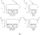
- FIG 1 shows the four topologies of devices 10 with a power electronics converter 12, namely four power electronics enhanced transformers (PEET). Even though PEETs have been used in the following examples, the method, control system and computer program product according to the present invention may be used to control the output voltage of any device in a power grid having an output voltage.
- PEET power electronics enhanced transformers
- a power electronics converter 12 as described herein may comprise any suitable power electronic components such as SCRs, TRIACs, IGBTs, to control and convert electric power.
- the power electronics converter 12 is an AC to AC converter that connects an alternating current source to an alternating current load by controlling amount of power supplied to the load.
- the power electronics converter 12 converts the AC voltage at one level to the other by varying its magnitude as well as frequency of the supply voltage. For AC voltages of the same frequency, the power electronics converter 12 can vary also the phase of the AC voltage.
- Such a power electronics converter 12 may be used in uninterrupted power supplies, high power AC to AC transmission, or renewable energy conversion systems.
- the power electronics enhanced transformer (PEET) used in the method according to the present invention has a much faster response time when it comes to regulating the voltage on the low voltage (LV) side of the transformer 10. This enables the PEET to provide a very rapid demand response when required.
- the output voltage on the LV side of the PEET may be very quickly regulated to achieve a demand response in an active power load.
- a voltage reduction which leads to a load reduction could for example be rapidly applied when the grid frequency in a power grid is reduced below a predetermined reference value, such as a threshold value according to the requirements of a Transmission System Operator for an FFR service.
- the power electronics enhanced transformer (PEET) used in the method according to the present invention will also have a much faster response time when it comes to regulating the voltage on the high voltage (HV) side of a transformer 10 if the power electronics converter 12 is connected to the high voltage (HV) side of the transformer 10.
- the power electronics converters 12 can therefore either be connected to the LV side or the HV side of the transformer 10. From a compactness perspective, it is preferable to connect the power electronics converters 12 to the LV side of the transformer 10.
- control system according to the present invention may be cheaper to implement than a conventional Battery Energy Storage Unit (BESS) since there is no need for energy storage.
- BESS Battery Energy Storage Unit
- FIG. 2 schematically shows a control system 14 for controlling the output voltage of a PEET utilizing local grid frequency determination according to an embodiment of the invention.
- the system 14 comprises an output voltage controller 16, which may be considered to be an FFR controller, and a sensor 18 for measuring a local grid frequency, f meas .
- the local grid frequency, f meas may for example be estimated by a phase-locked loop (PLL) of the power electronics converter 12 of the PEET 10.
- PLL phase-locked loop
- the grid frequency f meas may also be determined a plurality of different places in the power grid and an average value may be determined in order to improve the accuracy of the grid frequency determination.
- the device 10 with a power electronics converter 12 as described herein may be part of a power grid that comprises distributed energy resources (DER), such as distributed renewable energy resources.
- the power grid may supply the demand of a one or more customers and may comprise at least one controllable load.
- the control system 14 is configured to compare the measured grid frequency, f meas , with a reference value for the grid frequency.
- the reference value may for example be the nominal frequency of the power grid, such as 50 Hz.
- the system 14 is configured to produce an error signal corresponding to the difference between the determined grid frequency, f meas , and the reference value, 50 Hz, and apply the error signal as feedback to the output voltage controller 14.
- the control system 14 is configured to generate a control action to cause the output voltage controller 14 to change the output voltage of the PEET 10 to limit the difference between the grid frequency, f meas , and the reference value.
- Primary control may be used to stabilize the grid frequency, f meas
- secondary control may be used to bring the grid frequency f meas , back to the nominal value and restore the power reserve of the generators used for the primary frequency control
- tertiary control may be used to restore the power reserve of the generators used for the secondary frequency control.
- control action as used in this document may therefore be "no action", i.e. the absence of any action to change the output voltage of the device 10.
- the output voltage (with the reference value U ref ) on the low voltage side of the PEET 10 may then be very quickly regulated to achieve a demand response in the active power load.
- Control actions from other controllers may be used bring the grid frequency to the same value as the reference value, or to within a predetermined deviation from the reference value.
- FIG. 3 schematically shows a system 14 for controlling the output voltage of a PEET utilizing a remotely determined grid frequency, f sys , according to another embodiment of the invention.
- the control system 14 comprises a communication channel 20 that is configured to receive a power grid frequency estimation, f sys , from a remote location, such as from a control centre of a Transmission Service Operator, and said control system 14 is configured to determine the power grid frequency of the power grid using that power grid frequency estimation.
- the grid frequency is namely the same throughout the power grid, with the exception of local short-term swings. At every moment the amount of electricity that is generated by the electrical power generating stations of the power grid must be equal to the amount of energy that is taken from the grid by the consumers.
- a control system 14 may comprise both a sensor 18 for utilizing local grid frequency, f meas , and a communication channel 20 for utilizing remote grid frequency, f sys .
- a communication channel 20 may also be used to receive a control action from a remote location, whereby the steps of a control method according to the present invention are carried out at a remote location.
- control system 14 may comprise a single unit, or a plurality of units for carrying out the steps of the method according to the present invention located in one or more locations.
- control system 14 comprise an instrument for continuously determining an active throughput power and the output voltage of the at least one device 10 so as to estimate a voltage dependence of a downstream load in the power grid.
- the amount of active power response (e.g. load reduction) will be dependent on the loading of a device at the point in time of the FFR activation and the voltage dependence of the downstream load.
- the load patterns in a power grid are normally continuously monitored and forecasted. This information may be used together with previous knowledge of the range of the load voltage dependence characteristics and potentially also on-line estimation data of the same, in order to get a good estimate of the available demand response capability unlocked by the device 10.
- a control system 14 may be used to control a plurality of transformers 10 connected in parallel, whereby the control action to change the output voltage of the plurality of transformers 10 is sent to the plurality of transformers at the same time.
- Limitations of a method according to the present invention may exist in cases where a PEET is connected in parallel to one or more regular transformers equipped with OLTCs. In such a case, it may not be suitable to change the output voltage of the PEET quickly as this will result in a difference in the secondary side voltage of the PEET compared with the regular transformers connected in parallel (since OLTCs cannot be controlled as quickly as the PEET). This may cause circulating currents between the transformers which may be unacceptable in some cases. However, in the case where a plurality of PEETs are connected in parallel there should be no such issue since the secondary side voltage of all of the PEETs can be changed at the same time.
- Figure 4 shows the steps of a method for controlling an output voltage of at least one device 10, such as a transformer, in a power grid.
- a computer program product may be used to cause a computer or a processor to execute all of the steps of the method.
- the method provides a decentralized control strategy for power grid components, which utilizes the change in local or remote grid frequency to control the active power consumption within the power grid.
- a device 10 with a power electronics converter 12 that is controlled using a method according to the present invention allows restricted active power flow to a power grid at a desired value.
Landscapes
- Engineering & Computer Science (AREA)
- Power Engineering (AREA)
- Supply And Distribution Of Alternating Current (AREA)
Abstract
A method for controlling an output voltage of at least one device (10), such as a transformer, in a power grid. The method comprises the steps of providing the at least one device (10) with a power electronics converter (12) and an output voltage controller (16), determining a grid frequency of the power grid, comparing the determined grid frequency with a reference value, producing an error signal corresponding to the difference between the determined grid frequency and the reference value, applying the error signal as feedback to the output voltage controller (16), and generating a control action to cause the output voltage controller (16) to change the output voltage of the at least one device (10) comprising a power electronics converter (12) to limit the difference between the grid frequency and the reference value.
Description
- The present invention concerns a method, a computer program product, and a system for controlling an output voltage of at least one device, such as a transformer, in a power grid. The present invention also concerns the use of such a method, computer program product, or system for controlling the active power consumption within a power grid, i.e. any interconnected network for delivering electricity from at least one producer to at least one consumer, such as a transmission and distribution network.
- Power grids consist of electrical power generating stations that are often located near energy resources, electrical substations for stepping electrical voltage up for transmission, or down for distribution, high voltage transmission lines that carry electric power from distant energy sources to demand centres, and distribution lines that supply electrical power to individual customers, such as residential and commercial buildings and industrial parks.
- Centralized power stations, such as coal-fired, gas- or nuclear-powered plants or hydroelectric dams, often require electrical energy to be transmitted over long distances. Electrical energy may however be generated by distributed energy resources (DER) i.e. decentralized and modular technologies, which may be located close to the load that they serve. Due to the increasing integration of renewable energy sources, such as solar power, wind power, biogas, biomass and geothermal power, more power is being injected into alternating current (AC) power grids using power electronic converters. This type of power injection is called non-synchronous generation (NSG), whereby renewable energy sources are non-synchronously connected to the power grid, unlike traditional generation based on large synchronous generators providing the system inertia.
- In some power grids, the penetration of NSG can be very high during certain parts of the year. However high levels of NSG in a power grid bring challenges when it comes to frequency stability, voltage stability, short-circuit power levels and harmonic stability.
- To understand the frequency control issue in power grids with a high penetration of NSG it is instructive to review synchronous machine dynamics. A synchronous power grid may, through a crude approximation, be seen as a single synchronous machine with a turbine, where mechanical power is being generated, and which is connected to an electrical load. The electro-mechanical equation of a single synchronous machine (SM) can be written as:

where J is the moment of inertia [kg*m2], ωm is the rotational speed of the machine [rad/s], Pm is the mechanical power supplied from the turbine [W], and Pe is the output electrical power [W]. - In an electrical power grid, the grid frequency needs to be constantly controlled by adjusting the generation (Pm ) with respect to the instantaneous load (Pe ) in the grid. If the mechanical power supplied from the turbine is greater than the output electrical power (Pm>Pe ), the grid frequency will increase. If the mechanical power supplied from the turbine is less than the output electrical power (Pm<Pe ), the grid frequency will decrease. The grid frequency is usually maintained within a narrow frequency band around the nominal grid frequency (which is 50 Hz in European power grids, and 60 Hz in the US) by automatically controlling power generation.
- In power grids with a high penetration of NSG, synchronous generation is disconnected from the grid and the rotating inertia in the grid thereby decreases. This means that the effective moment of inertia, J, in the equation given above is reduced. This in turn leads to a faster change in the frequency if a mismatch between generated and consumed power occurs (for example due to a trip event of one large generator in the grid). In order to keep a grid frequency within the same range for a grid with low inertia, a faster regulation of the active power balance is required.
- In order to address the challenge of frequency control, which is related to the low amount of rotating inertia in NSG-rich grids, Transmission System Operators are using several mitigation methods. One such mitigation method utilizes fast frequency control units, which are capable of responding very quickly when the grid frequency deviates outside a dead-band, i.e. a band of input values in a control system where the output is zero (the output is 'dead' - no action occurs). Examples of units which may provide fast frequency response (FFR) are Battery Energy Storage Units (BESS) and HVDC links.
- Another mitigation method that can be used to control the frequency in a power grid is Demand Response, which is defined by the Federal Energy Regulatory Commission (FERC) in the US as: "Changes in electric usage by end-use customers from their normal consumption patterns in response to changes in the price of electricity over time, or to incentive payments designed to induce lower electricity use at times of high wholesale market prices or when system reliability is jeopardized." Controlled load shedding is widely adopted as a last alternative to save a power grid from a black-out after severe and un-anticipated faults in the power grid.
- Rapid control of the load in a power grid, i.e. Fast Demand Response, is an alternative to providing Fast Frequency Response to improve the frequency containment in grids with increasing levels of NSG and reduced levels of rotating inertia. For example, the PhD thesis by Yue Guo entitled "Capability Assessment of VAr Support and Demand Response to Transmission Network using Flexible Tap Changing Techniques in Distribution Networks", which was published in 2017 and which is available from the University of Manchester Library, discusses the flexible tap changing techniques that utilise parallel transformers in distribution networks to provide reactive power absorption and demand response services for transmission systems.
- The author of this PhD thesis found that a demand reduction could be achieved without violating the voltage limits in the distribution grid, and voltage reductions in the range of 1-4 % were recommended. The effect on the loads is directly related to the voltage dependence of the loads in the distribution grid. Different load characteristics were investigated as part of this PhD work and the active power demand change resulting from the voltage reduction applied was found to be roughly between 0 (for constant active power load) and 5% (for constant impedance load). In many cases, a load reduction of a couple of per cent could be achieved without violating the voltage constraints in the distribution grid in the study.
- Additionally, the article by A. Ballanti and L. F. Ochoa, entitled "Initial assessment of voltage-led demand response from UK residential loads," which was published in IEEE Power & Energy Society Innovative Smart Grid Technologies Conference (ISGT), 2015, pp. 1-5 presents and applies two load modelling methodologies, time independent and time varying, to a single primary substation and then extends the methodologies to the entire distribution network operator area. The results for the time-varying model, a purely residential load, and a 3% voltage reduction during a winter day showed that it could be possible to achieve an aggregated peak reduction exceeding 150 MW i.e. more than 3%.
- These prior art documents show that some level of slow control of the load in a distribution grid can be achieved by controlling the On-Load Tap Changer (OLTC) of distribution transformers to regulate the voltage without violating the voltage control requirements of the power grid. However, given the slow time response of an OLTC, a standard distribution transformer with an OLTC cannot provide a rapid demand response and thus participate in the fast frequency control action of a power grid which is increasingly desired in today's power grids.
- An object of the invention is to provide an improved method for controlling an output voltage of at least one device, such as a transformer, Thyristor Controlled Reactor (TCR), Static Var Compensator (SVC), or Static Synchronous Compensator (STATCOM), in a power grid.
- This object is achieved by a method comprising the method steps recited in claim 1. The method comprises the steps of providing the at least one device with a power electronics converter and an output voltage controller, determining (i.e. measuring, estimating, calculating or receiving) a grid frequency of the power grid, comparing the determined grid frequency with a reference value, producing an error signal corresponding to the difference between the determined grid frequency and the reference value, applying the error signal as feedback to the output voltage controller, and generating a control action to cause the output voltage controller to change the output voltage of the at least one device comprising a power electronics converter to limit the difference between the grid frequency and the reference value, i.e. to limit the maximum frequency deviation.
- This method may for example control the output voltage of a power electronics enhanced transformer (PEET), using a measurement of the grid frequency such that the output voltage of the PEET is a function of the grid frequency. When the grid frequency falls below a predetermined reference value, or lies outside a predetermined range of predetermined frequency values, such as a a pre-defined dead-band, the output voltage of the at least one device may be lowered, and when the grid frequency rises above a predetermined reference value or a predetermined range of grid frequency values, the output voltage of the at least one device may be increased.
- The objective of the control method according to the present invention is namely to develop a model or algorithm governing the application of power grid system-inputs to drive the system to a desired state, while minimizing any delay, overshoot, or steady state error and ensuring a level of control stability, with the aim of achieving a degree of optimality. To do this, a control method or control system with the requisite corrective behaviour is required. The control method and control system according to the present invention use feedback control to monitor a process variable, i.e. the grid frequency, by taking measurements of the grid frequency using a sensor or by receiving a grid frequency estimate from a remote location for example. A local controller may be used to estimate the relationship between the output voltage of a device in the power grid and the active power drawn by a load downstream of the device in order to know the demand response active power variation that can be achieved by a voltage change in advance.
- According to an embodiment of the invention the step of determining the grid frequency of the power grid comprises the step of estimating a local power grid frequency using a phase-locked loop (PLL) of the power electronics converter.
- Alternatively, the step of determining the power grid frequency of the power grid comprises the step of the output voltage controller receiving a power grid frequency estimation from a remote location, such as from a control centre of a Transmission Service Operator, via a communication channel. The power grid frequency estimation is namely received from a remote location rather than being measured locally.
- According to an embodiment of the invention at least one method step or the entire method may be carried out at a remote location whereby the control action is sent to the output voltage controller via a communication channel. A single control system may namely be used to control the output voltage of a plurality of devices located in different places in a power grid.
- According to an embodiment of the invention the method comprises the step of continuously determining an active throughput power and the output voltage of the at least one device so as to estimate a voltage dependence of a downstream load in the power grid.
- According to an embodiment of the invention the method comprises the step of controlling a plurality of transformers connected in parallel, whereby the control action to change the output voltage of the plurality of transformers is sent to the plurality of transformers at the same time. Depending on the communication between the output voltage controller and the local power electronics converters of the plurality of transformers, the method may comprise the step of sending a synchronization signal to synchronize the clocks of the local output voltage controllers of the power electronics converters of the plurality of transformers.
- According to an embodiment of the invention the step of determining the grid frequency comprises the step of determining a grid frequency at a plurality of different places in the power grid in order to increase the accuracy of the grid frequency determination.
- The present invention also concerns a computer program product that comprises a computer program containing computer program code means arranged to cause a computer or a processor to execute all of the steps of a method according to any of the embodiments of the invention, stored on a computer-readable medium or a carrier wave.
- The present invention further concerns a control system for controlling an output voltage of at least one device, such as a transformer transformer, Thyristor Controlled Reactor (TCR), Static Var Compensator (SVC) or Static Synchronous Compensator (STATCOM), in a power grid. The at least one device comprises a power electronics converter and the control system comprises an output voltage controller and a sensor configured to determine a grid frequency of the power grid, i.e. the sensor is configured to measure, estimate, or receive the grid frequency of the power grid. The control system is configured to compare the determined grid frequency with a reference value, produce an error signal corresponding to the difference between the determined grid frequency and the reference value and apply the error signal as feedback to the output voltage controller, and cause the output voltage controller to generate a control action to change the output voltage of the at least one device comprising a power electronics converter to limit the difference between the grid frequency and the reference value.
- The reference value may be a nominal grid frequency or a value indicating a maximum or minimum allowed grid frequency, such as an upper or lower limit of a dead-band frequency range.
- According to an embodiment of the invention the power electronics converter comprises a phase-locked loop (PLL) configured to determine the grid frequency of the power grid by estimating a local power grid frequency
- According to an embodiment of the invention the control system comprises a communication channel configured to receive a power grid frequency estimation from a remote location, such as from a control centre of a Transmission Service Operator, and the control system is configured to determine the power grid frequency of the power grid using the power grid frequency estimation.
- According to an embodiment of the invention the control system comprises a communication channel that is configured to receive the generated control action from a remote location, such as from a control centre of a Transmission Service Operator.
- According to an embodiment of the invention the control system comprises an instrument that is configured to continuously measure an active throughput power and the output voltage of the at least one device, and the control system is configured to estimate a voltage dependence of a downstream load in the power grid using the measurements.
- According to an embodiment of the invention the control system is configured to control the output voltage of a plurality of transformers that are connected in parallel and that comprise a power electronics converter, and the output voltage controller is configured to send the control action to change the output voltage of the plurality of transformers to the plurality of transformers at the same time. Depending on the communication between the output voltage controller and the local power electronics converters of the plurality of transformers, the control system may be configured to send a synchronization signal to synchronize the clocks of the local output voltage controllers of the power electronics converters of the plurality of transformers.
- The present invention also concerns the use of a method, or a computer program product or a control system according to any of the embodiments described herein for controlling the active power consumption within a power grid.
- The present invention will hereinafter be further explained by means of non-limiting examples with reference to the appended figures where;
- Figure 1
- shows four topologies of PEET devices,
- Figure 2
- schematically shows a system for controlling the output voltage of a PEET utilizing local grid frequency determination according to an embodiment of the invention,
- Figure 3
- schematically shows a system for controlling the output voltage of a PEET utilizing remote grid frequency determination according to another embodiment of the invention, and
- ,Figure 4
- is a flow diagram showing the steps of a method according to an embodiment of the present invention.
- It should be noted that the drawings have not necessarily been drawn to scale and that the dimensions of certain features may have been exaggerated for the sake of clarity.
-
Figure 1 shows the four topologies ofdevices 10 with apower electronics converter 12, namely four power electronics enhanced transformers (PEET). Even though PEETs have been used in the following examples, the method, control system and computer program product according to the present invention may be used to control the output voltage of any device in a power grid having an output voltage. - A
power electronics converter 12 as described herein may comprise any suitable power electronic components such as SCRs, TRIACs, IGBTs, to control and convert electric power. According to an embodiment of the invention thepower electronics converter 12 is an AC to AC converter that connects an alternating current source to an alternating current load by controlling amount of power supplied to the load. Thepower electronics converter 12 converts the AC voltage at one level to the other by varying its magnitude as well as frequency of the supply voltage. For AC voltages of the same frequency, thepower electronics converter 12 can vary also the phase of the AC voltage. - Such a
power electronics converter 12 may be used in uninterrupted power supplies, high power AC to AC transmission, or renewable energy conversion systems. - By replacing an on-load tap changer (OLTC) of a transformer with a
power electronics converter 12 to regulate the voltage on the secondary side of thetransformer 10, the inventors have found that it is possible to control the output voltage of thetransformer 10 much faster than with an OLTC solution. - Compared to a transformer with an OLTC, the power electronics enhanced transformer (PEET) used in the method according to the present invention has a much faster response time when it comes to regulating the voltage on the low voltage (LV) side of the
transformer 10. This enables the PEET to provide a very rapid demand response when required. The output voltage on the LV side of the PEET may be very quickly regulated to achieve a demand response in an active power load. A voltage reduction which leads to a load reduction could for example be rapidly applied when the grid frequency in a power grid is reduced below a predetermined reference value, such as a threshold value according to the requirements of a Transmission System Operator for an FFR service. - It should be noted that the power electronics enhanced transformer (PEET) used in the method according to the present invention will also have a much faster response time when it comes to regulating the voltage on the high voltage (HV) side of a
transformer 10 if thepower electronics converter 12 is connected to the high voltage (HV) side of thetransformer 10. In all of the topologies shown inFigure 1 , thepower electronics converters 12 can therefore either be connected to the LV side or the HV side of thetransformer 10. From a compactness perspective, it is preferable to connect thepower electronics converters 12 to the LV side of thetransformer 10. - Furthermore, the control system according to the present invention may be cheaper to implement than a conventional Battery Energy Storage Unit (BESS) since there is no need for energy storage.
-
Figure 2 schematically shows acontrol system 14 for controlling the output voltage of a PEET utilizing local grid frequency determination according to an embodiment of the invention. Thesystem 14 comprises anoutput voltage controller 16, which may be considered to be an FFR controller, and asensor 18 for measuring a local grid frequency, fmeas, The local grid frequency, fmeas, may for example be estimated by a phase-locked loop (PLL) of thepower electronics converter 12 of thePEET 10. The grid frequency fmeas, may also be determined a plurality of different places in the power grid and an average value may be determined in order to improve the accuracy of the grid frequency determination. - The
device 10 with apower electronics converter 12 as described herein may be part of a power grid that comprises distributed energy resources (DER), such as distributed renewable energy resources. The power grid may supply the demand of a one or more customers and may comprise at least one controllable load. - The
control system 14 is configured to compare the measured grid frequency, fmeas, with a reference value for the grid frequency. The reference value may for example be the nominal frequency of the power grid, such as 50 Hz. Thesystem 14 is configured to produce an error signal corresponding to the difference between the determined grid frequency, fmeas, and the reference value, 50 Hz, and apply the error signal as feedback to theoutput voltage controller 14. If the grid frequency, fmeas, lies outside a predefined dead-band, such as below 49.9 Hz or above 50.1 Hz indicating that an event, such as a trip event of a large generator in the power grid may have occurred, thecontrol system 14 is configured to generate a control action to cause theoutput voltage controller 14 to change the output voltage of thePEET 10 to limit the difference between the grid frequency, fmeas, and the reference value. Primary control may be used to stabilize the grid frequency, fmeas, secondary control may be used to bring the grid frequency fmeas, back to the nominal value and restore the power reserve of the generators used for the primary frequency control, and tertiary control may be used to restore the power reserve of the generators used for the secondary frequency control. - If the measured grid frequency, fmeas, lies within the range 49.9 Hz to 50.1 Hz, no control action will be generated. A "control action" as used in this document may therefore be "no action", i.e. the absence of any action to change the output voltage of the
device 10. - If a control action to change the output of the
device 10 is necessary, the output voltage (with the reference value Uref ) on the low voltage side of thePEET 10 may then be very quickly regulated to achieve a demand response in the active power load. - Control actions from other controllers, such as the frequency governors of generators and possibly other demand response schemes, may be used bring the grid frequency to the same value as the reference value, or to within a predetermined deviation from the reference value.
-
Figure 3 schematically shows asystem 14 for controlling the output voltage of a PEET utilizing a remotely determined grid frequency, fsys , according to another embodiment of the invention. Thecontrol system 14 comprises acommunication channel 20 that is configured to receive a power grid frequency estimation, fsys , from a remote location, such as from a control centre of a Transmission Service Operator, and saidcontrol system 14 is configured to determine the power grid frequency of the power grid using that power grid frequency estimation. The grid frequency is namely the same throughout the power grid, with the exception of local short-term swings. At every moment the amount of electricity that is generated by the electrical power generating stations of the power grid must be equal to the amount of energy that is taken from the grid by the consumers. - A
control system 14 according to the present invention may comprise both asensor 18 for utilizing local grid frequency, fmeas, and acommunication channel 20 for utilizing remote grid frequency, fsys . - A
communication channel 20 may also be used to receive a control action from a remote location, whereby the steps of a control method according to the present invention are carried out at a remote location. - It should be noted that the components of a
control system 14 according to the present invention need not necessarily be located at the same location. Thecontrol system 14 may comprise a single unit, or a plurality of units for carrying out the steps of the method according to the present invention located in one or more locations. - It will be important to have an estimate of the voltage dependence of the loads in the power grid in which the
device 10device 10 with apower electronics converter 12 is connected in order to know how much demand response is available at any given time. According to an embodiment of the invention thecontrol system 14 comprise an instrument for continuously determining an active throughput power and the output voltage of the at least onedevice 10 so as to estimate a voltage dependence of a downstream load in the power grid. The aim of such a method step may for example be to determine the exponent np in the equation below based on measurements of the output voltage of thedevice 10 and the throughput power P of thedevice 10,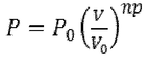
- An uncertainty will always exist in the forecasted assessment of the available demand response capability accessible by the methods according to the present invention. The amount of active power response (e.g. load reduction) will be dependent on the loading of a device at the point in time of the FFR activation and the voltage dependence of the downstream load. The load patterns in a power grid are normally continuously monitored and forecasted. This information may be used together with previous knowledge of the range of the load voltage dependence characteristics and potentially also on-line estimation data of the same, in order to get a good estimate of the available demand response capability unlocked by the
device 10. - According to an embodiment of the invention a
control system 14 according to the present invention may be used to control a plurality oftransformers 10 connected in parallel, whereby the control action to change the output voltage of the plurality oftransformers 10 is sent to the plurality of transformers at the same time. - Limitations of a method according to the present invention may exist in cases where a PEET is connected in parallel to one or more regular transformers equipped with OLTCs. In such a case, it may not be suitable to change the output voltage of the PEET quickly as this will result in a difference in the secondary side voltage of the PEET compared with the regular transformers connected in parallel (since OLTCs cannot be controlled as quickly as the PEET). This may cause circulating currents between the transformers which may be unacceptable in some cases. However, in the case where a plurality of PEETs are connected in parallel there should be no such issue since the secondary side voltage of all of the PEETs can be changed at the same time.
-
Figure 4 shows the steps of a method for controlling an output voltage of at least onedevice 10, such as a transformer, in a power grid. A computer program product may be used to cause a computer or a processor to execute all of the steps of the method. The method provides a decentralized control strategy for power grid components, which utilizes the change in local or remote grid frequency to control the active power consumption within the power grid. Adevice 10 with apower electronics converter 12 that is controlled using a method according to the present invention allows restricted active power flow to a power grid at a desired value. - Further modifications of the invention within the scope of the claims would be apparent to a skilled person.
Claims (15)
- A method for controlling an output voltage of at least one device (10), such as a transformer, in a power grid, characterized in that said method comprises the steps of providing said at least one device (10) with a power electronics converter (12) and an output voltage controller (16), determining a grid frequency of said power grid, comparing said determined grid frequency with a reference value, producing an error signal corresponding to the difference between said determined grid frequency and said reference value, applying said error signal as feedback to said output voltage controller (16), and generating a control action to cause said output voltage controller (16) to change the output voltage of said at least one device (10) comprising a power electronics converter (12) to limit the difference between the grid frequency and the reference value.
- A method according to claim 1, characterized in that said step of determining said grid frequency of said power grid comprises the step of estimating a local power grid frequency (fmeas ) using a phase-locked loop (PLL) of said power electronics converter (12).
- A method according to claim 1, characterized in that said step of determining said power grid frequency of said power grid comprises the step of said output voltage controller (16) receiving a power grid frequency estimation (fsys ) from a remote location, such as from a control centre of a Transmission Service Operator, via a communication channel (20).
- A method according to claim 1, characterized in that it is carried out at a remote location and said control action is sent to said output voltage controller (16) via a communication channel (20).
- A method according to any of the preceding claims, characterized in that it comprises the step of continuously determining an active throughput power and said output voltage of said at least one device (10) so as to estimate a voltage dependence of a downstream load in said power grid.
- A method according to any of the preceding claims, characterized in that it comprises the step of controlling a plurality of transformers connected in parallel, whereby said control action to change the output voltage of said plurality of transformers is sent to said plurality of transformers at the same time, and optionally said method comprises the step of sending a synchronization signal to synchronize clocks of local output voltage controllers (16) of power electronics converters (12) of said plurality of transformers.
- A method according to any of the preceding claims, characterized in that said step of determining said grid frequency (fmeas, fsys ) comprises the step of determining a grid frequency at a plurality of different places in said power grid.
- A computer program product characterized in that it comprises a computer program containing computer program code means arranged to cause a computer or a processor to execute all of the steps of a method according to any of claims 1-7, stored on a computer-readable medium or a carrier wave.
- A control system for controlling an output voltage of at least one device (10), such as a transformer, in a power grid, characterized in that said whereby said at least one device (10) comprises a power electronics converter (12) and said control system comprises an output voltage controller (16) and a sensor (18) configured to determine a grid frequency of said power grid, and whereby said control system is configured to compare said determined grid frequency with a reference value, produce an error signal corresponding to the difference between said determined grid frequency and said reference value and apply said error signal as feedback to said output voltage controller (16), and cause said output voltage controller (16) to generate a control action to change the output voltage of said at least one device (10) comprising a power electronics converter (12) to limit the difference between the grid frequency and the reference value.
- A control system according to claim 9, characterized in that said power electronics converter (12) comprises a phase-locked loop (PLL) configured to determine said grid frequency of said power grid by estimating a local power grid frequency (fmeas ).
- A control system according to claim 9, characterized in that it comprises a communication channel (20) configured to receive a power grid frequency estimation (fsus ) from a remote location, such as from a control centre of a Transmission Service Operator, and said control system is configured to determine said power grid frequency of said power grid using said power grid frequency estimation (fsus ).
- A control system according to any of claims 9-11, characterized in that it comprises a communication channel (20) that is configured to receive said generated control action from a remote location, such as from a control centre of a Transmission Service Operator.
- A control system according to any of claims 9-12, characterized in that it comprises an instrument that is configured to continuously measure an active throughput power and said output voltage of said at least one device (10), and said control system is configured to estimate a voltage dependence of a downstream load in said power grid using said measurements.
- A control system according to any of claims 9-13, characterized in that it is configured to control the output voltage of a plurality of transformers that are connected in parallel and that comprise a power electronics converter (12), and said output voltage controller (16) is configured to send said control action to change the output voltage of said plurality of transformers to said plurality of transformers at the same time, and optionally said control system is configured to send a synchronization signal to synchronize clocks of local output voltage controllers (16) of power electronics converters (12) of said plurality of transformers.
- Use of a method according to any of claims 1-7, or a computer program product according to claim 8, or a control system according to any of claims 9-14, for controlling the active power consumption within a power grid.
Priority Applications (8)
| Application Number | Priority Date | Filing Date | Title |
|---|---|---|---|
| EP21162435.8A EP4057468A1 (en) | 2021-03-12 | 2021-03-12 | Control method, computer program product, control system & use |
| KR1020237030466A KR102618098B1 (en) | 2021-03-12 | 2022-02-24 | Control methods, computer program products, control systems and uses |
| EP22712527.5A EP4298705B1 (en) | 2021-03-12 | 2022-02-24 | Control method, computer program product, control system & use |
| JP2023554823A JP7545591B2 (en) | 2021-03-12 | 2022-02-24 | CONTROL METHOD, COMPUTER PROGRAM PRODUCT, CONTROL SYSTEM, AND USE |
| PL22712527.5T PL4298705T3 (en) | 2021-03-12 | 2022-02-24 | Control method, computer program product, control system & use |
| PCT/EP2022/054652 WO2022189160A1 (en) | 2021-03-12 | 2022-02-24 | Control method, computer program product, control system & use |
| CN202280019541.1A CN116982232B (en) | 2021-03-12 | 2022-02-24 | Control method, computer program product, control system and use |
| US18/281,362 US12081020B2 (en) | 2021-03-12 | 2022-02-24 | Control method, computer program product, control system and use |
Applications Claiming Priority (1)
| Application Number | Priority Date | Filing Date | Title |
|---|---|---|---|
| EP21162435.8A EP4057468A1 (en) | 2021-03-12 | 2021-03-12 | Control method, computer program product, control system & use |
Publications (1)
| Publication Number | Publication Date |
|---|---|
| EP4057468A1 true EP4057468A1 (en) | 2022-09-14 |
Family
ID=74873663
Family Applications (2)
| Application Number | Title | Priority Date | Filing Date |
|---|---|---|---|
| EP21162435.8A Withdrawn EP4057468A1 (en) | 2021-03-12 | 2021-03-12 | Control method, computer program product, control system & use |
| EP22712527.5A Active EP4298705B1 (en) | 2021-03-12 | 2022-02-24 | Control method, computer program product, control system & use |
Family Applications After (1)
| Application Number | Title | Priority Date | Filing Date |
|---|---|---|---|
| EP22712527.5A Active EP4298705B1 (en) | 2021-03-12 | 2022-02-24 | Control method, computer program product, control system & use |
Country Status (7)
| Country | Link |
|---|---|
| US (1) | US12081020B2 (en) |
| EP (2) | EP4057468A1 (en) |
| JP (1) | JP7545591B2 (en) |
| KR (1) | KR102618098B1 (en) |
| CN (1) | CN116982232B (en) |
| PL (1) | PL4298705T3 (en) |
| WO (1) | WO2022189160A1 (en) |
Families Citing this family (1)
| Publication number | Priority date | Publication date | Assignee | Title |
|---|---|---|---|---|
| CN118137859B (en) * | 2024-05-08 | 2024-08-09 | 东北电力大学 | Direct type AC/AC-HV type hybrid distribution transformer |
Family Cites Families (11)
| Publication number | Priority date | Publication date | Assignee | Title |
|---|---|---|---|---|
| JPS6277023A (en) * | 1985-09-30 | 1987-04-09 | 株式会社東芝 | Voltage controller |
| US6670721B2 (en) * | 2001-07-10 | 2003-12-30 | Abb Ab | System, method, rotating machine and computer program product for enhancing electric power produced by renewable facilities |
| JP3651796B2 (en) | 2002-08-05 | 2005-05-25 | 株式会社東芝 | Power converter |
| US7571028B2 (en) | 2005-04-19 | 2009-08-04 | Genscape Intangible Holding, Inc. | Method and system for AC power grid monitoring |
| ATE529939T1 (en) * | 2008-10-27 | 2011-11-15 | Abb Research Ltd | CONVERTER CIRCUIT AND UNIT AND SYSTEM HAVING SUCH A CONVERTER CIRCUIT |
| PL2394356T3 (en) * | 2009-02-06 | 2019-01-31 | Abb Research Ltd. | A hybrid distribution transformer with ac&dc power capabilities |
| CA2812627C (en) * | 2010-09-28 | 2019-10-29 | Siemens Aktiengesellschaft | Power oscillation damping by a converter-based power generation device |
| CN106026686A (en) * | 2016-05-25 | 2016-10-12 | 中国电力科学研究院 | Power electronic transformer integrated with energy storage system |
| WO2018049473A1 (en) * | 2016-09-14 | 2018-03-22 | Faraday Grid Limited | An electrical power distribution network and process |
| DE102016119422A1 (en) * | 2016-10-12 | 2018-04-12 | Christian-Albrechts-Universität Zu Kiel | Method for operating an electrical power supply network, computer program, power electronic device and power supply network |
| US10422846B2 (en) * | 2017-01-30 | 2019-09-24 | Rohde & Schwarz Gmbh & Co. Kg | Method for calibrating a radio frequency test instrument and radio frequency test instrument |
-
2021
- 2021-03-12 EP EP21162435.8A patent/EP4057468A1/en not_active Withdrawn
-
2022
- 2022-02-24 US US18/281,362 patent/US12081020B2/en active Active
- 2022-02-24 KR KR1020237030466A patent/KR102618098B1/en active Active
- 2022-02-24 WO PCT/EP2022/054652 patent/WO2022189160A1/en not_active Ceased
- 2022-02-24 CN CN202280019541.1A patent/CN116982232B/en active Active
- 2022-02-24 JP JP2023554823A patent/JP7545591B2/en active Active
- 2022-02-24 EP EP22712527.5A patent/EP4298705B1/en active Active
- 2022-02-24 PL PL22712527.5T patent/PL4298705T3/en unknown
Non-Patent Citations (6)
| Title |
|---|
| A. BALLANTIL. F. OCHOA: "Initial assessment of voltage-led demand response from UK residential loads", IEEE POWER & ENERGY SOCIETY INNOVATIVE SMART GRID TECHNOLOGIES CONFERENCE (ISGT), 2015, pages 1 - 5, XP032787903, DOI: 10.1109/ISGT.2015.7131821 |
| BAIER CARLOS R ET AL: "Hybrid Transformers with Virtual Inertia for Future Distribution Networks", IECON 2019 - 45TH ANNUAL CONFERENCE OF THE IEEE INDUSTRIAL ELECTRONICS SOCIETY, IEEE, vol. 1, 14 October 2019 (2019-10-14), pages 6767 - 6772, XP033669752, DOI: 10.1109/IECON.2019.8926954 * |
| LANGWASSER MARIUS ET AL: "Smart Transformer-based Frequency Support in Variable Inertia Conditions", 2019 IEEE 13TH INTERNATIONAL CONFERENCE ON COMPATIBILITY, POWER ELECTRONICS AND POWER ENGINEERING (CPE-POWERENG), IEEE, 23 April 2019 (2019-04-23), pages 1 - 6, XP033627861, DOI: 10.1109/CPE.2019.8862365 * |
| MURAD MOHAMMED AHSAN ADIB ET AL: "Frequency Control Through Voltage Regulation of Power System Using SVC Devices", 2019 IEEE POWER & ENERGY SOCIETY GENERAL MEETING (PESGM), IEEE, 4 August 2019 (2019-08-04), pages 1 - 5, XP033699730, DOI: 10.1109/PESGM40551.2019.8973807 * |
| TU YUXIAOYING ET AL: "Smart Transformer Modelling and Hardware in-the-loop Validation", 2019 IEEE 10TH INTERNATIONAL SYMPOSIUM ON POWER ELECTRONICS FOR DISTRIBUTED GENERATION SYSTEMS (PEDG), IEEE, 3 June 2019 (2019-06-03), pages 1019 - 1025, XP033601791, DOI: 10.1109/PEDG.2019.8807484 * |
| YUE GUO: "PhD thesis", 2017, UNIVERSITY OF MANCHESTER LIBRARY, article "Capability Assessment of VAr Support and Demand Response to Transmission Network using Flexible Tap Changing Techniques in Distribution Networks" |
Also Published As
| Publication number | Publication date |
|---|---|
| CN116982232A (en) | 2023-10-31 |
| JP2024508036A (en) | 2024-02-21 |
| EP4298705B1 (en) | 2024-07-17 |
| PL4298705T3 (en) | 2024-11-18 |
| KR20230132890A (en) | 2023-09-18 |
| JP7545591B2 (en) | 2024-09-04 |
| WO2022189160A1 (en) | 2022-09-15 |
| US12081020B2 (en) | 2024-09-03 |
| CN116982232B (en) | 2025-01-21 |
| EP4298705A1 (en) | 2024-01-03 |
| US20240097442A1 (en) | 2024-03-21 |
| KR102618098B1 (en) | 2023-12-27 |
Similar Documents
| Publication | Publication Date | Title |
|---|---|---|
| Kashani et al. | Smart inverter volt-watt control design in high PV-penetrated distribution systems | |
| EP3367547B1 (en) | Intra-area master reactive controller for tightly coupled windfarms | |
| EP2602898B1 (en) | System and method for reactive power compensation in power networks | |
| Hossain et al. | Active power management in a low-voltage islanded microgrid | |
| Robitzky et al. | Impact of active distribution networks on voltage stability of electric power systems | |
| Song et al. | Coordinated adaptive droop control of large-scale energy storage systems for primary frequency support in energy management systems | |
| EP4298705B1 (en) | Control method, computer program product, control system & use | |
| Halley et al. | Renewable Energy on the Apple Isle: Managing a high penetration of inverter-based energy resources in Tasmania | |
| Von Meier | Integration of renewable generation in California: Coordination challenges in time and space | |
| Parol et al. | Voltage stability in low voltage microgrids in aspects of active and reactive power demand | |
| WO2024254063A1 (en) | Coordination and control of controllable energy resources in an electric network to maintain continuous supply and demand balance | |
| EP3526873B1 (en) | Method for operating an electrical power supply grid, computer program, power electronics device and power supply grid | |
| Abdelwahed | Multi-terminal vsc-hvdc based offshore wind-farms integration system operation and control | |
| US20220385070A1 (en) | Method for controlling voltage and reactive power for an electrical grid | |
| Nanou et al. | Evaluation of DC voltage control strategies for multi-terminal HVDC grids comprising island systems with high RES penetration | |
| Goikoetxea et al. | Active substation design to maximize DG integration | |
| Roscoe et al. | Increasing security of supply by the use of a local power controller during large system disturbances | |
| Papadimitriou et al. | Assessing renewables uncertainties in the short-term (day-ahead) scheduling of DER | |
| Elkholy et al. | Islanding Scenarios for High Reliable Operation of Distribution Networks | |
| Wu et al. | A reactive power sharing strategy of parallel inverters based on parameter perturbation | |
| JP2025160550A (en) | Power system operation planning device, power system operation planning system, and power system operation planning method | |
| Zhou et al. | Autonomous control integrating fast voltage regulation and islanding detection for high penetration PV application | |
| Li et al. | Power Control Assessment Technology | |
| Fan et al. | Distributed resources for power system frequency regulation: a review | |
| Maucher et al. | Superordinate control for increasing feed-in capacity and improving power quality in low voltage distribution grids |
Legal Events
| Date | Code | Title | Description |
|---|---|---|---|
| PUAI | Public reference made under article 153(3) epc to a published international application that has entered the european phase |
Free format text: ORIGINAL CODE: 0009012 |
|
| STAA | Information on the status of an ep patent application or granted ep patent |
Free format text: STATUS: THE APPLICATION HAS BEEN PUBLISHED |
|
| AK | Designated contracting states |
Kind code of ref document: A1 Designated state(s): AL AT BE BG CH CY CZ DE DK EE ES FI FR GB GR HR HU IE IS IT LI LT LU LV MC MK MT NL NO PL PT RO RS SE SI SK SM TR |
|
| STAA | Information on the status of an ep patent application or granted ep patent |
Free format text: STATUS: THE APPLICATION HAS BEEN WITHDRAWN |
|
| 18W | Application withdrawn |
Effective date: 20220930 |