EP4057401A1 - Fuel battery cell and method for manufacturing fuel battery cell - Google Patents
Fuel battery cell and method for manufacturing fuel battery cell Download PDFInfo
- Publication number
- EP4057401A1 EP4057401A1 EP19951820.0A EP19951820A EP4057401A1 EP 4057401 A1 EP4057401 A1 EP 4057401A1 EP 19951820 A EP19951820 A EP 19951820A EP 4057401 A1 EP4057401 A1 EP 4057401A1
- Authority
- EP
- European Patent Office
- Prior art keywords
- opening
- insulating film
- battery cell
- electrode
- fuel battery
- Prior art date
- Legal status (The legal status is an assumption and is not a legal conclusion. Google has not performed a legal analysis and makes no representation as to the accuracy of the status listed.)
- Withdrawn
Links
Images





Classifications
-
- H—ELECTRICITY
- H01—ELECTRIC ELEMENTS
- H01M—PROCESSES OR MEANS, e.g. BATTERIES, FOR THE DIRECT CONVERSION OF CHEMICAL ENERGY INTO ELECTRICAL ENERGY
- H01M8/00—Fuel cells; Manufacture thereof
- H01M8/10—Fuel cells with solid electrolytes
- H01M8/12—Fuel cells with solid electrolytes operating at high temperature, e.g. with stabilised ZrO2 electrolyte
- H01M8/1213—Fuel cells with solid electrolytes operating at high temperature, e.g. with stabilised ZrO2 electrolyte characterised by the electrode/electrolyte combination or the supporting material
- H01M8/1226—Fuel cells with solid electrolytes operating at high temperature, e.g. with stabilised ZrO2 electrolyte characterised by the electrode/electrolyte combination or the supporting material characterised by the supporting layer
-
- H—ELECTRICITY
- H01—ELECTRIC ELEMENTS
- H01M—PROCESSES OR MEANS, e.g. BATTERIES, FOR THE DIRECT CONVERSION OF CHEMICAL ENERGY INTO ELECTRICAL ENERGY
- H01M8/00—Fuel cells; Manufacture thereof
- H01M8/10—Fuel cells with solid electrolytes
- H01M8/1097—Fuel cells applied on a support, e.g. miniature fuel cells deposited on silica supports
-
- H—ELECTRICITY
- H01—ELECTRIC ELEMENTS
- H01M—PROCESSES OR MEANS, e.g. BATTERIES, FOR THE DIRECT CONVERSION OF CHEMICAL ENERGY INTO ELECTRICAL ENERGY
- H01M8/00—Fuel cells; Manufacture thereof
- H01M8/10—Fuel cells with solid electrolytes
- H01M8/12—Fuel cells with solid electrolytes operating at high temperature, e.g. with stabilised ZrO2 electrolyte
- H01M8/1213—Fuel cells with solid electrolytes operating at high temperature, e.g. with stabilised ZrO2 electrolyte characterised by the electrode/electrolyte combination or the supporting material
-
- H—ELECTRICITY
- H01—ELECTRIC ELEMENTS
- H01M—PROCESSES OR MEANS, e.g. BATTERIES, FOR THE DIRECT CONVERSION OF CHEMICAL ENERGY INTO ELECTRICAL ENERGY
- H01M8/00—Fuel cells; Manufacture thereof
- H01M8/10—Fuel cells with solid electrolytes
- H01M8/12—Fuel cells with solid electrolytes operating at high temperature, e.g. with stabilised ZrO2 electrolyte
- H01M8/1231—Fuel cells with solid electrolytes operating at high temperature, e.g. with stabilised ZrO2 electrolyte with both reactants being gaseous or vaporised
-
- H—ELECTRICITY
- H01—ELECTRIC ELEMENTS
- H01M—PROCESSES OR MEANS, e.g. BATTERIES, FOR THE DIRECT CONVERSION OF CHEMICAL ENERGY INTO ELECTRICAL ENERGY
- H01M8/00—Fuel cells; Manufacture thereof
- H01M8/10—Fuel cells with solid electrolytes
- H01M8/12—Fuel cells with solid electrolytes operating at high temperature, e.g. with stabilised ZrO2 electrolyte
- H01M8/124—Fuel cells with solid electrolytes operating at high temperature, e.g. with stabilised ZrO2 electrolyte characterised by the process of manufacturing or by the material of the electrolyte
-
- H—ELECTRICITY
- H01—ELECTRIC ELEMENTS
- H01M—PROCESSES OR MEANS, e.g. BATTERIES, FOR THE DIRECT CONVERSION OF CHEMICAL ENERGY INTO ELECTRICAL ENERGY
- H01M8/00—Fuel cells; Manufacture thereof
- H01M8/10—Fuel cells with solid electrolytes
- H01M8/12—Fuel cells with solid electrolytes operating at high temperature, e.g. with stabilised ZrO2 electrolyte
- H01M8/1286—Fuel cells applied on a support, e.g. miniature fuel cells deposited on silica supports
-
- H—ELECTRICITY
- H01—ELECTRIC ELEMENTS
- H01M—PROCESSES OR MEANS, e.g. BATTERIES, FOR THE DIRECT CONVERSION OF CHEMICAL ENERGY INTO ELECTRICAL ENERGY
- H01M8/00—Fuel cells; Manufacture thereof
- H01M8/10—Fuel cells with solid electrolytes
- H01M8/12—Fuel cells with solid electrolytes operating at high temperature, e.g. with stabilised ZrO2 electrolyte
- H01M2008/1293—Fuel cells with solid oxide electrolytes
-
- Y—GENERAL TAGGING OF NEW TECHNOLOGICAL DEVELOPMENTS; GENERAL TAGGING OF CROSS-SECTIONAL TECHNOLOGIES SPANNING OVER SEVERAL SECTIONS OF THE IPC; TECHNICAL SUBJECTS COVERED BY FORMER USPC CROSS-REFERENCE ART COLLECTIONS [XRACs] AND DIGESTS
- Y02—TECHNOLOGIES OR APPLICATIONS FOR MITIGATION OR ADAPTATION AGAINST CLIMATE CHANGE
- Y02E—REDUCTION OF GREENHOUSE GAS [GHG] EMISSIONS, RELATED TO ENERGY GENERATION, TRANSMISSION OR DISTRIBUTION
- Y02E60/00—Enabling technologies; Technologies with a potential or indirect contribution to GHG emissions mitigation
- Y02E60/30—Hydrogen technology
- Y02E60/50—Fuel cells
-
- Y—GENERAL TAGGING OF NEW TECHNOLOGICAL DEVELOPMENTS; GENERAL TAGGING OF CROSS-SECTIONAL TECHNOLOGIES SPANNING OVER SEVERAL SECTIONS OF THE IPC; TECHNICAL SUBJECTS COVERED BY FORMER USPC CROSS-REFERENCE ART COLLECTIONS [XRACs] AND DIGESTS
- Y02—TECHNOLOGIES OR APPLICATIONS FOR MITIGATION OR ADAPTATION AGAINST CLIMATE CHANGE
- Y02P—CLIMATE CHANGE MITIGATION TECHNOLOGIES IN THE PRODUCTION OR PROCESSING OF GOODS
- Y02P70/00—Climate change mitigation technologies in the production process for final industrial or consumer products
- Y02P70/50—Manufacturing or production processes characterised by the final manufactured product
Definitions
- the present invention relates to a fuel battery cell.
- SOFC Solid Oxide Fuel Cell
- the SOFC has a structure in which a solid electrolyte is sandwiched between a fuel electrode and an air electrode, and fuel gas such as hydrogen is supplied to the fuel electrode side using the electrolyte as a partition wall, and air or oxygen gas is supplied.
- a through window is formed in a single crystal silicon substrate, and a manifold substrate supplied from a fuel gas reformer is connected to a substrate in which a porous thick film, a fuel electrode, an electrolyte film, and an air electrode are stacked in this order in a through window.
- This document provides a silicon-based SOFC capable of low-temperature operation (350 to 600°C) with this structure.
- the silicon-based SOFC disclosed in PTL 1 has a set of electrodes including an anode and a cathode via a thick film porous structure having mechanical strength on a substrate provided with a through window. Further, a thin film electrolyte is provided between the electrodes.
- the thick film porous structure in the same document is provided with pores serving as a gas flow path, but the pores are made sufficiently small so that the inside of the pores is not blocked by the electrode material formed on the thick film porous structure.
- the through window provided in the silicon substrate is larger than the pore provided in the thick film porous structure, and the pore in the manifold substrate is larger than the through window in the silicon substrate. Therefore, there is a problem that the flow path of the fuel gas becomes narrower from the pores in the manifold substrate toward the electrode on the thick film porous structure, the effective area of the small pores of the thick film porous structure contributing to power generation narrows, and the power generation amount per substrate decreases.
- the present invention has been made in view of the above problems, and an object of the present invention is to provide a fuel battery cell having a high power generation output by increasing an area of an effective power generation region contributing to power generation while ensuring mechanical strength of the fuel battery cell.
- a fuel battery cell according to the present invention is provided with a first and a second insulating films between a support substrate and a first electrode.
- the support substrate has a first opening
- the first insulating film has a second opening
- the second insulating film has a third opening.
- An opening area of the first opening is larger than that of the second opening
- an opening area of the third opening is larger than that of the second opening.
- a fuel battery cell of the present invention it is possible to increase an area of an effective power generation region contributing to power generation while ensuring the mechanical strength of the fuel battery cell.
- FIG. 1 is a plan view of a fuel battery cell 1 according to a first embodiment of the present invention.
- a first electrode 5 is formed on a first insulating film 3 and a second insulating film 4 formed on a semiconductor substrate 2 made of single crystal silicon (Si).
- the upper surface of the second insulating film 4 is covered with the first electrode 5 and covered with an electrolyte film 6 so as to expose a part of the first electrode 5.
- a second electrode 7 is formed inside the first electrode 5 and the electrolyte film 6.
- the first insulating film 3 having a second opening 9 is seen in the first opening 8 of the semiconductor substrate 2. Since the first insulating film 3 is transparent, a third opening 10 having an area larger than that of the second opening 9 can also be observed.
- the first electrode 5 and the second electrode 7 serve as an anode or cathode electrode, and are connected to the outside to supply power generated by the fuel battery cell 1 to the outside.
- FIG. 2 is a cross-sectional view taken along line A-A in FIG. 1 .
- the semiconductor substrate 2 has the first opening 8 from which the inside is removed, and has a shape in which a silicon nitride film having, for example, tensile stress is exposed as the first insulating film 3 on the first opening 8.
- the second opening 9 is provided so as to communicate with the first opening 8.
- a silicon oxide film having a compressive stress is formed as the second insulating film 4, and the third opening 10 having a larger area than the second opening 9 is provided.
- the third opening 10 communicates with the second opening 9.
- the first opening 8 has a rectangular shape in plan view, and the length of one side is about 0.2 mm to 5 mm.
- the second opening 9 is, for example, circular and has a diameter of about 0.5 ⁇ m to 50 ⁇ m.
- the third opening 10 is, for example, circular and has a diameter of about 50 ⁇ m to 500 ⁇ m. The relationship between the opening areas is the first opening 8 > the third opening 10 > the second opening 9.
- the first insulating film 3 and the second insulating film 4 are stacked on the semiconductor substrate 2, and function as a support portion that supports the first electrode 5, an electrolyte film, and the second electrode 7.
- the first electrode 5 is formed on the second insulating film 4 so as to cover at least the first opening 8. Therefore, the first electrode 5 is exposed to the first opening 8 side in the third opening 10, and has a structure in contact with fuel gas or air.
- the electrolyte film 6 on the first electrode 5 is disposed so as to cover the first opening 8 and to expose a part of the first electrode 5.
- the second electrode 7 on the electrolyte film 6 is formed via the electrolyte film 6 so as to cover the first opening 8 and not to be connected to the first electrode 5.
- the stress due to the thermal expansion of the semiconductor substrate 2 in the environment of the operating temperature is dispersed and applied to the upper and lower films (that is, the first insulating film 3 and a stacked film of the first electrode 5 to the second electrode 7) of the third opening 10. Therefore, even if there is a cavity of the third opening 10, it is not damaged.
- the entire first opening 8 is formed by the first insulating film 3 and the second insulating film 4, and the stacked film of the first electrode 5 to the second electrode 7, the stress due to the thermal expansion of the semiconductor substrate 2 can be mitigated.
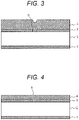
- FIG. 3 is a cross-sectional view of a main part taken along line A-A in FIG. 1 in the manufacturing process of the fuel battery cell 1.
- the semiconductor substrate 2 made of single crystal Si and having a Si ⁇ 100> crystal orientation is prepared, and the first insulating film 3 is formed.
- the semiconductor substrate 2 has a thickness of 400 ⁇ m or more.
- a silicon nitride film having a tensile stress of about 200 nm is formed by a CVD method. In the case of the CVD method, a silicon nitride film having the same thickness is also formed on the back side of the semiconductor substrate 2.
- a silicon oxide film is formed to be thicker than the first insulating film 3 by using, for example, the CVD method.
- FIG. 4 illustrates a next manufacturing process of the fuel battery cell 1.
- the first insulating film 3 is planarized by the chemical mechanical polishing (CMP) so as to reduce the step, and a stacked film of the first insulating film 3 and the second insulating film 4 is formed.
- the film thickness of the second insulating film 4 after the CMP is, for example, about 200 nm.
- FIG. 5 illustrates a next manufacturing process of the fuel battery cell 1.
- a metal film for example, a platinum film (Pt) is formed in a thickness of about 20 nm by a sputtering method, patterning is performed using a photolithography method, and the first electrode 5 is formed using a dry etching method with an Ar (argon) gas or the like.
- Ar argon
- a titanium film (Ti) of about 2 nm as a barrier metal film that assists adhesion.
- a pattern of a negative resist is formed by a photolithography technique, and a YSZ film (zirconium oxide film containing yttrium) is formed with a thickness of 500 nm or less as the electrolyte film 6 by a sputtering method.
- the flatness of the second insulating film 4 is good, the crystallinity of the YSZ film is good even through the first electrode 5, and a film with less electron leakage can be obtained even if the YSZ film is formed thin to about 100 nm, for example.
- a Pt film of about 20 nm is formed by a sputtering method, patterning is performed by a photolithography method, and the second electrode 7 is formed by dry etching with Ar gas. Subsequently, the back surface of the semiconductor substrate 2 is exposed to the first insulating film 3 on the back surface of the semiconductor substrate 2 using a photolithography technique and an insulating film etching technique.
- FIG. 6 illustrates a next manufacturing process of the fuel battery cell 1.
- the Si film of the semiconductor substrate 2 is removed by wet etching with a KOH (potassium hydroxide) solution or a TMAH (tetramethylamide) solution or dry etching using a fluorine-based gas as a main component to form the first opening 8. Since the first insulating film 3 and the first electrode 5 have a sufficient etching selectivity, the first insulating film 3 and the first electrode 5 remain as an etching stopper even after completion of etching of the semiconductor substrate 2.
- KOH potassium hydroxide
- TMAH tetramethylamide
- the second insulating film 4 inside the second opening 9 and on the second opening 9 is removed by fluorine-based wet etching to form the fuel battery cell 1. Since the wet etching is isotropic, the wet etching proceeds not only on the surface in contact with the second opening 9 but also in the lateral direction, and the area of the third opening 10 can be controlled according to the liquid temperature and time.
- the first electrode 5 is provided on the third opening 10, and the electrolyte film 6 is not corroded by forming the first electrode 5 as a metal film having chemical resistance to fluorine-based materials.
- the first electrode 5 and the second electrode 7 may be films having excellent fluorine-based chemical resistance, low resistivity, and a melting point higher than the use temperature (for example, 600°C or higher), and examples thereof include a silver film (Ag), a nickel film (Ni), a chromium film (Cr), a palladium film (Pd), a ruthenium film (Ru), and a rhodium film (Rh) in addition to the Pt film.
- the first insulating film 3 is not limited to a silicon nitride film, and may be a film having tensile stress with respect to the Si substrate, such as an aluminum nitride film.
- the second insulating film 4 may be a silicon oxide film containing boron or phosphorus, or a P-TEOS film containing an organic component at a low temperature.
- the relationship of the second opening 9 with respect to the third opening 10 serving as a power generation region will be described.
- the first opening 8, the second opening 9, and the third opening 10 have the same area, when one side of the opening is about 300 ⁇ m due to the difference in film stress from the semiconductor substrate 2, deflection (upwardly convex shape) of about 6 ⁇ m occurs, and film breakage is likely to occur. Therefore, there is a problem that the area of the opening cannot be increased and the power generation output per substrate cannot be increased. Therefore, it is important not to cause deflection in the stacked film of the electrolyte film 6 sandwiched between the electrodes.
- FIG. 7 illustrates a result of evaluating a deflection amount by changing the area of the second opening 9 with respect to the third opening 10.
- one side of the first opening 8 is set to about 500 ⁇ m
- the diameter of the third opening 10 is set to about 300 ⁇ m
- the deflection amount of the film is measured while the second opening 9 is changed to 50 ⁇ m, 150 ⁇ m, and 300 ⁇ m (almost the same area as the third opening 10).
- the deflection amount decreases as the area of the second opening 9 decreases.
- the second opening 9 has a small area even if the third opening 10 is provided, the balance of the film stress between the first insulating film 3 and the stacked film of the electrolyte film 6 with the electrode interposed therebetween is maintained, a membrane structure having excellent heat resistance can be formed, and high power generation output can be achieved by increasing the area of the third opening serving as a power generation region.
- FIG. 8 is a cross-sectional view of the fuel battery cell 1 according to a second embodiment of the present invention.
- the first insulating film 3, the first electrode 5, the electrolyte film 6, and the second electrode 7 are the same as those in the first embodiment.
- the difference from the first embodiment is that the second insulating film 4 and a third insulating film 12 are stacked on the first insulating film 3, and the side wall shape of the third opening 10 becomes wider from the first insulating film 3 toward the first electrode 5.
- the second insulating film 4 is processed into a tapered shape by wet etching, and then, for example, a silicon nitride film is formed as the third insulating film 12, and the side wall is covered so that the second insulating film 4 is not exposed in the third opening 10.
- a silicon oxide film is formed as a sacrificial film above the step, and planarization is performed by CMP with the third insulating film 12 as a stopper.
- the processes of forming the first electrode 5, the electrolyte film 6, and the second electrode 7, and forming the first opening 8 on the back surface are the same as those in the first embodiment.
- the third opening 10 can be manufactured in a constant area in the wafer or between the wafers. Since the variation in power generation output can be reduced by suppressing the variation in the third opening 10, it is possible to save time and effort for adjustment when the fuel battery cell 1 is connected in series or in parallel and supplied to the outside. In addition, the film strength in the first opening 8 can be improved by providing the third insulating film 12, and the third opening 10 can be widened by providing the taper, so that the power generation output can be expected to be improved.
- the third opening 10 has a tapered side wall.
- the third insulating film 12 preferably has fluorine-based wet etching resistance and tensile stress, and may be an aluminum nitride film or the like.
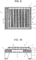
- FIG. 9 is a plan view of the fuel battery cell 1 according to a third embodiment of the present invention.
- the shapes of the first electrode 5, the electrolyte film 6, and the second electrode 7 are the same as those in the first and second embodiments.
- a plurality of circular second openings 9 having a small area is arranged in the first insulating film 3 in the first opening 8, and the first electrode 5 appears to be exposed in the second opening 9.
- the first opening 8 has a rectangular shape in plan view, and a length of one side is, for example, about 500 ⁇ m.
- the second opening 9 has a circular shape having a diameter of about 1 ⁇ m, and the second openings 9 adjacent to each other are arranged so as to be substantially equal to each other at a distance of about 1 ⁇ m.
- the opening size of the third opening 10 is formed to the outside of both outermost ends of the plurality of aligned second openings 9.
- the planar shape of the third opening 10 may not be a straight line, but is close to a rectangle and has a side length of about 300 ⁇ m.
- the relationship between the opening areas is the first opening 8 > the third opening 10 > the second opening 9, which is the same as that in the first and second embodiments.
- FIG. 10 is a cross-sectional view taken along line B-B in FIG. 9 .
- a plurality of second openings 9 are formed side by side in the first insulating film 3, and the opening size of the third opening 10 formed in the second insulating film 4 thereon is larger than the outermost ends of the plurality of second openings 9.
- the third opening 10 is formed by removing the second openings 9 adjacent to each other and a silicon oxide film (not illustrated) serving as a sacrificial layer on the upper surface at the time of fluorine-based wet etching after forming the first opening 8.
- the third opening 10 can be enlarged to the outside of the second opening 9, the side wall of the third opening 10 is stopped by the third insulating film 12, and the area of the third opening 10 can be made constant. This can reduce variations in power generation output.
- the etching time can be shortened, the inflow and outflow of the gas can be further enhanced, and the power generation output can be further stabilized.
- the substantial opening area through which the fuel gas flows in and out can be widened by arranging the plurality of second openings 9, so that the gas flows in and out from the first opening 8 side into the third opening 10 more easily than the fuel battery cell 1 of the first and second embodiments, and the stable power generation output can be obtained.
- FIG. 11 is a plan view of the fuel battery cell 1 according to a fourth embodiment of the present invention.
- the shapes of the first electrode 5, the electrolyte film 6, and the second electrode 7 are the same as those in the third embodiment.
- a plurality of circular second openings 9 having a small area is arranged in the first insulating film 3 in the first opening 8, and the first electrode 5 appears to be exposed in the second opening 9.
- the difference from the third embodiment is that there are a plurality of third openings 10.
- the first opening 8 has a rectangular shape in plan view, and has a side length of about 5 mm, for example.
- the second opening 9 has a circular shape having a diameter of about 1 ⁇ m, and the second openings 9 adjacent to each other are arranged so as to be substantially equal to each other at a distance of about 1 ⁇ m.
- the third openings 10 each have a rectangular shape with a side length of about 300 ⁇ m, and an interval between the third openings 10 is about 100 ⁇ m.
- the relationship between the opening areas is the first opening 8 > the third opening 10 > the second opening 9, which is the same as that in the first and second embodiments.
- the shape of the third opening 10 is rectangular, but by forming the third opening into a polygonal shape such as a circular shape or a hexagonal shape, the third opening is efficiently spread in the first opening 8 to increase the area of the power generation region, and the power generation output can be increased.
- FIG. 12 is a cross-sectional view taken along line C-C in FIG. 11 .
- the plurality of third openings 10 in which the plurality of second openings 9 are arranged are formed in the first insulating film 3.
- the third insulating film 12 is disposed on the side wall of the third opening 10, so that the area of the third opening 10 can be made constant, and variation in power generation output can be reduced.
- the area of the power generation region can be further widened by changing the shape of the third opening 10 to a hexagonal shape or the like and narrowing the interval while considering the stress of the entire first opening 8, and high power generation output can be achieved.
- the fuel battery cell according to the fourth embodiment has a structure in which the plurality of third openings 10 in the third embodiment are provided in the first opening 8. As a result, the contact area between the gas and the first electrode 5 is increased, and a high power generation output can be obtained.
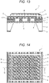
- FIG. 13 is a cross-sectional view of the fuel battery cell 1 according to a fifth embodiment of the present invention.
- the fuel battery cell according to the fifth embodiment has a stress adjustment film 15 between the third opening 10 and the first electrode 5.
- the shape of the third opening 10 is the same as that of the third embodiment, but the stress adjustment film 15 is formed so as to cover at least the third opening 10.
- the stress adjustment film 15 is formed of, for example, aluminum nitride or the like, has a columnar crystal structure in which a grain boundary extends along a film thickness direction, has a thin film thickness of about 50 nm, is a continuous film, and is a film through which fuel gas, air, or the like passes.
- the stress adjustment film 15 is a fluorine-based film having tensile stress with respect to the semiconductor substrate 2 and excellent chemical resistance, and has a good stress balance with the electrolyte film 6 having compressive stress while maintaining power generation output, and heat resistance is improved.
- FIG. 14 is a plan view of the fuel battery cell 1 according to a sixth embodiment of the present invention.
- a third electrode 20 and the second electrode 7 are separately formed as the same layer on the electrolyte film 6.
- the third electrode 20 is disposed so as to be fitted in a contact hole 19 formed in the electrolyte film 6.
- a plurality of second openings 9 are disposed in the first opening 8, and the first electrode 5 is exposed through the third opening 10.
- a plurality of third openings 10 are also arranged, which is similar to that in the fourth embodiment.
- FIG. 15 is a cross-sectional view taken along line D-D in FIG. 14 .
- the first opening 8 is formed in the semiconductor substrate 2
- the first insulating film 3, a fourth insulating film 17, and a fifth insulating film 18 are continuously formed thereon, and the second opening 9 is provided so as to penetrate the first insulating film 3, the fourth insulating film 17, and the fifth insulating film 18.
- the fourth insulating film 17 is, for example, a silicon oxide film having a compressive stress
- the fifth insulating film 18 is, for example, a silicon nitride film having a tensile stress.
- the overall film strength on the first opening 8 is improved. Further, the balance of the film strength with the stacked film of the first electrode, the electrolyte film 6, and the second electrode 7 on the third opening 10 is improved, and the heat resistance is improved.
- the electrolyte film 6 is formed so as to cover the first electrode 5, and after only a part of the contact hole 19 is processed for external output, the third electrode 20 is formed on the same layer as the second electrode 7.
- the first electrode 5 and the third electrode 20 are connected by the plurality of contact holes 19 formed, and are separated from the second electrode 7.
- a lower pedestal 22 made of ceramic or metal is provided in order to form a gas flow path, and confidentiality is maintained using an adhesive or sealing material.
- a gas pipe 26 for inflow and outflow of gas is connected to the pedestal 22, and is connected to the first opening 8.
- An upper lid substrate 25 provided with wirings 23 and 24 is placed on an upper side where electrode terminals of the fuel battery cell 1 are located in order to form an air flow path.
- the material of the upper lid substrate 25 is also ceramic or metal.
- the wiring 23 is connected to the third electrode 20, and the wiring 24 is connected to the second electrode 7.
- the wiring 23 and the wiring 24 can be connected to a device that consumes power from the fuel battery cell 21 via a device that controls power generation (not illustrated) or the like.
- a device that controls power generation not illustrated
- the wirings 23 and 24 are separated from each other and are not electrically connected to each other.
- a pipe for introducing gas different from the first opening 8 may be connected to the upper lid substrate 25.
- the height from the semiconductor substrate 2 to the upper surface of the third electrode 20 is substantially equal to the height from the semiconductor substrate 2 to the upper surface of the second electrode 7.
- the contact between the third electrode 20 and the wiring 23 is improved, the contact between the second electrode 7 and the wiring 24 is improved, and the power generation loss can be reduced. Since these heights are substantially equal, the air flow path can be hermetically sealed by the upper lid substrate 25. Further, since the fuel battery cell 1 serves as a partition wall so that hydrogen gas and air are not mixed, and the output electrode is provided on the side to which air is supplied, there is no possibility that the electrode (the first electrode 5 or the second electrode 7) is corroded, and there is no possibility that hydrogen gas is ignited.
- the fuel battery cell 21 is bonded onto the upper lid substrate 25, and the upper lid substrate 25 is stacked thereon. Therefore, the plurality of the fuel battery cell 1 are stacked, so that the power generation amount can be improved.
- a flow path for supplying hydrogen gas is formed on the upper surface (the surface facing the surface to which air is supplied) side of the upper lid substrate 25, similarly to the pedestal 22.
- the pedestal 22 and the upper lid substrate 25 need to be fastened from the outside with a jig or the like on the upper and lower sides in order to maintain confidentiality.
- FIG. 16 is a side cross-sectional view for explaining a configuration of a fuel battery cell system according to a seventh embodiment of the present invention.
- the fuel battery cell 1 has been described in any one of the first to sixth embodiments.
- the fuel battery cell 1 is arranged in an array, and an air chamber is formed above the fuel battery cell 1. Air is introduced into the air chamber through an air introduction port and discharged from an air exhaust port.
- the fuel chamber is formed below the fuel battery cell 1.
- Fuel gas is introduced into the fuel chamber through a fuel introduction port and discharged from a fuel discharge port.
- the fuel battery cell 1 is connected to an external load via a connection portion.
- the present invention is not limited to the embodiments described above, and may include various modifications.
- the above embodiments of the present invention are described in detail to explain in a clearly understandable way, and are not necessarily limited to those having all the described configurations.
- some of the configurations of a certain embodiment may be replaced with the configurations of the other embodiments, and the configurations of the other embodiments may be added to the configurations of a certain embodiment.
- some of the configurations of each embodiment may be omitted, replaced with other configurations, or added to other configurations.
- the opening area is an opening area when viewed from below in FIG. 2 (that is, when viewed in a direction from the first opening 8 to the third opening 10).
Landscapes
- Engineering & Computer Science (AREA)
- Manufacturing & Machinery (AREA)
- Life Sciences & Earth Sciences (AREA)
- Sustainable Development (AREA)
- Sustainable Energy (AREA)
- Chemical & Material Sciences (AREA)
- Chemical Kinetics & Catalysis (AREA)
- Electrochemistry (AREA)
- General Chemical & Material Sciences (AREA)
- Fuel Cell (AREA)
Abstract
Description
- The present invention relates to a fuel battery cell.
- In recent years, fuel cells have attracted attention as clean energy sources capable of high energy conversion and not discharging pollutants such as carbon dioxide gas and nitrogen oxides. Among fuel cells, a solid electrolyte fuel cell (hereinafter, abbreviated as SOFC (Solid Oxide Fuel Cell)) has high power generation efficiency and can use gases such as hydrogen, methane, and carbon monoxide, which are easy to handle, as a fuel. Therefore, the solid electrolyte fuel cell has many advantages as compared with other systems, and is expected as a cogeneration system which is excellent in energy saving and environmental performance. The SOFC has a structure in which a solid electrolyte is sandwiched between a fuel electrode and an air electrode, and fuel gas such as hydrogen is supplied to the fuel electrode side using the electrolyte as a partition wall, and air or oxygen gas is supplied.
- In
PTL 1, a through window is formed in a single crystal silicon substrate, and a manifold substrate supplied from a fuel gas reformer is connected to a substrate in which a porous thick film, a fuel electrode, an electrolyte film, and an air electrode are stacked in this order in a through window. This document provides a silicon-based SOFC capable of low-temperature operation (350 to 600°C) with this structure. - The silicon-based SOFC disclosed in
PTL 1 has a set of electrodes including an anode and a cathode via a thick film porous structure having mechanical strength on a substrate provided with a through window. Further, a thin film electrolyte is provided between the electrodes. The thick film porous structure in the same document is provided with pores serving as a gas flow path, but the pores are made sufficiently small so that the inside of the pores is not blocked by the electrode material formed on the thick film porous structure. - PTL 1:
JP 2005-532661 A - In
PTL 1, the through window provided in the silicon substrate is larger than the pore provided in the thick film porous structure, and the pore in the manifold substrate is larger than the through window in the silicon substrate. Therefore, there is a problem that the flow path of the fuel gas becomes narrower from the pores in the manifold substrate toward the electrode on the thick film porous structure, the effective area of the small pores of the thick film porous structure contributing to power generation narrows, and the power generation amount per substrate decreases. - The present invention has been made in view of the above problems, and an object of the present invention is to provide a fuel battery cell having a high power generation output by increasing an area of an effective power generation region contributing to power generation while ensuring mechanical strength of the fuel battery cell.
- A fuel battery cell according to the present invention is provided with a first and a second insulating films between a support substrate and a first electrode. The support substrate has a first opening, the first insulating film has a second opening, and the second insulating film has a third opening. An opening area of the first opening is larger than that of the second opening, and an opening area of the third opening is larger than that of the second opening.
- According to a fuel battery cell of the present invention, it is possible to increase an area of an effective power generation region contributing to power generation while ensuring the mechanical strength of the fuel battery cell. Other objects and novel features will become apparent from the description of the specification and the accompanying drawings.
-
- [
FIG. 1] FIG. 1 is a plan view of afuel battery cell 1 according to a first embodiment. - [
FIG. 2] FIG. 2 is a cross-sectional view taken along line A-A inFIG. 1 . - [
FIG. 3] FIG. 3 is a cross-sectional view of a main part taken along line A-A inFIG. 1 in a manufacturing process of thefuel battery cell 1. - [
FIG. 4] FIG. 4 shows a next manufacturing process of thefuel battery cell 1. - [
FIG. 5] FIG. 5 shows a next manufacturing process of thefuel battery cell 1. - [
FIG. 6] FIG. 6 shows a next manufacturing process of thefuel battery cell 1. - [
FIG. 7] FIG. 7 illustrates a result of evaluating a deflection amount by changing an area of asecond opening 9 with respect to athird opening 10. - [
FIG. 8] FIG. 8 is a cross-sectional view of thefuel battery cell 1 according to a second embodiment. - [
FIG. 9] FIG. 9 is a plan view of thefuel battery cell 1 according to a third embodiment. - [
FIG. 10] FIG. 10 is a cross-sectional view taken along line B-B inFIG. 9 . - [
FIG. 11] FIG. 11 is a plan view of thefuel battery cell 1 according to a fourth embodiment. - [
FIG. 12] FIG. 12 is a cross-sectional view taken along line C-C inFIG. 11 . - [
FIG. 13] FIG. 13 is a cross-sectional view of thefuel battery cell 1 according to a fifth embodiment. - [
FIG. 14] FIG. 14 is a plan view of thefuel battery cell 1 according to a sixth embodiment. - [
FIG. 15] FIG. 15 is a cross-sectional view taken along line D-D inFIG. 14 . - [
FIG. 16] FIG. 16 is a side cross-sectional view for explaining a configuration of a fuel battery system according to a seventh embodiment. -
FIG. 1 is a plan view of afuel battery cell 1 according to a first embodiment of the present invention. As illustrated inFIG. 1 , in thefuel battery cell 1, afirst electrode 5 is formed on a firstinsulating film 3 and a secondinsulating film 4 formed on asemiconductor substrate 2 made of single crystal silicon (Si). The upper surface of the secondinsulating film 4 is covered with thefirst electrode 5 and covered with anelectrolyte film 6 so as to expose a part of thefirst electrode 5. Asecond electrode 7 is formed inside thefirst electrode 5 and theelectrolyte film 6. In the case of the plan view seen from the upper surface, no opening is seen hidden by thefirst electrode 5 and thesecond electrode 7, but in the plan view seen from the lower surface (first opening 8 side), the firstinsulating film 3 having asecond opening 9 is seen in thefirst opening 8 of thesemiconductor substrate 2. Since the firstinsulating film 3 is transparent, a third opening 10 having an area larger than that of thesecond opening 9 can also be observed. Thefirst electrode 5 and thesecond electrode 7 serve as an anode or cathode electrode, and are connected to the outside to supply power generated by thefuel battery cell 1 to the outside. -
FIG. 2 is a cross-sectional view taken along line A-A inFIG. 1 . As illustrated inFIG. 2 , thesemiconductor substrate 2 has thefirst opening 8 from which the inside is removed, and has a shape in which a silicon nitride film having, for example, tensile stress is exposed as the firstinsulating film 3 on thefirst opening 8. In the firstinsulating film 3, thesecond opening 9 is provided so as to communicate with thefirst opening 8. On the firstinsulating film 3, for example, a silicon oxide film having a compressive stress is formed as the secondinsulating film 4, and the third opening 10 having a larger area than thesecond opening 9 is provided. The third opening 10 communicates with thesecond opening 9. - The
first opening 8 has a rectangular shape in plan view, and the length of one side is about 0.2 mm to 5 mm. Thesecond opening 9 is, for example, circular and has a diameter of about 0.5 µm to 50 µm. Thethird opening 10 is, for example, circular and has a diameter of about 50 µm to 500 µm. The relationship between the opening areas is the first opening 8 > the third opening 10 > the second opening 9. - The first
insulating film 3 and the secondinsulating film 4 are stacked on thesemiconductor substrate 2, and function as a support portion that supports thefirst electrode 5, an electrolyte film, and thesecond electrode 7. Thefirst electrode 5 is formed on the secondinsulating film 4 so as to cover at least thefirst opening 8. Therefore, thefirst electrode 5 is exposed to the first opening 8 side in the third opening 10, and has a structure in contact with fuel gas or air. Theelectrolyte film 6 on thefirst electrode 5 is disposed so as to cover thefirst opening 8 and to expose a part of thefirst electrode 5. Thesecond electrode 7 on theelectrolyte film 6 is formed via theelectrolyte film 6 so as to cover thefirst opening 8 and not to be connected to thefirst electrode 5. - With this structure, the stress due to the thermal expansion of the
semiconductor substrate 2 in the environment of the operating temperature is dispersed and applied to the upper and lower films (that is, the firstinsulating film 3 and a stacked film of thefirst electrode 5 to the second electrode 7) of the third opening 10. Therefore, even if there is a cavity of thethird opening 10, it is not damaged. In addition, since the entirefirst opening 8 is formed by the first insulatingfilm 3 and the secondinsulating film 4, and the stacked film of thefirst electrode 5 to thesecond electrode 7, the stress due to the thermal expansion of thesemiconductor substrate 2 can be mitigated. It is confirmed that when a sample in which thefirst opening 8, thesecond opening 9, and thethird opening 10 have the same area is prepared, since theelectrolyte film 6 has compressive stress with respect to thesemiconductor substrate 2, deflection occurs in the stacked film including theelectrolyte film 6 in the opening, and there is a problem in heat resistance. -
FIG. 3 is a cross-sectional view of a main part taken along line A-A inFIG. 1 in the manufacturing process of thefuel battery cell 1. First, as illustrated inFIG. 3 , thesemiconductor substrate 2 made of single crystal Si and having a Si <100> crystal orientation is prepared, and the first insulatingfilm 3 is formed. Thesemiconductor substrate 2 has a thickness of 400 µm or more. As the first insulatingfilm 3, for example, a silicon nitride film having a tensile stress of about 200 nm is formed by a CVD method. In the case of the CVD method, a silicon nitride film having the same thickness is also formed on the back side of thesemiconductor substrate 2. Next, patterning is performed on the first insulatingfilm 3 on the front side by using a photolithography technique, and a part of the first insulatingfilm 3 is removed. The region to be removed is a region corresponding to thesecond opening 9 serving as an inlet/outlet port for fuel gas or air. Next, as the secondinsulating film 4, a silicon oxide film is formed to be thicker than the first insulatingfilm 3 by using, for example, the CVD method. -
FIG. 4 illustrates a next manufacturing process of thefuel battery cell 1. As illustrated inFIG. 4 , the first insulatingfilm 3 is planarized by the chemical mechanical polishing (CMP) so as to reduce the step, and a stacked film of the first insulatingfilm 3 and the secondinsulating film 4 is formed. The film thickness of the secondinsulating film 4 after the CMP is, for example, about 200 nm. -
FIG. 5 illustrates a next manufacturing process of thefuel battery cell 1. As illustrated inFIG. 5 , a metal film, for example, a platinum film (Pt) is formed in a thickness of about 20 nm by a sputtering method, patterning is performed using a photolithography method, and thefirst electrode 5 is formed using a dry etching method with an Ar (argon) gas or the like. At this time, in order to improve the adhesive force between the Pt film and the secondinsulating film 4, it is also desirable to modify the surface of the secondinsulating film 4 as a base by, for example, about 10 to 15 nm etching by sputter etching with Ar gas before the formation of the Pt film. Alternatively, it is also desirable to form a titanium film (Ti) of about 2 nm as a barrier metal film that assists adhesion. Next, a pattern of a negative resist is formed by a photolithography technique, and a YSZ film (zirconium oxide film containing yttrium) is formed with a thickness of 500 nm or less as theelectrolyte film 6 by a sputtering method. In the first embodiment, since the flatness of the secondinsulating film 4 is good, the crystallinity of the YSZ film is good even through thefirst electrode 5, and a film with less electron leakage can be obtained even if the YSZ film is formed thin to about 100 nm, for example. Next, for example, a Pt film of about 20 nm is formed by a sputtering method, patterning is performed by a photolithography method, and thesecond electrode 7 is formed by dry etching with Ar gas. Subsequently, the back surface of thesemiconductor substrate 2 is exposed to the first insulatingfilm 3 on the back surface of thesemiconductor substrate 2 using a photolithography technique and an insulating film etching technique. -
FIG. 6 illustrates a next manufacturing process of thefuel battery cell 1. As illustrated inFIG. 6 , with the patterned first insulatingfilm 3 on the back surface of thesemiconductor substrate 2 as a mask, the Si film of thesemiconductor substrate 2 is removed by wet etching with a KOH (potassium hydroxide) solution or a TMAH (tetramethylamide) solution or dry etching using a fluorine-based gas as a main component to form thefirst opening 8. Since the first insulatingfilm 3 and thefirst electrode 5 have a sufficient etching selectivity, the first insulatingfilm 3 and thefirst electrode 5 remain as an etching stopper even after completion of etching of thesemiconductor substrate 2. - Next, the second
insulating film 4 inside thesecond opening 9 and on thesecond opening 9 is removed by fluorine-based wet etching to form thefuel battery cell 1. Since the wet etching is isotropic, the wet etching proceeds not only on the surface in contact with thesecond opening 9 but also in the lateral direction, and the area of thethird opening 10 can be controlled according to the liquid temperature and time. In addition, thefirst electrode 5 is provided on thethird opening 10, and theelectrolyte film 6 is not corroded by forming thefirst electrode 5 as a metal film having chemical resistance to fluorine-based materials. - The
first electrode 5 and thesecond electrode 7 may be films having excellent fluorine-based chemical resistance, low resistivity, and a melting point higher than the use temperature (for example, 600°C or higher), and examples thereof include a silver film (Ag), a nickel film (Ni), a chromium film (Cr), a palladium film (Pd), a ruthenium film (Ru), and a rhodium film (Rh) in addition to the Pt film. - The first
insulating film 3 is not limited to a silicon nitride film, and may be a film having tensile stress with respect to the Si substrate, such as an aluminum nitride film. The secondinsulating film 4 may be a silicon oxide film containing boron or phosphorus, or a P-TEOS film containing an organic component at a low temperature. - Next, the relationship of the
second opening 9 with respect to thethird opening 10 serving as a power generation region will be described. As described above, if thefirst opening 8, thesecond opening 9, and thethird opening 10 have the same area, when one side of the opening is about 300 µm due to the difference in film stress from thesemiconductor substrate 2, deflection (upwardly convex shape) of about 6 µm occurs, and film breakage is likely to occur. Therefore, there is a problem that the area of the opening cannot be increased and the power generation output per substrate cannot be increased. Therefore, it is important not to cause deflection in the stacked film of theelectrolyte film 6 sandwiched between the electrodes. -
FIG. 7 illustrates a result of evaluating a deflection amount by changing the area of thesecond opening 9 with respect to thethird opening 10. In the sample, one side of thefirst opening 8 is set to about 500 µm, the diameter of thethird opening 10 is set to about 300 µm, and the deflection amount of the film is measured while thesecond opening 9 is changed to 50 µm, 150 µm, and 300 µm (almost the same area as the third opening 10). As can be seen from this drawing, even if thethird opening 10 is the same, the deflection amount decreases as the area of thesecond opening 9 decreases. In addition, it has also been confirmed that when the sample is heat-treated at 500°C or higher, the smaller thesecond opening 9 is, the less likely it is to be damaged. - As described above, when the
second opening 9 has a small area even if thethird opening 10 is provided, the balance of the film stress between the first insulatingfilm 3 and the stacked film of theelectrolyte film 6 with the electrode interposed therebetween is maintained, a membrane structure having excellent heat resistance can be formed, and high power generation output can be achieved by increasing the area of the third opening serving as a power generation region. -
FIG. 8 is a cross-sectional view of thefuel battery cell 1 according to a second embodiment of the present invention. As illustrated inFIG. 8 , the first insulatingfilm 3, thefirst electrode 5, theelectrolyte film 6, and thesecond electrode 7 are the same as those in the first embodiment. The difference from the first embodiment is that the secondinsulating film 4 and a third insulatingfilm 12 are stacked on the first insulatingfilm 3, and the side wall shape of thethird opening 10 becomes wider from the first insulatingfilm 3 toward thefirst electrode 5. - In manufacturing the structure of
FIG. 8 , after the secondinsulating film 4 is formed, the secondinsulating film 4 is processed into a tapered shape by wet etching, and then, for example, a silicon nitride film is formed as the third insulatingfilm 12, and the side wall is covered so that the secondinsulating film 4 is not exposed in thethird opening 10. Thereafter, although not illustrated, a silicon oxide film is formed as a sacrificial film above the step, and planarization is performed by CMP with the third insulatingfilm 12 as a stopper. The processes of forming thefirst electrode 5, theelectrolyte film 6, and thesecond electrode 7, and forming thefirst opening 8 on the back surface are the same as those in the first embodiment. - By preventing the second
insulating film 4 from being exposed in thethird opening 10, even if the time of fluorine-based wet etching after the formation of thefirst opening 8 is lengthened, the secondinsulating film 4 is stopped by the third insulatingfilm 12 and does not spread outward. Therefore, thethird opening 10 can be manufactured in a constant area in the wafer or between the wafers. Since the variation in power generation output can be reduced by suppressing the variation in thethird opening 10, it is possible to save time and effort for adjustment when thefuel battery cell 1 is connected in series or in parallel and supplied to the outside. In addition, the film strength in thefirst opening 8 can be improved by providing the third insulatingfilm 12, and thethird opening 10 can be widened by providing the taper, so that the power generation output can be expected to be improved. - In the second embodiment, the
third opening 10 has a tapered side wall. However, even when the secondinsulating film 4 is processed by dry etching to have a substantially vertical structure of 85° or more, a similar effect can be obtained by improving the coverage of the third insulatingfilm 12. The thirdinsulating film 12 preferably has fluorine-based wet etching resistance and tensile stress, and may be an aluminum nitride film or the like. -
FIG. 9 is a plan view of thefuel battery cell 1 according to a third embodiment of the present invention. As illustrated inFIG. 9 , in plan view from the upper surface, the shapes of thefirst electrode 5, theelectrolyte film 6, and thesecond electrode 7 are the same as those in the first and second embodiments. However, when viewed from the lower side, a plurality of circularsecond openings 9 having a small area is arranged in the first insulatingfilm 3 in thefirst opening 8, and thefirst electrode 5 appears to be exposed in thesecond opening 9. - The
first opening 8 has a rectangular shape in plan view, and a length of one side is, for example, about 500 µm. For example, it is desirable that thesecond opening 9 has a circular shape having a diameter of about 1 µm, and thesecond openings 9 adjacent to each other are arranged so as to be substantially equal to each other at a distance of about 1 µm. The opening size of thethird opening 10 is formed to the outside of both outermost ends of the plurality of alignedsecond openings 9. The planar shape of thethird opening 10 may not be a straight line, but is close to a rectangle and has a side length of about 300 µm. The relationship between the opening areas is thefirst opening 8 > thethird opening 10 > thesecond opening 9, which is the same as that in the first and second embodiments. -
FIG. 10 is a cross-sectional view taken along line B-B inFIG. 9 . InFIG. 10 , as compared with the second embodiment, in thefuel battery cell 1, a plurality ofsecond openings 9 are formed side by side in the first insulatingfilm 3, and the opening size of thethird opening 10 formed in the secondinsulating film 4 thereon is larger than the outermost ends of the plurality ofsecond openings 9. Similarly to the second embodiment, thethird opening 10 is formed by removing thesecond openings 9 adjacent to each other and a silicon oxide film (not illustrated) serving as a sacrificial layer on the upper surface at the time of fluorine-based wet etching after forming thefirst opening 8. Therefore, thethird opening 10 can be enlarged to the outside of thesecond opening 9, the side wall of thethird opening 10 is stopped by the third insulatingfilm 12, and the area of thethird opening 10 can be made constant. This can reduce variations in power generation output. When the interval between the adjacentsecond openings 9 is narrowed, the etching time can be shortened, the inflow and outflow of the gas can be further enhanced, and the power generation output can be further stabilized. - In the fuel battery cell of the third embodiment, the substantial opening area through which the fuel gas flows in and out can be widened by arranging the plurality of
second openings 9, so that the gas flows in and out from thefirst opening 8 side into thethird opening 10 more easily than thefuel battery cell 1 of the first and second embodiments, and the stable power generation output can be obtained. -
FIG. 11 is a plan view of thefuel battery cell 1 according to a fourth embodiment of the present invention. As illustrated inFIG. 11 , in plan view from the upper surface, the shapes of thefirst electrode 5, theelectrolyte film 6, and thesecond electrode 7 are the same as those in the third embodiment. However, when viewed from the lower side, a plurality of circularsecond openings 9 having a small area is arranged in the first insulatingfilm 3 in thefirst opening 8, and thefirst electrode 5 appears to be exposed in thesecond opening 9. The difference from the third embodiment is that there are a plurality ofthird openings 10. - The
first opening 8 has a rectangular shape in plan view, and has a side length of about 5 mm, for example. For example, it is desirable that thesecond opening 9 has a circular shape having a diameter of about 1 µm, and thesecond openings 9 adjacent to each other are arranged so as to be substantially equal to each other at a distance of about 1 µm. Thethird openings 10 each have a rectangular shape with a side length of about 300 µm, and an interval between thethird openings 10 is about 100 µm. The relationship between the opening areas is thefirst opening 8 > thethird opening 10 > thesecond opening 9, which is the same as that in the first and second embodiments. - In
FIG. 11 , the shape of thethird opening 10 is rectangular, but by forming the third opening into a polygonal shape such as a circular shape or a hexagonal shape, the third opening is efficiently spread in thefirst opening 8 to increase the area of the power generation region, and the power generation output can be increased. -
FIG. 12 is a cross-sectional view taken along line C-C inFIG. 11 . InFIG. 12 , as compared with the third embodiment, in thefuel battery cell 1 according to the fourth embodiment, as described above, the plurality ofthird openings 10 in which the plurality ofsecond openings 9 are arranged are formed in the first insulatingfilm 3. As with the third embodiment, the third insulatingfilm 12 is disposed on the side wall of thethird opening 10, so that the area of thethird opening 10 can be made constant, and variation in power generation output can be reduced. In addition, the area of the power generation region can be further widened by changing the shape of thethird opening 10 to a hexagonal shape or the like and narrowing the interval while considering the stress of the entirefirst opening 8, and high power generation output can be achieved. - The fuel battery cell according to the fourth embodiment has a structure in which the plurality of
third openings 10 in the third embodiment are provided in thefirst opening 8. As a result, the contact area between the gas and thefirst electrode 5 is increased, and a high power generation output can be obtained. -
FIG. 13 is a cross-sectional view of thefuel battery cell 1 according to a fifth embodiment of the present invention. The fuel battery cell according to the fifth embodiment has astress adjustment film 15 between thethird opening 10 and thefirst electrode 5. As illustrated inFIG. 13 , the shape of thethird opening 10 is the same as that of the third embodiment, but thestress adjustment film 15 is formed so as to cover at least thethird opening 10. Thestress adjustment film 15 is formed of, for example, aluminum nitride or the like, has a columnar crystal structure in which a grain boundary extends along a film thickness direction, has a thin film thickness of about 50 nm, is a continuous film, and is a film through which fuel gas, air, or the like passes. Thestress adjustment film 15 is a fluorine-based film having tensile stress with respect to thesemiconductor substrate 2 and excellent chemical resistance, and has a good stress balance with theelectrolyte film 6 having compressive stress while maintaining power generation output, and heat resistance is improved. -
FIG. 14 is a plan view of thefuel battery cell 1 according to a sixth embodiment of the present invention. As illustrated inFIG. 14 , in order to dispose the output terminals to the outside of afuel battery cell 21 in the sixth embodiment at the same height, athird electrode 20 and thesecond electrode 7 are separately formed as the same layer on theelectrolyte film 6. Thethird electrode 20 is disposed so as to be fitted in acontact hole 19 formed in theelectrolyte film 6. When viewed from the lower surface (first opening 8 side) of thefuel battery cell 21, a plurality ofsecond openings 9 are disposed in thefirst opening 8, and thefirst electrode 5 is exposed through thethird opening 10. A plurality ofthird openings 10 are also arranged, which is similar to that in the fourth embodiment. -
FIG. 15 is a cross-sectional view taken along line D-D inFIG. 14 . As illustrated inFIG. 15 , in the cross-sectional structure of thefuel battery cell 1, thefirst opening 8 is formed in thesemiconductor substrate 2, the first insulatingfilm 3, a fourth insulatingfilm 17, and a fifth insulatingfilm 18 are continuously formed thereon, and thesecond opening 9 is provided so as to penetrate the first insulatingfilm 3, the fourth insulatingfilm 17, and the fifth insulatingfilm 18. The fourth insulatingfilm 17 is, for example, a silicon oxide film having a compressive stress, and the fifth insulatingfilm 18 is, for example, a silicon nitride film having a tensile stress. By stacking the film having tensile stress and the film having compressive stress, the overall film strength on thefirst opening 8 is improved. Further, the balance of the film strength with the stacked film of the first electrode, theelectrolyte film 6, and thesecond electrode 7 on thethird opening 10 is improved, and the heat resistance is improved. - The
electrolyte film 6 is formed so as to cover thefirst electrode 5, and after only a part of thecontact hole 19 is processed for external output, thethird electrode 20 is formed on the same layer as thesecond electrode 7. Thefirst electrode 5 and thethird electrode 20 are connected by the plurality of contact holes 19 formed, and are separated from thesecond electrode 7. - Next, module attachment of the
fuel battery cell 1 will be described. For example, when hydrogen gas is supplied to the back surface side where thefirst opening 8 of thefuel battery cell 1 is provided, alower pedestal 22 made of ceramic or metal is provided in order to form a gas flow path, and confidentiality is maintained using an adhesive or sealing material. Agas pipe 26 for inflow and outflow of gas is connected to thepedestal 22, and is connected to thefirst opening 8. Anupper lid substrate 25 provided withwirings fuel battery cell 1 are located in order to form an air flow path. The material of theupper lid substrate 25 is also ceramic or metal. Thewiring 23 is connected to thethird electrode 20, and thewiring 24 is connected to thesecond electrode 7. Thewiring 23 and thewiring 24 can be connected to a device that consumes power from thefuel battery cell 21 via a device that controls power generation (not illustrated) or the like. Of course, on theupper lid substrate 25, thewirings first opening 8 may be connected to theupper lid substrate 25. - The height from the
semiconductor substrate 2 to the upper surface of thethird electrode 20 is substantially equal to the height from thesemiconductor substrate 2 to the upper surface of thesecond electrode 7. As a result, the contact between thethird electrode 20 and thewiring 23 is improved, the contact between thesecond electrode 7 and thewiring 24 is improved, and the power generation loss can be reduced. Since these heights are substantially equal, the air flow path can be hermetically sealed by theupper lid substrate 25. Further, since thefuel battery cell 1 serves as a partition wall so that hydrogen gas and air are not mixed, and the output electrode is provided on the side to which air is supplied, there is no possibility that the electrode (thefirst electrode 5 or the second electrode 7) is corroded, and there is no possibility that hydrogen gas is ignited. - The
fuel battery cell 21 is bonded onto theupper lid substrate 25, and theupper lid substrate 25 is stacked thereon. Therefore, the plurality of thefuel battery cell 1 are stacked, so that the power generation amount can be improved. In this case, a flow path for supplying hydrogen gas is formed on the upper surface (the surface facing the surface to which air is supplied) side of theupper lid substrate 25, similarly to thepedestal 22. Thepedestal 22 and theupper lid substrate 25 need to be fastened from the outside with a jig or the like on the upper and lower sides in order to maintain confidentiality. At this time, when the heights of thethird electrode 20 and thesecond electrode 7 are non-uniform, there is a possibility that a load is applied to thefuel battery cell 1 and thefuel battery cell 1 is damaged, but this can be avoided in the sixth embodiment. In addition, it is possible to design such that thermal stress is uniformly applied at the time of operation. In addition, in order to mitigate stress when a pressing force is applied to the electrodes of thefuel battery cell 1 and theupper lid substrate 25 and thesemiconductor substrate 2 other than thefirst opening 8, a stretchable cushioning material with heat resistance may be disposed. -
FIG. 16 is a side cross-sectional view for explaining a configuration of a fuel battery cell system according to a seventh embodiment of the present invention. Thefuel battery cell 1 has been described in any one of the first to sixth embodiments. Thefuel battery cell 1 is arranged in an array, and an air chamber is formed above thefuel battery cell 1. Air is introduced into the air chamber through an air introduction port and discharged from an air exhaust port. The fuel chamber is formed below thefuel battery cell 1. Fuel gas is introduced into the fuel chamber through a fuel introduction port and discharged from a fuel discharge port. Thefuel battery cell 1 is connected to an external load via a connection portion. - The present invention is not limited to the embodiments described above, and may include various modifications. For example, the above embodiments of the present invention are described in detail to explain in a clearly understandable way, and are not necessarily limited to those having all the described configurations. In addition, some of the configurations of a certain embodiment may be replaced with the configurations of the other embodiments, and the configurations of the other embodiments may be added to the configurations of a certain embodiment. In addition, some of the configurations of each embodiment may be omitted, replaced with other configurations, or added to other configurations.
- In the above embodiments, it is described that the relationship between the opening areas is the
first opening 8 > thethird opening 10 > thesecond opening 9. It is to be noted that the opening area here is an opening area when viewed from below inFIG. 2 (that is, when viewed in a direction from thefirst opening 8 to the third opening 10). -
- 1
- fuel battery cell
- 2
- semiconductor substrate
- 3
- first insulating film
- 4
- second insulating film
- 5
- first electrode
- 6
- electrolyte film
- 7
- second electrode
- 8
- first opening
- 9
- second opening
- 10
- third opening
- 12
- third insulating film
- 15
- stress adjustment film
- 17
- fourth insulating film
- 18
- fifth insulating film
- 19
- contact hole
- 20
- third electrode
- 22
- pedestal
- 23
- wiring
- 24
- wiring
- 25
- upper lid substrate
- 26
- gas pipe
Claims (15)
- A fuel battery cell comprising:a support substrate having a first opening;a first insulating film having a second opening communicating with the first opening and disposed on the support substrate;a second insulating film having a third opening communicating with the second opening and disposed on the first insulating film;a first electrode disposed on the second insulating film;an electrolyte film disposed on the first electrode; anda second electrode disposed on the electrolyte film,wherein an opening area of the first opening is larger than an opening area of the second opening, andan opening area of the third opening is larger than the opening area of the second opening.
- The fuel battery cell according to claim 1, wherein
the first electrode is disposed at a position covering the second opening and the third opening. - The fuel battery cell according to claim 1, wherein
an opening area of the third opening on the support substrate side is smaller than an opening area of the third opening on the first electrode side. - The fuel battery cell according to claim 1, wherein
the fuel battery cell further comprises a third insulating film disposed on a boundary surface between the second insulating film and the first electrode and covering a side wall of the third opening. - The fuel battery cell according to claim 1, whereinthe first insulating film has a plurality of the second openings, andsizes of both ends of the plurality of second openings are smaller than an opening size of the third opening.
- The fuel battery cell according to claim 4, whereinthe first insulating film has a plurality of the second openings, andsizes of both ends of the plurality of second openings are smaller than a size from a surface of the third insulating film covering one of side walls of the third opening to a surface of the third insulating film covering the other side wall.
- The fuel battery cell according to claim 1, further comprising
a third insulating film that is disposed on a boundary surface between the second insulating film and the first electrode and divides the third opening into a plurality of sections. - The fuel battery cell according to claim 7, wherein
the first insulating film has the second opening for each section of the third opening. - The fuel battery cell according to claim 7, wherein
the first insulating film has two or more of the second openings for each section of the third opening. - The fuel battery cell according to claim 1, further comprisinga stress adjustment layer disposed between the first electrode and the second insulating film and covering the third opening, whereinthe stress adjustment layer has a columnar crystal structure having tensile stress with respect to the support substrate and having a grain boundary extending along a direction parallel to a film thickness direction.
- The fuel battery cell according to claim 1, whereinthe electrolyte film has a contact hole, andthe fuel battery cell further comprises a third electrode in contact with the first electrode by being fitted into the contact hole.
- The fuel battery cell according to claim 11, wherein
a distance from the support substrate to an uppermost surface of the third electrode and a distance from the support substrate to an uppermost surface of the second electrode are configured such that a space between the second electrode and a lid member is hermetically sealed when the fuel battery cell is covered with the lid member. - The fuel battery cell according to claim 1, further comprising:between the first electrode and the support substrate,a layer having a compressive stress with respect to the support substrate; anda layer having tensile stress with respect to the support substrate.
- The fuel battery cell according to claim 1, wherein
the first insulating film has tensile stress. - A method for manufacturing a fuel battery cell, the method comprising:a step of forming a support substrate;a step of forming a first insulating film on the support substrate;a step of forming a second opening penetrating the first insulating film;a step of forming a second insulating film on the first insulating film;a step of planarizing the second insulating film;a step of forming a first electrode on the second insulating film;a step of forming an electrolyte film on the first electrode;a step of forming a second electrode on the electrolyte film;a step of forming a first opening communicating with the second opening on a surface of the support substrate on a side not in contact with the first insulating film; anda step of forming a third opening communicating with the second opening in the second insulating film.
Applications Claiming Priority (1)
| Application Number | Priority Date | Filing Date | Title |
|---|---|---|---|
| PCT/JP2019/043590 WO2021090424A1 (en) | 2019-11-07 | 2019-11-07 | Fuel battery cell and method for manufacturing fuel battery cell |
Publications (2)
| Publication Number | Publication Date |
|---|---|
| EP4057401A1 true EP4057401A1 (en) | 2022-09-14 |
| EP4057401A4 EP4057401A4 (en) | 2024-01-24 |
Family
ID=75848819
Family Applications (1)
| Application Number | Title | Priority Date | Filing Date |
|---|---|---|---|
| EP19951820.0A Withdrawn EP4057401A4 (en) | 2019-11-07 | 2019-11-07 | Fuel battery cell and method for manufacturing fuel battery cell |
Country Status (6)
| Country | Link |
|---|---|
| US (1) | US20220399558A1 (en) |
| EP (1) | EP4057401A4 (en) |
| JP (1) | JP7324304B2 (en) |
| CN (1) | CN114600286B (en) |
| TW (1) | TWI732697B (en) |
| WO (1) | WO2021090424A1 (en) |
Cited By (1)
| Publication number | Priority date | Publication date | Assignee | Title |
|---|---|---|---|---|
| EP4057400A4 (en) * | 2019-11-08 | 2024-02-14 | Hitachi High-Tech Corporation | Fuel cell and method for producing fuel cell |
Families Citing this family (1)
| Publication number | Priority date | Publication date | Assignee | Title |
|---|---|---|---|---|
| CN220627729U (en) | 2022-06-27 | 2024-03-19 | 米沃奇电动工具公司 | Fuses and devices including conductive paths for the passage of electric current |
Family Cites Families (17)
| Publication number | Priority date | Publication date | Assignee | Title |
|---|---|---|---|---|
| JP3290169B2 (en) | 2000-02-24 | 2002-06-10 | 雅則 奥山 | Micro fuel cell |
| JP3731648B2 (en) * | 2000-11-27 | 2006-01-05 | 日産自動車株式会社 | Single cell for fuel cell and solid oxide fuel cell |
| WO2002080299A1 (en) * | 2001-03-29 | 2002-10-10 | Matsushita Electric Industrial Co., Ltd. | High-polymer electrolyte type thin film fuel cell and its driving method |
| JP4026411B2 (en) * | 2002-05-27 | 2007-12-26 | 日産自動車株式会社 | Solid oxide fuel cell and method for producing the same |
| US7993785B2 (en) * | 2002-07-01 | 2011-08-09 | Lawrence Livermore National Security, Llc | MEMS-based fuel cells with integrated catalytic fuel processor and method thereof |
| JP2004206998A (en) | 2002-12-25 | 2004-07-22 | Nissan Motor Co Ltd | Cell for solid oxide fuel cell, cell plate and method for producing the same |
| JP2004288382A (en) | 2003-03-19 | 2004-10-14 | Nissan Motor Co Ltd | Cell for solid oxide fuel cell, cell plate and method for producing the same |
| JP2008066173A (en) * | 2006-09-08 | 2008-03-21 | Hitachi Maxell Ltd | Fuel cell |
| JP4886581B2 (en) * | 2007-04-18 | 2012-02-29 | 日東電工株式会社 | Wiring circuit board and fuel cell |
| FR2918799B1 (en) * | 2007-07-10 | 2010-10-08 | Commissariat Energie Atomique | POROUS POROUS SUBSTRATE FOR PLANT FUEL CELLS AND INTEGRATED PACKAGING. |
| KR101002044B1 (en) * | 2008-01-15 | 2010-12-17 | 한국과학기술연구원 | Micro fuel cell, manufacturing method thereof and micro fuel cell stack using same |
| US20120171596A1 (en) * | 2009-08-04 | 2012-07-05 | Donald Bennett Hilliard | Solid oxide electrolytic device |
| JP5929027B2 (en) * | 2011-08-01 | 2016-06-01 | 大日本印刷株式会社 | Solid oxide fuel cell and method for producing solid oxide fuel cell |
| KR20160070566A (en) * | 2014-12-10 | 2016-06-20 | 김은구 | A circular truncated cone shaped unit cell for a solid oxide fuel cell and a solid oxide fuel cell having the same |
| US10637088B2 (en) * | 2015-05-22 | 2020-04-28 | Nanyang Technological University | Energy conversion device and method of forming the same |
| JP6551436B2 (en) * | 2017-02-24 | 2019-07-31 | 株式会社豊田中央研究所 | Fuel cell |
| WO2019198372A1 (en) | 2018-04-13 | 2019-10-17 | 日産自動車株式会社 | Metal-supported cell and method for manufacturing metal-supported cell |
-
2019
- 2019-11-07 WO PCT/JP2019/043590 patent/WO2021090424A1/en not_active Ceased
- 2019-11-07 CN CN201980101696.8A patent/CN114600286B/en active Active
- 2019-11-07 EP EP19951820.0A patent/EP4057401A4/en not_active Withdrawn
- 2019-11-07 JP JP2021554487A patent/JP7324304B2/en active Active
- 2019-11-07 US US17/771,690 patent/US20220399558A1/en not_active Abandoned
-
2020
- 2020-10-16 TW TW109135829A patent/TWI732697B/en not_active IP Right Cessation
Cited By (1)
| Publication number | Priority date | Publication date | Assignee | Title |
|---|---|---|---|---|
| EP4057400A4 (en) * | 2019-11-08 | 2024-02-14 | Hitachi High-Tech Corporation | Fuel cell and method for producing fuel cell |
Also Published As
| Publication number | Publication date |
|---|---|
| EP4057401A4 (en) | 2024-01-24 |
| CN114600286B (en) | 2023-12-05 |
| TWI732697B (en) | 2021-07-01 |
| JP7324304B2 (en) | 2023-08-09 |
| WO2021090424A1 (en) | 2021-05-14 |
| JPWO2021090424A1 (en) | 2021-05-14 |
| TW202119685A (en) | 2021-05-16 |
| US20220399558A1 (en) | 2022-12-15 |
| CN114600286A (en) | 2022-06-07 |
Similar Documents
| Publication | Publication Date | Title |
|---|---|---|
| JP3731648B2 (en) | Single cell for fuel cell and solid oxide fuel cell | |
| EP1338056B1 (en) | Solid oxide fuel cell stack and method of manufacturing the same | |
| US7189471B2 (en) | Solid oxide MEMS-based fuel cells | |
| US20040115507A1 (en) | Monolithic fuel cell and method of manufacture | |
| CA2370899A1 (en) | Fuel cell and membrane | |
| TW200406949A (en) | Fuel cell and method for forming | |
| US20220399558A1 (en) | Fuel Battery Cell and Method for Manufacturing Fuel Battery Cell | |
| JP2004031158A (en) | Fuel cell and fuel cell stack using the same | |
| TWI726440B (en) | Fuel cell unit | |
| US20100310961A1 (en) | Integratable and Scalable Solid Oxide Fuel Cell Structure and Method of Forming | |
| JP7332708B2 (en) | FUEL BATTERY CELL, FUEL BATTERY CELL MANUFACTURING METHOD | |
| US20190237790A1 (en) | Thin-film electrochemical device, method of making a thin-film electrochemical device, and energy converting device | |
| JP2002352832A (en) | Cell plate for fuel cell, method of manufacturing the same, and fuel cell stack | |
| US12620604B2 (en) | Fuel cell and method for producing same | |
| JP6624361B2 (en) | Solid oxide fuel cell | |
| JP7770684B2 (en) | Thin-film solid oxide fuel cell package with stack structure | |
| JP2002289221A (en) | Cell plate for fuel cell, method for producing the same, and solid oxide fuel cell | |
| Chen et al. | H/sub 2//air self-breathing micro PEM fuel cell stacks with MEMS fabrication technology |
Legal Events
| Date | Code | Title | Description |
|---|---|---|---|
| STAA | Information on the status of an ep patent application or granted ep patent |
Free format text: STATUS: THE INTERNATIONAL PUBLICATION HAS BEEN MADE |
|
| PUAI | Public reference made under article 153(3) epc to a published international application that has entered the european phase |
Free format text: ORIGINAL CODE: 0009012 |
|
| STAA | Information on the status of an ep patent application or granted ep patent |
Free format text: STATUS: REQUEST FOR EXAMINATION WAS MADE |
|
| 17P | Request for examination filed |
Effective date: 20220420 |
|
| AK | Designated contracting states |
Kind code of ref document: A1 Designated state(s): AL AT BE BG CH CY CZ DE DK EE ES FI FR GB GR HR HU IE IS IT LI LT LU LV MC MK MT NL NO PL PT RO RS SE SI SK SM TR |
|
| DAV | Request for validation of the european patent (deleted) | ||
| DAX | Request for extension of the european patent (deleted) | ||
| A4 | Supplementary search report drawn up and despatched |
Effective date: 20231221 |
|
| RIC1 | Information provided on ipc code assigned before grant |
Ipc: H01M 8/124 20160101ALI20231215BHEP Ipc: H01M 8/1231 20160101ALI20231215BHEP Ipc: H01M 8/1226 20160101ALI20231215BHEP Ipc: H01M 8/1097 20160101ALI20231215BHEP Ipc: H01M 8/1286 20160101ALI20231215BHEP Ipc: H01M 8/1213 20160101ALI20231215BHEP Ipc: H01M 8/12 20160101AFI20231215BHEP |
|
| STAA | Information on the status of an ep patent application or granted ep patent |
Free format text: STATUS: THE APPLICATION HAS BEEN WITHDRAWN |
|
| 18W | Application withdrawn |
Effective date: 20241010 |