EP4057064A1 - Pellicle film, pellicle, carbon nanotube web and manufacturing method therefor, carbon nanotube film, and carbon nanotube thread and manufacturing method therefor - Google Patents
Pellicle film, pellicle, carbon nanotube web and manufacturing method therefor, carbon nanotube film, and carbon nanotube thread and manufacturing method therefor Download PDFInfo
- Publication number
- EP4057064A1 EP4057064A1 EP20885747.4A EP20885747A EP4057064A1 EP 4057064 A1 EP4057064 A1 EP 4057064A1 EP 20885747 A EP20885747 A EP 20885747A EP 4057064 A1 EP4057064 A1 EP 4057064A1
- Authority
- EP
- European Patent Office
- Prior art keywords
- carbon nanotube
- carbon
- web
- pellicle film
- carbon nanotubes
- Prior art date
- Legal status (The legal status is an assumption and is not a legal conclusion. Google has not performed a legal analysis and makes no representation as to the accuracy of the status listed.)
- Pending
Links
Images



Classifications
-
- G—PHYSICS
- G03—PHOTOGRAPHY; CINEMATOGRAPHY; ANALOGOUS TECHNIQUES USING WAVES OTHER THAN OPTICAL WAVES; ELECTROGRAPHY; HOLOGRAPHY
- G03F—PHOTOMECHANICAL PRODUCTION OF TEXTURED OR PATTERNED SURFACES, e.g. FOR PRINTING, FOR PROCESSING OF SEMICONDUCTOR DEVICES; MATERIALS THEREFOR; ORIGINALS THEREFOR; APPARATUS SPECIALLY ADAPTED THEREFOR
- G03F1/00—Originals for photomechanical production of textured or patterned surfaces, e.g., masks, photo-masks, reticles; Mask blanks or pellicles therefor; Containers specially adapted therefor; Preparation thereof
- G03F1/62—Pellicles, e.g. pellicle assemblies, e.g. having membrane on support frame; Preparation thereof
- G03F1/64—Pellicles, e.g. pellicle assemblies, e.g. having membrane on support frame; Preparation thereof characterised by the frames, e.g. structure or material, including bonding means therefor
-
- G—PHYSICS
- G03—PHOTOGRAPHY; CINEMATOGRAPHY; ANALOGOUS TECHNIQUES USING WAVES OTHER THAN OPTICAL WAVES; ELECTROGRAPHY; HOLOGRAPHY
- G03F—PHOTOMECHANICAL PRODUCTION OF TEXTURED OR PATTERNED SURFACES, e.g. FOR PRINTING, FOR PROCESSING OF SEMICONDUCTOR DEVICES; MATERIALS THEREFOR; ORIGINALS THEREFOR; APPARATUS SPECIALLY ADAPTED THEREFOR
- G03F1/00—Originals for photomechanical production of textured or patterned surfaces, e.g., masks, photo-masks, reticles; Mask blanks or pellicles therefor; Containers specially adapted therefor; Preparation thereof
- G03F1/62—Pellicles, e.g. pellicle assemblies, e.g. having membrane on support frame; Preparation thereof
-
- C—CHEMISTRY; METALLURGY
- C01—INORGANIC CHEMISTRY
- C01B—NON-METALLIC ELEMENTS; COMPOUNDS THEREOF; METALLOIDS OR COMPOUNDS THEREOF NOT COVERED BY SUBCLASS C01C
- C01B32/00—Carbon; Compounds thereof
- C01B32/15—Nano-sized carbon materials
- C01B32/158—Carbon nanotubes
-
- C—CHEMISTRY; METALLURGY
- C01—INORGANIC CHEMISTRY
- C01B—NON-METALLIC ELEMENTS; COMPOUNDS THEREOF; METALLOIDS OR COMPOUNDS THEREOF NOT COVERED BY SUBCLASS C01C
- C01B32/00—Carbon; Compounds thereof
- C01B32/15—Nano-sized carbon materials
- C01B32/158—Carbon nanotubes
- C01B32/16—Preparation
-
- C—CHEMISTRY; METALLURGY
- C01—INORGANIC CHEMISTRY
- C01B—NON-METALLIC ELEMENTS; COMPOUNDS THEREOF; METALLOIDS OR COMPOUNDS THEREOF NOT COVERED BY SUBCLASS C01C
- C01B32/00—Carbon; Compounds thereof
- C01B32/15—Nano-sized carbon materials
- C01B32/158—Carbon nanotubes
- C01B32/168—After-treatment
-
- C—CHEMISTRY; METALLURGY
- C01—INORGANIC CHEMISTRY
- C01P—INDEXING SCHEME RELATING TO STRUCTURAL AND PHYSICAL ASPECTS OF SOLID INORGANIC COMPOUNDS
- C01P2006/00—Physical properties of inorganic compounds
- C01P2006/16—Pore diameter
-
- C—CHEMISTRY; METALLURGY
- C01—INORGANIC CHEMISTRY
- C01P—INDEXING SCHEME RELATING TO STRUCTURAL AND PHYSICAL ASPECTS OF SOLID INORGANIC COMPOUNDS
- C01P2006/00—Physical properties of inorganic compounds
- C01P2006/90—Other properties not specified above
-
- D—TEXTILES; PAPER
- D10—INDEXING SCHEME ASSOCIATED WITH SUBLASSES OF SECTION D, RELATING TO TEXTILES
- D10B—INDEXING SCHEME ASSOCIATED WITH SUBLASSES OF SECTION D, RELATING TO TEXTILES
- D10B2101/00—Inorganic fibres
- D10B2101/10—Inorganic fibres based on non-oxides other than metals
- D10B2101/12—Carbon; Pitch
- D10B2101/122—Nanocarbons
Definitions
- the present invention relates to pellicles.
- Patterns with a minimum dimension that can be formed using photolithography depend on the wavelength of the light used for exposure. This minimum dimension can be reduced using shorter wavelength light for exposure.
- Pellicles are used for preventing dust and other materials from adhering to photomasks or reticles. Since EUV light is easily absorbed into various substances, pellicle films made of poly silicon, which has low absorptance of EUV light, are under development in extreme ultraviolet lithography (EUVL).
- EUVL extreme ultraviolet lithography
- pellicle films made of polysilicon are inferior in heat resistance.
- pellicle films made of carbon materials, such as graphene or carbon nanotubes are receiving attention (see PTLs 1 to 3).
- Pellicle films containing carbon nanotubes may have insufficient in-plane transmittance uniformity due to the carbon nanotubes being non-uniformly distributed.
- the present invention aims to provide a technique that can achieve a pellicle film made of carbon nanotubes and having high in-plane transmittance uniformity.
- a pellicle film containing a plurality of first carbon nanotubes each extending in a first direction and arrayed in a radial direction, and a plurality of second carbon nanotubes each extending in a second direction intersecting the first direction, and arrayed in a radial direction.
- a pellicle film according to the first aspect in which the plurality of first carbon nanotubes form a first carbon nanotube web, and the plurality of second carbon nanotubes form a second carbon nanotube web overlapped with the first carbon nanotube web.
- a pellicle film according to the above aspect in which at least one of the first carbon nanotube web and the second carbon nanotube web is provided with a plurality of pores.
- a pellicle film according to the above aspect, further including one or more covering layers covering at least one of the first carbon nanotube web and the second carbon nanotube web, the at least one of the first carbon nanotube web and the second carbon nanotube web being provided with the plurality of pores.
- a pellicle film according to any of the above aspects, in which the plurality of pores have a maximum diameter of 100 nm or less.
- a pellicle film in which the plurality of first carbon nanotubes form a plurality of first carbon nanotube threads each being formed of a plurality of carbon nanotubes, the plurality of second carbon nanotubes form a plurality of second carbon nanotube threads each being formed of a plurality of carbon nanotubes, and the plurality of first carbon nanotube threads and the plurality of second carbon nanotube threads form a woven textile.
- a pellicle film containing a plurality of first carbon nanotube threads each being formed of a plurality of first carbon nanotubes and extending in a first direction; and a plurality of second carbon nanotube threads each being formed of a plurality of second carbon nanotubes and extending in a second direction intersecting the first direction, in which the plurality of first carbon nanotube threads and the plurality of second carbon nanotube threads form a woven textile.
- a pellicle film according to any of the above aspects, in which a maximum distance among distances between adjacent carbon nanotube threads in the plurality of first carbon nanotube threads, and among distances between adjacent carbon nanotube threads in the plurality of second carbon nanotube threads is 100 nm or less.
- a pellicle film according to the any of the above aspects, in which one or more carbon nanotube threads, in the plurality of first carbon nanotube threads and the plurality of second carbon nanotube threads, each have a diameter varying along a length direction.
- a pellicle film according to any of the above aspects, in which the pellicle film has a thickness of 500 nm or less.
- a pellicle including the pellicle film according to any of the above aspects; and a frame supporting the pellicle film.
- a carbon nanotube web containing a plurality of carbon nanotubes each extending in one direction and arrayed in a radial direction, in which the carbon nanotube web is provided with a plurality of pores.
- a carbon nanotube film including a first carbon nanotube web including a plurality of first carbon nanotubes each extending in a first direction and arrayed in a radial direction; and a second carbon nanotube web including a plurality of second carbon nanotubes each extending in a second direction intersecting the first direction, and arrayed in a radial direction, in which at least one of the first carbon nanotube web and the second carbon nanotube web is provided with a plurality of pores.
- a carbon nanotube thread containing a plurality of carbon nanotubes, in which the carbon nanotube thread has a diameter varying along a length direction.
- a method of producing a carbon nanotube web including preparing a carbon nanotube array formed of a plurality of carbon nanotubes extending from a support surface, the carbon nanotube array including one or more pores or concavities; and drawing out the carbon nanotubes in a web shape from an end face of the carbon nanotube array.
- a method of producing a carbon nanotube thread including preparing a carbon nanotube array formed of a plurality of carbon nanotubes extending from a support surface, the carbon nanotube array including one or more pores or concavities; and drawing out the carbon nanotubes in a thread shape from an end face of the carbon nanotube array.
- a technique that can achieve a pellicle film made of carbon nanotubes and having high in-plane transmittance uniformity.
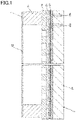
- Fig. 1 is a schematic cross-sectional view illustrating a pellicle according to an embodiment of the present invention mounted on a photomask.
- a photomask 2 on which a pellicle 1 is mounted is a reflective photomask used for EUV lithography.
- the pellicle 1 may be mounted on another type of photomask.
- the photomask 2 includes a substrate 21, a multilayer reflective film 22, a capping film 23, and an absorption layer 24.
- the substrate 21 has a flat front surface.
- the substrate 21 may be made of, for example, synthetic silica having low thermal expansion coefficient.
- the multilayer reflective film 22 is provided on the front surface of the substrate 21.
- the multilayer reflective film 22 includes two or more layers having different refractive indices to EUV light.
- the multilayer reflective film 22 is designed to exhibit high reflectance to EUV light due to interference caused by repeated reflection, and low reflectance to other light.
- the multilayer reflective film 22 includes alternately laminated reflective layers 22a and 22b having different refractive indices to EUV light.
- the reflective layers 22a and 22b one may be made of silicon and the other may be made of molybdenum.
- the multilayer reflective film 22 includes three sets of the reflective layers 22a and 22b in Fig. 1 , usually, it includes a higher number of sets, e.g., about 40 sets.
- the capping film 23 is provided on the multilayer reflective film 22.
- the capping film 23 plays a role of protecting the multilayer reflective film 22 from etching agents or cleaning agents in the process of patterning performed for obtaining the absorption layer 24 or in the process of cleaning the photomask 2.
- the capping film 23 may be made of ruthenium.
- the absorption layer 24 is provided on the capping film 23.
- the absorption layer 24 is provided with openings corresponding to the exposure pattern for the photoresist layer on a semiconductor wafer.
- the absorption layer 24 is a layer made of a material exhibiting high absorptance of EUV light.
- the absorption layer 24 may be made of tantalum, indium oxide, tellurium oxide, or tin telluride.
- the pellicle 1 is mounted on the photomask 2.
- the pellicle 1 herein prevents dust and other materials from adhering to the reflective surface of the photomask 2. It should be noted that, if the photomask is of a transmissive type, the pellicle 1 may be mounted on both surfaces of the photomask.
- the pellicle 1 includes a frame 11 and a pellicle film 12.
- the frame 11 is mounted on the photomask 2 via an adhesive, not shown.
- the frame 11 serves as a spacer for separating the pellicle film 12 from the photomask 2.
- the frame 11 may be made of aluminum.
- the pellicle film 12 is a film having high transmittance to exposure light which is EUV light herein.
- the pellicle film 12 is supported by the frame 11 so as to face the photomask 2 via the frame 11.
- the pellicle film 12 has a periphery which is fixed to the frame 11 using an adhesive, for example.
- the pellicle film 12 is a carbon nanotube film. Specifically, the pellicle film 12 contains a plurality of first carbon nanotubes extending in a first direction and arrayed in their radial direction, and a plurality of second carbon nanotubes extending in a second direction intersecting the first direction, and arrayed in their radial direction. According to an example, the pellicle film 12 may be made of only the first and second carbon nanotubes.
- Fig. 2 is a schematic perspective view illustrating an example of a pellicle film that can be used for the pellicle shown in Fig. 1 .
- the pellicle film 12 shown in Fig. 2 includes a first carbon nanotube web 121a and a second carbon nanotube web 121b.
- the first carbon nanotube web 121a is formed of a plurality of first carbon nanotubes 1200a.
- the first carbon nanotubes 1200a extend in a first direction D1 and are arrayed in their radial direction.
- the second carbon nanotube web 121b is formed of a plurality of second carbon nanotubes 1200b.
- the second carbon nanotubes 1200b extend in a second direction D2 intersecting the first direction D1, and are arrayed in their radial direction.
- the first and second directions D1 and D2 may be orthogonal to each other.
- the first and second directions D1 and D2 may obliquely intersect each other.
- first carbon nanotube web 121a could unavoidably contain carbon nanotubes extending in directions other than the first direction D1, or bent carbon nanotubes.
- second carbon nanotube web 121b could unavoidably contain carbon nanotubes extending in directions other than the second direction D2, or bent carbon nanotubes.
- the first carbon nanotube web 121a is illustrated as if it is a monolayer film in which the first carbon nanotubes 1200a are arrayed only in the in-plane direction without being laminated in the thickness direction; however, the first carbon nanotubes 1200a may be laminated in the thickness direction, while being arrayed in the in-plane direction.
- the second carbon nanotube web 121b is illustrated as if it is a monolayer film in which the second carbon nanotubes 1200b are arrayed only in the in-plane direction without being laminated in the thickness direction; however, the second carbon nanotubes 1200b may be laminated in the thickness direction, while being arrayed in the in-plane direction.
- the carbon nanotubes have the same diameter in the first carbon nanotube web 121a, but they do not necessarily have to have the same diameter.
- the carbon nanotubes have the same diameter in the second carbon nanotube web 121b, but they do not necessarily have to have the same diameter.
- the carbon nanotubes have the same diameter between the first and second carbon nanotube webs 121a and 121b, but they do not necessarily have to have the same diameter between these webs.
- the first carbon nanotube web 121a is in contact with the second carbon nanotube web 121b, but these webs may be separated from each other.
- the first carbon nanotubes 1200a may be in contact with or separated from the second carbon nanotubes 1200b.
- the pellicle film 12 may include three or more carbon nanotube webs.
- the pellicle film 12 may include two or more first carbon nanotube webs 121a and one or more second carbon nanotube webs 121b.
- the pellicle film 12 may include one or more first carbon nanotube webs 121a and two or more second carbon nanotube webs 121b.
- the pellicle film 12 may include one or more first carbon nanotube webs 121a, one or more second carbon nanotube webs 121b, and one or more carbon nanotube webs having a structure similar to the first and second carbon nanotube webs 121a and 121b except for having different length directions.
- the pellicle film 12 is preferred to have a thickness of 500 nm or less. If the pellicle film 12 is thicker, transmittance for exposure light, which is EUV light herein, may be deteriorated. The thickness of the pellicle film 12 is preferred to be 10 nm or more. If the pellicle film 12 is thinner, physical strength thereof may be reduced, and dust and other materials may permeate into the pellicle film 12.
- the pellicle film 12 does not allow permeation of dust and other materials with a diameter of more than 30 nm therethrough.
- the carbon nanotubes in the pellicle film 12 are preferred to have gaps therebetween which do not allow permeation of dust and other materials with a diameter of more than 30 nm therethrough.
- the pellicle film 12 can be prepared through the following method.
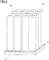
- Fig. 3 is a schematic perspective view illustrating an example of a carbon nanotube array that can be used for preparing the pellicle film shown in Fig. 2 .
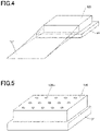
- Fig. 4 is a schematic perspective view illustrating an example of a method of producing a carbon nanotube web.
- the structure shown in Fig. 3 When preparing the pellicle film 12, the structure shown in Fig. 3 is prepared, first.
- the structure shown in Fig. 3 includes a substrate 31, a catalyst layer 32, and a carbon nanotube array 120.
- the substrate 31 has a flat front surface.
- the substrate 31 may be a silicon substrate, glass substrate, or sapphire substrate.
- the catalyst layer 32 is provided on the front surface of the substrate 31.
- the catalyst layer 32 may be made of metal such as iron, nickel or cobalt.
- the underlayer may be made of aluminum nitride, aluminum oxide, or silicon oxide.
- the carbon nanotube array 120 is an aggregation of a number of carbon nanotubes 1200.
- the carbon nanotubes 1200 provided on the surface, as a support surface, of the catalyst layer 32 are substantially perpendicularly extended therefrom. It should be noted that the term carbon nanotube array is a synonym of the term carbon nanotube forest.
- the carbon nanotubes 1200 may be single-wall nanotubes, or may be multiwall nanotubes, or may be a combination thereof. Furthermore, the carbon nanotubes 1200 may be any of armchair tubes, zigzag tubes, chiral tubes, or a combination of two or more of these tubes.
- the carbon nanotubes 1200 may have a length, for example, in the range of 0.1 mm to 5 mm. It should be noted that the ratio between the length and the diameter of the carbon nanotubes 1200 shown in Fig. 3 is much smaller than the actual ratio.
- the carbon nanotube array 120 can be prepared, for example, using chemical vapor deposition (CVD) such as super-growth CVD (water-assisted CVD).
- CVD chemical vapor deposition
- super-growth CVD water-assisted CVD
- the carbon nanotubes 1200 are drawn out in a web shape from an end face of the carbon nanotube array 120.
- the carbon nanotubes 1200 adjacent to each other in the radial direction experience the Van der Waals force. Therefore, for example, when the end face of the carbon nanotube array 120 or a part thereof is held and stretched in a direction away from the carbon nanotube array 120, the carbon nanotubes 1200 can be drawn out from the carbon nanotube array 120 one after another.
- a carbon nanotube web 121 can be obtained without using an adhesive or the like.
- the carbon nanotube web 121 thus obtained is a self-supporting film that can be independently handled. Furthermore, most of the carbon nanotubes 1200 in the carbon nanotube web 121 have a shape extending in the direction in which they are drawn out.
- a plurality of carbon nanotube webs 121 are overlapped with each other so that the length direction of the carbon nanotubes 1200 contained in one web intersects the length direction of the carbon nanotubes 1200 contained in another web. Then, this laminate is pressed.
- the laminate may be pressed in its entirety, or only one or more portions thereof may be pressed. The laminate does not necessarily have to be pressed.
- a carbon nanotube film can be obtained.
- the carbon nanotube film thus obtained can be used as the pellicle film 12 described above.
- the pellicle film 12 has high in-plane transmittance uniformity. This will be described below.
- the carbon nanotube film can also be obtained, for example, by forming a coating film from a dispersion liquid of carbon nanotubes and removing the dispersion medium from the coating film.
- agglomeration of carbon nanotubes may occur in the process of removing the dispersion medium. Therefore, the carbon nanotube films obtained through this method tend to have portions where carbon nanotubes are present at high density and portions where they are present at low density.
- carbon nanotube films obtained through this method include a number of portions where the carbon nanotubes intersect each other. EUV light absorption occurs in the carbon nanotubes intersecting each other. Accordingly, as the number of intersections increases, a larger amount of EUV light is absorbed. Therefore, there may be a difference in the amount of absorbed EUV light between the portions where the carbon nanotubes intersect each other and the portions where they do not intersect each other. These intersections are not necessarily distributed uniformly, but may be distributed non-uniformly.
- carbon nanotube films obtained using a dispersion liquid of carbon nanotubes have insufficient in-plane transmittance uniformity.
- most of the carbon nanotubes 1200 in the carbon nanotube web 121 have a shape extending in the direction in which they are drawn out. In other words, the carbon nanotubes 1200 extend in one direction and are arrayed in their radial direction.
- the carbon nanotubes 1200 are uniformly distributed in the carbon nanotube web 121.
- the carbon nanotube web 121 includes fewer portions where the carbon nanotubes 1200 intersect each other. Therefore, when a plurality of carbon nanotube webs 121 are overlapped with each other so that the length direction of the carbon nanotubes 1200 contained in one web intersects the length direction of the carbon nanotubes 1200 contained in another web, intersections of the carbon nanotubes 1200 can be uniformly distributed.
- the pellicle film 12 has high in-plane transmittance uniformity.
- the pellicle film 12 can be modified in various ways.
- Fig. 5 is a schematic perspective view illustrating a modification of a carbon nanotube array.
- Fig. 6 is a schematic plan view illustrating an example of a carbon nanotube web obtained using the carbon nanotube array shown in Fig. 5 .
- the carbon nanotube array 120 shown in Fig. 5 is similar to the carbon nanotube array 120 described referring to Fig. 3 , except that a plurality of pores or concavities 120H are provided therein.
- the pores or concavities 120H may be through holes.
- the carbon nanotube array 120 having the pores or concavities 120H can be obtained, for example, by having the catalyst layer 32 described referring to Fig. 3 opened at positions corresponding to the pores or concavities 120H.
- the pores or concavities 120H may be blind pores, i.e., concavities provided at the surface of the carbon nanotube array 120 and having bottoms which are formed of ends of the plurality of carbon nanotubes 1200.
- the carbon nanotube array 120 having the pores or concavities 120H can be obtained, for example, by preparing the carbon nanotube array 120 shown in Fig. 4 , and forming a mask layer thereon having openings at positions corresponding to the pores or concavities 120H, followed by etching the carbon nanotubes 1200 inward into the array at the positions of the openings.
- a carbon nanotube array 120 having pores or concavities 120H is thus obtained through the processes described above. Then, except for using this array, a carbon nanotube web 121 is obtained using a method similar to the method described referring to Fig. 4 . Since the carbon nanotube array 120 includes the pores or concavities 120H, the carbon nanotube web 121 obtained in this way includes a plurality of pores 121H as shown in Fig. 6 . The pores 121H are preferred to have a maximum diameter of 100 nm or less.
- the pores 121H can be formed at any positions and with any dimensions by appropriately setting the positions and dimensions of the pores or concavities 120H provided to the carbon nanotube array 120, the speed of drawing out the carbon nanotube web 121, and other parameters. Accordingly, if the carbon nanotube web 121 including the pores 121H is applied to the pellicle film 12, for example, transmittance of the pellicle film 12 can be enhanced without adversely affecting the patterning performed using the photomask 2.
- transmittance that can be achieved is equivalent to the transmittance in the case of using the carbon nanotube web including the pores 121H.
- the thickness of the pellicle film 12 is preferred to be 1,000 nm or less.
- a structure including a laminate of a plurality of carbon nanotube webs has been described so far, but the pellicle film 12 may have other structures.
- Fig. 7 is a schematic plan view illustrating another example of a pellicle film that can be used for the pellicle shown in Fig. 1 .
- Fig. 8 is a schematic diagram illustrating an example a carbon nanotube thread that can be used for the pellicle film shown in Fig. 7 .
- the pellicle film 12 shown in Fig. 7 contains a plurality of first carbon nanotube threads 122a extending in a first direction D1, and a plurality of second carbon nanotube threads 122b extending in a second direction D2 intersecting the first direction D1.
- the first and second carbon nanotube threads 122a and 122b form a woven textile.
- the woven textile may have a plain weave, twill weave, or satin weave.
- Each thread of the first and second carbon nanotube threads 122a and 122b has a structure, for example, similar to the carbon nanotube thread 122 shown in Fig. 8 .
- the carbon nanotube thread 122 shown in Fig. 8 includes a plurality of carbon nanotubes 1200 extending in the length direction of the carbon nanotube thread 122.
- This pellicle film 12 is preferred to have a thickness of 500 nm or less. If the pellicle film 12 is thicker, transmittance for exposure light, which is EUV light herein, may be deteriorated. The thickness of this pellicle film 12 is preferred to be 10 nm or more. If the pellicle film 12 is thinner, physical strength thereof may be reduced, and dust and other materials may permeate into the pellicle film 12.
- Each thread of the first and second carbon nanotube threads 122a and 122b is preferred to have a diameter of 100 nm or less. If the diameter is larger, the pellicle film 12 may have a larger thickness. Each thread of the first and second carbon nanotube threads 122a and 122b is preferred to have a diameter of 1 nm or more. If the diameter is smaller, physical strength thereof may be reduced, and productivity of the woven textile may be reduced.
- the pellicle film 12 does not allow permeation of dust and other materials with a diameter of more than 30 nm therethrough.
- the maximum distance between the adjacent threads is preferred to be 100 nm or less. Even if the maximum length between the adjacent threads in the first and second carbon nanotube threads 122a and 122b is 100 nm, dust and other materials with a diameter of 30 nm could permeate through the threads.
- a plurality of carbon nanotube layers each having a structure similar to that of the pellicle film 12 described referring to Fig. 7 are overlapped with each other for use as a pellicle film, dust and other materials can be prevented from permeating therethrough.
- this pellicle film 12 can be prepared using the following method.
- Fig. 9 is a schematic perspective view illustrating an example of a method of producing a carbon nanotube thread.
- a carbon nanotube array 120 shown in Fig. 9 is prepared using a method similar to the method described referring to Fig. 3 .
- the carbon nanotubes 1200 are drawn out in a thread shape from an end face of the carbon nanotube array 120.
- the carbon nanotubes 1200 adjacent to each other in the radial direction experience the Van der Waals force. Therefore, for example, when the end face of the carbon nanotube array 120 or a part thereof is held and stretched in a direction away from the carbon nanotube array 120, the carbon nanotubes 1200 can be drawn out from the carbon nanotube array 120 one after another.
- a carbon nanotube thread 122 can be obtained without using an adhesive or the like.
- the carbon nanotube thread 122 may be twisted, or may not be twisted as shown in Fig. 8 . If not twisted, most of the carbon nanotubes 1200 in the carbon nanotube thread 122 will have a shape extending in the direction in which they are drawn out.
- a woven textile is formed using the carbon nanotube threads 122. Then, the woven textile is pressed.
- the woven textile may be pressed in its entirety, or only one or more portions thereof may be pressed.
- the laminate does not necessarily have to be pressed.
- a carbon nanotube film can be obtained.
- the carbon nanotube film thus obtained can be used as the pellicle film 12 described above.
- the first and second carbon nanotube threads 122a and 122b are formed of the carbon nanotubes 1200, and the woven textile is formed of the threads.
- the diameter of each thread of the first and second carbon nanotube threads 122a and 122b can be controlled with high accuracy, and placement of the first and second carbon nanotubes 122a and 122b can also be controlled with high accuracy. Therefore, the carbon nanotubes 1200 and the intersections thereof can be uniformly distributed. Accordingly, this pellicle film 12 also has high in-plane transmittance uniformity.
- This pellicle film 12 can be modified in various ways.
- Fig. 10 is a schematic diagram illustrating a carbon nanotube thread according to a modification.
- the carbon nanotube thread 122 described referring to Fig. 8 has a substantially constant diameter in the length direction.
- the carbon nanotube thread 122 shown in Fig. 10 has a diameter varying along the length direction.
- the carbon nanotube thread 122 shown in Fig. 10 is similar to the carbon nanotube thread 122 described referring to Fig. 8 .
- This carbon nanotube 122 can be prepared, for example, using a method similar to the method described referring to Fig. 9 , except that the carbon nanotube array 120 described referring to Fig. 5 is used.
- the maximum and minimum diameters of the carbon nanotube thread 122, the pitch thereof, and the like can be controlled by appropriately setting the positions and dimensions of the pores or concavities 120H, the speed of drawing out the carbon nanotube web 121, and other parameters. Furthermore, the positions of large-diameter portions or small-diameter portions of the carbon nanotube thread 122 in the woven textile can also be controlled with high accuracy. Accordingly, if the carbon nanotube thread 122 is used for the pellicle film 12, for example, transmittance of the pellicle film 12 and in-plane transmittance uniformity can be controlled.
- the pellicle film 12 may further contain carbon nanotubes, carbon nanotube threads, carbon nanotube webs, woven textiles formed of carbon nanotube threads, and a covering layer made of two or more of these materials. Provision of a covering layer can contribute to further reducing permeation of dust and other materials.
- the pellicle film 12 described referring to Fig. 2 may further include one or more covering layers covering at least one of the first and second carbon nanotube webs 121a and 121b.
- the covering layers may be provided to at least one of first and second carbon nanotube webs 121a and 121b before these webs are overlapped with each other.
- the covering layers may be provided to at least one of first and second carbon nanotube webs 121a and 121b, after these webs are overlapped with each other.
- provision of the covering layers can easily maintain a balance between achieving high transmittance and reducing permeation of dust and other materials.
- the pellicle film 12 described referring to Fig. 4 may further include one or more covering layers covering at least either of the first carbon nanotube threads 122a and the second carbon nanotube threads 122b, and may further include one or more covering layers covering the woven textile formed of the first and second carbon nanotube threads 122a and 122b.
- the covering layers may be provided to at least either of the first carbon nanotube threads 122a and the second carbon nanotube threads 122b before forming the woven textile. In both of the cases, achieving high transmittance can be easily balanced with reducing permeation of dust and other materials.
- the covering layer may be made of metal or semiconductor.
- the covering layer may contain one or more elements selected from the group consisting of silicon, molybdenum, ruthenium, boron, nitrogen, germanium, and hafnium.
- the covering layer may contain boron, boron carbide, zirconium nitride, molybdenum, ruthenium, silicon carbide, titanium nitride, amorphous carbon, graphene, or a combination of two or more thereof.
- carbon nanotube webs may be used in applications other than pellicles.
Landscapes
- Chemical & Material Sciences (AREA)
- Engineering & Computer Science (AREA)
- Materials Engineering (AREA)
- Nanotechnology (AREA)
- Organic Chemistry (AREA)
- Physics & Mathematics (AREA)
- General Physics & Mathematics (AREA)
- Inorganic Chemistry (AREA)
- Preparing Plates And Mask In Photomechanical Process (AREA)
- Carbon And Carbon Compounds (AREA)
Abstract
Description
- The present invention relates to pellicles.
- Patterns with a minimum dimension that can be formed using photolithography depend on the wavelength of the light used for exposure. This minimum dimension can be reduced using shorter wavelength light for exposure.
- In the past, ArF excimer laser light having a wavelength of 193 nm has been used for exposure. In recent years, there has been an increasing demand for photolithography capable of forming finer patterns, in response to which, use of extreme ultraviolet (EUV light) having a wavelength of 13.5 nm is becoming a trend.
- Pellicles are used for preventing dust and other materials from adhering to photomasks or reticles. Since EUV light is easily absorbed into various substances, pellicle films made of poly silicon, which has low absorptance of EUV light, are under development in extreme ultraviolet lithography (EUVL).
- However, pellicle films made of polysilicon are inferior in heat resistance. In this regard, pellicle films made of carbon materials, such as graphene or carbon nanotubes, are receiving attention (see PTLs 1 to 3).
-
- PTL 1:
JP 2018-194838 A - PTL 2:
JP 2018-194840 A - PTL 3:
WO2018/008594 - Pellicle films containing carbon nanotubes may have insufficient in-plane transmittance uniformity due to the carbon nanotubes being non-uniformly distributed.
- The present invention aims to provide a technique that can achieve a pellicle film made of carbon nanotubes and having high in-plane transmittance uniformity.
- According to a first aspect of the present invention, there is provided a pellicle film containing a plurality of first carbon nanotubes each extending in a first direction and arrayed in a radial direction, and a plurality of second carbon nanotubes each extending in a second direction intersecting the first direction, and arrayed in a radial direction.
- According to another aspect of the present invention, there is provided a pellicle film according to the first aspect, in which the plurality of first carbon nanotubes form a first carbon nanotube web, and the plurality of second carbon nanotubes form a second carbon nanotube web overlapped with the first carbon nanotube web.
- According to still another aspect of the present invention, there is provided a pellicle film according to the above aspect, in which at least one of the first carbon nanotube web and the second carbon nanotube web is provided with a plurality of pores.
- According to still another aspect of the present invention, there is provided a pellicle film according to the above aspect, further including one or more covering layers covering at least one of the first carbon nanotube web and the second carbon nanotube web, the at least one of the first carbon nanotube web and the second carbon nanotube web being provided with the plurality of pores.
- According to still another aspect of the present invention, there is provided a pellicle film according to any of the above aspects, in which the plurality of pores have a maximum diameter of 100 nm or less.
- According to still another aspect of the present invention, there is provided a pellicle film according to the first aspect, in which the plurality of first carbon nanotubes form a plurality of first carbon nanotube threads each being formed of a plurality of carbon nanotubes, the plurality of second carbon nanotubes form a plurality of second carbon nanotube threads each being formed of a plurality of carbon nanotubes, and the plurality of first carbon nanotube threads and the plurality of second carbon nanotube threads form a woven textile.
- According a second aspect of the present invention, there is provided a pellicle film containing a plurality of first carbon nanotube threads each being formed of a plurality of first carbon nanotubes and extending in a first direction; and a plurality of second carbon nanotube threads each being formed of a plurality of second carbon nanotubes and extending in a second direction intersecting the first direction, in which the plurality of first carbon nanotube threads and the plurality of second carbon nanotube threads form a woven textile.
- According to still another aspect of the present invention, there is provided a pellicle film according to any of the above aspects, in which a maximum distance among distances between adjacent carbon nanotube threads in the plurality of first carbon nanotube threads, and among distances between adjacent carbon nanotube threads in the plurality of second carbon nanotube threads is 100 nm or less.
- According to still another aspect of the present invention, there is provided a pellicle film according to the any of the above aspects, in which one or more carbon nanotube threads, in the plurality of first carbon nanotube threads and the plurality of second carbon nanotube threads, each have a diameter varying along a length direction.
- According to still another aspect of the present invention, there is provided a pellicle film according to any of the above aspects, in which the pellicle film has a thickness of 500 nm or less.
- According to a third aspect of the present invention, there is provided a pellicle including the pellicle film according to any of the above aspects; and a frame supporting the pellicle film.
- According to a fourth aspect of the present invention, there is provided a carbon nanotube web containing a plurality of carbon nanotubes each extending in one direction and arrayed in a radial direction, in which the carbon nanotube web is provided with a plurality of pores.
- According a fifth aspect of the present invention, there is provided a carbon nanotube film including a first carbon nanotube web including a plurality of first carbon nanotubes each extending in a first direction and arrayed in a radial direction; and a second carbon nanotube web including a plurality of second carbon nanotubes each extending in a second direction intersecting the first direction, and arrayed in a radial direction, in which at least one of the first carbon nanotube web and the second carbon nanotube web is provided with a plurality of pores.
- According a sixth aspect of the present invention, there is provided a carbon nanotube thread containing a plurality of carbon nanotubes, in which the carbon nanotube thread has a diameter varying along a length direction.
- According a seventh aspect of the present invention, there is provided a method of producing a carbon nanotube web, including preparing a carbon nanotube array formed of a plurality of carbon nanotubes extending from a support surface, the carbon nanotube array including one or more pores or concavities; and drawing out the carbon nanotubes in a web shape from an end face of the carbon nanotube array.
- According an eighth aspect of the present invention, there is provided a method of producing a carbon nanotube thread, including preparing a carbon nanotube array formed of a plurality of carbon nanotubes extending from a support surface, the carbon nanotube array including one or more pores or concavities; and drawing out the carbon nanotubes in a thread shape from an end face of the carbon nanotube array.
- According to the present invention, there is provided a technique that can achieve a pellicle film made of carbon nanotubes and having high in-plane transmittance uniformity.
-
-
Fig. 1 is a schematic cross-sectional view illustrating a pellicle according to an embodiment of the present invention mounted on a photomask. -
Fig. 2 is a schematic perspective view illustrating an example of a pellicle film that can be used for the pellicle shown inFig. 1 . -
Fig. 3 is a schematic perspective view illustrating an example of a carbon nanotube array that can be used for preparing the pellicle film shown inFig. 2 . -
Fig. 4 is a schematic perspective view illustrating an example of a method of producing a carbon nanotube web. -
Fig. 5 is a schematic perspective view illustrating a modification of a carbon nanotube array. -
Fig. 6 is a schematic plan view illustrating an example of a carbon nanotube web obtained using the carbon nanotube array shown inFig. 5 . -
Fig. 7 is a schematic plan view illustrating another example of a pellicle film that can be used for the pellicle shown inFig. 1 . -
Fig. 8 is a schematic diagram illustrating an example a carbon nanotube thread that can be used for the pellicle film shown inFig. 7 . -
Fig. 9 is a schematic perspective view illustrating an example of a method of producing a carbon nanotube thread. -
Fig. 10 is a schematic diagram illustrating a carbon nanotube thread according to a modification. - Referring to the drawings, some embodiments of the present invention will be described. The embodiment described below is a specific version of any of the aspects set forth above. It should be noted that, in the drawings referred to below, components having like functions are designated with like reference signs to omit repeated explanation. Furthermore, in each of the drawings, the dimensional ratio or the shape is not necessarily to scale.
-
Fig. 1 is a schematic cross-sectional view illustrating a pellicle according to an embodiment of the present invention mounted on a photomask. - In
Fig. 1 , aphotomask 2 on which a pellicle 1 is mounted is a reflective photomask used for EUV lithography. The pellicle 1 may be mounted on another type of photomask. - The
photomask 2 includes asubstrate 21, a multilayerreflective film 22, acapping film 23, and anabsorption layer 24. - The
substrate 21 has a flat front surface. Thesubstrate 21 may be made of, for example, synthetic silica having low thermal expansion coefficient. - The multilayer
reflective film 22 is provided on the front surface of thesubstrate 21. The multilayerreflective film 22 includes two or more layers having different refractive indices to EUV light. The multilayerreflective film 22 is designed to exhibit high reflectance to EUV light due to interference caused by repeated reflection, and low reflectance to other light. - Herein, the multilayer
reflective film 22 includes alternately laminatedreflective layers reflective layers reflective film 22 includes three sets of thereflective layers Fig. 1 , usually, it includes a higher number of sets, e.g., about 40 sets. - The
capping film 23 is provided on the multilayerreflective film 22. Thecapping film 23 plays a role of protecting the multilayerreflective film 22 from etching agents or cleaning agents in the process of patterning performed for obtaining theabsorption layer 24 or in the process of cleaning thephotomask 2. For example, the cappingfilm 23 may be made of ruthenium. - The
absorption layer 24 is provided on thecapping film 23. Theabsorption layer 24 is provided with openings corresponding to the exposure pattern for the photoresist layer on a semiconductor wafer. - The
absorption layer 24 is a layer made of a material exhibiting high absorptance of EUV light. For example, theabsorption layer 24 may be made of tantalum, indium oxide, tellurium oxide, or tin telluride. - The pellicle 1 is mounted on the
photomask 2. The pellicle 1 herein prevents dust and other materials from adhering to the reflective surface of thephotomask 2. It should be noted that, if the photomask is of a transmissive type, the pellicle 1 may be mounted on both surfaces of the photomask. - The pellicle 1 includes a
frame 11 and apellicle film 12. - The
frame 11 is mounted on thephotomask 2 via an adhesive, not shown. Theframe 11 serves as a spacer for separating thepellicle film 12 from thephotomask 2. For example, theframe 11 may be made of aluminum. - The
pellicle film 12 is a film having high transmittance to exposure light which is EUV light herein. Thepellicle film 12 is supported by theframe 11 so as to face thephotomask 2 via theframe 11. Specifically, thepellicle film 12 has a periphery which is fixed to theframe 11 using an adhesive, for example. - The
pellicle film 12 is a carbon nanotube film. Specifically, thepellicle film 12 contains a plurality of first carbon nanotubes extending in a first direction and arrayed in their radial direction, and a plurality of second carbon nanotubes extending in a second direction intersecting the first direction, and arrayed in their radial direction. According to an example, thepellicle film 12 may be made of only the first and second carbon nanotubes. -
Fig. 2 is a schematic perspective view illustrating an example of a pellicle film that can be used for the pellicle shown inFig. 1 . - The
pellicle film 12 shown inFig. 2 includes a firstcarbon nanotube web 121a and a secondcarbon nanotube web 121b. The first and secondcarbon nanotube webs - The first
carbon nanotube web 121a is formed of a plurality offirst carbon nanotubes 1200a. Thefirst carbon nanotubes 1200a extend in a first direction D1 and are arrayed in their radial direction. - The second
carbon nanotube web 121b is formed of a plurality ofsecond carbon nanotubes 1200b. Thesecond carbon nanotubes 1200b extend in a second direction D2 intersecting the first direction D1, and are arrayed in their radial direction. According to an example, the first and second directions D1 and D2 may be orthogonal to each other. The first and second directions D1 and D2 may obliquely intersect each other. - It should be noted that the first
carbon nanotube web 121a could unavoidably contain carbon nanotubes extending in directions other than the first direction D1, or bent carbon nanotubes. Similarly, the secondcarbon nanotube web 121b could unavoidably contain carbon nanotubes extending in directions other than the second direction D2, or bent carbon nanotubes. - In
Fig. 2 , the firstcarbon nanotube web 121a is illustrated as if it is a monolayer film in which thefirst carbon nanotubes 1200a are arrayed only in the in-plane direction without being laminated in the thickness direction; however, thefirst carbon nanotubes 1200a may be laminated in the thickness direction, while being arrayed in the in-plane direction. Similarly, inFig. 2 , the secondcarbon nanotube web 121b is illustrated as if it is a monolayer film in which thesecond carbon nanotubes 1200b are arrayed only in the in-plane direction without being laminated in the thickness direction; however, thesecond carbon nanotubes 1200b may be laminated in the thickness direction, while being arrayed in the in-plane direction. - In
Fig. 2 , the carbon nanotubes have the same diameter in the firstcarbon nanotube web 121a, but they do not necessarily have to have the same diameter. Similarly, inFig. 2 , the carbon nanotubes have the same diameter in the secondcarbon nanotube web 121b, but they do not necessarily have to have the same diameter. Also, inFig. 2 , the carbon nanotubes have the same diameter between the first and secondcarbon nanotube webs - Also, in
Fig. 2 , the firstcarbon nanotube web 121a is in contact with the secondcarbon nanotube web 121b, but these webs may be separated from each other. In other words, thefirst carbon nanotubes 1200a may be in contact with or separated from thesecond carbon nanotubes 1200b. - The
pellicle film 12 may include three or more carbon nanotube webs. In this case, thepellicle film 12 may include two or more firstcarbon nanotube webs 121a and one or more secondcarbon nanotube webs 121b. Alternatively, thepellicle film 12 may include one or more firstcarbon nanotube webs 121a and two or more secondcarbon nanotube webs 121b. Alternatively, thepellicle film 12 may include one or more firstcarbon nanotube webs 121a, one or more secondcarbon nanotube webs 121b, and one or more carbon nanotube webs having a structure similar to the first and secondcarbon nanotube webs - The
pellicle film 12 is preferred to have a thickness of 500 nm or less. If thepellicle film 12 is thicker, transmittance for exposure light, which is EUV light herein, may be deteriorated. The thickness of thepellicle film 12 is preferred to be 10 nm or more. If thepellicle film 12 is thinner, physical strength thereof may be reduced, and dust and other materials may permeate into thepellicle film 12. - It is preferred that the
pellicle film 12 does not allow permeation of dust and other materials with a diameter of more than 30 nm therethrough. In other words, the carbon nanotubes in thepellicle film 12 are preferred to have gaps therebetween which do not allow permeation of dust and other materials with a diameter of more than 30 nm therethrough. - For example, the
pellicle film 12 can be prepared through the following method. -
Fig. 3 is a schematic perspective view illustrating an example of a carbon nanotube array that can be used for preparing the pellicle film shown inFig. 2 .Fig. 4 is a schematic perspective view illustrating an example of a method of producing a carbon nanotube web. - When preparing the
pellicle film 12, the structure shown inFig. 3 is prepared, first. The structure shown inFig. 3 includes asubstrate 31, a catalyst layer 32, and acarbon nanotube array 120. - The
substrate 31 has a flat front surface. For example, thesubstrate 31 may be a silicon substrate, glass substrate, or sapphire substrate. - The catalyst layer 32 is provided on the front surface of the
substrate 31. For example, the catalyst layer 32 may be made of metal such as iron, nickel or cobalt. - There may be provided an underlayer between the
substrate 31 and the catalyst layer 32. For example, the underlayer may be made of aluminum nitride, aluminum oxide, or silicon oxide. - The
carbon nanotube array 120 is an aggregation of a number ofcarbon nanotubes 1200. Thecarbon nanotubes 1200 provided on the surface, as a support surface, of the catalyst layer 32 are substantially perpendicularly extended therefrom. It should be noted that the term carbon nanotube array is a synonym of the term carbon nanotube forest. - The
carbon nanotubes 1200 may be single-wall nanotubes, or may be multiwall nanotubes, or may be a combination thereof. Furthermore, thecarbon nanotubes 1200 may be any of armchair tubes, zigzag tubes, chiral tubes, or a combination of two or more of these tubes. - The
carbon nanotubes 1200 may have a length, for example, in the range of 0.1 mm to 5 mm. It should be noted that the ratio between the length and the diameter of thecarbon nanotubes 1200 shown inFig. 3 is much smaller than the actual ratio. - The
carbon nanotube array 120 can be prepared, for example, using chemical vapor deposition (CVD) such as super-growth CVD (water-assisted CVD). - Next, as shown in
Fig. 4 , thecarbon nanotubes 1200 are drawn out in a web shape from an end face of thecarbon nanotube array 120. Thecarbon nanotubes 1200 adjacent to each other in the radial direction experience the Van der Waals force. Therefore, for example, when the end face of thecarbon nanotube array 120 or a part thereof is held and stretched in a direction away from thecarbon nanotube array 120, thecarbon nanotubes 1200 can be drawn out from thecarbon nanotube array 120 one after another. Thus, acarbon nanotube web 121 can be obtained without using an adhesive or the like. - The
carbon nanotube web 121 thus obtained is a self-supporting film that can be independently handled. Furthermore, most of thecarbon nanotubes 1200 in thecarbon nanotube web 121 have a shape extending in the direction in which they are drawn out. - Then, a plurality of
carbon nanotube webs 121 are overlapped with each other so that the length direction of thecarbon nanotubes 1200 contained in one web intersects the length direction of thecarbon nanotubes 1200 contained in another web. Then, this laminate is pressed. The laminate may be pressed in its entirety, or only one or more portions thereof may be pressed. The laminate does not necessarily have to be pressed. - Through the process described above, a carbon nanotube film can be obtained. The carbon nanotube film thus obtained can be used as the
pellicle film 12 described above. - The
pellicle film 12 has high in-plane transmittance uniformity. This will be described below. - The carbon nanotube film can also be obtained, for example, by forming a coating film from a dispersion liquid of carbon nanotubes and removing the dispersion medium from the coating film. However, according to such a method, agglomeration of carbon nanotubes may occur in the process of removing the dispersion medium. Therefore, the carbon nanotube films obtained through this method tend to have portions where carbon nanotubes are present at high density and portions where they are present at low density.
- Furthermore, most of the carbon nanotubes are curved and/or bent in carbon nanotube films obtained using a dispersion liquid of carbon nanotubes. Therefore, carbon nanotube films obtained through this method include a number of portions where the carbon nanotubes intersect each other. EUV light absorption occurs in the carbon nanotubes intersecting each other. Accordingly, as the number of intersections increases, a larger amount of EUV light is absorbed. Therefore, there may be a difference in the amount of absorbed EUV light between the portions where the carbon nanotubes intersect each other and the portions where they do not intersect each other. These intersections are not necessarily distributed uniformly, but may be distributed non-uniformly.
- Accordingly, carbon nanotube films obtained using a dispersion liquid of carbon nanotubes have insufficient in-plane transmittance uniformity.
- In contrast, most of the
carbon nanotubes 1200 in thecarbon nanotube web 121 have a shape extending in the direction in which they are drawn out. In other words, thecarbon nanotubes 1200 extend in one direction and are arrayed in their radial direction. - Such a structure cannot be obtained using a dispersion liquid of carbon nanotubes, but can be obtained using the method described referring to
Fig. 4 . Therefore, thecarbon nanotubes 1200 are uniformly distributed in thecarbon nanotube web 121. Also, thecarbon nanotube web 121 includes fewer portions where thecarbon nanotubes 1200 intersect each other. Therefore, when a plurality ofcarbon nanotube webs 121 are overlapped with each other so that the length direction of thecarbon nanotubes 1200 contained in one web intersects the length direction of thecarbon nanotubes 1200 contained in another web, intersections of thecarbon nanotubes 1200 can be uniformly distributed. - Accordingly, the
pellicle film 12 has high in-plane transmittance uniformity. - The
pellicle film 12 can be modified in various ways. -
Fig. 5 is a schematic perspective view illustrating a modification of a carbon nanotube array.Fig. 6 is a schematic plan view illustrating an example of a carbon nanotube web obtained using the carbon nanotube array shown inFig. 5 . - The
carbon nanotube array 120 shown inFig. 5 is similar to thecarbon nanotube array 120 described referring toFig. 3 , except that a plurality of pores orconcavities 120H are provided therein. - For example, the pores or
concavities 120H may be through holes. In this case, thecarbon nanotube array 120 having the pores orconcavities 120H can be obtained, for example, by having the catalyst layer 32 described referring toFig. 3 opened at positions corresponding to the pores orconcavities 120H. - Alternatively, the pores or
concavities 120H may be blind pores, i.e., concavities provided at the surface of thecarbon nanotube array 120 and having bottoms which are formed of ends of the plurality ofcarbon nanotubes 1200. In this case, thecarbon nanotube array 120 having the pores orconcavities 120H can be obtained, for example, by preparing thecarbon nanotube array 120 shown inFig. 4 , and forming a mask layer thereon having openings at positions corresponding to the pores orconcavities 120H, followed by etching thecarbon nanotubes 1200 inward into the array at the positions of the openings. - A
carbon nanotube array 120 having pores orconcavities 120H is thus obtained through the processes described above. Then, except for using this array, acarbon nanotube web 121 is obtained using a method similar to the method described referring toFig. 4 . Since thecarbon nanotube array 120 includes the pores orconcavities 120H, thecarbon nanotube web 121 obtained in this way includes a plurality ofpores 121H as shown inFig. 6 . Thepores 121H are preferred to have a maximum diameter of 100 nm or less. - The
pores 121H can be formed at any positions and with any dimensions by appropriately setting the positions and dimensions of the pores orconcavities 120H provided to thecarbon nanotube array 120, the speed of drawing out thecarbon nanotube web 121, and other parameters. Accordingly, if thecarbon nanotube web 121 including thepores 121H is applied to thepellicle film 12, for example, transmittance of thepellicle film 12 can be enhanced without adversely affecting the patterning performed using thephotomask 2. - In the case of using the
carbon nanotube web 121 including thepores 121H in thepellicle film 12, with the thickness of thepellicle film 12 increased, transmittance that can be achieved is equivalent to the transmittance in the case of using the carbon nanotube web including thepores 121H. In the case of using thecarbon nanotube web 121 including thepores 121H in thepellicle film 12, the thickness of thepellicle film 12 is preferred to be 1,000 nm or less. - A structure including a laminate of a plurality of carbon nanotube webs has been described so far, but the
pellicle film 12 may have other structures. -
Fig. 7 is a schematic plan view illustrating another example of a pellicle film that can be used for the pellicle shown inFig. 1 .Fig. 8 is a schematic diagram illustrating an example a carbon nanotube thread that can be used for the pellicle film shown inFig. 7 . - The
pellicle film 12 shown inFig. 7 contains a plurality of firstcarbon nanotube threads 122a extending in a first direction D1, and a plurality of secondcarbon nanotube threads 122b extending in a second direction D2 intersecting the first direction D1. The first and secondcarbon nanotube threads - Each thread of the first and second
carbon nanotube threads carbon nanotube thread 122 shown inFig. 8 . Thecarbon nanotube thread 122 shown inFig. 8 includes a plurality ofcarbon nanotubes 1200 extending in the length direction of thecarbon nanotube thread 122. - This
pellicle film 12 is preferred to have a thickness of 500 nm or less. If thepellicle film 12 is thicker, transmittance for exposure light, which is EUV light herein, may be deteriorated. The thickness of thispellicle film 12 is preferred to be 10 nm or more. If thepellicle film 12 is thinner, physical strength thereof may be reduced, and dust and other materials may permeate into thepellicle film 12. - Each thread of the first and second
carbon nanotube threads pellicle film 12 may have a larger thickness. Each thread of the first and secondcarbon nanotube threads - It is preferred that the
pellicle film 12 does not allow permeation of dust and other materials with a diameter of more than 30 nm therethrough. In other words, in the first and secondcarbon nanotube threads carbon nanotube threads pellicle film 12 described referring toFig. 7 are overlapped with each other for use as a pellicle film, dust and other materials can be prevented from permeating therethrough. - For example, this
pellicle film 12 can be prepared using the following method. -
Fig. 9 is a schematic perspective view illustrating an example of a method of producing a carbon nanotube thread. First, acarbon nanotube array 120 shown inFig. 9 is prepared using a method similar to the method described referring toFig. 3 . - Next, as shown in
Fig. 9 , thecarbon nanotubes 1200 are drawn out in a thread shape from an end face of thecarbon nanotube array 120. Thecarbon nanotubes 1200 adjacent to each other in the radial direction experience the Van der Waals force. Therefore, for example, when the end face of thecarbon nanotube array 120 or a part thereof is held and stretched in a direction away from thecarbon nanotube array 120, thecarbon nanotubes 1200 can be drawn out from thecarbon nanotube array 120 one after another. Thus, acarbon nanotube thread 122 can be obtained without using an adhesive or the like. - It should be noted that the
carbon nanotube thread 122 may be twisted, or may not be twisted as shown inFig. 8 . If not twisted, most of thecarbon nanotubes 1200 in thecarbon nanotube thread 122 will have a shape extending in the direction in which they are drawn out. - After that, a woven textile is formed using the
carbon nanotube threads 122. Then, the woven textile is pressed. The woven textile may be pressed in its entirety, or only one or more portions thereof may be pressed. The laminate does not necessarily have to be pressed. - Through the process described above, a carbon nanotube film can be obtained. The carbon nanotube film thus obtained can be used as the
pellicle film 12 described above. - In this
carbon nanotube web 121, the first and secondcarbon nanotube threads carbon nanotubes 1200, and the woven textile is formed of the threads. The diameter of each thread of the first and secondcarbon nanotube threads second carbon nanotubes carbon nanotubes 1200 and the intersections thereof can be uniformly distributed. Accordingly, thispellicle film 12 also has high in-plane transmittance uniformity. - This
pellicle film 12 can be modified in various ways. -
Fig. 10 is a schematic diagram illustrating a carbon nanotube thread according to a modification. - The
carbon nanotube thread 122 described referring toFig. 8 has a substantially constant diameter in the length direction. In contrast, thecarbon nanotube thread 122 shown inFig. 10 has a diameter varying along the length direction. Except for this, thecarbon nanotube thread 122 shown inFig. 10 is similar to thecarbon nanotube thread 122 described referring toFig. 8 . Thiscarbon nanotube 122 can be prepared, for example, using a method similar to the method described referring toFig. 9 , except that thecarbon nanotube array 120 described referring toFig. 5 is used. - The maximum and minimum diameters of the
carbon nanotube thread 122, the pitch thereof, and the like can be controlled by appropriately setting the positions and dimensions of the pores orconcavities 120H, the speed of drawing out thecarbon nanotube web 121, and other parameters. Furthermore, the positions of large-diameter portions or small-diameter portions of thecarbon nanotube thread 122 in the woven textile can also be controlled with high accuracy. Accordingly, if thecarbon nanotube thread 122 is used for thepellicle film 12, for example, transmittance of thepellicle film 12 and in-plane transmittance uniformity can be controlled. - The
pellicle film 12 may further contain carbon nanotubes, carbon nanotube threads, carbon nanotube webs, woven textiles formed of carbon nanotube threads, and a covering layer made of two or more of these materials. Provision of a covering layer can contribute to further reducing permeation of dust and other materials. - For example, the
pellicle film 12 described referring toFig. 2 may further include one or more covering layers covering at least one of the first and secondcarbon nanotube webs carbon nanotube webs carbon nanotube webs Fig. 6 , if thecarbon nanotube web 121 including thepores 121H is used for thepellicle film 12, provision of the covering layers can easily maintain a balance between achieving high transmittance and reducing permeation of dust and other materials. - Alternatively, the
pellicle film 12 described referring toFig. 4 may further include one or more covering layers covering at least either of the firstcarbon nanotube threads 122a and the secondcarbon nanotube threads 122b, and may further include one or more covering layers covering the woven textile formed of the first and secondcarbon nanotube threads carbon nanotube threads 122a and the secondcarbon nanotube threads 122b before forming the woven textile. In both of the cases, achieving high transmittance can be easily balanced with reducing permeation of dust and other materials. - For example, the covering layer may be made of metal or semiconductor. According to an example, the covering layer may contain one or more elements selected from the group consisting of silicon, molybdenum, ruthenium, boron, nitrogen, germanium, and hafnium. According to another example, the covering layer may contain boron, boron carbide, zirconium nitride, molybdenum, ruthenium, silicon carbide, titanium nitride, amorphous carbon, graphene, or a combination of two or more thereof.
- It should be noted that the carbon nanotube webs, the carbon nanotube threads, and the carbon nanotube films may be used in applications other than pellicles.
-
- 1
- Pellicle
- 2
- Photomask
- 11
- Frame
- 12
- Pellicle film
- 21
- Substrate
- 22
- Multilayer reflective film
- 22a
- Reflective layer
- 22b
- Reflective layer
- 23
- Capping film
- 24
- Absorption layer
- 31
- Substrate
- 32
- Catalyst layer
- 120
- Carbon nanotube array
- 120H
- Pore or concavity
- 121
- Carbon nanotube web
- 121a
- First carbon nanotube web
- 121b
- Second carbon nanotube web
- 121H
- Pore
- 122
- Carbon nanotube thread
- 122a
- First carbon nanotube thread
- 122b
- Second carbon nanotube thread
- 1200
- Carbon nanotube
- 1200a
- First carbon nanotube
- 1200b
- Second carbon nanotube
- D1
- First direction
- D2
- Second direction
Claims (16)
- A pellicle film comprisinga plurality of first carbon nanotubes each extending in a first direction and arrayed in a radial direction; anda plurality of second carbon nanotubes each extending in a second direction intersecting the first direction, and arrayed in a radial direction.
- The pellicle film according to claim 1, wherein the plurality of first carbon nanotubes form a first carbon nanotube web, and the plurality of second carbon nanotubes form a second carbon nanotube web overlapped with the first carbon nanotube web.
- The pellicle film according to claim 2, wherein at least one of the first carbon nanotube web and the second carbon nanotube web is provided with a plurality of pores.
- The pellicle film according to claim 3, further comprising one or more covering layers covering at least one of the first carbon nanotube web and the second carbon nanotube web, the at least one of the first carbon nanotube web and the second carbon nanotube web being provided with the plurality of pores.
- The pellicle film according to claim 3 or 4, wherein the plurality of pores have a maximum diameter of 100 nm or less.
- The pellicle film according to claim 1, wherein the plurality of first carbon nanotubes form a plurality of first carbon nanotube threads each being formed of a plurality of carbon nanotubes, the plurality of second carbon nanotubes form a plurality of second carbon nanotube threads each being formed of a plurality of carbon nanotubes, and the plurality of first carbon nanotube threads and the plurality of second carbon nanotube threads form a woven textile.
- A pellicle film comprisinga plurality of first carbon nanotube threads each being formed of a plurality of first carbon nanotubes and extending in a first direction; anda plurality of second carbon nanotube threads each being formed of a plurality of second carbon nanotubes and extending in a second direction intersecting the first direction, whereinthe plurality of first carbon nanotube threads and the plurality of second carbon nanotube threads form a woven textile.
- The pellicle film according to claim 6 or 7, wherein a maximum distance among distances between adjacent carbon nanotube threads in the plurality of first carbon nanotube threads, and among distances between adjacent carbon nanotube threads in the plurality of second carbon nanotube threads is 100 nm or less.
- The pellicle film according to any one of claims 6 to 8, wherein one or more carbon nanotube threads, in the plurality of first carbon nanotube threads and the plurality of second carbon nanotube threads, each have a diameter varying along a length direction.
- The pellicle film according to any one of claims 1 to 9, wherein the pellicle film has a thickness of 500 nm or less.
- A pellicle comprisingthe pellicle film according to any one of claims 1 to 10; anda frame supporting the pellicle film.
- A carbon nanotube web comprising a plurality of carbon nanotubes each extending in one direction and arrayed in a radial direction, wherein the carbon nanotube web is provided with a plurality of pores.
- A carbon nanotube film comprisinga first carbon nanotube web including a plurality of first carbon nanotubes each extending in a first direction and arrayed in a radial direction; anda second carbon nanotube web including a plurality of second carbon nanotubes each extending in a second direction intersecting the first direction, and arrayed in a radial direction, whereinat least one of the first carbon nanotube web and the second carbon nanotube web is provided with a plurality of pores.
- A carbon nanotube thread comprising a plurality of carbon nanotubes, wherein the carbon nanotube thread has a diameter varying along a length direction.
- A method of producing a carbon nanotube web, comprisingpreparing a carbon nanotube array formed of a plurality of carbon nanotubes extending from a support surface, the carbon nanotube array including one or more pores or concavities; anddrawing out the carbon nanotubes in a web shape from an end face of the carbon nanotube array.
- A method of producing a carbon nanotube thread, comprisingpreparing a carbon nanotube array formed of a plurality of carbon nanotubes extending from a support surface, the carbon nanotube array including one or more pores or concavities; anddrawing out the carbon nanotubes in a thread shape from an end face of the carbon nanotube array.
Applications Claiming Priority (2)
| Application Number | Priority Date | Filing Date | Title |
|---|---|---|---|
| JP2019200898A JP7434810B2 (en) | 2019-11-05 | 2019-11-05 | Pellicle membrane and pellicle |
| PCT/JP2020/039512 WO2021090682A1 (en) | 2019-11-05 | 2020-10-21 | Pellicle film, pellicle, carbon nanotube web and manufacturing method therefor, carbon nanotube film, and carbon nanotube thread and manufacturing method therefor |
Publications (2)
| Publication Number | Publication Date |
|---|---|
| EP4057064A1 true EP4057064A1 (en) | 2022-09-14 |
| EP4057064A4 EP4057064A4 (en) | 2023-04-12 |
Family
ID=75848250
Family Applications (1)
| Application Number | Title | Priority Date | Filing Date |
|---|---|---|---|
| EP20885747.4A Pending EP4057064A4 (en) | 2019-11-05 | 2020-10-21 | FILM FILM, FILM, CARBON NANOTUBE TAPE AND METHOD FOR MAKING THE SAME, CARBON NANOTUBE FILM AND CARBON NANOTUBE YARN AND METHOD FOR MAKING THE SAME |
Country Status (7)
| Country | Link |
|---|---|
| US (1) | US12554192B2 (en) |
| EP (1) | EP4057064A4 (en) |
| JP (1) | JP7434810B2 (en) |
| KR (1) | KR102927252B1 (en) |
| CN (1) | CN114616520B (en) |
| TW (1) | TWI887290B (en) |
| WO (1) | WO2021090682A1 (en) |
Families Citing this family (4)
| Publication number | Priority date | Publication date | Assignee | Title |
|---|---|---|---|---|
| KR20230154846A (en) * | 2021-03-05 | 2023-11-09 | 에이에스엠엘 네델란즈 비.브이. | Pellicle membranes for lithographic devices and methods |
| US20220365420A1 (en) * | 2021-05-12 | 2022-11-17 | Taiwan Semiconductor Manufacturing Company, Ltd. | Multi-layer pellicle membrane |
| US12461447B2 (en) * | 2021-11-24 | 2025-11-04 | Taiwan Semiconductor Manufacturing Co., Ltd. | Optical assembly with coating and methods of use |
| US20230205073A1 (en) * | 2021-12-29 | 2023-06-29 | Taiwan Semiconductor Manufacturing Company, Ltd. | Pellicle for euv lithography masks and methods of manufacturing thereof |
Family Cites Families (14)
| Publication number | Priority date | Publication date | Assignee | Title |
|---|---|---|---|---|
| US7744793B2 (en) * | 2005-09-06 | 2010-06-29 | Lemaire Alexander B | Apparatus and method for growing fullerene nanotube forests, and forming nanotube films, threads and composite structures therefrom |
| WO2007099975A1 (en) | 2006-02-28 | 2007-09-07 | Toyo Boseki Kabushiki Kaisha | Carbon nanotube assembly, carbon nanotube fiber and process for producing carbon nanotube fiber |
| JP5299884B2 (en) * | 2007-10-23 | 2013-09-25 | 地方独立行政法人大阪府立産業技術総合研究所 | Method for producing fine carbon fiber yarn, fine carbon fiber-forming substrate used in the production method, and fine carbon fiber yarn produced by the production method |
| CN101998706B (en) | 2009-08-14 | 2015-07-01 | 清华大学 | Carbon nanotube fabric and heating body using carbon nanotube fabric |
| US9337474B1 (en) * | 2010-05-20 | 2016-05-10 | Halbert P. Fischel | Electrodes for electrochemical cells |
| JP5644537B2 (en) | 2011-01-21 | 2014-12-24 | 株式会社デンソー | Carbon nanotube aggregate and method for producing the same |
| JP5622278B2 (en) | 2011-03-31 | 2014-11-12 | 日本ゼオン株式会社 | Base material for manufacturing aligned carbon nanotube aggregate, method for manufacturing aligned carbon nanotube assembly, and method for manufacturing base material for manufacturing aligned carbon nanotube assembly |
| CN103382023B (en) | 2012-05-04 | 2015-07-01 | 清华大学 | Carbon nanotube structure and preparation method thereof |
| KR20190003752A (en) | 2016-07-05 | 2019-01-09 | 미쯔이가가꾸가부시끼가이샤 | Pellicle film, pellicle frame body, pellicle, manufacturing method thereof, exposure plate, exposure device, manufacturing method of semiconductor device |
| JP6829609B2 (en) | 2017-01-16 | 2021-02-10 | 日立造船株式会社 | How to pull out carbon nanotube web |
| EP3404487B1 (en) * | 2017-05-15 | 2021-12-01 | IMEC vzw | Method for forming a carbon nanotube pellicle membrane |
| EP3404486B1 (en) | 2017-05-15 | 2021-07-14 | IMEC vzw | A method for forming a pellicle |
| JP7083240B2 (en) | 2017-09-11 | 2022-06-10 | 日立造船株式会社 | Manufacturing method of carbon nanotube wire |
| JP7019472B2 (en) * | 2018-03-22 | 2022-02-15 | 三井化学株式会社 | Method for manufacturing carbon nanotube free-standing film and method for manufacturing pellicle |
-
2019
- 2019-11-05 JP JP2019200898A patent/JP7434810B2/en active Active
-
2020
- 2020-10-21 WO PCT/JP2020/039512 patent/WO2021090682A1/en not_active Ceased
- 2020-10-21 CN CN202080075746.2A patent/CN114616520B/en active Active
- 2020-10-21 KR KR1020227014510A patent/KR102927252B1/en active Active
- 2020-10-21 EP EP20885747.4A patent/EP4057064A4/en active Pending
- 2020-11-04 TW TW109138377A patent/TWI887290B/en active
-
2022
- 2022-05-02 US US17/734,447 patent/US12554192B2/en active Active
Also Published As
| Publication number | Publication date |
|---|---|
| KR20220093317A (en) | 2022-07-05 |
| TWI887290B (en) | 2025-06-21 |
| KR102927252B1 (en) | 2026-02-12 |
| US12554192B2 (en) | 2026-02-17 |
| CN114616520A (en) | 2022-06-10 |
| JP2021076634A (en) | 2021-05-20 |
| JP7434810B2 (en) | 2024-02-21 |
| CN114616520B (en) | 2025-12-23 |
| WO2021090682A1 (en) | 2021-05-14 |
| EP4057064A4 (en) | 2023-04-12 |
| TW202124271A (en) | 2021-07-01 |
| US20220260902A1 (en) | 2022-08-18 |
Similar Documents
| Publication | Publication Date | Title |
|---|---|---|
| US12554192B2 (en) | Pellicle film, pellicle, carbon nanotube web and production method therefor, carbon nanotube film, and carbon nanotube thread and production method therefor | |
| US11262648B2 (en) | Pellicle for photomask and method of fabricating the same | |
| US10712659B2 (en) | Method for forming a carbon nanotube pellicle membrane | |
| US12510820B2 (en) | Pellicle membrane, pellicle, membrane, graphene sheet, and method for producing the graphene sheet | |
| US8986910B2 (en) | Optical member for EUV lithography | |
| KR102133165B1 (en) | Reflective mask blank for euv lithography and process for its production, as well as substrate with reflective layer for such mask blank and process for its production | |
| US8394558B2 (en) | Reflection type photomask blank, manufacturing method thereof, reflection type photomask, and manufacturing method of semiconductor device | |
| KR20150021061A (en) | Lithographic apparatus | |
| TWI776625B (en) | Pellicle assembly and method for forming reticle assembly and increasing lifetime of pellicle membrane | |
| US12557609B2 (en) | Methods for dry printing carbon nanotube membranes | |
| US20250362587A1 (en) | Pellicle membrane with improved properties | |
| KR102185991B1 (en) | Film for manufacturing semiconductor | |
| KR102209853B1 (en) | Film for manufacturing semiconductor and method for manufacturing thereof | |
| JP7567379B2 (en) | Method for producing carbon nanotube web | |
| JP7633032B2 (en) | Mask blanks for pattern evaluation | |
| KR102904972B1 (en) | Manufacturing method of pellicle for euv photomask using count-layer | |
| US20230120353A1 (en) | Pellicle structure for euv lithography and manufacturing method therefor | |
| KR102761774B1 (en) | A method for manufacturing an euv pellicle based on a capping layer containing ruthenium structure and a multilayer membrane structure | |
| JP7676794B2 (en) | Carbon nanotube structure and method for producing carbon nanotube web using the same | |
| KR20220046216A (en) | Pellicle for EUV(extreme ultraviolet) lithography and method for fabricating the same | |
| KR20240135940A (en) | A manufacturcing method of pellicle for protecting photomask of extreme ultra violet lithography |
Legal Events
| Date | Code | Title | Description |
|---|---|---|---|
| STAA | Information on the status of an ep patent application or granted ep patent |
Free format text: STATUS: THE INTERNATIONAL PUBLICATION HAS BEEN MADE |
|
| PUAI | Public reference made under article 153(3) epc to a published international application that has entered the european phase |
Free format text: ORIGINAL CODE: 0009012 |
|
| STAA | Information on the status of an ep patent application or granted ep patent |
Free format text: STATUS: REQUEST FOR EXAMINATION WAS MADE |
|
| 17P | Request for examination filed |
Effective date: 20220517 |
|
| AK | Designated contracting states |
Kind code of ref document: A1 Designated state(s): AL AT BE BG CH CY CZ DE DK EE ES FI FR GB GR HR HU IE IS IT LI LT LU LV MC MK MT NL NO PL PT RO RS SE SI SK SM TR |
|
| RIC1 | Information provided on ipc code assigned before grant |
Ipc: C01B 32/168 20170101ALI20221130BHEP Ipc: C01B 32/16 20170101ALI20221130BHEP Ipc: G03F 1/62 20120101AFI20221130BHEP |
|
| DAV | Request for validation of the european patent (deleted) | ||
| DAX | Request for extension of the european patent (deleted) | ||
| A4 | Supplementary search report drawn up and despatched |
Effective date: 20230310 |
|
| RIC1 | Information provided on ipc code assigned before grant |
Ipc: C01B 32/168 20170101ALI20230303BHEP Ipc: C01B 32/16 20170101ALI20230303BHEP Ipc: G03F 1/62 20120101AFI20230303BHEP |