EP4057059A1 - A cooling appliance having means to provide user privacy - Google Patents
A cooling appliance having means to provide user privacy Download PDFInfo
- Publication number
- EP4057059A1 EP4057059A1 EP22158694.4A EP22158694A EP4057059A1 EP 4057059 A1 EP4057059 A1 EP 4057059A1 EP 22158694 A EP22158694 A EP 22158694A EP 4057059 A1 EP4057059 A1 EP 4057059A1
- Authority
- EP
- European Patent Office
- Prior art keywords
- camera
- orientation
- door
- cooling appliance
- slider
- Prior art date
- Legal status (The legal status is an assumption and is not a legal conclusion. Google has not performed a legal analysis and makes no representation as to the accuracy of the status listed.)
- Granted
Links
Images
Classifications
-
- F—MECHANICAL ENGINEERING; LIGHTING; HEATING; WEAPONS; BLASTING
- F25—REFRIGERATION OR COOLING; COMBINED HEATING AND REFRIGERATION SYSTEMS; HEAT PUMP SYSTEMS; MANUFACTURE OR STORAGE OF ICE; LIQUEFACTION SOLIDIFICATION OF GASES
- F25D—REFRIGERATORS; COLD ROOMS; ICE-BOXES; COOLING OR FREEZING APPARATUS NOT OTHERWISE PROVIDED FOR
- F25D23/00—General constructional features
- F25D23/12—Arrangements of compartments additional to cooling compartments; Combinations of refrigerators with other equipment, e.g. stove
-
- G—PHYSICS
- G03—PHOTOGRAPHY; CINEMATOGRAPHY; ANALOGOUS TECHNIQUES USING WAVES OTHER THAN OPTICAL WAVES; ELECTROGRAPHY; HOLOGRAPHY
- G03B—APPARATUS OR ARRANGEMENTS FOR TAKING PHOTOGRAPHS OR FOR PROJECTING OR VIEWING THEM; APPARATUS OR ARRANGEMENTS EMPLOYING ANALOGOUS TECHNIQUES USING WAVES OTHER THAN OPTICAL WAVES; ACCESSORIES THEREFOR
- G03B11/00—Filters or other obturators specially adapted for photographic purposes
- G03B11/04—Hoods or caps for eliminating unwanted light from lenses, viewfinders or focusing aids
- G03B11/043—Protective lens closures or lens caps built into cameras
Definitions
- the present invention relates to a cooling appliance, in particular to a cooling appliance having means to provide user privacy.
- GUI graphical user interfaces
- Examples of GUIs can be a smart phone, computer, tablets or display screens provided on the cooling appliance.
- the user may connect to the camera while shopping by means of one of the GUIs, preferably by means of a smart phone, to see the products stored inside the cooling appliance.
- the door of the cooling appliance is opened and closed, the aforementioned camera takes a shot of the inner volume and the user utilizes the shot to decide on what to buy and what not to buy.
- a prior art publication in the technical field of the present invention may be referred to as DE102013216759A1 among others, the document disclosing a cooling appliance having a camera.
- a prior art publication in the technical field of the present invention may be referred to as CN208316848 among others, the document disclosing a cooling appliance having a camera wherein the sight of the camera can be blocked by means of a pair of lids.
- the method realized to achieve the aim of the present invention and disclosed in the first claim and the dependent claims comprises a cooling appliance.
- the cooling appliance comprises a body and a door pivotable attached to the body between a closed orientation an open orientation. During the close orientation of the door, the door and the body delimits an inner volume wherein the articles to be cooled are placed.
- the cooling appliance comprises an inner liner facing the inner volume and surrounding the inner volume in the closed orientation of the door.
- the cooling appliance further comprises a handle provided on the door.
- a camera module is provided inside the inner volume of the cooling appliance and is attached onto the inner liner.
- the inner liner is provided both on an inner surface of the body and the door.
- the camera module comprises a camera housing accommodating the a camera via which the visual image of the inner volume of the cooling appliance is captured.
- the camera module further comprises a camera holder onto which the camera is immovable fixed.
- the camera holder comprises an opening which is adjacent to the lens of the camera and which allows the camera to visualize the inner volume of the cooling appliance.
- a frame is provided on the camera holder.
- the frame provides a slider to be placed onto itself.
- the slider is configured to slide on the frame between a first orientation and a second orientation. During the first orientation, the position of the slider coincides with the opening and closes the opening thereby blocking the view of the camera. During the second orientation, the slider is moved away from the opening such that the camera can capture the visual images of the inner volume of the cooling appliance.
- An advantageous effect provided by means of the slider is that the users are ensured that the camera, once the slider is moved towards the first orientation, cannot take images of the interior of the household or the user himself.
- a cost effective solution is provided for the users of the cooling appliance in terms of privacy.
- the frame comprises at least an indent provided on the frame.
- two pairs of indents are provided opposite to each other on the frame.
- the first pair of indents allows the slider to be fixed in the first orientation whereas the second pair of indents allows the slider to be fixed in the second orientation. Thereby accidental move of the slider is prevented.
- the camera housing comprises an electrical agitation means that is used to move the slider between the first orientation and the second orientation.
- the electrical agitation means facilitates the movement of the slider.
- the cooling appliance comprises an activation means that is provided on an outer surface of the cooling appliance.
- the activation means can be provided on the body, the door or the handle.
- the activation means is configured to activate the electrical activation means to slide the slider between the first and the second orientation.
- the user may simply activate the activation means which in turn will activate the electrical agitation means thus moving the slider towards the first orientation.
- the activation means can be a button. By means of this, the user may easily activate the electrical agitation means before opening the door, thus ensuring that the visuals of interior of the household and that of the user will not be taken.
- the electrical agitation means can be activated by means of a graphical user interface (GUI).
- GUIs can be a smart phone, computer, tablets or display screens provided on the cooling appliance.
- the cooling appliance is provided with a sensor wherein the sensor is configured to detect the angle between the door and the body during open orientation.
- the sensor is in communication with the electrical agitation means and is configured to slide the slider towards the first orientation when and if the angle exceeds a predetermined angle. By means of this, the view of the camera is automatically blocked when the angle between the door and the body exceeds a predetermined angle.
- the electrical agitation means is an electric motor.
- the frame is configured to be electrically induced which in turn magnetizes the frame.
- the magnetized frame attracts or repels the slider which is also produced from a suitable material.
- the present invention relates to a cooling appliance comprising; a body (1), a door (2) pivotable attached onto the body (1) between a closed and an open orientation, wherein the door (2) and the body (1) delimits an inner volume in the closed orientation of the door (2), a handle provided on the door (2), an inner liner (3) facing the inner volume, a camera module (4) attached onto the inner liner (3), the camera module (4) comprising; a camera housing (5) for accommodating a camera (6), a camera holder (7) at a front surface of the camera module (4) onto which the camera (6) is placed and via which the camera (6) is enclosed inside the camera housing (5) and wherein the camera holder (7) has an opening through which the inner volume of the cooling appliance is visible by means of the camera (6).
- the present invention further comprises a frame (8) provided on the camera holder (7), a slider (9) slidably placed into the frame (8) between a first orientation during which the slider (9) blocks the view of the camera (6) by closing the opening and a second orientation during which the camera (6) is configured to see the inner volume of the cooling appliance.
- the body (1) and the door (2) delimits an inner volume wherein the articles to be cooled are placed.
- the inner volume is surrounded by an inner liner forming an inner surface of the door (2) and the body (1).
- the camera module (4) is placed onto the inner liner (3) meaning that the camera module (4) can be placed onto the inner liner (3) of the body (1) or onto the inner liner provided on the door (2).
- the camera module (4) is placed adjacent or underneath a door shelf provided on the door (2).
- the camera module (4) comprises the camera housing (5) accommodating the operational parts of the camera (6).
- the camera holder (7) is provided at the front surface of the camera module (4).
- the camera holder (7) provides a surface onto which the camera (6) is placed.
- the camera holder (7) comprises the opening through which the camera (6) establishes visual contact with the inner volume of the cooling appliance.
- the frame (8) is provided on the camera holder (7) and accommodates the slider (9).
- the slider (9) is configured to slide between a first orientation and a second orientation. During the first orientation, the slider (9) encloses the opening thereby obstructing the view of the inner volume of the cooling appliance.
- the slider (9) moves away from the opening, allowing the camera (6) to view and photograph the inner volume of the cooling appliance.
- the users are ensured that the camera (6) is not allowed to take pictures or videos of the users and the interior of the household. As a result of this, the users are ensured that their privacy are guaranteed.
- the slider (9) is a manual solution to the privacy issues raised.
- the frame (8) comprises at least an indent (10) immobilizing the slider (9) in the first or the second orientation.
- the amount of indent (10) can be two or more.
- the indent (10) is positioned such that the slider (9) can rest in the first orientation or in the second orientation. By means of the indents (10), the slider (9) can be easily positioned on the frame (8).
- the camera housing (5) comprises an electrical agitation means (not shown) configured to slide the slider (9) between the first and the second orientation upon activation.
- the electrical agitation means provides the slider (9) to move between the first orientation and the second orientation.
- the electrical agitation means can be configured to slide the slider (9) without opening the door (2). Therefore, the users are ensured of their privacy.
- an activation means (11) is provided on an outer surface of the body (1), door (2) or the handle, which upon being activated is configured to activate the electrical agitation means to slide the slider (9) between the first and the second orientation.
- the activation means (11) is provided on an outer surface of the cooling appliance.
- the activation means (11) can be button or the like as long as it can activate electrical agitation means to slide the slider (9) between the first orientation and the second orientation.
- the electrical agitation means is configured to be activated by means of a graphical user interface (GUI).
- GUI graphical user interface
- the GUI can be a smart phone, a computer, a tablet or a display provided on the door (2) of the cooling appliance.
- a sensor system (not shown) is configured to detect the opening angle between the door (2) and the body (1) in the open orientation and configured to activate the electrical agitation means to slide the slider (9) towards the first orientation at a predetermined angle.
- the sensor system upon opening of the door (2), starts to measure the angle between the door (2) and the body (1) and sends a signal to the electrical agitation means when and if the angle exceeds a predetermined angle.
- the electrical agitation means then activates the slider (9) to slide towards the first orientation. As a result of this, the camera (6) is prevented to visualize the interior of household and the user.
- the sensor system measures the angle as the door (2) is closed and sends a signal to the electrical agitation means when and if the angle falls below a predetermined angle.
- the inner volume of the cooling appliance is visualized, meanwhile automatically ensuring user privacy.
- the electrical agitation means is an electric motor.
- An advantageous effect provided by means of the invention is that the users are ensured that the camera (6) could not take any visual of the interior of the household. This is achieved manually.
Landscapes
- Engineering & Computer Science (AREA)
- Physics & Mathematics (AREA)
- Chemical & Material Sciences (AREA)
- Combustion & Propulsion (AREA)
- Mechanical Engineering (AREA)
- Thermal Sciences (AREA)
- General Engineering & Computer Science (AREA)
- General Physics & Mathematics (AREA)
- Studio Devices (AREA)
Abstract
Description
- The present invention relates to a cooling appliance, in particular to a cooling appliance having means to provide user privacy.
- The users may have trouble remembering the contents of their cooling appliance while shopping. As a result of this, many user may buy goods which they already have or simply forget the products they actually need to buy. Most of the modern cooling devices are provided with cameras allowing the user to visualize the inner volume of the cooling appliance by means of graphical user interfaces (GUI). Examples of GUIs can be a smart phone, computer, tablets or display screens provided on the cooling appliance. The user may connect to the camera while shopping by means of one of the GUIs, preferably by means of a smart phone, to see the products stored inside the cooling appliance. Each time, the door of the cooling appliance is opened and closed, the aforementioned camera takes a shot of the inner volume and the user utilizes the shot to decide on what to buy and what not to buy. A concern raised by the users indicate that they are reluctant to use such cameras for privacy reasons. Said cameras may take a shot of the interior of the household if the door is opened with a wide angle. Use of firewalls and security protocols increase the privacy of the users, however some users prefer a manual method that blocks the view of the camera.
- A prior art publication in the technical field of the present invention may be referred to as
DE102013216759A1 among others, the document disclosing a cooling appliance having a camera. - A prior art publication in the technical field of the present invention may be referred to as
CN208316848 among others, the document disclosing a cooling appliance having a camera wherein the sight of the camera can be blocked by means of a pair of lids. - It is an aim of the present invention to provide privacy for the users of cooling appliances having an integrated camera therein.
- The method realized to achieve the aim of the present invention and disclosed in the first claim and the dependent claims comprises a cooling appliance. The cooling appliance comprises a body and a door pivotable attached to the body between a closed orientation an open orientation. During the close orientation of the door, the door and the body delimits an inner volume wherein the articles to be cooled are placed. The cooling appliance comprises an inner liner facing the inner volume and surrounding the inner volume in the closed orientation of the door. The cooling appliance further comprises a handle provided on the door. A camera module is provided inside the inner volume of the cooling appliance and is attached onto the inner liner. The inner liner is provided both on an inner surface of the body and the door. The camera module comprises a camera housing accommodating the a camera via which the visual image of the inner volume of the cooling appliance is captured. The camera module further comprises a camera holder onto which the camera is immovable fixed. The camera holder comprises an opening which is adjacent to the lens of the camera and which allows the camera to visualize the inner volume of the cooling appliance. Furthermore, a frame is provided on the camera holder. The frame provides a slider to be placed onto itself. The slider is configured to slide on the frame between a first orientation and a second orientation. During the first orientation, the position of the slider coincides with the opening and closes the opening thereby blocking the view of the camera. During the second orientation, the slider is moved away from the opening such that the camera can capture the visual images of the inner volume of the cooling appliance. An advantageous effect provided by means of the slider is that the users are ensured that the camera, once the slider is moved towards the first orientation, cannot take images of the interior of the household or the user himself. By means of the slider, a cost effective solution is provided for the users of the cooling appliance in terms of privacy.
- In an embodiment of the invention, the frame comprises at least an indent provided on the frame. Preferably, two pairs of indents are provided opposite to each other on the frame. The first pair of indents allows the slider to be fixed in the first orientation whereas the second pair of indents allows the slider to be fixed in the second orientation. Thereby accidental move of the slider is prevented.
- In a further embodiment of the invention, the camera housing comprises an electrical agitation means that is used to move the slider between the first orientation and the second orientation. The electrical agitation means facilitates the movement of the slider.
- In an embodiment of the invention, the cooling appliance comprises an activation means that is provided on an outer surface of the cooling appliance. The activation means can be provided on the body, the door or the handle. The activation means is configured to activate the electrical activation means to slide the slider between the first and the second orientation. In case wherein the user needs to block the view of the camera by sliding the slider towards the first orientation, the user may simply activate the activation means which in turn will activate the electrical agitation means thus moving the slider towards the first orientation. The activation means can be a button. By means of this, the user may easily activate the electrical agitation means before opening the door, thus ensuring that the visuals of interior of the household and that of the user will not be taken.
- In an embodiment of the invention, the electrical agitation means can be activated by means of a graphical user interface (GUI). The GUIs can be a smart phone, computer, tablets or display screens provided on the cooling appliance.
- In an embodiment of the invention, the cooling appliance is provided with a sensor wherein the sensor is configured to detect the angle between the door and the body during open orientation. The sensor is in communication with the electrical agitation means and is configured to slide the slider towards the first orientation when and if the angle exceeds a predetermined angle. By means of this, the view of the camera is automatically blocked when the angle between the door and the body exceeds a predetermined angle.
- In an embodiment of the invention, the electrical agitation means is an electric motor.
- In another embodiment of the invention, the frame is configured to be electrically induced which in turn magnetizes the frame. The magnetized frame attracts or repels the slider which is also produced from a suitable material.
- By means of the present invention, the privacy of the user is ensured.
- The drawings are not meant to delimit the scope of protection as identified in the claims nor should they be referred to alone in an effort to interpret the scope identified in the claims without recourse to the technical disclosure in the description of the present invention.
-
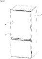
Figure 1 - is a perspective view of the cooling applaince -
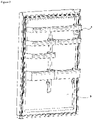
Figure 2 - is a perspective view of the door -
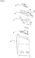
Figure 3 - is an exploded view of the camera module -
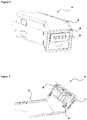
Figure 4 - is a perspective view of the camera module -
Figure 5 - is a cross sectional view of the camera module along dashed A-A lines inFigure 4 - The following numerals are assigned to different parts demonstrated in the drawings and referred to in the present detailed description of the invention:
- 1. Body
- 2. Door
- 3. Inner liner
- 4. Camera module
- 5. Camera housing
- 6. Camera
- 7. Camera holder
- 8. Frame
- 9. Slider
- 10. Indent
- 11. Activation means
- The present invention relates to a cooling appliance comprising; a body (1), a door (2) pivotable attached onto the body (1) between a closed and an open orientation, wherein the door (2) and the body (1) delimits an inner volume in the closed orientation of the door (2), a handle provided on the door (2), an inner liner (3) facing the inner volume, a camera module (4) attached onto the inner liner (3), the camera module (4) comprising; a camera housing (5) for accommodating a camera (6), a camera holder (7) at a front surface of the camera module (4) onto which the camera (6) is placed and via which the camera (6) is enclosed inside the camera housing (5) and wherein the camera holder (7) has an opening through which the inner volume of the cooling appliance is visible by means of the camera (6).
- The present invention further comprises a frame (8) provided on the camera holder (7), a slider (9) slidably placed into the frame (8) between a first orientation during which the slider (9) blocks the view of the camera (6) by closing the opening and a second orientation during which the camera (6) is configured to see the inner volume of the cooling appliance. The body (1) and the door (2) delimits an inner volume wherein the articles to be cooled are placed. The inner volume is surrounded by an inner liner forming an inner surface of the door (2) and the body (1). The camera module (4) is placed onto the inner liner (3) meaning that the camera module (4) can be placed onto the inner liner (3) of the body (1) or onto the inner liner provided on the door (2). In a preferred embodiment the camera module (4) is placed adjacent or underneath a door shelf provided on the door (2). The camera module (4) comprises the camera housing (5) accommodating the operational parts of the camera (6). At the front surface of the camera module (4), the camera holder (7) is provided. The camera holder (7) provides a surface onto which the camera (6) is placed. The camera holder (7) comprises the opening through which the camera (6) establishes visual contact with the inner volume of the cooling appliance. The frame (8) is provided on the camera holder (7) and accommodates the slider (9). The slider (9) is configured to slide between a first orientation and a second orientation. During the first orientation, the slider (9) encloses the opening thereby obstructing the view of the inner volume of the cooling appliance. During the second orientation, the slider (9) moves away from the opening, allowing the camera (6) to view and photograph the inner volume of the cooling appliance. By means of the slider (9), the users are ensured that the camera (6) is not allowed to take pictures or videos of the users and the interior of the household. As a result of this, the users are ensured that their privacy are guaranteed. The slider (9) is a manual solution to the privacy issues raised.
- In the preferred embodiment of the invention, the frame (8) comprises at least an indent (10) immobilizing the slider (9) in the first or the second orientation. The amount of indent (10) can be two or more. The indent (10) is positioned such that the slider (9) can rest in the first orientation or in the second orientation. By means of the indents (10), the slider (9) can be easily positioned on the frame (8).
- In the preferred embodiment of the invention, the camera housing (5) comprises an electrical agitation means (not shown) configured to slide the slider (9) between the first and the second orientation upon activation. The electrical agitation means provides the slider (9) to move between the first orientation and the second orientation. The electrical agitation means can be configured to slide the slider (9) without opening the door (2). Therefore, the users are ensured of their privacy.
- In the preferred embodiment of the invention, an activation means (11) is provided on an outer surface of the body (1), door (2) or the handle, which upon being activated is configured to activate the electrical agitation means to slide the slider (9) between the first and the second orientation. The activation means (11) is provided on an outer surface of the cooling appliance. The activation means (11) can be button or the like as long as it can activate electrical agitation means to slide the slider (9) between the first orientation and the second orientation.
- In the preferred embodiment of the invention, the electrical agitation means is configured to be activated by means of a graphical user interface (GUI). The GUI can be a smart phone, a computer, a tablet or a display provided on the door (2) of the cooling appliance.
- In the preferred embodiment of the invention, a sensor system (not shown) is configured to detect the opening angle between the door (2) and the body (1) in the open orientation and configured to activate the electrical agitation means to slide the slider (9) towards the first orientation at a predetermined angle. The sensor system, upon opening of the door (2), starts to measure the angle between the door (2) and the body (1) and sends a signal to the electrical agitation means when and if the angle exceeds a predetermined angle. The electrical agitation means then activates the slider (9) to slide towards the first orientation. As a result of this, the camera (6) is prevented to visualize the interior of household and the user. On the other hand, the sensor system measures the angle as the door (2) is closed and sends a signal to the electrical agitation means when and if the angle falls below a predetermined angle. As a result of this, the inner volume of the cooling appliance is visualized, meanwhile automatically ensuring user privacy.
- In the preferred embodiment of the invention, the electrical agitation means is an electric motor.
- An advantageous effect provided by means of the invention is that the users are ensured that the camera (6) could not take any visual of the interior of the household. This is achieved manually.
Claims (7)
- A cooling appliance comprising;a body (1),a door (2) pivotable attached onto the body (1) between a closed and an open orientation, wherein the door (2) and the body (1) delimits an inner volume in the closed orientation of the door (2),a handle provided on the door (2),an inner liner (3) facing the inner volume,a camera module (4) attached onto the inner liner (3), the camera module (4) comprising;a camera housing (5) for accommodating a camera (6),a camera holder (7) at a front surface of the camera module (4) onto which the camera (6) is placed and via which the camera (6) is enclosed inside the camera housing (5) and wherein the camera holder (7) has an opening through which the inner volume of the cooling appliance is visible by means of the camera (6),characterized bya frame (8) provided on the camera holder (7),a slider (9) slidably placed into the frame (8) between a first orientation during which the slider (9) blocks the view of the camera (6) by closing the opening and a second orientation during which the camera (6) is configured to see the inner volume of the cooling appliance.
- A cooling appliance according to claim 1, characterized in that the frame (8) comprises at least an indent (10) immobilizing the slider (9) in the first or the second orientation.
- A cooling appliance according any preceding claim, characterized in that the camera housing (5) comprises an electrical agitation means configured to slide the slider (9) between the first and the second orientation upon activation.
- A cooling appliance according to claim 3, characterized by an activation means (11) provided on an outer surface of the body (1), door (2) or the handle, which upon being activated is configured to activate the electrical agitation means to slide the slider (9) between the first and the second orientation.
- A cooling appliance according to claims 3 to 4, characterizedin that the electrical agitation means is configured to be activated by means of a graphical user interface.
- A cooling appliance according to claims 3 to 5, characterized by a sensor system configured to detect the opening angle between the door (2) and the body (1) in the open orientation and configured to activate the electrical agitation means to slide the slider (9) towards the first orientation at a predetermined angle.
- A cooling appliance according to claim 3 to 6, characterized in that the electrical agitation means is an electric motor.
Applications Claiming Priority (1)
| Application Number | Priority Date | Filing Date | Title |
|---|---|---|---|
| TR202104545 | 2021-03-10 |
Publications (2)
| Publication Number | Publication Date |
|---|---|
| EP4057059A1 true EP4057059A1 (en) | 2022-09-14 |
| EP4057059B1 EP4057059B1 (en) | 2023-08-02 |
Family
ID=80461765
Family Applications (1)
| Application Number | Title | Priority Date | Filing Date |
|---|---|---|---|
| EP22158694.4A Active EP4057059B1 (en) | 2021-03-10 | 2022-02-25 | A cooling appliance having means to provide user privacy |
Country Status (2)
| Country | Link |
|---|---|
| EP (1) | EP4057059B1 (en) |
| PL (1) | PL4057059T3 (en) |
Citations (5)
| Publication number | Priority date | Publication date | Assignee | Title |
|---|---|---|---|---|
| DE102013216759A1 (en) | 2013-08-23 | 2015-02-26 | BSH Bosch und Siemens Hausgeräte GmbH | Refrigeration unit with a camera module |
| CN205647718U (en) * | 2016-05-06 | 2016-10-12 | 青岛海尔股份有限公司 | Camera device and have this camera device's refrigerator |
| US20170329206A1 (en) * | 2016-05-13 | 2017-11-16 | Sol Pals, Llc | Camera obstructing device |
| CN208316848U (en) | 2018-06-28 | 2019-01-01 | 合肥联宝信息技术有限公司 | A kind of CCD camera assembly and intelligent refrigerator |
| US20200404137A1 (en) * | 2018-03-09 | 2020-12-24 | Samsung Electronics Co., Ltd | Refrigerator and control method thereof |
-
2022
- 2022-02-25 PL PL22158694.4T patent/PL4057059T3/en unknown
- 2022-02-25 EP EP22158694.4A patent/EP4057059B1/en active Active
Patent Citations (5)
| Publication number | Priority date | Publication date | Assignee | Title |
|---|---|---|---|---|
| DE102013216759A1 (en) | 2013-08-23 | 2015-02-26 | BSH Bosch und Siemens Hausgeräte GmbH | Refrigeration unit with a camera module |
| CN205647718U (en) * | 2016-05-06 | 2016-10-12 | 青岛海尔股份有限公司 | Camera device and have this camera device's refrigerator |
| US20170329206A1 (en) * | 2016-05-13 | 2017-11-16 | Sol Pals, Llc | Camera obstructing device |
| US20200404137A1 (en) * | 2018-03-09 | 2020-12-24 | Samsung Electronics Co., Ltd | Refrigerator and control method thereof |
| CN208316848U (en) | 2018-06-28 | 2019-01-01 | 合肥联宝信息技术有限公司 | A kind of CCD camera assembly and intelligent refrigerator |
Also Published As
| Publication number | Publication date |
|---|---|
| EP4057059B1 (en) | 2023-08-02 |
| PL4057059T3 (en) | 2024-02-05 |
Similar Documents
| Publication | Publication Date | Title |
|---|---|---|
| EP3427630B1 (en) | Method for automatically assessing the displacement of an object in a washing area of a dishwashing machine | |
| CN105051651B (en) | Display device and control method thereof | |
| EP3299756B1 (en) | Refrigerator | |
| US9535310B2 (en) | Security cover on web cameras with parental control | |
| EP1030521A1 (en) | Device and procedure for information on the contents in a cabinet | |
| CN104268968B (en) | Visual entrance guard, safety door latch and safety door with iris identifying function | |
| US20150288882A1 (en) | Internal signal diversion with camera shuttering for mobile communication devices | |
| JP2001317858A (en) | refrigerator | |
| US20140116895A1 (en) | Electronic device case | |
| US20170115545A1 (en) | Optical Device with Electrochromic Lens Cap | |
| FR3111452A1 (en) | Process for the automatic protection of an object, a person or a piece of information or visual work against a risk of unwanted observation | |
| EP4057059B1 (en) | A cooling appliance having means to provide user privacy | |
| CN112513732B (en) | Retrofit covert surveillance guard | |
| EP3068127A1 (en) | Cam-protector | |
| JP2020094802A (en) | refrigerator | |
| CN110873510A (en) | Refrigeration appliance | |
| US20190166290A1 (en) | Imaging apparatus | |
| TR2021004545A2 (en) | COOLING DEVICE WITH MEANS THAT PROVIDE USER PRIVACY | |
| KR101713269B1 (en) | a smart windows having user recognition | |
| US20140265781A1 (en) | Panel with magnetic hinge | |
| CA2873122C (en) | An electronic identity card holder | |
| KR20170050667A (en) | Portable device case | |
| JP2009211130A (en) | Opening/closing count-related information display unit | |
| JP2004295749A (en) | Image monitoring device | |
| EP1679670A1 (en) | Safety handset with defense spray device |
Legal Events
| Date | Code | Title | Description |
|---|---|---|---|
| PUAI | Public reference made under article 153(3) epc to a published international application that has entered the european phase |
Free format text: ORIGINAL CODE: 0009012 |
|
| STAA | Information on the status of an ep patent application or granted ep patent |
Free format text: STATUS: REQUEST FOR EXAMINATION WAS MADE |
|
| 17P | Request for examination filed |
Effective date: 20220225 |
|
| AK | Designated contracting states |
Kind code of ref document: A1 Designated state(s): AL AT BE BG CH CY CZ DE DK EE ES FI FR GB GR HR HU IE IS IT LI LT LU LV MC MK MT NL NO PL PT RO RS SE SI SK SM TR |
|
| GRAP | Despatch of communication of intention to grant a patent |
Free format text: ORIGINAL CODE: EPIDOSNIGR1 |
|
| STAA | Information on the status of an ep patent application or granted ep patent |
Free format text: STATUS: GRANT OF PATENT IS INTENDED |
|
| INTG | Intention to grant announced |
Effective date: 20230406 |
|
| GRAS | Grant fee paid |
Free format text: ORIGINAL CODE: EPIDOSNIGR3 |
|
| GRAA | (expected) grant |
Free format text: ORIGINAL CODE: 0009210 |
|
| STAA | Information on the status of an ep patent application or granted ep patent |
Free format text: STATUS: THE PATENT HAS BEEN GRANTED |
|
| AK | Designated contracting states |
Kind code of ref document: B1 Designated state(s): AL AT BE BG CH CY CZ DE DK EE ES FI FR GB GR HR HU IE IS IT LI LT LU LV MC MK MT NL NO PL PT RO RS SE SI SK SM TR |
|
| REG | Reference to a national code |
Ref country code: GB Ref legal event code: FG4D |
|
| REG | Reference to a national code |
Ref country code: CH Ref legal event code: EP |
|
| REG | Reference to a national code |
Ref country code: DE Ref legal event code: R096 Ref document number: 602022000264 Country of ref document: DE |
|
| REG | Reference to a national code |
Ref country code: IE Ref legal event code: FG4D |
|
| REG | Reference to a national code |
Ref country code: LT Ref legal event code: MG9D |
|
| REG | Reference to a national code |
Ref country code: NL Ref legal event code: MP Effective date: 20230802 |
|
| REG | Reference to a national code |
Ref country code: AT Ref legal event code: MK05 Ref document number: 1595466 Country of ref document: AT Kind code of ref document: T Effective date: 20230802 |
|
| PG25 | Lapsed in a contracting state [announced via postgrant information from national office to epo] |
Ref country code: GR Free format text: LAPSE BECAUSE OF FAILURE TO SUBMIT A TRANSLATION OF THE DESCRIPTION OR TO PAY THE FEE WITHIN THE PRESCRIBED TIME-LIMIT Effective date: 20231103 |
|
| PG25 | Lapsed in a contracting state [announced via postgrant information from national office to epo] |
Ref country code: IS Free format text: LAPSE BECAUSE OF FAILURE TO SUBMIT A TRANSLATION OF THE DESCRIPTION OR TO PAY THE FEE WITHIN THE PRESCRIBED TIME-LIMIT Effective date: 20231202 |
|
| PG25 | Lapsed in a contracting state [announced via postgrant information from national office to epo] |
Ref country code: SE Free format text: LAPSE BECAUSE OF FAILURE TO SUBMIT A TRANSLATION OF THE DESCRIPTION OR TO PAY THE FEE WITHIN THE PRESCRIBED TIME-LIMIT Effective date: 20230802 Ref country code: RS Free format text: LAPSE BECAUSE OF FAILURE TO SUBMIT A TRANSLATION OF THE DESCRIPTION OR TO PAY THE FEE WITHIN THE PRESCRIBED TIME-LIMIT Effective date: 20230802 Ref country code: PT Free format text: LAPSE BECAUSE OF FAILURE TO SUBMIT A TRANSLATION OF THE DESCRIPTION OR TO PAY THE FEE WITHIN THE PRESCRIBED TIME-LIMIT Effective date: 20231204 Ref country code: NO Free format text: LAPSE BECAUSE OF FAILURE TO SUBMIT A TRANSLATION OF THE DESCRIPTION OR TO PAY THE FEE WITHIN THE PRESCRIBED TIME-LIMIT Effective date: 20231102 Ref country code: NL Free format text: LAPSE BECAUSE OF FAILURE TO SUBMIT A TRANSLATION OF THE DESCRIPTION OR TO PAY THE FEE WITHIN THE PRESCRIBED TIME-LIMIT Effective date: 20230802 Ref country code: LV Free format text: LAPSE BECAUSE OF FAILURE TO SUBMIT A TRANSLATION OF THE DESCRIPTION OR TO PAY THE FEE WITHIN THE PRESCRIBED TIME-LIMIT Effective date: 20230802 Ref country code: LT Free format text: LAPSE BECAUSE OF FAILURE TO SUBMIT A TRANSLATION OF THE DESCRIPTION OR TO PAY THE FEE WITHIN THE PRESCRIBED TIME-LIMIT Effective date: 20230802 Ref country code: IS Free format text: LAPSE BECAUSE OF FAILURE TO SUBMIT A TRANSLATION OF THE DESCRIPTION OR TO PAY THE FEE WITHIN THE PRESCRIBED TIME-LIMIT Effective date: 20231202 Ref country code: HR Free format text: LAPSE BECAUSE OF FAILURE TO SUBMIT A TRANSLATION OF THE DESCRIPTION OR TO PAY THE FEE WITHIN THE PRESCRIBED TIME-LIMIT Effective date: 20230802 Ref country code: GR Free format text: LAPSE BECAUSE OF FAILURE TO SUBMIT A TRANSLATION OF THE DESCRIPTION OR TO PAY THE FEE WITHIN THE PRESCRIBED TIME-LIMIT Effective date: 20231103 Ref country code: FI Free format text: LAPSE BECAUSE OF FAILURE TO SUBMIT A TRANSLATION OF THE DESCRIPTION OR TO PAY THE FEE WITHIN THE PRESCRIBED TIME-LIMIT Effective date: 20230802 Ref country code: AT Free format text: LAPSE BECAUSE OF FAILURE TO SUBMIT A TRANSLATION OF THE DESCRIPTION OR TO PAY THE FEE WITHIN THE PRESCRIBED TIME-LIMIT Effective date: 20230802 |
|
| PG25 | Lapsed in a contracting state [announced via postgrant information from national office to epo] |
Ref country code: ES Free format text: LAPSE BECAUSE OF FAILURE TO SUBMIT A TRANSLATION OF THE DESCRIPTION OR TO PAY THE FEE WITHIN THE PRESCRIBED TIME-LIMIT Effective date: 20230802 |
|
| PG25 | Lapsed in a contracting state [announced via postgrant information from national office to epo] |
Ref country code: SM Free format text: LAPSE BECAUSE OF FAILURE TO SUBMIT A TRANSLATION OF THE DESCRIPTION OR TO PAY THE FEE WITHIN THE PRESCRIBED TIME-LIMIT Effective date: 20230802 Ref country code: RO Free format text: LAPSE BECAUSE OF FAILURE TO SUBMIT A TRANSLATION OF THE DESCRIPTION OR TO PAY THE FEE WITHIN THE PRESCRIBED TIME-LIMIT Effective date: 20230802 Ref country code: ES Free format text: LAPSE BECAUSE OF FAILURE TO SUBMIT A TRANSLATION OF THE DESCRIPTION OR TO PAY THE FEE WITHIN THE PRESCRIBED TIME-LIMIT Effective date: 20230802 Ref country code: EE Free format text: LAPSE BECAUSE OF FAILURE TO SUBMIT A TRANSLATION OF THE DESCRIPTION OR TO PAY THE FEE WITHIN THE PRESCRIBED TIME-LIMIT Effective date: 20230802 Ref country code: DK Free format text: LAPSE BECAUSE OF FAILURE TO SUBMIT A TRANSLATION OF THE DESCRIPTION OR TO PAY THE FEE WITHIN THE PRESCRIBED TIME-LIMIT Effective date: 20230802 Ref country code: CZ Free format text: LAPSE BECAUSE OF FAILURE TO SUBMIT A TRANSLATION OF THE DESCRIPTION OR TO PAY THE FEE WITHIN THE PRESCRIBED TIME-LIMIT Effective date: 20230802 Ref country code: SK Free format text: LAPSE BECAUSE OF FAILURE TO SUBMIT A TRANSLATION OF THE DESCRIPTION OR TO PAY THE FEE WITHIN THE PRESCRIBED TIME-LIMIT Effective date: 20230802 |
|
| REG | Reference to a national code |
Ref country code: DE Ref legal event code: R097 Ref document number: 602022000264 Country of ref document: DE |
|
| PG25 | Lapsed in a contracting state [announced via postgrant information from national office to epo] |
Ref country code: IT Free format text: LAPSE BECAUSE OF FAILURE TO SUBMIT A TRANSLATION OF THE DESCRIPTION OR TO PAY THE FEE WITHIN THE PRESCRIBED TIME-LIMIT Effective date: 20230802 |
|
| PLBE | No opposition filed within time limit |
Free format text: ORIGINAL CODE: 0009261 |
|
| STAA | Information on the status of an ep patent application or granted ep patent |
Free format text: STATUS: NO OPPOSITION FILED WITHIN TIME LIMIT |
|
| 26N | No opposition filed |
Effective date: 20240503 |
|
| PG25 | Lapsed in a contracting state [announced via postgrant information from national office to epo] |
Ref country code: SI Free format text: LAPSE BECAUSE OF FAILURE TO SUBMIT A TRANSLATION OF THE DESCRIPTION OR TO PAY THE FEE WITHIN THE PRESCRIBED TIME-LIMIT Effective date: 20230802 |
|
| PG25 | Lapsed in a contracting state [announced via postgrant information from national office to epo] |
Ref country code: MC Free format text: LAPSE BECAUSE OF FAILURE TO SUBMIT A TRANSLATION OF THE DESCRIPTION OR TO PAY THE FEE WITHIN THE PRESCRIBED TIME-LIMIT Effective date: 20230802 |
|
| PG25 | Lapsed in a contracting state [announced via postgrant information from national office to epo] |
Ref country code: LU Free format text: LAPSE BECAUSE OF NON-PAYMENT OF DUE FEES Effective date: 20240225 |
|
| PG25 | Lapsed in a contracting state [announced via postgrant information from national office to epo] |
Ref country code: LU Free format text: LAPSE BECAUSE OF NON-PAYMENT OF DUE FEES Effective date: 20240225 |
|
| PG25 | Lapsed in a contracting state [announced via postgrant information from national office to epo] |
Ref country code: BG Free format text: LAPSE BECAUSE OF FAILURE TO SUBMIT A TRANSLATION OF THE DESCRIPTION OR TO PAY THE FEE WITHIN THE PRESCRIBED TIME-LIMIT Effective date: 20230802 |
|
| PG25 | Lapsed in a contracting state [announced via postgrant information from national office to epo] |
Ref country code: BG Free format text: LAPSE BECAUSE OF FAILURE TO SUBMIT A TRANSLATION OF THE DESCRIPTION OR TO PAY THE FEE WITHIN THE PRESCRIBED TIME-LIMIT Effective date: 20230802 |
|
| REG | Reference to a national code |
Ref country code: BE Ref legal event code: MM Effective date: 20240229 |
|
| PG25 | Lapsed in a contracting state [announced via postgrant information from national office to epo] |
Ref country code: BE Free format text: LAPSE BECAUSE OF NON-PAYMENT OF DUE FEES Effective date: 20240229 |
|
| PG25 | Lapsed in a contracting state [announced via postgrant information from national office to epo] |
Ref country code: FR Free format text: LAPSE BECAUSE OF NON-PAYMENT OF DUE FEES Effective date: 20240229 |
|
| PG25 | Lapsed in a contracting state [announced via postgrant information from national office to epo] |
Ref country code: IE Free format text: LAPSE BECAUSE OF NON-PAYMENT OF DUE FEES Effective date: 20240225 |
|
| PG25 | Lapsed in a contracting state [announced via postgrant information from national office to epo] |
Ref country code: IE Free format text: LAPSE BECAUSE OF NON-PAYMENT OF DUE FEES Effective date: 20240225 Ref country code: FR Free format text: LAPSE BECAUSE OF NON-PAYMENT OF DUE FEES Effective date: 20240229 Ref country code: BE Free format text: LAPSE BECAUSE OF NON-PAYMENT OF DUE FEES Effective date: 20240229 |
|
| PG25 | Lapsed in a contracting state [announced via postgrant information from national office to epo] |
Ref country code: CY Free format text: LAPSE BECAUSE OF FAILURE TO SUBMIT A TRANSLATION OF THE DESCRIPTION OR TO PAY THE FEE WITHIN THE PRESCRIBED TIME-LIMIT; INVALID AB INITIO Effective date: 20220225 |
|
| REG | Reference to a national code |
Ref country code: CH Ref legal event code: PL |
|
| PG25 | Lapsed in a contracting state [announced via postgrant information from national office to epo] |
Ref country code: CH Free format text: LAPSE BECAUSE OF NON-PAYMENT OF DUE FEES Effective date: 20250228 |
|
| PGFP | Annual fee paid to national office [announced via postgrant information from national office to epo] |
Ref country code: GB Payment date: 20260220 Year of fee payment: 5 |
|
| PGFP | Annual fee paid to national office [announced via postgrant information from national office to epo] |
Ref country code: DE Payment date: 20260218 Year of fee payment: 5 |
|
| PGFP | Annual fee paid to national office [announced via postgrant information from national office to epo] |
Ref country code: TR Payment date: 20260203 Year of fee payment: 5 |
|
| PGFP | Annual fee paid to national office [announced via postgrant information from national office to epo] |
Ref country code: PL Payment date: 20260213 Year of fee payment: 5 |
|
| PG25 | Lapsed in a contracting state [announced via postgrant information from national office to epo] |
Ref country code: CH Free format text: THE PATENT HAS BEEN ANNULLED BY A DECISION OF A NATIONAL AUTHORITY Effective date: 20250228 |