EP4056980A1 - System and method for determining strength of a structure - Google Patents
System and method for determining strength of a structure Download PDFInfo
- Publication number
- EP4056980A1 EP4056980A1 EP21161583.6A EP21161583A EP4056980A1 EP 4056980 A1 EP4056980 A1 EP 4056980A1 EP 21161583 A EP21161583 A EP 21161583A EP 4056980 A1 EP4056980 A1 EP 4056980A1
- Authority
- EP
- European Patent Office
- Prior art keywords
- substrate
- joint
- load
- support
- fixture
- Prior art date
- Legal status (The legal status is an assumption and is not a legal conclusion. Google has not performed a legal analysis and makes no representation as to the accuracy of the status listed.)
- Granted
Links
Images


Classifications
-
- G—PHYSICS
- G01—MEASURING; TESTING
- G01M—TESTING STATIC OR DYNAMIC BALANCE OF MACHINES OR STRUCTURES; TESTING OF STRUCTURES OR APPARATUS, NOT OTHERWISE PROVIDED FOR
- G01M5/00—Investigating the elasticity of structures, e.g. deflection of bridges or air-craft wings
- G01M5/0016—Investigating the elasticity of structures, e.g. deflection of bridges or air-craft wings of aircraft wings or blades
-
- G—PHYSICS
- G01—MEASURING; TESTING
- G01N—INVESTIGATING OR ANALYSING MATERIALS BY DETERMINING THEIR CHEMICAL OR PHYSICAL PROPERTIES
- G01N3/00—Investigating strength properties of solid materials by application of mechanical stress
- G01N3/20—Investigating strength properties of solid materials by application of mechanical stress by applying steady bending forces
-
- F—MECHANICAL ENGINEERING; LIGHTING; HEATING; WEAPONS; BLASTING
- F03—MACHINES OR ENGINES FOR LIQUIDS; WIND, SPRING, OR WEIGHT MOTORS; PRODUCING MECHANICAL POWER OR A REACTIVE PROPULSIVE THRUST, NOT OTHERWISE PROVIDED FOR
- F03D—WIND MOTORS
- F03D17/00—Monitoring or testing of wind motors, e.g. diagnostics
-
- G—PHYSICS
- G01—MEASURING; TESTING
- G01M—TESTING STATIC OR DYNAMIC BALANCE OF MACHINES OR STRUCTURES; TESTING OF STRUCTURES OR APPARATUS, NOT OTHERWISE PROVIDED FOR
- G01M5/00—Investigating the elasticity of structures, e.g. deflection of bridges or air-craft wings
- G01M5/0075—Investigating the elasticity of structures, e.g. deflection of bridges or air-craft wings by means of external apparatus, e.g. test benches or portable test systems
-
- G—PHYSICS
- G01—MEASURING; TESTING
- G01N—INVESTIGATING OR ANALYSING MATERIALS BY DETERMINING THEIR CHEMICAL OR PHYSICAL PROPERTIES
- G01N19/00—Investigating materials by mechanical methods
- G01N19/04—Measuring adhesive force between materials, e.g. of sealing tape, of coating
-
- F—MECHANICAL ENGINEERING; LIGHTING; HEATING; WEAPONS; BLASTING
- F03—MACHINES OR ENGINES FOR LIQUIDS; WIND, SPRING, OR WEIGHT MOTORS; PRODUCING MECHANICAL POWER OR A REACTIVE PROPULSIVE THRUST, NOT OTHERWISE PROVIDED FOR
- F03D—WIND MOTORS
- F03D1/00—Wind motors with rotation axis substantially parallel to the air flow entering the rotor
- F03D1/06—Rotors
- F03D1/065—Rotors characterised by their construction elements
- F03D1/0675—Rotors characterised by their construction elements of the blades
-
- F—MECHANICAL ENGINEERING; LIGHTING; HEATING; WEAPONS; BLASTING
- F05—INDEXING SCHEMES RELATING TO ENGINES OR PUMPS IN VARIOUS SUBCLASSES OF CLASSES F01-F04
- F05B—INDEXING SCHEME RELATING TO WIND, SPRING, WEIGHT, INERTIA OR LIKE MOTORS, TO MACHINES OR ENGINES FOR LIQUIDS COVERED BY SUBCLASSES F03B, F03D AND F03G
- F05B2240/00—Components
- F05B2240/20—Rotors
- F05B2240/30—Characteristics of rotor blades, i.e. of any element transforming dynamic fluid energy to or from rotational energy and being attached to a rotor
-
- G—PHYSICS
- G01—MEASURING; TESTING
- G01N—INVESTIGATING OR ANALYSING MATERIALS BY DETERMINING THEIR CHEMICAL OR PHYSICAL PROPERTIES
- G01N2203/00—Investigating strength properties of solid materials by application of mechanical stress
- G01N2203/0014—Type of force applied
- G01N2203/0023—Bending
-
- G—PHYSICS
- G01—MEASURING; TESTING
- G01N—INVESTIGATING OR ANALYSING MATERIALS BY DETERMINING THEIR CHEMICAL OR PHYSICAL PROPERTIES
- G01N2203/00—Investigating strength properties of solid materials by application of mechanical stress
- G01N2203/0058—Kind of property studied
- G01N2203/0091—Peeling or tearing
Definitions
- Present invention relates in general to a field of wind turbines.
- the present invention relates to an apparatus for determining at least one of bending strength of a substrate and peel strength of a joint between the substrate and a structure.
- Embodiments of the present invention relates to the apparatus for determining bending strength of a substrate of a shell and peel strength of a joint between the substrate and a reinforcing structure of the shell of a wind turbine blade.
- Wind power is one of the fastest-growing renewable energy technologies and provides a clean and environmentally friendly source of energy.
- wind turbines comprise a tower, generator, gearbox, nacelle, and one or more rotor blades.
- the kinetic energy of wind is captured using known aerofoil principles.
- Modern wind turbines may have rotor blades that exceed 90 meters in length.
- Turbine blades are the primary elements of wind turbines for converting wind energy into electrical energy.
- the blades have the cross-sectional profile of an airfoil such that, during operation, air flows over the blade producing a pressure difference between the sides. Consequently, a lift force, which is directed from a pressure side towards a suction side, acts on the blade.
- the lift force generates torque on the main rotor shaft, which is geared to a generator for producing electricity.
- Turbine blades are usually manufactured by forming a shell body from two shell parts or shell halves comprising layers of woven fabric or fibre and resin. Spar caps or main laminates are placed or integrated in the shell halves and may be combined with shear webs or spar beams to form structural support members. Spar caps or main laminates may be joined to, or integrated within, the inside of the suction and pressure halves of the shell.
- the shear web is generally bonded or connected to spar caps using suitable bonding paste or adhesive or compound, thus forming bond line or joint between the shear web and the shells, thus connecting the shells.
- wind turbine blade may be subjected to loads, as a result of which bending moments may be generated in the pressure side shell part and in the suction side shell part.
- the bending moments may deform (i.e., resulting in change in shape) the wind turbine blade typically from an airfoil shape to an oval shape.
- This deformation or change in shape of the blade may impose stresses in the components such as shear web, spar cap, adhesive joint between the shear web and the spar cap. The stresses may ultimately cause the components to fail, leading to failure of the blade, which may be undesired.
- an apparatus for determining at least one of a bending strength of a substrate and peel strength of a joint between the substrate and a structure includes a fixture configured to support the structure and a plurality of support beams, each defined with a rolling support at a free end. At least one of the plurality of support beams is provided on either side of the fixture for supporting the substrate, which is joined to the structure. Further, the apparatus includes a plurality of load applying members, configured to apply load onto the substrate, such that the substrate deforms relative to the plurality of support beams, for determining at least one of the bending strength of the substrate and peel strength of the joint between the substrate and the structure.
- the structure is rigidly supported in the fixture by a mechanical joining process.
- the rolling support is a ball joint.
- the apparatus includes a sensor for detecting parameters during application of load onto the substrate, till failure of at least one of the substrate, the structure and the joint between the structure and the substrate.
- the parameters detected by the sensor include: axial load induced in the structure; peel stress in the joint between the substrate and the structure and bending moments on the substrate.
- the senor comprises at least one of: a force transducer; an extensometer; and a load cell.
- the deformation of the substrate relative to the plurality of support beams defines a curve.
- the apparatus comprises a base configured to support the fixture and the plurality of support beams.
- method for determining at least one of a bending strength of a substrate and peel strength of a joint between the substrate and a structure includes a step of supporting, the structure in a fixture, and supporting the substrate on a rolling support defined at a free end of each of a plurality of support beams, wherein the substrate and the structure are joined to each other. Further, the method includes a step of applying, load onto the substrate by a plurality of load applying members to deform the substrate relative to the plurality of support beams, wherein the deformation induces a tensile load in the structure and peel stress in the joint. Furthermore, the method includes a step of determining at least one of the bending strength of the substrate, peel strength of the joint and tensile strength of the structure, based on parameters detected by a sensor during application of the load onto the substrate.
- a system for determining at least one of a bending strength of a substrate of a shell and peel strength of a joint between the substrate and a reinforcing structure of the shell of a wind turbine blade includes a fixture configured to support the structure and a plurality of support beams, each defined with a rolling support at a free end. At least one of the plurality of support beams is provided on either side of the fixture for supporting the substrate, which is joined to the structure.
- the system includes a plurality of load applying members, configured to apply load onto the substrate, such that the substrate deforms relative to the plurality of support beams, for determining at least one of the bending strength of the substrate and peel strength of the joint between the substrate and the structure.
- the term "apparatus” is used to describe a device used to determine at least one of the bending strength of a substrate and peel strength of a joint between the substrate and a structure
- system is used to describe a device for determining at least one of the bending strength of a substrate of a shell and peel strength of a joint between the substrate and a reinforcing structure of the shell of a wind turbine blade.
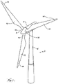
- Fig. 1 illustrates a conventional modern upwind wind turbine according to the so-called "Danish concept" with a tower 4, a nacelle 6 and a rotor with a substantially horizontal rotor shaft.
- the rotor includes a hub 8 and three blades 10 extending radially from the hub 8, each having a blade root 16 nearest the hub 8 and a blade tip 14 farthest from the hub 8.
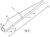
- Fig. 2 shows a schematic view of a wind turbine blade 10.
- the wind turbine blade 10 has the shape of a conventional wind turbine blade 10 and comprises a root region 30 closest to the hub 8, a profiled or an airfoil region 34 farthest away from the hub 8 and a transition region 32 between the root region 30 and the airfoil region 34.
- the blade 10 comprises a leading edge 18 facing the direction of rotation of the blade 10, when the blade 10 is mounted on the hub 8, and a trailing edge 20 facing the opposite direction of the leading edge 18.
- the airfoil region 34 (also called the profiled region) has an ideal or almost ideal blade 10 shape with respect to generating lift, whereas the root region 30 due to structural considerations has a substantially circular or elliptical cross-section, which for instance makes it easier and safer to mount the blade 10 to the hub 8.
- the diameter (or the chord) of the root region 30 may be constant along the entire root area 30.
- the transition region 32 has a transitional profile gradually changing from the circular or elliptical shape of the root region 30 to the airfoil profile of the airfoil region 34.
- the chord length of the transition region 32 typically increases with increasing distance r from the hub 8.
- the airfoil region 34 has an airfoil profile with a chord extending between the leading edge 18 and the trailing edge 20 of the blade 10. The width of the chord decreases with increasing distance r from the hub 8.
- a shoulder 40 of the blade 10 is defined as the position, where the blade 10 has its largest chord length.
- the shoulder 40 is typically provided at the boundary between the transition region 32 and the airfoil region 34.
- Fig. 2 also illustrates the longitudinal extent L, length, or longitudinal axis of the blade 10.
- chords of different sections of the blade 10 normally do not lie in a common plane, since the blade 10 may be twisted and/or curved (i.e., pre-bent), thus providing the chord plane with a correspondingly twisted and/or curved course, this being most often the case to compensate for the local velocity of the blade 10 being dependent on the radius from the hub 8.
- the blade 10 is typically made from a pressure side shell part 36 and a suction side shell part 38 that are glued to each other along bond lines at the leading edge 18 and the trailing edge 20 of the blade 10.
- FIG. 3 is a schematic cut-open, exploded view of a wind turbine blade 10 according to a present invention, wherein Fig. 4 is an enlarged view of the encircled section in Fig. 4 .
- the wind turbine blade 10 comprises a first blade segment 70 and a second blade segment 68 according to the present invention.
- the first blade segment 70 and the second blade segment 68 extends in opposite directions from a chord-wise joint 79.
- the first blade segment 70 is a tip end segment and the second blade segment 68 is a root end segment and both includes a pressure side shell member 76 and a suction side shell member 76.
- Fig. 5 shows a schematic view of a cross section of the blade 10 along the line I-I shown in Fig. 2 .
- the blade 10 comprises a pressure side shell part 36 and a suction side shell part 38.
- the pressure side shell part 36 comprises a spar cap 41, also called a main laminate, which constitutes a load bearing part of the pressure side shell part 36.
- the spar cap 41 comprises a plurality of fibre layers 42 mainly comprising unidirectional fibres aligned along the longitudinal direction of the blade 10 in order to provide stiffness to the blade 10.
- the suction side shell part 38 also comprises a spar cap 45 comprising a plurality of fibre layers 46.
- the pressure side shell part 38 may also comprise a sandwich core material 43 typically made of balsawood or foamed polymer and sandwiched between a number of fibre-reinforced skin layers 52.
- the sandwich core material 43 is used to provide stiffness to the shell in order to ensure that the shell substantially maintains its aerodynamic profile during rotation of the blade 10.
- the suction side shell part 38 may also comprise a sandwich core material 47.
- the spar cap 41 of the pressure side shell part 36 and the spar cap 45 of the suction side shell part 38 are connected via a first shear web 50 and a second shear web 55.
- the shear webs 50, 55 are shown in the embodiment, shaped as substantially I-shaped webs.
- the first shear web 50 comprises a shear web body and two web foot flanges.
- the shear web body comprises a sandwich core material 51, such as balsawood or foamed polymer, covered by a number of skin layers 52 made of a number of fibre layers 42.
- the blade shells 36, 38 may comprise further fibre-reinforcement at the leading edge 18 and the trailing edge 20.
- the shell parts 36, 38 are bonded to each other via glue flanges.
- wind turbine blade 10 may be subjected to loads, as a result of which bending moments may be generated in the pressure side shell part 36 and in the suction side shell part 38.
- the bending moments may deform (i.e. resulting in change in shape) of the wind turbine blade 10 typically from an airfoil shape to an oval shape.
- This deformation or change in shape of the blade 10 may impose stresses in the components such as shear web, spar cap 41, adhesive joint 79 between the shear web and the spar cap 41. The stresses may ultimately cause the components to fail, leading to failure of the blade 10, which is undesired.
- Fig. 6 illustrates an apparatus 71 for determining at least one of a bending strength of a substrate and peel strength of a joint between the substrate and a structure, according to a present invention.
- the apparatus 71 may be adapted to determine the bending strength of the substrate such as a spar cap 41 of the wind turbine blade 10 and peel strength of a joint 79 between the substrate and a reinforcing structure, such as a shear web (50, 55) of the wind turbine blade 10.
- the apparatus 71 may be adapted to determine at least one of the bending strength of a substrate and peel strength of a joint 79 between the substrate and the structure of other types of wind-exposed surfaces negotiating aerodynamic forces, resistance, and aerodynamics, such as helicopter rotor blades or fan blades.
- the apparatus 71 may include a base 72, configured to support other components of the apparatus 71.
- the apparatus 71 may include a fixture 73, supported on the base 72 and may configured to support the reinforcement structure such as a shear web (50, 55) of the wind turbine blade 10.
- the fixture 73 may be configured to rigidly support an end of the reinforcing structure.
- the fixture 73 may include a substantially U-shape configuration, so as to receive one end of the reinforcement structure. Sides of the fixtures 73 may be defined with at least one aperture such that, the reinforcement member 76 may be rigidly supported by mechanical joining process such as but not limiting to fasteners 77.
- the end of the reinforcement structure may be positioned in the fixture 73 and a fastener 77 may extend through the apertures on the sides of the fixture 73 and through the reinforcement structure, such that the reinforcement structure may be rigidly supported by the fixture 73.
- the apparatus 71 may include a plurality of support beams 74, which may be provided on either sides of the fixture 73. Each of the plurality of support beams 74 may extend vertically from the base 72 and may be configured to support the substrate, which may be joined to the reinforcing structure.
- the apparatus 71 may include a plurality of load applying member 76, which may include a rolling support 75 at a free end.
- the plurality of load applying members may be configured to make a surface contact with the substrate and apply load onto the substrate during testing, to deform (thus, bend) the substrate relative to the plurality of support beams 74.
- the apparatus 71 may include a sensor 78 such as but not limiting to a force transducer, an extensometer, and a load cell.
- the sensor 78 may be configured to determine parameters during application of the load (i.e., during the testing), till failure of at least one of the substrate and the reinforcing structure and the joint 79 between the substrate and the reinforcing structure, for determining at least one of the bending strength of the substrate and peel strength of the joint 79 between the substrate and the reinforcing structure.
- the parameters detected by the sensor 78 may include axial load induced in the reinforcing structure, peel stress in the joint 79 between the substrate and the reinforcing structure and bending moments on the substrate which may be analysed further to determine at least one of the bending strength of the reinforcement structure and peel strength of the joint 79 between the reinforcement structure and the substrate.
- the sensor 78 may be communicatively coupled to a control unit [not shown]. The control unit includes set of instructions to receive the inputs from the sensor 78 and determine the axial load induced in the reinforcing structure, peel stress in the joint 79 between the substrate and the reinforcing structure and bending moments on the substrate.
- each of the plurality of support beams 74 may be defined with a rolling support 75 at a free end.
- the rolling support 75 may be a ball joint and may be configured to facilitate bending of the substrate during application of the load, so as to define a curve, thus defining shape of deformation of the blade 10 in real-time conditions.
- configuration of the apparatus 71 allow to apply load on to the substrate (i.e., the spar cap 41 of the wind turbine 2) during testing. This results in bending of the substrate, which corresponds to a real time bending, which is caused due change in shape of the wind turbine blade 10.
- the configuration of the apparatus 71 facilitates in testing the components of the wind turbine blade 10 by mimicking real time conditions, and thus providing accurate results. Based on the strengths determined, the wind turbine blades 10 may be installed in suitable environments.
- the structure may be supported in a fixture 73.
- the structure may be rigidly supported in the fixture 73 by mechanical joining process such as fasteners.
- the substrate may be supported on the rolling support 75 defined at a free end of each of the plurality of support beams 74, with the substrate and the structure being joined to each other using suitable adhesives, forming a joint 79 or a bond line.
- load may be applied onto the substrate by a plurality of load applying members.
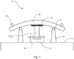
- load may be applied on either sides of the substrate resulting in a four point bending. Due to application of the load, the substrate may deform (thus, bend) [best seen in Fig. 7 ], relative to the plurality of support beams 74. In an embodiment, the deformation of the substrate may induce tensile load in the structure and peel stresses in the joint 79 between the substrate and the structure.
- the sensor 78 may detect the parameters including axial load induced in the structure; peel stress in the joint 79 between the substrate; and the structure and bending moments on the substrate.
- the load application onto the substrate may be continued till failure of at least one of the substrate, the structure and the joint 79 between the structure and the substrate.
- the parameters detected at the point of failure may be computed to determine at least one of the bending strength of a substrate and peel strength of a joint 79 between the substrate and a structure.
- the apparatus 71 may be configured to apply tensile loads onto the substrate such that compressive loads may be induced in the structure, and accordingly the bending strength of the substrate may be determined under tensile loading condition of the substrate and compressive loading condition of the structure.
Landscapes
- General Physics & Mathematics (AREA)
- Physics & Mathematics (AREA)
- Life Sciences & Earth Sciences (AREA)
- Chemical & Material Sciences (AREA)
- Engineering & Computer Science (AREA)
- Immunology (AREA)
- General Health & Medical Sciences (AREA)
- Biochemistry (AREA)
- Analytical Chemistry (AREA)
- Pathology (AREA)
- Health & Medical Sciences (AREA)
- Aviation & Aerospace Engineering (AREA)
- Sustainable Development (AREA)
- Sustainable Energy (AREA)
- Combustion & Propulsion (AREA)
- Mechanical Engineering (AREA)
- General Engineering & Computer Science (AREA)
- Wind Motors (AREA)
- Investigating Strength Of Materials By Application Of Mechanical Stress (AREA)
Abstract
Description
- Present invention relates in general to a field of wind turbines. Particularly, the present invention relates to an apparatus for determining at least one of bending strength of a substrate and peel strength of a joint between the substrate and a structure. Embodiments of the present invention relates to the apparatus for determining bending strength of a substrate of a shell and peel strength of a joint between the substrate and a reinforcing structure of the shell of a wind turbine blade.
- Wind power is one of the fastest-growing renewable energy technologies and provides a clean and environmentally friendly source of energy. Typically, wind turbines comprise a tower, generator, gearbox, nacelle, and one or more rotor blades. The kinetic energy of wind is captured using known aerofoil principles. Modern wind turbines may have rotor blades that exceed 90 meters in length.
- Turbine blades are the primary elements of wind turbines for converting wind energy into electrical energy. The blades have the cross-sectional profile of an airfoil such that, during operation, air flows over the blade producing a pressure difference between the sides. Consequently, a lift force, which is directed from a pressure side towards a suction side, acts on the blade. The lift force generates torque on the main rotor shaft, which is geared to a generator for producing electricity.
- Turbine blades are usually manufactured by forming a shell body from two shell parts or shell halves comprising layers of woven fabric or fibre and resin. Spar caps or main laminates are placed or integrated in the shell halves and may be combined with shear webs or spar beams to form structural support members. Spar caps or main laminates may be joined to, or integrated within, the inside of the suction and pressure halves of the shell. The shear web is generally bonded or connected to spar caps using suitable bonding paste or adhesive or compound, thus forming bond line or joint between the shear web and the shells, thus connecting the shells. During operation of the wind turbine, wind turbine blade may be subjected to loads, as a result of which bending moments may be generated in the pressure side shell part and in the suction side shell part. The bending moments may deform (i.e., resulting in change in shape) the wind turbine blade typically from an airfoil shape to an oval shape. This deformation or change in shape of the blade may impose stresses in the components such as shear web, spar cap, adhesive joint between the shear web and the spar cap. The stresses may ultimately cause the components to fail, leading to failure of the blade, which may be undesired.
- Accordingly, the industry would benefit from a apparatus/ system for determining at least one of a bending strength of a substrate of a shell and peel strength of a joint between the substrate and a reinforcing structure of the shell of a wind turbine blade, for improving service life of the blade.
- In one non-limiting embodiment of the present invention, an apparatus for determining at least one of a bending strength of a substrate and peel strength of a joint between the substrate and a structure, is disclosed. The apparatus includes a fixture configured to support the structure and a plurality of support beams, each defined with a rolling support at a free end. At least one of the plurality of support beams is provided on either side of the fixture for supporting the substrate, which is joined to the structure. Further, the apparatus includes a plurality of load applying members, configured to apply load onto the substrate, such that the substrate deforms relative to the plurality of support beams, for determining at least one of the bending strength of the substrate and peel strength of the joint between the substrate and the structure.
- In an embodiment of the present invention, the structure is rigidly supported in the fixture by a mechanical joining process.
- In an embodiment of the present invention, wherein the rolling support is a ball joint.
- In an embodiment of the present invention, the apparatus includes a sensor for detecting parameters during application of load onto the substrate, till failure of at least one of the substrate, the structure and the joint between the structure and the substrate.
- In an embodiment of the present invention, the parameters detected by the sensor include: axial load induced in the structure; peel stress in the joint between the substrate and the structure and bending moments on the substrate.
- In an embodiment of the present invention, the sensor comprises at least one of: a force transducer; an extensometer; and a load cell.
- In an embodiment of the present invention, the deformation of the substrate relative to the plurality of support beams defines a curve.
- In an embodiment of the present invention, the apparatus comprises a base configured to support the fixture and the plurality of support beams.
- In another non-limiting embodiment of the present invention, method for determining at least one of a bending strength of a substrate and peel strength of a joint between the substrate and a structure, is disclosed. The method includes a step of supporting, the structure in a fixture, and supporting the substrate on a rolling support defined at a free end of each of a plurality of support beams, wherein the substrate and the structure are joined to each other. Further, the method includes a step of applying, load onto the substrate by a plurality of load applying members to deform the substrate relative to the plurality of support beams, wherein the deformation induces a tensile load in the structure and peel stress in the joint. Furthermore, the method includes a step of determining at least one of the bending strength of the substrate, peel strength of the joint and tensile strength of the structure, based on parameters detected by a sensor during application of the load onto the substrate.
- In yet another non-limiting embodiment of the present invention, a system for determining at least one of a bending strength of a substrate of a shell and peel strength of a joint between the substrate and a reinforcing structure of the shell of a wind turbine blade is disclosed. The system includes a fixture configured to support the structure and a plurality of support beams, each defined with a rolling support at a free end. At least one of the plurality of support beams is provided on either side of the fixture for supporting the substrate, which is joined to the structure. Further, the system includes a plurality of load applying members, configured to apply load onto the substrate, such that the substrate deforms relative to the plurality of support beams, for determining at least one of the bending strength of the substrate and peel strength of the joint between the substrate and the structure.
- As used herein in several places, the term "apparatus" is used to describe a device used to determine at least one of the bending strength of a substrate and peel strength of a joint between the substrate and a structure, in general and the term "system" is used to describe a device for determining at least one of the bending strength of a substrate of a shell and peel strength of a joint between the substrate and a reinforcing structure of the shell of a wind turbine blade.
- Various other features will be apparent from the following detailed description and the drawings.
- The invention is explained in detail below with reference to an embodiment shown in the drawings, in which
-
Fig. 1 shows a wind turbine, -
Fig. 2 shows a schematic view of a wind turbine blade, -
Fig. 3 is a schematic cut-open view of the wind turbine blade, -
Fig. 4 is a magnified view of the encircled section inFig. 3 , -
Fig. 5 shows a schematic view of a cross-section of a wind turbine blade, -
Fig. 6 shows a perspective view of an apparatus, according to the present invention. -
Fig. 7 shows a perspective view of the apparatus, with load applied onto the substrate, according to the present invention. -
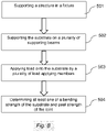
Fig. 8 is a flow chart of a method of determining at least one of a bending strength of a substrate and peel strength of a joint between the substrate and a structure, according to the present invention. -
Fig. 1 illustrates a conventional modern upwind wind turbine according to the so-called "Danish concept" with a tower 4, a nacelle 6 and a rotor with a substantially horizontal rotor shaft. The rotor includes ahub 8 and threeblades 10 extending radially from thehub 8, each having ablade root 16 nearest thehub 8 and ablade tip 14 farthest from thehub 8. -
Fig. 2 shows a schematic view of awind turbine blade 10. Thewind turbine blade 10 has the shape of a conventionalwind turbine blade 10 and comprises aroot region 30 closest to thehub 8, a profiled or anairfoil region 34 farthest away from thehub 8 and atransition region 32 between theroot region 30 and theairfoil region 34. Theblade 10 comprises a leadingedge 18 facing the direction of rotation of theblade 10, when theblade 10 is mounted on thehub 8, and a trailing edge 20 facing the opposite direction of the leadingedge 18. - The airfoil region 34 (also called the profiled region) has an ideal or almost
ideal blade 10 shape with respect to generating lift, whereas theroot region 30 due to structural considerations has a substantially circular or elliptical cross-section, which for instance makes it easier and safer to mount theblade 10 to thehub 8. The diameter (or the chord) of theroot region 30 may be constant along theentire root area 30. Thetransition region 32 has a transitional profile gradually changing from the circular or elliptical shape of theroot region 30 to the airfoil profile of theairfoil region 34. The chord length of thetransition region 32 typically increases with increasing distance r from thehub 8. Theairfoil region 34 has an airfoil profile with a chord extending between the leadingedge 18 and the trailing edge 20 of theblade 10. The width of the chord decreases with increasing distance r from thehub 8. - A shoulder 40 of the
blade 10 is defined as the position, where theblade 10 has its largest chord length. The shoulder 40 is typically provided at the boundary between thetransition region 32 and theairfoil region 34.Fig. 2 also illustrates the longitudinal extent L, length, or longitudinal axis of theblade 10. - It should be noted that the chords of different sections of the
blade 10 normally do not lie in a common plane, since theblade 10 may be twisted and/or curved (i.e., pre-bent), thus providing the chord plane with a correspondingly twisted and/or curved course, this being most often the case to compensate for the local velocity of theblade 10 being dependent on the radius from thehub 8. - The
blade 10 is typically made from a pressureside shell part 36 and a suctionside shell part 38 that are glued to each other along bond lines at theleading edge 18 and the trailing edge 20 of theblade 10. -
Fig. 3 is a schematic cut-open, exploded view of awind turbine blade 10 according to a present invention, whereinFig. 4 is an enlarged view of the encircled section inFig. 4 . - The
wind turbine blade 10 comprises afirst blade segment 70 and a second blade segment 68 according to the present invention. Thefirst blade segment 70 and the second blade segment 68 extends in opposite directions from a chord-wise joint 79. In an embodiment, thefirst blade segment 70 is a tip end segment and the second blade segment 68 is a root end segment and both includes a pressureside shell member 76 and a suctionside shell member 76. -
Fig. 5 shows a schematic view of a cross section of theblade 10 along the line I-I shown inFig. 2 . As previously mentioned, theblade 10 comprises a pressureside shell part 36 and a suctionside shell part 38. The pressureside shell part 36 comprises aspar cap 41, also called a main laminate, which constitutes a load bearing part of the pressureside shell part 36. Thespar cap 41 comprises a plurality of fibre layers 42 mainly comprising unidirectional fibres aligned along the longitudinal direction of theblade 10 in order to provide stiffness to theblade 10. The suctionside shell part 38 also comprises aspar cap 45 comprising a plurality of fibre layers 46. The pressureside shell part 38 may also comprise asandwich core material 43 typically made of balsawood or foamed polymer and sandwiched between a number of fibre-reinforced skin layers 52. Thesandwich core material 43 is used to provide stiffness to the shell in order to ensure that the shell substantially maintains its aerodynamic profile during rotation of theblade 10. Similarly, the suctionside shell part 38 may also comprise asandwich core material 47. - The
spar cap 41 of the pressureside shell part 36 and thespar cap 45 of the suctionside shell part 38 are connected via afirst shear web 50 and asecond shear web 55. Theshear webs first shear web 50 comprises a shear web body and two web foot flanges. The shear web body comprises asandwich core material 51, such as balsawood or foamed polymer, covered by a number of skin layers 52 made of a number of fibre layers 42. Theblade shells leading edge 18 and the trailing edge 20. Typically, theshell parts - During operation of the wind turbine,
wind turbine blade 10 may be subjected to loads, as a result of which bending moments may be generated in the pressureside shell part 36 and in the suctionside shell part 38. The bending moments may deform (i.e. resulting in change in shape) of thewind turbine blade 10 typically from an airfoil shape to an oval shape. This deformation or change in shape of theblade 10 may impose stresses in the components such as shear web,spar cap 41, adhesive joint 79 between the shear web and thespar cap 41. The stresses may ultimately cause the components to fail, leading to failure of theblade 10, which is undesired. Hence, it would be advantageous to determine the bending strength of the shear web, peel strength of the adhesive joint 79 between the shear web and thespar cap 41, based on which the wind turbine may be suitably installed in the desired environment, and thus increasing service life of thewind turbine blade 10. - Accordingly,
Fig. 6 illustrates anapparatus 71 for determining at least one of a bending strength of a substrate and peel strength of a joint between the substrate and a structure, according to a present invention. In an exemplary embodiment, theapparatus 71 may be adapted to determine the bending strength of the substrate such as aspar cap 41 of thewind turbine blade 10 and peel strength of a joint 79 between the substrate and a reinforcing structure, such as a shear web (50, 55) of thewind turbine blade 10. However, the same cannot be considered as a limitation, as theapparatus 71 may be adapted to determine at least one of the bending strength of a substrate and peel strength of a joint 79 between the substrate and the structure of other types of wind-exposed surfaces negotiating aerodynamic forces, resistance, and aerodynamics, such as helicopter rotor blades or fan blades. - As shown in
Fig. 6 , theapparatus 71 may include abase 72, configured to support other components of theapparatus 71. Theapparatus 71 may include afixture 73, supported on thebase 72 and may configured to support the reinforcement structure such as a shear web (50, 55) of thewind turbine blade 10. Thefixture 73 may be configured to rigidly support an end of the reinforcing structure. In an illustrated embodiment, thefixture 73 may include a substantially U-shape configuration, so as to receive one end of the reinforcement structure. Sides of thefixtures 73 may be defined with at least one aperture such that, thereinforcement member 76 may be rigidly supported by mechanical joining process such as but not limiting tofasteners 77. That is, the end of the reinforcement structure may be positioned in thefixture 73 and afastener 77 may extend through the apertures on the sides of thefixture 73 and through the reinforcement structure, such that the reinforcement structure may be rigidly supported by thefixture 73. Further, theapparatus 71 may include a plurality of support beams 74, which may be provided on either sides of thefixture 73. Each of the plurality of support beams 74 may extend vertically from thebase 72 and may be configured to support the substrate, which may be joined to the reinforcing structure. - Further referring to
Fig. 6 , theapparatus 71 may include a plurality ofload applying member 76, which may include a rollingsupport 75 at a free end. The plurality of load applying members may be configured to make a surface contact with the substrate and apply load onto the substrate during testing, to deform (thus, bend) the substrate relative to the plurality of support beams 74. Additionally, theapparatus 71 may include asensor 78 such as but not limiting to a force transducer, an extensometer, and a load cell. Thesensor 78 may be configured to determine parameters during application of the load (i.e., during the testing), till failure of at least one of the substrate and the reinforcing structure and the joint 79 between the substrate and the reinforcing structure, for determining at least one of the bending strength of the substrate and peel strength of the joint 79 between the substrate and the reinforcing structure. - In an embodiment, the parameters detected by the
sensor 78 may include axial load induced in the reinforcing structure, peel stress in the joint 79 between the substrate and the reinforcing structure and bending moments on the substrate which may be analysed further to determine at least one of the bending strength of the reinforcement structure and peel strength of the joint 79 between the reinforcement structure and the substrate. In some embodiments, thesensor 78 may be communicatively coupled to a control unit [not shown]. The control unit includes set of instructions to receive the inputs from thesensor 78 and determine the axial load induced in the reinforcing structure, peel stress in the joint 79 between the substrate and the reinforcing structure and bending moments on the substrate. - In an embodiment and as apparent from
Fig. 6 , each of the plurality of support beams 74 may be defined with a rollingsupport 75 at a free end. The rollingsupport 75 may be a ball joint and may be configured to facilitate bending of the substrate during application of the load, so as to define a curve, thus defining shape of deformation of theblade 10 in real-time conditions. - In an embodiment, configuration of the
apparatus 71 allow to apply load on to the substrate (i.e., thespar cap 41 of the wind turbine 2) during testing. This results in bending of the substrate, which corresponds to a real time bending, which is caused due change in shape of thewind turbine blade 10. Thus, the configuration of theapparatus 71 facilitates in testing the components of thewind turbine blade 10 by mimicking real time conditions, and thus providing accurate results. Based on the strengths determined, thewind turbine blades 10 may be installed in suitable environments. - Referring now to
Fig. 8 , illustrates a flow chart of a method for determining at least one of the bending strength of the substrate and peel strength of the joint 79 between the substrate and the structure. Atblock 501, the structure may be supported in afixture 73. In an embodiment, the structure may be rigidly supported in thefixture 73 by mechanical joining process such as fasteners. Once, the structure is supported in thefixture 73 atblock 502, the substrate may be supported on the rollingsupport 75 defined at a free end of each of the plurality of support beams 74, with the substrate and the structure being joined to each other using suitable adhesives, forming a joint 79 or a bond line. - At
block 503, load may be applied onto the substrate by a plurality of load applying members. In an exemplary embodiment, load may be applied on either sides of the substrate resulting in a four point bending. Due to application of the load, the substrate may deform (thus, bend) [best seen inFig. 7 ], relative to the plurality of support beams 74. In an embodiment, the deformation of the substrate may induce tensile load in the structure and peel stresses in the joint 79 between the substrate and the structure. - At
block 504, during application of load onto the substrate, thesensor 78 may detect the parameters including axial load induced in the structure; peel stress in the joint 79 between the substrate; and the structure and bending moments on the substrate. The load application onto the substrate may be continued till failure of at least one of the substrate, the structure and the joint 79 between the structure and the substrate. The parameters detected at the point of failure may be computed to determine at least one of the bending strength of a substrate and peel strength of a joint 79 between the substrate and a structure. - In an embodiment, in an embodiment the
apparatus 71 may be configured to apply tensile loads onto the substrate such that compressive loads may be induced in the structure, and accordingly the bending strength of the substrate may be determined under tensile loading condition of the substrate and compressive loading condition of the structure. - Exemplary embodiments of the present disclosure are set out in the following items:
- 1. An apparatus for determining at least one of a bending strength of a substrate and peel strength of a joint between the substrate and a structure, the apparatus comprising:
- a fixture configured to support the structure;
- a plurality of support beams, each defined with a rolling support at a free end, wherein at least one of the plurality of support beams is provided on either side of the fixture for supporting the substrate, which is joined to the structure; and
- a plurality of load applying members, configured to apply load onto the substrate, such that the substrate deforms relative to the plurality of support beams, for determining at least one of the bending strength of the substrate and peel strength of the joint between the substrate and the structure.
- 2. The apparatus according to item 1, wherein the structure is rigidly supported in the fixture by a mechanical joining process.
- 3. The apparatus according to any of items 1-2, wherein the rolling support is a ball joint.
- 4. The apparatus according to any of items 1-3, comprises a sensor for detecting parameters during application of load onto the substrate, till failure of at least one of: the substrate, the structure and the joint between the structure and the substrate.
- 5. The apparatus according to item 4, wherein the parameters detected by the sensor comprises: axial load induced in the structure; peel stress in the joint between the substrate and the structure; and bending moments on the substrate.
- 6. The apparatus according to any of items 4-5, wherein the sensor comprises at least one of: a force transducer; an extensometer; and a load cell.
- 7. The apparatus according to any of items 1-6, wherein the plurality of load applying members comprises a rolling support at a free end for applying load onto the substrate.
- 8. The apparatus according to any of items 1-7, wherein the deformation of the substrate relative to the plurality of support beams defines a curve.
- 9. The apparatus according to any of items 1-8, comprises a base configured to support the fixture and the plurality of support beams.
- 10. A method for determining at least one of a bending strength of a substrate and peel strength of a joint between the substrate and a structure, the method comprising:
- supporting, the structure in a fixture;
- supporting, the substrate on a rolling support defined at a free end of each of a plurality of support beams, wherein the substrate and the structure are joined to each other;
- applying, load onto the substrate by a plurality of load applying members to deform the substrate relative to the plurality of support beams, wherein the deformation induces a tensile load in the structure and peel stress in the joint; and
- determining at least one of the bending strength of the substrate, peel strength of the joint and tensile strength of the structure, based on parameters detected by a sensor during application of the load onto the substrate.
- 11. The method according to
item 10, wherein the sensor detects the parameters till failure o:f at least one of the substrate; the structure; and the joint between the substrate and the structure. - 12. The method according to any of items 10-11, wherein the parameters detected by the sensor comrpises an axial load induced in the structure; peel stress in the joint between the substrate and the structure; and bending moments on the substrate.
- 13. A system for determining at least one of a bending strength of a substrate of a shell and peel strength of a joint between the substrate and a reinforcing structure of the shell of a wind turbine blade, the system comprising:
- a fixture configured to support the reinforcing structure;
- a plurality of support beams, each defined with a rolling support at a free end, wherein at least one the plurality of support beams is provided on either side of the fixture for supporting the substrate, which is joined to the reinforcing structure;
- a plurality of load applying members, configured to apply load onto the substrate, such that the substrate deforms relative to the plurality of support beams; and
- a sensor for detecting parameters during application of the load onto the substrate, for determining at least one of the bending strength of the substrate and peel strength of the joint between the substrate and the reinforcing structure.
- 14. The system according to item 13, wherein the substrate is a spar of the wind turbine blade.
- 15. The system according to any of items 13-14, wherein the reinforcing structure is a shear web of the wind turbine blade.
- 16. The system according to any of items 13-15, wherein the sensor detects the parameters till failure of at least one of: the substrate; the reinforcing structure; and the joint between the substrate and the reinforcing structure.
- 17. The system according to any of items 13-16, wherein the parameters detected by the sensor comprises: axial load induced in the reinforcing structure; peel stress in the joint between the substrate; and the reinforcing structure and bending moments on the substrate.
- 18. The system according to any of items 13-17, wherein the reinforcing structure is rigidly supported in the fixture by mechanical joining process.
- 19. The system according to any of items 13-18, wherein the sensor comprises one of:
a force transducer; an extensometer; and a load cell, and the rolling support is a ball joint. - 20. The system according to any of items 13-19, wherein the plurality of load applying members comprises a rolling support at a free end, for applying load onto the substrate.
-
- 2
- wind turbine
- 4
- tower
- 6
- nacelle
- 8
- hub
- 10
- blade
- 14
- blade tip
- 16
- blade root
- 18
- leading edge
- 20
- trailing edge
- 30
- root region
- 32
- transition region
- 34
- airfoil region
- 36
- pressure side shell part
- 38
- suction side shell part
- 40
- shoulder
- 41
- spar cap
- 42
- fibre layers
- 43
- sandwich core material
- 46
- fibre layers
- 47
- sandwich core material
- 50
- first shear web
- 51
- core member
- 52
- skin layers
- 55
- second shear web
- 56
- sandwich core material of second shear web
- 57
- skin layers of second shear web
- 60
- filler ropes
- 68
- second blade segment
- 70
- first blade segment
- 71
- apparatus
- 72
- base
- 73
- fixture
- 74
- support beams
- 75
- rolling support
- 76
- load applying member
- 77
- fastener
- 78
- sensor
- 79
- joint
Claims (15)
- An apparatus for determining at least one of a bending strength of a substrate and peel strength of a joint between the substrate and a structure, the apparatus comprising:a fixture configured to support the structure;a plurality of support beams, each defined with a rolling support at a free end, wherein at least one of the plurality of support beams is provided on either side of the fixture for supporting the substrate, which is joined to the structure; anda plurality of load applying members, configured to apply load onto the substrate, such that the substrate deforms relative to the plurality of support beams, for determining at least one of the bending strength of the substrate and peel strength of the joint between the substrate and the structure.
- The apparatus according to claim 1, wherein the structure is rigidly supported in the fixture by a mechanical joining process.
- The apparatus according to any of claims 1-2, wherein the rolling support is a ball joint.
- The apparatus according to any of claims 1-3, comprises a sensor for detecting parameters during application of load onto the substrate, till failure of at least one of: the substrate, the structure and the joint between the structure and the substrate, e.g.wherein the parameters detected by the sensor comprises: axial load induced in the structure; peel stress in the joint between the substrate and the structure; and bending moments on the substrate, and/orwherein the sensor comprises at least one of: a force transducer; an extensometer; and a load cell.
- The apparatus according to any of claims 1-4, wherein the plurality of load applying members comprises a rolling support at a free end for applying load onto the substrate.
- The apparatus according to any of claims 1-5, wherein the deformation of the substrate relative to the plurality of support beams defines a curve.
- The apparatus according to any of claims 1-6, comprises a base configured to support the fixture and the plurality of support beams.
- A method for determining at least one of a bending strength of a substrate and peel strength of a joint between the substrate and a structure, the method comprising:supporting, the structure in a fixture;supporting, the substrate on a rolling support defined at a free end of each of a plurality of support beams, wherein the substrate and the structure are joined to each other;applying, load onto the substrate by a plurality of load applying members to deform the substrate relative to the plurality of support beams, wherein the deformation induces a tensile load in the structure and peel stress in the joint; anddetermining at least one of the bending strength of the substrate, peel strength of the joint and tensile strength of the structure, based on parameters detected by a sensor during application of the load onto the substrate.
- The method according to claim 8, wherein the sensor detects the parameters till failure of: at least one of the substrate; the structure; and the joint between the substrate and the structure.
- The method according to any of claims 8-9, wherein the parameters detected by the sensor comprises an axial load induced in the structure; peel stress in the joint between the substrate and the structure; and bending moments on the substrate.
- A system for determining at least one of a bending strength of a substrate of a shell and peel strength of a joint between the substrate and a reinforcing structure of the shell of a wind turbine blade, the system comprising:a fixture configured to support the reinforcing structure;a plurality of support beams, each defined with a rolling support at a free end, wherein at least one the plurality of support beams is provided on either side of the fixture for supporting the substrate, which is joined to the reinforcing structure;a plurality of load applying members, configured to apply load onto the substrate, such that the substrate deforms relative to the plurality of support beams; anda sensor for detecting parameters during application of the load onto the substrate, for determining at least one of the bending strength of the substrate and peel strength of the joint between the substrate and the reinforcing structure.
- The system according to claim 11, wherein the substrate is a spar of the wind turbine blade.
- The system according to any of claims 11-12, wherein the reinforcing structure is a shear web of the wind turbine blade.
- The system according to any of claims 11-13, wherein the sensor detects the parameters till failure of at least one of: the substrate; the reinforcing structure; and the joint between the substrate and the reinforcing structure, e.g. wherein the parameters detected by the sensor comprises: axial load induced in the reinforcing structure; peel stress in the joint between the substrate; and the reinforcing structure and bending moments on the substrate
- The system according to any of claims 11-14, wherein the reinforcing structure is rigidly supported in the fixture by mechanical joining process, and/orwherein the sensor comprises one of: a force transducer; an extensometer; and a load cell, and the rolling support is a ball joint, and/orwherein the plurality of load applying members comprises a rolling support at a free end, for applying load onto the substrate.
Priority Applications (5)
| Application Number | Priority Date | Filing Date | Title |
|---|---|---|---|
| MA71711A MA71711A (en) | 2021-03-09 | 2021-03-09 | SYSTEM AND METHOD FOR DETERMINING THE STRENGTH OF A STRUCTURE |
| DK21161583.6T DK4056980T3 (en) | 2021-03-09 | 2021-03-09 | System and method for determining strength of a structure |
| EP21161583.6A EP4056980B1 (en) | 2021-03-09 | 2021-03-09 | System and method for determining strength of a structure |
| US17/689,341 US11988646B2 (en) | 2021-03-09 | 2022-03-08 | Apparatus and method for determining strength of a substrate and peal strength of a joint between the substrate and structure with load applying elements |
| CN202210224257.XA CN115045804A (en) | 2021-03-09 | 2022-03-09 | System and method for determining strength of structure |
Applications Claiming Priority (1)
| Application Number | Priority Date | Filing Date | Title |
|---|---|---|---|
| EP21161583.6A EP4056980B1 (en) | 2021-03-09 | 2021-03-09 | System and method for determining strength of a structure |
Publications (2)
| Publication Number | Publication Date |
|---|---|
| EP4056980A1 true EP4056980A1 (en) | 2022-09-14 |
| EP4056980B1 EP4056980B1 (en) | 2025-10-29 |
Family
ID=74870615
Family Applications (1)
| Application Number | Title | Priority Date | Filing Date |
|---|---|---|---|
| EP21161583.6A Active EP4056980B1 (en) | 2021-03-09 | 2021-03-09 | System and method for determining strength of a structure |
Country Status (5)
| Country | Link |
|---|---|
| US (1) | US11988646B2 (en) |
| EP (1) | EP4056980B1 (en) |
| CN (1) | CN115045804A (en) |
| DK (1) | DK4056980T3 (en) |
| MA (1) | MA71711A (en) |
Cited By (1)
| Publication number | Priority date | Publication date | Assignee | Title |
|---|---|---|---|---|
| US20220291101A1 (en) * | 2021-03-09 | 2022-09-15 | Lm Wind Power A/S | System and method for determining strength of a structure |
Citations (5)
| Publication number | Priority date | Publication date | Assignee | Title |
|---|---|---|---|---|
| US5231882A (en) * | 1991-02-16 | 1993-08-03 | Telefunken Systemtechnik Gmbh | Testing device for performing four-point fatigue strength tests under alternating bending stresses |
| JP2000094177A (en) * | 1998-09-22 | 2000-04-04 | Hitachi Ltd | Fatigue test jig for welded joints |
| US20100206062A1 (en) * | 2009-02-13 | 2010-08-19 | Samsung Electronics Co., Ltd. | Adhesion test method using elastic plate |
| EP2679980A2 (en) * | 2012-06-25 | 2014-01-01 | The Boeing Company | System and method for testing a fillet bond |
| CN103698225B (en) * | 2013-12-16 | 2016-01-13 | 中国科学院长春光学精密机械与物理研究所 | Four-point bending elastic parameter measuring method and measuring system |
Family Cites Families (2)
| Publication number | Priority date | Publication date | Assignee | Title |
|---|---|---|---|---|
| GB202007762D0 (en) * | 2020-05-25 | 2020-07-08 | Lm Wind Power As | Specimen test method |
| DK4056980T3 (en) * | 2021-03-09 | 2026-02-02 | Lm Wind Power As | System and method for determining strength of a structure |
-
2021
- 2021-03-09 DK DK21161583.6T patent/DK4056980T3/en active
- 2021-03-09 EP EP21161583.6A patent/EP4056980B1/en active Active
- 2021-03-09 MA MA71711A patent/MA71711A/en unknown
-
2022
- 2022-03-08 US US17/689,341 patent/US11988646B2/en active Active
- 2022-03-09 CN CN202210224257.XA patent/CN115045804A/en active Pending
Patent Citations (5)
| Publication number | Priority date | Publication date | Assignee | Title |
|---|---|---|---|---|
| US5231882A (en) * | 1991-02-16 | 1993-08-03 | Telefunken Systemtechnik Gmbh | Testing device for performing four-point fatigue strength tests under alternating bending stresses |
| JP2000094177A (en) * | 1998-09-22 | 2000-04-04 | Hitachi Ltd | Fatigue test jig for welded joints |
| US20100206062A1 (en) * | 2009-02-13 | 2010-08-19 | Samsung Electronics Co., Ltd. | Adhesion test method using elastic plate |
| EP2679980A2 (en) * | 2012-06-25 | 2014-01-01 | The Boeing Company | System and method for testing a fillet bond |
| CN103698225B (en) * | 2013-12-16 | 2016-01-13 | 中国科学院长春光学精密机械与物理研究所 | Four-point bending elastic parameter measuring method and measuring system |
Cited By (2)
| Publication number | Priority date | Publication date | Assignee | Title |
|---|---|---|---|---|
| US20220291101A1 (en) * | 2021-03-09 | 2022-09-15 | Lm Wind Power A/S | System and method for determining strength of a structure |
| US11988646B2 (en) * | 2021-03-09 | 2024-05-21 | Lm Wind Power A/S | Apparatus and method for determining strength of a substrate and peal strength of a joint between the substrate and structure with load applying elements |
Also Published As
| Publication number | Publication date |
|---|---|
| US20220291101A1 (en) | 2022-09-15 |
| MA71711A (en) | 2025-05-30 |
| DK4056980T3 (en) | 2026-02-02 |
| US11988646B2 (en) | 2024-05-21 |
| EP4056980B1 (en) | 2025-10-29 |
| CN115045804A (en) | 2022-09-13 |
Similar Documents
| Publication | Publication Date | Title |
|---|---|---|
| DK3027893T3 (en) | A wind turbine wing with a fortress line next to a sandwich panel in the wing | |
| US12049865B2 (en) | Wind turbine blade with a plurality of shear webs | |
| EP3857053B1 (en) | Jointed wind turbine blade with noise reduction tape | |
| US12560515B2 (en) | Specimen test method | |
| US11988646B2 (en) | Apparatus and method for determining strength of a substrate and peal strength of a joint between the substrate and structure with load applying elements | |
| EP3857049B1 (en) | Method to reduce noise and vibration in a jointed wind turbine blade, and associated wind turbine blade | |
| WO2020122869A1 (en) | Segmented rotor blade having maximized overall pre-bend via an increased pre-bend in a blade tip segment thereof | |
| EP4019229A1 (en) | Method of manufacturing a wind turbine blade using a distance member for connecting the wind turbine blade shear webs and wind turbine blade with a distance member connecting the wind turbine blade shear webs | |
| EP3874150B1 (en) | Sealing member for a sectioned wind turbine blade | |
| EP4127454B1 (en) | METHOD FOR MANUFACTURING A WIND TURBINE SHAFTS AND SHEAR PLATE ARRANGEMENT FOR A WIND TURBINE SHAFTS | |
| US20240352917A1 (en) | Segmented wind turbine blade | |
| WO2022189562A1 (en) | An apparatus for determining orientation of a segment of a wind turbine blade and a method thereof | |
| WO2022096409A1 (en) | A mechanism for connecting an elongated member and a receiving portion | |
| CN117255895A (en) | Rotor blade for a wind turbine, wind turbine and method for manufacturing a rotor blade | |
| CN218787893U (en) | Mounting structure and wind turbine blade section test assembly | |
| Davison | The Boeing MOD-2 wind turbine system rotor |
Legal Events
| Date | Code | Title | Description |
|---|---|---|---|
| PUAI | Public reference made under article 153(3) epc to a published international application that has entered the european phase |
Free format text: ORIGINAL CODE: 0009012 |
|
| STAA | Information on the status of an ep patent application or granted ep patent |
Free format text: STATUS: THE APPLICATION HAS BEEN PUBLISHED |
|
| AK | Designated contracting states |
Kind code of ref document: A1 Designated state(s): AL AT BE BG CH CY CZ DE DK EE ES FI FR GB GR HR HU IE IS IT LI LT LU LV MC MK MT NL NO PL PT RO RS SE SI SK SM TR |
|
| STAA | Information on the status of an ep patent application or granted ep patent |
Free format text: STATUS: REQUEST FOR EXAMINATION WAS MADE |
|
| 17P | Request for examination filed |
Effective date: 20230314 |
|
| RAV | Requested validation state of the european patent: fee paid |
Extension state: MA Effective date: 20230314 |
|
| RBV | Designated contracting states (corrected) |
Designated state(s): AL AT BE BG CH CY CZ DE DK EE ES FI FR GB GR HR HU IE IS IT LI LT LU LV MC MK MT NL NO PL PT RO RS SE SI SK SM TR |
|
| P01 | Opt-out of the competence of the unified patent court (upc) registered |
Effective date: 20230522 |
|
| STAA | Information on the status of an ep patent application or granted ep patent |
Free format text: STATUS: EXAMINATION IS IN PROGRESS |
|
| 17Q | First examination report despatched |
Effective date: 20241107 |
|
| GRAP | Despatch of communication of intention to grant a patent |
Free format text: ORIGINAL CODE: EPIDOSNIGR1 |
|
| STAA | Information on the status of an ep patent application or granted ep patent |
Free format text: STATUS: GRANT OF PATENT IS INTENDED |
|
| RIC1 | Information provided on ipc code assigned before grant |
Ipc: G01N 19/04 20060101ALI20250514BHEP Ipc: G01N 3/20 20060101ALI20250514BHEP Ipc: G01M 5/00 20060101AFI20250514BHEP |
|
| INTG | Intention to grant announced |
Effective date: 20250527 |
|
| GRAS | Grant fee paid |
Free format text: ORIGINAL CODE: EPIDOSNIGR3 |
|
| GRAA | (expected) grant |
Free format text: ORIGINAL CODE: 0009210 |
|
| STAA | Information on the status of an ep patent application or granted ep patent |
Free format text: STATUS: THE PATENT HAS BEEN GRANTED |
|
| AK | Designated contracting states |
Kind code of ref document: B1 Designated state(s): AL AT BE BG CH CY CZ DE DK EE ES FI FR GB GR HR HU IE IS IT LI LT LU LV MC MK MT NL NO PL PT RO RS SE SI SK SM TR |
|
| REG | Reference to a national code |
Ref country code: CH Ref legal event code: F10 Free format text: ST27 STATUS EVENT CODE: U-0-0-F10-F00 (AS PROVIDED BY THE NATIONAL OFFICE) Effective date: 20251029 Ref country code: GB Ref legal event code: FG4D |
|
| REG | Reference to a national code |
Ref country code: IE Ref legal event code: FG4D |
|
| REG | Reference to a national code |
Ref country code: DE Ref legal event code: R096 Ref document number: 602021041116 Country of ref document: DE |
|
| REG | Reference to a national code |
Ref country code: DK Ref legal event code: T3 Effective date: 20260126 |
|
| REG | Reference to a national code |
Ref country code: NL Ref legal event code: MP Effective date: 20251029 |
|
| PGFP | Annual fee paid to national office [announced via postgrant information from national office to epo] |
Ref country code: GB Payment date: 20260220 Year of fee payment: 6 |
|
| PG25 | Lapsed in a contracting state [announced via postgrant information from national office to epo] |
Ref country code: ES Free format text: LAPSE BECAUSE OF FAILURE TO SUBMIT A TRANSLATION OF THE DESCRIPTION OR TO PAY THE FEE WITHIN THE PRESCRIBED TIME-LIMIT Effective date: 20251029 |
|
| REG | Reference to a national code |
Ref country code: LT Ref legal event code: MG9D |
|
| PG25 | Lapsed in a contracting state [announced via postgrant information from national office to epo] |
Ref country code: NO Free format text: LAPSE BECAUSE OF FAILURE TO SUBMIT A TRANSLATION OF THE DESCRIPTION OR TO PAY THE FEE WITHIN THE PRESCRIBED TIME-LIMIT Effective date: 20260129 |
|
| PGFP | Annual fee paid to national office [announced via postgrant information from national office to epo] |
Ref country code: DK Payment date: 20260219 Year of fee payment: 6 Ref country code: DE Payment date: 20260219 Year of fee payment: 6 |
|
| PG25 | Lapsed in a contracting state [announced via postgrant information from national office to epo] |
Ref country code: HR Free format text: LAPSE BECAUSE OF FAILURE TO SUBMIT A TRANSLATION OF THE DESCRIPTION OR TO PAY THE FEE WITHIN THE PRESCRIBED TIME-LIMIT Effective date: 20251029 Ref country code: AT Free format text: LAPSE BECAUSE OF FAILURE TO SUBMIT A TRANSLATION OF THE DESCRIPTION OR TO PAY THE FEE WITHIN THE PRESCRIBED TIME-LIMIT Effective date: 20251029 Ref country code: FI Free format text: LAPSE BECAUSE OF FAILURE TO SUBMIT A TRANSLATION OF THE DESCRIPTION OR TO PAY THE FEE WITHIN THE PRESCRIBED TIME-LIMIT Effective date: 20251029 |
|
| REG | Reference to a national code |
Ref country code: AT Ref legal event code: MK05 Ref document number: 1852042 Country of ref document: AT Kind code of ref document: T Effective date: 20251029 |
|
| PG25 | Lapsed in a contracting state [announced via postgrant information from national office to epo] |
Ref country code: NL Free format text: LAPSE BECAUSE OF FAILURE TO SUBMIT A TRANSLATION OF THE DESCRIPTION OR TO PAY THE FEE WITHIN THE PRESCRIBED TIME-LIMIT Effective date: 20251029 |
|
| PG25 | Lapsed in a contracting state [announced via postgrant information from national office to epo] |
Ref country code: RS Free format text: LAPSE BECAUSE OF FAILURE TO SUBMIT A TRANSLATION OF THE DESCRIPTION OR TO PAY THE FEE WITHIN THE PRESCRIBED TIME-LIMIT Effective date: 20260129 |
|
| PG25 | Lapsed in a contracting state [announced via postgrant information from national office to epo] |
Ref country code: IS Free format text: LAPSE BECAUSE OF FAILURE TO SUBMIT A TRANSLATION OF THE DESCRIPTION OR TO PAY THE FEE WITHIN THE PRESCRIBED TIME-LIMIT Effective date: 20260228 |
|
| PGFP | Annual fee paid to national office [announced via postgrant information from national office to epo] |
Ref country code: FR Payment date: 20260219 Year of fee payment: 6 |
|
| PG25 | Lapsed in a contracting state [announced via postgrant information from national office to epo] |
Ref country code: PT Free format text: LAPSE BECAUSE OF FAILURE TO SUBMIT A TRANSLATION OF THE DESCRIPTION OR TO PAY THE FEE WITHIN THE PRESCRIBED TIME-LIMIT Effective date: 20260302 |
|
| PG25 | Lapsed in a contracting state [announced via postgrant information from national office to epo] |
Ref country code: PL Free format text: LAPSE BECAUSE OF FAILURE TO SUBMIT A TRANSLATION OF THE DESCRIPTION OR TO PAY THE FEE WITHIN THE PRESCRIBED TIME-LIMIT Effective date: 20251029 |
|
| PG25 | Lapsed in a contracting state [announced via postgrant information from national office to epo] |
Ref country code: LV Free format text: LAPSE BECAUSE OF FAILURE TO SUBMIT A TRANSLATION OF THE DESCRIPTION OR TO PAY THE FEE WITHIN THE PRESCRIBED TIME-LIMIT Effective date: 20251029 |
|
| PG25 | Lapsed in a contracting state [announced via postgrant information from national office to epo] |
Ref country code: BG Free format text: LAPSE BECAUSE OF FAILURE TO SUBMIT A TRANSLATION OF THE DESCRIPTION OR TO PAY THE FEE WITHIN THE PRESCRIBED TIME-LIMIT Effective date: 20251029 |