EP4056979A1 - Power transmission device - Google Patents
Power transmission device Download PDFInfo
- Publication number
- EP4056979A1 EP4056979A1 EP21763490.6A EP21763490A EP4056979A1 EP 4056979 A1 EP4056979 A1 EP 4056979A1 EP 21763490 A EP21763490 A EP 21763490A EP 4056979 A1 EP4056979 A1 EP 4056979A1
- Authority
- EP
- European Patent Office
- Prior art keywords
- housing
- pair
- commutators
- rotating shaft
- brush
- Prior art date
- Legal status (The legal status is an assumption and is not a legal conclusion. Google has not performed a legal analysis and makes no representation as to the accuracy of the status listed.)
- Granted
Links
Images



Classifications
-
- G—PHYSICS
- G01—MEASURING; TESTING
- G01M—TESTING STATIC OR DYNAMIC BALANCE OF MACHINES OR STRUCTURES; TESTING OF STRUCTURES OR APPARATUS, NOT OTHERWISE PROVIDED FOR
- G01M3/00—Investigating fluid-tightness of structures
- G01M3/02—Investigating fluid-tightness of structures by using fluid or vacuum
- G01M3/025—Details with respect to the testing of engines or engine parts
-
- G—PHYSICS
- G01—MEASURING; TESTING
- G01M—TESTING STATIC OR DYNAMIC BALANCE OF MACHINES OR STRUCTURES; TESTING OF STRUCTURES OR APPARATUS, NOT OTHERWISE PROVIDED FOR
- G01M3/00—Investigating fluid-tightness of structures
- G01M3/02—Investigating fluid-tightness of structures by using fluid or vacuum
- G01M3/04—Investigating fluid-tightness of structures by using fluid or vacuum by detecting the presence of fluid at the leakage point
- G01M3/16—Investigating fluid-tightness of structures by using fluid or vacuum by detecting the presence of fluid at the leakage point using electric detection means
-
- F—MECHANICAL ENGINEERING; LIGHTING; HEATING; WEAPONS; BLASTING
- F16—ENGINEERING ELEMENTS AND UNITS; GENERAL MEASURES FOR PRODUCING AND MAINTAINING EFFECTIVE FUNCTIONING OF MACHINES OR INSTALLATIONS; THERMAL INSULATION IN GENERAL
- F16H—GEARING
- F16H57/00—General details of gearing
- F16H57/02—Gearboxes; Mounting gearing therein
- F16H57/029—Gearboxes; Mounting gearing therein characterised by means for sealing the gearboxes, e.g. to improve airtightness
-
- F—MECHANICAL ENGINEERING; LIGHTING; HEATING; WEAPONS; BLASTING
- F16—ENGINEERING ELEMENTS AND UNITS; GENERAL MEASURES FOR PRODUCING AND MAINTAINING EFFECTIVE FUNCTIONING OF MACHINES OR INSTALLATIONS; THERMAL INSULATION IN GENERAL
- F16J—PISTONS; CYLINDERS; SEALINGS
- F16J15/00—Sealings
- F16J15/16—Sealings between relatively-moving surfaces
- F16J15/32—Sealings between relatively-moving surfaces with elastic sealings, e.g. O-rings
- F16J15/3296—Arrangements for monitoring the condition or operation of elastic sealings; Arrangements for control of elastic sealings, e.g. of their geometry or stiffness
-
- G—PHYSICS
- G01—MEASURING; TESTING
- G01M—TESTING STATIC OR DYNAMIC BALANCE OF MACHINES OR STRUCTURES; TESTING OF STRUCTURES OR APPARATUS, NOT OTHERWISE PROVIDED FOR
- G01M3/00—Investigating fluid-tightness of structures
- G01M3/02—Investigating fluid-tightness of structures by using fluid or vacuum
- G01M3/04—Investigating fluid-tightness of structures by using fluid or vacuum by detecting the presence of fluid at the leakage point
- G01M3/16—Investigating fluid-tightness of structures by using fluid or vacuum by detecting the presence of fluid at the leakage point using electric detection means
- G01M3/18—Investigating fluid-tightness of structures by using fluid or vacuum by detecting the presence of fluid at the leakage point using electric detection means for pipes, cables or tubes; for pipe joints or seals; for valves; for welds; for containers, e.g. radiators
- G01M3/186—Investigating fluid-tightness of structures by using fluid or vacuum by detecting the presence of fluid at the leakage point using electric detection means for pipes, cables or tubes; for pipe joints or seals; for valves; for welds; for containers, e.g. radiators for containers, e.g. radiators
-
- F—MECHANICAL ENGINEERING; LIGHTING; HEATING; WEAPONS; BLASTING
- F16—ENGINEERING ELEMENTS AND UNITS; GENERAL MEASURES FOR PRODUCING AND MAINTAINING EFFECTIVE FUNCTIONING OF MACHINES OR INSTALLATIONS; THERMAL INSULATION IN GENERAL
- F16H—GEARING
- F16H57/00—General details of gearing
- F16H57/02—Gearboxes; Mounting gearing therein
- F16H2057/02039—Gearboxes for particular applications
- F16H2057/02043—Gearboxes for particular applications for vehicle transmissions
Definitions
- the present disclosure relates to a power transmission device.
- a seal is provided so that oil inside a housing of a power transmission device does not leak out from a gap between the housing and a rotating shaft.
- the power transmission device is, for example, a transmission or an axle.
- the rotating shaft is, for example, an output shaft or an input shaft rotatably supported by the housing.
- a seal is proposed that has a labyrinth structure configured by inserting together a plurality of fixed-side ring elements attached to the housing and a plurality of rotation-side ring elements attached to the output shaft.
- Patent Document No. 1 Laid-Open Utility Specification No. 63-128320
- An object of the present disclosure is to provide a power transmission device with which the occurrence of an oil leak can be detected quickly.
- a power transmission device comprises a rotating shaft, a housing that rotatably supports the rotating shaft, an oil seal disposed in a gap between the rotating shaft and the housing, and an oil leak detection device disposed outside of the oil seal in an axial direction parallel to an axial center of the rotating shaft.
- the oil leak detection device has a pair of permanent magnets with an N-pole and an S-pole facing each other, a plurality of commutators, a coil, a pair of brushes, and a current sensor.
- the pair of permanent magnets are attached to the housing.
- the plurality of commutators are attached to the rotating shaft.
- the coil is wound onto the rotating shaft on an inside of the pair of permanent magnets in a radial direction centered on the axial center of the rotating shaft, and is electrically connected to to the plurality of commutators.
- the pair of brushes are attached to the housing and are capable of coming into contact with each of the plurality of commutators.
- the current sensor is configured to detect an induction current flowing between the pair of brushes and the housing.
- a power transmission device with which the occurrence of an oil leak can be detected quickly.
- FIG. 1 is a side view of a wheel loader 1 according to the present embodiment.
- a power transmission system of the wheel loader 1 is illustrated schematically in FIG. 1 .
- “front” and “rear” are the same as “front” and “rear” as seen by an operator seated in the driver's seat.
- the wheel loader 1 comprises a vehicle body 2, a bucket 3, a work implement drive mechanism 4, and a cab 5.
- vehicle body 2 has a front vehicle body and a rear vehicle body.
- the bucket 3 used for excavating and loading is attached to the front of the vehicle body 2 via the hydraulic work implement drive mechanism 4.
- the work implement drive mechanism 4 is configured by a boom, a bell crank, a coupling link, a bucket cylinder, a boom cylinder, and the like.
- the box-like cab 5 in which the operator rides is disposed on the vehicle body 2.
- An engine room 6 is provided to a rear end section of the vehicle body 2.
- An engine 7 that is a power source is accommodated inside the engine room 6.
- a crankshaft (not illustrated) of the engine 7 is disposed in the front-back direction.
- Power of the engine 7 is transmitted to a transmission 9 via a propeller shaft 8.
- a portion of the power outputted by the transmission 9 is transmitted to a rear drive shaft 11 via an output shaft 10.
- the power transmitted to the rear drive shaft 11 is transmitted to the rear wheels via a rear axle 12.
- a portion of the power outputted by the transmission 9 is transmitted to a front drive shaft 14 via the output shaft 10.
- the power transmitted to the front drive shaft 14 is transmitted to the front wheels via a front axle 15.
- the transmission 9, the output shaft 10, the rear drive shaft 11, the rear axle 12, the front drive shaft 14, and the front axle 15 configure the "power transmission device" according to the present embodiment.
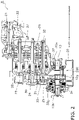
- FIG. 2 is a cross-sectional view of a configuration of the entire transmission 9 according to the present embodiment.
- FIG. 3 is an enlarged view of a portion of FIG. 2 .
- the transmission 9 comprises a housing 20, an input shaft 21, a torque converter 22, a first middle shaft 23, a second middle shaft 24, a third middle shaft 25, and the output shaft 10.
- the input shaft 21, the torque converter 22, the first middle shaft 23, the second middle shaft 24, the third middle shaft 25, and the output shaft 10 transmit the power from the engine 7.
- the housing 20 accommodates the input shaft 21, the torque converter 22, the first middle shaft 23, the second middle shaft 24, the third middle shaft 25, and the output shaft 10.
- the inside of the housing 20 has formed therein an internal space 20R that accommodates the input shaft 21, the torque converter 22, the first middle shaft 23, the second middle shaft 24, the third middle shaft 25, and the output shaft 10. Oil for lubrication is sealed inside the internal space 20R.
- the housing 20 is configured by a conductive material such as a metal.
- the housing 20 is an example of the "housing" according to the present embodiment.
- the output shaft 10 is an example of the "rotating shaft” according to the present embodiment.
- Power from the engine 7 is inputted to the input shaft 21 via the torque converter 22.
- An F-clutch 27 and a first clutch 28 are provided to the first middle shaft 23.
- An R-clutch 29 and a second clutch 30 are provided to the second middle shaft 24.
- a third clutch 31 and a fourth clutch 32 are provided to the third middle shaft 25.
- a transfer shaft 33 is coupled to a front end section of the third middle shaft 25.
- a transfer gear 33g is provided to the transfer shaft 33.
- the output shaft 10 is disposed in the front-back direction. A rear end section of the output shaft 10 protrudes from the housing 20 toward the rear. A front end section of the output shaft 10 protrudes from the housing 20 toward the front. As illustrated in FIG. 3 , the output shaft 10 is supported by the housing 20. The output shaft 10 is rotatable about an axial center AX.
- the output shaft 10 has a rear coupling section 10a and a front coupling section 10b.
- the rear coupling section 10a is connected to a front end section of the rear drive shaft 11.
- the front coupling section 10b is connected to a rear end section of the front drive shaft 14.
- the housing 20 has a housing body 20a, a rearward protruding section 20b, and a forward protruding section 20c (example of a "protruding section").
- the housing body 20a accommodates an axial direction center section of the output shaft 10.
- the axial direction is a direction parallel to the axial center AX of the output shaft 10.
- the rearward protruding section 20b protrudes to the rear from the housing body 20a.
- the rearward protruding section 20b is formed in an annular shape centered on the axial center AX.
- the forward protruding section 20c protrudes to the front from the housing body 20a.
- the forward protruding section 20c is formed in an annular shape centered on the axial center AX.
- a rearward oil seal 35 and a rearward dust seal 36 are disposed in a gap between the rear coupling section 10a of the output shaft 10 and the rearward protruding section 20b of the housing 20.
- the rearward oil seal 35 seals oil inside the housing 20.
- the rearward oil seal 35 is in contact with a surface 10T of the rear coupling section 10a of the rotating shaft 10 and a surface 20T of the rearward protruding section 20b of the housing 20.
- the rearward oil seal 35 is fixed to the surface 20T of the housing 20.
- the rearward oil seal 35 may be fixed also to the surface 10T of the rotating shaft 10.
- the rearward oil seal 35 is disposed on the axial outward side of the housing 20.
- the rearward oil seal 35 is formed in an annular shape centered on the axial center AX. A well-known oil seal may be used for the rearward oil seal 35.
- the axial outward side signifies the rearward protruding section 20b side or the forward protruding section 20c side with respect to the internal space 20R of the housing 20 in the axial direction.
- the axial inward side signifies the internal space 20R side of the housing 20 with respect to the rearward protruding section 20b side or the forward protruding section 20c side in the axial direction.
- the rearward dust seal 36 limits the intrusion to the rearward oil seal 35 side of foreign matter that has intruded into the gap between the output shaft 10 and the rearward protruding section 20b of the housing 20 from the outside.
- the rearward dust seal 36 is in contact with the surface 10T of the rear coupling section 10a of the rotating shaft 10 and the surface 20T of the rearward protruding section 20b of the housing 20.
- the rearward dust seal 36 is disposed on the axial outward side of the rearward oil seal 35.
- the rearward dust seal 36 is formed in an annular shape centered on the axial center AX. A well-known dust seal may be used for the rearward dust seal 36.
- An annular seal cover 37 for covering the axial outward side of the rearward dust seal 36 is attached to the output shaft 10.
- the seal cover 37 limits the intrusion of earth and sand or muddy water or the like (referred to below as “foreign matter") into the gap between the output shaft 10 and the rearward protruding section 20b of the housing 20.
- a forward oil seal 38 and an oil leak detection device 39 are disposed in the gap between the front coupling section 10b of the output shaft 10 and the forward protruding section 20c of the housing 20.
- the forward oil seal 38 seals oil inside the housing 20.
- the forward oil seal 38 is in contact with a surface 10S of the front coupling section 10b of the rotating shaft 10 and a surface 20S of the forward protruding section 20c of the housing 20.
- the forward oil seal 38 is fixed to the surface 20S of the housing 20.
- the forward oil seal 38 may be fixed also to the surface 10S of the rotating shaft 10.
- the forward oil seal 38 is disposed on the axial outward side of the housing 20.
- the forward oil seal 38 is formed in an annular shape centered on the axial center AX. A well-known oil seal may be used for the forward oil seal 38.
- the oil leak detection device 39 detects an oil leak from the forward oil seal 38.
- the oil leak detection device 39 is disposed on the axial outward side of the forward oil seal 38. A configuration of the oil leak detection device 39 is explained below.
- An annular seal cover 40 for covering the axial outward side of the oil leak detection device 39 is attached to the output shaft 10.
- the seal cover 40 limits the intrusion of foreign matter into the gap between the output shaft 10 and the forward protruding section 20c of the housing 20.
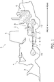
- FIG. 4 is an enlarged view of a portion of FIG. 3 .
- the forward oil seal 38 and the oil leak detection device 39 are mainly illustrated in FIG. 4 .
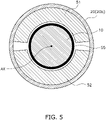
- FIG. 5 is cross-sectional view along line A-A in FIG. 4 .
- FIG. 6 is a cross-sectional view along line B-B in FIG. 4 .
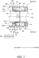
- FIG. 7 is a schematic view corresponding to FIG. 4 and illustrates a state in which an oil leak from the forward oil seal 38 has occurred.
- the oil leak detection device 39 has: a pair of permanent magnets 51, 52; a plurality of commutators 53, 54; a coil 55; a pair of brushes 56, 57; an oil absorbing material 58; dummy commutators 59, 60; a current sensor 61; and a controller 62.
- the pair of permanent magnets 51, 52 are attached to the surface 20S of the forward protruding section 20c within the housing 20.
- the pair of permanent magnets 51, 52 are disposed so that an N-pole and an S-pole face each other.
- the pair of permanent magnets 51, 52 include an N-pole magnet 51 and an S-pole magnet 52 that face each other with the output shaft 10 interposed therebetween.
- the N-pole magnet 51 and the S-pole magnet 52 are separated from each other in the circumferential direction centered on the axial center AX.
- the pair of permanent magnets 51, 52 are disposed on the axial inward side of the plurality of commutators 53, 54; however, the pair of permanent magnets 51, 52 may be disposed on the axial outward side of the plurality of commutators 53, 54.
- the plurality of commutators 53, 54 are attached to the surface 10S of the rotating shaft 10.
- the plurality of commutators 53, 54 face each other with the output shaft 10 interposed therebetween.
- the plurality of commutators 53, 54 are separated from each other in the circumferential direction centered on the axial center AX.
- the plurality of commutators 53, 54 rotate with the rotating shaft 10 around the axial center AX.
- the plurality of commutators 53, 54 that rotate are periodically in contact with the pair of brushes 56, 57.
- the coil 55 is electrically connected to the plurality of commutators 53, 54. In the present embodiment, both ends of the coil 55 are respectively connected to the plurality of commutators 53, 54.
- the coil 55 is disposed on the inside of the pair of permanent magnets 51, 52 in the radial direction centered on the axial center AX.
- the coil 55 is wound onto the rotating shaft 10 on the inside of the pair of permanent magnets 51, 52.
- the number of windings of the coil 55 may be one or more.
- the coil 55 rotates with the rotating shaft 10 around the axial center AX between the pair of permanent magnets 51, 52.
- An induced voltage is produced by electromagnetic induction on the rotating coil 55.
- the induced voltage is produced constantly if the coil 55 is rotating, as explained below, a loop circuit in which the induction current flows is not formed so long as there is no oil leak.
- the coil 55 is also disposed on the axial inward side of the plurality of commutators 53, 54.
- the coil 55 is also disposed on the axial outward side of the plurality of commutators 53, 54.
- the pair of brushes 56, 57 are attached to the surface 20S of the housing 20.
- the pair of brushes 56, 57 face each other with the output shaft 10 interposed therebetween.
- the pair of brushes 56, 57 are separated from each other in the circumferential direction centered on the axial center AX.
- the pair of brushes 56, 57 include a first brush 56 connected to the housing 20 and a second brush 57 separated from the housing 20.
- the first brush 56 is disposed above the rotating shaft 10.
- the second brush 57 is disposed below the rotating shaft 10.
- the first brush 56 is disposed above the axial center AX.
- the second brush 57 is disposed below the axial center AX.
- the pair of brushes 56, 57 are periodically in contact with the plurality of commutators 53, 54 that rotate.
- the pair of brushes 56, 57 are supported by the oil absorbing material 58. Therefore, the pair of brushes 56, 57 are attached to the surface 20S of the housing 20 through the oil absorbing material 58.
- the first brush 56 has a brush body a1 and a conductor a2.
- the brush body a1 is attached to the oil absorbing material 58.
- the conductor a2 is connected to the brush body a1 and the housing 20.
- the conductor a2 is configured by an electrically conductive material.
- the conductor a2 is electrically connected to the brush body a1 and the housing 20.
- the second brush 57 has a brush body a3 and a terminal part a4.
- the brush body a3 is attached to the oil absorbing material 58.
- the terminal part a4 extends from the brush body a3 toward the surface 20S of the housing 20.
- the tip end of the terminal part a4 preferably extends close to the surface 20S of the housing 20.
- the tip end of the terminal part a4 preferably extends close to the tip end of a belowmentioned terminal part b2 of the current sensor 61.
- the oil absorbing material 58 is attached to the surface 20S of the housing 20.
- the oil absorbing material 58 is disposed in a gap between the surface 20S of the housing 20 and the plurality of commutators 53, 54.
- the oil absorbing material 58 absorbs oil that has leaked from the forward oil seal 38.
- the oil absorbing material 58 is configured by a material that has oil absorbency and insulative properties. For example, felt (non-woven fabric) is suitable for such a material.
- the oil absorbing material 58 functions as a supporting member of the pair of brushes 56, 57.
- the oil absorbing material 58 functions as a dust seal. Specifically, the oil absorbing material 58 limits the intrusion, toward the forward oil seal 38, of foreign matter that has intruded into the gap between the rear coupling section 10a of the output shaft 10 and the forward protruding section 20c of the housing 20.
- the dummy commutators 59, 60 are each disposed in a gap between the plurality of commutators 53, 54 in the circumferential direction centered on the axial center AX.
- the dummy commutators 59, 60 limit the intrusion of foreign matter on the axial inward side of the oil leak detection device 39.
- the dummy commutators 59, 60 face each other with the output shaft 10 interposed therebetween.
- the dummy commutators 59, 60 are separated from each other in the circumferential direction centered on the axial center AX.
- the dummy commutators 59, 60 are configured by a material having an insulative property. For example, rubber or felt may be used as such a material. When the dummy commutators 59, 60 are configured by felt, the dummy commutators 59, 60 may be integrated with the oil absorbing material 58.
- the current sensor 61 detects an induction current flowing between the pair of brushes 56, 57 and the forward protruding section 20c of the housing 20 as indicated below. Firstly, as illustrated in FIG. 7 , when an oil leak occurs from the forward oil seal 38 and oil becomes interposed between the second brush 57 and the housing 20, the second brush 57 and the housing 20 are electrically connected by the oil. As a result, a loop circuit is formed by the plurality of commutators 53, 54, the coil 55, the pair of brushes 56, 57, and the housing 20 and an induction current caused by the induced voltage occurring in the coil 55 flows through the loop circuit. The current sensor 61 is activated by the induction current flowing through the loop circuit and detects that an induction current is flowing. The current sensor 61 wirelessly notifies the controller 62 that an induction current has been detected.
- the current sensor 61 has a sensor body b1 and the terminal part b2.
- the sensor body b1 is disposed outside the housing 20.
- the terminal part b2 passes through the housing 20 and extends from the sensor body b1 to the gap between the output shaft 10 and the housing 20.
- the tip end of the terminal part b2 preferably extends close to the surface 20S of the housing 20.
- the tip end of the terminal part b2 preferably close to the tip end of the terminal part a4 of the second brush 57.
- the controller 62 is disposed, for example, in the cab 5.
- the controller 62 issues a warning (warning sound, warning display, etc.) to a worker upon receiving the notification from the current sensor 61 indicating that an induction current has been detected.
- oil seal and the oil leak detection device according to the present disclosure apply to the gap between the output shaft 10 and the housing 20 of the transmission 9 in the above embodiment, the present disclosure is not limited in this way.
- the oil seal and the oil leak detection device according to the present disclosure may also be applied to a gap between the input shaft 21 and the housing 20 of the transmission 9, a gap between the rear drive shaft 11 and the housing of the rear axle 12, a gap between the front drive shaft 14 and the housing of the front axle 15, and the like.
- the second brush 57 has the brush body a3 and the terminal part a4 in the above embodiment, the second brush 57 may not have the terminal part a4.
- the current sensor 61 has the sensor body b1 and the terminal part b2 in the above embodiment, the current sensor 61 may not have the terminal part b2. Even is such a case, the current sensor 61 can detect a current flowing through the housing 20 itself.
Landscapes
- Engineering & Computer Science (AREA)
- General Engineering & Computer Science (AREA)
- Physics & Mathematics (AREA)
- General Physics & Mathematics (AREA)
- Mechanical Engineering (AREA)
- General Details Of Gearings (AREA)
- Examining Or Testing Airtightness (AREA)
- Sealing Devices (AREA)
Abstract
Description
- The present disclosure relates to a power transmission device.
- In a conventional work vehicle, a seal is provided so that oil inside a housing of a power transmission device does not leak out from a gap between the housing and a rotating shaft. The power transmission device is, for example, a transmission or an axle. The rotating shaft is, for example, an output shaft or an input shaft rotatably supported by the housing.
- In Patent Document No. 1, a seal is proposed that has a labyrinth structure configured by inserting together a plurality of fixed-side ring elements attached to the housing and a plurality of rotation-side ring elements attached to the output shaft.
- Patent Document No. 1: Laid-Open Utility Specification No.
63-128320 - However, it is important to quickly detect the occurrence of an oil leakage because it is difficult to completely prevent an oil leak from a gap between a housing and a rotating shaft.
- An object of the present disclosure is to provide a power transmission device with which the occurrence of an oil leak can be detected quickly.
- A power transmission device according to the present disclosure comprises a rotating shaft, a housing that rotatably supports the rotating shaft, an oil seal disposed in a gap between the rotating shaft and the housing, and an oil leak detection device disposed outside of the oil seal in an axial direction parallel to an axial center of the rotating shaft. The oil leak detection device has a pair of permanent magnets with an N-pole and an S-pole facing each other, a plurality of commutators, a coil, a pair of brushes, and a current sensor. The pair of permanent magnets are attached to the housing. The plurality of commutators are attached to the rotating shaft. The coil is wound onto the rotating shaft on an inside of the pair of permanent magnets in a radial direction centered on the axial center of the rotating shaft, and is electrically connected to to the plurality of commutators. The pair of brushes are attached to the housing and are capable of coming into contact with each of the plurality of commutators. The current sensor is configured to detect an induction current flowing between the pair of brushes and the housing.
- According to the present invention, there can be provided a power transmission device with which the occurrence of an oil leak can be detected quickly.
-
-
FIG. 1 is a side view of a wheel loader according to an embodiment. -
FIG. 2 is a cross-sectional view of a transmission according to the embodiment. -
FIG. 3 is an enlarged view of a portion ofFIG. 2 . -
FIG. 4 is an enlarged view of a portion ofFIG. 3 . -
FIG. 5 is a sectional view along line A-A inFIG. 4 . -
FIG. 6 is a sectional view along line B-B inFIG. 4 . -
FIG. 7 is a schematic view illustrating a state in which an oil leak has occurred. -
FIG. 1 is a side view of a wheel loader 1 according to the present embodiment. A power transmission system of the wheel loader 1 is illustrated schematically inFIG. 1 . In the following discussion, "front" and "rear" are the same as "front" and "rear" as seen by an operator seated in the driver's seat. - The wheel loader 1 comprises a
vehicle body 2, a bucket 3, a workimplement drive mechanism 4, and acab 5. Thevehicle body 2 has a front vehicle body and a rear vehicle body. The bucket 3 used for excavating and loading is attached to the front of thevehicle body 2 via the hydraulic workimplement drive mechanism 4. The workimplement drive mechanism 4 is configured by a boom, a bell crank, a coupling link, a bucket cylinder, a boom cylinder, and the like. - The box-
like cab 5 in which the operator rides is disposed on thevehicle body 2. An engine room 6 is provided to a rear end section of thevehicle body 2. Anengine 7 that is a power source is accommodated inside the engine room 6. In the present embodiment, a crankshaft (not illustrated) of theengine 7 is disposed in the front-back direction. - Power of the
engine 7 is transmitted to atransmission 9 via apropeller shaft 8. A portion of the power outputted by thetransmission 9 is transmitted to arear drive shaft 11 via anoutput shaft 10. The power transmitted to therear drive shaft 11 is transmitted to the rear wheels via arear axle 12. A portion of the power outputted by thetransmission 9 is transmitted to afront drive shaft 14 via theoutput shaft 10. The power transmitted to thefront drive shaft 14 is transmitted to the front wheels via afront axle 15. - In the present embodiment, the
transmission 9, theoutput shaft 10, therear drive shaft 11, therear axle 12, thefront drive shaft 14, and thefront axle 15 configure the "power transmission device" according to the present embodiment. -
FIG. 2 is a cross-sectional view of a configuration of theentire transmission 9 according to the present embodiment.FIG. 3 is an enlarged view of a portion ofFIG. 2 . - The
transmission 9 comprises ahousing 20, aninput shaft 21, atorque converter 22, afirst middle shaft 23, asecond middle shaft 24, athird middle shaft 25, and theoutput shaft 10. Theinput shaft 21, thetorque converter 22, thefirst middle shaft 23, thesecond middle shaft 24, thethird middle shaft 25, and theoutput shaft 10 transmit the power from theengine 7. - The
housing 20 accommodates theinput shaft 21, thetorque converter 22, thefirst middle shaft 23, thesecond middle shaft 24, thethird middle shaft 25, and theoutput shaft 10. The inside of thehousing 20 has formed therein aninternal space 20R that accommodates theinput shaft 21, thetorque converter 22, thefirst middle shaft 23, thesecond middle shaft 24, thethird middle shaft 25, and theoutput shaft 10. Oil for lubrication is sealed inside theinternal space 20R. Thehousing 20 is configured by a conductive material such as a metal. Thehousing 20 is an example of the "housing" according to the present embodiment. Theoutput shaft 10 is an example of the "rotating shaft" according to the present embodiment. - Power from the
engine 7 is inputted to theinput shaft 21 via thetorque converter 22. An F-clutch 27 and afirst clutch 28 are provided to thefirst middle shaft 23. An R-clutch 29 and asecond clutch 30 are provided to thesecond middle shaft 24. Athird clutch 31 and afourth clutch 32 are provided to thethird middle shaft 25. Atransfer shaft 33 is coupled to a front end section of thethird middle shaft 25. Atransfer gear 33g is provided to thetransfer shaft 33. - Power from the
transfer shaft 33 is transmitted to theoutput shaft 10. Anoutput gear 10g that meshes with thetransfer gear 33g, and aparking brake 34 are provided to theoutput shaft 10. - The
output shaft 10 is disposed in the front-back direction. A rear end section of theoutput shaft 10 protrudes from thehousing 20 toward the rear. A front end section of theoutput shaft 10 protrudes from thehousing 20 toward the front. As illustrated inFIG. 3 , theoutput shaft 10 is supported by thehousing 20. Theoutput shaft 10 is rotatable about an axial center AX. - As illustrated in
FIG. 3 , theoutput shaft 10 has arear coupling section 10a and afront coupling section 10b. Therear coupling section 10a is connected to a front end section of therear drive shaft 11. Thefront coupling section 10b is connected to a rear end section of thefront drive shaft 14. - As illustrated in
FIG. 3 , thehousing 20 has ahousing body 20a, a rearward protrudingsection 20b, and a forward protrudingsection 20c (example of a "protruding section"). Thehousing body 20a accommodates an axial direction center section of theoutput shaft 10. The axial direction is a direction parallel to the axial center AX of theoutput shaft 10. The rearward protrudingsection 20b protrudes to the rear from thehousing body 20a. The rearward protrudingsection 20b is formed in an annular shape centered on the axial center AX. The forward protrudingsection 20c protrudes to the front from thehousing body 20a. The forward protrudingsection 20c is formed in an annular shape centered on the axial center AX. - A
rearward oil seal 35 and arearward dust seal 36 are disposed in a gap between therear coupling section 10a of theoutput shaft 10 and the rearward protrudingsection 20b of thehousing 20. - The
rearward oil seal 35 seals oil inside thehousing 20. Therearward oil seal 35 is in contact with asurface 10T of therear coupling section 10a of therotating shaft 10 and asurface 20T of the rearward protrudingsection 20b of thehousing 20. Therearward oil seal 35 is fixed to thesurface 20T of thehousing 20. Therearward oil seal 35 may be fixed also to thesurface 10T of therotating shaft 10. Therearward oil seal 35 is disposed on the axial outward side of thehousing 20. Therearward oil seal 35 is formed in an annular shape centered on the axial center AX. A well-known oil seal may be used for therearward oil seal 35. - In the present embodiment, the axial outward side signifies the rearward protruding
section 20b side or the forward protrudingsection 20c side with respect to theinternal space 20R of thehousing 20 in the axial direction. Additionally, in the present embodiment, the axial inward side signifies theinternal space 20R side of thehousing 20 with respect to the rearward protrudingsection 20b side or the forward protrudingsection 20c side in the axial direction. - The
rearward dust seal 36 limits the intrusion to therearward oil seal 35 side of foreign matter that has intruded into the gap between theoutput shaft 10 and the rearward protrudingsection 20b of thehousing 20 from the outside. Therearward dust seal 36 is in contact with thesurface 10T of therear coupling section 10a of therotating shaft 10 and thesurface 20T of the rearward protrudingsection 20b of thehousing 20. Therearward dust seal 36 is disposed on the axial outward side of therearward oil seal 35. Therearward dust seal 36 is formed in an annular shape centered on the axial center AX. A well-known dust seal may be used for therearward dust seal 36. - An
annular seal cover 37 for covering the axial outward side of therearward dust seal 36 is attached to theoutput shaft 10. The seal cover 37 limits the intrusion of earth and sand or muddy water or the like (referred to below as "foreign matter") into the gap between theoutput shaft 10 and the rearward protrudingsection 20b of thehousing 20. - A
forward oil seal 38 and an oilleak detection device 39 are disposed in the gap between thefront coupling section 10b of theoutput shaft 10 and the forward protrudingsection 20c of thehousing 20. - The
forward oil seal 38 seals oil inside thehousing 20. Theforward oil seal 38 is in contact with asurface 10S of thefront coupling section 10b of therotating shaft 10 and asurface 20S of the forward protrudingsection 20c of thehousing 20. Theforward oil seal 38 is fixed to thesurface 20S of thehousing 20. Theforward oil seal 38 may be fixed also to thesurface 10S of therotating shaft 10. Theforward oil seal 38 is disposed on the axial outward side of thehousing 20. Theforward oil seal 38 is formed in an annular shape centered on the axial center AX. A well-known oil seal may be used for theforward oil seal 38. - The oil
leak detection device 39 detects an oil leak from theforward oil seal 38. The oilleak detection device 39 is disposed on the axial outward side of theforward oil seal 38. A configuration of the oilleak detection device 39 is explained below. - An
annular seal cover 40 for covering the axial outward side of the oilleak detection device 39 is attached to theoutput shaft 10. The seal cover 40 limits the intrusion of foreign matter into the gap between theoutput shaft 10 and the forward protrudingsection 20c of thehousing 20. -
FIG. 4 is an enlarged view of a portion ofFIG. 3 . Theforward oil seal 38 and the oilleak detection device 39 are mainly illustrated inFIG. 4 .FIG. 5 is cross-sectional view along line A-A inFIG. 4 .FIG. 6 is a cross-sectional view along line B-B inFIG. 4 .FIG. 7 is a schematic view corresponding toFIG. 4 and illustrates a state in which an oil leak from theforward oil seal 38 has occurred. - The oil
leak detection device 39 has: a pair ofpermanent magnets commutators coil 55; a pair ofbrushes oil absorbing material 58;dummy commutators current sensor 61; and acontroller 62. - The pair of
permanent magnets surface 20S of the forward protrudingsection 20c within thehousing 20. The pair ofpermanent magnets permanent magnets pole magnet 51 and an S-pole magnet 52 that face each other with theoutput shaft 10 interposed therebetween. The N-pole magnet 51 and the S-pole magnet 52 are separated from each other in the circumferential direction centered on the axial center AX. - In the present embodiment, the pair of
permanent magnets commutators permanent magnets commutators - The plurality of
commutators surface 10S of therotating shaft 10. The plurality ofcommutators output shaft 10 interposed therebetween. The plurality ofcommutators commutators shaft 10 around the axial center AX. The plurality ofcommutators brushes - The
coil 55 is electrically connected to the plurality ofcommutators coil 55 are respectively connected to the plurality ofcommutators coil 55 is disposed on the inside of the pair ofpermanent magnets coil 55 is wound onto the rotatingshaft 10 on the inside of the pair ofpermanent magnets coil 55 may be one or more. - The
coil 55 rotates with the rotatingshaft 10 around the axial center AX between the pair ofpermanent magnets coil 55. However, while the induced voltage is produced constantly if thecoil 55 is rotating, as explained below, a loop circuit in which the induction current flows is not formed so long as there is no oil leak. - In the present embodiment, because the pair of
permanent magnets commutators coil 55 is also disposed on the axial inward side of the plurality ofcommutators permanent magnets commutators coil 55 is also disposed on the axial outward side of the plurality ofcommutators - The pair of
brushes surface 20S of thehousing 20. The pair ofbrushes output shaft 10 interposed therebetween. The pair ofbrushes brushes first brush 56 connected to thehousing 20 and asecond brush 57 separated from thehousing 20. Thefirst brush 56 is disposed above the rotatingshaft 10. Thesecond brush 57 is disposed below the rotatingshaft 10. Thefirst brush 56 is disposed above the axial center AX. Thesecond brush 57 is disposed below the axial center AX. The pair ofbrushes commutators - In the present embodiment, the pair of
brushes oil absorbing material 58. Therefore, the pair ofbrushes surface 20S of thehousing 20 through theoil absorbing material 58. - In the present embodiment, the
first brush 56 has a brush body a1 and a conductor a2. The brush body a1 is attached to theoil absorbing material 58. The conductor a2 is connected to the brush body a1 and thehousing 20. The conductor a2 is configured by an electrically conductive material. The conductor a2 is electrically connected to the brush body a1 and thehousing 20. - In the present embodiment, the
second brush 57 has a brush body a3 and a terminal part a4. The brush body a3 is attached to theoil absorbing material 58. The terminal part a4 extends from the brush body a3 toward thesurface 20S of thehousing 20. The tip end of the terminal part a4 preferably extends close to thesurface 20S of thehousing 20. The tip end of the terminal part a4 preferably extends close to the tip end of a belowmentioned terminal part b2 of thecurrent sensor 61. - The
oil absorbing material 58 is attached to thesurface 20S of thehousing 20. Theoil absorbing material 58 is disposed in a gap between thesurface 20S of thehousing 20 and the plurality ofcommutators oil absorbing material 58 absorbs oil that has leaked from theforward oil seal 38. Theoil absorbing material 58 is configured by a material that has oil absorbency and insulative properties. For example, felt (non-woven fabric) is suitable for such a material. - In the present embodiment, the
oil absorbing material 58 functions as a supporting member of the pair ofbrushes oil absorbing material 58 functions as a dust seal. Specifically, theoil absorbing material 58 limits the intrusion, toward theforward oil seal 38, of foreign matter that has intruded into the gap between therear coupling section 10a of theoutput shaft 10 and the forward protrudingsection 20c of thehousing 20. - The dummy commutators 59, 60 are each disposed in a gap between the plurality of
commutators leak detection device 39. The dummy commutators 59, 60 face each other with theoutput shaft 10 interposed therebetween. The dummy commutators 59, 60 are separated from each other in the circumferential direction centered on the axial center AX. The dummy commutators 59, 60 are configured by a material having an insulative property. For example, rubber or felt may be used as such a material. When thedummy commutators dummy commutators oil absorbing material 58. - The
current sensor 61 detects an induction current flowing between the pair ofbrushes section 20c of thehousing 20 as indicated below. Firstly, as illustrated inFIG. 7 , when an oil leak occurs from theforward oil seal 38 and oil becomes interposed between thesecond brush 57 and thehousing 20, thesecond brush 57 and thehousing 20 are electrically connected by the oil. As a result, a loop circuit is formed by the plurality ofcommutators coil 55, the pair ofbrushes housing 20 and an induction current caused by the induced voltage occurring in thecoil 55 flows through the loop circuit. Thecurrent sensor 61 is activated by the induction current flowing through the loop circuit and detects that an induction current is flowing. Thecurrent sensor 61 wirelessly notifies thecontroller 62 that an induction current has been detected. - In the present embodiment, the
current sensor 61 has a sensor body b1 and the terminal part b2. The sensor body b1 is disposed outside thehousing 20. The terminal part b2 passes through thehousing 20 and extends from the sensor body b1 to the gap between theoutput shaft 10 and thehousing 20. The tip end of the terminal part b2 preferably extends close to thesurface 20S of thehousing 20. The tip end of the terminal part b2 preferably close to the tip end of the terminal part a4 of thesecond brush 57. - The
controller 62 is disposed, for example, in thecab 5. Thecontroller 62 issues a warning (warning sound, warning display, etc.) to a worker upon receiving the notification from thecurrent sensor 61 indicating that an induction current has been detected. -
- (1) The
transmission 9 comprises theoutput shaft 10, thehousing 20, theforward oil seal 38, and the oilleak detection device 39. Thehousing 20 rotatably supports theoutput shaft 10. Theforward oil seal 38 is disposed in a gap between theoutput shaft 10 and thehousing 20. The oilleak detection device 39 is disposed on the axial outward side of theforward oil seal 38. The oilleak detection device 39 has: the pair ofpermanent magnets commutators coil 55; the pair ofbrushes current sensor 61. The N-pole and the S-pole of the pair ofpermanent magnets commutators output shaft 10. Thecoil 55 is wound around theoutput shaft 10 inside the pair ofpermanent magnets output shaft 10. Thecoil 55 is electrically connected to the plurality ofcommutators brushes housing 20 and are able to come into contact with each of the plurality ofcommutators current sensor 61 detects an induction current flowing between the pair ofbrushes housing 20.
Therefore, thecurrent sensor 61 detects the induction current flowing through the loop circuit formed by the plurality ofcommutators coil 55, the pair ofbrushes housing 20 when an oil leak from theforward oil seal 38 occurs and thesecond brush 57 and thehousing 20 are electrically connected by the oil. Accordingly, the occurrence of the oil leak can be detected quickly. - (2) The pair of
brushes first brush 56 connected to thehousing 20 and thesecond brush 57 separated from thehousing 20. Thesecond brush 57 has the brush body a3 and the terminal part a4 that extends from the brush body a3 toward thehousing 20. Accordingly, the loop circuit can be formed quickly by oil that has leaked along thesurface 20S of thehousing 20 coming into contact with thesecond brush 57. - (3) The
first brush 56 is disposed above theoutput shaft 10 and thesecond brush 57 is disposed below theoutput shaft 10. Accordingly, thesecond brush 57 is able to quickly make contact with the oil that has leaked along a lower part of thesurface 20S of thehousing 20. - (4) The
current sensor 61 has the sensor body b1 that is disposed outside of thehousing 20, and the terminal part b2 that extends from the sensor body b1 to the inside of thehousing 20. Accordingly, thecurrent sensor 61 is able to quickly make contact with the oil that has leaked along thesurface 20S of thehousing 20. - (5) The
current sensor 61 is activated by the induction current flowing between the pair of brushes and the housing. Accordingly, the configuration of the oilleak detection device 39 is further simplified because there is no need for a power source for thecurrent sensor 61. - (6) The
current sensor 61 wirelessly notifies thecontroller 62 that an induction current has been detected. Accordingly, the configuration of the oilleak detection device 39 can be further simplified in comparison to when thecurrent sensor 61 and thecontroller 62 are connected by wire. - (7) The pair of
brushes housing 20 via the insulativeoil absorbing material 58. Accordingly, delaying of the oil leak and the intrusion of foreign matter from the outside through the gap between the plurality ofcommutators housing 20 can be suppressed. - (8) The oil
leak detection device 39 has thedummy commutators commutators commutators - The present invention is not limited to the above embodiment and various changes and modifications may be made without departing from the spirit of the invention.
- While the oil seal and the oil leak detection device according to the present disclosure apply to the gap between the
output shaft 10 and thehousing 20 of thetransmission 9 in the above embodiment, the present disclosure is not limited in this way. The oil seal and the oil leak detection device according to the present disclosure may also be applied to a gap between theinput shaft 21 and thehousing 20 of thetransmission 9, a gap between therear drive shaft 11 and the housing of therear axle 12, a gap between thefront drive shaft 14 and the housing of thefront axle 15, and the like. - While the
second brush 57 has the brush body a3 and the terminal part a4 in the above embodiment, thesecond brush 57 may not have the terminal part a4. - While the
current sensor 61 has the sensor body b1 and the terminal part b2 in the above embodiment, thecurrent sensor 61 may not have the terminal part b2. Even is such a case, thecurrent sensor 61 can detect a current flowing through thehousing 20 itself. -
- 1:
- Wheel loader
- 9:
- Transmission
- 10:
- Output shaft
- 11:
- Rear drive shaft
- 12:
- Rear axle
- 14:
- Front drive shaft
- 15:
- Front axle
- 20:
- Housing
- 20a:
- Housing body
- 20b:
- Rear protruding section
- 35:
- Rear oil seal
- 36:
- Rear dust seal
- 37:
- Seal cover
- 38:
- Front oil seal
- 39:
- Oil leak detection device
- 40:
- Seal cover
- 51, 52:
- Pair of permanent magnet
- 53, 54:
- Plurality of commutators
- 55:
- Coil
- 56, 57:
- Pair of brushes
- 56:
- First brush
- a1:
- Brush body
- a2:
- Conductor
- 57:
- Second brush
- a3:
- Brush body
- a4:
- Terminal part
- 58:
- Oil absorbing material
- 59, 60:
- Dummy commutator
- 61:
- Current sensor
- 62:
- Controller
Claims (8)
- A power transmission device comprising:a rotating shaft;a housing rotatably supporting the rotating shaft;an oil seal disposed in a gap between the rotating shaft and the housing; andan oil leak detection device disposed outside of the oil seal in an axial direction parallel to an axial center of the rotating shaft,whereinthe oil leak detection device has:a pair of permanent magnets attached to the housing and having an N-pole and an S-pole that face each other;a plurality of commutators attached to the rotating shaft;a coil wound onto the rotating shaft on an inside of the pair of permanent magnets in a radial direction centered on the axial center of the rotating shaft, and electrically connected to the plurality of commutators;a pair of brushes that are attached to the housing and capable of coming into contact with each of the plurality of commutators; anda current sensor configured to detect an induction current flowing between the pair of brushes and the housing.
- The power transmission device according to claim 1, whereinthe pair of brushes include a first brush connected to the housing, and a second brush separated from the housing, andthe second brush has a brush body and a terminal part that extends from the brush body toward the housing.
- The power transmission device according to claim 2, whereinthe first brush is disposed above the rotating shaft, andthe second brush is disposed below the rotating shaft.
- The power transmission device according to any one of claims 1 to 3, wherein
the current sensor has a sensor body disposed outside of the housing and a terminal part that extends from the sensor body to the gap. - The power transmission device according to any one of claims 1 to 4, wherein
the current sensor is activated by the induction current. - The power transmission device according to any one of claims 1 to 5, wherein
the current sensor wirelessly notifies a controller that the induction current has been detected. - The power transmission device according to any one of claims 1 to 6, wherein
the pair of brushes are attached to the housing through an insulative oil absorbing material. - The power transmission device according to any one of claims 1 to 7, wherein
the oil leak detection device has a dummy commutator disposed in a gap between the plurality of commutators in a circumferential direction centered on the axial center.
Applications Claiming Priority (2)
| Application Number | Priority Date | Filing Date | Title |
|---|---|---|---|
| JP2020037676A JP7432397B2 (en) | 2020-03-05 | 2020-03-05 | power transmission device |
| PCT/JP2021/000265 WO2021176835A1 (en) | 2020-03-05 | 2021-01-07 | Power transmission device |
Publications (3)
| Publication Number | Publication Date |
|---|---|
| EP4056979A1 true EP4056979A1 (en) | 2022-09-14 |
| EP4056979A4 EP4056979A4 (en) | 2023-01-18 |
| EP4056979B1 EP4056979B1 (en) | 2024-10-30 |
Family
ID=77613607
Family Applications (1)
| Application Number | Title | Priority Date | Filing Date |
|---|---|---|---|
| EP21763490.6A Active EP4056979B1 (en) | 2020-03-05 | 2021-01-07 | Power transmission device |
Country Status (5)
| Country | Link |
|---|---|
| US (1) | US12253435B2 (en) |
| EP (1) | EP4056979B1 (en) |
| JP (1) | JP7432397B2 (en) |
| CN (1) | CN114867957A (en) |
| WO (1) | WO2021176835A1 (en) |
Family Cites Families (18)
| Publication number | Priority date | Publication date | Assignee | Title |
|---|---|---|---|---|
| JPS62298737A (en) * | 1986-06-18 | 1987-12-25 | Chiyoda Chem Eng & Constr Co Ltd | Piping leak detection measurement method |
| JPS63128320A (en) | 1986-11-19 | 1988-05-31 | Minolta Camera Co Ltd | Camera using ic card |
| JPH0443643Y2 (en) | 1987-02-14 | 1992-10-15 | ||
| US6592126B2 (en) | 2001-07-20 | 2003-07-15 | Flowserve Management Company | Mechanical seal leak detector |
| DE102005036338A1 (en) | 2005-07-29 | 2007-02-15 | Wilo Ag | Mechanical seal |
| US7692553B2 (en) * | 2006-07-21 | 2010-04-06 | Deublin Company | Leak detecting system for rotating union |
| WO2008120399A1 (en) * | 2007-04-03 | 2008-10-09 | Nok Corporation | Hermetic closure structure |
| JP2011214593A (en) * | 2010-03-31 | 2011-10-27 | Mazda Motor Corp | Power transmission device |
| JP2012117551A (en) * | 2010-11-29 | 2012-06-21 | Ogura Clutch Co Ltd | Electromagnetic clutch |
| EP2686656B1 (en) * | 2011-03-14 | 2018-10-10 | Aktiebolaget SKF | Sensorized sealing system |
| KR101648642B1 (en) * | 2014-03-27 | 2016-08-23 | 이희장 | Sealing system having function for sensing leakage |
| DE102014210129A1 (en) | 2014-05-27 | 2015-12-03 | Aktiebolaget Skf | Sealing device and method for sealing in a liquid medium |
| CN107430090B (en) | 2015-03-11 | 2020-06-23 | 三菱电机株式会社 | Rope damage diagnosis and inspection device and rope damage diagnosis and inspection method |
| JP6756594B2 (en) * | 2016-12-06 | 2020-09-16 | 株式会社小松製作所 | Link assembly and seal assembly |
| CN109115431A (en) | 2018-09-30 | 2019-01-01 | 广州市和晋自动化控制技术有限公司 | A kind of air-liquid body soft packaging bag vacuum leak detector and leak hunting method |
| CN111262378B (en) * | 2020-03-17 | 2021-11-30 | Abb瑞士股份有限公司 | Motor and industrial robot |
| EP4214427B1 (en) * | 2020-09-18 | 2026-03-25 | Abb Schweiz Ag | Apparatus for determining oil leakage and robot using the apparatus |
| CN116348751B (en) * | 2020-09-21 | 2025-04-08 | Abb瑞士股份有限公司 | Device for determining oil leakage and robot using the same |
-
2020
- 2020-03-05 JP JP2020037676A patent/JP7432397B2/en active Active
-
2021
- 2021-01-07 CN CN202180007241.7A patent/CN114867957A/en active Pending
- 2021-01-07 US US17/788,016 patent/US12253435B2/en active Active
- 2021-01-07 EP EP21763490.6A patent/EP4056979B1/en active Active
- 2021-01-07 WO PCT/JP2021/000265 patent/WO2021176835A1/en not_active Ceased
Also Published As
| Publication number | Publication date |
|---|---|
| CN114867957A (en) | 2022-08-05 |
| JP7432397B2 (en) | 2024-02-16 |
| WO2021176835A1 (en) | 2021-09-10 |
| US12253435B2 (en) | 2025-03-18 |
| US20230026073A1 (en) | 2023-01-26 |
| EP4056979B1 (en) | 2024-10-30 |
| JP2021139751A (en) | 2021-09-16 |
| EP4056979A4 (en) | 2023-01-18 |
Similar Documents
| Publication | Publication Date | Title |
|---|---|---|
| US5296805A (en) | Serviceable wheel speed sensor with magnet assisted retention | |
| EP1666777A1 (en) | Sealing device | |
| CN102822011B (en) | Rotary connector unit | |
| JP6220724B2 (en) | Power transmission device for vehicle | |
| WO2009157274A1 (en) | Bearing seal | |
| KR20030051310A (en) | Vehicle mounted bearing assembly | |
| CN106253590B (en) | For winding the slip ring of rotor synchronous motor and the structure of brush | |
| EP4056979B1 (en) | Power transmission device | |
| US7232129B2 (en) | Sealing apparatus with encoder | |
| WO2023008181A1 (en) | Sealing device | |
| EP1433621A2 (en) | Rolling bearing apparatus with sensor | |
| WO2012039156A1 (en) | Oil seal | |
| GB2482704A (en) | Sealing arrangement for an electric motor or generator | |
| US7336067B2 (en) | Sensor assembly, sealing device, and roller bearing apparatus for vehicles having integrated connector and ring | |
| JP2003187368A (en) | Vehicle bearing device | |
| WO2018062417A1 (en) | Power transmission device | |
| JP4544401B2 (en) | Sealing device | |
| CN117501036A (en) | Sealing structure for hub motor drive system and hub motor drive system | |
| JP2008267423A (en) | Bearing seal | |
| WO2021152082A1 (en) | Instrumented bearing incorporating a leakage current collector and a magnetic shield | |
| JP2005042817A (en) | Sealing device with encoder | |
| CN211456889U (en) | A junction box for electric wheel hub motor | |
| JP2007327645A (en) | Bearing device for vehicle | |
| CN222458156U (en) | A parallel structure elastic coupling with adjustable axial size | |
| JP4258214B2 (en) | Rolling bearing device |
Legal Events
| Date | Code | Title | Description |
|---|---|---|---|
| STAA | Information on the status of an ep patent application or granted ep patent |
Free format text: STATUS: THE INTERNATIONAL PUBLICATION HAS BEEN MADE |
|
| PUAI | Public reference made under article 153(3) epc to a published international application that has entered the european phase |
Free format text: ORIGINAL CODE: 0009012 |
|
| STAA | Information on the status of an ep patent application or granted ep patent |
Free format text: STATUS: REQUEST FOR EXAMINATION WAS MADE |
|
| 17P | Request for examination filed |
Effective date: 20220608 |
|
| AK | Designated contracting states |
Kind code of ref document: A1 Designated state(s): AL AT BE BG CH CY CZ DE DK EE ES FI FR GB GR HR HU IE IS IT LI LT LU LV MC MK MT NL NO PL PT RO RS SE SI SK SM TR |
|
| REG | Reference to a national code |
Ref country code: DE Free format text: PREVIOUS MAIN CLASS: G01M0003400000 Ref country code: DE Ref legal event code: R079 Ref document number: 602021021066 Country of ref document: DE Free format text: PREVIOUS MAIN CLASS: G01M0003400000 Ipc: F16J0015329600 |
|
| A4 | Supplementary search report drawn up and despatched |
Effective date: 20221220 |
|
| RIC1 | Information provided on ipc code assigned before grant |
Ipc: G01M 3/02 20060101ALI20221215BHEP Ipc: G01M 3/18 20060101ALI20221215BHEP Ipc: F16J 15/3296 20160101AFI20221215BHEP |
|
| DAV | Request for validation of the european patent (deleted) | ||
| DAX | Request for extension of the european patent (deleted) | ||
| GRAP | Despatch of communication of intention to grant a patent |
Free format text: ORIGINAL CODE: EPIDOSNIGR1 |
|
| STAA | Information on the status of an ep patent application or granted ep patent |
Free format text: STATUS: GRANT OF PATENT IS INTENDED |
|
| RIC1 | Information provided on ipc code assigned before grant |
Ipc: G01M 3/02 20060101ALI20231214BHEP Ipc: G01M 3/18 20060101ALI20231214BHEP Ipc: F16J 15/3296 20160101AFI20231214BHEP |
|
| INTG | Intention to grant announced |
Effective date: 20240117 |
|
| GRAJ | Information related to disapproval of communication of intention to grant by the applicant or resumption of examination proceedings by the epo deleted |
Free format text: ORIGINAL CODE: EPIDOSDIGR1 |
|
| STAA | Information on the status of an ep patent application or granted ep patent |
Free format text: STATUS: REQUEST FOR EXAMINATION WAS MADE |
|
| GRAP | Despatch of communication of intention to grant a patent |
Free format text: ORIGINAL CODE: EPIDOSNIGR1 |
|
| STAA | Information on the status of an ep patent application or granted ep patent |
Free format text: STATUS: GRANT OF PATENT IS INTENDED |
|
| INTC | Intention to grant announced (deleted) | ||
| INTG | Intention to grant announced |
Effective date: 20240524 |
|
| GRAS | Grant fee paid |
Free format text: ORIGINAL CODE: EPIDOSNIGR3 |
|
| GRAA | (expected) grant |
Free format text: ORIGINAL CODE: 0009210 |
|
| STAA | Information on the status of an ep patent application or granted ep patent |
Free format text: STATUS: THE PATENT HAS BEEN GRANTED |
|
| AK | Designated contracting states |
Kind code of ref document: B1 Designated state(s): AL AT BE BG CH CY CZ DE DK EE ES FI FR GB GR HR HU IE IS IT LI LT LU LV MC MK MT NL NO PL PT RO RS SE SI SK SM TR |
|
| REG | Reference to a national code |
Ref country code: GB Ref legal event code: FG4D |
|
| REG | Reference to a national code |
Ref country code: CH Ref legal event code: EP |
|
| REG | Reference to a national code |
Ref country code: DE Ref legal event code: R096 Ref document number: 602021021066 Country of ref document: DE |
|
| REG | Reference to a national code |
Ref country code: IE Ref legal event code: FG4D |
|
| REG | Reference to a national code |
Ref country code: SE Ref legal event code: TRGR |
|
| REG | Reference to a national code |
Ref country code: LT Ref legal event code: MG9D |
|
| REG | Reference to a national code |
Ref country code: NL Ref legal event code: MP Effective date: 20241030 |
|
| PG25 | Lapsed in a contracting state [announced via postgrant information from national office to epo] |
Ref country code: PT Free format text: LAPSE BECAUSE OF FAILURE TO SUBMIT A TRANSLATION OF THE DESCRIPTION OR TO PAY THE FEE WITHIN THE PRESCRIBED TIME-LIMIT Effective date: 20250228 Ref country code: IS Free format text: LAPSE BECAUSE OF FAILURE TO SUBMIT A TRANSLATION OF THE DESCRIPTION OR TO PAY THE FEE WITHIN THE PRESCRIBED TIME-LIMIT Effective date: 20250228 Ref country code: HR Free format text: LAPSE BECAUSE OF FAILURE TO SUBMIT A TRANSLATION OF THE DESCRIPTION OR TO PAY THE FEE WITHIN THE PRESCRIBED TIME-LIMIT Effective date: 20241030 |
|
| PGFP | Annual fee paid to national office [announced via postgrant information from national office to epo] |
Ref country code: DE Payment date: 20250210 Year of fee payment: 5 |
|
| PG25 | Lapsed in a contracting state [announced via postgrant information from national office to epo] |
Ref country code: NL Free format text: LAPSE BECAUSE OF FAILURE TO SUBMIT A TRANSLATION OF THE DESCRIPTION OR TO PAY THE FEE WITHIN THE PRESCRIBED TIME-LIMIT Effective date: 20241030 Ref country code: FI Free format text: LAPSE BECAUSE OF FAILURE TO SUBMIT A TRANSLATION OF THE DESCRIPTION OR TO PAY THE FEE WITHIN THE PRESCRIBED TIME-LIMIT Effective date: 20241030 |
|
| REG | Reference to a national code |
Ref country code: AT Ref legal event code: MK05 Ref document number: 1737155 Country of ref document: AT Kind code of ref document: T Effective date: 20241030 |
|
| PG25 | Lapsed in a contracting state [announced via postgrant information from national office to epo] |
Ref country code: BG Free format text: LAPSE BECAUSE OF FAILURE TO SUBMIT A TRANSLATION OF THE DESCRIPTION OR TO PAY THE FEE WITHIN THE PRESCRIBED TIME-LIMIT Effective date: 20241030 |
|
| PG25 | Lapsed in a contracting state [announced via postgrant information from national office to epo] |
Ref country code: ES Free format text: LAPSE BECAUSE OF FAILURE TO SUBMIT A TRANSLATION OF THE DESCRIPTION OR TO PAY THE FEE WITHIN THE PRESCRIBED TIME-LIMIT Effective date: 20241030 |
|
| PGFP | Annual fee paid to national office [announced via postgrant information from national office to epo] |
Ref country code: SE Payment date: 20250122 Year of fee payment: 5 |
|
| PG25 | Lapsed in a contracting state [announced via postgrant information from national office to epo] |
Ref country code: NO Free format text: LAPSE BECAUSE OF FAILURE TO SUBMIT A TRANSLATION OF THE DESCRIPTION OR TO PAY THE FEE WITHIN THE PRESCRIBED TIME-LIMIT Effective date: 20250130 |
|
| PG25 | Lapsed in a contracting state [announced via postgrant information from national office to epo] |
Ref country code: AT Free format text: LAPSE BECAUSE OF FAILURE TO SUBMIT A TRANSLATION OF THE DESCRIPTION OR TO PAY THE FEE WITHIN THE PRESCRIBED TIME-LIMIT Effective date: 20241030 Ref country code: LV Free format text: LAPSE BECAUSE OF FAILURE TO SUBMIT A TRANSLATION OF THE DESCRIPTION OR TO PAY THE FEE WITHIN THE PRESCRIBED TIME-LIMIT Effective date: 20241030 Ref country code: GR Free format text: LAPSE BECAUSE OF FAILURE TO SUBMIT A TRANSLATION OF THE DESCRIPTION OR TO PAY THE FEE WITHIN THE PRESCRIBED TIME-LIMIT Effective date: 20250131 |
|
| PG25 | Lapsed in a contracting state [announced via postgrant information from national office to epo] |
Ref country code: PL Free format text: LAPSE BECAUSE OF FAILURE TO SUBMIT A TRANSLATION OF THE DESCRIPTION OR TO PAY THE FEE WITHIN THE PRESCRIBED TIME-LIMIT Effective date: 20241030 |
|
| PG25 | Lapsed in a contracting state [announced via postgrant information from national office to epo] |
Ref country code: RS Free format text: LAPSE BECAUSE OF FAILURE TO SUBMIT A TRANSLATION OF THE DESCRIPTION OR TO PAY THE FEE WITHIN THE PRESCRIBED TIME-LIMIT Effective date: 20250130 |
|
| PG25 | Lapsed in a contracting state [announced via postgrant information from national office to epo] |
Ref country code: SM Free format text: LAPSE BECAUSE OF FAILURE TO SUBMIT A TRANSLATION OF THE DESCRIPTION OR TO PAY THE FEE WITHIN THE PRESCRIBED TIME-LIMIT Effective date: 20241030 |
|
| PG25 | Lapsed in a contracting state [announced via postgrant information from national office to epo] |
Ref country code: DK Free format text: LAPSE BECAUSE OF FAILURE TO SUBMIT A TRANSLATION OF THE DESCRIPTION OR TO PAY THE FEE WITHIN THE PRESCRIBED TIME-LIMIT Effective date: 20241030 |
|
| PG25 | Lapsed in a contracting state [announced via postgrant information from national office to epo] |
Ref country code: EE Free format text: LAPSE BECAUSE OF FAILURE TO SUBMIT A TRANSLATION OF THE DESCRIPTION OR TO PAY THE FEE WITHIN THE PRESCRIBED TIME-LIMIT Effective date: 20241030 |
|
| PG25 | Lapsed in a contracting state [announced via postgrant information from national office to epo] |
Ref country code: RO Free format text: LAPSE BECAUSE OF FAILURE TO SUBMIT A TRANSLATION OF THE DESCRIPTION OR TO PAY THE FEE WITHIN THE PRESCRIBED TIME-LIMIT Effective date: 20241030 |
|
| PG25 | Lapsed in a contracting state [announced via postgrant information from national office to epo] |
Ref country code: SK Free format text: LAPSE BECAUSE OF FAILURE TO SUBMIT A TRANSLATION OF THE DESCRIPTION OR TO PAY THE FEE WITHIN THE PRESCRIBED TIME-LIMIT Effective date: 20241030 |
|
| PG25 | Lapsed in a contracting state [announced via postgrant information from national office to epo] |
Ref country code: CZ Free format text: LAPSE BECAUSE OF FAILURE TO SUBMIT A TRANSLATION OF THE DESCRIPTION OR TO PAY THE FEE WITHIN THE PRESCRIBED TIME-LIMIT Effective date: 20241030 |
|
| PG25 | Lapsed in a contracting state [announced via postgrant information from national office to epo] |
Ref country code: IT Free format text: LAPSE BECAUSE OF FAILURE TO SUBMIT A TRANSLATION OF THE DESCRIPTION OR TO PAY THE FEE WITHIN THE PRESCRIBED TIME-LIMIT Effective date: 20241030 |
|
| REG | Reference to a national code |
Ref country code: DE Ref legal event code: R097 Ref document number: 602021021066 Country of ref document: DE |
|
| REG | Reference to a national code |
Ref country code: CH Ref legal event code: PL |
|
| PLBE | No opposition filed within time limit |
Free format text: ORIGINAL CODE: 0009261 |
|
| STAA | Information on the status of an ep patent application or granted ep patent |
Free format text: STATUS: NO OPPOSITION FILED WITHIN TIME LIMIT |
|
| PG25 | Lapsed in a contracting state [announced via postgrant information from national office to epo] |
Ref country code: MC Free format text: LAPSE BECAUSE OF FAILURE TO SUBMIT A TRANSLATION OF THE DESCRIPTION OR TO PAY THE FEE WITHIN THE PRESCRIBED TIME-LIMIT Effective date: 20241030 Ref country code: LU Free format text: LAPSE BECAUSE OF NON-PAYMENT OF DUE FEES Effective date: 20250107 |
|
| GBPC | Gb: european patent ceased through non-payment of renewal fee |
Effective date: 20250130 |
|
| 26N | No opposition filed |
Effective date: 20250731 |
|
| PG25 | Lapsed in a contracting state [announced via postgrant information from national office to epo] |
Ref country code: BE Free format text: LAPSE BECAUSE OF NON-PAYMENT OF DUE FEES Effective date: 20250131 Ref country code: GB Free format text: LAPSE BECAUSE OF NON-PAYMENT OF DUE FEES Effective date: 20250130 |
|
| PG25 | Lapsed in a contracting state [announced via postgrant information from national office to epo] |
Ref country code: FR Free format text: LAPSE BECAUSE OF NON-PAYMENT OF DUE FEES Effective date: 20250131 |
|
| PG25 | Lapsed in a contracting state [announced via postgrant information from national office to epo] |
Ref country code: CH Free format text: LAPSE BECAUSE OF NON-PAYMENT OF DUE FEES Effective date: 20250131 |
|
| REG | Reference to a national code |
Ref country code: BE Ref legal event code: MM Effective date: 20250131 |
|
| PG25 | Lapsed in a contracting state [announced via postgrant information from national office to epo] |
Ref country code: IE Free format text: LAPSE BECAUSE OF NON-PAYMENT OF DUE FEES Effective date: 20250107 |
|
| PG25 | Lapsed in a contracting state [announced via postgrant information from national office to epo] |
Ref country code: TR Free format text: LAPSE BECAUSE OF FAILURE TO SUBMIT A TRANSLATION OF THE DESCRIPTION OR TO PAY THE FEE WITHIN THE PRESCRIBED TIME-LIMIT Effective date: 20241030 |
|
| PG25 | Lapsed in a contracting state [announced via postgrant information from national office to epo] |
Ref country code: LT Free format text: LAPSE BECAUSE OF FAILURE TO SUBMIT A TRANSLATION OF THE DESCRIPTION OR TO PAY THE FEE WITHIN THE PRESCRIBED TIME-LIMIT Effective date: 20241030 |