EP4056974A1 - Thermowell with reduced sensitivity to vortex induced vibrations - Google Patents
Thermowell with reduced sensitivity to vortex induced vibrations Download PDFInfo
- Publication number
- EP4056974A1 EP4056974A1 EP21161299.9A EP21161299A EP4056974A1 EP 4056974 A1 EP4056974 A1 EP 4056974A1 EP 21161299 A EP21161299 A EP 21161299A EP 4056974 A1 EP4056974 A1 EP 4056974A1
- Authority
- EP
- European Patent Office
- Prior art keywords
- tubular member
- protective tube
- ribs
- medium
- surface structure
- Prior art date
- Legal status (The legal status is an assumption and is not a legal conclusion. Google has not performed a legal analysis and makes no representation as to the accuracy of the status listed.)
- Granted
Links
Images


Classifications
-
- G—PHYSICS
- G01—MEASURING; TESTING
- G01K—MEASURING TEMPERATURE; MEASURING QUANTITY OF HEAT; THERMALLY-SENSITIVE ELEMENTS NOT OTHERWISE PROVIDED FOR
- G01K13/00—Thermometers specially adapted for specific purposes
- G01K13/02—Thermometers specially adapted for specific purposes for measuring temperature of moving fluids or granular materials capable of flow
Definitions
- the invention refers to a protective tube for insertion into a pipe or vessel containing a medium and a measuring apparatus for determining and/or monitoring a process variable of a medium, comprising a protective according to the present invention.
- Protective tubes in the field of measuring inserts for determining and/or monitoring a process variable of a medium are e.g. known in the form of thermowells for thermometers which serve for determining and/or monitoring the temperature of a medium.
- the measuring insert of a thermometer usually at least comprises one temperature sensor for determining and/or monitoring the temperature of the medium.
- the temperature sensor in turn comprises at least one temperature-sensitive component, e.g. in the form of a resistive element, especially a platinum element, or in the form of a thermocouple.
- protective tubes are also known in connection with gas sampling probes, where a gas sample is, especially dynamically, taken out from a pipe or vessel.
- the present invention thus generally relates to fluid processing and related measurements employing insertion type probe bodies and is not restricted to thermowells or gas sampling probes.
- Vortex shedding in fluid dynamics is known as "Kármán vortex street" and refers to a repeating pattern of swirling vortices in alternating directions caused by the unsteady separation of flow of a medium around a body, causing said body to vibrate.
- the frequency of the vibrations is e. g. determined by several process parameters, such as the physical properties of the medium, the flow velocity and the shape of the body.
- thermometers Due to the high risk of damage of protective tubes subject to VIV, these vibrations e.g. need to be duly considered during production.
- standard methods such as ASME PTC 19.3 TW-2000, are available, which define several design rules that help to reduce negative effects of coherent vortex shedding.
- the basic principle underlying the design rules is to increase the natural frequency of vibrations of the thermometer to separate the natural frequency from the vortex shedding frequency. In such way, the dangerous condition of resonant vortex induced vibrations becomes minimized.
- the geometry of the thermometer is varied, e. g. by reducing its length and/or by increasing its diameter.
- thermometer when functional constraints don't allow certain changes in the dimensions of the thermometer, mechanical supports or absorbers are frequently used to reduce the thermometer's sensitivity to vortex shedding. These mechanical supports or absorbers are usually fitted into a gap between the opening of the vessel or pipe and the outside surface of the thermometer. The supports or absorbers then increase the natural frequency of the thermometer by reducing the free length of the thermometer. However, it proves difficult to fit the supports or absorbers in such a way that a high level of coupling and therefore the desired effect can be achieved.
- US 2004/0051004 A1 e.g. describes a smoothly curved protuberances which are added to an elongate body to reduce vortex shedding.
- the elongate bodies can then be adapted for example for use as chimneys of a factory, towers of a wind turbine, a support member of an offshore platform or an underwater cable.
- US 8,500,367 B2 in turn describes a way to protect a marine riser against vibrations caused by vortex shedding.
- the riser is routed through discoidal elements at regular intervals which have U-shaped indentations along their circumference.
- US 6,401,646 B1 teaches about a shell that can be secured to an underwater cable, for example.
- Said shell has fins at opposite locations to reduce vortex shedding.
- thermometers In the field of thermometers, it has e. g. become known from EP03184980A1 to minimize a thermometer's sensitivity towards vortex shedding by providing a tubular sheath, which is perforated by circular holes of equal diameter. The sheath is fitted on the thermowell in such a way that the sheath covers at least an end section of the thermowell which faces the medium.
- US9528918B2 suggests a thermowell with a curved outer surface.
- Another successful approach to reduce vortex shedding of a protective tube is to provide helical fins on the outer surface of the protective tube as e.g. described in US3076533A , US4991976 , US7424396B2 , US653931B1 , US7836780B2 , US2013/0142216A1 , GB2442488A or WO2020/035402A1 for different configurations.
- the protective tube for insertion into a pipe or vessel containing a medium comprises a tubular member having a bore extending between an upper and lower end of the tubular member. At least one section of an outer surface of the tubular member comprises a surface structure having a multitude of longitudinal ribs, which define a multitude of flow channels along the tubular member.
- the protective tube is usually mounted on the pipe or vessel via an opening which may have a process connection for connecting the protective tube to the vessel or pipe.
- the protective tube at least partially extends into an inner volume of the vessel or pipe and is at least partially in contact with the flowing medium.
- the protective tube may be arranged such that its longitudinal axis proceeds perpendicular to the flow direction of the medium. However, also angles between the longitudinal axis and the flow direction different from 90° can be employed.
- the present invention provides a protective tube for which at least one section of the tubular member is provided with a corrugated surface.
- the ribs of the surface structure preferably evolve at least partially parallel to a longitudinal axis of the tubular member.
- the flow channels each evolve between a pair of neighboring ribs.
- the surface structure drastically decreases VIV.
- the surface structure is designed such that at least one geometrical parameter of at least one rib depends on at least one process condition of the medium in the vessel or pipe. Choosing geometrical parameters of the surface structure in dependence of the medium enables to provide a protective tube optimized for the specific applied process.
- the geometrical parameter is at least one parameter defining the form and/or shape of surface structure. All these medium and pipe/vessel related parameters do have an impact on VIV.
- the geometrical parameters characterizing the surface structure are functions of the process conditions.
- the process condition is at least one of a flow profile, a flow velocity, a pressure, a temperature, a density or a viscosity of the medium, a diameter, volume or roughness of the pipe or vessel, or a length or diameter of the tubular member.
- the geometrical parameter is given by the number of ribs, by at least one parameter defining the form and/or shape of the ribs, especially a rib height, a rib angle given by the angle between a tangent to the outer contour of the tubular member and a tangent to the surface of the ribs, a cross sectional area of the ribs, or a transition radius between a rib and the tubular member, or by a quantity derived by at least one of the parameters.
- a main ratio of the ribs can be derived given by the quotient of the rib height and outer diameter.
- Preferred ranges for the main ratio are 0.001 ⁇ k ⁇ 2, while the number of ribs is preferably two or more and the rib angle preferably is in the range between 0°-90°.
- the at least one geometrical parameter varies along the length of the tubular member. This offers another degree of adaptability of the surface structure to a specific application.
- the protective tube can be used in a wide range of applications and can e.g. be part of a gas sampling probe with an inlet and outlet end or a Pitot tube.
- the protective tube is a thermowell, and the tubular member is closed in one end section. That way, a protective tube in the form of a thermowell is provided.
- the protective tube may serve for receiving a measuring insert for determining and/or monitoring a process variable of a medium, especially the temperature of the medium.
- the measuring insert in turn preferably has a rod like form and may be inserted into the bore of the tubular member.
- One embodiment of the protective tube comprises, that the cross-sectional area of the ribs has a triangle, rectangular, square, trapezoidal, hemispherical, polygonal, or curved shape.
- tubular member is constructed such that it has alternating sections comprising and sections not comprising the surface structure.
- an outer diameter of the sections comprising the surface structure is larger than or equal to an outer diameter of the sections not comprising the surface structure.
- the sections without the surface structure may e.g. be constructed in the form of a cylindrical section.
- an outer contour of the tubular member tapers between its upper and lower end.
- Another embodiment comprises, that the ribs are designed such that they twist around the tubular member along its length.
- the objective technical problem underlying the present invention is further achieved by means of a measuring apparatus for determining and/or monitoring a process variable of a medium, comprising a protective tube according to at least one of the embodiments described.
- One embodiment of the measuring apparatus comprises, that the protective tube serves for receiving a measuring insert for determining and/or monitoring a process variable of a medium, especially the temperature of a medium.
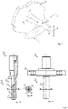
- Fig. 1 illustrates the origin of vortex shedding w at a cylindrical, conically tapered protective tube 1 exposed to a flowing medium M in a pipe 2, which is indicated by one of its walls. Downstream of the protective tube 1 in the flow direction v of the medium, a ridge-like pattern develops. Depending on the flow velocity v of the medium M, this can lead to coherent vortex shedding which in turn may cause the protective tube 1 to vibrate.
- the vibrations are mainly due to two forces acting on the protective tube 1, a shear force in the in y-direction and a lifting force in x-direction.
- the shear force causes oscillations at a frequency f s
- the lifting force causes oscillates at a frequency of 2f s .
- the frequency f s now depends on the flow velocity v of the medium M, and on various physical or chemical medium properties such as its viscosity and density, as well as on the dimensions of the protective tube 1, such as its diameter and length. The closer the frequency f s is to the natural frequency of the protective tube 1 and the higher the flow velocity v of the medium M, the greater are the resulting oscillation causing forces.
- the protective tube 1 can be damaged or even break down completely. This is known as the so-called resonance condition.
- thermowell 4 exemplarily and without limitation to such an embodiment of the protective tube 1 shows a state of the art thermometer 3 having a protective tube 1 in the form of a thermowell 4.
- the thermowell 4 comprises a tubular member 5 having a first end section 5a, and a second end section 5b with a closed end.
- the tubular member 5 further comprises a bore 6 forming a hollow space within the tubular member 5, which is defined by an inner surface s and a predeterminable height h parallel to a longitudinal axis A of the tubular member 5, which bore 6 serves for receiving a measuring insert 7 [not shown] for determining and/or monitoring the process variable, e.g. the temperature of the medium M.
- a fastening unit 8 is provided, which exemplarily is attached to the tubular member 5, here.
- This fastening unit 8 is a process connection and serves for mounting the thermowell 4 to the pipe 2 [not shown] such that the tubular member 5 at least partially extends into an inner volume of pipe 2 and such that it is at least partially in contact with the flowing medium M.
- thermowell 4 of Fig. 2 has an essentially round shape as becomes visible in Fig. 2b .
- such construction can easily lead to undesired vortex induced vibrations of the thermometer 3.
- protective tubes 1 certain structures or structural elements on the protective tube may be provided.
- One effective and easily implementable option for such protective tube 1 with reduced sensitivity to vortex induced vibrations is described in the following.
- FIG. 3a shows a sectional view of tubular member 5 of the protective tube 1 with length H.
- Fig. 3b shows a cross-sectional view of the tubular member 5 of Fig. 3a .
- the tubular member 5 comprises a surface structure 9 similar to a saguaro cactus type shape.
- the structure 9 comprises a multitude of longitudinal ribs 10, which for the embodiment shown in Fig. 3 are proceeding parallel to the length axis A of the tubular member 5.
- the ribs 10 in turn define a multitude of flow channels 11 therebetween which also proceed parallel to axis A.
- the surface structure 9 may e.g. be designed such that at least one geometrical parameter of at least one rib 10 depends on at least one process condition of the medium M in the vessel or pipe.
- Geometrical parameters of the ribs 10 are e.g. given by the numbers n of the ribs 10, and/or different forms or shapes of the ribs 10, e.g. the rib height h, a rib angle ⁇ , or a transition radius tr between a rib 10 and the tubular member 5, in particular the surface of the tubular member 5.
- the transition radius tr can e.g.
- the surface of the tubular member 5 can either remain unmodified, e.g. circular, in that transition area, or it can be curved, in particular concave.
- the surface structure 9 can be employed with a triangular r 1 , rectangular r 2 , square-type r 3 , trapezoidal r 4 , hemispherical or curved rs or polygonal rs cross-sectional area r. Any of the cross-sectional area r shapes shown can also be employed with rounded corners. Also, any geometrical parameter n, h, ⁇ , r may also vary along the length H of the tubular member 5 or between different embodiments of the tubular member 5.
- FIG. 4 A second embodiment of the protective tube 1 according to the present invention is shown in Fig. 4 .
- the tubular member 5 shown in the sectional view given in Fig. 4a comprises a surface structure 9 on its outer surface which is better visible in the enlarged section Z shown in Fig. 4b .
- the surface structure 9 comprises a multitude of ribs 10 defining a multitude of flow channels 11 therebetween.
- the ribs 10 are twisting around the tubular member 5 along its length H with a certain rib pitch p.
- the ribs 10 circle the tubular member 5 a maximum of twice. Such additional twisting highly enhances the effectiveness in minimizing vortex shedding.
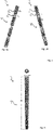
- Fig. 5 illustrated a third embodiment of the present invention in which the tubular member 5 comprises alternating sections sc 1 comprising the surface structure 9 and sections sc 2 not comprising the surface structure 9. While in case of fig. 5a the outer diameter D 1 in sections sc 1 comprising the surface structure is larger than the diameter D 2 of sections sc 2 without the surface structure, the diameters D 1 and D 2 of the different sections sc 1 and sc 2 are essentially equal in case of Fig. 5b .
- a fourth embodiment is shown in Fig. 6 .
- the outer contour of the tubular member 5, i.e its diameter D tapers between its upper 5a and lower end 5b.
- the outer diameter D of the tubular member continuously decreases from the upper 5a towards the lower 5b end section.
- Other embodiments can also employ a stepwise decrease in diameter D.
Landscapes
- Physics & Mathematics (AREA)
- General Physics & Mathematics (AREA)
- Measuring Temperature Or Quantity Of Heat (AREA)
Abstract
Description
- The invention refers to a protective tube for insertion into a pipe or vessel containing a medium and a measuring apparatus for determining and/or monitoring a process variable of a medium, comprising a protective according to the present invention.
- Protective tubes in the field of measuring inserts for determining and/or monitoring a process variable of a medium are e.g. known in the form of thermowells for thermometers which serve for determining and/or monitoring the temperature of a medium. The measuring insert of a thermometer usually at least comprises one temperature sensor for determining and/or monitoring the temperature of the medium. The temperature sensor in turn comprises at least one temperature-sensitive component, e.g. in the form of a resistive element, especially a platinum element, or in the form of a thermocouple. However, protective tubes are also known in connection with gas sampling probes, where a gas sample is, especially dynamically, taken out from a pipe or vessel. The present invention thus generally relates to fluid processing and related measurements employing insertion type probe bodies and is not restricted to thermowells or gas sampling probes.
- Such protective tubes are frequently exposed to the flow of the respective medium which causes different mechanical forces acting on the protective tube, e. g. shear forces or forces induced by coherent vortex shedding and which can result in vortex induced vibrations (VIV). Vortex shedding in fluid dynamics is known as "Kármán vortex street" and refers to a repeating pattern of swirling vortices in alternating directions caused by the unsteady separation of flow of a medium around a body, causing said body to vibrate. The closer the frequency of the vibrations is to the natural frequency of the body around which the medium flows, the more the body vibrates. The frequency of the vibrations is e. g. determined by several process parameters, such as the physical properties of the medium, the flow velocity and the shape of the body.
- Due to the high risk of damage of protective tubes subject to VIV, these vibrations e.g. need to be duly considered during production. E.g. in the case of thermometers, standard methods, such as ASME PTC 19.3 TW-2000, are available, which define several design rules that help to reduce negative effects of coherent vortex shedding. The basic principle underlying the design rules is to increase the natural frequency of vibrations of the thermometer to separate the natural frequency from the vortex shedding frequency. In such way, the dangerous condition of resonant vortex induced vibrations becomes minimized. For this purpose, commonly the geometry of the thermometer is varied, e. g. by reducing its length and/or by increasing its diameter.
- Alternatively, when functional constraints don't allow certain changes in the dimensions of the thermometer, mechanical supports or absorbers are frequently used to reduce the thermometer's sensitivity to vortex shedding. These mechanical supports or absorbers are usually fitted into a gap between the opening of the vessel or pipe and the outside surface of the thermometer. The supports or absorbers then increase the natural frequency of the thermometer by reducing the free length of the thermometer. However, it proves difficult to fit the supports or absorbers in such a way that a high level of coupling and therefore the desired effect can be achieved.
- Yet, another approach to reduce VIV of protective tubes is to provide certain structures or structural elements on the protective tube.
US 2004/0051004 A1 e.g. describes a smoothly curved protuberances which are added to an elongate body to reduce vortex shedding. The elongate bodies can then be adapted for example for use as chimneys of a factory, towers of a wind turbine, a support member of an offshore platform or an underwater cable. -
US 8,500,367 B2 in turn describes a way to protect a marine riser against vibrations caused by vortex shedding. The riser is routed through discoidal elements at regular intervals which have U-shaped indentations along their circumference. -
US 6,401,646 B1 teaches about a shell that can be secured to an underwater cable, for example. Said shell has fins at opposite locations to reduce vortex shedding. - In the field of thermometers, it has e. g. become known from
EP03184980A1 US9528918B2 - Another successful approach to reduce vortex shedding of a protective tube is to provide helical fins on the outer surface of the protective tube as e.g. described in
US3076533A ,US4991976 ,US7424396B2 ,US653931B1 ,US7836780B2 ,US2013/0142216A1 ,GB2442488A WO2020/035402A1 for different configurations. - Based on these approaches the objective technical problem underlying the present invention to provide an alternative for a protective tube with reduced sensitivity to vortex induced vibrations.
- This problem is solved by means of the protective tube according to
claim 1 and by the measuring apparatus according to claim 13. Preferred embodiments are subject to the dependent claims. - The protective tube for insertion into a pipe or vessel containing a medium according to the present invention comprises a tubular member having a bore extending between an upper and lower end of the tubular member. At least one section of an outer surface of the tubular member comprises a surface structure having a multitude of longitudinal ribs, which define a multitude of flow channels along the tubular member.
- The protective tube is usually mounted on the pipe or vessel via an opening which may have a process connection for connecting the protective tube to the vessel or pipe. The protective tube at least partially extends into an inner volume of the vessel or pipe and is at least partially in contact with the flowing medium. The protective tube may be arranged such that its longitudinal axis proceeds perpendicular to the flow direction of the medium. However, also angles between the longitudinal axis and the flow direction different from 90° can be employed.
- The present invention provides a protective tube for which at least one section of the tubular member is provided with a corrugated surface. The ribs of the surface structure preferably evolve at least partially parallel to a longitudinal axis of the tubular member. The flow channels each evolve between a pair of neighboring ribs. The surface structure drastically decreases VIV.
- In one embodiment the surface structure is designed such that at least one geometrical parameter of at least one rib depends on at least one process condition of the medium in the vessel or pipe. Choosing geometrical parameters of the surface structure in dependence of the medium enables to provide a protective tube optimized for the specific applied process. The geometrical parameter is at least one parameter defining the form and/or shape of surface structure. All these medium and pipe/vessel related parameters do have an impact on VIV. The geometrical parameters characterizing the surface structure are functions of the process conditions.
- In this regard, it is of advantage, if the process condition is at least one of a flow profile, a flow velocity, a pressure, a temperature, a density or a viscosity of the medium, a diameter, volume or roughness of the pipe or vessel, or a length or diameter of the tubular member.
- It is further of advantage, if the geometrical parameter is given by the number of ribs, by at least one parameter defining the form and/or shape of the ribs, especially a rib height, a rib angle given by the angle between a tangent to the outer contour of the tubular member and a tangent to the surface of the ribs, a cross sectional area of the ribs, or a transition radius between a rib and the tubular member, or by a quantity derived by at least one of the parameters. For instance, by means of the rib height and an outer diameter of the tubular member, a main ratio of the ribs can be derived given by the quotient of the rib height and outer diameter.
- Preferred ranges for the main ratio are 0.001<k<2, while the number of ribs is preferably two or more and the rib angle preferably is in the range between 0°-90°.
- It is also advantageously, if the at least one geometrical parameter varies along the length of the tubular member. This offers another degree of adaptability of the surface structure to a specific application.
- The protective tube can be used in a wide range of applications and can e.g. be part of a gas sampling probe with an inlet and outlet end or a Pitot tube. However, in one embodiment, the protective tube is a thermowell, and the tubular member is closed in one end section. That way, a protective tube in the form of a thermowell is provided. In such case, the protective tube may serve for receiving a measuring insert for determining and/or monitoring a process variable of a medium, especially the temperature of the medium. The measuring insert in turn preferably has a rod like form and may be inserted into the bore of the tubular member.
- Several options are available for the surface structure according to the present invention which all fall under the scope of protection of the present invention. Several preferred embodiments are depicted in the following:
One embodiment of the protective tube comprises, that the cross-sectional area of the ribs has a triangle, rectangular, square, trapezoidal, hemispherical, polygonal, or curved shape. - In another embodiment the tubular member is constructed such that it has alternating sections comprising and sections not comprising the surface structure.
- In this regard it is advantageously if an outer diameter of the sections comprising the surface structure is larger than or equal to an outer diameter of the sections not comprising the surface structure. The sections without the surface structure may e.g. be constructed in the form of a cylindrical section.
- In one embodiment, an outer contour of the tubular member tapers between its upper and lower end.
- Another embodiment comprises, that the ribs are designed such that they twist around the tubular member along its length.
- Regarding the twisting of the ribs it is of advantage, if a pitch of the twisting ribs is such that the ribs circle the tubular member a maximum of twice.
- The objective technical problem underlying the present invention is further achieved by means of a measuring apparatus for determining and/or monitoring a process variable of a medium, comprising a protective tube according to at least one of the embodiments described.
- One embodiment of the measuring apparatus comprises, that the protective tube serves for receiving a measuring insert for determining and/or monitoring a process variable of a medium, especially the temperature of a medium.
- It shall be noted that the embodiments relating to the protective tube are mutatis mutandis applicable to the measuring apparatus and vice versa.
- The present invention will now be explained in more detail by means of Figures
Fig. 1-Fig.7 . -
Fig. 1 : illustrates the origin of vortex shedding for an insertion body exposed to a flowing medium; -
Fig. 2 : shows a thermometer having a state of the art thermowell; -
Fig. 3 : shows a thermowell according to the present invention, whereas (a) shows a sectional view, (b) shows a first embodiment of the cross-sectional area of the tubular member comprising a surface structure, and (c) several possible embodiments for constructing the surface structure; -
Fig. 4 : shows a second embodiment of a protective tube in the form of a thermowell in which the ribs of the surface structure twist around the tubular member; -
Fig. 5 : shows a third embodiment of a protective tube in the form of a thermowell with alternating sections with and without the surface structure; and -
Fig. 6 : shows a fourth embodiment of a protective tube in the form of a thermowell, the outer contour of the tubular member tapering between its upper and lower end. - In the figures, the same elements are always provided with the same reference symbols.
-
Fig. 1 illustrates the origin of vortex shedding w at a cylindrical, conically taperedprotective tube 1 exposed to a flowing medium M in apipe 2, which is indicated by one of its walls. Downstream of theprotective tube 1 in the flow direction v of the medium, a ridge-like pattern develops. Depending on the flow velocity v of the medium M, this can lead to coherent vortex shedding which in turn may cause theprotective tube 1 to vibrate. - The vibrations are mainly due to two forces acting on the
protective tube 1, a shear force in the in y-direction and a lifting force in x-direction. The shear force causes oscillations at a frequency fs, while the lifting force causes oscillates at a frequency of 2fs. The frequency fs now depends on the flow velocity v of the medium M, and on various physical or chemical medium properties such as its viscosity and density, as well as on the dimensions of theprotective tube 1, such as its diameter and length. The closer the frequency fs is to the natural frequency of theprotective tube 1 and the higher the flow velocity v of the medium M, the greater are the resulting oscillation causing forces. - As a result of the vibration causing forces, the
protective tube 1 can be damaged or even break down completely. This is known as the so-called resonance condition. -
Fig. 2 exemplarily and without limitation to such an embodiment of theprotective tube 1 shows a state of theart thermometer 3 having aprotective tube 1 in the form of a thermowell 4. As can be seen inFig. 2a , the thermowell 4 comprises atubular member 5 having afirst end section 5a, and asecond end section 5b with a closed end. Thetubular member 5 further comprises abore 6 forming a hollow space within thetubular member 5, which is defined by an inner surface s and a predeterminable height h parallel to a longitudinal axis A of thetubular member 5, which bore 6 serves for receiving a measuring insert 7 [not shown] for determining and/or monitoring the process variable, e.g. the temperature of the medium M. - Further, as illustrated in
Fig. 2c , afastening unit 8 is provided, which exemplarily is attached to thetubular member 5, here. Thisfastening unit 8 is a process connection and serves for mounting the thermowell 4 to the pipe 2 [not shown] such that thetubular member 5 at least partially extends into an inner volume ofpipe 2 and such that it is at least partially in contact with the flowing medium M. - The outer surface S the thermowell 4 of
Fig. 2 has an essentially round shape as becomes visible inFig. 2b . However, such construction can easily lead to undesired vortex induced vibrations of thethermometer 3. - To overcome the problems associated with coherent vortex shedding,
protective tubes 1 certain structures or structural elements on the protective tube may be provided. One effective and easily implementable option for suchprotective tube 1 with reduced sensitivity to vortex induced vibrations is described in the following. - A first embodiment of the present invention is subject to
Fig. 3. Fig. 3a shows a sectional view oftubular member 5 of theprotective tube 1 with length H.Fig. 3b shows a cross-sectional view of thetubular member 5 ofFig. 3a . Thetubular member 5 comprises asurface structure 9 similar to a saguaro cactus type shape. Thestructure 9 comprises a multitude oflongitudinal ribs 10, which for the embodiment shown inFig. 3 are proceeding parallel to the length axis A of thetubular member 5. Theribs 10 in turn define a multitude offlow channels 11 therebetween which also proceed parallel to axis A. - Many different options exist for the concrete design of the
surface structure 9. Thesurface structure 9 may e.g. be designed such that at least one geometrical parameter of at least onerib 10 depends on at least one process condition of the medium M in the vessel or pipe. Geometrical parameters of theribs 10 are e.g. given by the numbers n of theribs 10, and/or different forms or shapes of theribs 10, e.g. the rib height h, a rib angle α, or a transition radius tr between arib 10 and thetubular member 5, in particular the surface of thetubular member 5. The transition radius tr can e.g. be such, that the surfaces of theribs 10 tangentially merge with the surface of thetubular member 10 in a transition area between twoadjacent ribs 10 thus providing for a continuous transition. The surface of thetubular member 5 on the other hand can either remain unmodified, e.g. circular, in that transition area, or it can be curved, in particular concave. - One or more geometrical parameter might differ between different embodiments. As exemplarily illustrated in
Fig. 3c , thesurface structure 9 can be employed with a triangular r1, rectangular r2, square-type r3, trapezoidal r4, hemispherical or curved rs or polygonal rs cross-sectional area r. Any of the cross-sectional area r shapes shown can also be employed with rounded corners. Also, any geometrical parameter n, h, α, r may also vary along the length H of thetubular member 5 or between different embodiments of thetubular member 5. - A second embodiment of the
protective tube 1 according to the present invention is shown inFig. 4 . Thetubular member 5 shown in the sectional view given inFig. 4a comprises asurface structure 9 on its outer surface which is better visible in the enlarged section Z shown inFig. 4b . Thesurface structure 9 comprises a multitude ofribs 10 defining a multitude offlow channels 11 therebetween. In contrast to the embodiment shown inFig. 3 theribs 10 are twisting around thetubular member 5 along its length H with a certain rib pitch p. Preferably, theribs 10 circle thetubular member 5 a maximum of twice. Such additional twisting highly enhances the effectiveness in minimizing vortex shedding. -
Fig. 5 illustrated a third embodiment of the present invention in which thetubular member 5 comprises alternating sections sc1 comprising thesurface structure 9 and sections sc2 not comprising thesurface structure 9. While in case offig. 5a the outer diameter D1 in sections sc1 comprising the surface structure is larger than the diameter D2 of sections sc2 without the surface structure, the diameters D1 and D2 of the different sections sc1 and sc2 are essentially equal in case ofFig. 5b . - Finally, a fourth embodiment is shown in
Fig. 6 . In contrast to the previously shown embodiments, the outer contour of thetubular member 5, i.e its diameter D, tapers between its upper 5a andlower end 5b. The outer diameter D of the tubular member continuously decreases from the upper 5a towards the lower 5b end section. Other embodiments can also employ a stepwise decrease in diameter D. - It shall be noted that the various embodiments shown can be arbitrarily combined with each other and that besides the preferred embodiments shown numerous alternate embodiments of the protective tubes are conceivable which also fall under the scope of protection.
-
- 1
- protective tube
- 2
- pipe, vessel
- 3
- thermometer
- 4
- thermowell
- 5
- tubular member
- 5a
- first end section
- 5b
- second end section
- 6
- bore
- 7
- measuring insert
- 8
- fastening unit
- 9
- surface structure
- 10
- ribs
- 11
- flow channel
- M
- medium
- v
- velocity of the medium
- vrel
- relative flow velocity
- v (x,y)
- flow profile
- W
- vortex shedding
- A
- longitudinal axis of the tubular member
- s
- inner cross-sectional surface
- S
- outer cross-sectional surface
- d
- pipe diameter
- H
- length of tubular member
- D, D1, D2
- diameter of tubular member
- h
- rib height
- r
- rib cross-sectional area
- α
- rib angle
- p
- rib pitch
- sc,sc1,sc2
- section of tubular member
Claims (14)
- Protective tube (1) for insertion into a pipe or vessel (2) containing a medium (M), the protective tube (1) comprising
a tubular member (5) having
a bore (6) extending between an upper (5a) and lower end (5b) of the tubular member (5),
characterized in that
at least one section (sc) of an outer surface (S) of the tubular member (5) comprises a surface structure (9) having a multitude of longitudinal ribs (10), which define a multitude of flow channels (11) along the tubular member (5). - Protective tube (1) according to claim 1,
wherein the surface structure (9) is designed such that at least one geometrical parameter of at least one rib (10) depends on at least one process condition of the medium (M) in the vessel or pipe (2). - Protective tube (1) according to claim 2,
wherein the process condition is at least one of a flow profile, a flow velocity (v), a pressure, a temperature (T), a density or a viscosity of the medium (M), a diameter (d), volume or roughness of the pipe or vessel (2), or a length (H) or diameter (D) of the tubular member (5). - Protective tube (1) according to claim 2 or 3,
wherein the geometrical parameter is given by the number (n) of ribs (10), by at least one parameter defining the form and/or shape of the ribs (10), especially a rib height (h), a rib angle (α) given by the angle between a tangent (t1) to the outer contour of the tubular member (5) and a tangent (t2) to the surface of the ribs (10), a cross sectional area (r) of the ribs (10), or a transition radius (tr) between a rib (10) and the tubular member (5), or by a quantity derived by at least one of the parameters. - Protective (1) tube according to claim 4,
wherein the at least one geometrical parameter varies along the length (H) of the tubular member (5). - Protective tube (1) according to any of the preceding claims,
wherein the protective tube (1) is a thermowell, and the tubular member (5) is closed in one end section (5b). - Protective tube (1) according to any of the preceding claims,
wherein the cross sectional area (r) of the ribs (10) has a triangle, rectangular, square, trapezoidal, hemispherical, polygonal, or curved shape. - Protective tube (1) according to any of the preceding claims,
wherein the tubular member (5) is constructed such that it has alternating sections (sc1,sc2) comprising and not comprising the surface structure (9. - Protective tube (1) according to claim 8,
wherein an outer diameter (Di) of the sections (csi) comprising the surface structure (9) is larger than or equal to an outer diameter (D2) of the sections (cs2) not comprising the surface structure (9). - Protective tube (1) according to any of the preceding claims,
wherein an outer contour of the tubular member (5) tapers between its upper (5a) and lower end (5b). - Protective tube (1) according to any of the preceding claims,
wherein the ribs (10) are designed such that they twist around the tubular member (5) along its length (H). - Protective tube (1) according to claim 11,
wherein a pitch (p) of the twisting ribs (10) is such that the ribs (10) circle the tubular member (5) a maximum of twice. - Measuring apparatus for determining and/or monitoring a process variable of a medium, comprising a protective tube (1) as claimed in at least one of the preceding claims.
- Measuring apparatus according to claim 13,
wherein the protective tube (1) serves for receiving a measuring insert for determining and/or monitoring a process variable of a medium (M), especially the temperature (T) of a medium (M).
Priority Applications (1)
| Application Number | Priority Date | Filing Date | Title |
|---|---|---|---|
| EP21161299.9A EP4056974B1 (en) | 2021-03-08 | 2021-03-08 | Measuring apparatus with thermowell with reduced sensitivity to vortex induced vibrations |
Applications Claiming Priority (1)
| Application Number | Priority Date | Filing Date | Title |
|---|---|---|---|
| EP21161299.9A EP4056974B1 (en) | 2021-03-08 | 2021-03-08 | Measuring apparatus with thermowell with reduced sensitivity to vortex induced vibrations |
Publications (2)
| Publication Number | Publication Date |
|---|---|
| EP4056974A1 true EP4056974A1 (en) | 2022-09-14 |
| EP4056974B1 EP4056974B1 (en) | 2024-05-22 |
Family
ID=74859812
Family Applications (1)
| Application Number | Title | Priority Date | Filing Date |
|---|---|---|---|
| EP21161299.9A Active EP4056974B1 (en) | 2021-03-08 | 2021-03-08 | Measuring apparatus with thermowell with reduced sensitivity to vortex induced vibrations |
Country Status (1)
| Country | Link |
|---|---|
| EP (1) | EP4056974B1 (en) |
Citations (14)
| Publication number | Priority date | Publication date | Assignee | Title |
|---|---|---|---|---|
| US653931A (en) | 1900-04-07 | 1900-07-17 | George Lowres | Eyeglasses or spectacles. |
| US3076533A (en) | 1957-11-29 | 1963-02-05 | Nat Res Dev | Stabilisation of wind-excited structures |
| US4991976A (en) | 1989-05-31 | 1991-02-12 | Weed Instruments Company, Inc. | Temperature sensor probe apparatus and method for improving time response |
| US6401646B1 (en) | 2000-09-14 | 2002-06-11 | Aims International, Inc. | Snap-on rotating reduction fairing |
| US20040051004A1 (en) | 2000-06-01 | 2004-03-18 | Bearman Peter William | Vortex shedding and drag force reduction |
| US20080031306A1 (en) * | 2006-08-03 | 2008-02-07 | Idemitsu Kosan Co., Ltd. | Protective tube structure for thermometer |
| US7424396B2 (en) | 2005-09-26 | 2008-09-09 | Intel Corporation | Method and apparatus to monitor stress conditions in a system |
| US7836780B2 (en) | 2008-02-26 | 2010-11-23 | Rosemount Inc. | Sensor tube with reduced coherent vortex shedding |
| JP2012175724A (en) * | 2011-02-17 | 2012-09-10 | Meishin Electric Co Ltd | Electric wire protection tube |
| US20130142216A1 (en) | 2011-12-01 | 2013-06-06 | Rosemount Inc. | Twisted sensor tube |
| US8500367B2 (en) | 2007-01-17 | 2013-08-06 | Trelleborg Crp Limited | Suppression of vortex induced vibration |
| US9528918B2 (en) | 2002-04-15 | 2016-12-27 | Ventana Medical Systems, Inc. | Automated high volume slide processing system |
| US20190242792A1 (en) * | 2005-12-10 | 2019-08-08 | Endet Ltd. | Gas probes |
| WO2020035402A1 (en) | 2018-08-14 | 2020-02-20 | Wika Alexander Wiegand Se & Co. Kg | Protective tube having vibration reduction |
-
2021
- 2021-03-08 EP EP21161299.9A patent/EP4056974B1/en active Active
Patent Citations (15)
| Publication number | Priority date | Publication date | Assignee | Title |
|---|---|---|---|---|
| US653931A (en) | 1900-04-07 | 1900-07-17 | George Lowres | Eyeglasses or spectacles. |
| US3076533A (en) | 1957-11-29 | 1963-02-05 | Nat Res Dev | Stabilisation of wind-excited structures |
| US4991976A (en) | 1989-05-31 | 1991-02-12 | Weed Instruments Company, Inc. | Temperature sensor probe apparatus and method for improving time response |
| US20040051004A1 (en) | 2000-06-01 | 2004-03-18 | Bearman Peter William | Vortex shedding and drag force reduction |
| US6401646B1 (en) | 2000-09-14 | 2002-06-11 | Aims International, Inc. | Snap-on rotating reduction fairing |
| US9528918B2 (en) | 2002-04-15 | 2016-12-27 | Ventana Medical Systems, Inc. | Automated high volume slide processing system |
| US7424396B2 (en) | 2005-09-26 | 2008-09-09 | Intel Corporation | Method and apparatus to monitor stress conditions in a system |
| US20190242792A1 (en) * | 2005-12-10 | 2019-08-08 | Endet Ltd. | Gas probes |
| GB2442488A (en) | 2006-08-03 | 2008-04-09 | Idemitsu Kosan Co | Protective tube structure for thermometer |
| US20080031306A1 (en) * | 2006-08-03 | 2008-02-07 | Idemitsu Kosan Co., Ltd. | Protective tube structure for thermometer |
| US8500367B2 (en) | 2007-01-17 | 2013-08-06 | Trelleborg Crp Limited | Suppression of vortex induced vibration |
| US7836780B2 (en) | 2008-02-26 | 2010-11-23 | Rosemount Inc. | Sensor tube with reduced coherent vortex shedding |
| JP2012175724A (en) * | 2011-02-17 | 2012-09-10 | Meishin Electric Co Ltd | Electric wire protection tube |
| US20130142216A1 (en) | 2011-12-01 | 2013-06-06 | Rosemount Inc. | Twisted sensor tube |
| WO2020035402A1 (en) | 2018-08-14 | 2020-02-20 | Wika Alexander Wiegand Se & Co. Kg | Protective tube having vibration reduction |
Also Published As
| Publication number | Publication date |
|---|---|
| EP4056974B1 (en) | 2024-05-22 |
Similar Documents
| Publication | Publication Date | Title |
|---|---|---|
| EP2786106B1 (en) | Twisted sensor tube | |
| US7836780B2 (en) | Sensor tube with reduced coherent vortex shedding | |
| US20230266173A1 (en) | Protective tube with reduced sensitivity to vortex induced vibrations | |
| USRE36285E (en) | Thermocouple probe | |
| US11976766B2 (en) | Protective tube for insertion into a pipe or vessel with reduced sensitivity to vortex induced vibrations | |
| EP3184980B1 (en) | Temperature sensor for measuring the temperature of a medium in a vessel or a pipe | |
| EP3184979A1 (en) | Temperature sensor for recording the temperature of a flowing medium in a vessel or a pipe | |
| EP4056974B1 (en) | Measuring apparatus with thermowell with reduced sensitivity to vortex induced vibrations | |
| US10545037B2 (en) | Flow line insert with indentations | |
| US20220220987A1 (en) | Protective tube for insertion into a pipe or vessel with reduced sensitivity to vortex induced vibrations | |
| CN111492208B (en) | Coriolis Flow Sensor Assembly | |
| EP3553482A1 (en) | Thermowell with reduced sensitivity to vortex induced vibrations | |
| RU2838352C9 (en) | Protective sleeve for temperature sensor | |
| RU2838352C1 (en) | Protective sleeve for temperature sensor | |
| CN109556744A (en) | A kind of antivibration spiral shape protection sleeve pipe | |
| RU2575136C1 (en) | Twisted sensor tube | |
| US20220268610A1 (en) | Immersion probes and related methods |
Legal Events
| Date | Code | Title | Description |
|---|---|---|---|
| PUAI | Public reference made under article 153(3) epc to a published international application that has entered the european phase |
Free format text: ORIGINAL CODE: 0009012 |
|
| STAA | Information on the status of an ep patent application or granted ep patent |
Free format text: STATUS: THE APPLICATION HAS BEEN PUBLISHED |
|
| AK | Designated contracting states |
Kind code of ref document: A1 Designated state(s): AL AT BE BG CH CY CZ DE DK EE ES FI FR GB GR HR HU IE IS IT LI LT LU LV MC MK MT NL NO PL PT RO RS SE SI SK SM TR |
|
| STAA | Information on the status of an ep patent application or granted ep patent |
Free format text: STATUS: REQUEST FOR EXAMINATION WAS MADE |
|
| 17P | Request for examination filed |
Effective date: 20230306 |
|
| RBV | Designated contracting states (corrected) |
Designated state(s): AL AT BE BG CH CY CZ DE DK EE ES FI FR GB GR HR HU IE IS IT LI LT LU LV MC MK MT NL NO PL PT RO RS SE SI SK SM TR |
|
| GRAP | Despatch of communication of intention to grant a patent |
Free format text: ORIGINAL CODE: EPIDOSNIGR1 |
|
| STAA | Information on the status of an ep patent application or granted ep patent |
Free format text: STATUS: GRANT OF PATENT IS INTENDED |
|
| INTG | Intention to grant announced |
Effective date: 20240118 |
|
| GRAS | Grant fee paid |
Free format text: ORIGINAL CODE: EPIDOSNIGR3 |
|
| GRAA | (expected) grant |
Free format text: ORIGINAL CODE: 0009210 |
|
| STAA | Information on the status of an ep patent application or granted ep patent |
Free format text: STATUS: THE PATENT HAS BEEN GRANTED |
|
| AK | Designated contracting states |
Kind code of ref document: B1 Designated state(s): AL AT BE BG CH CY CZ DE DK EE ES FI FR GB GR HR HU IE IS IT LI LT LU LV MC MK MT NL NO PL PT RO RS SE SI SK SM TR |
|
| REG | Reference to a national code |
Ref country code: GB Ref legal event code: FG4D |
|
| REG | Reference to a national code |
Ref country code: CH Ref legal event code: EP |
|
| REG | Reference to a national code |
Ref country code: DE Ref legal event code: R096 Ref document number: 602021013450 Country of ref document: DE |
|
| REG | Reference to a national code |
Ref country code: IE Ref legal event code: FG4D |
|
| REG | Reference to a national code |
Ref country code: LT Ref legal event code: MG9D |
|
| REG | Reference to a national code |
Ref country code: NL Ref legal event code: MP Effective date: 20240522 |
|
| P01 | Opt-out of the competence of the unified patent court (upc) registered |
Free format text: CASE NUMBER: APP_48853/2024 Effective date: 20240827 |
|
| PG25 | Lapsed in a contracting state [announced via postgrant information from national office to epo] |
Ref country code: IS Free format text: LAPSE BECAUSE OF FAILURE TO SUBMIT A TRANSLATION OF THE DESCRIPTION OR TO PAY THE FEE WITHIN THE PRESCRIBED TIME-LIMIT Effective date: 20240922 |
|
| PG25 | Lapsed in a contracting state [announced via postgrant information from national office to epo] |
Ref country code: BG Free format text: LAPSE BECAUSE OF FAILURE TO SUBMIT A TRANSLATION OF THE DESCRIPTION OR TO PAY THE FEE WITHIN THE PRESCRIBED TIME-LIMIT Effective date: 20240522 |
|
| PG25 | Lapsed in a contracting state [announced via postgrant information from national office to epo] |
Ref country code: FI Free format text: LAPSE BECAUSE OF FAILURE TO SUBMIT A TRANSLATION OF THE DESCRIPTION OR TO PAY THE FEE WITHIN THE PRESCRIBED TIME-LIMIT Effective date: 20240522 Ref country code: HR Free format text: LAPSE BECAUSE OF FAILURE TO SUBMIT A TRANSLATION OF THE DESCRIPTION OR TO PAY THE FEE WITHIN THE PRESCRIBED TIME-LIMIT Effective date: 20240522 |
|
| PG25 | Lapsed in a contracting state [announced via postgrant information from national office to epo] |
Ref country code: GR Free format text: LAPSE BECAUSE OF FAILURE TO SUBMIT A TRANSLATION OF THE DESCRIPTION OR TO PAY THE FEE WITHIN THE PRESCRIBED TIME-LIMIT Effective date: 20240823 |
|
| PG25 | Lapsed in a contracting state [announced via postgrant information from national office to epo] |
Ref country code: PT Free format text: LAPSE BECAUSE OF FAILURE TO SUBMIT A TRANSLATION OF THE DESCRIPTION OR TO PAY THE FEE WITHIN THE PRESCRIBED TIME-LIMIT Effective date: 20240923 |
|
| REG | Reference to a national code |
Ref country code: AT Ref legal event code: MK05 Ref document number: 1689137 Country of ref document: AT Kind code of ref document: T Effective date: 20240522 |
|
| PG25 | Lapsed in a contracting state [announced via postgrant information from national office to epo] |
Ref country code: NL Free format text: LAPSE BECAUSE OF FAILURE TO SUBMIT A TRANSLATION OF THE DESCRIPTION OR TO PAY THE FEE WITHIN THE PRESCRIBED TIME-LIMIT Effective date: 20240522 |
|
| PG25 | Lapsed in a contracting state [announced via postgrant information from national office to epo] |
Ref country code: ES Free format text: LAPSE BECAUSE OF FAILURE TO SUBMIT A TRANSLATION OF THE DESCRIPTION OR TO PAY THE FEE WITHIN THE PRESCRIBED TIME-LIMIT Effective date: 20240522 |
|
| PG25 | Lapsed in a contracting state [announced via postgrant information from national office to epo] |
Ref country code: AT Free format text: LAPSE BECAUSE OF FAILURE TO SUBMIT A TRANSLATION OF THE DESCRIPTION OR TO PAY THE FEE WITHIN THE PRESCRIBED TIME-LIMIT Effective date: 20240522 |
|
| PG25 | Lapsed in a contracting state [announced via postgrant information from national office to epo] |
Ref country code: PL Free format text: LAPSE BECAUSE OF FAILURE TO SUBMIT A TRANSLATION OF THE DESCRIPTION OR TO PAY THE FEE WITHIN THE PRESCRIBED TIME-LIMIT Effective date: 20240522 |
|
| PG25 | Lapsed in a contracting state [announced via postgrant information from national office to epo] |
Ref country code: LV Free format text: LAPSE BECAUSE OF FAILURE TO SUBMIT A TRANSLATION OF THE DESCRIPTION OR TO PAY THE FEE WITHIN THE PRESCRIBED TIME-LIMIT Effective date: 20240522 |
|
| PG25 | Lapsed in a contracting state [announced via postgrant information from national office to epo] |
Ref country code: PT Free format text: LAPSE BECAUSE OF FAILURE TO SUBMIT A TRANSLATION OF THE DESCRIPTION OR TO PAY THE FEE WITHIN THE PRESCRIBED TIME-LIMIT Effective date: 20240923 Ref country code: PL Free format text: LAPSE BECAUSE OF FAILURE TO SUBMIT A TRANSLATION OF THE DESCRIPTION OR TO PAY THE FEE WITHIN THE PRESCRIBED TIME-LIMIT Effective date: 20240522 Ref country code: NO Free format text: LAPSE BECAUSE OF FAILURE TO SUBMIT A TRANSLATION OF THE DESCRIPTION OR TO PAY THE FEE WITHIN THE PRESCRIBED TIME-LIMIT Effective date: 20240822 Ref country code: NL Free format text: LAPSE BECAUSE OF FAILURE TO SUBMIT A TRANSLATION OF THE DESCRIPTION OR TO PAY THE FEE WITHIN THE PRESCRIBED TIME-LIMIT Effective date: 20240522 Ref country code: LV Free format text: LAPSE BECAUSE OF FAILURE TO SUBMIT A TRANSLATION OF THE DESCRIPTION OR TO PAY THE FEE WITHIN THE PRESCRIBED TIME-LIMIT Effective date: 20240522 Ref country code: IS Free format text: LAPSE BECAUSE OF FAILURE TO SUBMIT A TRANSLATION OF THE DESCRIPTION OR TO PAY THE FEE WITHIN THE PRESCRIBED TIME-LIMIT Effective date: 20240922 Ref country code: HR Free format text: LAPSE BECAUSE OF FAILURE TO SUBMIT A TRANSLATION OF THE DESCRIPTION OR TO PAY THE FEE WITHIN THE PRESCRIBED TIME-LIMIT Effective date: 20240522 Ref country code: GR Free format text: LAPSE BECAUSE OF FAILURE TO SUBMIT A TRANSLATION OF THE DESCRIPTION OR TO PAY THE FEE WITHIN THE PRESCRIBED TIME-LIMIT Effective date: 20240823 Ref country code: FI Free format text: LAPSE BECAUSE OF FAILURE TO SUBMIT A TRANSLATION OF THE DESCRIPTION OR TO PAY THE FEE WITHIN THE PRESCRIBED TIME-LIMIT Effective date: 20240522 Ref country code: ES Free format text: LAPSE BECAUSE OF FAILURE TO SUBMIT A TRANSLATION OF THE DESCRIPTION OR TO PAY THE FEE WITHIN THE PRESCRIBED TIME-LIMIT Effective date: 20240522 Ref country code: BG Free format text: LAPSE BECAUSE OF FAILURE TO SUBMIT A TRANSLATION OF THE DESCRIPTION OR TO PAY THE FEE WITHIN THE PRESCRIBED TIME-LIMIT Effective date: 20240522 Ref country code: AT Free format text: LAPSE BECAUSE OF FAILURE TO SUBMIT A TRANSLATION OF THE DESCRIPTION OR TO PAY THE FEE WITHIN THE PRESCRIBED TIME-LIMIT Effective date: 20240522 Ref country code: RS Free format text: LAPSE BECAUSE OF FAILURE TO SUBMIT A TRANSLATION OF THE DESCRIPTION OR TO PAY THE FEE WITHIN THE PRESCRIBED TIME-LIMIT Effective date: 20240822 |
|
| PG25 | Lapsed in a contracting state [announced via postgrant information from national office to epo] |
Ref country code: DK Free format text: LAPSE BECAUSE OF FAILURE TO SUBMIT A TRANSLATION OF THE DESCRIPTION OR TO PAY THE FEE WITHIN THE PRESCRIBED TIME-LIMIT Effective date: 20240522 |
|
| PG25 | Lapsed in a contracting state [announced via postgrant information from national office to epo] |
Ref country code: EE Free format text: LAPSE BECAUSE OF FAILURE TO SUBMIT A TRANSLATION OF THE DESCRIPTION OR TO PAY THE FEE WITHIN THE PRESCRIBED TIME-LIMIT Effective date: 20240522 |
|
| PG25 | Lapsed in a contracting state [announced via postgrant information from national office to epo] |
Ref country code: CZ Free format text: LAPSE BECAUSE OF FAILURE TO SUBMIT A TRANSLATION OF THE DESCRIPTION OR TO PAY THE FEE WITHIN THE PRESCRIBED TIME-LIMIT Effective date: 20240522 |
|
| PG25 | Lapsed in a contracting state [announced via postgrant information from national office to epo] |
Ref country code: SK Free format text: LAPSE BECAUSE OF FAILURE TO SUBMIT A TRANSLATION OF THE DESCRIPTION OR TO PAY THE FEE WITHIN THE PRESCRIBED TIME-LIMIT Effective date: 20240522 Ref country code: RO Free format text: LAPSE BECAUSE OF FAILURE TO SUBMIT A TRANSLATION OF THE DESCRIPTION OR TO PAY THE FEE WITHIN THE PRESCRIBED TIME-LIMIT Effective date: 20240522 |
|
| PG25 | Lapsed in a contracting state [announced via postgrant information from national office to epo] |
Ref country code: SK Free format text: LAPSE BECAUSE OF FAILURE TO SUBMIT A TRANSLATION OF THE DESCRIPTION OR TO PAY THE FEE WITHIN THE PRESCRIBED TIME-LIMIT Effective date: 20240522 Ref country code: RO Free format text: LAPSE BECAUSE OF FAILURE TO SUBMIT A TRANSLATION OF THE DESCRIPTION OR TO PAY THE FEE WITHIN THE PRESCRIBED TIME-LIMIT Effective date: 20240522 Ref country code: EE Free format text: LAPSE BECAUSE OF FAILURE TO SUBMIT A TRANSLATION OF THE DESCRIPTION OR TO PAY THE FEE WITHIN THE PRESCRIBED TIME-LIMIT Effective date: 20240522 Ref country code: DK Free format text: LAPSE BECAUSE OF FAILURE TO SUBMIT A TRANSLATION OF THE DESCRIPTION OR TO PAY THE FEE WITHIN THE PRESCRIBED TIME-LIMIT Effective date: 20240522 Ref country code: CZ Free format text: LAPSE BECAUSE OF FAILURE TO SUBMIT A TRANSLATION OF THE DESCRIPTION OR TO PAY THE FEE WITHIN THE PRESCRIBED TIME-LIMIT Effective date: 20240522 |
|
| REG | Reference to a national code |
Ref country code: DE Ref legal event code: R097 Ref document number: 602021013450 Country of ref document: DE |
|
| PLBE | No opposition filed within time limit |
Free format text: ORIGINAL CODE: 0009261 |
|
| STAA | Information on the status of an ep patent application or granted ep patent |
Free format text: STATUS: NO OPPOSITION FILED WITHIN TIME LIMIT |
|
| PG25 | Lapsed in a contracting state [announced via postgrant information from national office to epo] |
Ref country code: SI Free format text: LAPSE BECAUSE OF FAILURE TO SUBMIT A TRANSLATION OF THE DESCRIPTION OR TO PAY THE FEE WITHIN THE PRESCRIBED TIME-LIMIT Effective date: 20240522 |
|
| 26N | No opposition filed |
Effective date: 20250225 |
|
| PG25 | Lapsed in a contracting state [announced via postgrant information from national office to epo] |
Ref country code: SE Free format text: LAPSE BECAUSE OF FAILURE TO SUBMIT A TRANSLATION OF THE DESCRIPTION OR TO PAY THE FEE WITHIN THE PRESCRIBED TIME-LIMIT Effective date: 20240522 |
|
| PG25 | Lapsed in a contracting state [announced via postgrant information from national office to epo] |
Ref country code: MC Free format text: LAPSE BECAUSE OF FAILURE TO SUBMIT A TRANSLATION OF THE DESCRIPTION OR TO PAY THE FEE WITHIN THE PRESCRIBED TIME-LIMIT Effective date: 20240522 |
|
| REG | Reference to a national code |
Ref country code: CH Ref legal event code: H13 Free format text: ST27 STATUS EVENT CODE: U-0-0-H10-H13 (AS PROVIDED BY THE NATIONAL OFFICE) Effective date: 20251023 |
|
| PG25 | Lapsed in a contracting state [announced via postgrant information from national office to epo] |
Ref country code: LU Free format text: LAPSE BECAUSE OF NON-PAYMENT OF DUE FEES Effective date: 20250308 |
|
| GBPC | Gb: european patent ceased through non-payment of renewal fee |
Effective date: 20250308 |
|
| REG | Reference to a national code |
Ref country code: BE Ref legal event code: MM Effective date: 20250331 |
|
| PG25 | Lapsed in a contracting state [announced via postgrant information from national office to epo] |
Ref country code: GB Free format text: LAPSE BECAUSE OF NON-PAYMENT OF DUE FEES Effective date: 20250308 |
|
| PG25 | Lapsed in a contracting state [announced via postgrant information from national office to epo] |
Ref country code: FR Free format text: LAPSE BECAUSE OF NON-PAYMENT OF DUE FEES Effective date: 20250331 |
|
| PG25 | Lapsed in a contracting state [announced via postgrant information from national office to epo] |
Ref country code: BE Free format text: LAPSE BECAUSE OF NON-PAYMENT OF DUE FEES Effective date: 20250331 |
|
| PG25 | Lapsed in a contracting state [announced via postgrant information from national office to epo] |
Ref country code: CH Free format text: LAPSE BECAUSE OF NON-PAYMENT OF DUE FEES Effective date: 20250331 |
|
| PG25 | Lapsed in a contracting state [announced via postgrant information from national office to epo] |
Ref country code: IE Free format text: LAPSE BECAUSE OF NON-PAYMENT OF DUE FEES Effective date: 20250308 |
|
| PGFP | Annual fee paid to national office [announced via postgrant information from national office to epo] |
Ref country code: DE Payment date: 20260319 Year of fee payment: 6 |
|
| PGFP | Annual fee paid to national office [announced via postgrant information from national office to epo] |
Ref country code: IT Payment date: 20260324 Year of fee payment: 6 |