EP4056936A1 - Built-in refrigerator, and installation device and auxiliary installation assembly therefor - Google Patents
Built-in refrigerator, and installation device and auxiliary installation assembly therefor Download PDFInfo
- Publication number
- EP4056936A1 EP4056936A1 EP20910929.7A EP20910929A EP4056936A1 EP 4056936 A1 EP4056936 A1 EP 4056936A1 EP 20910929 A EP20910929 A EP 20910929A EP 4056936 A1 EP4056936 A1 EP 4056936A1
- Authority
- EP
- European Patent Office
- Prior art keywords
- refrigerator
- installation
- assembly
- disposed
- built
- Prior art date
- Legal status (The legal status is an assumption and is not a legal conclusion. Google has not performed a legal analysis and makes no representation as to the accuracy of the status listed.)
- Granted
Links
Images






Classifications
-
- F—MECHANICAL ENGINEERING; LIGHTING; HEATING; WEAPONS; BLASTING
- F25—REFRIGERATION OR COOLING; COMBINED HEATING AND REFRIGERATION SYSTEMS; HEAT PUMP SYSTEMS; MANUFACTURE OR STORAGE OF ICE; LIQUEFACTION SOLIDIFICATION OF GASES
- F25D—REFRIGERATORS; COLD ROOMS; ICE-BOXES; COOLING OR FREEZING APPARATUS NOT OTHERWISE PROVIDED FOR
- F25D23/00—General constructional features
- F25D23/10—Arrangements for mounting in particular locations, e.g. for built-in type, for corner type
-
- F—MECHANICAL ENGINEERING; LIGHTING; HEATING; WEAPONS; BLASTING
- F25—REFRIGERATION OR COOLING; COMBINED HEATING AND REFRIGERATION SYSTEMS; HEAT PUMP SYSTEMS; MANUFACTURE OR STORAGE OF ICE; LIQUEFACTION SOLIDIFICATION OF GASES
- F25D—REFRIGERATORS; COLD ROOMS; ICE-BOXES; COOLING OR FREEZING APPARATUS NOT OTHERWISE PROVIDED FOR
- F25D23/00—General constructional features
-
- F—MECHANICAL ENGINEERING; LIGHTING; HEATING; WEAPONS; BLASTING
- F25—REFRIGERATION OR COOLING; COMBINED HEATING AND REFRIGERATION SYSTEMS; HEAT PUMP SYSTEMS; MANUFACTURE OR STORAGE OF ICE; LIQUEFACTION SOLIDIFICATION OF GASES
- F25D—REFRIGERATORS; COLD ROOMS; ICE-BOXES; COOLING OR FREEZING APPARATUS NOT OTHERWISE PROVIDED FOR
- F25D2323/00—General constructional features not provided for in other groups of this subclass
- F25D2323/0011—Means for leveling refrigerators
Definitions
- the present invention relates to the field of refrigerators, and in particular to a built-in refrigerator, and an installation device and an auxiliary installation assembly therefor.
- Installing a built-in refrigerator demands embedding a box body into a reserved installation space in a household cabinet.
- the volume of the installation space is approximately equal to that of the box body, in the process of the installation, the user can only apply acting force on the front side of the box body to push the box body into the installation space.
- An object of the present invention is to provide a built-in refrigerator, and an installation device and an auxiliary installation assembly therefor which are capable of at least solving any one of the aspects in the above technical problem.
- a further object of the present invention is to enable the built-in refrigerator to get in and out of the installation space in a fixed direction, so that the installation difficulty of the built-in refrigerator is reduced.
- a further object of the present invention is to achieve a quick installation of the built-in refrigerator.
- a further object of the present invention is to reinforce the integrity between the built-in refrigerator and a cabinet.
- a further object of the present invention is to improve the installation aesthetics of the built-in refrigerator.
- an installation device for a built-in refrigerator is provided, and is used for installing the built-in refrigerator into an installation space in a cabinet.
- the installation device includes: a fixing frame, disposed on a bottom plate of the refrigerator in a front-back extension direction of the refrigerator; and at least one guide block, disposed on the fixing frame, wherein the bottom of the guide block is provided with a groove parallel to the front-back extension direction of the refrigerator, and the groove is configured to match a guide rail portion pre-installed on the ground where the installation space is located, to limit the refrigerator to move in the front-back direction.
- the number of the guide block is more than one, the guide blocks being disposed at intervals along the fixing frame, and grooves of the plurality of the guide blocks are at a same straight line parallel to the front-back extension direction of the refrigerator.
- the plurality of guide blocks includes: a first guide block, located at the back end of the fixing frame; the back portion of the first guide block is formed with a bell mouth expanding backward from a lateral side wall of the groove, and the bell mouth is configured to be assembled with one side of the guide rail portion that faces the outside of the installation space, to guide the refrigerator onto the guide rail portion.
- the installation device further includes a plurality of pulley assemblies disposed in the intervals between the plurality of guide blocks and configured to slide along the surface of the guide rail portion to decrease frictional resistance generated when the refrigerator moves.
- the pulley assembly include: a plurality of runners sequentially arranged in an extension direction of the groove, wherein the outer peripheral edge of the runners is formed in a shape matching the top end of the guide rail portion; and a connector having a shaft hole for matching the two ends of a central rotating shaft of each runner, so that the central rotating shaft of the plurality of runners is rotatably connected onto the connector.
- the number of the connectors is two, the connectors are respectively on two lateral sides of the plurality of runners, and the pulley assembly further include: a fixing shaft disposed between the two connectors in a penetrating manner; and a cover housing fixedly connected to the two ends of the fixing shaft and configured to limit the runners in the cover housing, wherein the bottom of the cover housing is provided with an opening to allow the runners to be in contact with the surface of the guide rail portion.
- the installation device further includes a plurality of leveling feet disposed at the bottom of the refrigerator, located in front of a front bottom pulley of the refrigerator, and configured to level the refrigerator by adjusting a height thereof.
- a built-in refrigerator including: a box body; and the installation device as described in any one of the foregoing items disposed at the bottom of the box body.
- an auxiliary installation assembly for a built-in refrigerator is further provided to install a refrigerator into an installation space in a cabinet
- the auxiliary installation assembly including: a rail assembly configured to at least be disposed on a lateral side of the ground where the installation space is located, and configured to be disposed in a front-back extension direction of the ground, to allow the refrigerator to get in and out of the installation space in the front-back direction
- the rail assembly includes: a bottom plate portion, configured to be laid on the ground; and a guide rail portion formed extending upward from the surface of the bottom plate portion and configured to allow a guide block of the installation device as described in any one of the foregoing items to move along the surface thereof.
- the rail assembly further includes: a limiting portion formed extending upward from the surface of the bottom plate portion and disposed parallel to the guide rail portion at an interval;
- the auxiliary installation assembly further includes: a positioning member configured to be disposed on the ground parallel to an extension direction of the rail assembly, and having a positioning strip parallel to the limiting portion, wherein the guide rail portion is located between the positioning strip and the limiting portion, and the positioning member is further configured to match the limiting portion to adjust a moving path of the refrigerator when the guide block deviates from the guide rail portion; and a pad located between the rail assembly and the positioning member and configured to elevate a back bottom pulley of the refrigerator when the refrigerator moves to an installation position.
- the installation device for the built-in refrigerator includes a guide block, wherein the bottom of the guide block is provided with a groove parallel to a front-back extension direction of the refrigerator, and the groove is configured to match with a guide rail portion pre-installed on the ground where the installation space is located to limit the refrigerator to move in the front-back direction, so that the refrigerator can move backward along a preset path to the installation position, the operation is simple, time-saving and labor-saving, avoiding the problem that in a moving process, due to uneven stress, the box body of the refrigerator is skewed, moves forward in a winding manner, and can hardly get in and out of the installation space, and reducing the installation difficulty of the built-in refrigerator.
- the built-in refrigerator can move to the installation position along the preset path, so that the refrigerator can be moved in one step, thereby avoiding repeatedly adjusting the position of the refrigerator in the process of installation, improving an installation efficiency of the built-in refrigerator, and achieving a quick installation of the built-in refrigerator.
- the position of the auxiliary installation assembly on the ground where the installation space is located can be adjusted to adjust the size of a gap between the refrigerator and the side wall of the cabinet as well as the refrigerator and the back wall of the cabinet, so that the refrigerator and the cabinet are kept flush, reinforcing the integrity between the built-in refrigerator and the cabinet.
- the auxiliary installation assembly includes a pad pre-installed on the ground and configured to elevate the back portion of the refrigerator when the refrigerator moves to an installation position;
- the installation device further includes a plurality of leveling feet disposed at the bottom of the refrigerator and configured to level the refrigerator by adjusting a height thereof, wherein the pad is first used to elevate the back portion of the refrigerator, and then the leveling feet are used to adjust the height of the front portion of the refrigerator, which is convenient and efficient, can quickly adjust the top and bottom of the refrigerator to the same horizontal plane after the refrigerator reaches the installation position, improving the aesthetics of the built-in refrigerator.
- FIG. 1 is an assembly view of a built-in refrigerator 10 according to an embodiment of the present invention
- FIG. 2 is a left view of a built-in refrigerator 10 according to an embodiment of the present invention
- FIG. 3 is a partial enlarged view of part A in FIG. 2
- FIG. 4 is a bottom view of the built-in refrigerator 10 shown in FIG. 2 .
- the built-in refrigerator 10 may generally include: a box body and an installation device 100 disposed at the bottom of the box body.
- the bottom of the refrigerator 10 may be pre-installed with a bottom pulley, and the number of the bottom pulley may be four, the bottom pulley including two front pulleys 600 and two back pulleys 700.
- the installation device 100 for the built-in refrigerator 10 is used for installing the refrigerator 10 into a cabinet 20, and an installation space of the refrigerator 10 is formed in the cabinet 20.
- the cuboid-shaped installation space is enclosed jointly by a back wall, a side wall and a top wall of the cabinet 20 as well as the ground where the installation space is located.
- An installation position of the refrigerator 10 refers to a specific position of the refrigerator 10 in the installation space.
- the installation space can accommodate the single refrigerator 10, and can also accommodate the modular refrigerator 10 in any quantity, and the specific arrangement plan can be determined according to a practical need.
- the installation space can accommodate two modular refrigerators 10 which can be parallelly disposed in a lateral extension direction of the installation space.
- FIG. 5 is a schematic diagram of an auxiliary installation assembly 500 for the built-in refrigerator 10 according to an embodiment of the present invention.
- the built-in refrigerator 10 may further include the auxiliary installation assembly 500.
- the auxiliary installation assembly 500 for a built-in refrigerator 10 is used for installing the refrigerator 10 into an installation space in a cabinet 20.
- the auxiliary installation assembly 500 is configured to be pre-installed on the ground where the installation space is located, is used for assisting in limiting a moving path and an installation position of the refrigerator 10, and is further used for assisting in leveling the refrigerator 10.
- the auxiliary installation assembly 500 includes: a rail assembly 510, a positioning member 520 and a pad 530.
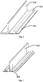
- FIG. 6 is a schematic diagram of a rail assembly 510 of the auxiliary installation assembly 500 for the built-in refrigerator 10 shown in FIG. 5 .
- the rail assembly 510 is configured to at least be disposed on a lateral side of the ground where the installation space is located, and is configured to be disposed in a front-back extension direction of the ground, to allow the refrigerator 10 to get in and out of the installation space in the front-back direction.
- the number of the built-in refrigerator 10 is two, and the number of the rail assembly 510 may be two; the rail assemblies 510 are used for being pre-installed on the lateral side of the above ground respectively, and are used for limiting the moving path and the installation position of each refrigerator 10.
- the number of the built-in refrigerator 10 is one, and the number of the rail assembly 510 may be one, or may be two.
- the rail assembly 510 can be fixed on the ground by means of screw connection or adhesion.
- the rail assembly 510 includes a bottom plate portion 511, a guide rail portion 512 and a limiting portion 513.
- the definitions of the auxiliary installation assembly 500 and terms “front”, “rear”, “back”, “side”, “top”, and the like used to indicate the orientation or positional relationship are relative to the actual usage state of the auxiliary installation assembly 500 on the ground where the installation space is located.
- the definitions of an installation device 100 and terms “front”, “rear”, “back”, “side”, “top”, and the like used to indicate the orientation or positional relationship are relative to the actual usage state of the refrigerator 10 in the installation space.
- the bottom plate portion 511 is configured to be laid on the ground. According to the rail assembly 510, the bottom plate portion 511 can be connected on the ground by screw or adhesive on the ground to achieve the integral fixing of the rail assembly 510.
- the bottom plate portion 511 may be in a rectangular plate shape extending from the front to the back in parallel to the front-back extension direction of the ground. A side of the bottom plate portion 511 close to a side wall of a cabinet 20 can be disposed by abutting against the side wall of the cabinet 20.
- a side of the bottom plate portion 511 close to a back wall of the cabinet 20 may be spaced at a preset distance from the back wall of the cabinet 20, and the size of the preset distance can be set according to a practical need, so that a gap with a determined size can be formed between a wall plate of the refrigerator 10 and the back wall of the cabinet 20.
- the guide rail portion 512 is formed extending upward from the surface of the bottom plate portion 511 and is configured to allow a guide block of the installation device 100 mentioned below to move along the surface thereof. That is, the guide rail portion 512 forms a moving track of the guide block. In this embodiment, the guide rail portion 512 forms a moving track of the guide block and a pulley assembly 220.
- the guide rail portion 512 may be in a plate shape, be perpendicular to the bottom plate portion 511, and be disposed parallel to the front-back extension direction of the ground.
- the guide rail portion 512 keeps parallel to the side wall of the cabinet 20 to enable the refrigerator 10, in the process of moving into the installation position from the front to the back, to keep parallel to the side wall of the cabinet 20 all the time, so that the size of the gap does not need to be adjusted again repeatedly between the refrigerator 10 and the side wall of the cabinet 20 after the refrigerator 10 reaching the installation position, improving an installation efficiency.
- the part of the guide rail portion 512 in contact with a groove 212 of the guide block can be set as a smooth curved surface, so that the curved surface and the groove 212 of the guide block can mutually match to reduce the reduce the frictional resistance appearing when the refrigerator 10 moves.
- a side of the guide rail portion 512 close to the back wall of the cabinet 20 may be provided with a stopper for preventing the refrigerator 10 from moving backward after reaching the installation device 100, thereby making the refrigerator 10 stop moving. After stopping moving, the refrigerator 10 reaches a specified installation position.
- the stopper may be spaced a fixed distance from the back wall of the cabinet 20, and the length of the fixed distance can be set according to a practical need, so that a gap with a determined size can be formed between a back plate of the refrigerator 10 and the back wall of the cabinet 20.
- the above auxiliary installation assembly 500 of the present embodiment not only provides a preset moving track for the refrigerator 10 to ensure that the refrigerator 10 performs a linear motion along the preset path to move to the installation position, but also can enable the refrigerator 10 to reach the installation position specified by a user, and provide a gap between the refrigerator 10 and the cabinet 20, wherein the size of the gap can be adjusted by adjusting the position of the auxiliary installation assembly 500, improving the installation flexibility of the refrigerator 10.
- the limiting portion 513 is formed extending upward from the surface of the bottom plate portion 511, and is disposed parallel to the guide rail portion 512 at an interval.
- the limiting portion 513 is higher than the guide rail portion 512, and is further configured to be parallel to the side wall of the cabinet 20, and to adjoin the side wall of the refrigerator 10 and a fixing frame 240 of the installation device 100 when the refrigerator 10 moves, so as to adjust the moving path of the refrigerator 10 when the guide block deviates from the guide rail portion 512.
- the limiting portion 513 is used for preventing the guide block from disengaging from the guide rail portion 512, and the limiting portion 513 cooperates with the guide rail portion 512 so that the guide block moves from the front to the back strictly in a direction parallel to the side wall of the cabinet 20.
- the limiting portion 513 may be in a plate shape, be perpendicular to the bottom plate portion 511, and be disposed in a front-back extension direction of the ground.
- the limiting portion 513 may be on the side of the bottom plate portion 511 close to the side wall of the cabinet 20, and the guide rail portion 512 may be on the side of the bottom plate portion 511 away from the side wall of the above cabinet 20.
- the limiting portion 513 may be spaced at a set distance from the side wall of the cabinet 20, and the length of the set distance can be set according to a practical need, so that the gap with a determined size can be formed between a side plate of the refrigerator 10 and the side wall of the cabinet 20.
- the groove 212 of the guide block can be engaged with the guide rail portion 512, and the surface of the guide block that faces the side wall of the cabinet 20 can further abut against the limiting portion 513, the guide rail portion 512 and the limiting portion 513 mutually match to strictly limit the moving path of the refrigerator 10, to enable the refrigerator 10 to reach the specified installation position along the preset path, and at the same time, after the refrigerator 10 reaches the installation position, to provide gaps with a determined size between the refrigerator 10 and the side wall of the cabinet 20 as well as the refrigerator 10 and the back wall of the cabinet 20, so that the position of the refrigerator 10 does not need to be repeatedly adjusted after the refrigerator 10 reaches the installation position, which is simple, convenient and quick, easy to realize, time-saving and labor-saving, and improves an installation efficiency of the built-in refrigerator 10.
- FIG. 7 is a schematic diagram of a positioning member 520 of the auxiliary installation assembly 500 shown in FIG. 5 .
- the positioning member 520 is configured to be disposed on the ground parallel to an extension direction of a rail assembly 510, and has a positioning strip 522 parallel to the limiting portion 513, wherein a guide rail portion 512 is located between the positioning strip 522 and the limiting portion 513, and the positioning member 520 is further configured to match the limiting portion 513 to adjust the moving path of the refrigerator 10 when the guide portion deviates from the guide rail portion 512.
- the positioning member 520 has a positioning plate 521 laid on the ground and a positioning strip 522 formed extending upward from the surface of the positioning plate 521.
- the positioning strip 522 is parallel to a side wall of a cabinet 20.
- the positioning member 520 can be pre-installed on the ground, when the above installation space is used for installing two modular refrigerators 10, the positioning member 520 can be located between the above two rail assemblies 510; for example, the positioning member 520 can be located at the position between the above two rail assemblies 510 for mutually matching the rail assemblies 510 to limit the moving path of the two modular refrigerators 10.
- the rail assembly 510 is at a lateral end of the bottom of the refrigerator 10, while the positioning member 520 is at another lateral end of the bottom of the refrigerator 10.
- the positioning plate 521 may be in a rectangular plate shape, and is configured to extend from the front to the back along the lateral extension direction of the ground.
- the positioning strip 522 may be in a plate shape, be perpendicular to the positioning plate 521, and be disposed parallel to the front-back extension direction of the ground. When the refrigerator 10 moves or after the refrigerator 10 reaches the installation position, the positioning strip 522 has a surface facing the side plate of one refrigerator 10 and another surface facing the side plate of another refrigerator 10.
- the distance between the positioning strip 522 and the limiting portion 513 of the rail assembly 510 can be set according to a practical need, for example, the length of the distance can fit with a lateral dimension of the box body of the refrigerator 10, so that the positioning strip 522 and the rail assembly 510 can mutually match to limit the installation position and the moving path of the refrigerator 10.
- the size of gaps can be adjusted between the refrigerator 10 and the side wall of the cabinet 20 as well as the refrigerator 10 and the back wall of the cabinet 20, so that the refrigerator 10 and the cabinet 20 are kept flush, reinforcing the integrity between the built-in refrigerator 10 and the cabinet 20.
- the pad 530 is located between the rail assembly 510 and the positioning member 520, and is configured to elevate a back bottom pulley (i.e. a back pulley 700) of the refrigerator 10 when the refrigerator 10 moves to the installation position to make the refrigerator slightly forward incline, that is, when the refrigerator 10 moves to the installation position, the pad 530 makes the back of the refrigerator 10 higher than the front of the refrigerator 10, and in this way, the refrigerator 10 can be leveled only by adjusting the height of the front of the refrigerator 10.
- a back bottom pulley i.e. a back pulley 700
- the number of the pad 530 may be more than one, and the number thereof can be set according to that of the back pulley 700 of the refrigerator 10; for example, the number of the refrigerator 10 of the present embodiment is two, the number of the back pulley 700 is four, the number of the pad 530 may be four, and the pads 530 can be pre-installed on the back of the above ground, and be used for elevating the four back pulleys 700 of the two refrigerators 10 respectively.
- Each of the pad 530 may have a slope surface with a height gradually increasing in a backward extension direction and a platform extending backward in a horizontal direction from the top of the slope surface, wherein one platform is used for elevating one back pulley 700 of the refrigerator 10.
- the inclination and the length of the slope surface determine the height of the back pulley 700 of the refrigerator 10 elevated by the pad 530.
- the back pulley 700 moves up to the platform along the slope surface, reducing the difficulty of elevating the back pulley 700 of the refrigerator 10.
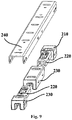
- FIG. 8 is a schematic diagram of a matching of a positioning assembly 200 and the rail assembly 510 of the installation device 100 for the built-in refrigerator 10 according to an embodiment of the present invention, wherein the positioning assembly 200 is a general term for the fixing frame 240, the guide block and the pulley assembly 220; and FIG. 9 is an exploded view of the positioning assembly 200 of the installation device 100 for the built-in refrigerator 10 shown in FIG. 8 .
- the installation device 100 for the built-in refrigerator 10 is used for installing the refrigerator 10 into the installation space in the cabinet 20.
- the installation device 100 may generally include the fixing frame 240 and at least one guide block, and may further include a plurality of pulley assemblies 220 and a plurality of leveling feet 300.
- a bottom pulley can be used for freely moving.
- the fixing frame 240, at least one guide block and the plurality of pulley assemblies 220 can be integrated to form the positioning assembly 200, and after the positioning assembly 200 is formed, the fixing frame 240, the guide block and the plurality of pulley assemblies 220 can be entirely installed at the bottom of the refrigerator 10 at one time, improving the assembly efficiency of the refrigerator 10.
- the number of the built-in refrigerator 10 may be two, and the number of the positioning assembly 200 may be two, wherein one positioning assembly 200 is arranged on one refrigerator 10; the number of the leveling foot 300 may be four, the leveling feet 300 being disposed on the front side of front pulleys 600 of the two refrigerators 10 respectively.
- the fixing frame 240 is disposed on a bottom plate of the refrigerator 10 in a front-back extension direction of the refrigerator 10.
- the fixing frame 240 can adjoin a lateral perimeter of the bottom plate of the refrigerator 10.
- the fixing frame 240 has a first connecting plate for being connected and fixed to the bottom of the refrigerator 10 and second connecting plates formed extending downward from the two lateral ends of the first connecting plate, making the cross section of the fixing frame 240 be in an inverted U shape, and limiting an enclosure cavity in the fixing frame 240.
- the enclosure cavity is used for accommodating the below guide block and a plurality of pulley assemblies 220.
- the number of the second connecting plate is two, and the second connecting plate close to the lateral perimeter of the bottom plate of the refrigerator 10 and the side plate of the refrigerator 10 are kept flush, that is, the second connecting plate close to the lateral perimeter of the bottom plate of the refrigerator 10 is within the same plane as the side plate of the refrigerator 10.
- the fixing frame 240, the front pulley 600 and the back pulley 700 are all disposed on the bottom plate of the refrigerator 10, wherein the front pulley 600 is located on a front side of the fixing frame 240, and the back pulley 700 is located on an inner side of the fixing frame 240.
- the inner side refers to, relative to the fixing frame 240, the back pulley 700 is away from the lateral perimeter of the bottom plate of the refrigerator 10.
- the above limiting plate may abut against the second connecting plate of the fixing frame 240 close to the lateral perimeter of the bottom plate of the refrigerator 10 and the side plate of the refrigerator 10, and the positioning strip 522 may abut against another side plate of the refrigerator 10, so that the side plate of the refrigerator 10 can keep parallel to the side wall of the cabinet 20 all the time when the refrigerator 10 moves or after the refrigerator 10 reaches the specified installation position.
- the limiting plate, the positioning strip 522 and the fixing frame 240 provide a structure foundation when the refrigerator 10 moves along a straight line.
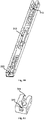
- FIG. 10 is another schematic diagram of the positioning assembly 200 of the installation device 100 of the built-in refrigerator 10 shown in FIG. 8 .
- At least one guide block disposed on the fixing frame 240, wherein the bottom of the guide block is provided with the groove 212 parallel to the front-back extension direction of the refrigerator 10, and the groove 212 is configured to match the guide rail portion 512 pre-installed on the ground where the installation space is located, to limit the refrigerator 10 to move in the front-back direction.
- the number of the guide block is more than one, the blocks are disposed at intervals along the fixing frame 240, and grooves 212 of the plurality of guide blocks are at a same straight line parallel to the front-back extension direction of the refrigerator 10.
- the shape of the guide rail portion 512 can adapt to that of the groove 212 to make the guide rail portion 512 located inside the groove 212 when the refrigerator 10 moves, and to make the refrigerator 10 be capable of moving backward in a straight line when the guide block moves on the guide rail portion 512.
- the above installation device 100 and the auxiliary installation assembly 500 are used to enable the refrigerator 10 to move backward along a preset path in a straight line to the installation position, the operation is simple, time-saving and labor-saving, avoiding the problem that in a moving process, due to uneven stress, the box body of the refrigerator 10 is skewed, moves forward in a winding manner, and can hardly get in and out of the installation space, and reducing the installation difficulty of the built-in refrigerator 10.
- the installation device 100 and the auxiliary installation assembly 500 mutually match to enable the built-in refrigerator 10 to move to the installation position along the preset path, so that the refrigerator 10 can be moved in one step, thereby avoiding repeatedly adjusting the position of the refrigerator 10 in the process of installation, improving an installation efficiency of the built-in refrigerator 10, and achieving a quick installation of the built-in refrigerator 10.
- FIG. 11 is a schematic diagram of a first guide block 210 of the positioning assembly 200 of the installation device 100 for the built-in refrigerator 10 shown in FIG. 10 .
- a plurality of guide blocks includes: the first guide block 210, located at the back end of the fixing frame 240.
- the back portion of the first guide block 210 is formed with a bell mouth 211 expanding backward from a lateral side wall of the groove 212, and the bell mouth 211 is configured to be assembled with one side of the guide rail portion 512 that faces the outside of an installation space, to guide the refrigerator 10 onto the guide rail portion 512.
- the bell mouth 211 is formed by gradually expanding and extending backward of two side walls at two lateral ends of the groove 212, and is a bell-shaped access port, so that the bell mouth 211 can be used to guide the refrigerator 10 onto the guide rail portion 512.
- the guide block When the refrigerator 10 moves to the front side of the installation space, the guide block is located on the front side of the guide rail portion 512, and because the opening of the bell mouth 211 is relatively large, as long as it is ensured that the guide rail portion 512 is located within the bell mouth 211 and the refrigerator 10 is pushed backward continuously, the guide rail portion 512 can enter the groove 212, so that the guide block can be quickly pushed onto the guide rail portion 512 without any precise aiming.
- the height and shape of the guide rail portion 512 may adapt to the depth and shape of the groove 212 to enable the guide block to engage with the guide rail portion 512 by means of the groove 212, so that when the refrigerator 10 moves, the guide block is located on the guide rail portion 512 all the time, thereby preventing the refrigerator 10 from deviating from the preset track in the process of moving, and requiring no position adjustment after the refrigerator 10 reaches the specified installation position.
- FIG. 12 is a schematic diagram of the pulley assembly 220 of the positioning assembly 200 of the installation device 100 for the built-in refrigerator 10 shown in FIG. 10 ; and FIG. 13 is an exploded view of the pulley assembly 220 of the positioning assembly 200 of the installation device 100 for the built-in refrigerator 10 shown in FIG. 12 .
- a plurality of pulley assemblies 220 is disposed in the intervals between a plurality of guide blocks and is configured to slide along the surface of a guide rail portion 512 to decrease frictional resistance generated when the refrigerator 10 moves.
- Each of the pulley assembly 220 includes: a plurality of runners 221, a connector 222, a fixing shaft 223 and a cover housing 224.
- the plurality of runners 221 is sequentially arranged in an extension direction of the groove 212, wherein the outer peripheral edge of the runners 221 is formed in a shape matching the top of the guide rail portion 512.
- the number of the runner 221 can be set according to a practical need; for example, the number may be two, three, four or five, and may also be one, and preferably, the number may be two.
- the top of the guide rail portion 512 is formed with an arc-shaped curved surface protruding outward ( relative to the guide rail portion 512), and the outer peripheral edge of the runner 221 is formed with an arc-shaped curved surface concaving inward (relative to the runner 221).
- the number of the guide block may be three, including the first guide block 210 and a second guide block 230, wherein the number of the second guide block 230 may be two, and the second guide blocks 230 are located at the middle and the front side of the fixing frame 240 respectively. That is, in the front-back extension direction of the refrigerator 10 and from the front to the back, the fixing frame 240 is sequentially provided with a second guide block 230, a pulley assembly 220, a second guide block 230, a pulley assembly 220 and the first guide block 210.
- the runner 221 has a central rotating shaft, and the runner 221 rotates circumferentially around the central rotating shaft.
- the runner 221 further includes two wheel body portions disposed on the central rotating shaft in a penetrating manner and a connecting portion located between the two wheel body portions, wherein the connecting portion is formed by gradually contracting inward of peripheral edges of the two wheel body portions in an opposite direction.
- the shape of the top of the guide rail portion 512 may adapt to that of the connecting portion to make the connecting portion of the runner 221 located on the guide rail portion 512 when the refrigerator 10 moves, and the wheel body portion of the runner 221 may be suspendedly disposed, or located on the above bottom plate portion 511.
- the connector 222 has a shaft hole for matching the two ends of a central rotating shaft of each runner 221, so that the central rotating shafts of the plurality of the runners 221 are rotatably connected onto the connector 222.
- the number of the connector 222 may be two, and the connectors 222 are in sheet shapes respectively, parallelly disposed at an interval, and located on the two lateral sides of the plurality of runners 221 respectively, wherein one connector 222 is used for matching the tail end of the central rotating shaft located on the same side of the plurality of runners 221, the number of the shaft hole on each of the connectors 222 can be correspondingly set according to that of the runner 221, and the position of the shaft hole can adapt to the arrangement position of the plurality of runners 221.
- the aperture of the shaft hole may be slightly larger than the outer diameter of the central rotating shaft to prevent the problem that the seizure of the central rotating shaft in the shaft hole causes the runner 221 can not rotate.
- a fixing shaft 223 is disposed between the two connectors 222 in a penetrating manner. That is, the fixing shaft 223 is disposed parallel to the central rotating shaft.
- the number of the runner 221 is two, and the fixing shaft 223 can be located between the two runners 221 for achieving a fixed connection to the connector 222 and the cover housing 224 (as will be described in detail below) to form the pulley assembly 220, so that the pulley assembly 220 is fixedly connected to the fixing frame 240, thereby completing the assembling of the positioning assembly 200.
- the connector 222 may further be provided with a fixing hole for fixed connection to the fixing shaft 223. The fixing shaft 223 can not rotate, because the fixing shaft 223 and the connector 222 are fixedly connected.
- the cover housing 224 is fixedly connected to the two ends of the fixing shaft 223 and is configured to limit the runners 221 in the cover housing 224, wherein the bottom of the cover housing 224 is provided with an opening to allow the runners 221 to be in contact with the surface of the guide rail portion 512.
- the cover housing 224 may cover the runner 221, the connector 222 and the fixing shaft 223 to form the pulley assembly 220.
- the cover housing 224 is further provided with the fixing hole for fixed connection to the fixing shaft 223, that is, the connector 222 combines the plurality of runners 221 into a whole, and the fixing shaft 223 further combines the combination of the connector 222 with the plurality of runners 221 and the cover housing 224 into a whole to simplify the assembling step of the plurality of runners 221.
- the fixing frame 240 can cover the top and the side part of the first guide block 210, the plurality of pulley assemblies 220 and the second guide block 230, and is configured to be connected to a bottom wall of the refrigerator 10 to fix the positioning assembly 200 on the refrigerator 10.
- the first connecting plate can be fixed on the bottom of the refrigerator 10 by means of screw connection.
- a side wall of the guide block can be provided with a plurality of jack catches, and the second connecting plate can be provided with a plurality of slots to make the guide block and the fixing frame 240 combined into a whole by clamping the jack catches and the slots;
- the cover housing 224 can be provided with a screw hole, and the first connecting plate can also be correspondingly provided with a screw hole to fix the pulley assembly 220 on the fixing frame 240 by means of screw connection, thereby forming the positioning assembly 200.
- the pulley assembly 220 can also be connected and fixed to the fixing frame 240 by means of riveting.
- a plurality of leveling feet 300 is disposed at the bottom of a refrigerator 10, is located in front of a front bottom pulley of the refrigerator 10, and is configured to level the refrigerator 10 by adjusting a height thereof.
- each of the refrigerators 10 can be provided with two leveling feet 300, and the leveling feet 300 can have different height by adjusting the height under the action of an installation tool, thereby making the front of the refrigerator 10 elevated or lowered, that is, the front and the back of the refrigerator 10 is kept flush by adjusting the height of the front of the refrigerator 10.
- a gradienter can be used for determining the degree of levelness of the position where the refrigerator 10 is located.
- the pad 530 is first used to elevate the back portion of the refrigerator 10, and then the leveling feet 300 are used to adjust the height of the front portion of the refrigerator 10, which is convenient and efficient, can quickly adjust the top and bottom of the refrigerator 10 to the same horizontal plane after the refrigerator 10 reaches the installation position, and improves the aesthetics of the built-in refrigerator 10.
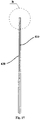
- FIG. 14 is a schematic diagram of an insertion strip 400 and a connecting sheet 800 of the installation device 100 for the built-in refrigerator 10 according to an embodiment of the present invention
- FIG. 15 is another schematic diagram of the insertion strip 400 and the connecting sheet 800 of the installation device 100 for the built-in refrigerator 10 shown in FIG. 14
- FIG. 16 is a partial enlarged view of part B in FIG. 15 .
- the installation device 100 further includes: the insertion strip 400 connected between the two refrigerators 10, and the connecting sheet 800 for connecting and fixing each of the refrigerators 10 and the insertion strip 400.
- the insertion strip 400 can be used for shading a gap between the two refrigerators 10 to increase the aesthetics; the connecting sheet 800 can prevent the two refrigerators 10 from producing relative displacement to increase installation stability.
- the insertion strip 400 has an insertion surface 410 kept flush with a front plate of the refrigerator 10 and having the same height as the front plate of the refrigerator 10, and an insertion wall 420 extending backward from the insertion surface 410 in a direction perpendicular to the insertion surface 410.
- the insertion surface 410 shades the gap between the two refrigerators 10 to make a modular refrigerator 10 keep aesthetic.
- the number of the insertion wall 420 is two, and the insertion walls 420 are parallelly disposed in an interval to make each of the insertion walls 420 disposed with a side plate of one refrigerator 10 in an abutting manner respectively.
- the installation device 100 further includes: at least one magnetic plaster, wherein the magnetic plaster may be located between the insertion wall 420 and the side plate of the refrigerator 10 to increase the adhesive force between the side plate of the refrigerator 10 and the insertion wall 420, so that the position stability of the modular refrigerator 10 can be improved when the modular refrigerator 10 is used, thereby reducing or avoiding the absolute displacement or relative displacement happening when the refrigerator 10 is used.
- the above installation device 100 and an auxiliary installation assembly 500 can also achieve a quick installation of one refrigerator 10 or the plurality of modular refrigerators 10.
- the installation device 100 for the built-in refrigerator 10 includes a guide block, wherein the bottom of the guide block is provided with a groove 212 parallel to the front-back extension direction of the refrigerator 10, and the groove 212 is configured to match with a guide rail portion 512 pre-installed on the ground where the installation space is located to limit the refrigerator 10 to move in the front-back direction, so that the refrigerator 10 can move backward along a preset path to the installation position, the operation is simple, time-saving and labor-saving, avoiding the problem that in a moving process, due to uneven stress, the box body of the refrigerator 10 is skewed, moves forward in a winding manner, and can hardly get in and out of the installation space, and reducing the installation difficulty of the built-in refrigerator 10.
Landscapes
- Engineering & Computer Science (AREA)
- Chemical & Material Sciences (AREA)
- Combustion & Propulsion (AREA)
- Physics & Mathematics (AREA)
- Mechanical Engineering (AREA)
- Thermal Sciences (AREA)
- General Engineering & Computer Science (AREA)
- Refrigerator Housings (AREA)
Abstract
Description
- The present invention relates to the field of refrigerators, and in particular to a built-in refrigerator, and an installation device and an auxiliary installation assembly therefor.
- Installing a built-in refrigerator demands embedding a box body into a reserved installation space in a household cabinet. However, because the volume of the installation space is approximately equal to that of the box body, in the process of the installation, the user can only apply acting force on the front side of the box body to push the box body into the installation space. In the process of moving the box body, it is greatly easy to result in problems that the box body skews and moves in a winding manner due to uneven stress, making the entire process of installation very difficult.
- Therefore, how to reduce the installation difficulty of a built-in refrigerator becomes a technical problem to be urgently solved by those skilled in the art.
- An object of the present invention is to provide a built-in refrigerator, and an installation device and an auxiliary installation assembly therefor which are capable of at least solving any one of the aspects in the above technical problem.
- A further object of the present invention is to enable the built-in refrigerator to get in and out of the installation space in a fixed direction, so that the installation difficulty of the built-in refrigerator is reduced.
- A further object of the present invention is to achieve a quick installation of the built-in refrigerator.
- A further object of the present invention is to reinforce the integrity between the built-in refrigerator and a cabinet.
- A further object of the present invention is to improve the installation aesthetics of the built-in refrigerator.
- According to an aspect of the present invention, an installation device for a built-in refrigerator is provided, and is used for installing the built-in refrigerator into an installation space in a cabinet. The installation device includes: a fixing frame, disposed on a bottom plate of the refrigerator in a front-back extension direction of the refrigerator; and at least one guide block, disposed on the fixing frame, wherein the bottom of the guide block is provided with a groove parallel to the front-back extension direction of the refrigerator, and the groove is configured to match a guide rail portion pre-installed on the ground where the installation space is located, to limit the refrigerator to move in the front-back direction.
- Optionally, the number of the guide block is more than one, the guide blocks being disposed at intervals along the fixing frame, and grooves of the plurality of the guide blocks are at a same straight line parallel to the front-back extension direction of the refrigerator.
- Optionally, the plurality of guide blocks includes: a first guide block, located at the back end of the fixing frame;
the back portion of the first guide block is formed with a bell mouth expanding backward from a lateral side wall of the groove, and the bell mouth is configured to be assembled with one side of the guide rail portion that faces the outside of the installation space, to guide the refrigerator onto the guide rail portion. - Optionally, the installation device further includes a plurality of pulley assemblies disposed in the intervals between the plurality of guide blocks and configured to slide along the surface of the guide rail portion to decrease frictional resistance generated when the refrigerator moves.
- Optionally, the pulley assembly include: a plurality of runners sequentially arranged in an extension direction of the groove, wherein the outer peripheral edge of the runners is formed in a shape matching the top end of the guide rail portion; and a connector having a shaft hole for matching the two ends of a central rotating shaft of each runner, so that the central rotating shaft of the plurality of runners is rotatably connected onto the connector.
- Optionally, the number of the connectors is two, the connectors are respectively on two lateral sides of the plurality of runners, and the pulley assembly further include: a fixing shaft disposed between the two connectors in a penetrating manner; and a cover housing fixedly connected to the two ends of the fixing shaft and configured to limit the runners in the cover housing, wherein the bottom of the cover housing is provided with an opening to allow the runners to be in contact with the surface of the guide rail portion.
- Optionally, the installation device further includes a plurality of leveling feet disposed at the bottom of the refrigerator, located in front of a front bottom pulley of the refrigerator, and configured to level the refrigerator by adjusting a height thereof.
- According to another aspect of the present invention, a built-in refrigerator is further provided, including: a box body; and the installation device as described in any one of the foregoing items disposed at the bottom of the box body.
- According to still another aspect of the present invention, an auxiliary installation assembly for a built-in refrigerator is further provided to install a refrigerator into an installation space in a cabinet, the auxiliary installation assembly including:
a rail assembly configured to at least be disposed on a lateral side of the ground where the installation space is located, and configured to be disposed in a front-back extension direction of the ground, to allow the refrigerator to get in and out of the installation space in the front-back direction, and the rail assembly includes: a bottom plate portion, configured to be laid on the ground; and a guide rail portion formed extending upward from the surface of the bottom plate portion and configured to allow a guide block of the installation device as described in any one of the foregoing items to move along the surface thereof. - Optionally, the rail assembly further includes: a limiting portion formed extending upward from the surface of the bottom plate portion and disposed parallel to the guide rail portion at an interval; the auxiliary installation assembly further includes: a positioning member configured to be disposed on the ground parallel to an extension direction of the rail assembly, and having a positioning strip parallel to the limiting portion, wherein the guide rail portion is located between the positioning strip and the limiting portion, and the positioning member is further configured to match the limiting portion to adjust a moving path of the refrigerator when the guide block deviates from the guide rail portion; and a pad located between the rail assembly and the positioning member and configured to elevate a back bottom pulley of the refrigerator when the refrigerator moves to an installation position.
- According to a built-in refrigerator, an installation device and an auxiliary installation assembly therefor of the present invention, the installation device for the built-in refrigerator includes a guide block, wherein the bottom of the guide block is provided with a groove parallel to a front-back extension direction of the refrigerator, and the groove is configured to match with a guide rail portion pre-installed on the ground where the installation space is located to limit the refrigerator to move in the front-back direction, so that the refrigerator can move backward along a preset path to the installation position, the operation is simple, time-saving and labor-saving, avoiding the problem that in a moving process, due to uneven stress, the box body of the refrigerator is skewed, moves forward in a winding manner, and can hardly get in and out of the installation space, and reducing the installation difficulty of the built-in refrigerator.
- Further, according to the built-in refrigerator, the installation device and the auxiliary installation assembly therefor of the present invention, with a mutual matching of the installation device and the auxiliary installation assembly, the built-in refrigerator can move to the installation position along the preset path, so that the refrigerator can be moved in one step, thereby avoiding repeatedly adjusting the position of the refrigerator in the process of installation, improving an installation efficiency of the built-in refrigerator, and achieving a quick installation of the built-in refrigerator.
- Further, according to the built-in refrigerator, the installation device and the auxiliary installation assembly therefor of the present invention, the position of the auxiliary installation assembly on the ground where the installation space is located can be adjusted to adjust the size of a gap between the refrigerator and the side wall of the cabinet as well as the refrigerator and the back wall of the cabinet, so that the refrigerator and the cabinet are kept flush, reinforcing the integrity between the built-in refrigerator and the cabinet.
- Further, according to the built-in refrigerator, the installation device and the auxiliary installation assembly therefor of the present invention, the auxiliary installation assembly includes a pad pre-installed on the ground and configured to elevate the back portion of the refrigerator when the refrigerator moves to an installation position; the installation device further includes a plurality of leveling feet disposed at the bottom of the refrigerator and configured to level the refrigerator by adjusting a height thereof, wherein the pad is first used to elevate the back portion of the refrigerator, and then the leveling feet are used to adjust the height of the front portion of the refrigerator, which is convenient and efficient, can quickly adjust the top and bottom of the refrigerator to the same horizontal plane after the refrigerator reaches the installation position, improving the aesthetics of the built-in refrigerator.
- Specific embodiments of the present invention will be described in detail below with reference to the accompanying drawings, and those skilled in the art will better understand the above and other objectives, advantages and features of the present invention.
- Hereinafter, some specific embodiments of the present invention will be described in detail in an exemplary rather than restrictive manner with reference to the accompanying drawings. In the drawings, like reference numerals denote like or similar components or parts. Those skilled in the art should understand that these drawings are not necessarily drawn to scale. In the figures:
-
FIG. 1 is an assembly view of a built-in refrigerator according to an embodiment of the present invention; -
FIG. 2 is a left view of a built-in refrigerator according to an embodiment of the present invention; -
FIG. 3 is a partial enlarged view of part A inFIG. 2 ; -
FIG. 4 is a bottom view of a built-in refrigerator shown inFIG. 2 ; -
FIG. 5 is a schematic diagram of an auxiliary installation assembly for a built-in refrigerator according to an embodiment of the present invention; -
FIG. 6 is a schematic diagram of a rail assembly of the auxiliary installation assembly for the built-in refrigerator shown inFIG. 5 ; -
FIG. 7 is a schematic diagram of a positioning member of the auxiliary installation assembly for the built-in refrigerator shown inFIG. 5 ; -
FIG. 8 is a schematic diagram of a matching of a positioning assembly and a rail assembly of an installation device for a built-in refrigerator according to an embodiment of the present invention, wherein the positioning assembly is a general term for a fixing frame, a guide block and a pulley assembly; -
FIG. 9 is an exploded view of the positioning assembly of the installation device for the built-in refrigerator shown inFIG. 8 ; -
FIG. 10 is another schematic diagram of the positioning assembly of the installation device for the built-in refrigerator shown inFIG. 8 ; -
FIG. 11 is a schematic diagram of a first guide block of the positioning assembly of the installation device for the built-in refrigerator shown inFIG. 10 ; -
FIG. 12 is a schematic diagram of a pulley assembly of the positioning assembly of the installation device for the built-in refrigerator shown inFIG. 10 ; -
FIG. 13 is an exploded view of the pulley assembly of the positioning assembly of the installation device for the built-in refrigerator shown inFIG. 12 ; -
FIG. 14 is a schematic diagram of an insertion strip and a connecting sheet of an installation device for a built-in refrigerator according to an embodiment of the present invention; -
FIG. 15 is another schematic diagram of the insertion strip and the connecting sheet of the installation device for the built-in refrigerator shown inFIG. 14 ; and -
FIG. 16 is a partial enlarged view of part B inFIG. 15 . -
FIG. 1 is an assembly view of a built-inrefrigerator 10 according to an embodiment of the present invention;FIG. 2 is a left view of a built-inrefrigerator 10 according to an embodiment of the present invention;FIG. 3 is a partial enlarged view of part A inFIG. 2 ; andFIG. 4 is a bottom view of the built-inrefrigerator 10 shown inFIG. 2 . - The built-in refrigerator 10 (hereinafter referred to as "refrigerator") may generally include: a box body and an
installation device 100 disposed at the bottom of the box body. In this embodiment, the bottom of therefrigerator 10 may be pre-installed with a bottom pulley, and the number of the bottom pulley may be four, the bottom pulley including twofront pulleys 600 and twoback pulleys 700. Theinstallation device 100 for the built-inrefrigerator 10 is used for installing therefrigerator 10 into acabinet 20, and an installation space of therefrigerator 10 is formed in thecabinet 20. The cuboid-shaped installation space is enclosed jointly by a back wall, a side wall and a top wall of thecabinet 20 as well as the ground where the installation space is located. An installation position of therefrigerator 10 refers to a specific position of therefrigerator 10 in the installation space. - The installation space can accommodate the
single refrigerator 10, and can also accommodate themodular refrigerator 10 in any quantity, and the specific arrangement plan can be determined according to a practical need. In this embodiment, the installation space can accommodate twomodular refrigerators 10 which can be parallelly disposed in a lateral extension direction of the installation space. -
FIG. 5 is a schematic diagram of anauxiliary installation assembly 500 for the built-inrefrigerator 10 according to an embodiment of the present invention. - The built-in
refrigerator 10 may further include theauxiliary installation assembly 500. Theauxiliary installation assembly 500 for a built-inrefrigerator 10 is used for installing therefrigerator 10 into an installation space in acabinet 20. - The
auxiliary installation assembly 500 is configured to be pre-installed on the ground where the installation space is located, is used for assisting in limiting a moving path and an installation position of therefrigerator 10, and is further used for assisting in leveling therefrigerator 10. Theauxiliary installation assembly 500 includes: arail assembly 510, apositioning member 520 and apad 530. -
FIG. 6 is a schematic diagram of arail assembly 510 of theauxiliary installation assembly 500 for the built-inrefrigerator 10 shown inFIG. 5 . - The
rail assembly 510 is configured to at least be disposed on a lateral side of the ground where the installation space is located, and is configured to be disposed in a front-back extension direction of the ground, to allow therefrigerator 10 to get in and out of the installation space in the front-back direction. In this embodiment, the number of the built-inrefrigerator 10 is two, and the number of therail assembly 510 may be two; therail assemblies 510 are used for being pre-installed on the lateral side of the above ground respectively, and are used for limiting the moving path and the installation position of eachrefrigerator 10. In some alternative embodiments, the number of the built-inrefrigerator 10 is one, and the number of therail assembly 510 may be one, or may be two. Therail assembly 510 can be fixed on the ground by means of screw connection or adhesion. Therail assembly 510 includes abottom plate portion 511, aguide rail portion 512 and a limitingportion 513. - In this embodiment, the definitions of the
auxiliary installation assembly 500 and terms "front", "rear", "back", "side", "top", and the like used to indicate the orientation or positional relationship are relative to the actual usage state of theauxiliary installation assembly 500 on the ground where the installation space is located. The definitions of aninstallation device 100 and terms "front", "rear", "back", "side", "top", and the like used to indicate the orientation or positional relationship are relative to the actual usage state of therefrigerator 10 in the installation space. - The
bottom plate portion 511 is configured to be laid on the ground. According to therail assembly 510, thebottom plate portion 511 can be connected on the ground by screw or adhesive on the ground to achieve the integral fixing of therail assembly 510. Thebottom plate portion 511 may be in a rectangular plate shape extending from the front to the back in parallel to the front-back extension direction of the ground. A side of thebottom plate portion 511 close to a side wall of acabinet 20 can be disposed by abutting against the side wall of thecabinet 20. A side of thebottom plate portion 511 close to a back wall of thecabinet 20 may be spaced at a preset distance from the back wall of thecabinet 20, and the size of the preset distance can be set according to a practical need, so that a gap with a determined size can be formed between a wall plate of therefrigerator 10 and the back wall of thecabinet 20. - The
guide rail portion 512 is formed extending upward from the surface of thebottom plate portion 511 and is configured to allow a guide block of theinstallation device 100 mentioned below to move along the surface thereof. That is, theguide rail portion 512 forms a moving track of the guide block. In this embodiment, theguide rail portion 512 forms a moving track of the guide block and apulley assembly 220. Theguide rail portion 512 may be in a plate shape, be perpendicular to thebottom plate portion 511, and be disposed parallel to the front-back extension direction of the ground. - The
guide rail portion 512 keeps parallel to the side wall of thecabinet 20 to enable therefrigerator 10, in the process of moving into the installation position from the front to the back, to keep parallel to the side wall of thecabinet 20 all the time, so that the size of the gap does not need to be adjusted again repeatedly between therefrigerator 10 and the side wall of thecabinet 20 after therefrigerator 10 reaching the installation position, improving an installation efficiency. - To reduce the resistance appearing when the
refrigerator 10 moves, the part of theguide rail portion 512 in contact with agroove 212 of the guide block can be set as a smooth curved surface, so that the curved surface and thegroove 212 of the guide block can mutually match to reduce the reduce the frictional resistance appearing when therefrigerator 10 moves. - A side of the
guide rail portion 512 close to the back wall of thecabinet 20 may be provided with a stopper for preventing therefrigerator 10 from moving backward after reaching theinstallation device 100, thereby making therefrigerator 10 stop moving. After stopping moving, therefrigerator 10 reaches a specified installation position. The stopper may be spaced a fixed distance from the back wall of thecabinet 20, and the length of the fixed distance can be set according to a practical need, so that a gap with a determined size can be formed between a back plate of therefrigerator 10 and the back wall of thecabinet 20. - The above
auxiliary installation assembly 500 of the present embodiment not only provides a preset moving track for therefrigerator 10 to ensure that therefrigerator 10 performs a linear motion along the preset path to move to the installation position, but also can enable therefrigerator 10 to reach the installation position specified by a user, and provide a gap between therefrigerator 10 and thecabinet 20, wherein the size of the gap can be adjusted by adjusting the position of theauxiliary installation assembly 500, improving the installation flexibility of therefrigerator 10. - The limiting
portion 513 is formed extending upward from the surface of thebottom plate portion 511, and is disposed parallel to theguide rail portion 512 at an interval. The limitingportion 513 is higher than theguide rail portion 512, and is further configured to be parallel to the side wall of thecabinet 20, and to adjoin the side wall of therefrigerator 10 and a fixingframe 240 of theinstallation device 100 when therefrigerator 10 moves, so as to adjust the moving path of therefrigerator 10 when the guide block deviates from theguide rail portion 512. That is, the limitingportion 513 is used for preventing the guide block from disengaging from theguide rail portion 512, and the limitingportion 513 cooperates with theguide rail portion 512 so that the guide block moves from the front to the back strictly in a direction parallel to the side wall of thecabinet 20. In this embodiment, the limitingportion 513 may be in a plate shape, be perpendicular to thebottom plate portion 511, and be disposed in a front-back extension direction of the ground. On thebottom plate portion 511, the limitingportion 513 may be on the side of thebottom plate portion 511 close to the side wall of thecabinet 20, and theguide rail portion 512 may be on the side of thebottom plate portion 511 away from the side wall of theabove cabinet 20. The limitingportion 513 may be spaced at a set distance from the side wall of thecabinet 20, and the length of the set distance can be set according to a practical need, so that the gap with a determined size can be formed between a side plate of therefrigerator 10 and the side wall of thecabinet 20. - When the
refrigerator 10 moves, thegroove 212 of the guide block can be engaged with theguide rail portion 512, and the surface of the guide block that faces the side wall of thecabinet 20 can further abut against the limitingportion 513, theguide rail portion 512 and the limitingportion 513 mutually match to strictly limit the moving path of therefrigerator 10, to enable therefrigerator 10 to reach the specified installation position along the preset path, and at the same time, after therefrigerator 10 reaches the installation position, to provide gaps with a determined size between therefrigerator 10 and the side wall of thecabinet 20 as well as therefrigerator 10 and the back wall of thecabinet 20, so that the position of therefrigerator 10 does not need to be repeatedly adjusted after therefrigerator 10 reaches the installation position, which is simple, convenient and quick, easy to realize, time-saving and labor-saving, and improves an installation efficiency of the built-inrefrigerator 10. -
FIG. 7 is a schematic diagram of apositioning member 520 of theauxiliary installation assembly 500 shown inFIG. 5 . - The positioning
member 520 is configured to be disposed on the ground parallel to an extension direction of arail assembly 510, and has apositioning strip 522 parallel to the limitingportion 513, wherein aguide rail portion 512 is located between thepositioning strip 522 and the limitingportion 513, and thepositioning member 520 is further configured to match the limitingportion 513 to adjust the moving path of therefrigerator 10 when the guide portion deviates from theguide rail portion 512. The positioningmember 520 has apositioning plate 521 laid on the ground and apositioning strip 522 formed extending upward from the surface of thepositioning plate 521. Thepositioning strip 522 is parallel to a side wall of acabinet 20. In this embodiment, the positioningmember 520 can be pre-installed on the ground, when the above installation space is used for installing twomodular refrigerators 10, the positioningmember 520 can be located between the above tworail assemblies 510; for example, the positioningmember 520 can be located at the position between the above tworail assemblies 510 for mutually matching therail assemblies 510 to limit the moving path of the twomodular refrigerators 10. For therefrigerator 10 at an installation position, therail assembly 510 is at a lateral end of the bottom of therefrigerator 10, while thepositioning member 520 is at another lateral end of the bottom of therefrigerator 10. Thepositioning plate 521 may be in a rectangular plate shape, and is configured to extend from the front to the back along the lateral extension direction of the ground. Thepositioning strip 522 may be in a plate shape, be perpendicular to thepositioning plate 521, and be disposed parallel to the front-back extension direction of the ground. When therefrigerator 10 moves or after therefrigerator 10 reaches the installation position, thepositioning strip 522 has a surface facing the side plate of onerefrigerator 10 and another surface facing the side plate of anotherrefrigerator 10. - The distance between the
positioning strip 522 and the limitingportion 513 of therail assembly 510 can be set according to a practical need, for example, the length of the distance can fit with a lateral dimension of the box body of therefrigerator 10, so that thepositioning strip 522 and therail assembly 510 can mutually match to limit the installation position and the moving path of therefrigerator 10. - By adjusting the position of the
auxiliary installation assembly 500 on the ground where the installation space is located, the size of gaps can be adjusted between therefrigerator 10 and the side wall of thecabinet 20 as well as therefrigerator 10 and the back wall of thecabinet 20, so that therefrigerator 10 and thecabinet 20 are kept flush, reinforcing the integrity between the built-inrefrigerator 10 and thecabinet 20. - The
pad 530 is located between therail assembly 510 and thepositioning member 520, and is configured to elevate a back bottom pulley (i.e. a back pulley 700) of therefrigerator 10 when therefrigerator 10 moves to the installation position to make the refrigerator slightly forward incline, that is, when therefrigerator 10 moves to the installation position, thepad 530 makes the back of therefrigerator 10 higher than the front of therefrigerator 10, and in this way, therefrigerator 10 can be leveled only by adjusting the height of the front of therefrigerator 10. In this embodiment, the number of thepad 530 may be more than one, and the number thereof can be set according to that of theback pulley 700 of therefrigerator 10; for example, the number of therefrigerator 10 of the present embodiment is two, the number of theback pulley 700 is four, the number of thepad 530 may be four, and thepads 530 can be pre-installed on the back of the above ground, and be used for elevating the fourback pulleys 700 of the tworefrigerators 10 respectively. Each of thepad 530 may have a slope surface with a height gradually increasing in a backward extension direction and a platform extending backward in a horizontal direction from the top of the slope surface, wherein one platform is used for elevating oneback pulley 700 of therefrigerator 10. The inclination and the length of the slope surface determine the height of theback pulley 700 of therefrigerator 10 elevated by thepad 530. When therefrigerator 10 moves, theback pulley 700 moves up to the platform along the slope surface, reducing the difficulty of elevating theback pulley 700 of therefrigerator 10. -
FIG. 8 is a schematic diagram of a matching of apositioning assembly 200 and therail assembly 510 of theinstallation device 100 for the built-inrefrigerator 10 according to an embodiment of the present invention, wherein thepositioning assembly 200 is a general term for the fixingframe 240, the guide block and thepulley assembly 220; andFIG. 9 is an exploded view of thepositioning assembly 200 of theinstallation device 100 for the built-inrefrigerator 10 shown inFIG. 8 . - The
installation device 100 for the built-inrefrigerator 10 is used for installing therefrigerator 10 into the installation space in thecabinet 20. Theinstallation device 100 may generally include the fixingframe 240 and at least one guide block, and may further include a plurality ofpulley assemblies 220 and a plurality of levelingfeet 300. When therefrigerator 10 is used as aindependent refrigerator 10, a bottom pulley can be used for freely moving. The fixingframe 240, at least one guide block and the plurality ofpulley assemblies 220 can be integrated to form thepositioning assembly 200, and after thepositioning assembly 200 is formed, the fixingframe 240, the guide block and the plurality ofpulley assemblies 220 can be entirely installed at the bottom of therefrigerator 10 at one time, improving the assembly efficiency of therefrigerator 10. - In this embodiment, the number of the built-in
refrigerator 10 may be two, and the number of thepositioning assembly 200 may be two, wherein onepositioning assembly 200 is arranged on onerefrigerator 10; the number of the levelingfoot 300 may be four, the levelingfeet 300 being disposed on the front side offront pulleys 600 of the tworefrigerators 10 respectively. - The fixing
frame 240 is disposed on a bottom plate of therefrigerator 10 in a front-back extension direction of therefrigerator 10. The fixingframe 240 can adjoin a lateral perimeter of the bottom plate of therefrigerator 10. The fixingframe 240 has a first connecting plate for being connected and fixed to the bottom of therefrigerator 10 and second connecting plates formed extending downward from the two lateral ends of the first connecting plate, making the cross section of the fixingframe 240 be in an inverted U shape, and limiting an enclosure cavity in the fixingframe 240. The enclosure cavity is used for accommodating the below guide block and a plurality ofpulley assemblies 220. The number of the second connecting plate is two, and the second connecting plate close to the lateral perimeter of the bottom plate of therefrigerator 10 and the side plate of therefrigerator 10 are kept flush, that is, the second connecting plate close to the lateral perimeter of the bottom plate of therefrigerator 10 is within the same plane as the side plate of therefrigerator 10. The fixingframe 240, thefront pulley 600 and theback pulley 700 are all disposed on the bottom plate of therefrigerator 10, wherein thefront pulley 600 is located on a front side of the fixingframe 240, and theback pulley 700 is located on an inner side of the fixingframe 240. The inner side refers to, relative to the fixingframe 240, theback pulley 700 is away from the lateral perimeter of the bottom plate of therefrigerator 10. - When the
refrigerator 10 moves, the above limiting plate may abut against the second connecting plate of the fixingframe 240 close to the lateral perimeter of the bottom plate of therefrigerator 10 and the side plate of therefrigerator 10, and thepositioning strip 522 may abut against another side plate of therefrigerator 10, so that the side plate of therefrigerator 10 can keep parallel to the side wall of thecabinet 20 all the time when therefrigerator 10 moves or after therefrigerator 10 reaches the specified installation position. The limiting plate, thepositioning strip 522 and the fixingframe 240 provide a structure foundation when therefrigerator 10 moves along a straight line. -
FIG. 10 is another schematic diagram of thepositioning assembly 200 of theinstallation device 100 of the built-inrefrigerator 10 shown inFIG. 8 . - At least one guide block, disposed on the fixing
frame 240, wherein the bottom of the guide block is provided with thegroove 212 parallel to the front-back extension direction of therefrigerator 10, and thegroove 212 is configured to match theguide rail portion 512 pre-installed on the ground where the installation space is located, to limit therefrigerator 10 to move in the front-back direction. The number of the guide block is more than one, the blocks are disposed at intervals along the fixingframe 240, andgrooves 212 of the plurality of guide blocks are at a same straight line parallel to the front-back extension direction of therefrigerator 10. - The shape of the
guide rail portion 512 can adapt to that of thegroove 212 to make theguide rail portion 512 located inside thegroove 212 when therefrigerator 10 moves, and to make therefrigerator 10 be capable of moving backward in a straight line when the guide block moves on theguide rail portion 512. - According to the built-in
refrigerator 10 of the present embodiment, theabove installation device 100 and theauxiliary installation assembly 500 are used to enable therefrigerator 10 to move backward along a preset path in a straight line to the installation position, the operation is simple, time-saving and labor-saving, avoiding the problem that in a moving process, due to uneven stress, the box body of therefrigerator 10 is skewed, moves forward in a winding manner, and can hardly get in and out of the installation space, and reducing the installation difficulty of the built-inrefrigerator 10. - The
installation device 100 and theauxiliary installation assembly 500 mutually match to enable the built-inrefrigerator 10 to move to the installation position along the preset path, so that therefrigerator 10 can be moved in one step, thereby avoiding repeatedly adjusting the position of therefrigerator 10 in the process of installation, improving an installation efficiency of the built-inrefrigerator 10, and achieving a quick installation of the built-inrefrigerator 10. -
FIG. 11 is a schematic diagram of afirst guide block 210 of thepositioning assembly 200 of theinstallation device 100 for the built-inrefrigerator 10 shown inFIG. 10 . - A plurality of guide blocks includes: the
first guide block 210, located at the back end of the fixingframe 240. The back portion of thefirst guide block 210 is formed with abell mouth 211 expanding backward from a lateral side wall of thegroove 212, and thebell mouth 211 is configured to be assembled with one side of theguide rail portion 512 that faces the outside of an installation space, to guide therefrigerator 10 onto theguide rail portion 512. That is, thebell mouth 211 is formed by gradually expanding and extending backward of two side walls at two lateral ends of thegroove 212, and is a bell-shaped access port, so that thebell mouth 211 can be used to guide therefrigerator 10 onto theguide rail portion 512. "Gradually expanding" is relative to "gradually contracting", and thebell mouth 211 is formed by expanding backward of lateral side walls of thegroove 212 means that the size of the cross section opening of thebell mouth 211 is larger than that of the cross section opening of thegroove 212. - When the
refrigerator 10 moves to the front side of the installation space, the guide block is located on the front side of theguide rail portion 512, and because the opening of thebell mouth 211 is relatively large, as long as it is ensured that theguide rail portion 512 is located within thebell mouth 211 and therefrigerator 10 is pushed backward continuously, theguide rail portion 512 can enter thegroove 212, so that the guide block can be quickly pushed onto theguide rail portion 512 without any precise aiming. - The height and shape of the
guide rail portion 512 may adapt to the depth and shape of thegroove 212 to enable the guide block to engage with theguide rail portion 512 by means of thegroove 212, so that when therefrigerator 10 moves, the guide block is located on theguide rail portion 512 all the time, thereby preventing therefrigerator 10 from deviating from the preset track in the process of moving, and requiring no position adjustment after therefrigerator 10 reaches the specified installation position. -
FIG. 12 is a schematic diagram of thepulley assembly 220 of thepositioning assembly 200 of theinstallation device 100 for the built-inrefrigerator 10 shown inFIG. 10 ; andFIG. 13 is an exploded view of thepulley assembly 220 of thepositioning assembly 200 of theinstallation device 100 for the built-inrefrigerator 10 shown inFIG. 12 . - A plurality of
pulley assemblies 220 is disposed in the intervals between a plurality of guide blocks and is configured to slide along the surface of aguide rail portion 512 to decrease frictional resistance generated when therefrigerator 10 moves. Each of thepulley assembly 220 includes: a plurality ofrunners 221, aconnector 222, a fixingshaft 223 and acover housing 224. - The plurality of
runners 221 is sequentially arranged in an extension direction of thegroove 212, wherein the outer peripheral edge of therunners 221 is formed in a shape matching the top of theguide rail portion 512. The number of therunner 221 can be set according to a practical need; for example, the number may be two, three, four or five, and may also be one, and preferably, the number may be two. In this embodiment, the top of theguide rail portion 512 is formed with an arc-shaped curved surface protruding outward ( relative to the guide rail portion 512), and the outer peripheral edge of therunner 221 is formed with an arc-shaped curved surface concaving inward (relative to the runner 221). - In this embodiment, the number of the guide block may be three, including the
first guide block 210 and asecond guide block 230, wherein the number of thesecond guide block 230 may be two, and the second guide blocks 230 are located at the middle and the front side of the fixingframe 240 respectively. That is, in the front-back extension direction of therefrigerator 10 and from the front to the back, the fixingframe 240 is sequentially provided with asecond guide block 230, apulley assembly 220, asecond guide block 230, apulley assembly 220 and thefirst guide block 210. - The
runner 221 has a central rotating shaft, and therunner 221 rotates circumferentially around the central rotating shaft. Therunner 221 further includes two wheel body portions disposed on the central rotating shaft in a penetrating manner and a connecting portion located between the two wheel body portions, wherein the connecting portion is formed by gradually contracting inward of peripheral edges of the two wheel body portions in an opposite direction. The shape of the top of theguide rail portion 512 may adapt to that of the connecting portion to make the connecting portion of therunner 221 located on theguide rail portion 512 when therefrigerator 10 moves, and the wheel body portion of therunner 221 may be suspendedly disposed, or located on the abovebottom plate portion 511. - When the
refrigerator 10 moves from the front to the back under the action of pushing, therunner 221 rotates around the central rotating shaft, and under the rotating action of the plurality ofrunners 221, the frictional resistance appearing when therefrigerator 10 moves can be reduced. - The
connector 222 has a shaft hole for matching the two ends of a central rotating shaft of eachrunner 221, so that the central rotating shafts of the plurality of therunners 221 are rotatably connected onto theconnector 222. In this embodiment, the number of theconnector 222 may be two, and theconnectors 222 are in sheet shapes respectively, parallelly disposed at an interval, and located on the two lateral sides of the plurality ofrunners 221 respectively, wherein oneconnector 222 is used for matching the tail end of the central rotating shaft located on the same side of the plurality ofrunners 221, the number of the shaft hole on each of theconnectors 222 can be correspondingly set according to that of therunner 221, and the position of the shaft hole can adapt to the arrangement position of the plurality ofrunners 221. The aperture of the shaft hole may be slightly larger than the outer diameter of the central rotating shaft to prevent the problem that the seizure of the central rotating shaft in the shaft hole causes therunner 221 can not rotate. - A fixing
shaft 223 is disposed between the twoconnectors 222 in a penetrating manner. That is, the fixingshaft 223 is disposed parallel to the central rotating shaft. In this embodiment, the number of therunner 221 is two, and the fixingshaft 223 can be located between the tworunners 221 for achieving a fixed connection to theconnector 222 and the cover housing 224 (as will be described in detail below) to form thepulley assembly 220, so that thepulley assembly 220 is fixedly connected to the fixingframe 240, thereby completing the assembling of thepositioning assembly 200. Theconnector 222 may further be provided with a fixing hole for fixed connection to the fixingshaft 223. The fixingshaft 223 can not rotate, because the fixingshaft 223 and theconnector 222 are fixedly connected. - The
cover housing 224 is fixedly connected to the two ends of the fixingshaft 223 and is configured to limit therunners 221 in thecover housing 224, wherein the bottom of thecover housing 224 is provided with an opening to allow therunners 221 to be in contact with the surface of theguide rail portion 512. Thecover housing 224 may cover therunner 221, theconnector 222 and the fixingshaft 223 to form thepulley assembly 220. Thecover housing 224 is further provided with the fixing hole for fixed connection to the fixingshaft 223, that is, theconnector 222 combines the plurality ofrunners 221 into a whole, and the fixingshaft 223 further combines the combination of theconnector 222 with the plurality ofrunners 221 and thecover housing 224 into a whole to simplify the assembling step of the plurality ofrunners 221. - The fixing
frame 240 can cover the top and the side part of thefirst guide block 210, the plurality ofpulley assemblies 220 and thesecond guide block 230, and is configured to be connected to a bottom wall of therefrigerator 10 to fix thepositioning assembly 200 on therefrigerator 10. The first connecting plate can be fixed on the bottom of therefrigerator 10 by means of screw connection. A side wall of the guide block can be provided with a plurality of jack catches, and the second connecting plate can be provided with a plurality of slots to make the guide block and the fixingframe 240 combined into a whole by clamping the jack catches and the slots; thecover housing 224 can be provided with a screw hole, and the first connecting plate can also be correspondingly provided with a screw hole to fix thepulley assembly 220 on the fixingframe 240 by means of screw connection, thereby forming thepositioning assembly 200. In some alternative embodiments, thepulley assembly 220 can also be connected and fixed to the fixingframe 240 by means of riveting. - A plurality of leveling
feet 300 is disposed at the bottom of arefrigerator 10, is located in front of a front bottom pulley of therefrigerator 10, and is configured to level therefrigerator 10 by adjusting a height thereof. In this embodiment, each of therefrigerators 10 can be provided with two levelingfeet 300, and the levelingfeet 300 can have different height by adjusting the height under the action of an installation tool, thereby making the front of therefrigerator 10 elevated or lowered, that is, the front and the back of therefrigerator 10 is kept flush by adjusting the height of the front of therefrigerator 10. In this embodiment, a gradienter can be used for determining the degree of levelness of the position where therefrigerator 10 is located. - In this embodiment, the
pad 530 is first used to elevate the back portion of therefrigerator 10, and then the levelingfeet 300 are used to adjust the height of the front portion of therefrigerator 10, which is convenient and efficient, can quickly adjust the top and bottom of therefrigerator 10 to the same horizontal plane after therefrigerator 10 reaches the installation position, and improves the aesthetics of the built-inrefrigerator 10. -
FIG. 14 is a schematic diagram of aninsertion strip 400 and a connectingsheet 800 of theinstallation device 100 for the built-inrefrigerator 10 according to an embodiment of the present invention;FIG. 15 is another schematic diagram of theinsertion strip 400 and the connectingsheet 800 of theinstallation device 100 for the built-inrefrigerator 10 shown inFIG. 14 ; andFIG. 16 is a partial enlarged view of part B inFIG. 15 . - In some alternative embodiments, the
installation device 100 further includes: theinsertion strip 400 connected between the tworefrigerators 10, and the connectingsheet 800 for connecting and fixing each of therefrigerators 10 and theinsertion strip 400. - When the two built-in
refrigerators 10 are required to be installed in an installation space, theinsertion strip 400 can be used for shading a gap between the tworefrigerators 10 to increase the aesthetics; the connectingsheet 800 can prevent the tworefrigerators 10 from producing relative displacement to increase installation stability. - The
insertion strip 400 has aninsertion surface 410 kept flush with a front plate of therefrigerator 10 and having the same height as the front plate of therefrigerator 10, and aninsertion wall 420 extending backward from theinsertion surface 410 in a direction perpendicular to theinsertion surface 410. Theinsertion surface 410 shades the gap between the tworefrigerators 10 to make amodular refrigerator 10 keep aesthetic. The number of theinsertion wall 420 is two, and theinsertion walls 420 are parallelly disposed in an interval to make each of theinsertion walls 420 disposed with a side plate of onerefrigerator 10 in an abutting manner respectively. In some alternative embodiments, theinstallation device 100 further includes: at least one magnetic plaster, wherein the magnetic plaster may be located between theinsertion wall 420 and the side plate of therefrigerator 10 to increase the adhesive force between the side plate of therefrigerator 10 and theinsertion wall 420, so that the position stability of themodular refrigerator 10 can be improved when themodular refrigerator 10 is used, thereby reducing or avoiding the absolute displacement or relative displacement happening when therefrigerator 10 is used. - In some alternative embodiments, the
above installation device 100 and anauxiliary installation assembly 500 can also achieve a quick installation of onerefrigerator 10 or the plurality ofmodular refrigerators 10. - According to a built-in
refrigerator 10, aninstallation device 100 and anauxiliary installation assembly 500 therefor of the present embodiment, theinstallation device 100 for the built-inrefrigerator 10 includes a guide block, wherein the bottom of the guide block is provided with agroove 212 parallel to the front-back extension direction of therefrigerator 10, and thegroove 212 is configured to match with aguide rail portion 512 pre-installed on the ground where the installation space is located to limit therefrigerator 10 to move in the front-back direction, so that therefrigerator 10 can move backward along a preset path to the installation position, the operation is simple, time-saving and labor-saving, avoiding the problem that in a moving process, due to uneven stress, the box body of therefrigerator 10 is skewed, moves forward in a winding manner, and can hardly get in and out of the installation space, and reducing the installation difficulty of the built-inrefrigerator 10. - Thus, it should be appreciated by those skilled in the art that while various exemplary embodiments of the invention have been shown and described in detail herein, many other variations or modifications which are consistent with the principles of the present invention may be determined or derived directly from the disclosure of the present invention without departing from the spirit and scope of the present invention. Accordingly, the scope of the present invention should be understood and interpreted to cover all such other variations or modifications.
Claims (10)
- An installation device for a built-in refrigerator, used for installing the refrigerator into an installation space in a cabinet, the installation device comprising:a fixing frame, disposed on a bottom plate of the refrigerator in a front-back extension direction of the refrigerator; andat least one guide block, disposed on the fixing frame, wherein the bottom of the guide block is provided with a groove parallel to the front-back extension direction of the refrigerator, and the groove is configured to match a guide rail portion pre-installed on the ground where the installation space is located, to limit the refrigerator to move in the front-back direction.
- The installation device according to claim 1, wherein
the number of the guide blocks are more than one, the guide blocks being disposed at intervals along the fixing frame, and grooves of the plurality of guide blocks are at a same straight line parallel to the front-back extension direction of the refrigerator. - The installation device according to claim 2, whereinthe plurality of guide blocks comprises: a first guide block, located at the back end of the fixing frame, whereinthe back portion of the first guide block is formed with a bell mouth expanding backward from a lateral side wall of the groove, and the bell mouth is configured to be assembled with one side of the guide rail portion that faces the outside of the installation space, to guide the refrigerator onto the guide rail portion.
- The installation device according to claim 2, further comprising:
a plurality of pulley assemblies disposed in the intervals between the plurality of guide blocks and configured to slide along the surface of the guide rail portion to decrease frictional resistance generated when the refrigerator moves. - The installation device according to claim 4, wherein the pulley assembly comprise:a plurality of runners sequentially arranged in an extension direction of the groove, wherein the outer peripheral edge of the runners is formed in a shape matching the top end of the guide rail portion; anda connector having a shaft hole for matching the two ends of a central rotating shaft of each runner, so that the central rotating shaft of the plurality of runners is rotatably connected onto the connector.
- The installation device according to claim 5, wherein The number of the connectors is two, the connectors are respectively on two lateral sides of the plurality of runners, and the pulley assembly further comprise:a fixing shaft disposed between the two connectors in a penetrating manner; anda cover housing fixedly connected to the two ends of the fixing shaft and configured to limit the runners in the cover housing, wherein the bottom of the cover housing is provided with an opening to allow the runners to be in contact with the surface of the guide rail portion.
- The installation device according to claim 1, further comprising:a plurality of leveling feet disposed at the bottom of the refrigerator, located in front of a front bottom pulley of the refrigerator, and configured to level the refrigerator by adjusting a height thereof.
- A built-in refrigerator, comprising:a box body; andthe installation device according to any one of claims 1 to 7, the installation device being disposed at the bottom of the box body.
- An auxiliary installation assembly for a built-in refrigerator, used for installing the refrigerator into an installation space in a cabinet, the auxiliary installation assembly comprising:
a rail assembly configured to at least be disposed on a lateral side of the ground where the installation space is located, and configured to be disposed in a front-back extension direction of the ground, to allow the refrigerator to get in and out of the installation space in the front-back direction, and the rail assembly comprises:a bottom plate portion, configured to be laid on the ground; anda guide rail portion formed extending upward from the surface of the bottom plate portion and configured to allow a guide block of the installation device according to any one of the claims 1 to 7 to move along the surface thereof. - The auxiliary installation assembly according to claim 9, wherein the rail assembly further comprisesa limiting portion formed extending upward from the surface of the bottom plate portion and disposed parallel to the guide rail portion at an interval; andthe auxiliary installation assembly further comprises:a positioning member configured to be disposed on the ground parallel to an extension direction of the rail assembly, and having a positioning strip parallel to the limiting portion, wherein the guide rail portion is located between the positioning strip and the limiting portion, and the positioning member is further configured to match the limiting portion to adjust a moving path of the refrigerator when the guide block deviates from the guide rail portion; anda pad located between the rail assembly and the positioning member and configured to elevate a back bottom pulley of the refrigerator when the refrigerator moves to an installation position.
Applications Claiming Priority (2)
| Application Number | Priority Date | Filing Date | Title |
|---|---|---|---|
| CN201911403737.7A CN113124627A (en) | 2019-12-30 | 2019-12-30 | Embedded refrigerator and installation device and auxiliary installation assembly thereof |
| PCT/CN2020/112852 WO2021135333A1 (en) | 2019-12-30 | 2020-09-01 | Built-in refrigerator, and installation device and auxiliary installation assembly therefor |
Publications (3)
| Publication Number | Publication Date |
|---|---|
| EP4056936A1 true EP4056936A1 (en) | 2022-09-14 |
| EP4056936A4 EP4056936A4 (en) | 2022-12-07 |
| EP4056936B1 EP4056936B1 (en) | 2023-11-29 |
Family
ID=76687081
Family Applications (1)
| Application Number | Title | Priority Date | Filing Date |
|---|---|---|---|
| EP20910929.7A Active EP4056936B1 (en) | 2019-12-30 | 2020-09-01 | Installation device and built-in refrigerator |
Country Status (5)
| Country | Link |
|---|---|
| US (1) | US12092389B2 (en) |
| EP (1) | EP4056936B1 (en) |
| JP (1) | JP7403656B2 (en) |
| CN (1) | CN113124627A (en) |
| WO (1) | WO2021135333A1 (en) |
Families Citing this family (1)
| Publication number | Priority date | Publication date | Assignee | Title |
|---|---|---|---|---|
| CN120101397B (en) * | 2025-04-30 | 2025-07-15 | 合肥美的电冰箱有限公司 | Footing module and refrigerator |
Family Cites Families (32)
| Publication number | Priority date | Publication date | Assignee | Title |
|---|---|---|---|---|
| US3653532A (en) | 1970-04-30 | 1972-04-04 | Gen Motors Corp | Plastic refrigerator with reinforcing framework |
| JPS5033875B2 (en) | 1973-09-14 | 1975-11-04 | ||
| JPS51137954U (en) * | 1975-04-30 | 1976-11-08 | ||
| US4124187A (en) * | 1977-03-28 | 1978-11-07 | General Electric Company | Support structure for a cabinet |
| JPS62137032A (en) | 1985-12-11 | 1987-06-19 | 東洋通信機株式会社 | Sensor for measuring temperature in living body and method for implanting/extracting the same |
| JPH0450387Y2 (en) * | 1987-09-08 | 1992-11-27 | ||
| JPH0331683A (en) * | 1989-06-28 | 1991-02-12 | Matsushita Refrig Co Ltd | Refrigerator |
| JP3405857B2 (en) | 1995-06-20 | 2003-05-12 | トヨタ自動車株式会社 | Exhaust pipe exhaust interference prevention structure |
| US5749550A (en) * | 1996-05-28 | 1998-05-12 | General Electric Company | Appliance leveling system allowing adjustment of rear supports without access to rear of cabinet |
| JP3059113B2 (en) * | 1997-01-20 | 2000-07-04 | ホシザキ電機株式会社 | Prefab refrigerator drainage system |
| JPH1194451A (en) * | 1997-09-25 | 1999-04-09 | Matsushita Electric Works Ltd | Lunch home delivering system |
| CN2398756Y (en) * | 1999-09-01 | 2000-09-27 | 陈庆荣 | Inserted lighting distribution box of panel adjustable |
| JP2003031683A (en) | 2001-07-19 | 2003-01-31 | Sony Corp | Semiconductor device and method of manufacturing the same |
| US20040041503A1 (en) | 2002-08-31 | 2004-03-04 | Samsung Electronics Co., Ltd. | Frame of a wall-embedded refrigerator |
| CN1690605A (en) * | 2004-04-28 | 2005-11-02 | 乐金电子(天津)电器有限公司 | Imbedded refrigerator capable of automatically adjusting its position |
| KR200379136Y1 (en) * | 2004-12-31 | 2005-03-18 | 세명토탈 주식회사 | rail guider of ATM |
| CN100498155C (en) * | 2005-05-10 | 2009-06-10 | 乐金电子(天津)电器有限公司 | Built-in refrigerator positioning structure |
| JP4592658B2 (en) * | 2006-08-25 | 2010-12-01 | 三菱電機株式会社 | Refrigerator height adjustment tool and refrigerator door step adjustment method |
| KR100977866B1 (en) * | 2008-03-14 | 2010-08-24 | 전남대학교산학협력단 | Curved rail sliding door |
| CN201679359U (en) * | 2010-04-28 | 2010-12-22 | 何志远 | Novel aluminum alloy sliding door window sash |
| KR200460717Y1 (en) * | 2011-06-27 | 2012-05-31 | 강중식 | window frames breakaway prevention function have a door frames |
| CN202544656U (en) * | 2012-02-24 | 2012-11-21 | 湖南红太阳光电科技有限公司 | Industrial sliding door |
| KR101406301B1 (en) * | 2012-02-29 | 2014-06-12 | 안중식 | Device for center guide of telescopic type slide door |
| US10345027B1 (en) * | 2016-01-18 | 2019-07-09 | Dometic Sweden Ab | Appliance installation pan |
| CN207847434U (en) * | 2018-01-22 | 2018-09-11 | 万清华 | A kind of pick-proof of sliding door and anti-sway structure |
| DE102018201098A1 (en) * | 2018-01-24 | 2019-07-25 | BSH Hausgeräte GmbH | Household appliance device with a flow separation unit |
| CN108518145B (en) * | 2018-04-13 | 2019-09-06 | 黄岩新前盈佳金属制品厂 | A kind of dedicated slide rail of sliding door |
| CN109140868A (en) * | 2018-08-10 | 2019-01-04 | 合肥美科制冷技术有限公司 | A kind of novel kitchen built-in refrigerator |
| CN209119570U (en) * | 2018-11-28 | 2019-07-16 | 北京仁和宏达电力设备安装有限公司 | A kind of switchgear |
| CN209538977U (en) * | 2018-12-21 | 2019-10-25 | 丝吉利娅奥彼窗门五金(三河)有限公司 | Door and window roller devices and window or door |
| CN209246490U (en) * | 2019-01-07 | 2019-08-13 | 苏州三星电子有限公司 | A mounting bracket and refrigerator |
| CN211601308U (en) * | 2019-12-30 | 2020-09-29 | 青岛海尔电冰箱有限公司 | Embedded refrigerator and installation device and auxiliary installation assembly thereof |
-
2019
- 2019-12-30 CN CN201911403737.7A patent/CN113124627A/en active Pending
-
2020
- 2020-09-01 WO PCT/CN2020/112852 patent/WO2021135333A1/en not_active Ceased
- 2020-09-01 JP JP2022537067A patent/JP7403656B2/en active Active
- 2020-09-01 EP EP20910929.7A patent/EP4056936B1/en active Active
- 2020-09-01 US US17/789,428 patent/US12092389B2/en active Active
Also Published As
| Publication number | Publication date |
|---|---|
| JP7403656B2 (en) | 2023-12-22 |
| WO2021135333A1 (en) | 2021-07-08 |
| JP2023507379A (en) | 2023-02-22 |
| US20230055104A1 (en) | 2023-02-23 |
| EP4056936B1 (en) | 2023-11-29 |
| CN113124627A (en) | 2021-07-16 |
| EP4056936A4 (en) | 2022-12-07 |
| US12092389B2 (en) | 2024-09-17 |
Similar Documents
| Publication | Publication Date | Title |
|---|---|---|
| US5269598A (en) | Personal computer component support structure | |
| US12092389B2 (en) | Built-in refrigerator and installation device and auxiliary installation assembly therefor | |
| CN103517653B (en) | slide rail | |
| EP4081070A1 (en) | Shelf storage system | |
| CN107604599B (en) | A countertop structure of a washing machine and a dishwasher and an assembling method thereof | |
| CN211601308U (en) | Embedded refrigerator and installation device and auxiliary installation assembly thereof | |
| CN218348993U (en) | Anti-toppling assembly and refrigerator | |
| KR102697490B1 (en) | Outlet box that adjusts the height with a slide control device in the height extension Coupling box of the insulated wall | |
| CN210072152U (en) | Assembled case type optical splitter | |
| CN208807168U (en) | flower box | |
| JP7138450B2 (en) | Construction method of stairs, side plate of stairs, treads of stairs and stairs | |
| JP6985845B2 (en) | How to assemble stairs and stairs | |
| CN221858974U (en) | Auxiliary mounting part for refrigerator and auxiliary mounting assembly for refrigerator | |
| CN220107540U (en) | Assembled cable trench support | |
| JP7113457B2 (en) | Construction method of wooden stairs | |
| JP7839085B2 (en) | Floor outlet plate block and floor outlet | |
| CN223705244U (en) | water purifier | |
| CN219183157U (en) | a bedside table | |
| CN211007472U (en) | Spc floor convenient to location is connected | |
| JP7397922B2 (en) | Stair construction methods, stair side panels, stair treads and stairs | |
| CN223994732U (en) | A tea bar machine | |
| EP4579158A1 (en) | Refrigeration device | |
| JP3229827U (en) | Assembled remodeling stile | |
| JP4544773B2 (en) | Panel pieces | |
| JP5272586B2 (en) | Entry / exit slot structure and joining method |
Legal Events
| Date | Code | Title | Description |
|---|---|---|---|
| STAA | Information on the status of an ep patent application or granted ep patent |
Free format text: STATUS: THE INTERNATIONAL PUBLICATION HAS BEEN MADE |
|
| PUAI | Public reference made under article 153(3) epc to a published international application that has entered the european phase |
Free format text: ORIGINAL CODE: 0009012 |
|
| STAA | Information on the status of an ep patent application or granted ep patent |
Free format text: STATUS: REQUEST FOR EXAMINATION WAS MADE |
|
| 17P | Request for examination filed |
Effective date: 20220607 |
|
| AK | Designated contracting states |
Kind code of ref document: A1 Designated state(s): AL AT BE BG CH CY CZ DE DK EE ES FI FR GB GR HR HU IE IS IT LI LT LU LV MC MK MT NL NO PL PT RO RS SE SI SK SM TR |
|
| STAA | Information on the status of an ep patent application or granted ep patent |
Free format text: STATUS: EXAMINATION IS IN PROGRESS |
|
| A4 | Supplementary search report drawn up and despatched |
Effective date: 20221109 |
|
| RIC1 | Information provided on ipc code assigned before grant |
Ipc: A47B 77/08 20060101ALI20221103BHEP Ipc: F25D 23/00 20060101ALI20221103BHEP Ipc: F25D 23/10 20060101AFI20221103BHEP |
|
| 17Q | First examination report despatched |
Effective date: 20221121 |
|
| DAV | Request for validation of the european patent (deleted) | ||
| DAX | Request for extension of the european patent (deleted) | ||
| RIC1 | Information provided on ipc code assigned before grant |
Ipc: A47B 77/08 20060101ALI20230323BHEP Ipc: F25D 23/00 20060101ALI20230323BHEP Ipc: F25D 23/10 20060101AFI20230323BHEP |
|
| GRAP | Despatch of communication of intention to grant a patent |
Free format text: ORIGINAL CODE: EPIDOSNIGR1 |
|
| STAA | Information on the status of an ep patent application or granted ep patent |
Free format text: STATUS: GRANT OF PATENT IS INTENDED |
|
| INTG | Intention to grant announced |
Effective date: 20230628 |
|
| GRAS | Grant fee paid |
Free format text: ORIGINAL CODE: EPIDOSNIGR3 |
|
| GRAA | (expected) grant |
Free format text: ORIGINAL CODE: 0009210 |
|
| STAA | Information on the status of an ep patent application or granted ep patent |
Free format text: STATUS: THE PATENT HAS BEEN GRANTED |
|
| AK | Designated contracting states |
Kind code of ref document: B1 Designated state(s): AL AT BE BG CH CY CZ DE DK EE ES FI FR GB GR HR HU IE IS IT LI LT LU LV MC MK MT NL NO PL PT RO RS SE SI SK SM TR |
|
| REG | Reference to a national code |
Ref country code: GB Ref legal event code: FG4D |
|
| REG | Reference to a national code |
Ref country code: CH Ref legal event code: EP |
|
| REG | Reference to a national code |
Ref country code: DE Ref legal event code: R096 Ref document number: 602020022122 Country of ref document: DE |
|
| REG | Reference to a national code |
Ref country code: IE Ref legal event code: FG4D |
|
| REG | Reference to a national code |
Ref country code: LT Ref legal event code: MG9D |
|
| REG | Reference to a national code |
Ref country code: NL Ref legal event code: MP Effective date: 20231129 |
|
| PG25 | Lapsed in a contracting state [announced via postgrant information from national office to epo] |
Ref country code: GR Free format text: LAPSE BECAUSE OF FAILURE TO SUBMIT A TRANSLATION OF THE DESCRIPTION OR TO PAY THE FEE WITHIN THE PRESCRIBED TIME-LIMIT Effective date: 20240301 |
|
| PG25 | Lapsed in a contracting state [announced via postgrant information from national office to epo] |
Ref country code: IS Free format text: LAPSE BECAUSE OF FAILURE TO SUBMIT A TRANSLATION OF THE DESCRIPTION OR TO PAY THE FEE WITHIN THE PRESCRIBED TIME-LIMIT Effective date: 20240329 |
|
| PG25 | Lapsed in a contracting state [announced via postgrant information from national office to epo] |
Ref country code: LT Free format text: LAPSE BECAUSE OF FAILURE TO SUBMIT A TRANSLATION OF THE DESCRIPTION OR TO PAY THE FEE WITHIN THE PRESCRIBED TIME-LIMIT Effective date: 20231129 |
|
| PG25 | Lapsed in a contracting state [announced via postgrant information from national office to epo] |
Ref country code: ES Free format text: LAPSE BECAUSE OF FAILURE TO SUBMIT A TRANSLATION OF THE DESCRIPTION OR TO PAY THE FEE WITHIN THE PRESCRIBED TIME-LIMIT Effective date: 20231129 |
|
| PG25 | Lapsed in a contracting state [announced via postgrant information from national office to epo] |
Ref country code: LT Free format text: LAPSE BECAUSE OF FAILURE TO SUBMIT A TRANSLATION OF THE DESCRIPTION OR TO PAY THE FEE WITHIN THE PRESCRIBED TIME-LIMIT Effective date: 20231129 Ref country code: IS Free format text: LAPSE BECAUSE OF FAILURE TO SUBMIT A TRANSLATION OF THE DESCRIPTION OR TO PAY THE FEE WITHIN THE PRESCRIBED TIME-LIMIT Effective date: 20240329 Ref country code: GR Free format text: LAPSE BECAUSE OF FAILURE TO SUBMIT A TRANSLATION OF THE DESCRIPTION OR TO PAY THE FEE WITHIN THE PRESCRIBED TIME-LIMIT Effective date: 20240301 Ref country code: ES Free format text: LAPSE BECAUSE OF FAILURE TO SUBMIT A TRANSLATION OF THE DESCRIPTION OR TO PAY THE FEE WITHIN THE PRESCRIBED TIME-LIMIT Effective date: 20231129 Ref country code: BG Free format text: LAPSE BECAUSE OF FAILURE TO SUBMIT A TRANSLATION OF THE DESCRIPTION OR TO PAY THE FEE WITHIN THE PRESCRIBED TIME-LIMIT Effective date: 20240229 |
|
| REG | Reference to a national code |
Ref country code: AT Ref legal event code: MK05 Ref document number: 1636514 Country of ref document: AT Kind code of ref document: T Effective date: 20231129 |
|
| PG25 | Lapsed in a contracting state [announced via postgrant information from national office to epo] |
Ref country code: NL Free format text: LAPSE BECAUSE OF FAILURE TO SUBMIT A TRANSLATION OF THE DESCRIPTION OR TO PAY THE FEE WITHIN THE PRESCRIBED TIME-LIMIT Effective date: 20231129 |
|
| PG25 | Lapsed in a contracting state [announced via postgrant information from national office to epo] |
Ref country code: SE Free format text: LAPSE BECAUSE OF FAILURE TO SUBMIT A TRANSLATION OF THE DESCRIPTION OR TO PAY THE FEE WITHIN THE PRESCRIBED TIME-LIMIT Effective date: 20231129 Ref country code: RS Free format text: LAPSE BECAUSE OF FAILURE TO SUBMIT A TRANSLATION OF THE DESCRIPTION OR TO PAY THE FEE WITHIN THE PRESCRIBED TIME-LIMIT Effective date: 20231129 Ref country code: PL Free format text: LAPSE BECAUSE OF FAILURE TO SUBMIT A TRANSLATION OF THE DESCRIPTION OR TO PAY THE FEE WITHIN THE PRESCRIBED TIME-LIMIT Effective date: 20231129 Ref country code: NO Free format text: LAPSE BECAUSE OF FAILURE TO SUBMIT A TRANSLATION OF THE DESCRIPTION OR TO PAY THE FEE WITHIN THE PRESCRIBED TIME-LIMIT Effective date: 20240229 Ref country code: NL Free format text: LAPSE BECAUSE OF FAILURE TO SUBMIT A TRANSLATION OF THE DESCRIPTION OR TO PAY THE FEE WITHIN THE PRESCRIBED TIME-LIMIT Effective date: 20231129 Ref country code: LV Free format text: LAPSE BECAUSE OF FAILURE TO SUBMIT A TRANSLATION OF THE DESCRIPTION OR TO PAY THE FEE WITHIN THE PRESCRIBED TIME-LIMIT Effective date: 20231129 Ref country code: HR Free format text: LAPSE BECAUSE OF FAILURE TO SUBMIT A TRANSLATION OF THE DESCRIPTION OR TO PAY THE FEE WITHIN THE PRESCRIBED TIME-LIMIT Effective date: 20231129 |
|
| PG25 | Lapsed in a contracting state [announced via postgrant information from national office to epo] |
Ref country code: DK Free format text: LAPSE BECAUSE OF FAILURE TO SUBMIT A TRANSLATION OF THE DESCRIPTION OR TO PAY THE FEE WITHIN THE PRESCRIBED TIME-LIMIT Effective date: 20231129 |
|
| PG25 | Lapsed in a contracting state [announced via postgrant information from national office to epo] |
Ref country code: AT Free format text: LAPSE BECAUSE OF FAILURE TO SUBMIT A TRANSLATION OF THE DESCRIPTION OR TO PAY THE FEE WITHIN THE PRESCRIBED TIME-LIMIT Effective date: 20231129 Ref country code: CZ Free format text: LAPSE BECAUSE OF FAILURE TO SUBMIT A TRANSLATION OF THE DESCRIPTION OR TO PAY THE FEE WITHIN THE PRESCRIBED TIME-LIMIT Effective date: 20231129 |
|
| PG25 | Lapsed in a contracting state [announced via postgrant information from national office to epo] |
Ref country code: SK Free format text: LAPSE BECAUSE OF FAILURE TO SUBMIT A TRANSLATION OF THE DESCRIPTION OR TO PAY THE FEE WITHIN THE PRESCRIBED TIME-LIMIT Effective date: 20231129 |
|
| PG25 | Lapsed in a contracting state [announced via postgrant information from national office to epo] |
Ref country code: SM Free format text: LAPSE BECAUSE OF FAILURE TO SUBMIT A TRANSLATION OF THE DESCRIPTION OR TO PAY THE FEE WITHIN THE PRESCRIBED TIME-LIMIT Effective date: 20231129 Ref country code: SK Free format text: LAPSE BECAUSE OF FAILURE TO SUBMIT A TRANSLATION OF THE DESCRIPTION OR TO PAY THE FEE WITHIN THE PRESCRIBED TIME-LIMIT Effective date: 20231129 Ref country code: RO Free format text: LAPSE BECAUSE OF FAILURE TO SUBMIT A TRANSLATION OF THE DESCRIPTION OR TO PAY THE FEE WITHIN THE PRESCRIBED TIME-LIMIT Effective date: 20231129 Ref country code: EE Free format text: LAPSE BECAUSE OF FAILURE TO SUBMIT A TRANSLATION OF THE DESCRIPTION OR TO PAY THE FEE WITHIN THE PRESCRIBED TIME-LIMIT Effective date: 20231129 Ref country code: DK Free format text: LAPSE BECAUSE OF FAILURE TO SUBMIT A TRANSLATION OF THE DESCRIPTION OR TO PAY THE FEE WITHIN THE PRESCRIBED TIME-LIMIT Effective date: 20231129 Ref country code: CZ Free format text: LAPSE BECAUSE OF FAILURE TO SUBMIT A TRANSLATION OF THE DESCRIPTION OR TO PAY THE FEE WITHIN THE PRESCRIBED TIME-LIMIT Effective date: 20231129 Ref country code: AT Free format text: LAPSE BECAUSE OF FAILURE TO SUBMIT A TRANSLATION OF THE DESCRIPTION OR TO PAY THE FEE WITHIN THE PRESCRIBED TIME-LIMIT Effective date: 20231129 |
|
| PG25 | Lapsed in a contracting state [announced via postgrant information from national office to epo] |
Ref country code: PT Free format text: LAPSE BECAUSE OF FAILURE TO SUBMIT A TRANSLATION OF THE DESCRIPTION OR TO PAY THE FEE WITHIN THE PRESCRIBED TIME-LIMIT Effective date: 20240401 |
|
| PG25 | Lapsed in a contracting state [announced via postgrant information from national office to epo] |
Ref country code: PT Free format text: LAPSE BECAUSE OF FAILURE TO SUBMIT A TRANSLATION OF THE DESCRIPTION OR TO PAY THE FEE WITHIN THE PRESCRIBED TIME-LIMIT Effective date: 20240401 |
|
| REG | Reference to a national code |
Ref country code: DE Ref legal event code: R097 Ref document number: 602020022122 Country of ref document: DE |
|
| PLBE | No opposition filed within time limit |
Free format text: ORIGINAL CODE: 0009261 |
|
| STAA | Information on the status of an ep patent application or granted ep patent |
Free format text: STATUS: NO OPPOSITION FILED WITHIN TIME LIMIT |
|
| PG25 | Lapsed in a contracting state [announced via postgrant information from national office to epo] |
Ref country code: SI Free format text: LAPSE BECAUSE OF FAILURE TO SUBMIT A TRANSLATION OF THE DESCRIPTION OR TO PAY THE FEE WITHIN THE PRESCRIBED TIME-LIMIT Effective date: 20231129 |
|
| PG25 | Lapsed in a contracting state [announced via postgrant information from national office to epo] |
Ref country code: SI Free format text: LAPSE BECAUSE OF FAILURE TO SUBMIT A TRANSLATION OF THE DESCRIPTION OR TO PAY THE FEE WITHIN THE PRESCRIBED TIME-LIMIT Effective date: 20231129 |
|
| 26N | No opposition filed |
Effective date: 20240830 |
|
| PG25 | Lapsed in a contracting state [announced via postgrant information from national office to epo] |
Ref country code: MC Free format text: LAPSE BECAUSE OF FAILURE TO SUBMIT A TRANSLATION OF THE DESCRIPTION OR TO PAY THE FEE WITHIN THE PRESCRIBED TIME-LIMIT Effective date: 20231129 |
|
| REG | Reference to a national code |
Ref country code: CH Ref legal event code: PL |
|
| PG25 | Lapsed in a contracting state [announced via postgrant information from national office to epo] |
Ref country code: LU Free format text: LAPSE BECAUSE OF NON-PAYMENT OF DUE FEES Effective date: 20240901 |
|
| GBPC | Gb: european patent ceased through non-payment of renewal fee |
Effective date: 20240901 |
|
| PG25 | Lapsed in a contracting state [announced via postgrant information from national office to epo] |
Ref country code: GB Free format text: LAPSE BECAUSE OF NON-PAYMENT OF DUE FEES Effective date: 20240901 |
|
| REG | Reference to a national code |
Ref country code: BE Ref legal event code: MM Effective date: 20240930 |
|
| PG25 | Lapsed in a contracting state [announced via postgrant information from national office to epo] |
Ref country code: BE Free format text: LAPSE BECAUSE OF NON-PAYMENT OF DUE FEES Effective date: 20240930 |
|
| PG25 | Lapsed in a contracting state [announced via postgrant information from national office to epo] |
Ref country code: CH Free format text: LAPSE BECAUSE OF NON-PAYMENT OF DUE FEES Effective date: 20240930 |
|
| PG25 | Lapsed in a contracting state [announced via postgrant information from national office to epo] |
Ref country code: IE Free format text: LAPSE BECAUSE OF NON-PAYMENT OF DUE FEES Effective date: 20240901 |
|
| PG25 | Lapsed in a contracting state [announced via postgrant information from national office to epo] |
Ref country code: FI Free format text: LAPSE BECAUSE OF FAILURE TO SUBMIT A TRANSLATION OF THE DESCRIPTION OR TO PAY THE FEE WITHIN THE PRESCRIBED TIME-LIMIT Effective date: 20231129 |
|
| PGFP | Annual fee paid to national office [announced via postgrant information from national office to epo] |
Ref country code: DE Payment date: 20250916 Year of fee payment: 6 |
|
| PGFP | Annual fee paid to national office [announced via postgrant information from national office to epo] |
Ref country code: IT Payment date: 20250909 Year of fee payment: 6 |
|
| PGFP | Annual fee paid to national office [announced via postgrant information from national office to epo] |
Ref country code: FR Payment date: 20250929 Year of fee payment: 6 |
|
| PG25 | Lapsed in a contracting state [announced via postgrant information from national office to epo] |
Ref country code: CY Free format text: LAPSE BECAUSE OF FAILURE TO SUBMIT A TRANSLATION OF THE DESCRIPTION OR TO PAY THE FEE WITHIN THE PRESCRIBED TIME-LIMIT; INVALID AB INITIO Effective date: 20200901 |
|
| PG25 | Lapsed in a contracting state [announced via postgrant information from national office to epo] |
Ref country code: HU Free format text: LAPSE BECAUSE OF FAILURE TO SUBMIT A TRANSLATION OF THE DESCRIPTION OR TO PAY THE FEE WITHIN THE PRESCRIBED TIME-LIMIT; INVALID AB INITIO Effective date: 20200901 |