EP4056917A1 - Indirect airflow structure for air conditioner and air conditioner having same - Google Patents
Indirect airflow structure for air conditioner and air conditioner having same Download PDFInfo
- Publication number
- EP4056917A1 EP4056917A1 EP20887213.5A EP20887213A EP4056917A1 EP 4056917 A1 EP4056917 A1 EP 4056917A1 EP 20887213 A EP20887213 A EP 20887213A EP 4056917 A1 EP4056917 A1 EP 4056917A1
- Authority
- EP
- European Patent Office
- Prior art keywords
- air
- air conditioner
- breezeless
- disposed
- rotating
- Prior art date
- Legal status (The legal status is an assumption and is not a legal conclusion. Google has not performed a legal analysis and makes no representation as to the accuracy of the status listed.)
- Granted
Links
Images





Classifications
-
- F—MECHANICAL ENGINEERING; LIGHTING; HEATING; WEAPONS; BLASTING
- F24—HEATING; RANGES; VENTILATING
- F24F—AIR-CONDITIONING; AIR-HUMIDIFICATION; VENTILATION; USE OF AIR CURRENTS FOR SCREENING
- F24F13/00—Details common to, or for air-conditioning, air-humidification, ventilation or use of air currents for screening
- F24F13/08—Air-flow control members, e.g. louvres, grilles, flaps or guide plates
- F24F13/10—Air-flow control members, e.g. louvres, grilles, flaps or guide plates movable, e.g. dampers
- F24F13/14—Air-flow control members, e.g. louvres, grilles, flaps or guide plates movable, e.g. dampers built up of tilting members, e.g. louvre
-
- F—MECHANICAL ENGINEERING; LIGHTING; HEATING; WEAPONS; BLASTING
- F24—HEATING; RANGES; VENTILATING
- F24F—AIR-CONDITIONING; AIR-HUMIDIFICATION; VENTILATION; USE OF AIR CURRENTS FOR SCREENING
- F24F1/00—Room units for air-conditioning, e.g. separate or self-contained units or units receiving primary air from a central station
- F24F1/0007—Indoor units, e.g. fan coil units
- F24F1/0011—Indoor units, e.g. fan coil units characterised by air outlets
-
- F—MECHANICAL ENGINEERING; LIGHTING; HEATING; WEAPONS; BLASTING
- F24—HEATING; RANGES; VENTILATING
- F24F—AIR-CONDITIONING; AIR-HUMIDIFICATION; VENTILATION; USE OF AIR CURRENTS FOR SCREENING
- F24F1/00—Room units for air-conditioning, e.g. separate or self-contained units or units receiving primary air from a central station
- F24F1/0007—Indoor units, e.g. fan coil units
- F24F1/0018—Indoor units, e.g. fan coil units characterised by fans
- F24F1/0033—Indoor units, e.g. fan coil units characterised by fans having two or more fans
-
- F—MECHANICAL ENGINEERING; LIGHTING; HEATING; WEAPONS; BLASTING
- F24—HEATING; RANGES; VENTILATING
- F24F—AIR-CONDITIONING; AIR-HUMIDIFICATION; VENTILATION; USE OF AIR CURRENTS FOR SCREENING
- F24F13/00—Details common to, or for air-conditioning, air-humidification, ventilation or use of air currents for screening
- F24F13/08—Air-flow control members, e.g. louvres, grilles, flaps or guide plates
- F24F13/082—Grilles, registers or guards
-
- F—MECHANICAL ENGINEERING; LIGHTING; HEATING; WEAPONS; BLASTING
- F24—HEATING; RANGES; VENTILATING
- F24F—AIR-CONDITIONING; AIR-HUMIDIFICATION; VENTILATION; USE OF AIR CURRENTS FOR SCREENING
- F24F13/00—Details common to, or for air-conditioning, air-humidification, ventilation or use of air currents for screening
- F24F13/08—Air-flow control members, e.g. louvres, grilles, flaps or guide plates
- F24F13/10—Air-flow control members, e.g. louvres, grilles, flaps or guide plates movable, e.g. dampers
- F24F13/14—Air-flow control members, e.g. louvres, grilles, flaps or guide plates movable, e.g. dampers built up of tilting members, e.g. louvre
- F24F13/15—Air-flow control members, e.g. louvres, grilles, flaps or guide plates movable, e.g. dampers built up of tilting members, e.g. louvre with parallel simultaneously tiltable lamellae
-
- F—MECHANICAL ENGINEERING; LIGHTING; HEATING; WEAPONS; BLASTING
- F24—HEATING; RANGES; VENTILATING
- F24F—AIR-CONDITIONING; AIR-HUMIDIFICATION; VENTILATION; USE OF AIR CURRENTS FOR SCREENING
- F24F13/00—Details common to, or for air-conditioning, air-humidification, ventilation or use of air currents for screening
- F24F13/20—Casings or covers
-
- F—MECHANICAL ENGINEERING; LIGHTING; HEATING; WEAPONS; BLASTING
- F24—HEATING; RANGES; VENTILATING
- F24F—AIR-CONDITIONING; AIR-HUMIDIFICATION; VENTILATION; USE OF AIR CURRENTS FOR SCREENING
- F24F1/00—Room units for air-conditioning, e.g. separate or self-contained units or units receiving primary air from a central station
- F24F1/0007—Indoor units, e.g. fan coil units
- F24F1/0011—Indoor units, e.g. fan coil units characterised by air outlets
- F24F1/0014—Indoor units, e.g. fan coil units characterised by air outlets having two or more outlet openings
-
- F—MECHANICAL ENGINEERING; LIGHTING; HEATING; WEAPONS; BLASTING
- F24—HEATING; RANGES; VENTILATING
- F24F—AIR-CONDITIONING; AIR-HUMIDIFICATION; VENTILATION; USE OF AIR CURRENTS FOR SCREENING
- F24F13/00—Details common to, or for air-conditioning, air-humidification, ventilation or use of air currents for screening
- F24F13/20—Casings or covers
- F24F2013/205—Mounting a ventilator fan therein
Definitions
- the present disclosure relates to the field of air conditioners, and more particularly, to a breezeless structure for an air conditioner and an air conditioner having the breezeless structure.
- the present disclosure is directed to solving at least one of problems in the related art.
- an object of the present disclosure is to provide a breezeless structure for an air conditioner, which can avoid a problem of condensation formed on a rotating blade or a stationary blade when the air conditioner is blowing air.
- Another object of the present disclosure is to provide an air conditioner having the above breezeless structure.
- the air conditioner includes a housing having a first air outlet, the breezeless structure is movably disposed on the housing to at least partially cover the first air outlet or avoid the first air outlet, the breezeless structure includes an air dispersing structure, in which the air dispersing structure includes a stationary blade assembly and a rotating member that are spaced apart from each other in an air-flowing direction; the rotating member is rotatable relative to the stationary blade assembly; the stationary blade assembly includes a plurality of stationary blades spaced apart from each other in a circumferential direction; the rotating member includes a plurality of rotating blades spaced apart from each other in the circumferential direction; and each of the plurality of rotating blades is obliquely disposed to allow air to flow on opposite side walls of the rotating blade, and/or each of the plurality of stationary blades is obliquely disposed to allow air to flow on opposite side walls of the stationary blade.
- the air dispersing structure includes a stationary blade assembly and a rotating member that are spaced apart from each other in an air-
- each of the plurality of rotating blades is obliquely disposed to allow air to flow on opposite side walls of the rotating blade
- each of the plurality of stationary blades is obliquely disposed to allow air to flow on opposite side walls of the stationary blade, and then the opposite side walls of each stationary blade and/or the opposite side walls of each rotating blade are uniformly heated. Therefore, the condensation phenomenon is avoided, and the quality and the comfortableness of the air conditioner are improved.
- each of the plurality of rotating blades and each of the plurality of stationary blades are obliquely disposed along a same oblique direction.
- the breezeless structure further includes a first driving member connected to the rotating member to drive the rotating member to rotate.
- a plurality of rotating members is provided, every two adjacent rotating members of the plurality of rotating members have a transmission gear disposed therebetween and are each engaged with the transmission gear, allowing the plurality of rotating members to rotate synchronously.
- a plurality of stationary blade assemblies is provided in one-to-one correspondence with the plurality of rotating members.
- the breezeless structure of the air conditioner further includes a movable panel movably disposed on the housing, in which the movable panel has a plurality of air dispersing holes disposed thereon, and the air dispersing structure is disposed on a side wall surface of the movable panel facing towards the first air outlet and is directly opposite to at least a portion of the plurality of air dispersing holes.
- the air dispersing structure includes a mounting plate disposed on the movable panel, the mounting plate has a ventilation hole disposed thereon, the rotating member is rotatably connected to the mounting plate and directly opposite to the ventilation hole, and the stationary blade assembly is disposed in the ventilation hole.
- the movable panel includes a front side plate, and a bottom plate connected to a lower end of the front side plate; the plurality of air dispersing holes is disposed on the front side plate; when the first air outlet is covered by the movable panel, the front side plate is directly opposite to the first air outlet, the bottom plate is disposed below the first air outlet, and the air dispersing structure is disposed on the front side plate.
- the breezeless structure further includes a limiting plate disposed on the movable panel, in which the limiting plate is adapted to, during a movement of the movable panel, be in contact with the housing to limit a displacement of the movable panel.
- An air conditioner includes a housing having a first air outlet; and the breezeless structure according to the above embodiments of the present disclosure, in which the breezeless structure is movably disposed on the housing to at least partially cover the first air outlet or avoid the first air outlet, and the breezeless structure is adapted to disperse air blown from the first air outlet.
- the air blown from the air conditioner is firstly dispersed through the air dispersing structure, so as to provide a breezeless effect of the air conditioner, thereby improving the comfortableness of the air conditioner.
- each of the plurality of rotating blades and/or each of the plurality of stationary blades are obliquely disposed to allow air to flow on opposite side walls of the rotating blade, and thus the opposite side walls of each stationary blade and/or the opposite side walls of each rotating blade are uniformly heated, thereby avoiding the condensation phenomenon and improving the quality and the comfortableness of the air conditioner.
- first and second are only used for purpose of description, and cannot be understood as indicating or implying relative importance or implicitly indicating the number of indicated technical features. Therefore, the features defined with “first” and “second” may explicitly or implicitly include at least one of the features.
- plurality means at least two, unless otherwise specifically defined.
- the air conditioner 1000 includes a housing 1, the housing 1 has an air inlet 15 disposed at an upper end thereof, and external air enters the air conditioner 1000 through the air inlet 15.
- the housing 1 has a first air outlet 11, the first air outlet 11 may be located at a lower end of the housing 1, and the air conditioner 1000 blows air through the first air outlet 11.
- the breezeless structure 100 of the air conditioner 1000 is movably disposed on the housing 1 to at least partially cover the first air outlet 11 or avoid the first air outlet 11.
- the first air outlet 11 can be entirely opened or closed, or a part of the first air outlet 11 can be covered and the covered part of the first air outlet 11 may be a part of the first air outlet 11 blowing air towards the user or directly blowing air to the user.
- the air blown from the first air outlet 11 passes through the breezeless structure 100 before blowing towards the user, so as to disperse the air blowing towards the user, thereby achieving the breezeless effect, and improving the comfortableness of the air conditioner 1000.
- the breezeless structure 100 includes an air dispersing structure 3.
- the air dispersing structure 3 includes a stationary blade assembly 32 and a rotating member 31 that are spaced apart from each other in an air-flowing direction.
- the rotating member 31 is rotatable relative to the stationary blade assembly 32. It can be understood that, in a state that at least part of the first air outlet 11 is shielded by the breezeless structure 100, as the stationary blade assembly 32 and the rotating member 31 are spaced apart from each other in the air-flowing direction, the air blown from the air conditioner 1000 can be dispersed by a plurality of stationary blades 321 for one time and dispersed by the rotating member 31 in rotation for one time. Thus, the air blown from the air conditioner 1000 can be dispersed for multiple times and thus can be weakened, so as to improve the comfortableness of the air conditioner 1000.
- the stationary blade assembly 32 includes a plurality of stationary blades 321 spaced apart from each other in a circumferential direction.
- the rotating member 31 includes a plurality of rotating blades 311 spaced apart from each other in a circumferential direction. It can be understood that since the rotating member 31 is rotatable relative to the stationary blade assembly 32, the positions between the plurality of rotating blades 311 of the rotating member 31 and the plurality of stationary blades 321 can be adjusted, so as to change an opening degree of a flow channel formed between the rotating member 31 and the stationary blade assembly 32, thereby controlling a flow rate of an airflow passing through the breezeless structure 100 and controlling the air volume of the air conditioner 1000 to satisfy user's demands.
- the stationary blade assembly 32 may be disposed at a front side of the rotating member 31 in the air-flowing direction. In this way, the air blown from the air conditioner 1000 is firstly dispersed by the plurality of stationary blades 321, and is subsequently dispersed by the rotating member 31, and the air-flowing direction is changed by the rotation of the rotating member 31, allowing the air outlet direction of the air conditioner 1000 to be more controllable.
- the stationary blade assembly 32 may be disposed at a rear side of the rotating member 31 in the air-flowing direction. In this way, the air blown from the air conditioner 1000 is dispersed once by the rotating member 31 and subsequently dispersed once by the plurality of stationary blades 321, so as to sufficiently disperse the air blown from the air conditioner 1000, thereby allowing the air outlet of the air conditioner 1000 to be more comfortable.
- each rotating blade 311 is obliquely disposed to allow air to flow on opposite side walls of the rotating blade 311.
- not only each rotating blade 311 is obliquely disposed to allow air to flow on the opposite side walls of the rotating blade 311, but also each stationary blade 321 is obliquely disposed to allow air to flow on the opposite side walls of the stationary blade 321.
- each rotating blade 311 is obliquely disposed to allow air to flow on the opposite side walls of the rotating blade 311, the air blown from the air conditioner 1000 can simultaneously flow on the opposite side walls of the rotating blade 311, so as to uniformly heat the opposite side walls of the rotating blade 311, thereby avoiding a condensation phenomenon and improving the quality and comfortableness of the air conditioner 1000.
- each rotating blade 311 has a first outer surface 3112 and a first inner surface 3111.
- the first outer surface 3112 and the first inner surface 3111 may be two opposite side walls of the rotating blade 311.
- a portion of the air blown from the air conditioner 1000 contacts the first outer surface 3112, and a portion thereof contacts the first inner surface 3111, so as to uniformly heat the opposite side walls of the rotating blade 311, thereby avoiding the condensation phenomenon and improving the quality and comfortableness of the air conditioner 1000.
- each stationary blade 321 is obliquely disposed to allow air to flow on the opposite side walls of the stationary blade 321, the air blown from the air conditioner 1000 simultaneously passes through the opposite side walls of the stationary blade 321, so as to uniformly heat the opposite side walls of the stationary blade 321, thereby avoiding the condensation phenomenon and improving the quality and comfortableness of the air conditioner 1000.
- each stationary blade 321 has a second outer surface 3212 and a second inner surface 3211.
- the second outer surface 3212 and the second inner surface 3211 may be two opposite side walls of the stationary blade 321.
- a portion of the air blown from the air conditioner 1000 contacts the second outer surface 3212, and a portion thereof contacts the second inner surface 3211, so as to uniformly heat the opposite side walls of each stationary blade 321, thereby avoiding the condensation phenomenon and improving the quality and comfortableness of the air conditioner 1000.
- each rotating blade 311 is obliquely disposed to allow air to flow on opposite side walls of the rotating blade 311, and/or each stationary blade 321 is obliquely disposed to allow air to flow on opposite side walls of the stationary blade 321.
- the opposite side walls of the stationary blade 321 and/or the opposite side walls of the rotating blade 311 can be uniformly heated, thereby avoiding the condensation phenomenon and improving the quality and comfortableness of the air conditioner 1000.
- each rotating blade 311 and each stationary blade 321 are obliquely disposed along the same oblique direction. That is, by obliquely disposing each rotating blade 311 and each stationary blade 321, the air blown from the air conditioner 1000 can contact the opposite side walls of the rotating blade 311 and the opposite side walls of the stationary blade 321, so as to uniformly heat the opposite side walls of the rotating blade 311 and the opposite side walls of the stationary blade 321. Therefore, the condensation phenomenon is prevented from occurring on the rotating member 31 and the stationary blade assembly 32, thereby improving the quality and comfortableness of the air conditioner 1000.
- the oblique direction of the stationary blade 321 is consistent with the oblique direction of the rotating blade 311, and thus an extending direction of the stationary blade 321 is approximately the same as an extending direction of the rotating blade 311.
- the airflow can continuously flow along the side walls of the rotating blade 311 after passing through the side walls of the stationary blade 321, to reduce the obstruction to the airflow.
- the opposite side walls of each stationary blade 321 and the opposite side walls of each rotating blade 311 can be in contact with the air, thereby further solving the problem of condensation on the rotating member 31 and the stationary blade assembly 32.
- each rotating blade 311 and each stationary blade 321 are obliquely disposed, and the oblique direction of the stationary blade 321 may not be consistent with the oblique direction of the rotating blade 311.
- the condensation phenomenon can be prevented from occurring on the rotating member 31 and the stationary blade assembly 32, thereby improving the quality and comfortableness of the air conditioner 1000.
- the breezeless structure 100 further includes a first driving member 4.
- the first driving member 4 is connected to the rotating member 31 to drive the rotating member 31 to rotate. That is, the rotating member 31 is rotated by the first driving member 4, allowing the rotation of the rotating member 31 to be simpler and more reliable.
- the first driving member 4 can be mounted on the mounting plate 33, so that the transmission between the first driving member 4 and the rotating member 31 is more reliable, and the first driving member 4 can be located above the rotating member 31 to prevent the first driving member 4 from obstructing the airflow, so that the airflow can flow more smoothly.
- the first driving member 4 may be a driving motor, a first gear 42 is connected to an output shaft of the driving motor, a second gear 43 is disposed between the first gear 42 and the rotating member 31, and the second gear 43 is engaged with the first gear 42 and the rotating member 31.
- the first gear 42 can be driven by the rotating output shaft of the driving motor to rotate, and further the first gear 42 can drive the rotating member 31 to rotate through the second gear 43.
- a rotation speed and a rotation precision of the rotating member 31 can be controlled by changing gear ratios of the first gear 42, the second gear 43, and the rotating member 31.
- a plurality of rotating members 31 is provided, and every two adjacent rotating members 31 have a transmission gear 41 disposed therebetween and are each engaged with the transmission gear 41, allowing the plurality of rotating members 31 to rotate synchronously. That is, when the plurality of rotating members 31 is provided, the transmission gear 41 can be disposed between every two adjacent rotating members 31 in such a manner that the two adjacent rotating members 31 are each engaged with the transmission gear 41, allowing the plurality of rotating members 31 to rotate synchronously. In this way, it is ensured that rotation angles of the rotating members 31 are the same to maintain the same air dispersion effects of the rotating members 31, allowing the air blown from the air conditioner 1000 to be more uniform.
- a plurality of stationary blade assemblies is provided in one-to-one correspondence with the plurality of rotating members.
- the airflow-diffusing function of the breezeless structure 100 can be intensified, thereby improving the comfortableness of the air conditioner 1000.
- the breezeless structure 100 further includes a movable panel 2 movably disposed on the housing 1.
- the movable panel 2 has a plurality of air dispersing holes 21 disposed thereon.
- the air dispersing structure 3 is disposed on a side wall surface of the movable panel 2 facing towards the first air outlet 11 and is directly opposite to at least a portion of the plurality of air dispersing holes 21. That is, by moving the movable panel 2 on the housing 1, the movable panel 2 can at least partially cover or avoid the first air outlet 11 .
- the air blown from the air conditioner 1000 is first dispersed by the air dispersing structure 3, and then the dispersed air is dispersed through the plurality of air dispersing holes 21 on the movable panel 2 and flows towards an environment where the air conditioner 1000 is located, so as to achieve the breezeless effect of the air blown from the air conditioner 1000, thereby improving the comfortableness of the air conditioner 1000.
- the movable panel 2 moves in an up-and-down direction, the movable panel covers the first air outlet 11 when moving downwards, and the movable panel avoids the first air outlet 11 when moving upwards. In this way, the movement of the movable panel 2 is simpler and occupies a smaller moving space. It is understood that the movable panel 2 may be disposed on the housing 1 to move left and right.
- the movable panel 2 may be moved to make the first air outlet 11 in an open state, in which the movable panel 2 avoids the first air outlet 11, so that the air blown from the air conditioner 1000 directly blows towards the environment where the air conditioner 1000 is located through the first air outlet 11.
- the air-blowing state of the air conditioner 1000 may be changed based on a selection of the user, allowing the air-blowing of the air conditioner 1000 to be more selectable.
- the air conditioner 1000 can meet different requirements of the user.
- two second air outlets 12 are respectively disposed on the left and right sides of the housing 1, the two second air outlets 12 are both in communication with the first air outlet 11.
- the air conditioner 1000 can blow air from the side and the front of the housing 1.
- an air output amount of the air conditioner 1000 under the breezeless state can be satisfied, on the other hand, the air can be blown from the air conditioner 1000 in various angles, thereby further weakening the air-blowing of the air conditioner 1000, so that the air-blowing of the air conditioner 1000 is more comfortable.
- a louver 121 is rotatably connected inside each second air outlet 12, and a direction of the air blown from the second air outlet 12 can be adjusted by rotating the louver 121.
- the direction of the air blown from the second air outlet 12 is more controllable and is prevented from blowing towards the user, thereby further improving the comfortableness of the air conditioner 1000.
- the air dispersing structure 3 includes a mounting plate 33 disposed on the movable panel 2, the mounting plate 33 has a ventilation hole 331 disposed thereon, the rotating member 31 is mounted on the mounting plate 33 and is directly opposite to the ventilation hole 331. That is, the mounting plate 33 is provided with the ventilation hole 331 directly opposite to the rotating member 31, so that the air blown from the air conditioner 1000 can flow through the mounting plate 33 via the ventilation hole 331 to prevent the mounting plate 33 from affecting the flowing of the airflow.
- the rotating member 31 is mounted on the mounting plate 33, and the mounting plate 33 is connected to the movable panel 2, thereby facilitating the mounting of the rotating member 31 and improving the structural strength of the movable panel 2.
- the plurality of stationary blades 321 may be disposed in the ventilation hole 331 and spaced apart from each other along a circumferential direction of the ventilation hole 331.
- the airflow may be dispersed by the plurality of stationary blades 321, and thus the structure of the breezeless structure 100 is simpler.
- the mounting plate 33 has a position-limiting protrusion provided thereon. After the movable panel 2 moves to a preset position, the position-limiting protrusion can abut against the housing 1 to prevent the further movement of the movable panel 2, thereby allowing the movement of the movable panel 2 to be more reliable.
- the movable panel 2 includes a front side plate 22, and a bottom plate 23 connected to a lower end of the front side plate 22.
- the plurality of air dispersing holes 21 is defined on the front side plate 22.
- the air dispersing structure 3 is disposed on the front side plate 22, and the front side plate 22 is directly opposite to the first air outlet 11, so that the air blown from the air conditioner 1000 can be dispersed through the air dispersing structure 3, and then the dispersed air is dispersed through the plurality of air dispersing holes 21 on the front side plate 22 and flows to the environment where the air conditioner 1000 is located. Therefore, the air-still effect of the air-blowing of the air conditioner 1000 can be achieved, and the comfortableness of the air conditioner 1000 can be improved. Meanwhile, by disposing the bottom plate 23, when the bottom plate 23 moves below the first air outlet 11, it can be determined that the movable panel 2 is moved in place.
- the bottom plate 23 has a plurality of air dispersing holes 21 disposed thereon. That is, after the air blown from the air conditioner 1000 is dispersed by the air dispersing structure 3, a part of the airflows out from the plurality of air dispersing holes 21 on the front side plate 22, and the other part of the airflows out from the plurality of air dispersing holes 21 on the bottom plate 23, so that the air conditioner 1000 can be blown out in multiple directions.
- another part of the airflow may flow out of the second air outlets 12 on both sides of the housing 1, so that the air conditioner 1000 can discharge air from the sides, front, and bottom of the housing 1 at the same time.
- the air output from various places is also weakened, so that the air output from the air conditioner 1000 is more comfortable.
- a flow guide plate 14 is rotatably connected to the housing 1.
- the flow guide plate 14 can guide a part of the air dispersed by the air dispersing structure 3 to the bottom plate 23, so that the part of the air can be diffused through the plurality of air dispersing holes 21 of the bottom plate 23 and flows downward of the air conditioner 1000, thereby preventing the air blown from the first air outlet 11 from directly blowing to the user, and improving comfortableness of the air conditioner 1000.
- the breezeless structure 100 further includes a second driving mechanism 5 for driving the movable panel 2 to move.
- the second driving mechanism 5 includes a motor 51, a gear 52, and a rack 53.
- the motor 51 is disposed on the housing 1.
- the gear 52 is connected to an output shaft of the motor 51.
- a rack 53 is disposed on the air dispersing structure 3, and the rack 53 is adapted to engage with the gear 52.
- the gear 52 is engaged with the rack 53 on the air dispersing structure 3, and the motor 51 rotates forward or backward to drive the movable panel 2 to move upward or downward, allowing the movement of the movable panel 2 to be more reliable.
- the second driving mechanisms 5 are disposed on both left and right sides of the breezeless structure 100, and the movable panel 2 is driven to move up and down by the two second driving mechanisms 5 at the same time, allowing the movement of the movable panel 2 to be more reliable.
- the breezeless structure 100 further includes a limiting plate 34 disposed on the movable panel 2.
- the limiting plate 34 is adapted to contact with the housing 1 to limit a displacement of the movable panel 2. That is, by means of the limiting plate 34 mounted on the movable panel 2, after the movable panel 2 moves to the preset position, the limiting plate 34 can abut against the housing 1 to limit the further movement of the movable panel 2, thereby allowing the movement of the movable panel 2 to be more reliable.
- the limiting plate 34 has a plurality of through holes 341 disposed thereon and directly opposite to the plurality of rotating members 31, so that the airflow can pass through the limiting plate 34 via the plurality of through holes 341, and the limiting plate 34 is prevented from affecting the flow of the airflow.
- the air conditioner 1000 includes the housing 1 and the breezeless structure 100.
- the housing 1 has the first air outlet 11.
- the breezeless structure 100 is that described in the above embodiments of the present disclosure, the breezeless structure 100 is movably disposed on the housing 1 to at least partially cover the first air outlet 11 or avoid the first air outlet 11, and the breezeless structure 100 is adapted to disperse the air blown from the first air outlet 11.
- the air blown from the air conditioner 1000 is firstly dispersed by the air dispersing structure 3 to achieve the air-still or breezeless effect of the air-blowing of the air conditioner 1000, and thus the comfortableness of the air conditioner 1000 is improved.
- each rotating blade 311 is obliquely disposed to allow air to flow on opposite side walls of the rotating blade 311, and/or each stationary blade 321 is obliquely disposed to allow air to flow on opposite side walls of the stationary blade 321.
- the opposite side walls of the stationary blade 321 and/or the opposite side walls of the rotating blade 311 can be uniformly heated, thereby avoiding the condensation phenomenon and improving the quality and comfortableness of the air conditioner 1000.
- the housing 1 has a receiving cavity 13 disposed therein, and at least a part of the breezeless structure 100 is accommodated in the receiving cavity 13 in a state that the breezeless structure 100 avoids the first air outlet 11. That is, when the breezeless structure 100 covers at least a part of the first air outlet 11, the remaining part of the breezeless structure 100 may be accommodated in the receiving cavity 13 to protect the breezeless structure 100. When the breezeless structure 100 does not need to cover the first air outlet 11, the breezeless structure 100 may be completely accommodated in the receiving cavity 13 to protect the breezeless structure 100.
- the front side of the housing 1 has an upper panel 16 provided thereon, and the receiving cavity 13 is defined between the upper panel 16 and the housing 1, thereby simplifying the structure of the receiving cavity 13.
- the portion of the upper panel 16 opposite to the breezeless structure 100 may be made of a transparent material to observe a position of the breezeless structure 100.
- the position of the breezeless structure 100 can be more intuitive, so as to facilitate observation and control.
Landscapes
- Engineering & Computer Science (AREA)
- Chemical & Material Sciences (AREA)
- Combustion & Propulsion (AREA)
- Mechanical Engineering (AREA)
- General Engineering & Computer Science (AREA)
- Air-Flow Control Members (AREA)
Abstract
Description
- The present application claims priority to
Chinese Patent Application No. 201911108261.4 No. 201921961268.6, entitled "AIR-STILL STRUCTURE FOR AIR CONDITIONER AND AIR CONDITIONER HAVING THE SAME", filed on November 13, 2019 by GD MIDEA AIR-CONDITIONING EQUIPMENT CO., LTD. and MIDEA GROUP CO., LTD. - The present disclosure relates to the field of air conditioners, and more particularly, to a breezeless structure for an air conditioner and an air conditioner having the breezeless structure.
- In the related art, air blown from the air conditioner contacts only one side of a blade, which causes an uneven heating of the blade. Thus, a condensation phenomenon may occur on the side of the blade having the lower temperature, thereby reducing the comfortableness of using the air conditioner.
- The present disclosure is directed to solving at least one of problems in the related art.
- Therefore, an object of the present disclosure is to provide a breezeless structure for an air conditioner, which can avoid a problem of condensation formed on a rotating blade or a stationary blade when the air conditioner is blowing air.
- Another object of the present disclosure is to provide an air conditioner having the above breezeless structure.
- According to the breezeless structure of air conditioner of embodiments of the present disclosure, the air conditioner includes a housing having a first air outlet, the breezeless structure is movably disposed on the housing to at least partially cover the first air outlet or avoid the first air outlet, the breezeless structure includes an air dispersing structure, in which the air dispersing structure includes a stationary blade assembly and a rotating member that are spaced apart from each other in an air-flowing direction; the rotating member is rotatable relative to the stationary blade assembly; the stationary blade assembly includes a plurality of stationary blades spaced apart from each other in a circumferential direction; the rotating member includes a plurality of rotating blades spaced apart from each other in the circumferential direction; and each of the plurality of rotating blades is obliquely disposed to allow air to flow on opposite side walls of the rotating blade, and/or each of the plurality of stationary blades is obliquely disposed to allow air to flow on opposite side walls of the stationary blade.
- According to the breezeless structure of the air conditioner, air blown from the air conditioner is firstly dispersed through the air dispersing structure to achieve a breezeless effect of the air conditioner and improve a comfortableness of the air conditioner. Meanwhile, each of the plurality of rotating blades is obliquely disposed to allow air to flow on opposite side walls of the rotating blade, and/or each of the plurality of stationary blades is obliquely disposed to allow air to flow on opposite side walls of the stationary blade, and then the opposite side walls of each stationary blade and/or the opposite side walls of each rotating blade are uniformly heated. Therefore, the condensation phenomenon is avoided, and the quality and the comfortableness of the air conditioner are improved.
- In some embodiments of the present disclosure, each of the plurality of rotating blades and each of the plurality of stationary blades are obliquely disposed along a same oblique direction.
- In some embodiments of the present disclosure, the breezeless structure further includes a first driving member connected to the rotating member to drive the rotating member to rotate.
- In some embodiments of the present disclosure, a plurality of rotating members is provided, every two adjacent rotating members of the plurality of rotating members have a transmission gear disposed therebetween and are each engaged with the transmission gear, allowing the plurality of rotating members to rotate synchronously.
- In some embodiments of the present disclosure, a plurality of stationary blade assemblies is provided in one-to-one correspondence with the plurality of rotating members.
- In some embodiments of the present disclosure, the breezeless structure of the air conditioner further includes a movable panel movably disposed on the housing, in which the movable panel has a plurality of air dispersing holes disposed thereon, and the air dispersing structure is disposed on a side wall surface of the movable panel facing towards the first air outlet and is directly opposite to at least a portion of the plurality of air dispersing holes.
- In some embodiments of the present disclosure, the air dispersing structure includes a mounting plate disposed on the movable panel, the mounting plate has a ventilation hole disposed thereon, the rotating member is rotatably connected to the mounting plate and directly opposite to the ventilation hole, and the stationary blade assembly is disposed in the ventilation hole.
- In some embodiments of the present disclosure, the movable panel includes a front side plate, and a bottom plate connected to a lower end of the front side plate; the plurality of air dispersing holes is disposed on the front side plate; when the first air outlet is covered by the movable panel, the front side plate is directly opposite to the first air outlet, the bottom plate is disposed below the first air outlet, and the air dispersing structure is disposed on the front side plate.
- In some embodiments of the present disclosure, the breezeless structure further includes a limiting plate disposed on the movable panel, in which the limiting plate is adapted to, during a movement of the movable panel, be in contact with the housing to limit a displacement of the movable panel.
- An air conditioner according to an embodiment of the present disclosure includes a housing having a first air outlet; and the breezeless structure according to the above embodiments of the present disclosure, in which the breezeless structure is movably disposed on the housing to at least partially cover the first air outlet or avoid the first air outlet, and the breezeless structure is adapted to disperse air blown from the first air outlet.
- For the air conditioner provided by embodiments of the present disclosure, the air blown from the air conditioner is firstly dispersed through the air dispersing structure, so as to provide a breezeless effect of the air conditioner, thereby improving the comfortableness of the air conditioner. Meanwhile, each of the plurality of rotating blades and/or each of the plurality of stationary blades are obliquely disposed to allow air to flow on opposite side walls of the rotating blade, and thus the opposite side walls of each stationary blade and/or the opposite side walls of each rotating blade are uniformly heated, thereby avoiding the condensation phenomenon and improving the quality and the comfortableness of the air conditioner.
- Additional aspects and advantages of embodiments of the present disclosure will be provided in part in the following descriptions, or they will become apparent in part from the following descriptions, or they will be learned from the practice of the embodiments of the present disclosure.
- The above-mentioned and other aspects and advantages of embodiments of the present disclosure will become apparent and more readily appreciated from the following descriptions with reference to the accompanying drawings.
-
FIG. 1 is a schematic perspective view of an air conditioner according to an embodiment of the present disclosure; -
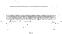
FIG. 2 is a front view of an air conditioner according to an embodiment of the present disclosure; -
FIG. 3 is a side view of an air conditioner according to an embodiment of the present disclosure; -
FIG. 4 is a schematic diagram of an air conditioner according to an embodiment of the present disclosure, in a state that an upper panel is opened; -
FIG. 5 is a schematic diagram of an air conditioner according to an embodiment of the present disclosure, in a state that a breezeless structure covers a first air outlet; -
FIG. 6 is a schematic diagram of an air conditioner according to an embodiment of the present disclosure, in a state that a breezeless structure avoids a first air outlet; -
FIG. 7 is a schematic perspective view of a breezeless structure according to an embodiment of the present disclosure; -
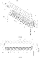
FIG. 8 is an exploded view of a breezeless structure according to an embodiment of the present disclosure; -
FIG. 9 is a front view of a breezeless structure according to an embodiment of the present disclosure; -
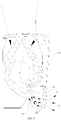
FIG. 10 is a top view of an air dispersing structure according to an embodiment of the present disclosure; and -
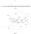
FIG. 11 is a partially enlarged view of a portion A inFIG. 10 . -
- 1000 air conditioner;
- 100 breezeless structure;
- 1 housing; 11 first air outlet; 12 second air outlet; 121 louver; 13 receiving cavity; 14 flow guide plate; 15 air inlet; 16 upper panel;
- 2 movable panel; 21 air dispersing hole; 22 front side plate; 23 bottom plate;
- 3 air dispersing structure; 31 rotating member; 311 rotating blade; 3111 first inner surface;
- 3112 first outer surface; 32 stationary blade assembly; 321 stationary blade; 3211 second inner surface; 3212 second outer surface; 33 mounting plate; 331 ventilation hole; 34 limiting plate; 341 through hole;
- 4 first driving member; 41 transmission gear; 42 first gear; 43 second gear;
- 5 second driving mechanism; 51 motor; 52 gear; and 53 rack.
- Embodiments of the present disclosure are described below in detail, examples of the embodiments are shown in accompanying drawings, and throughout the description, the same or similar reference signs represent the same or similar components or the components having the same or similar functions. The embodiments described below with reference to the accompanying drawings are exemplary and merely used to explain the present disclosure, rather than being construed as limitation on the present disclosure.
- In the description of the present disclosure, it should be understood that the orientation or position relationship indicated by the terms "center", "longitudinal", "transverse", "length", "width", "thickness", "upper", "lower", "front", "rear", "left", "right", "vertical", "horizontal", "top", "bottom", "inner", "outer", "clockwise", "counterclockwise", "axial", "radial", "circumferential", etc., is based on the orientation or position relationship shown in the drawings, and is only for the convenience of describing the present disclosure and simplifying the description, rather than indicating or implying that the defined device or element must have a specific orientation or must be constructed and operated in a specific orientation. Thus, the orientation or position relationship indicated by these terms cannot be understood as limitations of the present disclosure. In addition, the terms "first" and "second" are only used for purpose of description, and cannot be understood as indicating or implying relative importance or implicitly indicating the number of indicated technical features. Therefore, the features defined with "first" and "second" may explicitly or implicitly include at least one of the features. In the description of the present disclosure, "plurality" means at least two, unless otherwise specifically defined.
- In the description of the present disclosure, it should be noted that, unless otherwise clearly specified and limited, terms such as "install", "mount", "connect to" and the like should be understood in a broad sense. For example, it may be a fixed connection or a detachable connection or connection as one piece; mechanical connection or electrical connection; direct connection or indirect connection through an intermediate; internal communication of two components or the interaction relationship between two components, unless otherwise clearly limited. For those of ordinary skill in the art, the specific meaning of the above-mentioned terms in the present disclosure can be understood according to specific circumstances.
- A
breezeless structure 100 of anair conditioner 1000 according to an embodiment of the present disclosure is described with reference toFIG. 1 to FIG. 11 . Theair conditioner 1000 includes ahousing 1, thehousing 1 has anair inlet 15 disposed at an upper end thereof, and external air enters theair conditioner 1000 through theair inlet 15. Thehousing 1 has afirst air outlet 11, thefirst air outlet 11 may be located at a lower end of thehousing 1, and theair conditioner 1000 blows air through thefirst air outlet 11. - According to this embodiment of the present disclosure, the
breezeless structure 100 of theair conditioner 1000 is movably disposed on thehousing 1 to at least partially cover thefirst air outlet 11 or avoid thefirst air outlet 11. It can be understood that, through the movement of thebreezeless structure 100, thefirst air outlet 11 can be entirely opened or closed, or a part of thefirst air outlet 11 can be covered and the covered part of thefirst air outlet 11 may be a part of thefirst air outlet 11 blowing air towards the user or directly blowing air to the user. In this way, the air blown from thefirst air outlet 11 passes through thebreezeless structure 100 before blowing towards the user, so as to disperse the air blowing towards the user, thereby achieving the breezeless effect, and improving the comfortableness of theair conditioner 1000. - The
breezeless structure 100 includes anair dispersing structure 3. Theair dispersing structure 3 includes astationary blade assembly 32 and a rotatingmember 31 that are spaced apart from each other in an air-flowing direction. The rotatingmember 31 is rotatable relative to thestationary blade assembly 32. It can be understood that, in a state that at least part of thefirst air outlet 11 is shielded by thebreezeless structure 100, as thestationary blade assembly 32 and the rotatingmember 31 are spaced apart from each other in the air-flowing direction, the air blown from theair conditioner 1000 can be dispersed by a plurality ofstationary blades 321 for one time and dispersed by the rotatingmember 31 in rotation for one time. Thus, the air blown from theair conditioner 1000 can be dispersed for multiple times and thus can be weakened, so as to improve the comfortableness of theair conditioner 1000. - The
stationary blade assembly 32 includes a plurality ofstationary blades 321 spaced apart from each other in a circumferential direction. The rotatingmember 31 includes a plurality ofrotating blades 311 spaced apart from each other in a circumferential direction. It can be understood that since the rotatingmember 31 is rotatable relative to thestationary blade assembly 32, the positions between the plurality ofrotating blades 311 of the rotatingmember 31 and the plurality ofstationary blades 321 can be adjusted, so as to change an opening degree of a flow channel formed between the rotatingmember 31 and thestationary blade assembly 32, thereby controlling a flow rate of an airflow passing through thebreezeless structure 100 and controlling the air volume of theair conditioner 1000 to satisfy user's demands. - In some embodiments of the present disclosure, the
stationary blade assembly 32 may be disposed at a front side of the rotatingmember 31 in the air-flowing direction. In this way, the air blown from theair conditioner 1000 is firstly dispersed by the plurality ofstationary blades 321, and is subsequently dispersed by the rotatingmember 31, and the air-flowing direction is changed by the rotation of the rotatingmember 31, allowing the air outlet direction of theair conditioner 1000 to be more controllable. - In some embodiments of the present disclosure, the
stationary blade assembly 32 may be disposed at a rear side of the rotatingmember 31 in the air-flowing direction. In this way, the air blown from theair conditioner 1000 is dispersed once by the rotatingmember 31 and subsequently dispersed once by the plurality ofstationary blades 321, so as to sufficiently disperse the air blown from theair conditioner 1000, thereby allowing the air outlet of theair conditioner 1000 to be more comfortable. - In some embodiments of the present disclosure, it may be also possible that only each
rotating blade 311 is obliquely disposed to allow air to flow on opposite side walls of therotating blade 311. In some embodiments of the present disclosure, it may be also possible that only eachstationary blade 321 is obliquely disposed to allow air to flow on opposite side walls of thestationary blade 321. Alternatively, in some embodiments of the present disclosure, not only eachrotating blade 311 is obliquely disposed to allow air to flow on the opposite side walls of therotating blade 311, but also eachstationary blade 321 is obliquely disposed to allow air to flow on the opposite side walls of thestationary blade 321. - When each
rotating blade 311 is obliquely disposed to allow air to flow on the opposite side walls of therotating blade 311, the air blown from theair conditioner 1000 can simultaneously flow on the opposite side walls of therotating blade 311, so as to uniformly heat the opposite side walls of therotating blade 311, thereby avoiding a condensation phenomenon and improving the quality and comfortableness of theair conditioner 1000. - It should be noted that, as illustrated in
FIG. 11 , eachrotating blade 311 has a firstouter surface 3112 and a firstinner surface 3111. The firstouter surface 3112 and the firstinner surface 3111 may be two opposite side walls of therotating blade 311. By obliquely disposing eachrotating blade 311 to change a rotation direction of therotating blades 311, therotating blade 311 extends substantially along the air-flowing direction, thereby avoiding obstruction to the airflow and making the airflow smoother. - Meanwhile, a portion of the air blown from the
air conditioner 1000 contacts the firstouter surface 3112, and a portion thereof contacts the firstinner surface 3111, so as to uniformly heat the opposite side walls of therotating blade 311, thereby avoiding the condensation phenomenon and improving the quality and comfortableness of theair conditioner 1000. - When each
stationary blade 321 is obliquely disposed to allow air to flow on the opposite side walls of thestationary blade 321, the air blown from theair conditioner 1000 simultaneously passes through the opposite side walls of thestationary blade 321, so as to uniformly heat the opposite side walls of thestationary blade 321, thereby avoiding the condensation phenomenon and improving the quality and comfortableness of theair conditioner 1000. - It should be noted that, as shown in
FIG. 11 , eachstationary blade 321 has a secondouter surface 3212 and a secondinner surface 3211. The secondouter surface 3212 and the secondinner surface 3211 may be two opposite side walls of thestationary blade 321. By obliquely disposing eachstationary blade 321 to change a rotation direction of thestationary blade 321, thestationary blade 321 extends substantially along the air-flowing direction, and thus, the obstruction to the airflow is avoided and the airflow is smoother. - Meanwhile, a portion of the air blown from the
air conditioner 1000 contacts the secondouter surface 3212, and a portion thereof contacts the secondinner surface 3211, so as to uniformly heat the opposite side walls of eachstationary blade 321, thereby avoiding the condensation phenomenon and improving the quality and comfortableness of theair conditioner 1000. - In the
breezeless structure 100 of theair conditioner 1000 provided by the embodiment of the present disclosure, the air blown from theair conditioner 1000 is firstly dispersed through theair dispersing structure 3 to achieve the breezeless effect of theair conditioner 1000, thereby improving the comfortableness of theair conditioner 1000. Meanwhile, eachrotating blade 311 is obliquely disposed to allow air to flow on opposite side walls of therotating blade 311, and/or eachstationary blade 321 is obliquely disposed to allow air to flow on opposite side walls of thestationary blade 321. Thus, the opposite side walls of thestationary blade 321 and/or the opposite side walls of therotating blade 311 can be uniformly heated, thereby avoiding the condensation phenomenon and improving the quality and comfortableness of theair conditioner 1000. - In some embodiments of the present disclosure, as shown in
FIG. 11 , eachrotating blade 311 and eachstationary blade 321 are obliquely disposed along the same oblique direction. That is, by obliquely disposing eachrotating blade 311 and eachstationary blade 321, the air blown from theair conditioner 1000 can contact the opposite side walls of therotating blade 311 and the opposite side walls of thestationary blade 321, so as to uniformly heat the opposite side walls of therotating blade 311 and the opposite side walls of thestationary blade 321. Therefore, the condensation phenomenon is prevented from occurring on the rotatingmember 31 and thestationary blade assembly 32, thereby improving the quality and comfortableness of theair conditioner 1000. - Meanwhile, the oblique direction of the
stationary blade 321 is consistent with the oblique direction of therotating blade 311, and thus an extending direction of thestationary blade 321 is approximately the same as an extending direction of therotating blade 311. In this way, the airflow can continuously flow along the side walls of therotating blade 311 after passing through the side walls of thestationary blade 321, to reduce the obstruction to the airflow. In addition, the opposite side walls of eachstationary blade 321 and the opposite side walls of eachrotating blade 311 can be in contact with the air, thereby further solving the problem of condensation on the rotatingmember 31 and thestationary blade assembly 32. - In some embodiments of the present disclosure, each
rotating blade 311 and eachstationary blade 321 are obliquely disposed, and the oblique direction of thestationary blade 321 may not be consistent with the oblique direction of therotating blade 311. As long as the air blown from theair conditioner 1000 can be in contact with and thus uniformly heat the opposite side walls of therotating blade 311 and the opposite side walls of thestationary blade 321, the condensation phenomenon can be prevented from occurring on the rotatingmember 31 and thestationary blade assembly 32, thereby improving the quality and comfortableness of theair conditioner 1000. - In some embodiments of the present disclosure, as shown in
FIG. 7 to FIG. 9 , thebreezeless structure 100 further includes afirst driving member 4. Thefirst driving member 4 is connected to the rotatingmember 31 to drive the rotatingmember 31 to rotate. That is, the rotatingmember 31 is rotated by the first drivingmember 4, allowing the rotation of the rotatingmember 31 to be simpler and more reliable. In some embodiments of the present disclosure, the first drivingmember 4 can be mounted on the mountingplate 33, so that the transmission between the first drivingmember 4 and the rotatingmember 31 is more reliable, and the first drivingmember 4 can be located above the rotatingmember 31 to prevent the first drivingmember 4 from obstructing the airflow, so that the airflow can flow more smoothly. - In some embodiments of the present disclosure, as shown in
FIG. 7 to FIG. 9 , the first drivingmember 4 may be a driving motor, afirst gear 42 is connected to an output shaft of the driving motor, asecond gear 43 is disposed between thefirst gear 42 and the rotatingmember 31, and thesecond gear 43 is engaged with thefirst gear 42 and the rotatingmember 31. In this way, thefirst gear 42 can be driven by the rotating output shaft of the driving motor to rotate, and further thefirst gear 42 can drive the rotatingmember 31 to rotate through thesecond gear 43. At the same time, a rotation speed and a rotation precision of the rotatingmember 31 can be controlled by changing gear ratios of thefirst gear 42, thesecond gear 43, and the rotatingmember 31. - In some embodiments of the present disclosure, a plurality of rotating
members 31 is provided, and every two adjacent rotatingmembers 31 have atransmission gear 41 disposed therebetween and are each engaged with thetransmission gear 41, allowing the plurality of rotatingmembers 31 to rotate synchronously. That is, when the plurality of rotatingmembers 31 is provided, thetransmission gear 41 can be disposed between every two adjacent rotatingmembers 31 in such a manner that the two adjacent rotatingmembers 31 are each engaged with thetransmission gear 41, allowing the plurality of rotatingmembers 31 to rotate synchronously. In this way, it is ensured that rotation angles of therotating members 31 are the same to maintain the same air dispersion effects of therotating members 31, allowing the air blown from theair conditioner 1000 to be more uniform. - In some embodiments of the present disclosure, a plurality of stationary blade assemblies is provided in one-to-one correspondence with the plurality of rotating members. By providing the plurality of rotating
members 31 in one-to-one correspondence with the plurality ofstationary blades 321, the airflow-diffusing function of thebreezeless structure 100 can be intensified, thereby improving the comfortableness of theair conditioner 1000. - In some embodiments of the present disclosure, as shown in
FIG. 1 to FIG. 9 , thebreezeless structure 100 further includes amovable panel 2 movably disposed on thehousing 1. Themovable panel 2 has a plurality ofair dispersing holes 21 disposed thereon. Theair dispersing structure 3 is disposed on a side wall surface of themovable panel 2 facing towards thefirst air outlet 11 and is directly opposite to at least a portion of the plurality of air dispersing holes 21. That is, by moving themovable panel 2 on thehousing 1, themovable panel 2 can at least partially cover or avoid thefirst air outlet 11 . In a state that on thefirst air outlet 11 is covered by themovable panel 2, the air blown from theair conditioner 1000 is first dispersed by theair dispersing structure 3, and then the dispersed air is dispersed through the plurality of air dispersing holes 21 on themovable panel 2 and flows towards an environment where theair conditioner 1000 is located, so as to achieve the breezeless effect of the air blown from theair conditioner 1000, thereby improving the comfortableness of theair conditioner 1000. - In some embodiments of the present disclosure, as shown in
FIG. 3 to FIG. 6 , themovable panel 2 moves in an up-and-down direction, the movable panel covers thefirst air outlet 11 when moving downwards, and the movable panel avoids thefirst air outlet 11 when moving upwards. In this way, the movement of themovable panel 2 is simpler and occupies a smaller moving space. It is understood that themovable panel 2 may be disposed on thehousing 1 to move left and right. - It should be noted that, without changing an air-blowing state by the user, the
movable panel 2 may be moved to make thefirst air outlet 11 in an open state, in which themovable panel 2 avoids thefirst air outlet 11, so that the air blown from theair conditioner 1000 directly blows towards the environment where theair conditioner 1000 is located through thefirst air outlet 11. Further, the air-blowing state of theair conditioner 1000 may be changed based on a selection of the user, allowing the air-blowing of theair conditioner 1000 to be more selectable. Thus, theair conditioner 1000 can meet different requirements of the user. - In some embodiments of the present disclosure, as shown in
FIG. 1 to FIG. 3 , twosecond air outlets 12 are respectively disposed on the left and right sides of thehousing 1, the twosecond air outlets 12 are both in communication with thefirst air outlet 11. In the state that themovable panel 2 covers thefirst air outlet 11, after the air blown from theair conditioner 1000 is dispersed by theair dispersing structure 3, a part of the air is diffused through the plurality of air dispersing holes 21 on themovable panel 2 and flows to the environment where theair conditioner 1000 is located, and the other part of the air is blown to the environment where theair conditioner 1000 through the twosecond air outlets 12 on thehousing 1. In this way, theair conditioner 1000 can blow air from the side and the front of thehousing 1. Therefore, on one hand, an air output amount of theair conditioner 1000 under the breezeless state can be satisfied, on the other hand, the air can be blown from theair conditioner 1000 in various angles, thereby further weakening the air-blowing of theair conditioner 1000, so that the air-blowing of theair conditioner 1000 is more comfortable. - Further, a
louver 121 is rotatably connected inside eachsecond air outlet 12, and a direction of the air blown from thesecond air outlet 12 can be adjusted by rotating thelouver 121. Thus, the direction of the air blown from thesecond air outlet 12 is more controllable and is prevented from blowing towards the user, thereby further improving the comfortableness of theair conditioner 1000. - In some embodiments of the present disclosure, as shown in
FIG. 7 to FIG. 9 , theair dispersing structure 3 includes a mountingplate 33 disposed on themovable panel 2, the mountingplate 33 has aventilation hole 331 disposed thereon, the rotatingmember 31 is mounted on the mountingplate 33 and is directly opposite to theventilation hole 331. That is, the mountingplate 33 is provided with theventilation hole 331 directly opposite to the rotatingmember 31, so that the air blown from theair conditioner 1000 can flow through the mountingplate 33 via theventilation hole 331 to prevent the mountingplate 33 from affecting the flowing of the airflow. In addition, the rotatingmember 31 is mounted on the mountingplate 33, and the mountingplate 33 is connected to themovable panel 2, thereby facilitating the mounting of the rotatingmember 31 and improving the structural strength of themovable panel 2. - In some embodiments of the present disclosure, the plurality of
stationary blades 321 may be disposed in theventilation hole 331 and spaced apart from each other along a circumferential direction of theventilation hole 331. Thus, when the airflow flows through theventilation hole 331, the airflow may be dispersed by the plurality ofstationary blades 321, and thus the structure of thebreezeless structure 100 is simpler. - In some embodiments of the present disclosure, the mounting
plate 33 has a position-limiting protrusion provided thereon. After themovable panel 2 moves to a preset position, the position-limiting protrusion can abut against thehousing 1 to prevent the further movement of themovable panel 2, thereby allowing the movement of themovable panel 2 to be more reliable. - In some embodiments of the present disclosure, as shown in
FIG. 7 to FIG. 9 , themovable panel 2 includes afront side plate 22, and abottom plate 23 connected to a lower end of thefront side plate 22. The plurality of air dispersing holes 21 is defined on thefront side plate 22. When thefirst air outlet 11 is covered by themovable panel 2, thefront side plate 22 is directly opposite to thefirst air outlet 11, thebottom plate 23 is disposed below thefirst air outlet 11, and theair dispersing structure 3 is disposed on thefront side plate 22. That is, theair dispersing structure 3 is disposed on thefront side plate 22, and thefront side plate 22 is directly opposite to thefirst air outlet 11, so that the air blown from theair conditioner 1000 can be dispersed through theair dispersing structure 3, and then the dispersed air is dispersed through the plurality of air dispersing holes 21 on thefront side plate 22 and flows to the environment where theair conditioner 1000 is located. Therefore, the air-still effect of the air-blowing of theair conditioner 1000 can be achieved, and the comfortableness of theair conditioner 1000 can be improved. Meanwhile, by disposing thebottom plate 23, when thebottom plate 23 moves below thefirst air outlet 11, it can be determined that themovable panel 2 is moved in place. - In some embodiments of the present disclosure, the
bottom plate 23 has a plurality ofair dispersing holes 21 disposed thereon. That is, after the air blown from theair conditioner 1000 is dispersed by theair dispersing structure 3, a part of the airflows out from the plurality of air dispersing holes 21 on thefront side plate 22, and the other part of the airflows out from the plurality of air dispersing holes 21 on thebottom plate 23, so that theair conditioner 1000 can be blown out in multiple directions. - In an embodiment of the present disclosure, another part of the airflow may flow out of the
second air outlets 12 on both sides of thehousing 1, so that theair conditioner 1000 can discharge air from the sides, front, and bottom of thehousing 1 at the same time. On a premise that air-blowing amount from multiple directions can be ensured, the air output from various places is also weakened, so that the air output from theair conditioner 1000 is more comfortable. - In some embodiments of the present disclosure, as shown in
FIG. 1 to FIG. 6 , aflow guide plate 14 is rotatably connected to thehousing 1. In the state that themovable panel 2 covers thefirst air outlet 11, theflow guide plate 14 can guide a part of the air dispersed by theair dispersing structure 3 to thebottom plate 23, so that the part of the air can be diffused through the plurality ofair dispersing holes 21 of thebottom plate 23 and flows downward of theair conditioner 1000, thereby preventing the air blown from thefirst air outlet 11 from directly blowing to the user, and improving comfortableness of theair conditioner 1000. - In some embodiments of the present disclosure, as shown in
FIG. 7 to FIG. 9 , thebreezeless structure 100 further includes asecond driving mechanism 5 for driving themovable panel 2 to move. Thesecond driving mechanism 5 includes amotor 51, agear 52, and arack 53. Themotor 51 is disposed on thehousing 1. Thegear 52 is connected to an output shaft of themotor 51. Arack 53 is disposed on theair dispersing structure 3, and therack 53 is adapted to engage with thegear 52. That is, when themovable panel 2 needs to be driven to move, thegear 52 is engaged with therack 53 on theair dispersing structure 3, and themotor 51 rotates forward or backward to drive themovable panel 2 to move upward or downward, allowing the movement of themovable panel 2 to be more reliable. - In some embodiments of the present disclosure, the
second driving mechanisms 5 are disposed on both left and right sides of thebreezeless structure 100, and themovable panel 2 is driven to move up and down by the twosecond driving mechanisms 5 at the same time, allowing the movement of themovable panel 2 to be more reliable. - In some embodiments of the present disclosure, as shown in
FIG. 7 to FIG. 9 , thebreezeless structure 100 further includes a limitingplate 34 disposed on themovable panel 2. During the movement of themovable panel 2, the limitingplate 34 is adapted to contact with thehousing 1 to limit a displacement of themovable panel 2. That is, by means of the limitingplate 34 mounted on themovable panel 2, after themovable panel 2 moves to the preset position, the limitingplate 34 can abut against thehousing 1 to limit the further movement of themovable panel 2, thereby allowing the movement of themovable panel 2 to be more reliable. - In some embodiments of the present disclosure, the limiting
plate 34 has a plurality of throughholes 341 disposed thereon and directly opposite to the plurality of rotatingmembers 31, so that the airflow can pass through the limitingplate 34 via the plurality of throughholes 341, and the limitingplate 34 is prevented from affecting the flow of the airflow. - The
air conditioner 1000 according to an embodiment of the present disclosure includes thehousing 1 and thebreezeless structure 100. Thehousing 1 has thefirst air outlet 11. Thebreezeless structure 100 is that described in the above embodiments of the present disclosure, thebreezeless structure 100 is movably disposed on thehousing 1 to at least partially cover thefirst air outlet 11 or avoid thefirst air outlet 11, and thebreezeless structure 100 is adapted to disperse the air blown from thefirst air outlet 11. - In the
air conditioner 1000 of the embodiment of the present disclosure, the air blown from theair conditioner 1000 is firstly dispersed by theair dispersing structure 3 to achieve the air-still or breezeless effect of the air-blowing of theair conditioner 1000, and thus the comfortableness of theair conditioner 1000 is improved. Meanwhile, eachrotating blade 311 is obliquely disposed to allow air to flow on opposite side walls of therotating blade 311, and/or eachstationary blade 321 is obliquely disposed to allow air to flow on opposite side walls of thestationary blade 321. Thus, the opposite side walls of thestationary blade 321 and/or the opposite side walls of therotating blade 311 can be uniformly heated, thereby avoiding the condensation phenomenon and improving the quality and comfortableness of theair conditioner 1000. - In some embodiments of the present disclosure, as shown in
FIG. 1 to FIG. 6 , thehousing 1 has a receivingcavity 13 disposed therein, and at least a part of thebreezeless structure 100 is accommodated in the receivingcavity 13 in a state that thebreezeless structure 100 avoids thefirst air outlet 11. That is, when thebreezeless structure 100 covers at least a part of thefirst air outlet 11, the remaining part of thebreezeless structure 100 may be accommodated in the receivingcavity 13 to protect thebreezeless structure 100. When thebreezeless structure 100 does not need to cover thefirst air outlet 11, thebreezeless structure 100 may be completely accommodated in the receivingcavity 13 to protect thebreezeless structure 100. - In some embodiments of the present disclosure, as shown in
FIG. 1 to FIG. 6 , the front side of thehousing 1 has anupper panel 16 provided thereon, and the receivingcavity 13 is defined between theupper panel 16 and thehousing 1, thereby simplifying the structure of the receivingcavity 13. Moreover, the portion of theupper panel 16 opposite to thebreezeless structure 100 may be made of a transparent material to observe a position of thebreezeless structure 100. Thus, the position of thebreezeless structure 100 can be more intuitive, so as to facilitate observation and control. - In the specification, descriptions with reference to the terms "an embodiment", "some embodiments", "illustrative embodiments", "an example", "a specific example", "some examples", etc., mean that specific features, structure, materials or characteristics described in conjunction with the embodiment or example are included in at least one embodiment or example of the present disclosure. In this specification, the schematic representations of the above terms do not necessarily refer to the same embodiment or example. Moreover, the described specific features, structures, materials or characteristics may be combined in any one or more embodiments or examples in a suitable manner.
- Although the embodiments of the present disclosure are illustrated and described above, it is conceivable for those skilled in the art that various changes, modifications, replacements, and variations can be made to these embodiments without departing from the principles and spirit of the present disclosure. The scope of the present disclosure shall be defined by the claims as attached and their equivalents.
Claims (10)
- A breezeless structure for an air conditioner, whereinthe air conditioner comprises a housing having a first air outlet, and the breezeless structure is movably disposed on the housing to at least partially cover the first air outlet or avoid the first air outlet,the breezeless structure comprises an air dispersing structure,wherein:the air dispersing structure comprises a stationary blade assembly and a rotating member that are spaced apart from each other in an air-flowing direction; the rotating member is rotatable relative to the stationary blade assembly; the stationary blade assembly comprises a plurality of stationary blades spaced apart from each other in a circumferential direction; the rotating member comprises a plurality of rotating blades spaced apart from each other in the circumferential direction; and each of the plurality of rotating blades is obliquely disposed to allow air to flow on opposite side walls of the rotating blade, and/or each of the plurality of stationary blades is obliquely disposed to allow air to flow on opposite side walls of the stationary blade.
- The breezeless structure of the air conditioner according to claim 1, wherein each of the plurality of rotating blades and each of the plurality of stationary blades are obliquely disposed along a same oblique direction.
- The breezeless structure of the air conditioner according to any one of claims 1 to 2, further comprising a first driving member, wherein the first driving member is connected to the rotating member to drive the rotating member to rotate.
- The breezeless structure of the air conditioner according to claim 3, wherein:the rotating member comprises a plurality of rotating members;a transmission gear is disposed between every two adjacent rotating members of the plurality of rotating members have and is engaged with the every two adjacent rotating members, allowing the plurality of rotating members to rotate synchronously.
- The breezeless structure of the air conditioner according to claim 4, wherein a plurality of stationary blade assemblies is provided in one-to-one correspondence with the plurality of rotating members.
- The breezeless structure of the air conditioner according to any one of claims 1 to 5, further comprising a movable panel movably disposed on the housing,wherein the movable panel has a plurality of air dispersing holes, andwherein the air dispersing structure is disposed on a side wall surface of the movable panel facing towards the first air outlet and is directly opposite to at least a portion of the plurality of air dispersing holes.
- The breezeless structure of the air conditioner according to claim 6, wherein:the air dispersing structure comprises a mounting plate disposed on the movable panel,the mounting plate has a ventilation hole,the rotating member is rotatably connected to the mounting plate and directly opposite to the ventilation hole, andthe stationary blade assembly is disposed in the ventilation hole.
- The breezeless structure of the air conditioner according to claim 6 or 7, wherein:the movable panel comprises a front side plate, and a bottom plate connected to a lower end of the front side plate;the plurality of air dispersing holes is disposed on the front side plate; andwhen the first air outlet is covered by the movable panel, the front side plate is directly opposite to the first air outlet, the bottom plate is disposed below the first air outlet, and the air dispersing structure is disposed on the front side plate.
- The breezeless structure of the air conditioner according to any one of claims 6 to 8, further comprising a limiting plate disposed on the movable panel,
wherein the limiting plate is adapted to, during a movement of the movable panel, be in contact with the housing to limit a displacement of the movable panel. - An air conditioner, comprising;a housing having a first air outlet; andthe breezeless structure according to any one of claims 1 to 9, wherein the breezeless structure is movably disposed on the housing to at least partially cover the first air outlet or avoid the first air outlet, and the breezeless structure is adapted to disperse air blown from the first air outlet.
Applications Claiming Priority (3)
| Application Number | Priority Date | Filing Date | Title |
|---|---|---|---|
| CN201911108261.4A CN110701771B (en) | 2019-11-13 | 2019-11-13 | Air conditioner wind-free structure and air conditioner having the same |
| CN201921961268.6U CN210861622U (en) | 2019-11-13 | 2019-11-13 | Windless structure of air conditioner and air conditioner having the same |
| PCT/CN2020/127808 WO2021093729A1 (en) | 2019-11-13 | 2020-11-10 | Indirect airflow structure for air conditioner and air conditioner having same |
Publications (4)
| Publication Number | Publication Date |
|---|---|
| EP4056917A1 true EP4056917A1 (en) | 2022-09-14 |
| EP4056917A4 EP4056917A4 (en) | 2022-12-28 |
| EP4056917C0 EP4056917C0 (en) | 2024-03-06 |
| EP4056917B1 EP4056917B1 (en) | 2024-03-06 |
Family
ID=75911790
Family Applications (1)
| Application Number | Title | Priority Date | Filing Date |
|---|---|---|---|
| EP20887213.5A Active EP4056917B1 (en) | 2019-11-13 | 2020-11-10 | Indirect airflow structure for air conditioner and air conditioner having same |
Country Status (3)
| Country | Link |
|---|---|
| US (1) | US12169073B2 (en) |
| EP (1) | EP4056917B1 (en) |
| WO (1) | WO2021093729A1 (en) |
Families Citing this family (1)
| Publication number | Priority date | Publication date | Assignee | Title |
|---|---|---|---|---|
| CN116989464A (en) * | 2022-04-25 | 2023-11-03 | 广东美的制冷设备有限公司 | air conditioner |
Family Cites Families (19)
| Publication number | Priority date | Publication date | Assignee | Title |
|---|---|---|---|---|
| JP2003184797A (en) * | 2001-12-14 | 2003-07-03 | Daikin Ind Ltd | Blower and air conditioner provided with the blower |
| JP2008038820A (en) * | 2006-08-09 | 2008-02-21 | Denso Corp | Blower for vehicle |
| JP5457128B2 (en) * | 2009-10-05 | 2014-04-02 | 新晃工業株式会社 | Air conditioner with two air supply fans |
| JP2017053295A (en) * | 2015-09-11 | 2017-03-16 | 三星電子株式会社Samsung Electronics Co.,Ltd. | Air blower and outdoor device |
| CN105509284A (en) * | 2015-12-18 | 2016-04-20 | 广东美的制冷设备有限公司 | Air deflector assembly for air conditioner and air conditioner |
| CN205351503U (en) * | 2015-12-18 | 2016-06-29 | 广东美的制冷设备有限公司 | Air -conditioner |
| CN105509285A (en) * | 2015-12-18 | 2016-04-20 | 广东美的制冷设备有限公司 | Air guide plate component for air conditioner and air conditioner |
| CN207073927U (en) * | 2017-07-25 | 2018-03-06 | 广东美的制冷设备有限公司 | Wind deflector and there is its air conditioner |
| CN207146602U (en) * | 2017-08-21 | 2018-03-27 | 广东美的制冷设备有限公司 | Air conditioner room unit and air conditioner |
| CN107588528A (en) * | 2017-09-30 | 2018-01-16 | 广东美的制冷设备有限公司 | Deep bead and indoor apparatus of air conditioner |
| CN107655188A (en) * | 2017-10-02 | 2018-02-02 | 广东美的制冷设备有限公司 | Indoor apparatus of air conditioner |
| CN107702216B (en) * | 2017-10-02 | 2024-10-15 | 广东美的制冷设备有限公司 | Wall-mounted indoor unit and air conditioner |
| CN207555772U (en) * | 2017-11-30 | 2018-06-29 | 广东美的制冷设备有限公司 | Wall-hanging air conditioner indoor unit and with its air conditioner |
| CN110319569A (en) * | 2019-08-09 | 2019-10-11 | 广东美的制冷设备有限公司 | Air conditioner |
| CN110319565A (en) * | 2019-08-09 | 2019-10-11 | 广东美的制冷设备有限公司 | Air conditioner, the control method of air conditioner and storage medium |
| CN110701772B (en) * | 2019-11-13 | 2025-09-23 | 广东美的制冷设备有限公司 | Air conditioner wind-free structure and air conditioner having the same |
| CN210861622U (en) * | 2019-11-13 | 2020-06-26 | 广东美的制冷设备有限公司 | Windless structure of air conditioner and air conditioner having the same |
| CN110701771B (en) * | 2019-11-13 | 2025-09-23 | 广东美的制冷设备有限公司 | Air conditioner wind-free structure and air conditioner having the same |
| CN210861621U (en) * | 2019-11-13 | 2020-06-26 | 广东美的制冷设备有限公司 | Non-wind-sensing structure of air conditioner and air conditioner with same |
-
2020
- 2020-11-10 WO PCT/CN2020/127808 patent/WO2021093729A1/en not_active Ceased
- 2020-11-10 EP EP20887213.5A patent/EP4056917B1/en active Active
-
2022
- 2022-05-10 US US17/740,803 patent/US12169073B2/en active Active
Also Published As
| Publication number | Publication date |
|---|---|
| EP4056917A4 (en) | 2022-12-28 |
| WO2021093729A1 (en) | 2021-05-20 |
| EP4056917C0 (en) | 2024-03-06 |
| US20220268452A1 (en) | 2022-08-25 |
| EP4056917B1 (en) | 2024-03-06 |
| US12169073B2 (en) | 2024-12-17 |
Similar Documents
| Publication | Publication Date | Title |
|---|---|---|
| CN110701772B (en) | Air conditioner wind-free structure and air conditioner having the same | |
| CN110701771B (en) | Air conditioner wind-free structure and air conditioner having the same | |
| CN109520019B (en) | Air conditioner indoor unit and air conditioner having the same | |
| KR20040007323A (en) | Air conditioner | |
| CN210861622U (en) | Windless structure of air conditioner and air conditioner having the same | |
| CN102162674B (en) | Sliding door device | |
| CN110440432B (en) | Air Conditioner | |
| CN112797482A (en) | Indoor unit of air conditioner | |
| US12339030B2 (en) | Air outlet device and air conditioning apparatus | |
| CN110701770A (en) | Air guide assembly, windless structure of air conditioner, and air conditioner | |
| CN111140922A (en) | Air conditioner indoor unit and air conditioner | |
| US12169073B2 (en) | Breezeless structure for air conditioner and air conditioner having the same | |
| CN210861621U (en) | Non-wind-sensing structure of air conditioner and air conditioner with same | |
| CN112880172B (en) | Control method of air conditioner | |
| CN211575272U (en) | Air conditioner indoor unit and air conditioner having the same | |
| CN210345818U (en) | Air conditioner | |
| CN211575268U (en) | Indoor air conditioner on-hook | |
| CN215675459U (en) | Air conditioner indoor unit | |
| CN215675467U (en) | Indoor unit of air conditioner | |
| CN111237867B (en) | Control method of air conditioner and air conditioner | |
| CN209944515U (en) | Indoor unit of air conditioner | |
| CN213514112U (en) | Air conditioner cabinet | |
| CN222783686U (en) | Air guide plate assembly and air conditioner | |
| CN222210534U (en) | Indoor unit of air conditioner and air conditioner | |
| CN223484459U (en) | Air conditioner |
Legal Events
| Date | Code | Title | Description |
|---|---|---|---|
| STAA | Information on the status of an ep patent application or granted ep patent |
Free format text: STATUS: THE INTERNATIONAL PUBLICATION HAS BEEN MADE |
|
| PUAI | Public reference made under article 153(3) epc to a published international application that has entered the european phase |
Free format text: ORIGINAL CODE: 0009012 |
|
| STAA | Information on the status of an ep patent application or granted ep patent |
Free format text: STATUS: REQUEST FOR EXAMINATION WAS MADE |
|
| 17P | Request for examination filed |
Effective date: 20220609 |
|
| AK | Designated contracting states |
Kind code of ref document: A1 Designated state(s): AL AT BE BG CH CY CZ DE DK EE ES FI FR GB GR HR HU IE IS IT LI LT LU LV MC MK MT NL NO PL PT RO RS SE SI SK SM TR |
|
| RAP3 | Party data changed (applicant data changed or rights of an application transferred) |
Owner name: MIDEA GROUP CO., LTD. Owner name: GD MIDEA AIR-CONDITIONING EQUIPMENT CO., LTD. |
|
| A4 | Supplementary search report drawn up and despatched |
Effective date: 20221124 |
|
| RIC1 | Information provided on ipc code assigned before grant |
Ipc: F24F 1/0011 20190101ALI20221118BHEP Ipc: F24F 13/20 20060101ALI20221118BHEP Ipc: F24F 13/08 20060101ALI20221118BHEP Ipc: F24F 1/0033 20190101ALI20221118BHEP Ipc: F24F 1/0014 20190101ALI20221118BHEP Ipc: F24F 13/15 20060101ALI20221118BHEP Ipc: F24F 13/14 20060101AFI20221118BHEP |
|
| DAV | Request for validation of the european patent (deleted) | ||
| DAX | Request for extension of the european patent (deleted) | ||
| GRAP | Despatch of communication of intention to grant a patent |
Free format text: ORIGINAL CODE: EPIDOSNIGR1 |
|
| STAA | Information on the status of an ep patent application or granted ep patent |
Free format text: STATUS: GRANT OF PATENT IS INTENDED |
|
| INTG | Intention to grant announced |
Effective date: 20231027 |
|
| GRAS | Grant fee paid |
Free format text: ORIGINAL CODE: EPIDOSNIGR3 |
|
| GRAA | (expected) grant |
Free format text: ORIGINAL CODE: 0009210 |
|
| STAA | Information on the status of an ep patent application or granted ep patent |
Free format text: STATUS: THE PATENT HAS BEEN GRANTED |
|
| AK | Designated contracting states |
Kind code of ref document: B1 Designated state(s): AL AT BE BG CH CY CZ DE DK EE ES FI FR GB GR HR HU IE IS IT LI LT LU LV MC MK MT NL NO PL PT RO RS SE SI SK SM TR |
|
| REG | Reference to a national code |
Ref country code: CH Ref legal event code: EP |
|
| REG | Reference to a national code |
Ref country code: DE Ref legal event code: R096 Ref document number: 602020027003 Country of ref document: DE |
|
| REG | Reference to a national code |
Ref country code: IE Ref legal event code: FG4D |
|
| U01 | Request for unitary effect filed |
Effective date: 20240318 |
|
| U07 | Unitary effect registered |
Designated state(s): AT BE BG DE DK EE FI FR IT LT LU LV MT NL PT SE SI Effective date: 20240326 |
|
| PG25 | Lapsed in a contracting state [announced via postgrant information from national office to epo] |
Ref country code: GR Free format text: LAPSE BECAUSE OF FAILURE TO SUBMIT A TRANSLATION OF THE DESCRIPTION OR TO PAY THE FEE WITHIN THE PRESCRIBED TIME-LIMIT Effective date: 20240607 |
|
| PG25 | Lapsed in a contracting state [announced via postgrant information from national office to epo] |
Ref country code: RS Free format text: LAPSE BECAUSE OF FAILURE TO SUBMIT A TRANSLATION OF THE DESCRIPTION OR TO PAY THE FEE WITHIN THE PRESCRIBED TIME-LIMIT Effective date: 20240606 Ref country code: HR Free format text: LAPSE BECAUSE OF FAILURE TO SUBMIT A TRANSLATION OF THE DESCRIPTION OR TO PAY THE FEE WITHIN THE PRESCRIBED TIME-LIMIT Effective date: 20240306 |
|
| PG25 | Lapsed in a contracting state [announced via postgrant information from national office to epo] |
Ref country code: ES Free format text: LAPSE BECAUSE OF FAILURE TO SUBMIT A TRANSLATION OF THE DESCRIPTION OR TO PAY THE FEE WITHIN THE PRESCRIBED TIME-LIMIT Effective date: 20240306 |
|
| PG25 | Lapsed in a contracting state [announced via postgrant information from national office to epo] |
Ref country code: RS Free format text: LAPSE BECAUSE OF FAILURE TO SUBMIT A TRANSLATION OF THE DESCRIPTION OR TO PAY THE FEE WITHIN THE PRESCRIBED TIME-LIMIT Effective date: 20240606 Ref country code: NO Free format text: LAPSE BECAUSE OF FAILURE TO SUBMIT A TRANSLATION OF THE DESCRIPTION OR TO PAY THE FEE WITHIN THE PRESCRIBED TIME-LIMIT Effective date: 20240606 Ref country code: HR Free format text: LAPSE BECAUSE OF FAILURE TO SUBMIT A TRANSLATION OF THE DESCRIPTION OR TO PAY THE FEE WITHIN THE PRESCRIBED TIME-LIMIT Effective date: 20240306 Ref country code: GR Free format text: LAPSE BECAUSE OF FAILURE TO SUBMIT A TRANSLATION OF THE DESCRIPTION OR TO PAY THE FEE WITHIN THE PRESCRIBED TIME-LIMIT Effective date: 20240607 Ref country code: ES Free format text: LAPSE BECAUSE OF FAILURE TO SUBMIT A TRANSLATION OF THE DESCRIPTION OR TO PAY THE FEE WITHIN THE PRESCRIBED TIME-LIMIT Effective date: 20240306 |
|
| PG25 | Lapsed in a contracting state [announced via postgrant information from national office to epo] |
Ref country code: IS Free format text: LAPSE BECAUSE OF FAILURE TO SUBMIT A TRANSLATION OF THE DESCRIPTION OR TO PAY THE FEE WITHIN THE PRESCRIBED TIME-LIMIT Effective date: 20240706 |
|
| PG25 | Lapsed in a contracting state [announced via postgrant information from national office to epo] |
Ref country code: SM Free format text: LAPSE BECAUSE OF FAILURE TO SUBMIT A TRANSLATION OF THE DESCRIPTION OR TO PAY THE FEE WITHIN THE PRESCRIBED TIME-LIMIT Effective date: 20240306 |
|
| PG25 | Lapsed in a contracting state [announced via postgrant information from national office to epo] |
Ref country code: CZ Free format text: LAPSE BECAUSE OF FAILURE TO SUBMIT A TRANSLATION OF THE DESCRIPTION OR TO PAY THE FEE WITHIN THE PRESCRIBED TIME-LIMIT Effective date: 20240306 |
|
| PG25 | Lapsed in a contracting state [announced via postgrant information from national office to epo] |
Ref country code: PL Free format text: LAPSE BECAUSE OF FAILURE TO SUBMIT A TRANSLATION OF THE DESCRIPTION OR TO PAY THE FEE WITHIN THE PRESCRIBED TIME-LIMIT Effective date: 20240306 |
|
| PG25 | Lapsed in a contracting state [announced via postgrant information from national office to epo] |
Ref country code: SK Free format text: LAPSE BECAUSE OF FAILURE TO SUBMIT A TRANSLATION OF THE DESCRIPTION OR TO PAY THE FEE WITHIN THE PRESCRIBED TIME-LIMIT Effective date: 20240306 |
|
| PG25 | Lapsed in a contracting state [announced via postgrant information from national office to epo] |
Ref country code: SM Free format text: LAPSE BECAUSE OF FAILURE TO SUBMIT A TRANSLATION OF THE DESCRIPTION OR TO PAY THE FEE WITHIN THE PRESCRIBED TIME-LIMIT Effective date: 20240306 Ref country code: SK Free format text: LAPSE BECAUSE OF FAILURE TO SUBMIT A TRANSLATION OF THE DESCRIPTION OR TO PAY THE FEE WITHIN THE PRESCRIBED TIME-LIMIT Effective date: 20240306 Ref country code: RO Free format text: LAPSE BECAUSE OF FAILURE TO SUBMIT A TRANSLATION OF THE DESCRIPTION OR TO PAY THE FEE WITHIN THE PRESCRIBED TIME-LIMIT Effective date: 20240306 Ref country code: PL Free format text: LAPSE BECAUSE OF FAILURE TO SUBMIT A TRANSLATION OF THE DESCRIPTION OR TO PAY THE FEE WITHIN THE PRESCRIBED TIME-LIMIT Effective date: 20240306 Ref country code: IS Free format text: LAPSE BECAUSE OF FAILURE TO SUBMIT A TRANSLATION OF THE DESCRIPTION OR TO PAY THE FEE WITHIN THE PRESCRIBED TIME-LIMIT Effective date: 20240706 Ref country code: CZ Free format text: LAPSE BECAUSE OF FAILURE TO SUBMIT A TRANSLATION OF THE DESCRIPTION OR TO PAY THE FEE WITHIN THE PRESCRIBED TIME-LIMIT Effective date: 20240306 |
|
| REG | Reference to a national code |
Ref country code: DE Ref legal event code: R097 Ref document number: 602020027003 Country of ref document: DE |
|
| U20 | Renewal fee for the european patent with unitary effect paid |
Year of fee payment: 5 Effective date: 20241122 |
|
| PLBE | No opposition filed within time limit |
Free format text: ORIGINAL CODE: 0009261 |
|
| STAA | Information on the status of an ep patent application or granted ep patent |
Free format text: STATUS: NO OPPOSITION FILED WITHIN TIME LIMIT |
|
| 26N | No opposition filed |
Effective date: 20241209 |
|
| REG | Reference to a national code |
Ref country code: CH Ref legal event code: PL |
|
| PG25 | Lapsed in a contracting state [announced via postgrant information from national office to epo] |
Ref country code: MC Free format text: LAPSE BECAUSE OF FAILURE TO SUBMIT A TRANSLATION OF THE DESCRIPTION OR TO PAY THE FEE WITHIN THE PRESCRIBED TIME-LIMIT Effective date: 20240306 |
|
| REG | Reference to a national code |
Ref country code: CH Ref legal event code: PL |
|
| GBPC | Gb: european patent ceased through non-payment of renewal fee |
Effective date: 20241110 |
|
| PG25 | Lapsed in a contracting state [announced via postgrant information from national office to epo] |
Ref country code: CH Free format text: LAPSE BECAUSE OF NON-PAYMENT OF DUE FEES Effective date: 20241130 |
|
| PG25 | Lapsed in a contracting state [announced via postgrant information from national office to epo] |
Ref country code: GB Free format text: LAPSE BECAUSE OF NON-PAYMENT OF DUE FEES Effective date: 20241110 |
|
| PG25 | Lapsed in a contracting state [announced via postgrant information from national office to epo] |
Ref country code: IE Free format text: LAPSE BECAUSE OF NON-PAYMENT OF DUE FEES Effective date: 20241110 |
|
| U20 | Renewal fee for the european patent with unitary effect paid |
Year of fee payment: 6 Effective date: 20251127 |
|
| PG25 | Lapsed in a contracting state [announced via postgrant information from national office to epo] |
Ref country code: HU Free format text: LAPSE BECAUSE OF FAILURE TO SUBMIT A TRANSLATION OF THE DESCRIPTION OR TO PAY THE FEE WITHIN THE PRESCRIBED TIME-LIMIT; INVALID AB INITIO Effective date: 20201110 |
|
| PG25 | Lapsed in a contracting state [announced via postgrant information from national office to epo] |
Ref country code: CY Free format text: LAPSE BECAUSE OF FAILURE TO SUBMIT A TRANSLATION OF THE DESCRIPTION OR TO PAY THE FEE WITHIN THE PRESCRIBED TIME-LIMIT; INVALID AB INITIO Effective date: 20201110 |
|
| U1N | Appointed representative for the unitary patent procedure changed after the registration of the unitary effect |
Representative=s name: TREEBY, PHILIP DAVID WILLIAM; GB |