EP4056860A1 - Explosion-proof structure - Google Patents
Explosion-proof structure Download PDFInfo
- Publication number
- EP4056860A1 EP4056860A1 EP22158845.2A EP22158845A EP4056860A1 EP 4056860 A1 EP4056860 A1 EP 4056860A1 EP 22158845 A EP22158845 A EP 22158845A EP 4056860 A1 EP4056860 A1 EP 4056860A1
- Authority
- EP
- European Patent Office
- Prior art keywords
- explosion
- proof structure
- fastener
- hole
- internal space
- Prior art date
- Legal status (The legal status is an assumption and is not a legal conclusion. Google has not performed a legal analysis and makes no representation as to the accuracy of the status listed.)
- Granted
Links
Images


Classifications
-
- F—MECHANICAL ENGINEERING; LIGHTING; HEATING; WEAPONS; BLASTING
- F16—ENGINEERING ELEMENTS AND UNITS; GENERAL MEASURES FOR PRODUCING AND MAINTAINING EFFECTIVE FUNCTIONING OF MACHINES OR INSTALLATIONS; THERMAL INSULATION IN GENERAL
- F16B—DEVICES FOR FASTENING OR SECURING CONSTRUCTIONAL ELEMENTS OR MACHINE PARTS TOGETHER, e.g. NAILS, BOLTS, CIRCLIPS, CLAMPS, CLIPS OR WEDGES; JOINTS OR JOINTING
- F16B5/00—Joining sheets or plates, e.g. panels, to one another or to strips or bars parallel to them
- F16B5/02—Joining sheets or plates, e.g. panels, to one another or to strips or bars parallel to them by means of fastening members using screw-thread
-
- B—PERFORMING OPERATIONS; TRANSPORTING
- B65—CONVEYING; PACKING; STORING; HANDLING THIN OR FILAMENTARY MATERIAL
- B65D—CONTAINERS FOR STORAGE OR TRANSPORT OF ARTICLES OR MATERIALS, e.g. BAGS, BARRELS, BOTTLES, BOXES, CANS, CARTONS, CRATES, DRUMS, JARS, TANKS, HOPPERS, FORWARDING CONTAINERS; ACCESSORIES, CLOSURES, OR FITTINGS THEREFOR; PACKAGING ELEMENTS; PACKAGES
- B65D77/00—Packages formed by enclosing articles or materials in preformed containers, e.g. boxes, cartons, sacks or bags
- B65D77/22—Details
- B65D77/225—Pressure relief-valves incorporated in a container wall, e.g. valves comprising at least one elastic element
-
- H—ELECTRICITY
- H05—ELECTRIC TECHNIQUES NOT OTHERWISE PROVIDED FOR
- H05K—PRINTED CIRCUITS; CASINGS OR CONSTRUCTIONAL DETAILS OF ELECTRIC APPARATUS; MANUFACTURE OF ASSEMBLAGES OF ELECTRICAL COMPONENTS
- H05K5/00—Casings, cabinets or drawers for electric apparatus
- H05K5/06—Hermetically-sealed casings
- H05K5/061—Hermetically-sealed casings sealed by a gasket held between a removable cover and a body, e.g. O-ring, packing
-
- H—ELECTRICITY
- H05—ELECTRIC TECHNIQUES NOT OTHERWISE PROVIDED FOR
- H05K—PRINTED CIRCUITS; CASINGS OR CONSTRUCTIONAL DETAILS OF ELECTRIC APPARATUS; MANUFACTURE OF ASSEMBLAGES OF ELECTRICAL COMPONENTS
- H05K5/00—Casings, cabinets or drawers for electric apparatus
- H05K5/10—Casings, cabinets or drawers for electric apparatus comprising several parts forming a closed casing
- H05K5/13—Casings, cabinets or drawers for electric apparatus comprising several parts forming a closed casing assembled by screws
-
- H—ELECTRICITY
- H05—ELECTRIC TECHNIQUES NOT OTHERWISE PROVIDED FOR
- H05K—PRINTED CIRCUITS; CASINGS OR CONSTRUCTIONAL DETAILS OF ELECTRIC APPARATUS; MANUFACTURE OF ASSEMBLAGES OF ELECTRICAL COMPONENTS
- H05K7/00—Constructional details common to different types of electric apparatus
- H05K7/14—Mounting supporting structure in casing or on frame or rack
-
- F—MECHANICAL ENGINEERING; LIGHTING; HEATING; WEAPONS; BLASTING
- F16—ENGINEERING ELEMENTS AND UNITS; GENERAL MEASURES FOR PRODUCING AND MAINTAINING EFFECTIVE FUNCTIONING OF MACHINES OR INSTALLATIONS; THERMAL INSULATION IN GENERAL
- F16B—DEVICES FOR FASTENING OR SECURING CONSTRUCTIONAL ELEMENTS OR MACHINE PARTS TOGETHER, e.g. NAILS, BOLTS, CIRCLIPS, CLAMPS, CLIPS OR WEDGES; JOINTS OR JOINTING
- F16B33/00—Features common to bolt and nut
- F16B33/004—Sealing; Insulation
-
- F—MECHANICAL ENGINEERING; LIGHTING; HEATING; WEAPONS; BLASTING
- F16—ENGINEERING ELEMENTS AND UNITS; GENERAL MEASURES FOR PRODUCING AND MAINTAINING EFFECTIVE FUNCTIONING OF MACHINES OR INSTALLATIONS; THERMAL INSULATION IN GENERAL
- F16B—DEVICES FOR FASTENING OR SECURING CONSTRUCTIONAL ELEMENTS OR MACHINE PARTS TOGETHER, e.g. NAILS, BOLTS, CIRCLIPS, CLAMPS, CLIPS OR WEDGES; JOINTS OR JOINTING
- F16B37/00—Nuts or like thread-engaging members
- F16B37/14—Cap nuts; Nut caps or bolt caps
-
- Y—GENERAL TAGGING OF NEW TECHNOLOGICAL DEVELOPMENTS; GENERAL TAGGING OF CROSS-SECTIONAL TECHNOLOGIES SPANNING OVER SEVERAL SECTIONS OF THE IPC; TECHNICAL SUBJECTS COVERED BY FORMER USPC CROSS-REFERENCE ART COLLECTIONS [XRACs] AND DIGESTS
- Y02—TECHNOLOGIES OR APPLICATIONS FOR MITIGATION OR ADAPTATION AGAINST CLIMATE CHANGE
- Y02E—REDUCTION OF GREENHOUSE GAS [GHG] EMISSIONS, RELATED TO ENERGY GENERATION, TRANSMISSION OR DISTRIBUTION
- Y02E60/00—Enabling technologies; Technologies with a potential or indirect contribution to GHG emissions mitigation
- Y02E60/10—Energy storage using batteries
Definitions
- the present disclosure relates to an explosion-proof structure.
- Patent Literature (PTL) 1 An explosion-proof structure formed by a fastener and two internal space-forming members, which are joined together to form an internal space by the fastener being inserted into an insertion hole and fastened to a fastening hole, is known. For example, see Patent Literature (PTL) 1.
- the above-described explosion-proof structure is difficult to reduce in size, for example since flanges with insertion holes and fastening holes may need to be provided.
- An explosion-proof structure is formed by a fastener, two internal space-forming members joined together to form an internal space by the fastener being inserted into an insertion hole and fastened to a fastening hole, and a plug attached to the insertion hole so as to cover a head of the fastener.
- the plug in the explosion-proof structure includes a recess to accommodate the head. According to this configuration, the depth of the insertion hole can be reduced, making it even easier to achieve a reduction in size of the explosion-proof structure.
- the plug in the explosion-proof structure includes a male thread that screws into the insertion hole. According to this configuration, the degree of freedom in the arrangement of fasteners can be further increased, making it even easier to achieve a reduction in size of the explosion-proof structure.
- the fastener in the explosion-proof structure is configured as a bolt. According to this configuration, fastening can be achieved with a simple structure.
- the fastening hole in the explosion-proof structure is configured as a screw hole. According to this configuration, fastening can be achieved with a simple structure.
- the explosion-proof structure 1 is formed by two internal space-forming members 2 and one or more (six in the present embodiment) pairs of a fastener 3 and a plug 4.
- the two internal space-forming members 2 include one or more (six in the present embodiment) pairs of an insertion hole 5 and a fastening hole 6, corresponding in number to the fasteners 3 and plugs 4.
- the explosion-proof structure 1 includes one or more (six in the present embodiment) fastening portions 7, each formed by a fastener 3, a plug 4, an insertion hole 5, and a fastening hole 6. All of the fastening portions 7 have the same structure and orientation.
- the two internal space-forming members 2, the fasteners 3, and the plugs 4 are each made of metal, for example.
- the explosion-proof structure 1 is the structure of an explosion-proof container for a converter that forms a sensor device as a field device used in a plant.
- the explosion-proof structure 1 may, however, be the structure of a container for field devices other than such a converter.
- Field devices refer to sensor devices such as pressure gauges, flow meters, and temperature sensors; valve devices, such as flow control valves and opening/closing valves; actuator devices, such as fans or motors; image capturing devices, such as cameras and video recorders, that capture images of the conditions and objects in the plant; acoustic devices, such as microphones that collect abnormal noises and the like inside the plant and speakers that emit warning sounds or the like; position detectors that output positional information for various devices; and other such devices.
- the plant is an industrial plant such as a chemical plant; a plant for managing a well site, such as a gas field or oil field, and the surrounding area; a plant for managing power generation such as hydroelectric power, thermal power, nuclear power, or the like; a plant for managing environmental power generation such as solar power, wind power, or the like; a plant for managing water and sewage, a dam, or the like; or another type of plant.
- a chemical plant such as a chemical plant
- a plant for managing a well site such as a gas field or oil field, and the surrounding area
- a plant for managing power generation such as hydroelectric power, thermal power, nuclear power, or the like
- a plant for managing environmental power generation such as solar power, wind power, or the like
- a plant for managing water and sewage, a dam, or the like or another type of plant.
- the two internal space-forming members 2 are joined together to form an internal space 10 by each fastener 3 being inserted into an insertion hole 5, provided in correspondence with the fastener 3 in one internal space-forming member 2 (hereinafter also referred to as a first member 8), and fastened to a fastening hole 6, provided in correspondence with the fastener 3 in the other internal space-forming member 2 (hereinafter also referred to as a second member 9).
- the first member 8 is a lid
- the second member 9 is a housing, but this example is not limiting.
- the first member 8 may be a housing
- the second member 9 may be a lid.
- the fastener 3 includes a shaft 3a that is fastened to the fastening hole 6 and a head 3b that is larger in diameter than the shaft 3a.
- the head 3b includes an operable part (hereinafter referred to as a first operable part 3c), configured by a non-circular hole formed on the upper surface, to receive a rotational operation for fastening.
- the fastener 3 is configured as a bolt, with the shaft 3a being a threaded shaft, and the fastening hole 6 is configured as a threaded hole.
- the up-down direction refers to the direction along the central axis O of the shaft 3a of the fastener 3 (e.g., the up-down direction in FIG. 2 )
- the radial direction refers to the direction along a straight line orthogonal to the central axis O
- the circumferential direction refers to the direction around the central axis O.
- the plug 4 is attached to the insertion hole 5 so as to cover the head 3b of the fastener 3.
- the plug 4 includes a plug body 4a that covers the head 3b of the fastener 3 and an eave 4b that protrudes radially outward from the upper end of the plug body 4a and extends annularly in the circumferential direction.
- the portion of the outer circumferential surface of the plug body 4a other than the upper end includes a male thread 4c.
- the upper end of the outer circumferential surface of the plug body 4a includes a circumferential groove 4d extending annularly in the circumferential direction.
- An annular elastic sealing member (hereinafter referred to as a first sealing member 11) is provided across the entire circumference of the circumferential groove 4d.
- the lower surface of the plug body 4a includes a recess 4e to accommodate the head 3b.
- the upper surface of the plug body 4a includes an operable part (hereinafter referred to as a second operable part 4f), configured by a non-circular hole, to receive a rotational operation for fastening.
- the second operable part 4f has the same structure as the first operable part 3c.
- the insertion hole 5 is a through-hole.
- the insertion hole 5 includes a first hole 5a that has an inner diameter smaller than the outer diameter of the head 3b and equal to or greater than the outer diameter of the shaft 3a, a second hole 5b that is connected to the upper end of the first hole 5a and has an inner diameter larger than the outer diameter of the head 3b, and a third hole 5c that is connected to the upper end of the second hole 5b and has an inner diameter equal to or greater than the outer diameter of the eave 4b.
- the inner circumferential surface of the first hole 5a is a flat cylindrical surface.
- the bottom surface of the second hole 5b abuts against the bottom surface of the head 3b.
- At least a portion of the inner circumferential surface of the second hole 5b other than the upper end includes a female thread 5d into which the male thread 4c is screwed.
- the upper end of the inner circumferential surface of the second hole 5b is in close contact with the sealing member across the entire circumference thereof.
- the bottom surface of the third hole 5c abuts against the bottom surface of the eave 4b.
- the two internal space-forming members 2 include two joints 12 that are joined together by each fastener 3 being inserted into the insertion hole 5 corresponding to the fastener 3 and fastened to the fastening hole 6 corresponding to the fastener 3, and that form a ring extending along the outer periphery of the internal space 10.
- One of the joints 12 includes a recessed groove 13, on the joint surface, that forms a ring extending along the outer periphery of the internal space 10.
- An annular elastic sealing member (hereinafter referred to as a second sealing member 14) is provided across the entire circumference of the recessed groove 13.
- the second sealing member 14 is not illustrated in FIG. 1 , but only in FIG. 2 .
- the second sealing member 14 is in close contact with the other joint 12 across the entire circumference thereof.
- the second member 9 includes the recessed groove 13 in the present embodiment, this example is not limiting, and the first member 8 may be configured to include the recessed groove 13.
- the first sealing member 11 and the second sealing member 14 can each be provided for waterproofing, dustproofing, or the like. As long as explosion-proof performance can be ensured, a configuration without the first sealing member 11 (and peripheral groove 4d) and the second sealing member 14 (and recessed groove 13) may be adopted.
- the second member 9 includes the fastening holes 6 on the internal space 10 side of the annular joint 12.
- the fastening portions 7 are located on the internal space 10 side of the two joints 12.
- the insertion holes 5 communicate with the internal space 10.
- the degree of freedom in arranging one or more fastening portions 7 can be increased.
- the fastening portions 7 can be arranged on the internal space 10 side of the two joints 12, as in the present embodiment. This makes it easier to achieve a reduction in size of the explosion-proof structure 1. Furthermore, a reduction in size of the explosion-proof structure 1 reduces the number of fastening portions 7, thereby facilitating a reduction in cost.
- the plug 4 since the plug 4 includes a recess 4e that accommodates the head 3b, the depth of the insertion hole 5 can be reduced and the thickness of the fastening portion 7 in the up-down direction can be reduced.
- the first member 8 is a lid and the second member 9 is a housing.
- the first member 8 may be a window for maintenance work
- the second member 9 may be a lid, as in the second embodiment illustrated in FIGS. 4 to 5 .
- the explosion-proof structure 1 according to the second embodiment is the structure of a window of an explosion-proof container for a converter that forms a sensor device as a field device.
- the explosion-proof structure 1 may be the structure of a window in a container for field devices other than such a converter.
- the second member 9 includes the fastening holes 6 in the annular joint 12.
- the fastening portions 7 are located in the two joints 12.
- the insertion holes 5 communicate with the internal space 10 via a non-illustrated gap.
- each insertion hole 5 includes the first hole 5a and the second hole 5b, but does not include the third hole 5c.
- the remaining configuration is similar to that of the first embodiment.
- explosion-proof structure 1 can be modified in various ways, as described below.
- the explosion-proof structure 1 can be modified in various ways, as long as the explosion-proof structure 1 is formed by the fastener 3, the two internal space-forming members 2 joined together to form the internal space 10 by the fastener 3 being inserted into the insertion hole 5 and fastened to the fastening hole 6, and the plug 4 attached to the insertion hole 5 so as to cover the head 3b of the fastener 3.
- the plug 4 preferably includes the recess 4e that accommodates the head 3b.
- the plug 4 preferably includes the male thread 4c that screws into the insertion hole 5.
- the fastener 3 is preferably configured as a bolt.
- the fastening hole 6 is preferably configured as a screw hole.
Landscapes
- Engineering & Computer Science (AREA)
- Microelectronics & Electronic Packaging (AREA)
- Mechanical Engineering (AREA)
- General Engineering & Computer Science (AREA)
- Connection Of Plates (AREA)
- Pressure Vessels And Lids Thereof (AREA)
- Casings For Electric Apparatus (AREA)
Abstract
Description
- The present disclosure relates to an explosion-proof structure.
- An explosion-proof structure formed by a fastener and two internal space-forming members, which are joined together to form an internal space by the fastener being inserted into an insertion hole and fastened to a fastening hole, is known. For example, see Patent Literature (PTL) 1.
- PTL 1:
JP 2014-130714 A - The above-described explosion-proof structure is difficult to reduce in size, for example since flanges with insertion holes and fastening holes may need to be provided.
- It would be helpful to provide an explosion-proof structure that can easily be reduced in size.
- An explosion-proof structure according to an embodiment is formed by a fastener, two internal space-forming members joined together to form an internal space by the fastener being inserted into an insertion hole and fastened to a fastening hole, and a plug attached to the insertion hole so as to cover a head of the fastener. According to this configuration, even when sufficient performance as an explosion-proof structure cannot be achieved simply by fastening the fastener, sufficient performance as an explosion-proof structure can be achieved by further attaching the plug to the insertion hole. The plug can therefore increase the degree of freedom in the arrangement of fasteners, making it easier to achieve a reduction in size of the explosion-proof structure.
- In an embodiment, the plug in the explosion-proof structure includes a recess to accommodate the head. According to this configuration, the depth of the insertion hole can be reduced, making it even easier to achieve a reduction in size of the explosion-proof structure.
- In an embodiment, the plug in the explosion-proof structure includes a male thread that screws into the insertion hole. According to this configuration, the degree of freedom in the arrangement of fasteners can be further increased, making it even easier to achieve a reduction in size of the explosion-proof structure.
- In an embodiment, the fastener in the explosion-proof structure is configured as a bolt. According to this configuration, fastening can be achieved with a simple structure.
- In an embodiment, the fastening hole in the explosion-proof structure is configured as a screw hole. According to this configuration, fastening can be achieved with a simple structure.
- According to the present disclosure, it is possible to provide an explosion-proof structure that can easily be reduced in size.
- In the accompanying drawings:
-
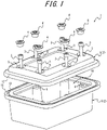
FIG. 1 is an exploded perspective view of an explosion-proof structure according to a first embodiment; -
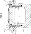
FIG. 2 is a cross-sectional view of the explosion-proof structure illustrated inFIG. 1 ; -
FIG. 3 is an enlarged view of part A ofFIG. 2 ; -
FIG. 4 is an exploded perspective view of an explosion-proof structure according to a second embodiment; and -
FIG. 5 is a cross-sectional view of the explosion-proof structure illustrated inFIG. 4 . - Embodiments of the present disclosure are described below with reference to the drawings.
- As illustrated in
FIGS. 1 to 3 , the explosion-proof structure 1 according to the first embodiment is formed by two internal space-formingmembers 2 and one or more (six in the present embodiment) pairs of afastener 3 and aplug 4. The two internal space-formingmembers 2 include one or more (six in the present embodiment) pairs of aninsertion hole 5 and afastening hole 6, corresponding in number to thefasteners 3 andplugs 4. In other words, the explosion-proof structure 1 includes one or more (six in the present embodiment) fasteningportions 7, each formed by afastener 3, aplug 4, aninsertion hole 5, and afastening hole 6. All of the fasteningportions 7 have the same structure and orientation. The two internal space-formingmembers 2, thefasteners 3, and theplugs 4 are each made of metal, for example. - The explosion-proof structure 1 according to the present embodiment is the structure of an explosion-proof container for a converter that forms a sensor device as a field device used in a plant. The explosion-proof structure 1 may, however, be the structure of a container for field devices other than such a converter.
- Field devices refer to sensor devices such as pressure gauges, flow meters, and temperature sensors; valve devices, such as flow control valves and opening/closing valves; actuator devices, such as fans or motors; image capturing devices, such as cameras and video recorders, that capture images of the conditions and objects in the plant; acoustic devices, such as microphones that collect abnormal noises and the like inside the plant and speakers that emit warning sounds or the like; position detectors that output positional information for various devices; and other such devices. The plant is an industrial plant such as a chemical plant; a plant for managing a well site, such as a gas field or oil field, and the surrounding area; a plant for managing power generation such as hydroelectric power, thermal power, nuclear power, or the like; a plant for managing environmental power generation such as solar power, wind power, or the like; a plant for managing water and sewage, a dam, or the like; or another type of plant.
- The two internal space-forming
members 2 are joined together to form aninternal space 10 by eachfastener 3 being inserted into aninsertion hole 5, provided in correspondence with thefastener 3 in one internal space-forming member 2 (hereinafter also referred to as a first member 8), and fastened to afastening hole 6, provided in correspondence with thefastener 3 in the other internal space-forming member 2 (hereinafter also referred to as a second member 9). In the present embodiment, thefirst member 8 is a lid, and thesecond member 9 is a housing, but this example is not limiting. Thefirst member 8 may be a housing, and thesecond member 9 may be a lid. - The
fastener 3 includes ashaft 3a that is fastened to thefastening hole 6 and ahead 3b that is larger in diameter than theshaft 3a. Thehead 3b includes an operable part (hereinafter referred to as a firstoperable part 3c), configured by a non-circular hole formed on the upper surface, to receive a rotational operation for fastening. Thefastener 3 is configured as a bolt, with theshaft 3a being a threaded shaft, and thefastening hole 6 is configured as a threaded hole. - In the present embodiment, the up-down direction refers to the direction along the central axis O of the
shaft 3a of the fastener 3 (e.g., the up-down direction inFIG. 2 ), the radial direction refers to the direction along a straight line orthogonal to the central axis O, and the circumferential direction refers to the direction around the central axis O. - The
plug 4 is attached to theinsertion hole 5 so as to cover thehead 3b of thefastener 3. Theplug 4 includes aplug body 4a that covers thehead 3b of thefastener 3 and aneave 4b that protrudes radially outward from the upper end of theplug body 4a and extends annularly in the circumferential direction. The portion of the outer circumferential surface of theplug body 4a other than the upper end includes amale thread 4c. The upper end of the outer circumferential surface of theplug body 4a includes acircumferential groove 4d extending annularly in the circumferential direction. An annular elastic sealing member (hereinafter referred to as a first sealing member 11) is provided across the entire circumference of thecircumferential groove 4d. The lower surface of theplug body 4a includes arecess 4e to accommodate thehead 3b. The upper surface of theplug body 4a includes an operable part (hereinafter referred to as a secondoperable part 4f), configured by a non-circular hole, to receive a rotational operation for fastening. The secondoperable part 4f has the same structure as the firstoperable part 3c. - The
insertion hole 5 is a through-hole. Theinsertion hole 5 includes afirst hole 5a that has an inner diameter smaller than the outer diameter of thehead 3b and equal to or greater than the outer diameter of theshaft 3a, asecond hole 5b that is connected to the upper end of thefirst hole 5a and has an inner diameter larger than the outer diameter of thehead 3b, and athird hole 5c that is connected to the upper end of thesecond hole 5b and has an inner diameter equal to or greater than the outer diameter of theeave 4b. - The inner circumferential surface of the
first hole 5a is a flat cylindrical surface. The bottom surface of thesecond hole 5b abuts against the bottom surface of thehead 3b. At least a portion of the inner circumferential surface of thesecond hole 5b other than the upper end includes afemale thread 5d into which themale thread 4c is screwed. The upper end of the inner circumferential surface of thesecond hole 5b is in close contact with the sealing member across the entire circumference thereof. The bottom surface of thethird hole 5c abuts against the bottom surface of theeave 4b. - The two internal space-forming
members 2 include twojoints 12 that are joined together by eachfastener 3 being inserted into theinsertion hole 5 corresponding to thefastener 3 and fastened to thefastening hole 6 corresponding to thefastener 3, and that form a ring extending along the outer periphery of theinternal space 10. One of thejoints 12 includes arecessed groove 13, on the joint surface, that forms a ring extending along the outer periphery of theinternal space 10. An annular elastic sealing member (hereinafter referred to as a second sealing member 14) is provided across the entire circumference of therecessed groove 13. Thesecond sealing member 14 is not illustrated inFIG. 1 , but only inFIG. 2 . Thesecond sealing member 14 is in close contact with the other joint 12 across the entire circumference thereof. Although thesecond member 9 includes the recessedgroove 13 in the present embodiment, this example is not limiting, and thefirst member 8 may be configured to include the recessedgroove 13. - The
first sealing member 11 and the second sealingmember 14 can each be provided for waterproofing, dustproofing, or the like. As long as explosion-proof performance can be ensured, a configuration without the first sealing member 11 (andperipheral groove 4d) and the second sealing member 14 (and recessed groove 13) may be adopted. - The
second member 9 includes the fastening holes 6 on theinternal space 10 side of the annular joint 12. In other words, thefastening portions 7 are located on theinternal space 10 side of the twojoints 12. The insertion holes 5 communicate with theinternal space 10. - According to the present embodiment, even when sufficient performance as the explosion-proof structure 1 cannot be achieved simply by fastening each
fastener 3, sufficient performance as the explosion-proof structure 1 can be achieved by further attaching eachplug 4 to theinsertion hole 5 corresponding to theplug 4. Therefore, the degree of freedom in arranging one ormore fastening portions 7 can be increased. For example, thefastening portions 7 can be arranged on theinternal space 10 side of the twojoints 12, as in the present embodiment. This makes it easier to achieve a reduction in size of the explosion-proof structure 1. Furthermore, a reduction in size of the explosion-proof structure 1 reduces the number offastening portions 7, thereby facilitating a reduction in cost. - According to the present embodiment, since the
plug 4 includes arecess 4e that accommodates thehead 3b, the depth of theinsertion hole 5 can be reduced and the thickness of thefastening portion 7 in the up-down direction can be reduced. - According to the present embodiment, good explosion-proof performance by the
plug 4 can be achieved, since theplug 4 has amale thread 4c. - In the first embodiment, the
first member 8 is a lid and thesecond member 9 is a housing. However, thefirst member 8 may be a window for maintenance work, and thesecond member 9 may be a lid, as in the second embodiment illustrated inFIGS. 4 to 5 . The explosion-proof structure 1 according to the second embodiment is the structure of a window of an explosion-proof container for a converter that forms a sensor device as a field device. The explosion-proof structure 1 may be the structure of a window in a container for field devices other than such a converter. - In the present embodiment, the
second member 9 includes the fastening holes 6 in the annular joint 12. In other words, thefastening portions 7 are located in the twojoints 12. The insertion holes 5 communicate with theinternal space 10 via a non-illustrated gap. In the present embodiment, eachinsertion hole 5 includes thefirst hole 5a and thesecond hole 5b, but does not include thethird hole 5c. The remaining configuration is similar to that of the first embodiment. - The same effects as in the first embodiment can be achieved by the present embodiment as well.
- The above embodiments are examples of the present disclosure, and a variety of modifications may be made.
- For example, the explosion-proof structure 1 according to the above embodiments can be modified in various ways, as described below.
- The explosion-proof structure 1 according to the above embodiments can be modified in various ways, as long as the explosion-proof structure 1 is formed by the
fastener 3, the two internal space-formingmembers 2 joined together to form theinternal space 10 by thefastener 3 being inserted into theinsertion hole 5 and fastened to thefastening hole 6, and theplug 4 attached to theinsertion hole 5 so as to cover thehead 3b of thefastener 3. - In the explosion-proof structure 1 according to the above embodiments, the
plug 4 preferably includes therecess 4e that accommodates thehead 3b. - In the explosion-proof structure 1 according to the above embodiments, the
plug 4 preferably includes themale thread 4c that screws into theinsertion hole 5. - In the explosion-proof structure 1 according to the above embodiments, the
fastener 3 is preferably configured as a bolt. - In the explosion-proof structure 1 according to the above embodiments, the
fastening hole 6 is preferably configured as a screw hole.
Claims (3)
- An explosion-proof structure formed by:a fastener;two internal space-forming members, joined together to form an internal space by the fastener being inserted into an insertion hole and fastened to a fastening hole; anda plug attached to the insertion hole so as to cover a head of the fastener.
- The explosion-proof structure of claim 1, wherein the plug comprises a recess to accommodate the head.
- The explosion-proof structure of claim 1 or 2, wherein the plug comprises a male thread that screws into the insertion hole.
Applications Claiming Priority (1)
| Application Number | Priority Date | Filing Date | Title |
|---|---|---|---|
| JP2021039702A JP7347463B2 (en) | 2021-03-11 | 2021-03-11 | Explosion-proof construction |
Publications (2)
| Publication Number | Publication Date |
|---|---|
| EP4056860A1 true EP4056860A1 (en) | 2022-09-14 |
| EP4056860B1 EP4056860B1 (en) | 2024-08-21 |
Family
ID=80787085
Family Applications (1)
| Application Number | Title | Priority Date | Filing Date |
|---|---|---|---|
| EP22158845.2A Active EP4056860B1 (en) | 2021-03-11 | 2022-02-25 | Explosion-proof structure |
Country Status (4)
| Country | Link |
|---|---|
| US (1) | US11905094B2 (en) |
| EP (1) | EP4056860B1 (en) |
| JP (1) | JP7347463B2 (en) |
| CN (1) | CN115087283B (en) |
Citations (3)
| Publication number | Priority date | Publication date | Assignee | Title |
|---|---|---|---|---|
| DE102013113158A1 (en) * | 2013-11-28 | 2015-05-28 | Ströter Antriebstechnik GmbH | Screw connection of a gearbox cover |
| DE102017211848A1 (en) * | 2017-07-11 | 2019-01-17 | Bayerische Motoren Werke Aktiengesellschaft | motor vehicle |
| CN209949663U (en) * | 2019-02-21 | 2020-01-14 | 山西全安新技术开发有限公司 | Device for fastening explosion-proof electrical equipment cavity |
Family Cites Families (14)
| Publication number | Priority date | Publication date | Assignee | Title |
|---|---|---|---|---|
| JPS6031130U (en) * | 1983-08-06 | 1985-03-02 | 株式会社 国産販売 | Explosion-proof junction box |
| JPH0430108Y2 (en) * | 1985-08-22 | 1992-07-21 | ||
| JPH0756526Y2 (en) * | 1991-02-08 | 1995-12-25 | 国際電気株式会社 | Explosion-proof container |
| JP3007520U (en) | 1994-08-05 | 1995-02-21 | 旭サカイ株式会社 | Sealing structure for screwing part |
| JPH1187941A (en) * | 1997-09-05 | 1999-03-30 | Hitachi Denshi Ltd | Explosion-proof container |
| JP4048167B2 (en) | 2003-12-24 | 2008-02-13 | 株式会社大同工業所 | Explosion-proof device |
| JP5733281B2 (en) | 2011-09-02 | 2015-06-10 | 日本精工株式会社 | Linear guide device, linear guide device cap position adjustment method, cap parts |
| JP6111660B2 (en) | 2012-12-28 | 2017-04-12 | 岩崎電気株式会社 | Explosion-proof lighting equipment |
| CN103711757B (en) * | 2013-12-13 | 2015-08-19 | 同济大学 | A kind of rotary double-nest unilateral bolt fastener |
| US20150285480A1 (en) * | 2014-04-08 | 2015-10-08 | Li-Hong Science & Technology Co., Ltd. | Led explosion-proof lamp |
| DE102014016052A1 (en) * | 2014-10-30 | 2016-05-04 | Hengstler Gmbh | Explosion-proof housing for a sensor |
| RU2687141C1 (en) * | 2015-08-25 | 2019-05-07 | Фенвал Контролз Оф Джэпэн, Лтд. | Photoelectric smoke detector |
| JP2019127057A (en) | 2018-01-22 | 2019-08-01 | 協永産業株式会社 | Cap member of wheel attachment nut and wheel attachment method |
| US11996578B2 (en) * | 2019-09-20 | 2024-05-28 | Gs Yuasa International Ltd. | Vent plug for lead-acid battery and lead-acid battery |
-
2021
- 2021-03-11 JP JP2021039702A patent/JP7347463B2/en active Active
-
2022
- 2022-02-15 US US17/651,144 patent/US11905094B2/en active Active
- 2022-02-25 EP EP22158845.2A patent/EP4056860B1/en active Active
- 2022-02-28 CN CN202210185452.6A patent/CN115087283B/en active Active
Patent Citations (3)
| Publication number | Priority date | Publication date | Assignee | Title |
|---|---|---|---|---|
| DE102013113158A1 (en) * | 2013-11-28 | 2015-05-28 | Ströter Antriebstechnik GmbH | Screw connection of a gearbox cover |
| DE102017211848A1 (en) * | 2017-07-11 | 2019-01-17 | Bayerische Motoren Werke Aktiengesellschaft | motor vehicle |
| CN209949663U (en) * | 2019-02-21 | 2020-01-14 | 山西全安新技术开发有限公司 | Device for fastening explosion-proof electrical equipment cavity |
Also Published As
| Publication number | Publication date |
|---|---|
| CN115087283A (en) | 2022-09-20 |
| JP2022139363A (en) | 2022-09-26 |
| US20220289452A1 (en) | 2022-09-15 |
| CN115087283B (en) | 2024-11-22 |
| EP4056860B1 (en) | 2024-08-21 |
| JP7347463B2 (en) | 2023-09-20 |
| US11905094B2 (en) | 2024-02-20 |
Similar Documents
| Publication | Publication Date | Title |
|---|---|---|
| CN207300485U (en) | Hydrostatic sensor mounting structure | |
| CN108352651B (en) | sealing cap | |
| US11018485B2 (en) | Explosion-proof structure | |
| TWI701166B (en) | Tire condition monitoring device | |
| EP4056860B1 (en) | Explosion-proof structure | |
| EP3749071B1 (en) | Electrical device and component for electrical device | |
| JP7238373B2 (en) | sealed container | |
| US11652271B2 (en) | Substrate storage structure | |
| CN205900952U (en) | A electron device for gathering seismic data | |
| JP2018133913A (en) | Electric connection structure | |
| JP6909704B2 (en) | Fluid control valve | |
| JP6082648B2 (en) | connector | |
| JP2762415B2 (en) | Position detector cable connection structure | |
| JP2008187834A (en) | Fastening member, fastening structure, and motor | |
| JP4287524B2 (en) | Valve box seal structure | |
| CN218412885U (en) | Laser radar device and navigation robot | |
| CN214618134U (en) | Valve signal-back device | |
| CN222255226U (en) | Electric valve | |
| CN216284082U (en) | Gauge head sealing structure of pressure transmitter | |
| CN213711877U (en) | Seal structure and seal system | |
| CN110173366A (en) | The sealing structure of engine, cylinder jacket, cylinder cap and cylinder jacket and cylinder cap | |
| JP4285260B2 (en) | Waterproof electronic equipment | |
| JP2020068557A (en) | Mounting member | |
| JP2020068556A (en) | Cable gland | |
| TWM624954U (en) | Device with waterproof joint |
Legal Events
| Date | Code | Title | Description |
|---|---|---|---|
| PUAI | Public reference made under article 153(3) epc to a published international application that has entered the european phase |
Free format text: ORIGINAL CODE: 0009012 |
|
| STAA | Information on the status of an ep patent application or granted ep patent |
Free format text: STATUS: THE APPLICATION HAS BEEN PUBLISHED |
|
| AK | Designated contracting states |
Kind code of ref document: A1 Designated state(s): AL AT BE BG CH CY CZ DE DK EE ES FI FR GB GR HR HU IE IS IT LI LT LU LV MC MK MT NL NO PL PT RO RS SE SI SK SM TR |
|
| STAA | Information on the status of an ep patent application or granted ep patent |
Free format text: STATUS: REQUEST FOR EXAMINATION WAS MADE |
|
| 17P | Request for examination filed |
Effective date: 20230309 |
|
| RBV | Designated contracting states (corrected) |
Designated state(s): AL AT BE BG CH CY CZ DE DK EE ES FI FR GB GR HR HU IE IS IT LI LT LU LV MC MK MT NL NO PL PT RO RS SE SI SK SM TR |
|
| P01 | Opt-out of the competence of the unified patent court (upc) registered |
Effective date: 20230606 |
|
| GRAP | Despatch of communication of intention to grant a patent |
Free format text: ORIGINAL CODE: EPIDOSNIGR1 |
|
| STAA | Information on the status of an ep patent application or granted ep patent |
Free format text: STATUS: GRANT OF PATENT IS INTENDED |
|
| RIC1 | Information provided on ipc code assigned before grant |
Ipc: F16B 37/14 20060101ALN20240227BHEP Ipc: F16B 33/00 20060101ALN20240227BHEP Ipc: F16B 5/02 20060101AFI20240227BHEP |
|
| RIC1 | Information provided on ipc code assigned before grant |
Ipc: F16B 37/14 20060101ALN20240301BHEP Ipc: F16B 33/00 20060101ALN20240301BHEP Ipc: F16B 5/02 20060101AFI20240301BHEP |
|
| INTG | Intention to grant announced |
Effective date: 20240322 |
|
| GRAS | Grant fee paid |
Free format text: ORIGINAL CODE: EPIDOSNIGR3 |
|
| GRAA | (expected) grant |
Free format text: ORIGINAL CODE: 0009210 |
|
| STAA | Information on the status of an ep patent application or granted ep patent |
Free format text: STATUS: THE PATENT HAS BEEN GRANTED |
|
| AK | Designated contracting states |
Kind code of ref document: B1 Designated state(s): AL AT BE BG CH CY CZ DE DK EE ES FI FR GB GR HR HU IE IS IT LI LT LU LV MC MK MT NL NO PL PT RO RS SE SI SK SM TR |
|
| REG | Reference to a national code |
Ref country code: GB Ref legal event code: FG4D |
|
| REG | Reference to a national code |
Ref country code: CH Ref legal event code: EP |
|
| REG | Reference to a national code |
Ref country code: IE Ref legal event code: FG4D |
|
| REG | Reference to a national code |
Ref country code: DE Ref legal event code: R096 Ref document number: 602022005393 Country of ref document: DE |
|
| REG | Reference to a national code |
Ref country code: LT Ref legal event code: MG9D |
|
| REG | Reference to a national code |
Ref country code: NL Ref legal event code: MP Effective date: 20240821 |
|
| PG25 | Lapsed in a contracting state [announced via postgrant information from national office to epo] |
Ref country code: NO Free format text: LAPSE BECAUSE OF FAILURE TO SUBMIT A TRANSLATION OF THE DESCRIPTION OR TO PAY THE FEE WITHIN THE PRESCRIBED TIME-LIMIT Effective date: 20241121 |
|
| REG | Reference to a national code |
Ref country code: AT Ref legal event code: MK05 Ref document number: 1715722 Country of ref document: AT Kind code of ref document: T Effective date: 20240821 |
|
| PG25 | Lapsed in a contracting state [announced via postgrant information from national office to epo] |
Ref country code: FI Free format text: LAPSE BECAUSE OF FAILURE TO SUBMIT A TRANSLATION OF THE DESCRIPTION OR TO PAY THE FEE WITHIN THE PRESCRIBED TIME-LIMIT Effective date: 20240821 Ref country code: NL Free format text: LAPSE BECAUSE OF FAILURE TO SUBMIT A TRANSLATION OF THE DESCRIPTION OR TO PAY THE FEE WITHIN THE PRESCRIBED TIME-LIMIT Effective date: 20240821 Ref country code: PL Free format text: LAPSE BECAUSE OF FAILURE TO SUBMIT A TRANSLATION OF THE DESCRIPTION OR TO PAY THE FEE WITHIN THE PRESCRIBED TIME-LIMIT Effective date: 20240821 Ref country code: PT Free format text: LAPSE BECAUSE OF FAILURE TO SUBMIT A TRANSLATION OF THE DESCRIPTION OR TO PAY THE FEE WITHIN THE PRESCRIBED TIME-LIMIT Effective date: 20241223 Ref country code: GR Free format text: LAPSE BECAUSE OF FAILURE TO SUBMIT A TRANSLATION OF THE DESCRIPTION OR TO PAY THE FEE WITHIN THE PRESCRIBED TIME-LIMIT Effective date: 20241122 |
|
| PG25 | Lapsed in a contracting state [announced via postgrant information from national office to epo] |
Ref country code: BG Free format text: LAPSE BECAUSE OF FAILURE TO SUBMIT A TRANSLATION OF THE DESCRIPTION OR TO PAY THE FEE WITHIN THE PRESCRIBED TIME-LIMIT Effective date: 20240821 |
|
| PG25 | Lapsed in a contracting state [announced via postgrant information from national office to epo] |
Ref country code: LV Free format text: LAPSE BECAUSE OF FAILURE TO SUBMIT A TRANSLATION OF THE DESCRIPTION OR TO PAY THE FEE WITHIN THE PRESCRIBED TIME-LIMIT Effective date: 20240821 |
|
| PG25 | Lapsed in a contracting state [announced via postgrant information from national office to epo] |
Ref country code: AT Free format text: LAPSE BECAUSE OF FAILURE TO SUBMIT A TRANSLATION OF THE DESCRIPTION OR TO PAY THE FEE WITHIN THE PRESCRIBED TIME-LIMIT Effective date: 20240821 Ref country code: IS Free format text: LAPSE BECAUSE OF FAILURE TO SUBMIT A TRANSLATION OF THE DESCRIPTION OR TO PAY THE FEE WITHIN THE PRESCRIBED TIME-LIMIT Effective date: 20241221 |
|
| PG25 | Lapsed in a contracting state [announced via postgrant information from national office to epo] |
Ref country code: HR Free format text: LAPSE BECAUSE OF FAILURE TO SUBMIT A TRANSLATION OF THE DESCRIPTION OR TO PAY THE FEE WITHIN THE PRESCRIBED TIME-LIMIT Effective date: 20240821 |
|
| PG25 | Lapsed in a contracting state [announced via postgrant information from national office to epo] |
Ref country code: ES Free format text: LAPSE BECAUSE OF FAILURE TO SUBMIT A TRANSLATION OF THE DESCRIPTION OR TO PAY THE FEE WITHIN THE PRESCRIBED TIME-LIMIT Effective date: 20240821 Ref country code: RS Free format text: LAPSE BECAUSE OF FAILURE TO SUBMIT A TRANSLATION OF THE DESCRIPTION OR TO PAY THE FEE WITHIN THE PRESCRIBED TIME-LIMIT Effective date: 20241121 |
|
| PG25 | Lapsed in a contracting state [announced via postgrant information from national office to epo] |
Ref country code: RS Free format text: LAPSE BECAUSE OF FAILURE TO SUBMIT A TRANSLATION OF THE DESCRIPTION OR TO PAY THE FEE WITHIN THE PRESCRIBED TIME-LIMIT Effective date: 20241121 Ref country code: PT Free format text: LAPSE BECAUSE OF FAILURE TO SUBMIT A TRANSLATION OF THE DESCRIPTION OR TO PAY THE FEE WITHIN THE PRESCRIBED TIME-LIMIT Effective date: 20241223 Ref country code: PL Free format text: LAPSE BECAUSE OF FAILURE TO SUBMIT A TRANSLATION OF THE DESCRIPTION OR TO PAY THE FEE WITHIN THE PRESCRIBED TIME-LIMIT Effective date: 20240821 Ref country code: NO Free format text: LAPSE BECAUSE OF FAILURE TO SUBMIT A TRANSLATION OF THE DESCRIPTION OR TO PAY THE FEE WITHIN THE PRESCRIBED TIME-LIMIT Effective date: 20241121 Ref country code: NL Free format text: LAPSE BECAUSE OF FAILURE TO SUBMIT A TRANSLATION OF THE DESCRIPTION OR TO PAY THE FEE WITHIN THE PRESCRIBED TIME-LIMIT Effective date: 20240821 Ref country code: LV Free format text: LAPSE BECAUSE OF FAILURE TO SUBMIT A TRANSLATION OF THE DESCRIPTION OR TO PAY THE FEE WITHIN THE PRESCRIBED TIME-LIMIT Effective date: 20240821 Ref country code: IS Free format text: LAPSE BECAUSE OF FAILURE TO SUBMIT A TRANSLATION OF THE DESCRIPTION OR TO PAY THE FEE WITHIN THE PRESCRIBED TIME-LIMIT Effective date: 20241221 Ref country code: HR Free format text: LAPSE BECAUSE OF FAILURE TO SUBMIT A TRANSLATION OF THE DESCRIPTION OR TO PAY THE FEE WITHIN THE PRESCRIBED TIME-LIMIT Effective date: 20240821 Ref country code: GR Free format text: LAPSE BECAUSE OF FAILURE TO SUBMIT A TRANSLATION OF THE DESCRIPTION OR TO PAY THE FEE WITHIN THE PRESCRIBED TIME-LIMIT Effective date: 20241122 Ref country code: FI Free format text: LAPSE BECAUSE OF FAILURE TO SUBMIT A TRANSLATION OF THE DESCRIPTION OR TO PAY THE FEE WITHIN THE PRESCRIBED TIME-LIMIT Effective date: 20240821 Ref country code: ES Free format text: LAPSE BECAUSE OF FAILURE TO SUBMIT A TRANSLATION OF THE DESCRIPTION OR TO PAY THE FEE WITHIN THE PRESCRIBED TIME-LIMIT Effective date: 20240821 Ref country code: BG Free format text: LAPSE BECAUSE OF FAILURE TO SUBMIT A TRANSLATION OF THE DESCRIPTION OR TO PAY THE FEE WITHIN THE PRESCRIBED TIME-LIMIT Effective date: 20240821 Ref country code: AT Free format text: LAPSE BECAUSE OF FAILURE TO SUBMIT A TRANSLATION OF THE DESCRIPTION OR TO PAY THE FEE WITHIN THE PRESCRIBED TIME-LIMIT Effective date: 20240821 |
|
| PG25 | Lapsed in a contracting state [announced via postgrant information from national office to epo] |
Ref country code: DK Free format text: LAPSE BECAUSE OF FAILURE TO SUBMIT A TRANSLATION OF THE DESCRIPTION OR TO PAY THE FEE WITHIN THE PRESCRIBED TIME-LIMIT Effective date: 20240821 Ref country code: SM Free format text: LAPSE BECAUSE OF FAILURE TO SUBMIT A TRANSLATION OF THE DESCRIPTION OR TO PAY THE FEE WITHIN THE PRESCRIBED TIME-LIMIT Effective date: 20240821 Ref country code: RO Free format text: LAPSE BECAUSE OF FAILURE TO SUBMIT A TRANSLATION OF THE DESCRIPTION OR TO PAY THE FEE WITHIN THE PRESCRIBED TIME-LIMIT Effective date: 20240821 |
|
| PG25 | Lapsed in a contracting state [announced via postgrant information from national office to epo] |
Ref country code: EE Free format text: LAPSE BECAUSE OF FAILURE TO SUBMIT A TRANSLATION OF THE DESCRIPTION OR TO PAY THE FEE WITHIN THE PRESCRIBED TIME-LIMIT Effective date: 20240821 |
|
| PG25 | Lapsed in a contracting state [announced via postgrant information from national office to epo] |
Ref country code: CZ Free format text: LAPSE BECAUSE OF FAILURE TO SUBMIT A TRANSLATION OF THE DESCRIPTION OR TO PAY THE FEE WITHIN THE PRESCRIBED TIME-LIMIT Effective date: 20240821 |
|
| PG25 | Lapsed in a contracting state [announced via postgrant information from national office to epo] |
Ref country code: IT Free format text: LAPSE BECAUSE OF FAILURE TO SUBMIT A TRANSLATION OF THE DESCRIPTION OR TO PAY THE FEE WITHIN THE PRESCRIBED TIME-LIMIT Effective date: 20240821 Ref country code: SK Free format text: LAPSE BECAUSE OF FAILURE TO SUBMIT A TRANSLATION OF THE DESCRIPTION OR TO PAY THE FEE WITHIN THE PRESCRIBED TIME-LIMIT Effective date: 20240821 |
|
| REG | Reference to a national code |
Ref country code: DE Ref legal event code: R097 Ref document number: 602022005393 Country of ref document: DE |
|
| PLBE | No opposition filed within time limit |
Free format text: ORIGINAL CODE: 0009261 |
|
| STAA | Information on the status of an ep patent application or granted ep patent |
Free format text: STATUS: NO OPPOSITION FILED WITHIN TIME LIMIT |
|
| 26N | No opposition filed |
Effective date: 20250522 |
|
| PG25 | Lapsed in a contracting state [announced via postgrant information from national office to epo] |
Ref country code: SE Free format text: LAPSE BECAUSE OF FAILURE TO SUBMIT A TRANSLATION OF THE DESCRIPTION OR TO PAY THE FEE WITHIN THE PRESCRIBED TIME-LIMIT Effective date: 20240821 |
|
| PG25 | Lapsed in a contracting state [announced via postgrant information from national office to epo] |
Ref country code: MC Free format text: LAPSE BECAUSE OF FAILURE TO SUBMIT A TRANSLATION OF THE DESCRIPTION OR TO PAY THE FEE WITHIN THE PRESCRIBED TIME-LIMIT Effective date: 20240821 |
|
| REG | Reference to a national code |
Ref country code: CH Ref legal event code: PL |
|
| PG25 | Lapsed in a contracting state [announced via postgrant information from national office to epo] |
Ref country code: LU Free format text: LAPSE BECAUSE OF NON-PAYMENT OF DUE FEES Effective date: 20250225 |
|
| PG25 | Lapsed in a contracting state [announced via postgrant information from national office to epo] |
Ref country code: CH Free format text: LAPSE BECAUSE OF NON-PAYMENT OF DUE FEES Effective date: 20250228 |
|
| REG | Reference to a national code |
Ref country code: BE Ref legal event code: MM Effective date: 20250228 |
|
| PG25 | Lapsed in a contracting state [announced via postgrant information from national office to epo] |
Ref country code: FR Free format text: LAPSE BECAUSE OF NON-PAYMENT OF DUE FEES Effective date: 20250228 |
|
| PG25 | Lapsed in a contracting state [announced via postgrant information from national office to epo] |
Ref country code: BE Free format text: LAPSE BECAUSE OF NON-PAYMENT OF DUE FEES Effective date: 20250228 |
|
| PG25 | Lapsed in a contracting state [announced via postgrant information from national office to epo] |
Ref country code: IE Free format text: LAPSE BECAUSE OF NON-PAYMENT OF DUE FEES Effective date: 20250225 |
|
| PGFP | Annual fee paid to national office [announced via postgrant information from national office to epo] |
Ref country code: DE Payment date: 20260121 Year of fee payment: 5 |