EP4056859A1 - A method of operating a pipework aggregate, an assembly for attenuation of vibration of a pump unit coupled to a pipework aggregate and a pump unit - Google Patents
A method of operating a pipework aggregate, an assembly for attenuation of vibration of a pump unit coupled to a pipework aggregate and a pump unit Download PDFInfo
- Publication number
- EP4056859A1 EP4056859A1 EP21162309.5A EP21162309A EP4056859A1 EP 4056859 A1 EP4056859 A1 EP 4056859A1 EP 21162309 A EP21162309 A EP 21162309A EP 4056859 A1 EP4056859 A1 EP 4056859A1
- Authority
- EP
- European Patent Office
- Prior art keywords
- pump unit
- pipework
- base plate
- aggregate
- foundation
- Prior art date
- Legal status (The legal status is an assumption and is not a legal conclusion. Google has not performed a legal analysis and makes no representation as to the accuracy of the status listed.)
- Granted
Links
Images





Classifications
-
- F—MECHANICAL ENGINEERING; LIGHTING; HEATING; WEAPONS; BLASTING
- F04—POSITIVE - DISPLACEMENT MACHINES FOR LIQUIDS; PUMPS FOR LIQUIDS OR ELASTIC FLUIDS
- F04D—NON-POSITIVE-DISPLACEMENT PUMPS
- F04D29/00—Details, component parts, or accessories
- F04D29/66—Combating cavitation, whirls, noise, vibration or the like; Balancing
- F04D29/669—Combating cavitation, whirls, noise, vibration or the like; Balancing especially adapted for liquid pumps
-
- F—MECHANICAL ENGINEERING; LIGHTING; HEATING; WEAPONS; BLASTING
- F04—POSITIVE - DISPLACEMENT MACHINES FOR LIQUIDS; PUMPS FOR LIQUIDS OR ELASTIC FLUIDS
- F04D—NON-POSITIVE-DISPLACEMENT PUMPS
- F04D15/00—Control, e.g. regulation, of pumps, pumping installations or systems
-
- F—MECHANICAL ENGINEERING; LIGHTING; HEATING; WEAPONS; BLASTING
- F04—POSITIVE - DISPLACEMENT MACHINES FOR LIQUIDS; PUMPS FOR LIQUIDS OR ELASTIC FLUIDS
- F04D—NON-POSITIVE-DISPLACEMENT PUMPS
- F04D29/00—Details, component parts, or accessories
- F04D29/60—Mounting; Assembling; Disassembling
- F04D29/605—Mounting; Assembling; Disassembling specially adapted for liquid pumps
-
- F—MECHANICAL ENGINEERING; LIGHTING; HEATING; WEAPONS; BLASTING
- F05—INDEXING SCHEMES RELATING TO ENGINES OR PUMPS IN VARIOUS SUBCLASSES OF CLASSES F01-F04
- F05D—INDEXING SCHEME FOR ASPECTS RELATING TO NON-POSITIVE-DISPLACEMENT MACHINES OR ENGINES, GAS-TURBINES OR JET-PROPULSION PLANTS
- F05D2260/00—Function
- F05D2260/85—Starting
-
- F—MECHANICAL ENGINEERING; LIGHTING; HEATING; WEAPONS; BLASTING
- F05—INDEXING SCHEMES RELATING TO ENGINES OR PUMPS IN VARIOUS SUBCLASSES OF CLASSES F01-F04
- F05D—INDEXING SCHEME FOR ASPECTS RELATING TO NON-POSITIVE-DISPLACEMENT MACHINES OR ENGINES, GAS-TURBINES OR JET-PROPULSION PLANTS
- F05D2270/00—Control
- F05D2270/30—Control parameters, e.g. input parameters
- F05D2270/303—Temperature
Definitions
- stiffness and/or damping of support of the base plate of the pump unit on the foundation is restored to the state prevailing in the transient state.
- An assembly for attenuation of vibration of a pump unit coupled to a pipework comprising a centrifugal pump and a motor assembled on a base plate, the pump unit being supported resiliently on a foundation using a resilient support, which resilient support is resilient several directions.
- the assembly comprises a retainer means configured movable between a first position suppressing relative movement between the foundation and the base plate for increasing stiffness and/or damping and/or damping of support of the base plate of the pump unit on the foundation, a second position being neutral in influencing to relative movement between the foundation and the base plate.
- the base plate is supported on the foundation by several vertical legs wherein the resilient support is arranged between the leg and the base plate, and the retainer means are arranged to selectably supress relative movement between the leg and the base plate in the plane of the base plate.
- the retainer means are provided with a body part, and pusher part adjustably attached to the body part, wherein the relative movement between the leg and the base plate is suppressible by bringing the pusher part against either one of the base plate or the leg while the body part being attached to either one of the base plate or the leg.
- body part is attached to the base plate and the pusher part is configured to adjustably push against the leg.
- the pusher part comprises a screw bar and the body part comprises a threaded hole to which the screw bar is attached, and that the pusher part is provided with a resilient head at an end of the screw bar.
- the resilient support are compression springs.
- a pump unit comprising an assembly for attenuation of vibration according to the invention.
- base plate means a generally planar structure on which a centrifugal pump and its motor are assembled.
- the base plate may be a framework which is constructed of multiple beams arranged to form the planar structure.
- the pump unit comprises a resilient support 24 in the base plate 20, such that the pump unit 10 is supported resiliently on the foundation 22.
- the resilient support 24 is resilient several directions.
- the resilient support may comprise one of, or a combination of a spring, resilient block, such as a rubber block, vibration damper, such as viscose damper, or alike.
- the resilient support is a compression spring 25.
- the resilient support has a main compression direction which is bearing the load caused by the mass of the pump unit 10. The main compression direction is therefore substantially vertical direction transverse to the plane or the base plate 20.
- the pump 14 is connected to the pipework aggregate without any bellows, that is using simple flange joint 14.2 directly to respective feed pipe 14.1 and return pipe 14.3. Such a flange joint may be considered as a rigid coupling. At least the flange joint 14.2. is considerably stiffer than the resilient support 24.
- FIG. 2 shows a side view of a pump unit 10 according to an embodiment of the invention.
- FIG. 3 shows a left-side end view of the Figure 2 .
- FIG. 5 shows a sectional view V-V marked in the figure 3 which is in turn shown in the Figure 5 .
- the pump unit 10 comprises an assembly 26 for attenuation of vibration of a pump unit to selectably effect on the resilient support 24 in the base plate 20 and vibration characteristics of the pump unit 10.
- the assembly 26 comprises adjustable retainer means 28 for increasing stiffness and/or damping of support of the base plate of the pump unit on the foundation.
- the retainer means 28 can be selectably activated for effecting on the stiffness and/or damping of support of the base plate and deactivated. In addition to mere on-off action of being activate or passive, the stiffness is adjustable by adjusting the force by which the retainer means 28 effects.
- FIG. 7 there is shown an enlarged view A in the figure 6 , which shows one of the resilient supports 24 in connection with which two retainer means 28 are arranged.
- the retainer means 28 are arranged as pairs in which the retainer means 28.1'-28.1" effect in opposite directions to each other.
- the first pair of retainer means 28.1'-28.1" is arranged to effect in the direction of the selected direction, and a second pair of retainer means 28.3' - 28.3" is arranged to effect in the direction perpendicularly to the selected direction.
- the retainer means 28 are provided with a body part 32, and a pusher part 34 adjustably attached to the body part 32, wherein the relative movement between the leg 30 and the base plate 20 is suppressible by bringing the pusher part 34 against either one of the base plate 20 or the leg 32 while the body part 32 being attached to either one of the base plate 20 or the leg 32.
- the pusher part 34 is brought against the other one of the base plate 20 or the leg 32.
- the body part 32 of the retainer means 28 is attached by screws to the base plate 20 and the pusher part 34 is brought against a surface of the leg 32.
- the pusher part is configured to adjustably push against the leg.
- the pusher part is configured to be selectably activated, by bring it against the leg 32, and deactivated by detaching the pusher part 34 from the leg 32, and when activated the pressing force of the pusher part is adjustable.
- the pusher part 34 comprises a screw bar and the body part comprises a threaded hole 36 to which the screw bar is attached so as to provide adjustable longitudinal movement of the screw bar by rotation thereof.
- the pusher part 34 is provided with a resilient head 38 at an end of the screw bar 34.
- the surface in the leg, against which the pushed part 34 is pushing can be provided with an optional, additional counter part 40, by means of the characteristics of the support can be further controlled.
- the counter part 40 may be for a resilient block or a plate.
- the counter part 40 may be arranged in connection with one or more, or all of the pusher parts 34.
- stiffness and/or damping of support of the base plate of the pump unit on the foundation is increased, such that stiffness and/or damping of support of the pump unit 10 on the foundation is ruled in addition to the resilient support, by means of the pusher part 34, as is depicted in the figure 7 .
- the retainer means 28 it is possible to minimize excessive vibration of the pump unit 10 induced by excitations from the pipework.
- the resilient support results in advanced operation during the start-up stage compensating heat expansion of the pipework aggregate, while during the steady state operation, when the operational temperature has been reached, increased stiffness and/or damping is brought by the pusher part minimizing excessive vibration of the pump unit 10.
- the method may include a step of setting a target operational temperature to the process fluid and/or the pipework aggregate, and acquiring a measured temperature of the process fluid and/or the pipework aggregate, and in case the measured temperature is lower than the target operational temperature the pipework aggregate is in a transient state operation, and in case the measured temperature is equal to or higher than the target operational temperature, the pipework aggregate is in a steady state operation.
- Each one of the retainer means 28 effects in one direction in the plane of the base plate 20.
- the assembly comprises a pole 42 which is attached to the foundation 20 similarly to the legs 30 of the pump unit 10. In practise the surface at the end of the pole 42 in the figure 9 is attached to the foundation.
- the pole extends upwardly from the foundation into the plane of the base plate 20 between its structural beams.
- the body part 48 is provided with a pusher screw 50 by means of which the position of the wedge part 46 can be changed. Movement of the wedge part 46 tightens the wedge-shaped space between the support block 44 and the body part 48, and this way effects on the stiffness and/or damping of support of the base plate 20.
- the contact may be arranged as a gliding contact by arranging a suitable glide part to either one, or both of the surface.
- FIG 11 discloses a view of a pump unit 10 from beneath the pump unit 10 according to another embodiment of the invention.
- the pump unit 10 comprises an alternative assembly 26 for attenuation of vibration of a pump unit to selectably effect on the resilient support 24 in the base plate 20 and vibration characteristics of the pump unit 10.
- the assembly 26 comprises four retainer means 28 for increasing stiffness and/or damping of support of the base plate of the pump unit on the foundation.
- vibration of the pump unit is analysed during the transient state operation and if at least one direction of vibration, which has vibration amplitude greater than a pre-set limit value of the amplitude, is determined, stiffness and/or damping of the base plate of the pump unit is increased in at least the determined direction of vibration.
- stiffness and/or damping of support of the base plate of the pump unit on the foundation is increased by arranging a mechanical retainer means to suppress relative movement between the base plate and the foundation in the determined direction of vibration.
- Change of the fluid characteristics is change of temperature and operation is steady state operation when the temperature has reached a predetermined temperature level.
Landscapes
- Engineering & Computer Science (AREA)
- Mechanical Engineering (AREA)
- General Engineering & Computer Science (AREA)
- Vibration Prevention Devices (AREA)
- Structures Of Non-Positive Displacement Pumps (AREA)
Abstract
Description
- The present invention relates to method of operating a pipework aggregate according to the preamble of the claim 1.
- The present invention relates to an assembly for attenuation of vibration of a pump unit coupled to a pipework according to the preamble of the claim 8.
- The present invention relates also to a pump unit.
- Invention relates to vibration problems in a pipework aggregate to which a pump unit is attached to pump the fluid in the pipework.
- A pump is usually installed in a bed or a support frame typically made of metal bars. The support frame is resiliently attached to a foundation. The foundation may be for example a concrete floor or a separate framework made of metal bars.
-
KR1020200087114A - It has been found out that even if such a pump unit and the support frame would be aqeuately supported to the mounting frame, coupling it with the pipework changes the vibration properties of the whole system considerably and the support of the mounting frame can not adequately cope with the whole system comprsing the pipework aggregate, which includes the pump unit. Structural dynamics of such pipework aggregate changes from the standstill situation to operational situation and structual dynamics of the pipework aggregate is difficult to define exactly beforehand. On the otherhand, the circustances during a steady state operation of the pipework aggregate are diffent and therefore the support which may be optimal for start-up stage may be unadequate in steady state operation.
- An object of the invention is to provide a method of operating a pipework aggregate and an assembly for attenuation of vibration of a pump unit in which the performance is considerably improved compared to the prior art solutions.
- It is also an object of the invention is to provide a pump unit utilizing the method and/or the assembly.
- Objects of the invention can be met substantially as is disclosed in the independent claims and in the other claims describing more details of different embodiments of the invention.
- According to an embodiment of the method of operating a pipework aggregate, comprising a pipework for transporting process fluid, fluid processing devices and at least one pump unit, comprising a centrifugal pump and a motor assembled on a base plate, the pump unit being coupled to the pipework, which pump unit is supported resiliently on a foundation using a resilient support, which resilient support is resilient in several directions, comprises steps of
- when the process fluid flow in the pipework aggregate is in a transient state operation, during which vibration properties of the pipework aggregate change due to change of the fluid characteristics, stiffness and/or damping of support of the pump unit on the foundation is ruled by the resilient support, and
- when the process fluid flow is in a steady state operation stiffness and/or damping of support of the pump unit on the foundation is increased.
- This way operation of the pump unit advantageous during both the transient state operation, such as start-up, and during steady state operation. During the start-up stage vibration behaviour and/or thermal expansions of the pipework aggregate and its effects on the pump unit is advantageously taken care by the resilient support, while during the steady state the stiffness and/or damping of support of the pump unit on the foundation is increased so as to minimize the harmful effects of any vibration resonances.
- According to an embodiment of the invention the method further comprises
- Setting a target operational temperature to the process fluid and/or the pipework aggregate, and acquiring a measured temperature of the process fluid and/or the pipework aggregate, and
- in case the measured temperature is lower than the target operational temperature the pipework aggregate is in a transient state operation, and
- in case the measured temperature is equal to or higher than the target operational temperature, the pipework aggregate is in a steady state operation and stiffness and/or damping of support of the pump unit on the foundation is increased.
- Resilient support is arranged for coping with temperature increase while the temperature is lower than the target temperature. During normal operation the resilient support is prone to allow inducement of vibrations and when the measured temperature is equal to or higher than the target operational temperature, the pipework aggregate is in a steady state operation and stiffness and/or damping of support of the pump unit on the foundation is increased.
- According to an embodiment of the invention the method further comprises during a start-up of the pipework aggregate.
- the motor is started to run the pump and the fluid in the pipework aggregate starts the transportation of the fluid in transient state operation, and
- when the process fluid flow is in a steady state operation stiffness and/or damping of support of the base plate of the pump unit on the foundation is increased, and
- in a next shut-down of the pipework aggregate transient state operation is commenced and stiffness and/or damping of support of the base plate of the pump unit on the foundation is restored to the state prevailing in the transient state.
- According to an embodiment of the invention during the steady state operation, vibration of the pump unit is analysed, and if direction of vibration, which has vibration amplitude greater than a pre-set limit value of the amplitude, is detected, stiffness and/or damping of the base plate of the pump unit is increased in at least the determined direction of vibration.
- According to an embodiment of the invention stiffness and/or damping of support of the base plate of the pump unit on the foundation is increased by arranging a mechanical retainer means to selectably suppress relative movement between the base plate and the foundation in the determined direction of vibration.
- According to an embodiment of the invention during the steady state operation, stiffness and/or damping of the support of the base plate of the pump unit is adjust-ably increased in a plane of the base plate.
- According to an embodiment of the invention in a next transient state operation after a steady state operation, stiffness and/or damping of support of the base plate of the pump unit on the foundation is restored to the state prevailing in the transient state.
- An assembly for attenuation of vibration of a pump unit coupled to a pipework, the pump unit comprising a centrifugal pump and a motor assembled on a base plate, the pump unit being supported resiliently on a foundation using a resilient support, which resilient support is resilient several directions. The assembly comprises a retainer means configured movable between a first position suppressing relative movement between the foundation and the base plate for increasing stiffness and/or damping and/or damping of support of the base plate of the pump unit on the foundation, a second position being neutral in influencing to relative movement between the foundation and the base plate.
- According to an embodiment of the invention the base plate is supported on the foundation by several vertical legs wherein the resilient support is arranged between the leg and the base plate, and the retainer means are arranged to selectably supress relative movement between the leg and the base plate in the plane of the base plate.
- According to an embodiment of the invention the retainer means are provided with a body part, and pusher part adjustably attached to the body part, wherein the relative movement between the leg and the base plate is suppressible by bringing the pusher part against either one of the base plate or the leg while the body part being attached to either one of the base plate or the leg.
- According to an embodiment of the invention body part is attached to the base plate and the pusher part is configured to adjustably push against the leg.
- According to an embodiment of the invention that the pusher part comprises a screw bar and the body part comprises a threaded hole to which the screw bar is attached, and that the pusher part is provided with a resilient head at an end of the screw bar.
- According to an embodiment of the invention the resilient support are compression springs.
- According to an embodiment of the invention the retainer means are arranged as pairs in which the retainer means in each pair effect in opposite directions to each other.
- A pump unit comprising an assembly for attenuation of vibration according to the invention.
- In this context the term base plate means a generally planar structure on which a centrifugal pump and its motor are assembled. The base plate may be a framework which is constructed of multiple beams arranged to form the planar structure.
- The exemplary embodiments of the invention presented in this patent application are not to be interpreted to pose limitations to the applicability of the appended claims. The verb "to comprise" is used in this patent application as an open limitation that does not exclude the existence of also unrecited features. The features recited in the depending claims are mutually freely combinable unless otherwise explicitly stated. The novel features which are considered as characteristic of the invention are set forth in particular in the appended claims.
- In the following, the invention will be described with reference to the accompanying exemplary, schematic drawings, in which
-
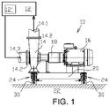
Figure 1 illustrates a pump unit coupled to a pipework aggregate according to an embodiment of the invention, -
Figure 2 illustrates a side view of the pump unit according to another embodiment of the invention, -
Figure 3 illustrates a left-side end view of theFigure 2 , -
Figure 4 illustrates a sectional view IV-IV in theFigure 2 , -
Figure 5 illustrates a sectional view V-V in theFigure 3 , -
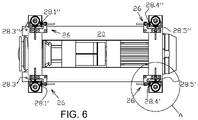
Figure 6 illustrates a sectional view VI-VI in theFigure 2 , -
Figure 7 illustrates an enlarged view A in theFigure 6 at active state, -
Figure 8 illustrates an enlarged view A in theFigure 6 at passive state, -
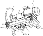
Figure 9 illustrates a side view of the pump unit according to another embodiment of the invention, -
Figure 10 illustrates a side view of the pump unit according to still another embodiment of the invention, and -
Figure 11 illustrates a side view of the pump unit according to still another embodiment of the invention. -
Figure 1 depicts schematically apump unit 10 which is coupled to a pipework, forming apipework aggregate 12. Thepump unit 10 comprises apump 14, which is here a centrifugal pump, amotor 16, and ashaft coupling 18 connecting thepump 14 and themotor 16. The pump unit further comprises abase plate 20, which is resiliently supported on afoundation 22. Thepipework aggregate 12 may be a substantially complicated network of piping which is illustrated here by theblock 12. The piping comprises straight pipes and angled part connecting the straight part as well as various appliances (valves, data collectors, mixers, etc) and processing devices 12' for processing the fluid in thepipework aggregate 12. The pipework aggregate may be for example a part of a pulp mill, water supply system, power plant or alike. - Structural dynamics of such a pipework changes from the standstill situation to operational situation. In order to cope with temperature expansion resulted in the pipework aggregate the pump unit comprises a
resilient support 24 in thebase plate 20, such that thepump unit 10 is supported resiliently on thefoundation 22. Theresilient support 24 is resilient several directions. The resilient support may comprise one of, or a combination of a spring, resilient block, such as a rubber block, vibration damper, such as viscose damper, or alike. Advantageously the resilient support is acompression spring 25. The resilient support has a main compression direction which is bearing the load caused by the mass of thepump unit 10. The main compression direction is therefore substantially vertical direction transverse to the plane or thebase plate 20. - Even if a
pump unit 10 and its resilient support is adequately designed in a view of possible vibration over the conceivable operational range (range of volume flow, pressure range, range of rotational speed) of thepump unit 10, coupling thepump unit 10 with thepipework aggregate 12 may change the vibrational characteristics and demands considerably. Structual dynamics of the pipework aggregate is difficult to define exactly beforehand. Thepump 14 is connected to the pipework aggregate without any bellows, that is using simple flange joint 14.2 directly to respective feed pipe 14.1 and return pipe 14.3. Such a flange joint may be considered as a rigid coupling. At least the flange joint 14.2. is considerably stiffer than theresilient support 24. - Now turning to
figures 2 - 8 the features and operation of the invention are explained in more detailed manner.Figure 2 shows a side view of apump unit 10 according to an embodiment of the invention. There are sectional views IV-IV and VI-VI marked in thefigure 2 which are shown in theFigure 4 andFigure 6 , respectively.Figure 3 shows a left-side end view of theFigure 2 . There is a sectional view V-V marked in thefigure 3 which is in turn shown in theFigure 5 . - The
pump unit 10 comprises anassembly 26 for attenuation of vibration of a pump unit to selectably effect on theresilient support 24 in thebase plate 20 and vibration characteristics of thepump unit 10. Theassembly 26 comprises adjustable retainer means 28 for increasing stiffness and/or damping of support of the base plate of the pump unit on the foundation. The retainer means 28 can be selectably activated for effecting on the stiffness and/or damping of support of the base plate and deactivated. In addition to mere on-off action of being activate or passive, the stiffness is adjustable by adjusting the force by which the retainer means 28 effects. - In the
Figure 7 there is shown an enlarged view A in thefigure 6 , which shows one of theresilient supports 24 in connection with which two retainer means 28 are arranged. Each one of the retainer means 28, which are referred also as stoppers, effects in one direction in the plane of thebase plate 20. And, as it can be seen for example in theFigure 6 there is a first pair of retainer means 28.1'-28.1" which effect in opposite directions to each other, in longitudinal direction of the pump unit, and a second pair of retainer means 28.3' - 28.3" which effect in opposite directions to each other, perpendicularly to the longitudinal direction of the pump unit. In other words, according to the invention the retainer means 28 are arranged as pairs in which the retainer means 28.1'-28.1" effect in opposite directions to each other. - The longitudinal direction of the pump unit is parallel to the shaft of the pump and the motor. The first pair and the second pair of retainer means are arranged at a first end of the pump unit. There is a third pair of retainer means 28.4'-28.4" which effect in opposite directions to each other, in longitudinal direction of the pump unit, and a fourth pair of retainer means 28.5' - 28.5" which effect in opposite directions to each other, perpendicularly to the longitudinal direction of the pump unit. The third pair and the fourth pair of retainer means are arranged at a second end of the
pump unit 10. The direction in the which the retainer means effect is transverse to the compression direction of the resilient support. - Should the direction of the problematic vibration i.e. selected direction, be different than the longitudinal direction of the
pump unit 10, the first pair of retainer means 28.1'-28.1" is arranged to effect in the direction of the selected direction, and a second pair of retainer means 28.3' - 28.3" is arranged to effect in the direction perpendicularly to the selected direction. - As it becomes clear particularly from the
Figure 1 thebase plate 20 is supported on thefoundation 22 by severalvertical legs 30 wherein theresilient support 24 is arranged between theleg 30 and thebase plate 20. As is shown in thefigures 2 - 8 the retainer means 28 are arranged to selectably suppress relative movement between theleg 30 and thebase plate 20 in the plane of thebase plate 20. Since the leg is attached to thefoundation 22 the movement ofbase plate 20 is suppressed considerably. - The retainer means 28 are provided with a
body part 32, and apusher part 34 adjustably attached to thebody part 32, wherein the relative movement between theleg 30 and thebase plate 20 is suppressible by bringing thepusher part 34 against either one of thebase plate 20 or theleg 32 while thebody part 32 being attached to either one of thebase plate 20 or theleg 32. In other words, while the body part is attached to one of thebase plate 20 or theleg 32, thepusher part 34 is brought against the other one of thebase plate 20 or theleg 32. In the embodiment shown in the figures, thebody part 32 of the retainer means 28 is attached by screws to thebase plate 20 and thepusher part 34 is brought against a surface of theleg 32. The pusher part is configured to adjustably push against the leg. More precisely the pusher part is configured to be selectably activated, by bring it against theleg 32, and deactivated by detaching thepusher part 34 from theleg 32, and when activated the pressing force of the pusher part is adjustable. Thepusher part 34 comprises a screw bar and the body part comprises a threadedhole 36 to which the screw bar is attached so as to provide adjustable longitudinal movement of the screw bar by rotation thereof. Thepusher part 34 is provided with aresilient head 38 at an end of thescrew bar 34. The surface in the leg, against which the pushedpart 34 is pushing can be provided with an optional,additional counter part 40, by means of the characteristics of the support can be further controlled. Thecounter part 40 may be for a resilient block or a plate. Thecounter part 40 may be arranged in connection with one or more, or all of thepusher parts 34. - The assembly is advantageously used for practising a method of operating a
pipework aggregate 12 for transporting process fluid which comprises fluid processing devices 12' and at least onepump unit 10. When the process fluid flow in the pipework aggregate is in a transient state operation, such as a start-up of the pipework aggregate, stiffness and/or damping of support of thepump unit 10 on the foundation is ruled by the resilient support solely. During the transient state vibration properties of the pipework aggregate change due to change of the fluid characteristics and the pipework aggregate, caused by the fluid processing devices. Resilient support is advantageous in this stage because during the start-up the change, or raise, of the temperature of the process fluid and/or thepipework aggregate 12 can be compensated, if not totally but still very effectively. - This state of operation is shown in the
figure 8 . As it can be seen the retainer means 28 are now adjusted to a position where thepusher parts 34 are detached from the leg, that is, not effecting on the vibration characteristics. - During the start-up process the
motor 16 of thepump unit 10 is started to run the pump and the fluid in thepipework aggregate 12 starts the transportation of the fluid in a transient state operation, during which vibration properties of the pipework aggregate may change due to change of the fluid characteristics and the pipework aggregate, caused by the fluid processing devices. In other words, during transient state operation of the process fluid flow in the pipework aggregate vibration properties of the pipework aggregate change due to change of the fluid characteristics. - After the start up, when the pipework aggregate and the process fluid flow have reached their operational temperature and being in a steady state operation, stiffness and/or damping of support of the base plate of the pump unit on the foundation is increased, such that stiffness and/or damping of support of the
pump unit 10 on the foundation is ruled in addition to the resilient support, by means of thepusher part 34, as is depicted in thefigure 7 . By means of the retainer means 28 it is possible to minimize excessive vibration of thepump unit 10 induced by excitations from the pipework. It can be said that the resilient support results in advanced operation during the start-up stage compensating heat expansion of the pipework aggregate, while during the steady state operation, when the operational temperature has been reached, increased stiffness and/or damping is brought by the pusher part minimizing excessive vibration of thepump unit 10. - Preferably in a next shut down of the pipework aggregate transient state operation is commenced after steady state operation and stiffness and/or damping of support of the base plate of the pump unit on the foundation is restored to the state of
figure 8 prevailing in the transient state. - The method may include a step of setting a target operational temperature to the process fluid and/or the pipework aggregate, and acquiring a measured temperature of the process fluid and/or the pipework aggregate, and in case the measured temperature is lower than the target operational temperature the pipework aggregate is in a transient state operation, and in case the measured temperature is equal to or higher than the target operational temperature, the pipework aggregate is in a steady state operation.
- Generally, as is depicted in the
figure 7 , when the process fluid flow is in a steady state operation stiffness and/or damping of support of the pump unit on the foundation is increased such that thepusher parts 34 are attached to, or adjusted to, be against a side wall of the leg. In the next transient state operation stiffness and/or damping of support of the base plate of the pump unit on the foundation is restored to the state prevailing in the transient state. -
Figure 9 discloses a view of apump unit 10 from beneath thepump unit 10 according to an embodiment of the invention. Thepump unit 10 comprises analternative assembly 26 for attenuation of vibration of a pump unit to selectably effect on theresilient support 24 in thebase plate 20 and vibration characteristics of thepump unit 10. Theassembly 26 comprises four retainer means 28 for increasing stiffness and/or damping of support of the base plate of the pump unit on the foundation acting in opposite and transverse direction. - Each one of the retainer means 28 effects in one direction in the plane of the
base plate 20. The assembly comprises apole 42 which is attached to thefoundation 20 similarly to thelegs 30 of thepump unit 10. In practise the surface at the end of thepole 42 in thefigure 9 is attached to the foundation. The pole extends upwardly from the foundation into the plane of thebase plate 20 between its structural beams. - The retainer means 28 are provided with a
body part 32, and apusher part 34 adjustably attached to thebody part 32, and the relative movement between thepole 42 and thebase plate 20 is suppressible by bringing thepusher part 34 against either one of thebase plate 20 or thepole 42 while thebody part 32 being attached to either one of thebase plate 20 orpole 42. In other words, while thebody part 32 is attached to one of thebase plate 20 or thepole 42, thepusher part 34 is brought against the other one of thebase plate 20 or thepole 42. In the embodiment shown in thefigure 9 thebody part 32 of the retainer means 28 is attached by welding to thebase plate 20 and thepusher part 34 is brought against a surface of thepole 42. The pusher part is configured to adjustably push against the leg. Thepusher part 34 comprises a screw bar and the body part comprises a threadedhole 36 to which the screw bar is attached so as to provide adjustable longitudinal movement of the screw bar by rotation thereof. - The assembly is advantageously used for practising a method of operating a
pipework aggregate 12 for transporting process fluid which comprises fluid processing devices 12' and at least onepump unit 10. When the process fluid flow in the pipework aggregate is in a transient state operation, such as a start-up of the pipework aggregate, stiffness and/or damping of support of thepump unit 10 on the foundation is ruled by the resilient support solely. Resilient support is advantageous in this stage because during the start-up the change, or raise, of the temperature of the process fluid and/or thepipework aggregate 12 can be compensated, if not totally but still very effectively. -
Figure 10 discloses a view of apump unit 10 from beneath according to another embodiment of the invention.View 10a shows an enlarged view of the detail a in the figure and theview 10b shows an enlarged view of the detail a seen from direction under thebase plate 20. Thepump unit 10 comprises analternative assembly 26 for attenuation of vibration of a pump unit to selectably effect on theresilient support 24 in thebase plate 20 and vibration characteristics of thepump unit 10. Theassembly 26 comprises four retainer means 28 for increasing stiffness and/or damping of support of the base plate of the pump unit on the foundation. - The retainer means 28 according to the embodiment of
figure 10 comprise asupport block 44, awedge part 46 andbody part 48 as the main components of the retainer means 28. Thesupport block 44 is attached to the lower surface of thebase plate 20 adjacent to theleg 30. Thesupport block 44 has aplanar wall 52 facing towards theleg 30. Thebody part 48 comprises a slantedside wall 54 which is facing towards theplanar wall 52. Thewedge part 46 is arranged between thebody part 48 and thesupport block 44. Thewedge part 46 has also aslanted wall 56 which is arranged against the slantedwall 54 of the body part. The retainer means 28 shown in thefigure 10 can be activated by moving thewedge part 46 sideways in respect to theplanar wall 52 of thesupport block 44. Thebody part 48 is provided with apusher screw 50 by means of which the position of thewedge part 46 can be changed. Movement of thewedge part 46 tightens the wedge-shaped space between thesupport block 44 and thebody part 48, and this way effects on the stiffness and/or damping of support of thebase plate 20. Depending on the nature of contact between theplanar wall 52 of the support block and the wall of thewedge part 46 facing theplanar wall 52 effect of the retainer means 28 can be altered. The contact may be arranged as a gliding contact by arranging a suitable glide part to either one, or both of the surface. When the contact is a gliding contact the support is practically increasing stiffness only in the direction of normal of the surface between theplanar wall 52 of the support block and the wall of thewedge part 46 facing theplanar wall 52. Without a gliding part the friction between the parts results in increasing stiffness is all directions. Instead of a separate glide part the surfaces may be arranged to have a desired co-efficient of friction. -
Figure 11 discloses a view of apump unit 10 from beneath thepump unit 10 according to another embodiment of the invention. Thepump unit 10 comprises analternative assembly 26 for attenuation of vibration of a pump unit to selectably effect on theresilient support 24 in thebase plate 20 and vibration characteristics of thepump unit 10. Theassembly 26 comprises four retainer means 28 for increasing stiffness and/or damping of support of the base plate of the pump unit on the foundation. - The retainer means 28 comprise a
bar retainer 58. The bar retainer is a straight bar which arranged to extend between twolegs 30 supporting thebase plate 20 such that theresilient support 24 is arranged between theleg 30 and thebase plate 20. The ends 60 of thebar retainer 58 may comprise adjusting screws by means of which the length of thebar retainer 58 can be adjusted. The bar retainer is attached to thebase plate 20 and itsends 60 are arranged selectably to be against thelegs 30, when the retainer means is activated, or detached from the legs, when the retainer means 28 is deactivated. There is a retainer bars arranged between eachleg 30 such that the relative movement between theleg 30 and thebase plate 20 is suppressible is two directions perpendicular to each other. The retainer bars 58 are arranged under thebase plate 20. - The embodiment shown in the
figure 11 can be further developed so that its activation and deactivation is accomplished by thermal expansion. Since the need of stiffness and/or damping of support of thepump unit 10 is advantageously dependent on the temperature of the process fluid in the pipework aggregate, it is possible to activate, or more generally control the effect of thebar retainer 58 by controlling its temperature in response to the temperature of the process fluid. In other words, thebar retainer 58 is configured to be in contact with thelegs 30 when the temperature of the process fluid is at normal operational level and detached from the legs at lower temperature than the normal operational temperature. The bar retainer means is advantageously arranged in heat transfer communication with the process fluid so as to control its heat expansion operation. - It is conceivable to practise the method such that that vibration of the
pump unit 10 is analysed during the steady state operation, and if direction of vibration, which has vibration amplitude greater than a pre-set limit value of the amplitude, is detected, stiffness and/or damping of the base plate of the pump unit is increased in at least the determined direction of vibration. This means that directions at which the retainer means effect may vary as a result of the analysis. - It is also conceivable to further develop the invention such that vibration of the pump unit is analysed during the transient state operation and if at least one direction of vibration, which has vibration amplitude greater than a pre-set limit value of the amplitude, is determined, stiffness and/or damping of the base plate of the pump unit is increased in at least the determined direction of vibration. Thus, the stiffness and/or damping of support of the base plate of the pump unit on the foundation is increased by arranging a mechanical retainer means to suppress relative movement between the base plate and the foundation in the determined direction of vibration. Change of the fluid characteristics is change of temperature and operation is steady state operation when the temperature has reached a predetermined temperature level.
- While the invention has been described herein by way of examples in connection with what are, at present, considered to be the most preferred embodiments, it is to be understood that the invention is not limited to the disclosed embodiments, but is intended to cover various combinations or modifications of its features, and several other applications included within the scope of the invention, as defined in the appended claims. The details mentioned in connection with any embodiment above may be used in connection with another embodiment when such combination is technically feasible.
Claims (15)
- A method of operating a pipework aggregate (12) comprising a pipework for transporting process fluid, fluid processing devices (12') and at least one pump unit (10), comprising a centrifugal pump (14) and a motor (16) assembled on a base plate (20), the pump unit (10) being coupled to the pipework, which pump unit (10) is supported resiliently on a foundation using a resilient support (24), which resilient support (24) is resilient in several directions, characterized by- when the process fluid flow in the pipework aggregate (12) is in a transient state operation, during which vibration properties of the pipework aggregate (12) change due to change of the fluid characteristics, stiffness and/or damping of support of the pump unit (10) on the foundation (22) is ruled by the resilient support (24), and- when the process fluid flow is in a steady state operation stiffness and/or damping of support of the pump unit (10) on the foundation (22) is increased.
- A method of operating a pipework aggregate (12) according to claim 1, characterized by- Setting a target operational temperature to the process fluid and/or the pipework aggregate (12), and acquiring a measured temperature of the process fluid and/or the pipework aggregate (12), and- in case the measured temperature is lower than the target operational temperature the pipework aggregate (12) is in a transient state operation, and- in case the measured temperature is equal to or higher than the target operational temperature, the pipework aggregate (12) is in a steady state operation, and stiffness and/or damping of support of the pump unit (10) on the foundation (22) is increased.
- A method of operating a pipework aggregate (12) according to claim 1 or 2, characterized in that during a start-up of the pipework aggregate (12)- the motor (16) is started to run the pump (14) and the fluid in the pipework aggregate (12) starts the transportation of the fluid in transient state operation, and- when the process fluid flow is in a steady state operation stiffness and/or damping of support of the base plate (20) of the pump unit (10) on the foundation is increased, and- in a next shut-down of the pipework aggregate (12) transient state operation is commenced and stiffness and/or damping of support of the base plate (20) of the pump unit (10) on the foundation (22) is restored to the state prevailing in the transient state.
- A method of operating a pipework aggregate (12) according to claim 1, characterized in that during the steady state operation, vibration of the pump unit (10) is analysed, and if direction of vibration, which has vibration amplitude greater than a pre-set limit value of the amplitude, is detected, stiffness and/or damping of the base plate (20) of the pump unit (10) is increased in at least the determined direction of vibration.
- A method of operating a pipework aggregate (12) according to anyone of the preceding claims, characterized in that stiffness and/or damping of support of the base plate (20) of the pump unit (10) on the foundation is increased by arranging a mechanical retainer means (28) to selectably suppress relative movement between the base plate (20) and the foundation in the determined direction of vibration.
- A method of operating a pipework aggregate (12) according to anyone of the preceding claims, characterized in that during the steady state operation, stiffness and/or damping of the support of the base plate (20) of the pump unit (10) is adjustably increased in a plane of the base plate (20).
- A method of operating a pipework aggregate (12) according to anyone of the preceding claims, characterized in that in a next transient state operation after a steady state operation, stiffness and/or damping of support of the base plate (20) of the pump unit (10) on the foundation is restored to the state prevailing in the transient state.
- An assembly for attenuation of vibration of a pump unit (10) coupled to a pipework aggregate (12), the pump unit (10) comprising a centrifugal pump (14) and a motor (16) assembled on a base plate (20), the pump unit (10) being supported resiliently on a foundation using a resilient support (24), which resilient support (24) is resilient several directions, characterized in that the assembly comprises a retainer means (28) configured movable between a first position suppressing relative movement between the foundation and the base plate (20) for increasing stiffness and/or damping and/or damping of support of the base plate (20) of the pump unit (10) on the foundation, a second position being neutral in influencing to relative movement between the foundation and the base plate (20).
- An assembly for attenuation of vibration of a pump unit (10) according to claims 8, characterized in that the base plate (20) is supported on the foundation by several vertical legs (30) wherein the resilient support (24) is arranged between the leg (30) and the base plate (20), and the retainer means (28) are arranged to selectably supress relative movement between the leg (30) and the base plate (20) in the plane of the base plate (20).
- An assembly for attenuation of vibration of a pump unit (10) according to anyone of the preceding claims 8-9, characterized in that the retainer means (28) are provided with a body part (32), and pusher part (34) adjustably attached to the body part (32), wherein the relative movement between the leg (30) and the base plate (20) is suppressible by bringing the pusher part (32) against either one of the base plate (20) or the leg (30) while the body part (32) being attached to either one of the base plate (20) or the leg (30).
- An assembly for attenuation of vibration of a pump unit (10) according to anyone of the preceding claims 8-10, characterized in that the body part (32) is attached to the base plate (20) and the pusher part (34) is configured to adjustably push against the leg (30).
- An assembly for attenuation of vibration of a pump unit (10) according to anyone of the preceding claims 8-11, characterized in that the pusher part (34) comprises a screw bar and the body part (32) comprises a threaded hole to which the screw bar is attached, and that the pusher part (34) is provided with a resilient head (32) at an end of the screw bar.
- An assembly for attenuation of vibration of a pump unit (10) according to anyone of the preceding claims 8-12, characterized in that the resilient support (24) are compression springs.
- An assembly for attenuation of vibration of a pump unit (10) according to anyone of the preceding claims 8-13, characterized in that the retainer means (28) are arranged as pairs in which the retainer means (28.1'-28.1") in each pair effect in opposite directions to each other.
- A pump unit (10) comprising an assembly for attenuation of vibration according to anyone of the preceding claims 8-14.
Priority Applications (2)
| Application Number | Priority Date | Filing Date | Title |
|---|---|---|---|
| FIEP21162309.5T FI4056859T3 (en) | 2021-03-12 | 2021-03-12 | A method of operating a pipework aggregate, and a pump unit comprising an assembly for attenuation of vibration of a pump unit coupled to a pipework aggregate |
| EP21162309.5A EP4056859B1 (en) | 2021-03-12 | 2021-03-12 | A method of operating a pipework aggregate, and a pump unit comprising an assembly for attenuation of vibration of a pump unit coupled to a pipework aggregate |
Applications Claiming Priority (1)
| Application Number | Priority Date | Filing Date | Title |
|---|---|---|---|
| EP21162309.5A EP4056859B1 (en) | 2021-03-12 | 2021-03-12 | A method of operating a pipework aggregate, and a pump unit comprising an assembly for attenuation of vibration of a pump unit coupled to a pipework aggregate |
Publications (2)
| Publication Number | Publication Date |
|---|---|
| EP4056859A1 true EP4056859A1 (en) | 2022-09-14 |
| EP4056859B1 EP4056859B1 (en) | 2025-01-29 |
Family
ID=74873581
Family Applications (1)
| Application Number | Title | Priority Date | Filing Date |
|---|---|---|---|
| EP21162309.5A Active EP4056859B1 (en) | 2021-03-12 | 2021-03-12 | A method of operating a pipework aggregate, and a pump unit comprising an assembly for attenuation of vibration of a pump unit coupled to a pipework aggregate |
Country Status (2)
| Country | Link |
|---|---|
| EP (1) | EP4056859B1 (en) |
| FI (1) | FI4056859T3 (en) |
Cited By (1)
| Publication number | Priority date | Publication date | Assignee | Title |
|---|---|---|---|---|
| WO2023041594A1 (en) * | 2021-09-17 | 2023-03-23 | Grundfos Holding A/S | Device and method for controlling operational vibrations of a pump or pump assembbly |
Citations (6)
| Publication number | Priority date | Publication date | Assignee | Title |
|---|---|---|---|---|
| DE29603890U1 (en) * | 1996-03-02 | 1996-05-30 | Ktr Kupplungstechnik Gmbh, 48432 Rheine | Damping ring for noise reduction with safety device |
| US20140271242A1 (en) * | 2013-03-13 | 2014-09-18 | Agilent Technologies, Inc. | Vibration/noise management in a scroll compressor |
| CN108931086A (en) * | 2018-08-22 | 2018-12-04 | 珠海格力电器股份有限公司 | Compressor vibration control method, device and unit |
| CN110500262A (en) * | 2019-09-12 | 2019-11-26 | 珠海格力电器股份有限公司 | Vibration reduction mechanism and method of fixed-frequency compressor, fixed-frequency compressor and air conditioner |
| CN111364771A (en) * | 2020-03-27 | 2020-07-03 | 上海建工一建集团有限公司 | Concrete pumping operation safety control system, arrangement method and control method thereof |
| KR20200087114A (en) | 2020-07-09 | 2020-07-20 | 주식회사 동아펌프 | Installation structure for vibration absorption and support of centrifugal pump |
Family Cites Families (1)
| Publication number | Priority date | Publication date | Assignee | Title |
|---|---|---|---|---|
| JPH06129487A (en) * | 1992-10-13 | 1994-05-10 | Hitachi Ltd | Vibration control device with variable spring constant |
-
2021
- 2021-03-12 FI FIEP21162309.5T patent/FI4056859T3/en active
- 2021-03-12 EP EP21162309.5A patent/EP4056859B1/en active Active
Patent Citations (6)
| Publication number | Priority date | Publication date | Assignee | Title |
|---|---|---|---|---|
| DE29603890U1 (en) * | 1996-03-02 | 1996-05-30 | Ktr Kupplungstechnik Gmbh, 48432 Rheine | Damping ring for noise reduction with safety device |
| US20140271242A1 (en) * | 2013-03-13 | 2014-09-18 | Agilent Technologies, Inc. | Vibration/noise management in a scroll compressor |
| CN108931086A (en) * | 2018-08-22 | 2018-12-04 | 珠海格力电器股份有限公司 | Compressor vibration control method, device and unit |
| CN110500262A (en) * | 2019-09-12 | 2019-11-26 | 珠海格力电器股份有限公司 | Vibration reduction mechanism and method of fixed-frequency compressor, fixed-frequency compressor and air conditioner |
| CN111364771A (en) * | 2020-03-27 | 2020-07-03 | 上海建工一建集团有限公司 | Concrete pumping operation safety control system, arrangement method and control method thereof |
| KR20200087114A (en) | 2020-07-09 | 2020-07-20 | 주식회사 동아펌프 | Installation structure for vibration absorption and support of centrifugal pump |
Cited By (1)
| Publication number | Priority date | Publication date | Assignee | Title |
|---|---|---|---|---|
| WO2023041594A1 (en) * | 2021-09-17 | 2023-03-23 | Grundfos Holding A/S | Device and method for controlling operational vibrations of a pump or pump assembbly |
Also Published As
| Publication number | Publication date |
|---|---|
| FI4056859T3 (en) | 2025-04-28 |
| EP4056859B1 (en) | 2025-01-29 |
Similar Documents
| Publication | Publication Date | Title |
|---|---|---|
| AU2007228927B2 (en) | Device and method for mounting a turbine engine | |
| EP2400119B1 (en) | Gas turbine engine rotor tip clearance and shaft dynamics system | |
| KR100756416B1 (en) | Piping Vibration Reduction Device | |
| CN104105847B (en) | Unit room type steam turbine and single-shaft variant combined cycle generating unit | |
| EP4056859B1 (en) | A method of operating a pipework aggregate, and a pump unit comprising an assembly for attenuation of vibration of a pump unit coupled to a pipework aggregate | |
| CN105927708B (en) | A kind of adjustable rigidity and the supporting of the active damping of damping | |
| US8616517B2 (en) | Turbomachine foot unit | |
| CN103429928A (en) | Damper having modular flexible ligaments and variable gaps | |
| Morosi et al. | Experimental investigations of active air bearings | |
| JPH0115735B2 (en) | ||
| EP0315416B1 (en) | Oscillating apparatus for damping vibration | |
| KR20130060365A (en) | Vibration damping system for a rolling mill with first and second passive hydraulic elements | |
| KR20110004252U (en) | Displacement Limit Type Vibration Isolation Spring Mount of Light Structure | |
| US20250020122A1 (en) | Device and method for controlling operational vibrations of a pump or pump assembly | |
| JPS58121336A (en) | Method of aligning shaft of machine elastically supported | |
| EP3559461B1 (en) | Passive actuator for suppressing a vibration of a column pipe of a vertical pump, vertical pump and method of retrofitting a vertical pump | |
| CN204785099U (en) | Antivibration support with tensile dish spring of buffering | |
| EP4048912B1 (en) | Bearing support and pump | |
| KR200364417Y1 (en) | A suspention device for pipe | |
| KR100349722B1 (en) | Piping Vibration Absorber | |
| JP4982272B2 (en) | Active vibration isolation mount mechanism | |
| CN114563096A (en) | Anti-seismic double-metal thermometer | |
| CN223909107U (en) | Anti-seismic bracket for heating pipeline | |
| CN1286517A (en) | Horizontal axis motor | |
| US11193503B2 (en) | Pump assembly with a vertical pump arranged in a canister |
Legal Events
| Date | Code | Title | Description |
|---|---|---|---|
| PUAI | Public reference made under article 153(3) epc to a published international application that has entered the european phase |
Free format text: ORIGINAL CODE: 0009012 |
|
| STAA | Information on the status of an ep patent application or granted ep patent |
Free format text: STATUS: THE APPLICATION HAS BEEN PUBLISHED |
|
| AK | Designated contracting states |
Kind code of ref document: A1 Designated state(s): AL AT BE BG CH CY CZ DE DK EE ES FI FR GB GR HR HU IE IS IT LI LT LU LV MC MK MT NL NO PL PT RO RS SE SI SK SM TR |
|
| STAA | Information on the status of an ep patent application or granted ep patent |
Free format text: STATUS: REQUEST FOR EXAMINATION WAS MADE |
|
| 17P | Request for examination filed |
Effective date: 20230314 |
|
| RBV | Designated contracting states (corrected) |
Designated state(s): AL AT BE BG CH CY CZ DE DK EE ES FI FR GB GR HR HU IE IS IT LI LT LU LV MC MK MT NL NO PL PT RO RS SE SI SK SM TR |
|
| RIC1 | Information provided on ipc code assigned before grant |
Ipc: F04D 29/60 20060101ALI20240710BHEP Ipc: F04D 15/00 20060101ALI20240710BHEP Ipc: F04D 29/66 20060101AFI20240710BHEP |
|
| GRAP | Despatch of communication of intention to grant a patent |
Free format text: ORIGINAL CODE: EPIDOSNIGR1 |
|
| STAA | Information on the status of an ep patent application or granted ep patent |
Free format text: STATUS: GRANT OF PATENT IS INTENDED |
|
| INTG | Intention to grant announced |
Effective date: 20240822 |
|
| GRAS | Grant fee paid |
Free format text: ORIGINAL CODE: EPIDOSNIGR3 |
|
| P01 | Opt-out of the competence of the unified patent court (upc) registered |
Free format text: CASE NUMBER: APP_61913/2024 Effective date: 20241119 |
|
| GRAA | (expected) grant |
Free format text: ORIGINAL CODE: 0009210 |
|
| STAA | Information on the status of an ep patent application or granted ep patent |
Free format text: STATUS: THE PATENT HAS BEEN GRANTED |
|
| AK | Designated contracting states |
Kind code of ref document: B1 Designated state(s): AL AT BE BG CH CY CZ DE DK EE ES FI FR GB GR HR HU IE IS IT LI LT LU LV MC MK MT NL NO PL PT RO RS SE SI SK SM TR |
|
| REG | Reference to a national code |
Ref country code: GB Ref legal event code: FG4D |
|
| REG | Reference to a national code |
Ref country code: CH Ref legal event code: EP |
|
| REG | Reference to a national code |
Ref country code: DE Ref legal event code: R096 Ref document number: 602021025283 Country of ref document: DE |
|
| REG | Reference to a national code |
Ref country code: IE Ref legal event code: FG4D |
|
| PGFP | Annual fee paid to national office [announced via postgrant information from national office to epo] |
Ref country code: AT Payment date: 20250417 Year of fee payment: 5 |
|
| REG | Reference to a national code |
Ref country code: FI Ref legal event code: FGE |
|
| REG | Reference to a national code |
Ref country code: NL Ref legal event code: MP Effective date: 20250129 |
|
| PG25 | Lapsed in a contracting state [announced via postgrant information from national office to epo] |
Ref country code: NL Free format text: LAPSE BECAUSE OF FAILURE TO SUBMIT A TRANSLATION OF THE DESCRIPTION OR TO PAY THE FEE WITHIN THE PRESCRIBED TIME-LIMIT Effective date: 20250129 |
|
| PG25 | Lapsed in a contracting state [announced via postgrant information from national office to epo] |
Ref country code: RS Free format text: LAPSE BECAUSE OF FAILURE TO SUBMIT A TRANSLATION OF THE DESCRIPTION OR TO PAY THE FEE WITHIN THE PRESCRIBED TIME-LIMIT Effective date: 20250429 |
|
| PG25 | Lapsed in a contracting state [announced via postgrant information from national office to epo] |
Ref country code: PL Free format text: LAPSE BECAUSE OF FAILURE TO SUBMIT A TRANSLATION OF THE DESCRIPTION OR TO PAY THE FEE WITHIN THE PRESCRIBED TIME-LIMIT Effective date: 20250129 |
|
| PG25 | Lapsed in a contracting state [announced via postgrant information from national office to epo] |
Ref country code: ES Free format text: LAPSE BECAUSE OF FAILURE TO SUBMIT A TRANSLATION OF THE DESCRIPTION OR TO PAY THE FEE WITHIN THE PRESCRIBED TIME-LIMIT Effective date: 20250129 |
|
| REG | Reference to a national code |
Ref country code: LT Ref legal event code: MG9D |
|
| PG25 | Lapsed in a contracting state [announced via postgrant information from national office to epo] |
Ref country code: NO Free format text: LAPSE BECAUSE OF FAILURE TO SUBMIT A TRANSLATION OF THE DESCRIPTION OR TO PAY THE FEE WITHIN THE PRESCRIBED TIME-LIMIT Effective date: 20250429 Ref country code: IS Free format text: LAPSE BECAUSE OF FAILURE TO SUBMIT A TRANSLATION OF THE DESCRIPTION OR TO PAY THE FEE WITHIN THE PRESCRIBED TIME-LIMIT Effective date: 20250529 |
|
| REG | Reference to a national code |
Ref country code: AT Ref legal event code: MK05 Ref document number: 1763690 Country of ref document: AT Kind code of ref document: T Effective date: 20250129 |
|
| PG25 | Lapsed in a contracting state [announced via postgrant information from national office to epo] |
Ref country code: HR Free format text: LAPSE BECAUSE OF FAILURE TO SUBMIT A TRANSLATION OF THE DESCRIPTION OR TO PAY THE FEE WITHIN THE PRESCRIBED TIME-LIMIT Effective date: 20250129 |
|
| PG25 | Lapsed in a contracting state [announced via postgrant information from national office to epo] |
Ref country code: LV Free format text: LAPSE BECAUSE OF FAILURE TO SUBMIT A TRANSLATION OF THE DESCRIPTION OR TO PAY THE FEE WITHIN THE PRESCRIBED TIME-LIMIT Effective date: 20250129 Ref country code: PT Free format text: LAPSE BECAUSE OF FAILURE TO SUBMIT A TRANSLATION OF THE DESCRIPTION OR TO PAY THE FEE WITHIN THE PRESCRIBED TIME-LIMIT Effective date: 20250529 |
|
| PG25 | Lapsed in a contracting state [announced via postgrant information from national office to epo] |
Ref country code: BG Free format text: LAPSE BECAUSE OF FAILURE TO SUBMIT A TRANSLATION OF THE DESCRIPTION OR TO PAY THE FEE WITHIN THE PRESCRIBED TIME-LIMIT Effective date: 20250129 Ref country code: GR Free format text: LAPSE BECAUSE OF FAILURE TO SUBMIT A TRANSLATION OF THE DESCRIPTION OR TO PAY THE FEE WITHIN THE PRESCRIBED TIME-LIMIT Effective date: 20250430 |
|
| PG25 | Lapsed in a contracting state [announced via postgrant information from national office to epo] |
Ref country code: AT Free format text: LAPSE BECAUSE OF FAILURE TO SUBMIT A TRANSLATION OF THE DESCRIPTION OR TO PAY THE FEE WITHIN THE PRESCRIBED TIME-LIMIT Effective date: 20250129 |
|
| PG25 | Lapsed in a contracting state [announced via postgrant information from national office to epo] |
Ref country code: SE Free format text: LAPSE BECAUSE OF FAILURE TO SUBMIT A TRANSLATION OF THE DESCRIPTION OR TO PAY THE FEE WITHIN THE PRESCRIBED TIME-LIMIT Effective date: 20250129 |
|
| REG | Reference to a national code |
Ref country code: DE Ref legal event code: R119 Ref document number: 602021025283 Country of ref document: DE |
|
| PG25 | Lapsed in a contracting state [announced via postgrant information from national office to epo] |
Ref country code: SM Free format text: LAPSE BECAUSE OF FAILURE TO SUBMIT A TRANSLATION OF THE DESCRIPTION OR TO PAY THE FEE WITHIN THE PRESCRIBED TIME-LIMIT Effective date: 20250129 |
|
| PG25 | Lapsed in a contracting state [announced via postgrant information from national office to epo] |
Ref country code: DK Free format text: LAPSE BECAUSE OF FAILURE TO SUBMIT A TRANSLATION OF THE DESCRIPTION OR TO PAY THE FEE WITHIN THE PRESCRIBED TIME-LIMIT Effective date: 20250129 |
|
| PG25 | Lapsed in a contracting state [announced via postgrant information from national office to epo] |
Ref country code: MC Free format text: LAPSE BECAUSE OF FAILURE TO SUBMIT A TRANSLATION OF THE DESCRIPTION OR TO PAY THE FEE WITHIN THE PRESCRIBED TIME-LIMIT Effective date: 20250129 |
|
| PG25 | Lapsed in a contracting state [announced via postgrant information from national office to epo] |
Ref country code: IT Free format text: LAPSE BECAUSE OF FAILURE TO SUBMIT A TRANSLATION OF THE DESCRIPTION OR TO PAY THE FEE WITHIN THE PRESCRIBED TIME-LIMIT Effective date: 20250129 |
|
| PG25 | Lapsed in a contracting state [announced via postgrant information from national office to epo] |
Ref country code: CZ Free format text: LAPSE BECAUSE OF FAILURE TO SUBMIT A TRANSLATION OF THE DESCRIPTION OR TO PAY THE FEE WITHIN THE PRESCRIBED TIME-LIMIT Effective date: 20250129 Ref country code: EE Free format text: LAPSE BECAUSE OF FAILURE TO SUBMIT A TRANSLATION OF THE DESCRIPTION OR TO PAY THE FEE WITHIN THE PRESCRIBED TIME-LIMIT Effective date: 20250129 |
|
| PG25 | Lapsed in a contracting state [announced via postgrant information from national office to epo] |
Ref country code: RO Free format text: LAPSE BECAUSE OF FAILURE TO SUBMIT A TRANSLATION OF THE DESCRIPTION OR TO PAY THE FEE WITHIN THE PRESCRIBED TIME-LIMIT Effective date: 20250129 |
|
| REG | Reference to a national code |
Ref country code: CH Ref legal event code: H13 Free format text: ST27 STATUS EVENT CODE: U-0-0-H10-H13 (AS PROVIDED BY THE NATIONAL OFFICE) Effective date: 20251023 |
|
| PG25 | Lapsed in a contracting state [announced via postgrant information from national office to epo] |
Ref country code: SK Free format text: LAPSE BECAUSE OF FAILURE TO SUBMIT A TRANSLATION OF THE DESCRIPTION OR TO PAY THE FEE WITHIN THE PRESCRIBED TIME-LIMIT Effective date: 20250129 |
|
| PG25 | Lapsed in a contracting state [announced via postgrant information from national office to epo] |
Ref country code: LU Free format text: LAPSE BECAUSE OF NON-PAYMENT OF DUE FEES Effective date: 20250312 |
|
| PLBE | No opposition filed within time limit |
Free format text: ORIGINAL CODE: 0009261 |
|
| STAA | Information on the status of an ep patent application or granted ep patent |
Free format text: STATUS: NO OPPOSITION FILED WITHIN TIME LIMIT |
|
| REG | Reference to a national code |
Ref country code: BE Ref legal event code: MM Effective date: 20250331 |
|
| GBPC | Gb: european patent ceased through non-payment of renewal fee |
Effective date: 20250429 |
|
| 26N | No opposition filed |
Effective date: 20251030 |
|
| PG25 | Lapsed in a contracting state [announced via postgrant information from national office to epo] |
Ref country code: DE Free format text: LAPSE BECAUSE OF NON-PAYMENT OF DUE FEES Effective date: 20251001 |
|
| PG25 | Lapsed in a contracting state [announced via postgrant information from national office to epo] |
Ref country code: GB Free format text: LAPSE BECAUSE OF NON-PAYMENT OF DUE FEES Effective date: 20250429 |
|
| PG25 | Lapsed in a contracting state [announced via postgrant information from national office to epo] |
Ref country code: FR Free format text: LAPSE BECAUSE OF NON-PAYMENT OF DUE FEES Effective date: 20250329 |
|
| PG25 | Lapsed in a contracting state [announced via postgrant information from national office to epo] |
Ref country code: BE Free format text: LAPSE BECAUSE OF NON-PAYMENT OF DUE FEES Effective date: 20250331 |
|
| PG25 | Lapsed in a contracting state [announced via postgrant information from national office to epo] |
Ref country code: CH Free format text: LAPSE BECAUSE OF NON-PAYMENT OF DUE FEES Effective date: 20250331 |
|
| PG25 | Lapsed in a contracting state [announced via postgrant information from national office to epo] |
Ref country code: IE Free format text: LAPSE BECAUSE OF NON-PAYMENT OF DUE FEES Effective date: 20250312 |
|
| PGFP | Annual fee paid to national office [announced via postgrant information from national office to epo] |
Ref country code: FI Payment date: 20260323 Year of fee payment: 6 |