EP4056828A1 - Mount assembly for accessory gearbox of aircraft engine and associated method of assembly - Google Patents
Mount assembly for accessory gearbox of aircraft engine and associated method of assembly Download PDFInfo
- Publication number
- EP4056828A1 EP4056828A1 EP22161192.4A EP22161192A EP4056828A1 EP 4056828 A1 EP4056828 A1 EP 4056828A1 EP 22161192 A EP22161192 A EP 22161192A EP 4056828 A1 EP4056828 A1 EP 4056828A1
- Authority
- EP
- European Patent Office
- Prior art keywords
- casing
- bracket
- clearance hole
- accessory gearbox
- feature
- Prior art date
- Legal status (The legal status is an assumption and is not a legal conclusion. Google has not performed a legal analysis and makes no representation as to the accuracy of the status listed.)
- Pending
Links
- 238000000034 method Methods 0.000 title claims description 13
- 230000002093 peripheral effect Effects 0.000 claims description 8
- 238000005452 bending Methods 0.000 claims description 4
- 238000010276 construction Methods 0.000 claims description 4
- 230000005489 elastic deformation Effects 0.000 claims description 3
- 238000013461 design Methods 0.000 description 8
- 230000006870 function Effects 0.000 description 7
- 239000007789 gas Substances 0.000 description 7
- 230000004807 localization Effects 0.000 description 5
- 239000000446 fuel Substances 0.000 description 4
- 239000002184 metal Substances 0.000 description 4
- 238000005516 engineering process Methods 0.000 description 3
- 238000004519 manufacturing process Methods 0.000 description 3
- 239000007858 starting material Substances 0.000 description 3
- 238000012546 transfer Methods 0.000 description 3
- 239000003570 air Substances 0.000 description 2
- 239000000567 combustion gas Substances 0.000 description 2
- 238000012986 modification Methods 0.000 description 2
- 230000004048 modification Effects 0.000 description 2
- 230000004044 response Effects 0.000 description 2
- 230000003068 static effect Effects 0.000 description 2
- 239000012080 ambient air Substances 0.000 description 1
- 230000008859 change Effects 0.000 description 1
- 238000004891 communication Methods 0.000 description 1
- 230000001419 dependent effect Effects 0.000 description 1
- 230000000694 effects Effects 0.000 description 1
- 230000006872 improvement Effects 0.000 description 1
- 238000012423 maintenance Methods 0.000 description 1
- 230000013011 mating Effects 0.000 description 1
- 230000008450 motivation Effects 0.000 description 1
- 230000036316 preload Effects 0.000 description 1
- 230000000717 retained effect Effects 0.000 description 1
- 238000012552 review Methods 0.000 description 1
- 239000007787 solid Substances 0.000 description 1
- 230000002459 sustained effect Effects 0.000 description 1
Images


Classifications
-
- F—MECHANICAL ENGINEERING; LIGHTING; HEATING; WEAPONS; BLASTING
- F02—COMBUSTION ENGINES; HOT-GAS OR COMBUSTION-PRODUCT ENGINE PLANTS
- F02C—GAS-TURBINE PLANTS; AIR INTAKES FOR JET-PROPULSION PLANTS; CONTROLLING FUEL SUPPLY IN AIR-BREATHING JET-PROPULSION PLANTS
- F02C7/00—Features, components parts, details or accessories, not provided for in, or of interest apart form groups F02C1/00 - F02C6/00; Air intakes for jet-propulsion plants
- F02C7/32—Arrangement, mounting, or driving, of auxiliaries
-
- F—MECHANICAL ENGINEERING; LIGHTING; HEATING; WEAPONS; BLASTING
- F02—COMBUSTION ENGINES; HOT-GAS OR COMBUSTION-PRODUCT ENGINE PLANTS
- F02C—GAS-TURBINE PLANTS; AIR INTAKES FOR JET-PROPULSION PLANTS; CONTROLLING FUEL SUPPLY IN AIR-BREATHING JET-PROPULSION PLANTS
- F02C7/00—Features, components parts, details or accessories, not provided for in, or of interest apart form groups F02C1/00 - F02C6/00; Air intakes for jet-propulsion plants
- F02C7/36—Power transmission arrangements between the different shafts of the gas turbine plant, or between the gas-turbine plant and the power user
-
- F—MECHANICAL ENGINEERING; LIGHTING; HEATING; WEAPONS; BLASTING
- F01—MACHINES OR ENGINES IN GENERAL; ENGINE PLANTS IN GENERAL; STEAM ENGINES
- F01D—NON-POSITIVE DISPLACEMENT MACHINES OR ENGINES, e.g. STEAM TURBINES
- F01D25/00—Component parts, details, or accessories, not provided for in, or of interest apart from, other groups
- F01D25/28—Supporting or mounting arrangements, e.g. for turbine casing
-
- F—MECHANICAL ENGINEERING; LIGHTING; HEATING; WEAPONS; BLASTING
- F05—INDEXING SCHEMES RELATING TO ENGINES OR PUMPS IN VARIOUS SUBCLASSES OF CLASSES F01-F04
- F05D—INDEXING SCHEME FOR ASPECTS RELATING TO NON-POSITIVE-DISPLACEMENT MACHINES OR ENGINES, GAS-TURBINES OR JET-PROPULSION PLANTS
- F05D2220/00—Application
- F05D2220/30—Application in turbines
- F05D2220/32—Application in turbines in gas turbines
- F05D2220/323—Application in turbines in gas turbines for aircraft propulsion, e.g. jet engines
-
- F—MECHANICAL ENGINEERING; LIGHTING; HEATING; WEAPONS; BLASTING
- F05—INDEXING SCHEMES RELATING TO ENGINES OR PUMPS IN VARIOUS SUBCLASSES OF CLASSES F01-F04
- F05D—INDEXING SCHEME FOR ASPECTS RELATING TO NON-POSITIVE-DISPLACEMENT MACHINES OR ENGINES, GAS-TURBINES OR JET-PROPULSION PLANTS
- F05D2220/00—Application
- F05D2220/50—Application for auxiliary power units (APU's)
-
- F—MECHANICAL ENGINEERING; LIGHTING; HEATING; WEAPONS; BLASTING
- F05—INDEXING SCHEMES RELATING TO ENGINES OR PUMPS IN VARIOUS SUBCLASSES OF CLASSES F01-F04
- F05D—INDEXING SCHEME FOR ASPECTS RELATING TO NON-POSITIVE-DISPLACEMENT MACHINES OR ENGINES, GAS-TURBINES OR JET-PROPULSION PLANTS
- F05D2230/00—Manufacture
- F05D2230/60—Assembly methods
-
- F—MECHANICAL ENGINEERING; LIGHTING; HEATING; WEAPONS; BLASTING
- F05—INDEXING SCHEMES RELATING TO ENGINES OR PUMPS IN VARIOUS SUBCLASSES OF CLASSES F01-F04
- F05D—INDEXING SCHEME FOR ASPECTS RELATING TO NON-POSITIVE-DISPLACEMENT MACHINES OR ENGINES, GAS-TURBINES OR JET-PROPULSION PLANTS
- F05D2240/00—Components
- F05D2240/90—Mounting on supporting structures or systems
- F05D2240/91—Mounting on supporting structures or systems on a stationary structure
-
- F—MECHANICAL ENGINEERING; LIGHTING; HEATING; WEAPONS; BLASTING
- F05—INDEXING SCHEMES RELATING TO ENGINES OR PUMPS IN VARIOUS SUBCLASSES OF CLASSES F01-F04
- F05D—INDEXING SCHEME FOR ASPECTS RELATING TO NON-POSITIVE-DISPLACEMENT MACHINES OR ENGINES, GAS-TURBINES OR JET-PROPULSION PLANTS
- F05D2260/00—Function
- F05D2260/30—Retaining components in desired mutual position
Definitions
- the application relates generally to aircraft engines and, more particularly to techniques for mounting an accessory gearbox to the aircraft casing.
- Aircraft engines typically have an accessory gearbox (AGB), sometimes alternately referred to as auxiliary gearbox or accessory drive, which can serve for exchanging power from the aircraft engine's core and "accessories".
- Accessory gearboxes typically provide for the connection to more than one accessory.
- the exact selection of accessories can vary from one engine to another, but it is relatively common for the accessories to include one or more fuel pump, oil pump, engine starter, etc, all of which can operate on the basis of power from the engine (except for the starter which rather operates to transfer power into the engine at startup).
- the accessory gearbox can be located externally from the engine's core to avoid the harsher temperatures therein, and be connected thereto by a radially-extending driveshaft.
- An AGB typically has more than one accessory port associated to different functions, and the accessory ports are connected to the driveshaft port via gearing, either directly, or via other accessory ports.
- the design of the mechanical interface between the AGB and the engine's casing is also the subject of this challenge.
- known mechanical interface schemes were satisfactory to a certain degree, there always remains room for improvement.
- an aircraft engine comprising: a casing extending along and around an axis, the casing having a first localizing feature and a shaft aperture; an accessory gearbox having a second localizing feature and a driveshaft port, the second localizing feature engaged with the first localizing feature; a driveshaft extending radially relative the axis, through the shaft aperture, the driveshaft engaged with the driveshaft port; and at least two brackets including a first bracket having a proximal end secured to the casing on a first circumferential side and a first axial side relative the first localizing feature through at least one clearance hole, and a distal end having at least one first clearance hole, the first bracket fastened to the accessory gearbox through the at least one first clearance hole, and a second bracket having a proximal end secured to the casing on the first circumferential side and a second axial side relative the first localizing feature through at least one clearance hole, and a distal end having
- a method of mounting an accessory gearbox to a casing of an aircraft engine comprising: setting the relative position and orientation between the auxiliary (or accessory) gearbox and the casing including engaging a localizing feature of the accessory (or auxiliary) gearbox with a localizing feature of the casing; and, defining a load path between the auxiliary (or accessory) gearbox and the casing, including securing at least two brackets between the previously positioned and oriented accessory gearbox and casing.
- a mount assembly for defining a load path between an accessory gearbox and a casing of an aircraft engine which are relatively positioned and oriented relative one another, the mount assembly comprising: at least two brackets each having a unibody construction, including a first bracket having a proximal end securable to the casing and a distal end having at least one first clearance hole configured for fastening the first bracket to the accessory gearbox, and a second bracket having a proximal end securable to the casing and a distal end having at least one second clearance hole configured for fastening the second bracket to the accessory gearbox.
- an aircraft engine comprising: a casing extending along and around an axis, the casing having a first localizing feature and a shaft aperture; an accessory gearbox having a second localizing feature and a driveshaft port, the second localizing feature engaged with the first localizing feature; a driveshaft extending radially relative the axis, through the shaft aperture, the driveshaft engaged with the driveshaft port, a front and a rear defined in opposite directions from the driveshaft along the axis, a left side and a right side defined in opposite directions from the driveshaft in a lateral orientation transversal to the axis; a first bracket having a proximal end secured to the casing on a first one of the left side and right side and a first one of the front and the rear, and a distal end having at least one first clearance hole, the first bracket fastened to the accessory gearbox through the at least one first clearance hole, and a second bracket having a proximal end secured to the casing on the first one
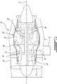
- Fig. 1 illustrates a gas turbine engine 10 of a type preferably provided for use in subsonic flight, generally comprising in serial flow communication along a main gas path a fan 12 through which ambient air is propelled, a compressor section 14 for pressurizing the air, a combustor 16 in which the compressed air is mixed with fuel and ignited for generating an annular stream of hot combustion gases around the engine axis 11, and a turbine section 18 for extracting energy from the combustion gases.
- the compressor 14, fan 12 and turbine 18 have rotating components which can be mounted on one or more shafts.
- turbofan engines for instance, to have one high pressure shaft 20, connecting a high pressure turbine section to the compressor 14, and a low pressure shaft 22, sometimes referred to as a power shaft, configured to deliver thrust.
- the low pressure shaft 22 can connect a lower pressure turbine section to the fan 12 (which can be considered a low pressure stage of the compressor).
- the design of the engine core compressor section, combustor, turbine
- the power shaft leads to blades or a propeller, respectively, located outside the casing.
- Electric and hybrid aircraft engines can also have one or more shaft associated to corresponding rotors.
- Aircraft engines have casings which can include a plurality of non-rotary components, and the exact design thereof can vary from one aircraft engine type to another.
- the casing 24 typically has a radially-inner wall 26, relative the main axis 11, forming a radially outer delimitation to the main gas path, and can also have a radially outer wall 28.
- the bypass duct 30 can be considered to form part of the casing 24, and forms a radially-outer delimitation to a bypass flow path extending around the engine core, the radially outer wall 28 forming here a radially-inner delimitation to the bypass flow path.
- Aircraft engines typically have an accessory gearbox (AGB) 32 which can serve for exchanging power from the aircraft engine's core and "accessories".
- Accessory gearboxes 32 typically provide for the connection to more than one accessory.
- the exact selection of accessories can vary from one engine to another, but it is relatively common for the accessories to include one or more fuel pump, oil pump, engine starter, etc.
- the accessory gearbox 32 can be located externally to the casing 24, and somewhat remotely from the engine's core to avoid the harsh temperatures which can be sustained during operation of the higher pressure compressors, combustor 16, and turbine sections 18.
- the accessory gearbox 32 can be connected to transfer power to an engine shaft (e.g. shaft 20) by a radially-extending driveshaft 34.
- the AGB 32 can have a housing 36 with more than one accessory ports 38a, 38c associated to different accessories, and a driveshaft port 38b.
- the accessory ports 38a, 38c are connected to the driveshaft port 38b internally to the housing 36 via gearing, either directly, or via other accessory ports, such as by a train of spur gears interconnected to each other by idler gears (not shown, known in the art).
- AGBs 32 can be relatively heavy components. Their placement, especially when remote to the engine's main axis 11, can make them prone to dynamic effects, such as resonant vibration frequency response, in addition to more typical structural considerations.
- AGBs 32 typically have complex geometries, prompting their manufacture as a component which is initially separate from the casing 24 and drive shaft 34, to which it is designed to be interfaced to.
- the design of the mechanical interface between the housing 36 and the casing 24 may thus be required to take both dynamic and static effects in consideration.
- the localizing function of the mechanical interface can be partially or fully decoupled from the load path function. More specifically, the localizing function is performed by a combination of a first localizing feature 40 which is provided as part of the casing 24, in association with a shaft aperture 42, and a second localizing feature 44 which is provided as part of the AGB 32, in association with the driveshaft port 38b.
- the first localizing feature 40 and shaft aperture 42 are better shown on Fig. 2C
- the second localizing feature 44 and driveshaft port 38b are better shown on Fig. 2B.
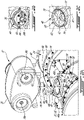
- FIG. 2A presents the AGB 32 and the casing 24 prior to engagement of the first localizing feature 40 with the second localizing feature 44, the engaged position, wherein the relative position and orientation has been set, being shown in Fig. 2D and 2E .
- the driveshaft 34 extends through the shaft aperture 42 and is engaged with the driveshaft port 38b.
- the load path function can be fully decoupled from the localizing function, and be performed by a mount assembly 46 including a plurality of brackets 48a, 48b, 48c, 48d. All the brackets 48a, 48b, 48c, 48d can be of a unibody construction, such as by being formed of a single component without any articulations therein.
- the brackets 48a, 48b, 48c, 48d can each have a first end, which can conveniently be referred to as the proximal end 50, secured to the casing 24, and a distal end 52 configured for engagement with the AGB 32.
- a body 54 of each bracket 48a, 48b, 48c, 48d extends between the proximal end 50 and the distal end 52, and the body 54 can extend to a certain extent radially 56 and circumferentially 58 relative the engine axis 11.
- brackets 48a, 48b, 48c, 48d have their proximal end 50 loosely secured to the casing 24, and the distal end 52 is left free.
- the relative orientation and position between the AGB 32 and the casing 24 is set here entirely independently from the use of the brackets 48a, 48b, 48c, 48d, and the brackets 48a, 48b, 48c, 48d can be devoid of localizing features.
- the first localizing feature 40 can have a peripheral flange 60 extending around the driveshaft axis 61, in the orientation of a length of the drive shaft 34 (radial orientation relative the main axis 11), and can have a tip 62 forming a length-wise (radial) delimitation to the peripheral flange 60.
- the second localizing feature 44 can have a male member 64 sized for snugly engaging the flange 60, and sliding lengthwisely, in the orientation of the driveshaft axis 61, (radially) along the peripheral flange 60 until the tip 62 thereof abuts against an axial seat 66.
- Figs. 2F and 2G illustrate the engagement of the first localising feature 40 with the second localizing feature 44, in accordance with one embodiment, where a seal, such as an O-ring, is provided between the flange 60 and the male member 64 to prevent any leakage therebetween.
- the flange 60 and the outer wall of the male member 64 can both have a corresponding circular cross-section and form a spigot arrangement.
- the flange 60/seat 62/male member 64 engagement can serve to set the relative position of the AGB 32 and casing 24 within the plane of the flange, i.e. a plane normal to the driveshaft axis 61, and the length of the flange 60 in the orientation of the driveshaft axis 61 can set the relative orientation of the AGB 32 and casing 24 around two orthogonal axes 70, 72 located in the plane of the flange 60.
- the engagement between the seat 66 of the male member 64 and the tip 62 can set the relative position between the AGB 32 and the casing 24 along the driveshaft axis 61.
- clocking features can additionally be provided, such as a hole 74 and bore 76 with a pin or bolt, for instance, to lock the relative orientation between the AGB 32 and the casing 24 around the driveshaft axis 61, thereby fully localizing the AGB relative to the casing 24 in all 6 degrees of freedom.
- the localizing function can be entirely played by the circular seat, which here provides for circumferential, axial, and in-plane localization.
- the relative positioning and relative orientation between the AGB 32 and the casing 24, set with the engagement between the first localizing feature 40 and the second localizing feature 44, can be the subject of a tolerance stackup which can affect the exact relative position of the free distal ends 52 of the brackets 48a, 48b, 48c, 48d relative the corresponding portions of the AGB 32.
- the distal ends 52, proximal ends 50, or both the distal ends 52 and the proximal ends 50 can be provided with one or more clearance holes 78 designed to accommodate the shafts of corresponding fasteners 80.
- both the distal ends 52 and the proximal ends 50 have clearance holes 78 having a similar design
- the proximal end 50 clearance holes 78 accommodate vertical and lateral assembly tolerances
- the distal end 52 clearance holes 78 accommodate the axial and lateral assembly tolerances.
- the clearance holes 78 of the proximal ends can be axially-oriented, whereas the clearance holes 78 of the distal ends 52 can be upwardly or radially-oriented, for instance.
- the orientation of the clearance holes 78 of the distal ends 52 and the clearance holes 78 of the proximal ends 50 can be different, ideally orthogonal to one another, to provide for adapting to assembly tolerance stackup in all orthogonal orientations.
- a degree of clearance c of a given hole 78 is defined by its difference with the diameter of the shaft of the corresponding fastener 80.
- the degree of clearance c of a given hole 78 can be defined by a difference between a radius of the hole 78 and a radius of the shaft of the corresponding fastener 80.
- clearance holes 78 will be designed larger than the shaft of the fastener 80 which they are designed to accommodate.
- the clearance hole 78 can have a greater diameter than the diameter of the shaft 80, and the clearance c can be defined as the difference between the two taken from a perfectly centered configuration.
- the clearance c can be defined as the space between the shaft 80 and (the edge of the) clearance hole 78. As varying tolerance stackups will affect the relative positioning between the clearance holes 78 and the corresponding threaded bores 82 of the AGB 32 from one manufactured engine instance to the other, the clearance c provides a corresponding degree of freedom for the corresponding fastener's shaft 80.
- the load path can be completed once the fastener heads 84 sandwich the portion of the bracket ends surrounding the corresponding clearance holes 78 against the corresponding portion of the AGB's housing 32 or case 24 either directly, or indirectly (e.g. via a washer or other element).
- the fastener heads 84 can transfer, by direct contact, any load components aligned to axis 61, while the load component aligned to axis 70 and 72 is transferred by friction force caused by fasteners preload.
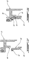
- Figs. 3A and 3B show two example positions in which the fastener shaft 80 can ultimately engage the clearance hole 78, depending on the embodiment's exact dimensions within the assembly tolerance stackup.
- Fig. 3C shows an example of a clearance hole 78' which is obround, and adapted to provide a greater degree of clearance in one orientation than in a transverse orientation.
- Such fastener and clearance hole arrangements can be used at the distal ends 52, at the proximal ends 50 or both, and are used in both the distal ends 52 and the proximal ends 50 in the embodiment illustrated in Fig. 2A .
- the brackets can be thinner in the axial orientation than in the radial 56 and circumferential 58 orientations, and remain somewhat flexible in the axial orientation while the distal ends 52 remain free. If the brackets 48a, 48b, 48c, 48d are flexible by hand before securing the distal end 52 to the AGB 32, such as by bending one or both the distal ends 52 of two axially opposite brackets 48a, 48c towards or away from the other, the designer's final selection of clearance c can factor in this flexibility.
- each one of the brackets 48a, 48b, 48c, 48d has two clearance holes 78 defined therein.
- brackets 48a, 48b, 48c, 48d can have a single clearance hole 78, or more than two clearance holes 78, to name some examples.
- the initially loosely located brackets 48a, 48b, 48c, 48d take their final, closely fitting, position only after securing via the fasteners 80, at which point the localizing features can become entirely decoupled from the load path from the point of view of rigidity and structure.
- the mount assembly 46 can have two or more brackets 48a, 48b, 48c, 48d.
- the mount assembly 46 includes four brackets 48a, 48b, 48c, 48d, a first and a second brackets 48a, 48b, being provided on a first axial side 86 (e.g.
- first and the third brackets 48a, 48c are provided on a first circumferential (or lateral) side 90 relative the driveshaft aperture 42/engaged localizing features 40, 44, and the second and the fourth brackets 48b, 48d are provided on a second circumferential side 92.
- brackets 48a, 48b, 48c, 48d once the distal ends 52 of which are fastened to the accessory gearbox 32, to entirely define the load path between the auxiliary gearbox and the casing 24, in the sense that the rigidity of the structure formed by the engagement of the localizing features 40, 44 can be insignificant, or otherwise very small compared to the rigidity of the structure formed by the fully secured brackets 48a, 48b, 48c, 48d.
- a similar objective may be achieved by using three brackets instead of four, for instance.
- the load path may be preferred for the load path to partially extend via the engaged localization features 40, 44, which can imply fastening or otherwise securing the engaged localization features, or the vicinity of the engaged localization features, to one another, and in such embodiments, it may be preferred to use only two or three brackets for instance.
- the casing 24 has a sequence of three (or more) sections 94, 96, 98 which all extend circumferentially around the main axis 11, and which all extend along the axis 11.
- These sections 94, 96, 98 include a first section 94 secured to a second section 96 at a first structural flange arrangement 95, and a third section 98 secured to the second section 96 at a second structural flange arrangement 97.
- first and second structural flange arrangement 95, 97 can include annular flanges protruding radially from a corresponding end of a corresponding section and extending circumferentially around the main axis 11. The two corresponding flanges can be secured to one another by fasteners or the like.
- the structural flange arrangements 95, 97 can provide a greater rigidity of structure than a cylindrical wall portion of the casing 24 which extends between the flange arrangements 95, 97. This additional structure can be harnessed in securing the AGB 32.
- the second section 96 is the one to which the AGB 32 is mounted, and which bears both the localizing feature 40 and the shaft aperture 42.
- brackets 48a, 48b, 48c, 48d can change from one bracket to another, and also from one embodiment to another, and can be affected by the manufacturing technique which is ultimately retained by the designer.
- the brackets 48a, 48b, 48c, 48d are made of folded sheet metal where more specifically, the distal end 52 is folded into an axially-oriented flange through which the clearance hole(s) 78 are defined.
- the proximal end 50 can extend unfolded and be sandwiched with the corresponding structural flange arrangement 95, 97 via fasteners or the like.
- it can be preferred to cast, 3D print, machine from solid, or fabricate the brackets, for instance.
- brackets 48a, 48b, 48c, 48d which extends between the proximal end 50 and the distal end 52 can extend to a significantly greater extent radially 56 and circumferentially 58 than axially 11. This can result in brackets 48a, 48b, 48c, 48d which are significantly more resistant to stresses occurring in the radial 56 or circumferential 58 orientations than to stresses occurring in the axial orientation 11, which may be suitable for some embodiments.
- the web 99 can be fastened to corresponding ones of the brackets 48a, 48b, 48c, 48d via clearance holes 78 as well, to accommodate assembly tolerance stackup along the axial orientation, for instance.
- a single web 99 was considered sufficient in the illustrated embodiment, though it will be understood that in alternate embodiments, structural webs can be used between both the first and third 48a, 48c, and second and fourth 48b, 48d brackets, or entirely omitted.
- the load path can have a footprint 91 which can be of a significantly greater surface area than the footprint of the localizing features 40, 44, which can be suitable from the point of view of addressing static and/or dynamic loads.
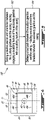
- a method 100 of mounting an accessory gearbox 32 can be represented as shown in Fig. 5 , and include a step 102 of setting the relative position and orientation between the auxiliary gearbox 32 and the casing 24 including engaging a localizing feature 44 of the accessory gearbox 32 with a localizing feature 40 of the casing 24; and a step 104 of defining a load path between the auxiliary gearbox 32 and the casing 24, including securing at least two brackets 48a, 48b, 48c, 48d between the positioned and oriented accessory gearbox 32 and the casing 24.
- defining the load path can include engaging fasteners through clearance holes 78 formed in the at least two brackets 48a, 48b, 48c, 48d, and tightening said fasteners 80 into threaded bores 82 formed in the auxiliary gearbox 32.
- Setting the relative position and orientation can include engaging a circular male feature 64 of the auxiliary gearbox 32 into a circular flange 60 of the casing until a seat 66 of the circular male feature 64 engages a tip 62 of the circular flange 60.
- This can include clocking the auxiliary gearbox 32 including rotating the male feature 64 within the circular flange 60 and locking its circumferential orientation.
- Defining the load path can further include decoupling the load path from the engaged localizing features 40, 44.
- defining the load path can include bending a distal end 52 of one or more of the brackets 48a, 48b, 48c, 48d in the axial orientation, within the elastic deformation domain.
- clearance c may not be required between the holes 78' and the shafts 80' in that or those orientations.
- a circular flange can be used to constrain both transversal and radial alignment, and an additional feature can be used to constrain circumferential rotation within the socket formed by the flange, such as a radially oriented locating hole.
- an additional feature can be used to constrain circumferential rotation within the socket formed by the flange, such as a radially oriented locating hole.
- the casing section can also be made of sheet metal, but this is optional and can be omitted in other embodiments.
- the holes can interface the major plane of the bracket at 90 degrees, and can be provided without any shims or rigging, and the brackets can be monolithic and provided without hinge joints, holes or shims.
- the locating features can be pins and mating holes instead of a flange and male member, for instance, and the male and female members can be inversed, i.e. the male feature(s) can be provided as part of the casing and the female feature(s) can be provided as part of the AGB.
- brackets can be used to secure the brackets to the AGB and/or casing in different embodiments, such as studs protruding from the AGB secured by nuts, screws, bolts, etc.
- fasteners can be used to secure the brackets to the AGB and/or casing in different embodiments, such as studs protruding from the AGB secured by nuts, screws, bolts, etc.
Landscapes
- Engineering & Computer Science (AREA)
- Chemical & Material Sciences (AREA)
- Combustion & Propulsion (AREA)
- Mechanical Engineering (AREA)
- General Engineering & Computer Science (AREA)
- Shafts, Cranks, Connecting Bars, And Related Bearings (AREA)
Abstract
Description
- The application relates generally to aircraft engines and, more particularly to techniques for mounting an accessory gearbox to the aircraft casing.
- Aircraft engines typically have an accessory gearbox (AGB), sometimes alternately referred to as auxiliary gearbox or accessory drive, which can serve for exchanging power from the aircraft engine's core and "accessories". Accessory gearboxes typically provide for the connection to more than one accessory. The exact selection of accessories can vary from one engine to another, but it is relatively common for the accessories to include one or more fuel pump, oil pump, engine starter, etc, all of which can operate on the basis of power from the engine (except for the starter which rather operates to transfer power into the engine at startup). The accessory gearbox can be located externally from the engine's core to avoid the harsher temperatures therein, and be connected thereto by a radially-extending driveshaft. An AGB typically has more than one accessory port associated to different functions, and the accessory ports are connected to the driveshaft port via gearing, either directly, or via other accessory ports.
- Aircraft engine design factors in many different considerations such as power, fuel efficiency, reliability, production costs, maintenance costs, and weight. The design of the mechanical interface between the AGB and the engine's casing is also the subject of this challenge. Although known mechanical interface schemes were satisfactory to a certain degree, there always remains room for improvement.
- In one aspect, which the Applicant expressly reserves the right to claim independently, there is provided an aircraft engine comprising: a casing extending along and around an axis, the casing having a first localizing feature and a shaft aperture; an accessory gearbox having a second localizing feature and a driveshaft port, the second localizing feature engaged with the first localizing feature; a driveshaft extending radially relative the axis, through the shaft aperture, the driveshaft engaged with the driveshaft port; and at least two brackets including a first bracket having a proximal end secured to the casing on a first circumferential side and a first axial side relative the first localizing feature through at least one clearance hole, and a distal end having at least one first clearance hole, the first bracket fastened to the accessory gearbox through the at least one first clearance hole, and a second bracket having a proximal end secured to the casing on the first circumferential side and a second axial side relative the first localizing feature through at least one clearance hole, and a distal end having at least one second clearance hole, the second bracket fastened to the accessory gearbox through the at least one second clearance hole.
- In another aspect, there is provided a method of mounting an accessory gearbox to a casing of an aircraft engine, the method comprising: setting the relative position and orientation between the auxiliary (or accessory) gearbox and the casing including engaging a localizing feature of the accessory (or auxiliary) gearbox with a localizing feature of the casing; and, defining a load path between the auxiliary (or accessory) gearbox and the casing, including securing at least two brackets between the previously positioned and oriented accessory gearbox and casing.
- In a further aspect, there is provided a mount assembly for defining a load path between an accessory gearbox and a casing of an aircraft engine which are relatively positioned and oriented relative one another, the mount assembly comprising: at least two brackets each having a unibody construction, including a first bracket having a proximal end securable to the casing and a distal end having at least one first clearance hole configured for fastening the first bracket to the accessory gearbox, and a second bracket having a proximal end securable to the casing and a distal end having at least one second clearance hole configured for fastening the second bracket to the accessory gearbox.
- In a further aspect, there is provided an aircraft engine comprising: a casing extending along and around an axis, the casing having a first localizing feature and a shaft aperture; an accessory gearbox having a second localizing feature and a driveshaft port, the second localizing feature engaged with the first localizing feature; a driveshaft extending radially relative the axis, through the shaft aperture, the driveshaft engaged with the driveshaft port, a front and a rear defined in opposite directions from the driveshaft along the axis, a left side and a right side defined in opposite directions from the driveshaft in a lateral orientation transversal to the axis; a first bracket having a proximal end secured to the casing on a first one of the left side and right side and a first one of the front and the rear, and a distal end having at least one first clearance hole, the first bracket fastened to the accessory gearbox through the at least one first clearance hole, and a second bracket having a proximal end secured to the casing on the first one of the left side and right side and a second one of the front and the rear, and a distal end having at least one second clearance hole, the second bracket fastened to the accessory gearbox through the at least one second clearance hole.
- Features of embodiments are set forth in the dependent claims.
- Reference is now made to the accompanying figures in which:
-
Fig. 1 is a schematic cross-sectional view of a gas turbine engine; -
Fig. 2A is an exploded view of an auxiliary gearbox and a receiving portion of an aircraft engine, in accordance with an embodiment; -
Figs. 2B and 2C show corresponding portions ofFig. 2A from other angles and enlarged; and -
Fig. 2D and 2E show the auxiliary gearbox ofFig. 2A assembled to the aircraft engine, from the rear and from the front, respectively; -
Fig. 2F and 2G are cross-sectional views showing the engagement between locating features; -
Fig. 3A and 3B are schematic views showing two example positions in which a fastener shaft can ultimately engage the clearance hole, depending on a given embodiment's exact dimensions within the assembly tolerance stackup; -
Fig. 3C is a schematic view showing an alternate shape of a clearance hole; -
Fig. 3D is a schematic view illustrating the clearance afforded by a clearance hole; -
Fig. 4 is a schematic top plan view of a receiving portion of the aircraft engine ofFig. 2A ; and -
Fig. 5 is a flowchart of a method of mounting an auxiliary gearbox to a gas turbine casing, in accordance with an embodiment. -
Fig. 1 illustrates agas turbine engine 10 of a type preferably provided for use in subsonic flight, generally comprising in serial flow communication along a main gas path afan 12 through which ambient air is propelled, acompressor section 14 for pressurizing the air, acombustor 16 in which the compressed air is mixed with fuel and ignited for generating an annular stream of hot combustion gases around theengine axis 11, and aturbine section 18 for extracting energy from the combustion gases. Thecompressor 14,fan 12 andturbine 18 have rotating components which can be mounted on one or more shafts. The exact design varies from one engine type to another, but it is common for turbofan engines, for instance, to have onehigh pressure shaft 20, connecting a high pressure turbine section to thecompressor 14, and alow pressure shaft 22, sometimes referred to as a power shaft, configured to deliver thrust. In the context of a turbofan engine, thelow pressure shaft 22 can connect a lower pressure turbine section to the fan 12 (which can be considered a low pressure stage of the compressor). In turboshaft and turboprop engines, to name alternate examples of gas turbine engines, the design of the engine core (compressor section, combustor, turbine) can have many similarities with the illustrated design, but the power shaft leads to blades or a propeller, respectively, located outside the casing. Electric and hybrid aircraft engines can also have one or more shaft associated to corresponding rotors. - Aircraft engines have casings which can include a plurality of non-rotary components, and the exact design thereof can vary from one aircraft engine type to another. In the case of gas turbine engines or hybrid engines, the
casing 24 typically has a radially-inner wall 26, relative themain axis 11, forming a radially outer delimitation to the main gas path, and can also have a radiallyouter wall 28. In the specific case of turbofan engines, thebypass duct 30 can be considered to form part of thecasing 24, and forms a radially-outer delimitation to a bypass flow path extending around the engine core, the radiallyouter wall 28 forming here a radially-inner delimitation to the bypass flow path. - Aircraft engines typically have an accessory gearbox (AGB) 32 which can serve for exchanging power from the aircraft engine's core and "accessories".
Accessory gearboxes 32 typically provide for the connection to more than one accessory. The exact selection of accessories can vary from one engine to another, but it is relatively common for the accessories to include one or more fuel pump, oil pump, engine starter, etc. Theaccessory gearbox 32 can be located externally to thecasing 24, and somewhat remotely from the engine's core to avoid the harsh temperatures which can be sustained during operation of the higher pressure compressors,combustor 16, andturbine sections 18. Another motivation in the selection of a location of theAGB 32 externally to the casing would be presence of available space with access to the rotor(s), this can also affect the selection of the top or bottom position relative to the casing, for instance. Theaccessory gearbox 32 can be connected to transfer power to an engine shaft (e.g. shaft 20) by a radially-extendingdriveshaft 34. As better seen in the example presented inFig. 2A , the AGB 32 can have ahousing 36 with more than oneaccessory ports driveshaft port 38b. Theaccessory ports driveshaft port 38b internally to thehousing 36 via gearing, either directly, or via other accessory ports, such as by a train of spur gears interconnected to each other by idler gears (not shown, known in the art). - Given the presence of gearing, and especially in the case of multiple ports,
AGBs 32 can be relatively heavy components. Their placement, especially when remote to the engine'smain axis 11, can make them prone to dynamic effects, such as resonant vibration frequency response, in addition to more typical structural considerations. - AGBs 32 typically have complex geometries, prompting their manufacture as a component which is initially separate from the
casing 24 anddrive shaft 34, to which it is designed to be interfaced to. The design of the mechanical interface between thehousing 36 and thecasing 24 may thus be required to take both dynamic and static effects in consideration. - Turning now to
Fig. 2A , an example embodiment of a mechanical interface between anAGB 32 and acasing 24 will now be described. It will be noted that in this embodiment, the localizing function of the mechanical interface can be partially or fully decoupled from the load path function. More specifically, the localizing function is performed by a combination of afirst localizing feature 40 which is provided as part of thecasing 24, in association with ashaft aperture 42, and asecond localizing feature 44 which is provided as part of theAGB 32, in association with thedriveshaft port 38b. Thefirst localizing feature 40 andshaft aperture 42 are better shown onFig. 2C , whereas thesecond localizing feature 44 anddriveshaft port 38b are better shown onFig. 2B. Fig. 2A presents theAGB 32 and thecasing 24 prior to engagement of thefirst localizing feature 40 with thesecond localizing feature 44, the engaged position, wherein the relative position and orientation has been set, being shown inFig. 2D and 2E . In the engaged configuration, thedriveshaft 34 extends through theshaft aperture 42 and is engaged with thedriveshaft port 38b. - In this embodiment, the load path function can be fully decoupled from the localizing function, and be performed by a
mount assembly 46 including a plurality ofbrackets brackets brackets proximal end 50, secured to thecasing 24, and adistal end 52 configured for engagement with theAGB 32. Abody 54 of eachbracket proximal end 50 and thedistal end 52, and thebody 54 can extend to a certain extent radially 56 and circumferentially 58 relative theengine axis 11. - In
Fig. 2A , thebrackets proximal end 50 loosely secured to thecasing 24, and thedistal end 52 is left free. The relative orientation and position between theAGB 32 and thecasing 24 is set here entirely independently from the use of thebrackets brackets first localizing feature 40 can have aperipheral flange 60 extending around thedriveshaft axis 61, in the orientation of a length of the drive shaft 34 (radial orientation relative the main axis 11), and can have atip 62 forming a length-wise (radial) delimitation to theperipheral flange 60. Thesecond localizing feature 44 can have amale member 64 sized for snugly engaging theflange 60, and sliding lengthwisely, in the orientation of thedriveshaft axis 61, (radially) along theperipheral flange 60 until thetip 62 thereof abuts against anaxial seat 66.Figs. 2F and 2G illustrate the engagement of thefirst localising feature 40 with thesecond localizing feature 44, in accordance with one embodiment, where a seal, such as an O-ring, is provided between theflange 60 and themale member 64 to prevent any leakage therebetween. - The
flange 60 and the outer wall of themale member 64 can both have a corresponding circular cross-section and form a spigot arrangement. Theflange 60/seat 62/male member 64 engagement can serve to set the relative position of theAGB 32 andcasing 24 within the plane of the flange, i.e. a plane normal to thedriveshaft axis 61, and the length of theflange 60 in the orientation of thedriveshaft axis 61 can set the relative orientation of theAGB 32 andcasing 24 around twoorthogonal axes flange 60. The engagement between theseat 66 of themale member 64 and thetip 62 can set the relative position between theAGB 32 and thecasing 24 along thedriveshaft axis 61. When themale member 64 can rotate relative theflange 60 around thedriveshaft axis 61, clocking features can additionally be provided, such as ahole 74 and bore 76 with a pin or bolt, for instance, to lock the relative orientation between theAGB 32 and thecasing 24 around thedriveshaft axis 61, thereby fully localizing the AGB relative to thecasing 24 in all 6 degrees of freedom. Indeed, the localizing function can be entirely played by the circular seat, which here provides for circumferential, axial, and in-plane localization. The above details are provided in association with one example only, and it will be understood that several alternate configurations are possible in alternate embodiments. - The relative positioning and relative orientation between the
AGB 32 and thecasing 24, set with the engagement between thefirst localizing feature 40 and thesecond localizing feature 44, can be the subject of a tolerance stackup which can affect the exact relative position of the free distal ends 52 of thebrackets AGB 32. To accommodate this potential assembly tolerance stackup, the distal ends 52, proximal ends 50, or both the distal ends 52 and the proximal ends 50 can be provided with one ormore clearance holes 78 designed to accommodate the shafts ofcorresponding fasteners 80. In the illustrated embodiment, both the distal ends 52 and the proximal ends 50 haveclearance holes 78 having a similar design, theproximal end 50clearance holes 78 accommodate vertical and lateral assembly tolerances and thedistal end 52clearance holes 78 accommodate the axial and lateral assembly tolerances. To this end, the clearance holes 78 of the proximal ends can be axially-oriented, whereas the clearance holes 78 of the distal ends 52 can be upwardly or radially-oriented, for instance. In other words, the orientation of the clearance holes 78 of the distal ends 52 and the clearance holes 78 of the proximal ends 50 can be different, ideally orthogonal to one another, to provide for adapting to assembly tolerance stackup in all orthogonal orientations. - A degree of clearance c of a given
hole 78 is defined by its difference with the diameter of the shaft of the correspondingfastener 80. In some embodiments, the degree of clearance c of a givenhole 78 can be defined by a difference between a radius of thehole 78 and a radius of the shaft of the correspondingfastener 80. As opposed to close tolerance, or localizing holes, which are designed with minimal play, or even interference with the shaft,clearance holes 78 will be designed larger than the shaft of thefastener 80 which they are designed to accommodate. For instance, as presented inFig. 3D , theclearance hole 78 can have a greater diameter than the diameter of theshaft 80, and the clearance c can be defined as the difference between the two taken from a perfectly centered configuration. The clearance c can be defined as the space between theshaft 80 and (the edge of the)clearance hole 78. As varying tolerance stackups will affect the relative positioning between the clearance holes 78 and the corresponding threaded bores 82 of theAGB 32 from one manufactured engine instance to the other, the clearance c provides a corresponding degree of freedom for the corresponding fastener'sshaft 80. The load path can be completed once the fastener heads 84 sandwich the portion of the bracket ends surrounding thecorresponding clearance holes 78 against the corresponding portion of the AGB'shousing 32 orcase 24 either directly, or indirectly (e.g. via a washer or other element). The fastener heads 84 can transfer, by direct contact, any load components aligned toaxis 61, while the load component aligned toaxis -
Figs. 3A and 3B show two example positions in which thefastener shaft 80 can ultimately engage theclearance hole 78, depending on the embodiment's exact dimensions within the assembly tolerance stackup.Fig. 3C shows an example of a clearance hole 78' which is obround, and adapted to provide a greater degree of clearance in one orientation than in a transverse orientation. Such fastener and clearance hole arrangements can be used at the distal ends 52, at the proximal ends 50 or both, and are used in both the distal ends 52 and the proximal ends 50 in the embodiment illustrated inFig. 2A . - The brackets can be thinner in the axial orientation than in the radial 56 and circumferential 58 orientations, and remain somewhat flexible in the axial orientation while the distal ends 52 remain free. If the
brackets distal end 52 to theAGB 32, such as by bending one or both the distal ends 52 of two axiallyopposite brackets clearance hole 78 and the threaded bore's 82 axis (which corresponds to the ultimate position of the fastener) can be accounted for by bending thebrackets Fig. 2A , each one of thebrackets clearance holes 78 defined therein. In alternate embodiments, some or all of thebrackets single clearance hole 78, or more than twoclearance holes 78, to name some examples. The initially loosely locatedbrackets fasteners 80, at which point the localizing features can become entirely decoupled from the load path from the point of view of rigidity and structure. - The embodiment presented in
Fig. 2A shows a configuration where theaccessory gearbox 32 is provided at a top of thecasing 24, as opposed to embodiments such as presented inFig. 1 where the accessory gearbox can be provided instead at a bottom of the casing. Depending on the specificities of given embodiments, themount assembly 46 can have two ormore brackets Fig. 4 , themount assembly 46 includes fourbrackets second brackets fourth brackets axial side 88. The first and thethird brackets side 90 relative thedriveshaft aperture 42/engaged localizing features 40, 44, and the second and thefourth brackets circumferential side 92. Such an arrangement can allow thebrackets accessory gearbox 32, to entirely define the load path between the auxiliary gearbox and thecasing 24, in the sense that the rigidity of the structure formed by the engagement of the localizing features 40, 44 can be insignificant, or otherwise very small compared to the rigidity of the structure formed by the fullysecured brackets - The way by which the
proximal end 50 of thebrackets casing 24 can depend on the specifics of the embodiment. In the embodiment shown inFig. 2A andFig. 4 , for instance, thecasing 24 has a sequence of three (or more)sections main axis 11, and which all extend along theaxis 11. Thesesections first section 94 secured to asecond section 96 at a firststructural flange arrangement 95, and athird section 98 secured to thesecond section 96 at a secondstructural flange arrangement 97. In alternate embodiments, one or both of the structural flange arrangements may be omitted, or formed as part of a given casing section rather than forming a connector between two casing sections, for instance. In the illustrated embodiment, the first and secondstructural flange arrangement main axis 11. The two corresponding flanges can be secured to one another by fasteners or the like. Thestructural flange arrangements casing 24 which extends between theflange arrangements AGB 32. In this example, thesecond section 96 is the one to which theAGB 32 is mounted, and which bears both the localizingfeature 40 and theshaft aperture 42. - The exact shape and configuration of the
brackets Fig. 2A , for example, thebrackets distal end 52 is folded into an axially-oriented flange through which the clearance hole(s) 78 are defined. Theproximal end 50 can extend unfolded and be sandwiched with the correspondingstructural flange arrangement Fig. 2A , thebody 54 of thebrackets proximal end 50 and thedistal end 52 can extend to a significantly greater extent radially 56 and circumferentially 58 than axially 11. This can result inbrackets axial orientation 11, which may be suitable for some embodiments. In the embodiment illustrated, it was preferred to provide astructural web 99 extending axially between two of thebrackets structural web 99 to both thesebrackets mount assembly 46 to stresses exhibited in theaxial orientation 11, especially when theweb 99 further extends to a certain extent in theradial orientation 56. It was found possible to tune the dynamic frequency response of the mountingstructure 46 in the illustrated embodiment simply by changing the thickness of the sheet metal used to form some or all of thebrackets web 99. Theweb 99 can be fastened to corresponding ones of thebrackets clearance holes 78 as well, to accommodate assembly tolerance stackup along the axial orientation, for instance. Asingle web 99 was considered sufficient in the illustrated embodiment, though it will be understood that in alternate embodiments, structural webs can be used between both the first and third 48a, 48c, and second and fourth 48b, 48d brackets, or entirely omitted. It will be noted that with the proposedmount assembly 46 configuration, the load path can have afootprint 91 which can be of a significantly greater surface area than the footprint of the localizing features 40, 44, which can be suitable from the point of view of addressing static and/or dynamic loads. - Accordingly, using a mechanical interface between the
accessory gearbox 32 and thecasing 24, including a mountingstructure 46 and localizing features 40, 44 such as presented above, amethod 100 of mounting anaccessory gearbox 32 can be represented as shown inFig. 5 , and include astep 102 of setting the relative position and orientation between theauxiliary gearbox 32 and thecasing 24 including engaging a localizingfeature 44 of theaccessory gearbox 32 with a localizingfeature 40 of thecasing 24; and astep 104 of defining a load path between theauxiliary gearbox 32 and thecasing 24, including securing at least twobrackets accessory gearbox 32 and thecasing 24. It will be noted that defining the load path can include engaging fasteners throughclearance holes 78 formed in the at least twobrackets fasteners 80 into threadedbores 82 formed in theauxiliary gearbox 32. Setting the relative position and orientation can include engaging a circularmale feature 64 of theauxiliary gearbox 32 into acircular flange 60 of the casing until aseat 66 of the circularmale feature 64 engages atip 62 of thecircular flange 60. This can include clocking theauxiliary gearbox 32 including rotating themale feature 64 within thecircular flange 60 and locking its circumferential orientation. Defining the load path can further include decoupling the load path from the engaged localizing features 40, 44. Moreover, defining the load path can include bending adistal end 52 of one or more of thebrackets - The embodiments described in this document provide non-limiting examples of possible implementations of the present technology. Upon review of the present disclosure, a person of ordinary skill in the art will recognize that changes may be made to the embodiments described herein without departing from the scope of the present technology. For example, in one embodiment, a circular flange can be used to constrain both transversal and radial alignment, and an additional feature can be used to constrain circumferential rotation within the socket formed by the flange, such as a radially oriented locating hole. These features can form a circular seat which can provide for circumferential, axial, and in-plane localization. Different configurations can be used in alternate embodiments. In one embodiment, the casing section can also be made of sheet metal, but this is optional and can be omitted in other embodiments. In some embodiments, the holes can interface the major plane of the bracket at 90 degrees, and can be provided without any shims or rigging, and the brackets can be monolithic and provided without hinge joints, holes or shims. In some alternate embodiments, the locating features can be pins and mating holes instead of a flange and male member, for instance, and the male and female members can be inversed, i.e. the male feature(s) can be provided as part of the casing and the female feature(s) can be provided as part of the AGB. Various types of fasteners can be used to secure the brackets to the AGB and/or casing in different embodiments, such as studs protruding from the AGB secured by nuts, screws, bolts, etc. Yet further modifications could be implemented by a person of ordinary skill in the art in view of the present disclosure, which modifications would be within the scope of the present technology.
Claims (15)
- An aircraft engine (10) comprising :a casing (24) extending along and around an axis (11), the casing (24) having a first localizing feature (40) and a shaft aperture (42);an accessory gearbox (32) having a second localizing feature (44) and a driveshaft port (38b), the second localizing feature (44) engaged with the first localizing feature (40);a driveshaft (34) extending radially relative the axis (11), through the shaft aperture (42), the driveshaft (34) engaged with the driveshaft port (38b), a front (86;88) and a rear (88;86) defined in opposite directions from the driveshaft (34) along the axis (11), a left side (90; 92) and a right side (92; 90) defined in opposite directions from the driveshaft (34) in a lateral orientation transversal to the axis (11);a first bracket (48a; 48b; 48c; 48d) having a proximal end (50) secured to the casing (24) on a first one of the left side and right side (90; 92) and a first one of the front and the rear (86; 88), and a distal end (52) having at least one first clearance hole (78; 78'), the first bracket (48a; 48b; 48c; 48d) fastened to the accessory gearbox (32) through the at least one first clearance hole (78; 78'), anda second bracket (48a; 48b; 48c; 48d) having a proximal end (50) secured to the casing (24) on the first one of the left side and right side (90; 92) and a second one of the front and the rear (88; 86), and a distal end (52) having at least one second clearance hole (78; 78'), the second bracket (48a; 48b; 48c; 48d) fastened to the accessory gearbox (32) through the at least one second clearance hole (78; 78').
- The aircraft engine (10) of claim 1 wherein the proximal end (50) of the first bracket (48a; 48b; 48c; 48d) has at least one third clearance hole (78; 78'), the first bracket (48a; 48b; 48c; 48d) fastened to the casing (24) through the at least one third clearance hole (78; 78'), the at least one third clearance hole (78; 78') being defined in a different orientation than the at least one first clearance hole (78; 78'), the proximal end (50) of the second bracket (48a; 48b; 48c; 48d) has at least one fourth clearance hole (78; 78'), the second bracket (48a; 48b; 48c; 48d) fastened to the casing (24) through the at least one fourth clearance hole (78; 78'), the at least one fourth clearance hole (78; 78') being defined in a different orientation than the at least one second clearance hole (78; 78').
- The aircraft engine (10) of claim 1 or 2 wherein the casing (24) has a top and a bottom defined in opposite directions from the axis (11) along a height orientation, the height orientation being transversal to the axis (11) and to the lateral orientation, the accessory gearbox (32) being at the top of the casing (24).
- The aircraft engine (10) of any preceding claim wherein the casing (24) has a sequence of at least three sections (94, 96, 98) each extending circumferentially around the axis (11) and extending along the axis (11), including a first section (94) secured to a second section (96) at a first structural flange arrangement (95), a third section (98) secured to the second section (96) at a second structural flange arrangement (97), the second section (96) having the shaft aperture (42) and first localizing feature (40), the proximal end (50) of the first bracket (48a; 48b) secured to the first structural flange arrangement (95), the proximal end (50) of the second bracket (48c; 48d) secured to the second structural flange arrangement (97).
- The aircraft engine (10) of any preceding claim, further comprising a structural web (99) extending axially between the first bracket (48b) and second bracket (48d), the structural web (99) being secured to both the first bracket (48b) and the second bracket (48d).
- The aircraft engine (10) of any preceding claim, wherein the first bracket (48a; 48b; 48c; 48d) and the second bracket (48a; 48b; 48c; 48d) each have a body (54) extending both radially and circumferentially relative the axis (11), wherein, optionally, the distal end (52) of the first bracket (48a; 48b; 48c; 48d) and the distal end (52) of the second bracket (48a; 48b; 48c; 48d ) each have a corresponding flange extending circumferentially and axially relative to the axis (11), said at least one first clearance hole (78; 78') and said at least one second clearance hole (78; 78') being defined through said corresponding flange.
- The aircraft engine (10) of any preceding claim, further comprising a third bracket (48a; 48b; 48c; 48d) having a proximal end (50) secured to the casing (24) on a second one of the left side and the right side (92; 90), and a distal end (52) having at least one third clearance hole (78; 78'), the third bracket (48a; 48b; 48c; 48d) fastened to the accessory gearbox (32) via the at least one third clearance hole (78; 78'), wherein, optionally a load path between the auxiliary gearbox (32) and the casing (24) is entirely defined via the brackets (48a; 48b; 48c; 48d).
- The aircraft engine (10) of any preceding claim, wherein the first localizing feature (40) has a peripheral flange (60) and a seat (66), the second localizing feature (44) has a male member (64) slidable along the peripheral flange (60) until it abuts against the seat (66), and the shaft aperture (42) is formed internally to a periphery of the peripheral flange (60), wherein, optionally, the peripheral flange (60) is circular in a plane transversal to an orientation of a length of the driveshaft (34), wherein the first localizing feature (40) and the second localizing feature (44) further comprise a clocking feature (74, 76) configured for setting the relative circumferential orientation of the male member (64) within the peripheral flange (60).
- The aircraft engine (10) of any preceding claim, wherein:each of the at least one first and the at least one second clearance holes (78; 78') accommodate a respective fastener (80);a clearance (c) of the at least one first clearance hole (78; 78') and of the at least one second clearance hole (78; 78') is defined relative to a size of said fasteners (78; 78'); andthe clearance (c) is sufficient to accommodate assembly tolerance stackups, optionally when taking into consideration a degree of elastic deformation ability of the brackets (48a; 48b; 48c; 48d).
- A method of mounting an accessory gearbox (32) to a casing (24) of an aircraft engine (10), the method comprising:setting the relative position and orientation between the accessory gearbox (32) and the casing (24) including engaging a localizing feature (44) of the accessory gearbox (32) with a localizing feature (40) of the casing; anddefining a load path between the accessory gearbox (32) and the casing (24), including securing at least two brackets (48a; 48b; 48c; 48d) between the previously positioned and oriented accessory gearbox (32) and casing (24).
- The method of claim 10 wherein said defining the load path includes engaging fasteners (80) through clearance holes (78; 78') formed in the at least two brackets (48a; 48b; 48c; 48d), and tightening said fasteners (80) into threaded bores (82) formed in the accessory gearbox (32).
- The method of claim 10 or 11 wherein said setting the relative position and orientation includes engaging a circular male feature (64) of the accessory gearbox (32) into a circular flange (60) of the casing (24) until a tip (62) of the circular male feature (64) engages a seat (66) of the circular flange (60), and subsequently clocking the male feature (64) including rotating it within the circular flange (60) and locking its circumferential orientation.
- The method of any of claims 10 to 12, wherein said defining the load path includes decoupling the load path from the engaged localizing features (40; 44).
- The method of any of claims 10 to 13, wherein said defining the load path includes bending a distal end (52) of two of said at least two brackets (48a; 48b; 48c; 48d) which extend axially away from one another towards one another.
- A mount assembly (46) for defining a load path between an accessory gearbox (32) and a casing (24) of an aircraft engine (10) which are relatively positioned and oriented relative one another, the mount assembly (46) comprising
at least two brackets (48a; 48b; 48c; 48d) each having a unibody construction, including:
a first bracket (48a; 48b; 48c; 48d) having a proximal end (50) securable to the casing (24) and a distal end (52) having at least one first clearance hole (78; 78') configured for fastening the first bracket to the accessory gearbox (32); and a second bracket (48a; 48b; 48c; 48d) having a proximal end (50) securable to the casing (24) and a distal end (52) having at least one second clearance hole (78; 78') configured for fastening the second bracket to the accessory gearbox (32), wherein, optionally:
the proximal end (50) of the first bracket (48a; 48b; 48c; 48d) has at least one third clearance hole (78; 78'), the first bracket (48a; 48b; 48c; 48d) fastened to the casing (24) through the at least one third clearance hole (78; 78'), the at least one third clearance hole (78; 78') being defined in a different orientation than the at least one first clearance hole (78; 78'), the proximal end (50) of the second bracket (48a; 48b; 48c; 48d) has at least one fourth clearance hole (78; 78'), the second bracket (48a; 48b; 48c; 48d) fastened to the casing (24) through the at least one fourth clearance hole (78; 78'), the at least one fourth clearance hole (78; 78') being defined in a different orientation than the at least one second clearance hole (78; 78').
Applications Claiming Priority (1)
| Application Number | Priority Date | Filing Date | Title |
|---|---|---|---|
| US17/200,292 US11674449B2 (en) | 2021-03-12 | 2021-03-12 | Mount assembly for accessory gearbox of aircraft engine and associated method of assembly |
Publications (1)
| Publication Number | Publication Date |
|---|---|
| EP4056828A1 true EP4056828A1 (en) | 2022-09-14 |
Family
ID=80685062
Family Applications (1)
| Application Number | Title | Priority Date | Filing Date |
|---|---|---|---|
| EP22161192.4A Pending EP4056828A1 (en) | 2021-03-12 | 2022-03-09 | Mount assembly for accessory gearbox of aircraft engine and associated method of assembly |
Country Status (3)
| Country | Link |
|---|---|
| US (1) | US11674449B2 (en) |
| EP (1) | EP4056828A1 (en) |
| CA (1) | CA3151889A1 (en) |
Families Citing this family (6)
| Publication number | Priority date | Publication date | Assignee | Title |
|---|---|---|---|---|
| US20240218835A1 (en) * | 2023-01-04 | 2024-07-04 | General Electric Company | Outlet guide vanes and an accessory drive gearbox for a gas turbine engine |
| US12209539B2 (en) | 2023-04-07 | 2025-01-28 | Rtx Corporation | Fusible gearbox support with catcher pin systems and methods |
| US12044181B1 (en) | 2023-04-07 | 2024-07-23 | Rtx Corporation | Fusible gearbox center guide support with catcher pin and anti-rotation pin systems and methods |
| US12196138B2 (en) | 2023-04-07 | 2025-01-14 | Rtx Corporation | Frangible gearbox center guide support systems and methods |
| US12006875B1 (en) * | 2023-04-07 | 2024-06-11 | Rtx Corporation | Fusible gearbox center guide support with frangible catcher pin systems and methods |
| US12595746B2 (en) | 2024-06-27 | 2026-04-07 | Pratt & Whitney Canada Corp. | Aircraft propulsion system with clocked electric machine and accessory gearbox |
Citations (4)
| Publication number | Priority date | Publication date | Assignee | Title |
|---|---|---|---|---|
| US2951395A (en) * | 1958-09-17 | 1960-09-06 | United Aircraft Corp | Flexible gearbox mounting |
| US3155352A (en) * | 1961-03-31 | 1964-11-03 | United Aircraft Corp | Mounting system for accessory case |
| US20170260908A1 (en) * | 2016-03-14 | 2017-09-14 | Hamilton Sundstrand Corporation | One degree-of-constraint semi-fusible gearbox mounting link |
| US10054001B2 (en) * | 2013-03-14 | 2018-08-21 | Snecma | V-shaped gearbox for driving turbomachine equipment |
Family Cites Families (11)
| Publication number | Priority date | Publication date | Assignee | Title |
|---|---|---|---|---|
| US2978869A (en) * | 1956-11-01 | 1961-04-11 | Bristol Siddeley Engines Ltd | Engine accessory mounting arrangements |
| US3543588A (en) | 1968-11-12 | 1970-12-01 | Gen Motors Corp | Accessory installation |
| US5435124A (en) * | 1994-08-10 | 1995-07-25 | United Technologies Corporation | Mounting bracket for an aircraft engine accessory |
| US6260351B1 (en) | 1998-12-10 | 2001-07-17 | United Technologies Corporation | Controlled spring rate gearbox mount |
| US8561501B2 (en) * | 2011-05-31 | 2013-10-22 | United Technologies Corporation | Gearbox mount bracket |
| US9016068B2 (en) | 2012-07-13 | 2015-04-28 | United Technologies Corporation | Mid-turbine frame with oil system mounts |
| US9500133B2 (en) | 2012-12-23 | 2016-11-22 | United Technologies Corporation | Mount with an axial upstream linkage for connecting a gearbox to a turbine engine case |
| US20160017811A1 (en) | 2013-03-08 | 2016-01-21 | United Technologies Corporation | Gearbox mounting assembly |
| US10012149B2 (en) | 2016-03-14 | 2018-07-03 | Hamilton Sundstrand Corporation | Two degree-of-constraint semi-fusible gearbox mounting link |
| US10415415B2 (en) * | 2016-07-22 | 2019-09-17 | Rolls-Royce North American Technologies Inc. | Turbine shroud with forward case and full hoop blade track |
| US20190084134A1 (en) * | 2017-09-15 | 2019-03-21 | Milwaukee Electric Tool Corporation | Tool bits and bit holders having non-circular cross-sections |
-
2021
- 2021-03-12 US US17/200,292 patent/US11674449B2/en active Active
-
2022
- 2022-03-09 EP EP22161192.4A patent/EP4056828A1/en active Pending
- 2022-03-09 CA CA3151889A patent/CA3151889A1/en active Pending
Patent Citations (4)
| Publication number | Priority date | Publication date | Assignee | Title |
|---|---|---|---|---|
| US2951395A (en) * | 1958-09-17 | 1960-09-06 | United Aircraft Corp | Flexible gearbox mounting |
| US3155352A (en) * | 1961-03-31 | 1964-11-03 | United Aircraft Corp | Mounting system for accessory case |
| US10054001B2 (en) * | 2013-03-14 | 2018-08-21 | Snecma | V-shaped gearbox for driving turbomachine equipment |
| US20170260908A1 (en) * | 2016-03-14 | 2017-09-14 | Hamilton Sundstrand Corporation | One degree-of-constraint semi-fusible gearbox mounting link |
Non-Patent Citations (1)
| Title |
|---|
| WILLIAM SHERIDAN ET AL: "Design Optimization Study of Isolation Mount Systems for Gas Turbine Engine Accessories", VOLUME 4: TURBO EXPO 2005, 1 January 2005 (2005-01-01), pages 361 - 371, XP055481238, ISBN: 978-0-7918-4727-5, DOI: 10.1115/GT2005-68048 * |
Also Published As
| Publication number | Publication date |
|---|---|
| US11674449B2 (en) | 2023-06-13 |
| CA3151889A1 (en) | 2022-09-12 |
| US20220290615A1 (en) | 2022-09-15 |
Similar Documents
| Publication | Publication Date | Title |
|---|---|---|
| US11674449B2 (en) | Mount assembly for accessory gearbox of aircraft engine and associated method of assembly | |
| US20110296847A1 (en) | Mounting assembly | |
| US9410441B2 (en) | Turboprop engine with compressor turbine shroud | |
| US20140174252A1 (en) | Mount with an axial upstream linkage for conneting a gearbox to a turbine engine case | |
| JP6472362B2 (en) | Gas turbine casing and gas turbine | |
| US11326523B2 (en) | Gas turbine engine with accessory gearbox | |
| EP4163475A1 (en) | Rotor assembly for a gas turbine engine and method for assembling same | |
| EP3992434B1 (en) | Service tube assembly for a gas turbine engine | |
| US11333078B2 (en) | Air turbine starter with decoupler | |
| EP4060164B1 (en) | Gas turbine engine and mount assembly therefor | |
| EP3246517B1 (en) | Fastener openings for stress distribution | |
| EP3561263B1 (en) | Gear assembly for coaxial shafts in gas turbine engine | |
| EP3260739A1 (en) | Low-cost epicyclic gear carrier and method of making the same | |
| EP3683148B1 (en) | Mounting apparatus for a gas turbine engine | |
| US11821330B1 (en) | Aperture pattern for gas turbine engine component with integral alignment feature | |
| JP2008519580A (en) | Electromechanical equipment | |
| US12012899B2 (en) | Auxiliary component movement restriction mounting system for gas turbine engines | |
| US12378899B2 (en) | Ducting arrangement for a gas turbine engine | |
| US12104541B1 (en) | Method and system for assembling a reduction gearbox | |
| US12215630B2 (en) | Flex coupler for hybrid gas turbine engine powerplant | |
| US20250283420A1 (en) | Joint for connection to variable guide vane of gas turbine engine | |
| EP3214277A1 (en) | Systems for stiffening cases on gas-turbine engines |
Legal Events
| Date | Code | Title | Description |
|---|---|---|---|
| PUAI | Public reference made under article 153(3) epc to a published international application that has entered the european phase |
Free format text: ORIGINAL CODE: 0009012 |
|
| STAA | Information on the status of an ep patent application or granted ep patent |
Free format text: STATUS: THE APPLICATION HAS BEEN PUBLISHED |
|
| AK | Designated contracting states |
Kind code of ref document: A1 Designated state(s): AL AT BE BG CH CY CZ DE DK EE ES FI FR GB GR HR HU IE IS IT LI LT LU LV MC MK MT NL NO PL PT RO RS SE SI SK SM TR |
|
| STAA | Information on the status of an ep patent application or granted ep patent |
Free format text: STATUS: REQUEST FOR EXAMINATION WAS MADE |
|
| 17P | Request for examination filed |
Effective date: 20230313 |
|
| RBV | Designated contracting states (corrected) |
Designated state(s): AL AT BE BG CH CY CZ DE DK EE ES FI FR GB GR HR HU IE IS IT LI LT LU LV MC MK MT NL NO PL PT RO RS SE SI SK SM TR |
|
| STAA | Information on the status of an ep patent application or granted ep patent |
Free format text: STATUS: EXAMINATION IS IN PROGRESS |
|
| 17Q | First examination report despatched |
Effective date: 20241111 |