EP4056433A1 - Slope brake pressure determining method an determining system, and vehicle - Google Patents
Slope brake pressure determining method an determining system, and vehicle Download PDFInfo
- Publication number
- EP4056433A1 EP4056433A1 EP22160732.8A EP22160732A EP4056433A1 EP 4056433 A1 EP4056433 A1 EP 4056433A1 EP 22160732 A EP22160732 A EP 22160732A EP 4056433 A1 EP4056433 A1 EP 4056433A1
- Authority
- EP
- European Patent Office
- Prior art keywords
- brake
- braking
- slope
- estimated value
- pressure
- Prior art date
- Legal status (The legal status is an assumption and is not a legal conclusion. Google has not performed a legal analysis and makes no representation as to the accuracy of the status listed.)
- Granted
Links
Images

Classifications
-
- B—PERFORMING OPERATIONS; TRANSPORTING
- B60—VEHICLES IN GENERAL
- B60T—VEHICLE BRAKE CONTROL SYSTEMS OR PARTS THEREOF; BRAKE CONTROL SYSTEMS OR PARTS THEREOF, IN GENERAL; ARRANGEMENT OF BRAKING ELEMENTS ON VEHICLES IN GENERAL; PORTABLE DEVICES FOR PREVENTING UNWANTED MOVEMENT OF VEHICLES; VEHICLE MODIFICATIONS TO FACILITATE COOLING OF BRAKES
- B60T8/00—Arrangements for adjusting wheel-braking force to meet varying vehicular or ground-surface conditions, e.g. limiting or varying distribution of braking force
- B60T8/17—Using electrical or electronic regulation means to control braking
- B60T8/172—Determining control parameters used in the regulation, e.g. by calculations involving measured or detected parameters
-
- B—PERFORMING OPERATIONS; TRANSPORTING
- B60—VEHICLES IN GENERAL
- B60T—VEHICLE BRAKE CONTROL SYSTEMS OR PARTS THEREOF; BRAKE CONTROL SYSTEMS OR PARTS THEREOF, IN GENERAL; ARRANGEMENT OF BRAKING ELEMENTS ON VEHICLES IN GENERAL; PORTABLE DEVICES FOR PREVENTING UNWANTED MOVEMENT OF VEHICLES; VEHICLE MODIFICATIONS TO FACILITATE COOLING OF BRAKES
- B60T8/00—Arrangements for adjusting wheel-braking force to meet varying vehicular or ground-surface conditions, e.g. limiting or varying distribution of braking force
- B60T8/17—Using electrical or electronic regulation means to control braking
- B60T8/171—Detecting parameters used in the regulation; Measuring values used in the regulation
-
- B—PERFORMING OPERATIONS; TRANSPORTING
- B60—VEHICLES IN GENERAL
- B60T—VEHICLE BRAKE CONTROL SYSTEMS OR PARTS THEREOF; BRAKE CONTROL SYSTEMS OR PARTS THEREOF, IN GENERAL; ARRANGEMENT OF BRAKING ELEMENTS ON VEHICLES IN GENERAL; PORTABLE DEVICES FOR PREVENTING UNWANTED MOVEMENT OF VEHICLES; VEHICLE MODIFICATIONS TO FACILITATE COOLING OF BRAKES
- B60T17/00—Component parts, details, or accessories of power brake systems not covered by groups B60T8/00, B60T13/00 or B60T15/00, or presenting other characteristic features
- B60T17/18—Safety devices; Monitoring
- B60T17/22—Devices for monitoring or checking brake systems; Signal devices
- B60T17/221—Procedure or apparatus for checking or keeping in a correct functioning condition of brake systems
-
- B—PERFORMING OPERATIONS; TRANSPORTING
- B60—VEHICLES IN GENERAL
- B60W—CONJOINT CONTROL OF VEHICLE SUB-UNITS OF DIFFERENT TYPE OR DIFFERENT FUNCTION; CONTROL SYSTEMS SPECIALLY ADAPTED FOR HYBRID VEHICLES; ROAD VEHICLE DRIVE CONTROL SYSTEMS FOR PURPOSES NOT RELATED TO THE CONTROL OF A PARTICULAR SUB-UNIT
- B60W40/00—Estimation or calculation of non-directly measurable driving parameters for road vehicle drive control systems not related to the control of a particular sub unit, e.g. by using mathematical models
- B60W40/02—Estimation or calculation of non-directly measurable driving parameters for road vehicle drive control systems not related to the control of a particular sub unit, e.g. by using mathematical models related to ambient conditions
- B60W40/06—Road conditions
- B60W40/076—Slope angle of the road
-
- B—PERFORMING OPERATIONS; TRANSPORTING
- B60—VEHICLES IN GENERAL
- B60T—VEHICLE BRAKE CONTROL SYSTEMS OR PARTS THEREOF; BRAKE CONTROL SYSTEMS OR PARTS THEREOF, IN GENERAL; ARRANGEMENT OF BRAKING ELEMENTS ON VEHICLES IN GENERAL; PORTABLE DEVICES FOR PREVENTING UNWANTED MOVEMENT OF VEHICLES; VEHICLE MODIFICATIONS TO FACILITATE COOLING OF BRAKES
- B60T2201/00—Particular use of vehicle brake systems; Special systems using also the brakes; Special software modules within the brake system controller
- B60T2201/06—Hill holder; Start aid systems on inclined road
-
- B—PERFORMING OPERATIONS; TRANSPORTING
- B60—VEHICLES IN GENERAL
- B60T—VEHICLE BRAKE CONTROL SYSTEMS OR PARTS THEREOF; BRAKE CONTROL SYSTEMS OR PARTS THEREOF, IN GENERAL; ARRANGEMENT OF BRAKING ELEMENTS ON VEHICLES IN GENERAL; PORTABLE DEVICES FOR PREVENTING UNWANTED MOVEMENT OF VEHICLES; VEHICLE MODIFICATIONS TO FACILITATE COOLING OF BRAKES
- B60T2210/00—Detection or estimation of road or environment conditions; Detection or estimation of road shapes
- B60T2210/20—Road shapes
-
- B—PERFORMING OPERATIONS; TRANSPORTING
- B60—VEHICLES IN GENERAL
- B60T—VEHICLE BRAKE CONTROL SYSTEMS OR PARTS THEREOF; BRAKE CONTROL SYSTEMS OR PARTS THEREOF, IN GENERAL; ARRANGEMENT OF BRAKING ELEMENTS ON VEHICLES IN GENERAL; PORTABLE DEVICES FOR PREVENTING UNWANTED MOVEMENT OF VEHICLES; VEHICLE MODIFICATIONS TO FACILITATE COOLING OF BRAKES
- B60T2220/00—Monitoring, detecting driver behaviour; Signalling thereof; Counteracting thereof
- B60T2220/04—Pedal travel sensor, stroke sensor; Sensing brake request
-
- B—PERFORMING OPERATIONS; TRANSPORTING
- B60—VEHICLES IN GENERAL
- B60T—VEHICLE BRAKE CONTROL SYSTEMS OR PARTS THEREOF; BRAKE CONTROL SYSTEMS OR PARTS THEREOF, IN GENERAL; ARRANGEMENT OF BRAKING ELEMENTS ON VEHICLES IN GENERAL; PORTABLE DEVICES FOR PREVENTING UNWANTED MOVEMENT OF VEHICLES; VEHICLE MODIFICATIONS TO FACILITATE COOLING OF BRAKES
- B60T2240/00—Monitoring, detecting wheel/tyre behaviour; counteracting thereof
-
- B—PERFORMING OPERATIONS; TRANSPORTING
- B60—VEHICLES IN GENERAL
- B60T—VEHICLE BRAKE CONTROL SYSTEMS OR PARTS THEREOF; BRAKE CONTROL SYSTEMS OR PARTS THEREOF, IN GENERAL; ARRANGEMENT OF BRAKING ELEMENTS ON VEHICLES IN GENERAL; PORTABLE DEVICES FOR PREVENTING UNWANTED MOVEMENT OF VEHICLES; VEHICLE MODIFICATIONS TO FACILITATE COOLING OF BRAKES
- B60T2250/00—Monitoring, detecting, estimating vehicle conditions
-
- B—PERFORMING OPERATIONS; TRANSPORTING
- B60—VEHICLES IN GENERAL
- B60T—VEHICLE BRAKE CONTROL SYSTEMS OR PARTS THEREOF; BRAKE CONTROL SYSTEMS OR PARTS THEREOF, IN GENERAL; ARRANGEMENT OF BRAKING ELEMENTS ON VEHICLES IN GENERAL; PORTABLE DEVICES FOR PREVENTING UNWANTED MOVEMENT OF VEHICLES; VEHICLE MODIFICATIONS TO FACILITATE COOLING OF BRAKES
- B60T2250/00—Monitoring, detecting, estimating vehicle conditions
- B60T2250/04—Vehicle reference speed; Vehicle body speed
-
- B—PERFORMING OPERATIONS; TRANSPORTING
- B60—VEHICLES IN GENERAL
- B60T—VEHICLE BRAKE CONTROL SYSTEMS OR PARTS THEREOF; BRAKE CONTROL SYSTEMS OR PARTS THEREOF, IN GENERAL; ARRANGEMENT OF BRAKING ELEMENTS ON VEHICLES IN GENERAL; PORTABLE DEVICES FOR PREVENTING UNWANTED MOVEMENT OF VEHICLES; VEHICLE MODIFICATIONS TO FACILITATE COOLING OF BRAKES
- B60T2270/00—Further aspects of brake control systems not otherwise provided for
- B60T2270/88—Pressure measurement in brake systems
-
- B—PERFORMING OPERATIONS; TRANSPORTING
- B60—VEHICLES IN GENERAL
- B60W—CONJOINT CONTROL OF VEHICLE SUB-UNITS OF DIFFERENT TYPE OR DIFFERENT FUNCTION; CONTROL SYSTEMS SPECIALLY ADAPTED FOR HYBRID VEHICLES; ROAD VEHICLE DRIVE CONTROL SYSTEMS FOR PURPOSES NOT RELATED TO THE CONTROL OF A PARTICULAR SUB-UNIT
- B60W2552/00—Input parameters relating to infrastructure
- B60W2552/15—Road slope, i.e. the inclination of a road segment in the longitudinal direction
Definitions
- the invention relates to vehicle control technologies, and specifically to a slope brake pressure determining method and determining system for braking on a slope.
- the commonly used algorithm is comparing a measured value of vehicle body acceleration with a calculated value of wheel speed acceleration to determine a slope, thereby calculating brake pressure.
- a problem with this method is that a vehicle body acceleration sensor fluctuates greatly when a vehicle is moving and during the starting and parking process of the vehicle, and the calculation of the wheel speed acceleration is inaccurate at low speed, which leads to unreasonable determination of the brake pressure.
- the invention is to propose a slope brake pressure determining method and a slope brake pressure determining system, so as to accurately determine brake pressure.
- a slope brake pressure determining method includes:
- the current vehicle speed is obtained from a wheel speed sensor
- the measured value of the vehicle acceleration is obtained from a vehicle body acceleration sensor and undergoes second-order filtering to obtain the slope measured value a measure .
- the pre-braking slope estimated value of the previous cycle namely the second slope estimated value a estimate2
- identifying the braking condition includes identifying according to stop and deceleration commands from a vehicle brake switch or a vehicle main controller.
- the instantaneous vehicle speed v brake is obtained from a wheel speed sensor
- the vehicle traveling distance l brake is obtained by integration on the wheel speed sensor
- the time t brake is obtained by timing
- the acceleration a brake formed by the braking force is obtained according to the following formula (6):
- the pre-braking pressure p1 is obtained based on the second slope estimated value a estimate2 , the vehicle weight, and a braking efficiency coefficient according to the following formula (7):
- Pre ⁇ braking pressure p 1 Second slope estimated value a estimate 2 * Vehicle weight * Tire radius / Braking efficiency and the pre-braking pressure p2 is obtained based on the third slope estimated value a estimate3 , the vehicle weight, and the braking efficiency coefficient according to the following formula (8):
- ⁇ braking pressure p 2 Third slope estimated value a estimate 3 * Vehicle weight * Tire radius / Braking efficiency
- a slope brake pressure determining system includes:
- the vehicle speed is obtained from a wheel speed sensor
- the measured value of the vehicle acceleration is obtained from a vehicle body acceleration sensor and undergoes second-order filtering to obtain the slope measured value a measure .
- the second slope estimated value a estimate2 of the previous cycle is latched prior to the establishment of the brake pressure, where identifying the braking condition includes identifying according to stop and deceleration commands from a vehicle brake switch or a vehicle main controller.
- the instantaneous vehicle speed v brake prior to the establishment of the brake pressure is obtained from a wheel speed sensor
- the vehicle traveling distance l brake is obtained by integration on the wheel speed sensor
- the time t brake is obtained by timing
- the pre-braking pressure p1 is obtained by calculation based on the second slope estimated value a estimate2 , the vehicle weight, and a braking efficiency coefficient according to the following formula (7):
- Pre ⁇ braking pressure p 1 Second slope estimated value a estimate 2 * Vehicle weight * Tire radius / Braking efficiency
- the pre-braking pressure p2 is obtained based on the third slope estimated value a estimate3 , the vehicle weight, and the braking efficiency coefficient according to the following formula (8):
- ⁇ braking pressure p 2 Third slope estimated value a estimate 2 * Vehicle weight * Tire radius / Braking efficiency
- a computer-readable medium has a computer program stored thereon, where when the computer program is executed by a processor, the slope brake pressure determining method of any one of claims 1 to 5 is implemented.
- a computer device includes a storage module, a processor, and a computer program stored on the storage module and capable of running on the processor, where when the computer program is executed by the processor, the foregoing slope brake pressure determining method is implemented.
- a vehicle according to an aspect of the invention includes: the foregoing slope brake pressure determining system.
- a pre-braking slope estimated value and an in-braking slope estimated value are determined for a pre-braking case and an in-braking case, respectively; then, pre-braking pressure p1 and in-braking pressure p2 are determined based on the pre-braking slope estimated value and the in-braking slope estimated value; and finally, final brake pressure p4 is obtained by calculation based on the pre-braking pressure p1 and the in-braking pressure p2. Since different physical quantities and different operating conditions are used for slope estimation, the reliability of the slope estimated value is improved.
- the following technical effects can be obtained by calculating the pre-braking pressure p1, the in-braking pressure p2, and the final brake pressure p4:
- the calculation of the pre-braking pressure ensures that the brake pressure value is not too large or too small, thereby ensuring braking comfort;
- the calculation of the brake pressure during braking dynamically adjusts the brake pressure value based on actual operation of the vehicle, thereby ensuring a braking distance;
- the calculation of the final brake pressure after braking ensures the protection against slipping of the vehicle on the slope.
- the main inventive concept of the invention lies in that, a pre-braking slope estimated value and an in-braking slope estimated value are determined for a pre-braking case and an in-braking case, respectively; then, pre-braking pressure p1 and in-braking pressure p2 are determined based on the pre-braking slope estimated value and the in-braking slope estimated value; and finally, final brake pressure p4 is obtained by calculation based on the pre-braking pressure p1 and the in-braking pressure p2. In this way, it can be ensured that the brake pressure can be accurately determined under different working conditions.
- FIG. 1 is a schematic flowchart of a slope brake pressure determining method according to an aspect of the invention.
- the slope brake pressure determining method of an aspect of the invention includes the following steps: a pre-braking slope determining step S100, an in-braking slope determining step S200, and a brake pressure determining step S300. These steps are specifically as follows:
- a pre-braking slope estimated value is determined according to a specified cycle, where vehicle acceleration a wheel is determined based on a current vehicle speed, a slope measured value a measure is obtained based on a measured value of the vehicle acceleration, and a current pre-braking slope estimated value is determined based on the vehicle acceleration a wheel and the slope measured value a measure and is used as a first slope estimated value a estimate1 , and where a pre-braking slope estimated value of a previous cycle that is latched prior to the establishment of brake pressure is used as a second slope estimated value a estimate2 .
- the first slope estimated value a estimate1 is determined according to the following formula (1): a estimate
- the slope estimated value is determined according to the specified cycle, and the second slope estimated value a estimate2 of the previous cycle is latched prior to the establishment of the brake pressure.
- the second slope estimated value a estimate2 is determined by using the same method as the first slope estimated value a estimate1 .
- the current vehicle speed is obtained from a wheel speed sensor
- the measured value of the vehicle acceleration is obtained from a vehicle body acceleration sensor and undergoes second-order filtering to obtain the slope measured value a measure .
- the second-order filtering is performed here because the acceleration sensor fluctuates greatly, and its transfer function is similar to the second-order filtering. Therefore, a more accurate value can be obtained through the second-order filtering.
- the second slope estimated value a estimate2 of the previous cycle is latched prior to the establishment of the brake pressure, where identifying the braking condition includes: identifying according to stop and deceleration commands from a vehicle brake switch or a vehicle main controller.
- identifying the braking condition includes: identifying according to stop and deceleration commands from a vehicle brake switch or a vehicle main controller.
- pre-braking pressure p1 and in-braking pressure p2 are obtained by calculation based on the second slope estimated value a estimate2 , a third slope estimated value a estimate3 , the vehicle weight, and a braking efficiency coefficient, where the third slope estimated value a estimate3 is a slope estimated value determined using an observer.
- the observer is an algorithm in the control theory, that is, to calculate a measurable value according to a theoretical formula, modify a coefficient to approximate the theoretical calculated value to an actually measured value, and indirectly estimate an unmeasurable value in the theoretical formula.
- a Luenberger observer can be used as the observer.
- a brake Brake pressure * Braking efficiency / Tire radius / Vehicle weight
- the pre-braking pressure p1 is obtained by calculation based on the second slope estimated value a estimate2 , the vehicle weight, and a braking efficiency coefficient according to the following formula (7):
- Pre-braking pressure p 1 Second slope estimated value a estimate 2 * Vehicle weight * Tire radius / Braking efficiency
- the pre-braking pressure p2 is obtained based on the third slope estimated value a estimate3 , the vehicle weight, and the braking efficiency coefficient according to the following formula (8):
- ⁇ braking pressure p 2 Third slope estimated value a estimate 3 * Vehicle weight * Tire radius / Braking efficiency
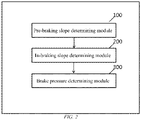
- FIG. 2 is a structural block diagram of a slope brake pressure determining system according to an aspect of the invention.
- the slope brake pressure determining system includes: a pre-braking slope determining module 100, an in-braking slope determining module 200, and a brake pressure determining module 300.
- the pre-braking slope determining module 100 is configured to determine a pre-braking slope estimated value according to a specified cycle, where vehicle acceleration a wheel is determined based on a current vehicle speed, a slope measured value a measure is obtained based on a measured value of the vehicle acceleration, and a current pre-braking slope estimated value is determined based on the vehicle acceleration a wheel and the slope measured value a measure and is used as a first slope estimated value a estimate1 , and where a pre-braking slope estimated value of a previous cycle that is latched prior to the establishment of brake pressure is used as a second slope estimated value aestimate2.
- the brake pressure determining module 300 is configured to obtain pre-braking pressure p1 and in-braking pressure p2 by calculation based on the second slope estimated value a estimate2 , the third slope estimated value a estimate3 , the vehicle weight, and a braking efficiency coefficient, where a estimate3 is a slope estimated value determined using an observer.
- the current vehicle speed is obtained from a wheel speed sensor
- the measured value of the vehicle acceleration is obtained from a vehicle body acceleration sensor and undergoes second-order filtering to obtain the slope measured value a measure .
- the second slope estimated value a estimate2 of the previous cycle is latched prior to the establishment of the brake pressure, where identifying the braking condition includes: identifying according to stop and deceleration commands from a vehicle brake switch or a vehicle main controller.
- the pre-braking pressure p1 is obtained by calculation based on the second slope estimated value a estimate2 , the vehicle weight, and a braking efficiency coefficient according to the following formula (7):
- Pre ⁇ braking pressure p 1 Second slope estimated value a estimate 2 * Vehicle weight * Tire radius / Braking efficiency
- the pre-braking pressure p2 is obtained based on the third slope estimated value a estimate3 , the vehicle weight, and the braking efficiency coefficient according to the following formula (8):
- ⁇ braking pressure p 2 Third slope estimated value a estimate 3 * Vehicle weight * Tire radius / Braking efficiency
- a pre-braking slope estimated value and an in-braking slope estimated value are determined for a pre-braking case and an in-braking case, respectively; then, pre-braking pressure p1 and in-braking pressure p2 are determined based on the pre-braking slope estimated value and the in-braking slope estimated value; and finally, final brake pressure p4 is obtained by calculation based on the pre-braking pressure p1 and the in-braking pressure p2. Since different physical quantities and different operating conditions are used for slope estimation, the reliability of the slope estimated value is improved.
- the following technical effects can be obtained by calculating the pre-braking pressure p1, the in-braking pressure p2, and the final brake pressure p4:
- the calculation of the pre-braking pressure ensures that the brake pressure value is not too large or too small, thereby ensuring braking comfort;
- the calculation of the brake pressure during braking dynamically adjusts the brake pressure value based on actual operation of the vehicle, thereby ensuring a braking distance;
- the calculation of the final brake pressure after braking ensures the protection against slipping of the vehicle on the slope.
- the invention further provides a computer-readable medium having a computer program stored thereon, where when the computer program is executed by a processor, the foregoing slope brake pressure determining method is implemented.
- the invention further provides a computer device, including a storage module, a processor, and a computer program stored on the storage module and capable of running on the processor, where when the computer program is executed by the processor, the foregoing slope brake pressure determining method is implemented.
- the invention further provides a vehicle, including the foregoing slope brake pressure determining system.
Landscapes
- Engineering & Computer Science (AREA)
- Transportation (AREA)
- Mechanical Engineering (AREA)
- Physics & Mathematics (AREA)
- Automation & Control Theory (AREA)
- Mathematical Physics (AREA)
- Regulating Braking Force (AREA)
Abstract
Description
- The invention relates to vehicle control technologies, and specifically to a slope brake pressure determining method and determining system for braking on a slope.
- In vehicle control for driver assistance, vehicle motion control needs to cover a variety of road conditions, among which slopes are the most common road conditions. The inaccurate calculation of brake pressure on a slope and brake pressure retained during parking leads to excessive braking or slipping on the slope due to insufficient braking force.
- At present, the commonly used algorithm is comparing a measured value of vehicle body acceleration with a calculated value of wheel speed acceleration to determine a slope, thereby calculating brake pressure. However, a problem with this method is that a vehicle body acceleration sensor fluctuates greatly when a vehicle is moving and during the starting and parking process of the vehicle, and the calculation of the wheel speed acceleration is inaccurate at low speed, which leads to unreasonable determination of the brake pressure.
- Therefore, it is necessary to develop a slope brake pressure algorithm to ensure accurate and reasonable determination of brake pressure under different working conditions, and to improve the driving experience of driver assistance.
- In view of the foregoing problem, the invention is to propose a slope brake pressure determining method and a slope brake pressure determining system, so as to accurately determine brake pressure.
- A slope brake pressure determining method according to an aspect of the invention includes:
- a pre-braking slope determining step, in which a pre-braking slope estimated value is determined according to a specified cycle, where vehicle acceleration awheel is determined based on a current vehicle speed, a slope measured value ameasure is obtained based on a measured value of the vehicle acceleration, and a current pre-braking slope estimated value is determined based on the vehicle acceleration awheel and the slope measured value ameasure and is used as a first slope estimated value aestimate1, and where a pre-braking slope estimated value of a previous cycle that is latched prior to the establishment of brake pressure is used as a second slope estimated value aestimate2;
- an in-braking slope determining step, in which an instantaneous vehicle speed vbrake prior to the establishment of the brake pressure is latched, a vehicle traveling distance lbrake, and time tbrake are accumulated, and an in-braking slope estimated value aslop is determined based on the instantaneous vehicle speed vbrake prior to the establishment of the brake pressure and the vehicle traveling distance lbrake, and time tbrake, where the instantaneous vehicle speed vbrake is an instantaneous vehicle speed when the brake is applied, and the vehicle traveling distance lbrake, and time tbrake are a vehicle traveling distance and time that have been accumulated from a moment at which the brake is applied; and
- a brake pressure determining step, in which pre-braking pressure p1 and in-braking pressure p2 are determined based on the second slope estimated value aestimate2 and a third slope estimated value aestimate3, respectively, initial brake pressure p3 is determined based on the pre-braking pressure p1 and the in-braking pressure p2, and final brake pressure p4 is determined based on the initial brake pressure p3, where the third slope estimated value aestimate3 is a slope estimated value determined using an observer.
- Optionally, in the pre-braking slope determining step, the first slope estimated value aestimate1 is determined according to the following formula (1):


in the brake pressure determining step, the initial brake pressure p3 is obtained according to the following formula (4):

- Optionally, in the pre-braking slope determining step, the current vehicle speed is obtained from a wheel speed sensor, and the measured value of the vehicle acceleration is obtained from a vehicle body acceleration sensor and undergoes second-order filtering to obtain the slope measured value ameasure.
- Optionally, in the pre-braking slope determining step, on the premise of identifying a braking condition, the pre-braking slope estimated value of the previous cycle, namely the second slope estimated value aestimate2, is latched prior to the establishment of the brake pressure,
where identifying the braking condition includes identifying according to stop and deceleration commands from a vehicle brake switch or a vehicle main controller. - Optionally, in the in-braking slope determining step, the instantaneous vehicle speed vbrake is obtained from a wheel speed sensor, the vehicle traveling distance lbrake, is obtained by integration on the wheel speed sensor, the time tbrake is obtained by timing, and the acceleration abrake formed by the braking force is obtained according to the following formula (6):

- Optionally, in the brake pressure determining step, the pre-braking pressure p1 is obtained based on the second slope estimated value aestimate2, the vehicle weight, and a braking efficiency coefficient according to the following formula (7):


- A slope brake pressure determining system according to an aspect of the invention includes:
- a pre-braking slope determining module, configured to determine a pre-braking slope estimated value according to a specified cycle, where vehicle acceleration awheel is determined based on a current vehicle speed, a slope measured value ameasure is obtained based on a measured value of the vehicle acceleration, and a current pre-braking slope estimated value is determined based on the vehicle acceleration awheel and the slope measured value ameasure and is used as a first slope estimated value aestimate1, and where a pre-braking slope estimated value of a previous cycle that is latched prior to the establishment of brake pressure is used as a second slope estimated value aestimate2;
- an in-braking slope determining module, configured to latch an instantaneous vehicle speed vbrake prior to the establishment of the brake pressure, accumulate a vehicle traveling distance lbrake and time tbrake, and determine an in-braking slope estimated value aslop based on the instantaneous vehicle speed vbrake prior to the establishment of the brake pressure and the vehicle traveling distance lbrake and time tbrake, where the instantaneous vehicle speed vbrake is an instantaneous vehicle speed when the brake is applied, and the vehicle traveling distance lbrake and time tbrake are a vehicle traveling distance and time that have been accumulated from a moment at which the brake is applied; and
- a brake pressure determining module, configured to determine pre-braking pressure p1 and in-braking pressure p2 based on the second slope estimated value aestimate2 and a third slope estimated value aestimate3, respectively, determine initial brake pressure p3 based on the pre-braking pressure p1 and the in-braking pressure p2, and determine final brake pressure p4 based on the initial brake pressure p3, where the third slope estimated value aestimate3 is a slope estimated value determined using an observer.
- Optionally, in the pre-braking slope determining module, the current first slope estimated value aestimate1 is determined according to the following formula (1):

in the in-braking slope determining module, the in-braking slope estimated value aslop is determined according to the following formula (2):
in the brake pressure determining module, the initial brake pressure p3 is calculated according to the following formula (4):

- Optionally, in the pre-braking slope determining module, the vehicle speed is obtained from a wheel speed sensor, and the measured value of the vehicle acceleration is obtained from a vehicle body acceleration sensor and undergoes second-order filtering to obtain the slope measured value ameasure.
- Optionally, in the pre-braking slope determining module, on the premise of identifying a braking condition, the second slope estimated value aestimate2 of the previous cycle is latched prior to the establishment of the brake pressure,
where identifying the braking condition includes identifying according to stop and deceleration commands from a vehicle brake switch or a vehicle main controller. - Optionally, in the in-braking slope determining module, the instantaneous vehicle speed vbrake prior to the establishment of the brake pressure is obtained from a wheel speed sensor, the vehicle traveling distance lbrake, is obtained by integration on the wheel speed sensor, the time tbrake is obtained by timing, and the acceleration abrake formed by the braking force is calculated according to the following formula (6):

- Optionally, in the brake pressure determining module, the pre-braking pressure p1 is obtained by calculation based on the second slope estimated value aestimate2, the vehicle weight, and a braking efficiency coefficient according to the following formula (7):


- A computer-readable medium according to an aspect of the invention has a computer program stored thereon, where when the computer program is executed by a processor, the slope brake pressure determining method of any one of claims 1 to 5 is implemented.
- A computer device according to an aspect of the invention includes a storage module, a processor, and a computer program stored on the storage module and capable of running on the processor, where when the computer program is executed by the processor, the foregoing slope brake pressure determining method is implemented.
- A vehicle according to an aspect of the invention includes: the foregoing slope brake pressure determining system.
- As described above, according to the slope brake pressure determining method and the slope brake pressure determining system of the invention, a pre-braking slope estimated value and an in-braking slope estimated value are determined for a pre-braking case and an in-braking case, respectively; then, pre-braking pressure p1 and in-braking pressure p2 are determined based on the pre-braking slope estimated value and the in-braking slope estimated value; and finally, final brake pressure p4 is obtained by calculation based on the pre-braking pressure p1 and the in-braking pressure p2. Since different physical quantities and different operating conditions are used for slope estimation, the reliability of the slope estimated value is improved.
- Moreover, the following technical effects can be obtained by calculating the pre-braking pressure p1, the in-braking pressure p2, and the final brake pressure p4: The calculation of the pre-braking pressure ensures that the brake pressure value is not too large or too small, thereby ensuring braking comfort; the calculation of the brake pressure during braking dynamically adjusts the brake pressure value based on actual operation of the vehicle, thereby ensuring a braking distance; and the calculation of the final brake pressure after braking ensures the protection against slipping of the vehicle on the slope.
-
-
FIG. 1 is a schematic flowchart of a slope brake pressure determining method according to an aspect of the invention; and -
FIG. 2 is a structural block diagram of a slope brake pressure determining system according to an aspect of the invention. - Some of the embodiments of the invention are described below and are intended to provide a basic understanding of the invention. They are not intended to confirm key or decisive elements of the invention or limit the scope of protection.
- For concise and illustrative purposes, this specification mainly describes the principles of the invention with reference to its exemplary embodiments. However, those skilled in the art will readily recognize that the same principles can be equivalently applied to all types of slope brake pressure determining methods and slope brake pressure determining systems, and the same principles can be implemented therein. Any such changes do not depart from the true spirit and scope of this patent application.
- Moreover, in the following description, reference is made to the accompanying drawings, which illustrate specific exemplary embodiments. Electrical, mechanical, logical, and structural changes can be made to these embodiments without departing from the spirit and scope of the invention. Furthermore, although the features of the invention are disclosed in combination with only one of several implementations/embodiments, if any given or recognizable function may be desired and/or advantageous, this feature can be combined with one or more other features of other implementations/embodiments. Therefore, the following description should not be considered in a limiting sense, and the scope of the invention is defined by the appended claims and their equivalents.
- The terms such as "have" and "include" indicate that in addition to the units (modules) and steps that are directly and clearly described in the specification and the claims, other units (modules) and steps that are not directly or clearly described are not excluded in the technical solutions of the invention.
- Before the description of a slope brake pressure determining method and a slope brake pressure determining system of the invention, the concept of the invention is described first.
- The main inventive concept of the invention lies in that, a pre-braking slope estimated value and an in-braking slope estimated value are determined for a pre-braking case and an in-braking case, respectively; then, pre-braking pressure p1 and in-braking pressure p2 are determined based on the pre-braking slope estimated value and the in-braking slope estimated value; and finally, final brake pressure p4 is obtained by calculation based on the pre-braking pressure p1 and the in-braking pressure p2. In this way, it can be ensured that the brake pressure can be accurately determined under different working conditions.
-
FIG. 1 is a schematic flowchart of a slope brake pressure determining method according to an aspect of the invention. - As shown in
FIG. 1 , the slope brake pressure determining method of an aspect of the invention includes the following steps: a pre-braking slope determining step S100, an in-braking slope determining step S200, and a brake pressure determining step S300. These steps are specifically as follows:
In the pre-braking slope determining step S100, a pre-braking slope estimated value is determined according to a specified cycle, where vehicle acceleration awheel is determined based on a current vehicle speed, a slope measured value ameasure is obtained based on a measured value of the vehicle acceleration, and a current pre-braking slope estimated value is determined based on the vehicle acceleration awheel and the slope measured value ameasure and is used as a first slope estimated value aestimate1, and where a pre-braking slope estimated value of a previous cycle that is latched prior to the establishment of brake pressure is used as a second slope estimated value aestimate2. In the pre-braking slope determining step S100, the first slope estimated value aestimate1 is determined according to the following formula (1):
- The slope estimated value is determined according to the specified cycle, and the second slope estimated value aestimate2 of the previous cycle is latched prior to the establishment of the brake pressure. In addition, the second slope estimated value aestimate2 is determined by using the same method as the first slope estimated value aestimate1.
- In the pre-braking slope determining step S100, the current vehicle speed is obtained from a wheel speed sensor, and the measured value of the vehicle acceleration is obtained from a vehicle body acceleration sensor and undergoes second-order filtering to obtain the slope measured value ameasure. The second-order filtering is performed here because the acceleration sensor fluctuates greatly, and its transfer function is similar to the second-order filtering. Therefore, a more accurate value can be obtained through the second-order filtering.
- In the pre-braking slope determining step S100, on the premise of identifying a braking condition, the second slope estimated value aestimate2 of the previous cycle is latched prior to the establishment of the brake pressure, where identifying the braking condition includes: identifying according to stop and deceleration commands from a vehicle brake switch or a vehicle main controller. Herein, since different physical quantities and different operating conditions are used for slope estimation, the reliability of the slope estimated value is improved.
- In the in-braking slope determining step S200, an instantaneous vehicle speed vbrake prior to the establishment of the brake pressure is latched, and a vehicle traveling distance lbrake, and time tbrake are accumulated, where the instantaneous vehicle speed vbrake is an instantaneous vehicle speed when the brake is applied, and is obtained by a wheel speed sensor, the vehicle traveling distance lbrake, is obtained by integration on the wheel speed sensor, and the time tbrake is obtained by timing, for example, timing by a controller; and an in-braking slope estimated value aslop is determined according to the following formula (2):

- In the brake pressure determining step S300, pre-braking pressure p1 and in-braking pressure p2 are obtained by calculation based on the second slope estimated value aestimate2, a third slope estimated value aestimate3, the vehicle weight, and a braking efficiency coefficient, where the third slope estimated value aestimate3 is a slope estimated value determined using an observer.
- The observer is an algorithm in the control theory, that is, to calculate a measurable value according to a theoretical formula, modify a coefficient to approximate the theoretical calculated value to an actually measured value, and indirectly estimate an unmeasurable value in the theoretical formula. Here, a Luenberger observer can be used as the observer.
- Initial brake pressure p3 is calculated according to the following formula (4):

- Final brake pressure p4 is calculated according to the following formula (5):

- In the in-braking slope determining step S200, the vehicle speed vbrake prior to the establishment of the brake pressure is obtained from the wheel speed sensor, and the acceleration abrake formed by the braking force is calculated according to the following formula (6):

- In the brake pressure determining step S300, the pre-braking pressure p1 is obtained by calculation based on the second slope estimated value aestimate2, the vehicle weight, and a braking efficiency coefficient according to the following formula (7):


-
FIG. 2 is a structural block diagram of a slope brake pressure determining system according to an aspect of the invention. - As shown in
FIG. 2 , the slope brake pressure determining system according to an aspect of the invention includes: a pre-brakingslope determining module 100, an in-brakingslope determining module 200, and a brakepressure determining module 300. The following separately describes functions implemented by the pre-brakingslope determining module 100, the in-brakingslope determining module 200, and the brakepressure determining module 300. - The pre-braking
slope determining module 100 is configured to determine a pre-braking slope estimated value according to a specified cycle, where vehicle acceleration awheel is determined based on a current vehicle speed, a slope measured value ameasure is obtained based on a measured value of the vehicle acceleration, and a current pre-braking slope estimated value is determined based on the vehicle acceleration awheel and the slope measured value ameasure and is used as a first slope estimated value aestimate1, and where a pre-braking slope estimated value of a previous cycle that is latched prior to the establishment of brake pressure is used as a second slope estimated value aestimate2. - In the pre-braking
slope determining module 100, the first slope estimated value aestimate1 is determined according to the following formula (1):
- The in-braking
slope determining module 200 is configured to latch a vehicle speed vbrake prior to the establishment of the brake pressure, and accumulate a vehicle traveling distance lbrake and time tbrake, where the instantaneous vehicle speed vbrake is an instantaneous vehicle speed when the brake is applied, and is obtained by a wheel speed sensor, the vehicle traveling distance lbrake, is obtained by integration on the wheel speed sensor, and the time tbrake is obtained by timing, for example, timing by a controller; and determine an in-braking slope estimated value aslop according to the following formula (2):
- The brake
pressure determining module 300 is configured to obtain pre-braking pressure p1 and in-braking pressure p2 by calculation based on the second slope estimated value aestimate2, the third slope estimated value aestimate3, the vehicle weight, and a braking efficiency coefficient, where aestimate3 is a slope estimated value determined using an observer. - Initial brake pressure p3 is calculated according to the following formula (4):

- Final brake pressure p4 is calculated according to the following formula (5):

- In the pre-braking
slope determining module 100, the current vehicle speed is obtained from a wheel speed sensor, and the measured value of the vehicle acceleration is obtained from a vehicle body acceleration sensor and undergoes second-order filtering to obtain the slope measured value ameasure. - In the pre-braking
slope determining module 100, on the premise of identifying a braking condition, the second slope estimated value aestimate2 of the previous cycle is latched prior to the establishment of the brake pressure, where identifying the braking condition includes: identifying according to stop and deceleration commands from a vehicle brake switch or a vehicle main controller. - In the in-braking
slope determining module 200, the vehicle speed vbrake prior to the establishment of the brake pressure is obtained from the wheel speed sensor, and the acceleration abrake formed by the braking force is calculated according to the following formula (6):
- In the brake
pressure determining module 300, the pre-braking pressure p1 is obtained by calculation based on the second slope estimated value aestimate2, the vehicle weight, and a braking efficiency coefficient according to the following formula (7):

- According to the slope brake pressure determining method and the slope brake pressure determining system of the invention, a pre-braking slope estimated value and an in-braking slope estimated value are determined for a pre-braking case and an in-braking case, respectively; then, pre-braking pressure p1 and in-braking pressure p2 are determined based on the pre-braking slope estimated value and the in-braking slope estimated value; and finally, final brake pressure p4 is obtained by calculation based on the pre-braking pressure p1 and the in-braking pressure p2. Since different physical quantities and different operating conditions are used for slope estimation, the reliability of the slope estimated value is improved.
- Moreover, the following technical effects can be obtained by calculating the pre-braking pressure p1, the in-braking pressure p2, and the final brake pressure p4: The calculation of the pre-braking pressure ensures that the brake pressure value is not too large or too small, thereby ensuring braking comfort; the calculation of the brake pressure during braking dynamically adjusts the brake pressure value based on actual operation of the vehicle, thereby ensuring a braking distance; and the calculation of the final brake pressure after braking ensures the protection against slipping of the vehicle on the slope.
- The invention further provides a computer-readable medium having a computer program stored thereon, where when the computer program is executed by a processor, the foregoing slope brake pressure determining method is implemented.
- The invention further provides a computer device, including a storage module, a processor, and a computer program stored on the storage module and capable of running on the processor, where when the computer program is executed by the processor, the foregoing slope brake pressure determining method is implemented.
- The invention further provides a vehicle, including the foregoing slope brake pressure determining system.
- The foregoing examples mainly illustrate the slope brake pressure determining method and the slope brake pressure determining system of the invention. Although only some of the specific implementations of the invention have been described, those of ordinary skill in the art should understand that the invention can be implemented in many other forms without departing from the essence and scope of the invention. Therefore, the presented examples and implementations are considered to be schematic rather than restrictive, and without departing from the spirit and scope of the invention that are defined by the appended claims, the invention may cover various changes and replacements.
Claims (13)
- A slope brake pressure determining method, comprising:a pre-braking slope determining step, in which a pre-braking slope estimated value is determined according to a specified cycle, wherein vehicle acceleration awheel is determined based on a current vehicle speed, a slope measured value ameasure is obtained based on a measured value of the vehicle acceleration, and a current pre-braking slope estimated value is determined based on the vehicle acceleration awheel and the slope measured value ameasure and is used as a first slope estimated value aestimate1, and wherein a pre-braking slope estimated value of a previous cycle that is latched prior to the establishment of brake pressure is used as a second slope estimated value aestimate2;an in-braking slope determining step, in which an instantaneous vehicle speed vbrake prior to the establishment of the brake pressure is latched, a vehicle traveling distance lbrake, and time tbrake are accumulated, and an in-braking slope estimated value aslop is determined based on the instantaneous vehicle speed vbrake prior to the establishment of the brake pressure and the vehicle traveling distance lbrake, and time tbrake, wherein the instantaneous vehicle speed vbrake is an instantaneous vehicle speed when the brake is applied, and the vehicle traveling distance lbrake, and time tbrake are a vehicle traveling distance and time that have been accumulated from a moment at which the brake is applied; anda brake pressure determining step, in which pre-braking pressure p1 and in-braking pressure p2 are determined based on the second slope estimated value aestimate2 and a third slope estimated value aestimate3, respectively, initial brake pressure p3 is determined based on the pre-braking pressure p1 and the in-braking pressure p2, and final brake pressure p4 is determined based on the initial brake pressure p3, wherein the third slope estimated value aestimate3 is a slope estimated value determined using an observer.
- The slope brake pressure determining method of claim 1, whereinin the pre-braking slope determining step, the first slope estimated value aestimate1 is determined according to the following formula (1):
 in the in-braking slope determining step, the in-braking slope estimated value aslop is determined according to the following formula (2):
 where abrake is acceleration formed by a braking force, and the acceleration abrake formed by the braking force is calculated based on brake pressure, braking efficiency, a vehicle radius, and a vehicle weight; andin the brake pressure determining step, the initial brake pressure p3 is obtained according to the following formula (4):

where Σp detal is a specified variable. - The slope brake pressure determining method of claim 1 or 2, wherein
in the pre-braking slope determining step, the current vehicle speed is obtained from a wheel speed sensor, and the measured value of the vehicle acceleration is obtained from a vehicle body acceleration sensor and undergoes second-order filtering to obtain the slope measured value ameasure. - The slope brake pressure determining method of any one of claims 1 to 3, whereinin the pre-braking slope determining step, on the premise of identifying a braking condition, the pre-braking slope estimated value of the previous cycle, namely the second slope estimated value aestimate2, is latched prior to the establishment of the brake pressure,wherein identifying the braking condition comprises identifying according to stop and deceleration commands from a vehicle brake switch or a vehicle main controller.
- The slope brake pressure determining method of any one of claims 2 to 4, wherein
in the in-braking slope determining step, the instantaneous vehicle speed vbrake is obtained from a wheel speed sensor, the vehicle traveling distance lbrake, is obtained by integration on the wheel speed sensor, the time tbrake is obtained by timing, and the acceleration abrake formed by the braking force is obtained according to the following formula (6):
- The slope brake pressure determining method of any one of claims 2 to 5, whereinin the brake pressure determining step, the pre-braking pressure p1 is obtained based on the second slope estimated value aestimate2, the vehicle weight, and a braking efficiency coefficient according to the following formula (7):
 the pre-braking pressure p2 is obtained based on the third slope estimated value aestimate3, the vehicle weight, and the braking efficiency coefficient according to the following formula (8):
- A slope brake pressure determining system, comprising:a pre-braking slope determining module, configured to determine a pre-braking slope estimated value according to a specified cycle, wherein vehicle acceleration awheel is determined based on a current vehicle speed, a slope measured value ameasure is obtained based on a measured value of the vehicle acceleration, and a current pre-braking slope estimated value is determined based on the vehicle acceleration awheel and the slope measured value ameasure and is used as a first slope estimated value aestimate1, and wherein a pre-braking slope estimated value of a previous cycle that is latched prior to the establishment of brake pressure is used as a second slope estimated value aestimate2;an in-braking slope determining module, configured to latch an instantaneous vehicle speed vbrake prior to the establishment of the brake pressure, accumulate a vehicle traveling distance lbrake and time tbrake, and determine an in-braking slope estimated value aslop based on the instantaneous vehicle speed vbrake prior to the establishment of the brake pressure and the vehicle traveling distance lbrake and time tbrake, wherein the instantaneous vehicle speed vbrake is an instantaneous vehicle speed when the brake is applied, and the vehicle traveling distance lbrake and time tbrake are a vehicle traveling distance and time that have been accumulated from a moment at which the brake is applied; anda brake pressure determining module, configured to determine pre-braking pressure p1 and in-braking pressure p2 based on the second slope estimated value aestimate2 and a third slope estimated value aestimate3, respectively, determine initial brake pressure p3 based on the pre-braking pressure p1 and the in-braking pressure p2, and determine final brake pressure p4 based on the initial brake pressure p3, wherein the third slope estimated value aestimate3 is a slope estimated value determined using an observer.
- The slope brake pressure determining system of claim 7, wherein in the pre-braking slope determining module, the current first slope estimated value aestimate1 is determined according to the following formula (1):
 wherein the slope estimated value is determined according to the specified cycle, and the second slope estimated value aestimate2 of the previous cycle is latched prior to the establishment of the brake pressure;in the in-braking slope determining module, the in-braking slope estimated value aslop is determined according to the following formula (2):
 where abrake is acceleration formed by a braking force, and the acceleration abrake formed by the braking force is calculated based on brake pressure, braking efficiency, a vehicle radius, and a vehicle weight; andin the brake pressure determining module, the initial brake pressure p3 is calculated according to the following formula (4):
 the final brake pressure p4 is calculated according to the following formula (5):
where Σp detal is a specified variable. - The slope brake pressure determining system of claim 7 or 8, wherein
in the pre-braking slope determining module, the vehicle speed is obtained from a wheel speed sensor, and the measured value of the vehicle acceleration is obtained from a vehicle body acceleration sensor and undergoes second-order filtering to obtain the slope measured value ameasure. - The slope brake pressure determining system of claim 7, 8, or 9, whereinin the pre-braking slope determining module, on the premise of identifying a braking condition, the second slope estimated value aestimate2 of the previous cycle is latched prior to the establishment of the brake pressure,wherein identifying the braking condition comprises identifying according to stop and deceleration commands from a vehicle brake switch or a vehicle main controller.
- The slope brake pressure determining system of any one of claims 8 to 10, whereinin the in-braking slope determining module, the instantaneous vehicle speed vbrake prior to the establishment of the brake pressure is obtained from a wheel speed sensor, the vehicle traveling distance lbrake is obtained by integration on the wheel speed sensor, the time tbrake is obtained by timing, and the acceleration abrake formed by the braking force is calculated according to the following formula (6):

- The slope brake pressure determining system of any one of claims 8 to 11, whereinin the brake pressure determining module, the pre-braking pressure p1 is obtained by calculation based on the second slope estimated value aestimate2, the vehicle weight, and a braking efficiency coefficient according to the following formula (7):
 the pre-braking pressure p2 is obtained based on the third slope estimated value aestimate3, the vehicle weight, and the braking efficiency coefficient according to the following formula (8):
- A vehicle, comprising: the slope brake pressure determining system of any one of claims 7 to 12.
Applications Claiming Priority (1)
| Application Number | Priority Date | Filing Date | Title |
|---|---|---|---|
| CN202110265017.XA CN112896119B (en) | 2021-03-11 | 2021-03-11 | Slope brake pressure determination method and determination system, vehicle |
Publications (2)
| Publication Number | Publication Date |
|---|---|
| EP4056433A1 true EP4056433A1 (en) | 2022-09-14 |
| EP4056433B1 EP4056433B1 (en) | 2024-09-25 |
Family
ID=76105211
Family Applications (1)
| Application Number | Title | Priority Date | Filing Date |
|---|---|---|---|
| EP22160732.8A Active EP4056433B1 (en) | 2021-03-11 | 2022-03-08 | Slope brake pressure determining method and determining system, and vehicle |
Country Status (3)
| Country | Link |
|---|---|
| US (1) | US12377826B2 (en) |
| EP (1) | EP4056433B1 (en) |
| CN (1) | CN112896119B (en) |
Cited By (1)
| Publication number | Priority date | Publication date | Assignee | Title |
|---|---|---|---|---|
| CN116373811A (en) * | 2023-04-11 | 2023-07-04 | 蔚来汽车科技(安徽)有限公司 | Vehicle automatic parking control method |
Families Citing this family (2)
| Publication number | Priority date | Publication date | Assignee | Title |
|---|---|---|---|---|
| US20240034288A1 (en) * | 2022-07-26 | 2024-02-01 | Baidu Usa Llc | Accurate brake holding pressure on a gradient of the autonomous driving (ad) vehicle control system |
| EP4729375A1 (en) * | 2024-10-17 | 2026-04-22 | Volvo Autonomous Solutions AB | A computer system comprising processing circuitry configured to issue control data for controlling a vehicle when travelling on a slope |
Citations (6)
| Publication number | Priority date | Publication date | Assignee | Title |
|---|---|---|---|---|
| EP0972971A2 (en) * | 1998-07-17 | 2000-01-19 | Honda Giken Kogyo Kabushiki Kaisha | Control system for automatic vehicle transmission with estimation of driving resistance |
| US20080086253A1 (en) * | 2006-10-04 | 2008-04-10 | Fuji Jukogyo Kabushiki Kaisha | Electric parking brake control system and electric parking brake control method |
| WO2012138286A1 (en) * | 2011-04-04 | 2012-10-11 | Scania Cv Ab | Estimation of road inclination |
| DE102013216667A1 (en) * | 2012-08-31 | 2014-03-06 | Ford Global Technologies, Llc | DYNAMIC ROAD GRADIENT ESTIMATE |
| DE102015219554A1 (en) * | 2015-10-08 | 2017-04-13 | Zf Friedrichshafen Ag | Method and control unit for determining a braking force or a size corresponding to the braking force |
| US20170166210A1 (en) * | 2015-12-09 | 2017-06-15 | Hyundai Motor Company | Hill start assist control method and system for vehicles |
Family Cites Families (5)
| Publication number | Priority date | Publication date | Assignee | Title |
|---|---|---|---|---|
| CN104590272B (en) * | 2014-12-23 | 2017-04-12 | 安徽江淮汽车集团股份有限公司 | Method and system for detecting ramp state of vehicle |
| CN110341715A (en) * | 2019-07-24 | 2019-10-18 | 北京智行者科技有限公司 | Unmanned vehicle ramp method for control speed and device |
| CN111731308B (en) * | 2020-06-17 | 2021-09-28 | 东风汽车有限公司 | Gradient estimation method, storage medium, and electronic device |
| CN112113774B (en) * | 2020-06-30 | 2023-03-14 | 上汽通用五菱汽车股份有限公司 | Ramp detection method, detection terminal and storage medium |
| CN112249024A (en) * | 2020-10-16 | 2021-01-22 | 东风汽车集团有限公司 | A method for real-time detection of the slope of a vehicle driving ramp |
-
2021
- 2021-03-11 CN CN202110265017.XA patent/CN112896119B/en active Active
-
2022
- 2022-03-08 EP EP22160732.8A patent/EP4056433B1/en active Active
- 2022-03-09 US US17/690,228 patent/US12377826B2/en active Active
Patent Citations (6)
| Publication number | Priority date | Publication date | Assignee | Title |
|---|---|---|---|---|
| EP0972971A2 (en) * | 1998-07-17 | 2000-01-19 | Honda Giken Kogyo Kabushiki Kaisha | Control system for automatic vehicle transmission with estimation of driving resistance |
| US20080086253A1 (en) * | 2006-10-04 | 2008-04-10 | Fuji Jukogyo Kabushiki Kaisha | Electric parking brake control system and electric parking brake control method |
| WO2012138286A1 (en) * | 2011-04-04 | 2012-10-11 | Scania Cv Ab | Estimation of road inclination |
| DE102013216667A1 (en) * | 2012-08-31 | 2014-03-06 | Ford Global Technologies, Llc | DYNAMIC ROAD GRADIENT ESTIMATE |
| DE102015219554A1 (en) * | 2015-10-08 | 2017-04-13 | Zf Friedrichshafen Ag | Method and control unit for determining a braking force or a size corresponding to the braking force |
| US20170166210A1 (en) * | 2015-12-09 | 2017-06-15 | Hyundai Motor Company | Hill start assist control method and system for vehicles |
Cited By (1)
| Publication number | Priority date | Publication date | Assignee | Title |
|---|---|---|---|---|
| CN116373811A (en) * | 2023-04-11 | 2023-07-04 | 蔚来汽车科技(安徽)有限公司 | Vehicle automatic parking control method |
Also Published As
| Publication number | Publication date |
|---|---|
| US20220289153A1 (en) | 2022-09-15 |
| CN112896119A (en) | 2021-06-04 |
| EP4056433B1 (en) | 2024-09-25 |
| CN112896119B (en) | 2024-11-08 |
| US12377826B2 (en) | 2025-08-05 |
Similar Documents
| Publication | Publication Date | Title |
|---|---|---|
| US12377826B2 (en) | Slope brake pressure determining method and determining system, and vehicle | |
| CN112455447B (en) | Vehicle antiskid control method and device, electronic equipment and medium | |
| WO2023284787A1 (en) | Crawling control method and apparatus, vehicle, and storage medium | |
| US9227605B2 (en) | Vehicle state calculating device and vehicle control device | |
| JP6091642B2 (en) | Traction control device | |
| WO2014195873A1 (en) | System and method for determining a vehicle velocity parameter | |
| KR20200122440A (en) | System and method for correcting friction coefficient of brake pad for vehicle | |
| US12043238B2 (en) | Vehicle control method and vehicle | |
| EP0718167A1 (en) | Antiskid controller | |
| CN105459990A (en) | Vehicle control unit | |
| SE544696C2 (en) | Method and control arrangement for determining momentary tire wear rate of a wheel of a vehicle | |
| JP2010200557A (en) | Device and method for controlling regenerative cooperation | |
| EP2565091A1 (en) | Method and system for controlling brake fluid pressure | |
| US20240175679A1 (en) | Estimation apparatus for water film thickness on road surface | |
| CN111824154B (en) | Vehicle control method and device and vehicle | |
| JP3079857B2 (en) | Wheel slip control device | |
| KR102554927B1 (en) | Estimating method of friction coefficient of road surface for vehicle | |
| JP3196686B2 (en) | Road surface friction coefficient estimation device | |
| KR20090012665A (en) | Offset Estimator of Longitudinal Acceleration Sensor and Its Method | |
| CN120116944B (en) | Vehicle control methods, devices and vehicles | |
| EP4098467B1 (en) | Vehicle body speed estimation method and vehicle body speed estimation apparatus | |
| CN121375781B (en) | Vehicle control method, device, electronic equipment, vehicle and storage medium | |
| KR101114474B1 (en) | Method For Estimation Of Cornering Situation | |
| CN117698724A (en) | Method for adjusting activation condition of traction control target of automobile based on road condition | |
| WO2025180592A1 (en) | Device and method for estimating a longitudinal speed of a vehicle |
Legal Events
| Date | Code | Title | Description |
|---|---|---|---|
| PUAI | Public reference made under article 153(3) epc to a published international application that has entered the european phase |
Free format text: ORIGINAL CODE: 0009012 |
|
| STAA | Information on the status of an ep patent application or granted ep patent |
Free format text: STATUS: REQUEST FOR EXAMINATION WAS MADE |
|
| 17P | Request for examination filed |
Effective date: 20220331 |
|
| AK | Designated contracting states |
Kind code of ref document: A1 Designated state(s): AL AT BE BG CH CY CZ DE DK EE ES FI FR GB GR HR HU IE IS IT LI LT LU LV MC MK MT NL NO PL PT RO RS SE SI SK SM TR |
|
| GRAP | Despatch of communication of intention to grant a patent |
Free format text: ORIGINAL CODE: EPIDOSNIGR1 |
|
| STAA | Information on the status of an ep patent application or granted ep patent |
Free format text: STATUS: GRANT OF PATENT IS INTENDED |
|
| INTG | Intention to grant announced |
Effective date: 20240524 |
|
| GRAS | Grant fee paid |
Free format text: ORIGINAL CODE: EPIDOSNIGR3 |
|
| GRAA | (expected) grant |
Free format text: ORIGINAL CODE: 0009210 |
|
| STAA | Information on the status of an ep patent application or granted ep patent |
Free format text: STATUS: THE PATENT HAS BEEN GRANTED |
|
| AK | Designated contracting states |
Kind code of ref document: B1 Designated state(s): AL AT BE BG CH CY CZ DE DK EE ES FI FR GB GR HR HU IE IS IT LI LT LU LV MC MK MT NL NO PL PT RO RS SE SI SK SM TR |
|
| REG | Reference to a national code |
Ref country code: GB Ref legal event code: FG4D |
|
| REG | Reference to a national code |
Ref country code: CH Ref legal event code: EP |
|
| REG | Reference to a national code |
Ref country code: DE Ref legal event code: R096 Ref document number: 602022006278 Country of ref document: DE |
|
| REG | Reference to a national code |
Ref country code: IE Ref legal event code: FG4D |
|
| REG | Reference to a national code |
Ref country code: LT Ref legal event code: MG9D |
|
| PG25 | Lapsed in a contracting state [announced via postgrant information from national office to epo] |
Ref country code: NO Free format text: LAPSE BECAUSE OF FAILURE TO SUBMIT A TRANSLATION OF THE DESCRIPTION OR TO PAY THE FEE WITHIN THE PRESCRIBED TIME-LIMIT Effective date: 20241225 |
|
| PG25 | Lapsed in a contracting state [announced via postgrant information from national office to epo] |
Ref country code: GR Free format text: LAPSE BECAUSE OF FAILURE TO SUBMIT A TRANSLATION OF THE DESCRIPTION OR TO PAY THE FEE WITHIN THE PRESCRIBED TIME-LIMIT Effective date: 20241226 Ref country code: FI Free format text: LAPSE BECAUSE OF FAILURE TO SUBMIT A TRANSLATION OF THE DESCRIPTION OR TO PAY THE FEE WITHIN THE PRESCRIBED TIME-LIMIT Effective date: 20240925 |
|
| PG25 | Lapsed in a contracting state [announced via postgrant information from national office to epo] |
Ref country code: BG Free format text: LAPSE BECAUSE OF FAILURE TO SUBMIT A TRANSLATION OF THE DESCRIPTION OR TO PAY THE FEE WITHIN THE PRESCRIBED TIME-LIMIT Effective date: 20240925 |
|
| PG25 | Lapsed in a contracting state [announced via postgrant information from national office to epo] |
Ref country code: LV Free format text: LAPSE BECAUSE OF FAILURE TO SUBMIT A TRANSLATION OF THE DESCRIPTION OR TO PAY THE FEE WITHIN THE PRESCRIBED TIME-LIMIT Effective date: 20240925 |
|
| PG25 | Lapsed in a contracting state [announced via postgrant information from national office to epo] |
Ref country code: RS Free format text: LAPSE BECAUSE OF FAILURE TO SUBMIT A TRANSLATION OF THE DESCRIPTION OR TO PAY THE FEE WITHIN THE PRESCRIBED TIME-LIMIT Effective date: 20241225 |
|
| REG | Reference to a national code |
Ref country code: NL Ref legal event code: MP Effective date: 20240925 |
|
| PG25 | Lapsed in a contracting state [announced via postgrant information from national office to epo] |
Ref country code: RS Free format text: LAPSE BECAUSE OF FAILURE TO SUBMIT A TRANSLATION OF THE DESCRIPTION OR TO PAY THE FEE WITHIN THE PRESCRIBED TIME-LIMIT Effective date: 20241225 Ref country code: NO Free format text: LAPSE BECAUSE OF FAILURE TO SUBMIT A TRANSLATION OF THE DESCRIPTION OR TO PAY THE FEE WITHIN THE PRESCRIBED TIME-LIMIT Effective date: 20241225 Ref country code: LV Free format text: LAPSE BECAUSE OF FAILURE TO SUBMIT A TRANSLATION OF THE DESCRIPTION OR TO PAY THE FEE WITHIN THE PRESCRIBED TIME-LIMIT Effective date: 20240925 Ref country code: GR Free format text: LAPSE BECAUSE OF FAILURE TO SUBMIT A TRANSLATION OF THE DESCRIPTION OR TO PAY THE FEE WITHIN THE PRESCRIBED TIME-LIMIT Effective date: 20241226 Ref country code: FI Free format text: LAPSE BECAUSE OF FAILURE TO SUBMIT A TRANSLATION OF THE DESCRIPTION OR TO PAY THE FEE WITHIN THE PRESCRIBED TIME-LIMIT Effective date: 20240925 Ref country code: BG Free format text: LAPSE BECAUSE OF FAILURE TO SUBMIT A TRANSLATION OF THE DESCRIPTION OR TO PAY THE FEE WITHIN THE PRESCRIBED TIME-LIMIT Effective date: 20240925 |
|
| REG | Reference to a national code |
Ref country code: AT Ref legal event code: MK05 Ref document number: 1726433 Country of ref document: AT Kind code of ref document: T Effective date: 20240925 |
|
| PG25 | Lapsed in a contracting state [announced via postgrant information from national office to epo] |
Ref country code: NL Free format text: LAPSE BECAUSE OF FAILURE TO SUBMIT A TRANSLATION OF THE DESCRIPTION OR TO PAY THE FEE WITHIN THE PRESCRIBED TIME-LIMIT Effective date: 20240925 |
|
| PG25 | Lapsed in a contracting state [announced via postgrant information from national office to epo] |
Ref country code: PT Free format text: LAPSE BECAUSE OF FAILURE TO SUBMIT A TRANSLATION OF THE DESCRIPTION OR TO PAY THE FEE WITHIN THE PRESCRIBED TIME-LIMIT Effective date: 20250127 Ref country code: IS Free format text: LAPSE BECAUSE OF FAILURE TO SUBMIT A TRANSLATION OF THE DESCRIPTION OR TO PAY THE FEE WITHIN THE PRESCRIBED TIME-LIMIT Effective date: 20250125 |
|
| PG25 | Lapsed in a contracting state [announced via postgrant information from national office to epo] |
Ref country code: RO Free format text: LAPSE BECAUSE OF FAILURE TO SUBMIT A TRANSLATION OF THE DESCRIPTION OR TO PAY THE FEE WITHIN THE PRESCRIBED TIME-LIMIT Effective date: 20240925 Ref country code: SM Free format text: LAPSE BECAUSE OF FAILURE TO SUBMIT A TRANSLATION OF THE DESCRIPTION OR TO PAY THE FEE WITHIN THE PRESCRIBED TIME-LIMIT Effective date: 20240925 |
|
| PG25 | Lapsed in a contracting state [announced via postgrant information from national office to epo] |
Ref country code: ES Free format text: LAPSE BECAUSE OF FAILURE TO SUBMIT A TRANSLATION OF THE DESCRIPTION OR TO PAY THE FEE WITHIN THE PRESCRIBED TIME-LIMIT Effective date: 20240925 |
|
| PG25 | Lapsed in a contracting state [announced via postgrant information from national office to epo] |
Ref country code: EE Free format text: LAPSE BECAUSE OF FAILURE TO SUBMIT A TRANSLATION OF THE DESCRIPTION OR TO PAY THE FEE WITHIN THE PRESCRIBED TIME-LIMIT Effective date: 20240925 Ref country code: AT Free format text: LAPSE BECAUSE OF FAILURE TO SUBMIT A TRANSLATION OF THE DESCRIPTION OR TO PAY THE FEE WITHIN THE PRESCRIBED TIME-LIMIT Effective date: 20240925 |
|
| PG25 | Lapsed in a contracting state [announced via postgrant information from national office to epo] |
Ref country code: PL Free format text: LAPSE BECAUSE OF FAILURE TO SUBMIT A TRANSLATION OF THE DESCRIPTION OR TO PAY THE FEE WITHIN THE PRESCRIBED TIME-LIMIT Effective date: 20240925 Ref country code: CZ Free format text: LAPSE BECAUSE OF FAILURE TO SUBMIT A TRANSLATION OF THE DESCRIPTION OR TO PAY THE FEE WITHIN THE PRESCRIBED TIME-LIMIT Effective date: 20240925 |
|
| PG25 | Lapsed in a contracting state [announced via postgrant information from national office to epo] |
Ref country code: IT Free format text: LAPSE BECAUSE OF FAILURE TO SUBMIT A TRANSLATION OF THE DESCRIPTION OR TO PAY THE FEE WITHIN THE PRESCRIBED TIME-LIMIT Effective date: 20240925 Ref country code: SK Free format text: LAPSE BECAUSE OF FAILURE TO SUBMIT A TRANSLATION OF THE DESCRIPTION OR TO PAY THE FEE WITHIN THE PRESCRIBED TIME-LIMIT Effective date: 20240925 |
|
| REG | Reference to a national code |
Ref country code: DE Ref legal event code: R097 Ref document number: 602022006278 Country of ref document: DE |
|
| PG25 | Lapsed in a contracting state [announced via postgrant information from national office to epo] |
Ref country code: DK Free format text: LAPSE BECAUSE OF FAILURE TO SUBMIT A TRANSLATION OF THE DESCRIPTION OR TO PAY THE FEE WITHIN THE PRESCRIBED TIME-LIMIT Effective date: 20240925 |
|
| PLBE | No opposition filed within time limit |
Free format text: ORIGINAL CODE: 0009261 |
|
| STAA | Information on the status of an ep patent application or granted ep patent |
Free format text: STATUS: NO OPPOSITION FILED WITHIN TIME LIMIT |
|
| 26N | No opposition filed |
Effective date: 20250626 |
|
| PG25 | Lapsed in a contracting state [announced via postgrant information from national office to epo] |
Ref country code: SE Free format text: LAPSE BECAUSE OF FAILURE TO SUBMIT A TRANSLATION OF THE DESCRIPTION OR TO PAY THE FEE WITHIN THE PRESCRIBED TIME-LIMIT Effective date: 20240925 |
|
| PG25 | Lapsed in a contracting state [announced via postgrant information from national office to epo] |
Ref country code: MC Free format text: LAPSE BECAUSE OF FAILURE TO SUBMIT A TRANSLATION OF THE DESCRIPTION OR TO PAY THE FEE WITHIN THE PRESCRIBED TIME-LIMIT Effective date: 20240925 |
|
| REG | Reference to a national code |
Ref country code: CH Ref legal event code: H13 Free format text: ST27 STATUS EVENT CODE: U-0-0-H10-H13 (AS PROVIDED BY THE NATIONAL OFFICE) Effective date: 20251023 |
|
| PG25 | Lapsed in a contracting state [announced via postgrant information from national office to epo] |
Ref country code: LU Free format text: LAPSE BECAUSE OF NON-PAYMENT OF DUE FEES Effective date: 20250308 |
|
| REG | Reference to a national code |
Ref country code: BE Ref legal event code: MM Effective date: 20250331 |
|
| PG25 | Lapsed in a contracting state [announced via postgrant information from national office to epo] |
Ref country code: HR Free format text: LAPSE BECAUSE OF FAILURE TO SUBMIT A TRANSLATION OF THE DESCRIPTION OR TO PAY THE FEE WITHIN THE PRESCRIBED TIME-LIMIT Effective date: 20240925 |
|
| PG25 | Lapsed in a contracting state [announced via postgrant information from national office to epo] |
Ref country code: BE Free format text: LAPSE BECAUSE OF NON-PAYMENT OF DUE FEES Effective date: 20250331 |
|
| PG25 | Lapsed in a contracting state [announced via postgrant information from national office to epo] |
Ref country code: CH Free format text: LAPSE BECAUSE OF NON-PAYMENT OF DUE FEES Effective date: 20250331 |
|
| PG25 | Lapsed in a contracting state [announced via postgrant information from national office to epo] |
Ref country code: IE Free format text: LAPSE BECAUSE OF NON-PAYMENT OF DUE FEES Effective date: 20250308 |
|
| PGFP | Annual fee paid to national office [announced via postgrant information from national office to epo] |
Ref country code: GB Payment date: 20260324 Year of fee payment: 5 |
|
| PGFP | Annual fee paid to national office [announced via postgrant information from national office to epo] |
Ref country code: DE Payment date: 20260319 Year of fee payment: 5 |
|
| PGFP | Annual fee paid to national office [announced via postgrant information from national office to epo] |
Ref country code: FR Payment date: 20260323 Year of fee payment: 5 |