EP4056352A1 - Apparatus of manufacturing pouch type battery - Google Patents
Apparatus of manufacturing pouch type battery Download PDFInfo
- Publication number
- EP4056352A1 EP4056352A1 EP21886538.4A EP21886538A EP4056352A1 EP 4056352 A1 EP4056352 A1 EP 4056352A1 EP 21886538 A EP21886538 A EP 21886538A EP 4056352 A1 EP4056352 A1 EP 4056352A1
- Authority
- EP
- European Patent Office
- Prior art keywords
- sealing
- sealing part
- type battery
- pouch type
- manufacturing apparatus
- Prior art date
- Legal status (The legal status is an assumption and is not a legal conclusion. Google has not performed a legal analysis and makes no representation as to the accuracy of the status listed.)
- Pending
Links
Images


Classifications
-
- H—ELECTRICITY
- H01—ELECTRIC ELEMENTS
- H01M—PROCESSES OR MEANS, e.g. BATTERIES, FOR THE DIRECT CONVERSION OF CHEMICAL ENERGY INTO ELECTRICAL ENERGY
- H01M10/00—Secondary cells; Manufacture thereof
- H01M10/04—Construction or manufacture in general
- H01M10/0404—Machines for assembling batteries
-
- B—PERFORMING OPERATIONS; TRANSPORTING
- B29—WORKING OF PLASTICS; WORKING OF SUBSTANCES IN A PLASTIC STATE IN GENERAL
- B29C—SHAPING OR JOINING OF PLASTICS; SHAPING OF MATERIAL IN A PLASTIC STATE, NOT OTHERWISE PROVIDED FOR; AFTER-TREATMENT OF THE SHAPED PRODUCTS, e.g. REPAIRING
- B29C66/00—General aspects of processes or apparatus for joining preformed parts
- B29C66/40—General aspects of joining substantially flat articles, e.g. plates, sheets or web-like materials; Making flat seams in tubular or hollow articles; Joining single elements to substantially flat surfaces
- B29C66/41—Joining substantially flat articles ; Making flat seams in tubular or hollow articles
- B29C66/43—Joining a relatively small portion of the surface of said articles
- B29C66/433—Casing-in, i.e. enclosing an element between two sheets by an outlined seam
-
- B—PERFORMING OPERATIONS; TRANSPORTING
- B29—WORKING OF PLASTICS; WORKING OF SUBSTANCES IN A PLASTIC STATE IN GENERAL
- B29C—SHAPING OR JOINING OF PLASTICS; SHAPING OF MATERIAL IN A PLASTIC STATE, NOT OTHERWISE PROVIDED FOR; AFTER-TREATMENT OF THE SHAPED PRODUCTS, e.g. REPAIRING
- B29C65/00—Joining or sealing of preformed parts, e.g. welding of plastics materials; Apparatus therefor
- B29C65/02—Joining or sealing of preformed parts, e.g. welding of plastics materials; Apparatus therefor by heating, with or without pressure
-
- B—PERFORMING OPERATIONS; TRANSPORTING
- B29—WORKING OF PLASTICS; WORKING OF SUBSTANCES IN A PLASTIC STATE IN GENERAL
- B29C—SHAPING OR JOINING OF PLASTICS; SHAPING OF MATERIAL IN A PLASTIC STATE, NOT OTHERWISE PROVIDED FOR; AFTER-TREATMENT OF THE SHAPED PRODUCTS, e.g. REPAIRING
- B29C66/00—General aspects of processes or apparatus for joining preformed parts
- B29C66/01—General aspects dealing with the joint area or with the area to be joined
- B29C66/05—Particular design of joint configurations
- B29C66/10—Particular design of joint configurations particular design of the joint cross-sections
- B29C66/11—Joint cross-sections comprising a single joint-segment, i.e. one of the parts to be joined comprising a single joint-segment in the joint cross-section
- B29C66/112—Single lapped joints
- B29C66/1122—Single lap to lap joints, i.e. overlap joints
-
- B—PERFORMING OPERATIONS; TRANSPORTING
- B29—WORKING OF PLASTICS; WORKING OF SUBSTANCES IN A PLASTIC STATE IN GENERAL
- B29C—SHAPING OR JOINING OF PLASTICS; SHAPING OF MATERIAL IN A PLASTIC STATE, NOT OTHERWISE PROVIDED FOR; AFTER-TREATMENT OF THE SHAPED PRODUCTS, e.g. REPAIRING
- B29C66/00—General aspects of processes or apparatus for joining preformed parts
- B29C66/01—General aspects dealing with the joint area or with the area to be joined
- B29C66/05—Particular design of joint configurations
- B29C66/10—Particular design of joint configurations particular design of the joint cross-sections
- B29C66/13—Single flanged joints; Fin-type joints; Single hem joints; Edge joints; Interpenetrating fingered joints; Other specific particular designs of joint cross-sections not provided for in groups B29C66/11 - B29C66/12
- B29C66/131—Single flanged joints, i.e. one of the parts to be joined being rigid and flanged in the joint area
- B29C66/1312—Single flange to flange joints, the parts to be joined being rigid
-
- B—PERFORMING OPERATIONS; TRANSPORTING
- B29—WORKING OF PLASTICS; WORKING OF SUBSTANCES IN A PLASTIC STATE IN GENERAL
- B29C—SHAPING OR JOINING OF PLASTICS; SHAPING OF MATERIAL IN A PLASTIC STATE, NOT OTHERWISE PROVIDED FOR; AFTER-TREATMENT OF THE SHAPED PRODUCTS, e.g. REPAIRING
- B29C66/00—General aspects of processes or apparatus for joining preformed parts
- B29C66/50—General aspects of joining tubular articles; General aspects of joining long products, i.e. bars or profiled elements; General aspects of joining single elements to tubular articles, hollow articles or bars; General aspects of joining several hollow-preforms to form hollow or tubular articles
- B29C66/51—Joining tubular articles, profiled elements or bars; Joining single elements to tubular articles, hollow articles or bars; Joining several hollow-preforms to form hollow or tubular articles
- B29C66/54—Joining several hollow-preforms, e.g. half-shells, to form hollow articles, e.g. for making balls, containers; Joining several hollow-preforms, e.g. half-cylinders, to form tubular articles
-
- B—PERFORMING OPERATIONS; TRANSPORTING
- B29—WORKING OF PLASTICS; WORKING OF SUBSTANCES IN A PLASTIC STATE IN GENERAL
- B29C—SHAPING OR JOINING OF PLASTICS; SHAPING OF MATERIAL IN A PLASTIC STATE, NOT OTHERWISE PROVIDED FOR; AFTER-TREATMENT OF THE SHAPED PRODUCTS, e.g. REPAIRING
- B29C66/00—General aspects of processes or apparatus for joining preformed parts
- B29C66/70—General aspects of processes or apparatus for joining preformed parts characterised by the composition, physical properties or the structure of the material of the parts to be joined; Joining with non-plastics material
- B29C66/72—General aspects of processes or apparatus for joining preformed parts characterised by the composition, physical properties or the structure of the material of the parts to be joined; Joining with non-plastics material characterised by the structure of the material of the parts to be joined
- B29C66/723—General aspects of processes or apparatus for joining preformed parts characterised by the composition, physical properties or the structure of the material of the parts to be joined; Joining with non-plastics material characterised by the structure of the material of the parts to be joined being multi-layered
- B29C66/7232—General aspects of processes or apparatus for joining preformed parts characterised by the composition, physical properties or the structure of the material of the parts to be joined; Joining with non-plastics material characterised by the structure of the material of the parts to be joined being multi-layered comprising a non-plastics layer
- B29C66/72321—General aspects of processes or apparatus for joining preformed parts characterised by the composition, physical properties or the structure of the material of the parts to be joined; Joining with non-plastics material characterised by the structure of the material of the parts to be joined being multi-layered comprising a non-plastics layer consisting of metals or their alloys
-
- B—PERFORMING OPERATIONS; TRANSPORTING
- B29—WORKING OF PLASTICS; WORKING OF SUBSTANCES IN A PLASTIC STATE IN GENERAL
- B29C—SHAPING OR JOINING OF PLASTICS; SHAPING OF MATERIAL IN A PLASTIC STATE, NOT OTHERWISE PROVIDED FOR; AFTER-TREATMENT OF THE SHAPED PRODUCTS, e.g. REPAIRING
- B29C66/00—General aspects of processes or apparatus for joining preformed parts
- B29C66/70—General aspects of processes or apparatus for joining preformed parts characterised by the composition, physical properties or the structure of the material of the parts to be joined; Joining with non-plastics material
- B29C66/72—General aspects of processes or apparatus for joining preformed parts characterised by the composition, physical properties or the structure of the material of the parts to be joined; Joining with non-plastics material characterised by the structure of the material of the parts to be joined
- B29C66/723—General aspects of processes or apparatus for joining preformed parts characterised by the composition, physical properties or the structure of the material of the parts to be joined; Joining with non-plastics material characterised by the structure of the material of the parts to be joined being multi-layered
- B29C66/7234—General aspects of processes or apparatus for joining preformed parts characterised by the composition, physical properties or the structure of the material of the parts to be joined; Joining with non-plastics material characterised by the structure of the material of the parts to be joined being multi-layered comprising a barrier layer
-
- B—PERFORMING OPERATIONS; TRANSPORTING
- B29—WORKING OF PLASTICS; WORKING OF SUBSTANCES IN A PLASTIC STATE IN GENERAL
- B29C—SHAPING OR JOINING OF PLASTICS; SHAPING OF MATERIAL IN A PLASTIC STATE, NOT OTHERWISE PROVIDED FOR; AFTER-TREATMENT OF THE SHAPED PRODUCTS, e.g. REPAIRING
- B29C66/00—General aspects of processes or apparatus for joining preformed parts
- B29C66/70—General aspects of processes or apparatus for joining preformed parts characterised by the composition, physical properties or the structure of the material of the parts to be joined; Joining with non-plastics material
- B29C66/73—General aspects of processes or apparatus for joining preformed parts characterised by the composition, physical properties or the structure of the material of the parts to be joined; Joining with non-plastics material characterised by the intensive physical properties of the material of the parts to be joined, by the optical properties of the material of the parts to be joined, by the extensive physical properties of the parts to be joined, by the state of the material of the parts to be joined or by the material of the parts to be joined being a thermoplastic or a thermoset
- B29C66/739—General aspects of processes or apparatus for joining preformed parts characterised by the composition, physical properties or the structure of the material of the parts to be joined; Joining with non-plastics material characterised by the intensive physical properties of the material of the parts to be joined, by the optical properties of the material of the parts to be joined, by the extensive physical properties of the parts to be joined, by the state of the material of the parts to be joined or by the material of the parts to be joined being a thermoplastic or a thermoset characterised by the material of the parts to be joined being a thermoplastic or a thermoset
- B29C66/7392—General aspects of processes or apparatus for joining preformed parts characterised by the composition, physical properties or the structure of the material of the parts to be joined; Joining with non-plastics material characterised by the intensive physical properties of the material of the parts to be joined, by the optical properties of the material of the parts to be joined, by the extensive physical properties of the parts to be joined, by the state of the material of the parts to be joined or by the material of the parts to be joined being a thermoplastic or a thermoset characterised by the material of the parts to be joined being a thermoplastic or a thermoset characterised by the material of at least one of the parts being a thermoplastic
- B29C66/73921—General aspects of processes or apparatus for joining preformed parts characterised by the composition, physical properties or the structure of the material of the parts to be joined; Joining with non-plastics material characterised by the intensive physical properties of the material of the parts to be joined, by the optical properties of the material of the parts to be joined, by the extensive physical properties of the parts to be joined, by the state of the material of the parts to be joined or by the material of the parts to be joined being a thermoplastic or a thermoset characterised by the material of the parts to be joined being a thermoplastic or a thermoset characterised by the material of at least one of the parts being a thermoplastic characterised by the materials of both parts being thermoplastics
-
- B—PERFORMING OPERATIONS; TRANSPORTING
- B29—WORKING OF PLASTICS; WORKING OF SUBSTANCES IN A PLASTIC STATE IN GENERAL
- B29C—SHAPING OR JOINING OF PLASTICS; SHAPING OF MATERIAL IN A PLASTIC STATE, NOT OTHERWISE PROVIDED FOR; AFTER-TREATMENT OF THE SHAPED PRODUCTS, e.g. REPAIRING
- B29C66/00—General aspects of processes or apparatus for joining preformed parts
- B29C66/80—General aspects of machine operations or constructions and parts thereof
- B29C66/81—General aspects of the pressing elements, i.e. the elements applying pressure on the parts to be joined in the area to be joined, e.g. the welding jaws or clamps
- B29C66/814—General aspects of the pressing elements, i.e. the elements applying pressure on the parts to be joined in the area to be joined, e.g. the welding jaws or clamps characterised by the design of the pressing elements, e.g. of the welding jaws or clamps
- B29C66/8141—General aspects of the pressing elements, i.e. the elements applying pressure on the parts to be joined in the area to be joined, e.g. the welding jaws or clamps characterised by the design of the pressing elements, e.g. of the welding jaws or clamps characterised by the surface geometry of the part of the pressing elements, e.g. welding jaws or clamps, coming into contact with the parts to be joined
- B29C66/81411—General aspects of the pressing elements, i.e. the elements applying pressure on the parts to be joined in the area to be joined, e.g. the welding jaws or clamps characterised by the design of the pressing elements, e.g. of the welding jaws or clamps characterised by the surface geometry of the part of the pressing elements, e.g. welding jaws or clamps, coming into contact with the parts to be joined characterised by its cross-section, e.g. transversal or longitudinal, being non-flat
- B29C66/81415—General aspects of the pressing elements, i.e. the elements applying pressure on the parts to be joined in the area to be joined, e.g. the welding jaws or clamps characterised by the design of the pressing elements, e.g. of the welding jaws or clamps characterised by the surface geometry of the part of the pressing elements, e.g. welding jaws or clamps, coming into contact with the parts to be joined characterised by its cross-section, e.g. transversal or longitudinal, being non-flat being bevelled
- B29C66/81419—General aspects of the pressing elements, i.e. the elements applying pressure on the parts to be joined in the area to be joined, e.g. the welding jaws or clamps characterised by the design of the pressing elements, e.g. of the welding jaws or clamps characterised by the surface geometry of the part of the pressing elements, e.g. welding jaws or clamps, coming into contact with the parts to be joined characterised by its cross-section, e.g. transversal or longitudinal, being non-flat being bevelled and flat
-
- B—PERFORMING OPERATIONS; TRANSPORTING
- B29—WORKING OF PLASTICS; WORKING OF SUBSTANCES IN A PLASTIC STATE IN GENERAL
- B29C—SHAPING OR JOINING OF PLASTICS; SHAPING OF MATERIAL IN A PLASTIC STATE, NOT OTHERWISE PROVIDED FOR; AFTER-TREATMENT OF THE SHAPED PRODUCTS, e.g. REPAIRING
- B29C66/00—General aspects of processes or apparatus for joining preformed parts
- B29C66/80—General aspects of machine operations or constructions and parts thereof
- B29C66/81—General aspects of the pressing elements, i.e. the elements applying pressure on the parts to be joined in the area to be joined, e.g. the welding jaws or clamps
- B29C66/814—General aspects of the pressing elements, i.e. the elements applying pressure on the parts to be joined in the area to be joined, e.g. the welding jaws or clamps characterised by the design of the pressing elements, e.g. of the welding jaws or clamps
- B29C66/8141—General aspects of the pressing elements, i.e. the elements applying pressure on the parts to be joined in the area to be joined, e.g. the welding jaws or clamps characterised by the design of the pressing elements, e.g. of the welding jaws or clamps characterised by the surface geometry of the part of the pressing elements, e.g. welding jaws or clamps, coming into contact with the parts to be joined
- B29C66/81411—General aspects of the pressing elements, i.e. the elements applying pressure on the parts to be joined in the area to be joined, e.g. the welding jaws or clamps characterised by the design of the pressing elements, e.g. of the welding jaws or clamps characterised by the surface geometry of the part of the pressing elements, e.g. welding jaws or clamps, coming into contact with the parts to be joined characterised by its cross-section, e.g. transversal or longitudinal, being non-flat
- B29C66/81425—General aspects of the pressing elements, i.e. the elements applying pressure on the parts to be joined in the area to be joined, e.g. the welding jaws or clamps characterised by the design of the pressing elements, e.g. of the welding jaws or clamps characterised by the surface geometry of the part of the pressing elements, e.g. welding jaws or clamps, coming into contact with the parts to be joined characterised by its cross-section, e.g. transversal or longitudinal, being non-flat being stepped, e.g. comprising a shoulder
-
- B—PERFORMING OPERATIONS; TRANSPORTING
- B29—WORKING OF PLASTICS; WORKING OF SUBSTANCES IN A PLASTIC STATE IN GENERAL
- B29C—SHAPING OR JOINING OF PLASTICS; SHAPING OF MATERIAL IN A PLASTIC STATE, NOT OTHERWISE PROVIDED FOR; AFTER-TREATMENT OF THE SHAPED PRODUCTS, e.g. REPAIRING
- B29C66/00—General aspects of processes or apparatus for joining preformed parts
- B29C66/80—General aspects of machine operations or constructions and parts thereof
- B29C66/81—General aspects of the pressing elements, i.e. the elements applying pressure on the parts to be joined in the area to be joined, e.g. the welding jaws or clamps
- B29C66/814—General aspects of the pressing elements, i.e. the elements applying pressure on the parts to be joined in the area to be joined, e.g. the welding jaws or clamps characterised by the design of the pressing elements, e.g. of the welding jaws or clamps
- B29C66/8141—General aspects of the pressing elements, i.e. the elements applying pressure on the parts to be joined in the area to be joined, e.g. the welding jaws or clamps characterised by the design of the pressing elements, e.g. of the welding jaws or clamps characterised by the surface geometry of the part of the pressing elements, e.g. welding jaws or clamps, coming into contact with the parts to be joined
- B29C66/81431—General aspects of the pressing elements, i.e. the elements applying pressure on the parts to be joined in the area to be joined, e.g. the welding jaws or clamps characterised by the design of the pressing elements, e.g. of the welding jaws or clamps characterised by the surface geometry of the part of the pressing elements, e.g. welding jaws or clamps, coming into contact with the parts to be joined comprising a single cavity, e.g. a groove
-
- B—PERFORMING OPERATIONS; TRANSPORTING
- B29—WORKING OF PLASTICS; WORKING OF SUBSTANCES IN A PLASTIC STATE IN GENERAL
- B29C—SHAPING OR JOINING OF PLASTICS; SHAPING OF MATERIAL IN A PLASTIC STATE, NOT OTHERWISE PROVIDED FOR; AFTER-TREATMENT OF THE SHAPED PRODUCTS, e.g. REPAIRING
- B29C66/00—General aspects of processes or apparatus for joining preformed parts
- B29C66/80—General aspects of machine operations or constructions and parts thereof
- B29C66/81—General aspects of the pressing elements, i.e. the elements applying pressure on the parts to be joined in the area to be joined, e.g. the welding jaws or clamps
- B29C66/814—General aspects of the pressing elements, i.e. the elements applying pressure on the parts to be joined in the area to be joined, e.g. the welding jaws or clamps characterised by the design of the pressing elements, e.g. of the welding jaws or clamps
- B29C66/8145—General aspects of the pressing elements, i.e. the elements applying pressure on the parts to be joined in the area to be joined, e.g. the welding jaws or clamps characterised by the design of the pressing elements, e.g. of the welding jaws or clamps characterised by the constructional aspects of the pressing elements, e.g. of the welding jaws or clamps
- B29C66/81461—General aspects of the pressing elements, i.e. the elements applying pressure on the parts to be joined in the area to be joined, e.g. the welding jaws or clamps characterised by the design of the pressing elements, e.g. of the welding jaws or clamps characterised by the constructional aspects of the pressing elements, e.g. of the welding jaws or clamps being multi-lamellar or segmented, i.e. comprising a plurality of strips, plates or stacked elements
-
- B—PERFORMING OPERATIONS; TRANSPORTING
- B29—WORKING OF PLASTICS; WORKING OF SUBSTANCES IN A PLASTIC STATE IN GENERAL
- B29C—SHAPING OR JOINING OF PLASTICS; SHAPING OF MATERIAL IN A PLASTIC STATE, NOT OTHERWISE PROVIDED FOR; AFTER-TREATMENT OF THE SHAPED PRODUCTS, e.g. REPAIRING
- B29C66/00—General aspects of processes or apparatus for joining preformed parts
- B29C66/80—General aspects of machine operations or constructions and parts thereof
- B29C66/81—General aspects of the pressing elements, i.e. the elements applying pressure on the parts to be joined in the area to be joined, e.g. the welding jaws or clamps
- B29C66/816—General aspects of the pressing elements, i.e. the elements applying pressure on the parts to be joined in the area to be joined, e.g. the welding jaws or clamps characterised by the mounting of the pressing elements, e.g. of the welding jaws or clamps
- B29C66/8167—Quick change joining tools or surfaces
-
- B—PERFORMING OPERATIONS; TRANSPORTING
- B29—WORKING OF PLASTICS; WORKING OF SUBSTANCES IN A PLASTIC STATE IN GENERAL
- B29C—SHAPING OR JOINING OF PLASTICS; SHAPING OF MATERIAL IN A PLASTIC STATE, NOT OTHERWISE PROVIDED FOR; AFTER-TREATMENT OF THE SHAPED PRODUCTS, e.g. REPAIRING
- B29C66/00—General aspects of processes or apparatus for joining preformed parts
- B29C66/80—General aspects of machine operations or constructions and parts thereof
- B29C66/83—General aspects of machine operations or constructions and parts thereof characterised by the movement of the joining or pressing tools
- B29C66/832—Reciprocating joining or pressing tools
- B29C66/8322—Joining or pressing tools reciprocating along one axis
- B29C66/83221—Joining or pressing tools reciprocating along one axis cooperating reciprocating tools, each tool reciprocating along one axis
-
- B—PERFORMING OPERATIONS; TRANSPORTING
- B29—WORKING OF PLASTICS; WORKING OF SUBSTANCES IN A PLASTIC STATE IN GENERAL
- B29C—SHAPING OR JOINING OF PLASTICS; SHAPING OF MATERIAL IN A PLASTIC STATE, NOT OTHERWISE PROVIDED FOR; AFTER-TREATMENT OF THE SHAPED PRODUCTS, e.g. REPAIRING
- B29C66/00—General aspects of processes or apparatus for joining preformed parts
- B29C66/80—General aspects of machine operations or constructions and parts thereof
- B29C66/84—Specific machine types or machines suitable for specific applications
- B29C66/841—Machines or tools adaptable for making articles of different dimensions or shapes or for making joints of different dimensions
-
- H—ELECTRICITY
- H01—ELECTRIC ELEMENTS
- H01M—PROCESSES OR MEANS, e.g. BATTERIES, FOR THE DIRECT CONVERSION OF CHEMICAL ENERGY INTO ELECTRICAL ENERGY
- H01M50/00—Constructional details or processes of manufacture of the non-active parts of electrochemical cells other than fuel cells, e.g. hybrid cells
- H01M50/10—Primary casings; Jackets or wrappings
- H01M50/102—Primary casings; Jackets or wrappings characterised by their shape or physical structure
- H01M50/105—Pouches or flexible bags
-
- H—ELECTRICITY
- H01—ELECTRIC ELEMENTS
- H01M—PROCESSES OR MEANS, e.g. BATTERIES, FOR THE DIRECT CONVERSION OF CHEMICAL ENERGY INTO ELECTRICAL ENERGY
- H01M50/00—Constructional details or processes of manufacture of the non-active parts of electrochemical cells other than fuel cells, e.g. hybrid cells
- H01M50/10—Primary casings; Jackets or wrappings
- H01M50/183—Sealing members
- H01M50/186—Sealing members characterised by the disposition of the sealing members
- H01M50/188—Sealing members characterised by the disposition of the sealing members the sealing members being arranged between the lid and terminal
-
- B—PERFORMING OPERATIONS; TRANSPORTING
- B29—WORKING OF PLASTICS; WORKING OF SUBSTANCES IN A PLASTIC STATE IN GENERAL
- B29C—SHAPING OR JOINING OF PLASTICS; SHAPING OF MATERIAL IN A PLASTIC STATE, NOT OTHERWISE PROVIDED FOR; AFTER-TREATMENT OF THE SHAPED PRODUCTS, e.g. REPAIRING
- B29C66/00—General aspects of processes or apparatus for joining preformed parts
- B29C66/70—General aspects of processes or apparatus for joining preformed parts characterised by the composition, physical properties or the structure of the material of the parts to be joined; Joining with non-plastics material
- B29C66/71—General aspects of processes or apparatus for joining preformed parts characterised by the composition, physical properties or the structure of the material of the parts to be joined; Joining with non-plastics material characterised by the composition of the plastics material of the parts to be joined
-
- B—PERFORMING OPERATIONS; TRANSPORTING
- B29—WORKING OF PLASTICS; WORKING OF SUBSTANCES IN A PLASTIC STATE IN GENERAL
- B29C—SHAPING OR JOINING OF PLASTICS; SHAPING OF MATERIAL IN A PLASTIC STATE, NOT OTHERWISE PROVIDED FOR; AFTER-TREATMENT OF THE SHAPED PRODUCTS, e.g. REPAIRING
- B29C66/00—General aspects of processes or apparatus for joining preformed parts
- B29C66/70—General aspects of processes or apparatus for joining preformed parts characterised by the composition, physical properties or the structure of the material of the parts to be joined; Joining with non-plastics material
- B29C66/72—General aspects of processes or apparatus for joining preformed parts characterised by the composition, physical properties or the structure of the material of the parts to be joined; Joining with non-plastics material characterised by the structure of the material of the parts to be joined
- B29C66/723—General aspects of processes or apparatus for joining preformed parts characterised by the composition, physical properties or the structure of the material of the parts to be joined; Joining with non-plastics material characterised by the structure of the material of the parts to be joined being multi-layered
- B29C66/7234—General aspects of processes or apparatus for joining preformed parts characterised by the composition, physical properties or the structure of the material of the parts to be joined; Joining with non-plastics material characterised by the structure of the material of the parts to be joined being multi-layered comprising a barrier layer
- B29C66/72341—General aspects of processes or apparatus for joining preformed parts characterised by the composition, physical properties or the structure of the material of the parts to be joined; Joining with non-plastics material characterised by the structure of the material of the parts to be joined being multi-layered comprising a barrier layer for gases
-
- B—PERFORMING OPERATIONS; TRANSPORTING
- B29—WORKING OF PLASTICS; WORKING OF SUBSTANCES IN A PLASTIC STATE IN GENERAL
- B29C—SHAPING OR JOINING OF PLASTICS; SHAPING OF MATERIAL IN A PLASTIC STATE, NOT OTHERWISE PROVIDED FOR; AFTER-TREATMENT OF THE SHAPED PRODUCTS, e.g. REPAIRING
- B29C66/00—General aspects of processes or apparatus for joining preformed parts
- B29C66/70—General aspects of processes or apparatus for joining preformed parts characterised by the composition, physical properties or the structure of the material of the parts to be joined; Joining with non-plastics material
- B29C66/72—General aspects of processes or apparatus for joining preformed parts characterised by the composition, physical properties or the structure of the material of the parts to be joined; Joining with non-plastics material characterised by the structure of the material of the parts to be joined
- B29C66/723—General aspects of processes or apparatus for joining preformed parts characterised by the composition, physical properties or the structure of the material of the parts to be joined; Joining with non-plastics material characterised by the structure of the material of the parts to be joined being multi-layered
- B29C66/7234—General aspects of processes or apparatus for joining preformed parts characterised by the composition, physical properties or the structure of the material of the parts to be joined; Joining with non-plastics material characterised by the structure of the material of the parts to be joined being multi-layered comprising a barrier layer
- B29C66/72343—General aspects of processes or apparatus for joining preformed parts characterised by the composition, physical properties or the structure of the material of the parts to be joined; Joining with non-plastics material characterised by the structure of the material of the parts to be joined being multi-layered comprising a barrier layer for liquids
-
- B—PERFORMING OPERATIONS; TRANSPORTING
- B29—WORKING OF PLASTICS; WORKING OF SUBSTANCES IN A PLASTIC STATE IN GENERAL
- B29K—INDEXING SCHEME ASSOCIATED WITH SUBCLASSES B29B, B29C OR B29D, RELATING TO MOULDING MATERIALS OR TO MATERIALS FOR MOULDS, REINFORCEMENTS, FILLERS OR PREFORMED PARTS, e.g. INSERTS
- B29K2705/00—Use of metals, their alloys or their compounds, for preformed parts, e.g. for inserts
- B29K2705/02—Aluminium
-
- B—PERFORMING OPERATIONS; TRANSPORTING
- B29—WORKING OF PLASTICS; WORKING OF SUBSTANCES IN A PLASTIC STATE IN GENERAL
- B29L—INDEXING SCHEME ASSOCIATED WITH SUBCLASS B29C, RELATING TO PARTICULAR ARTICLES
- B29L2031/00—Other particular articles
- B29L2031/34—Electrical apparatus, e.g. sparking plugs or parts thereof
- B29L2031/3468—Batteries, accumulators or fuel cells
-
- B—PERFORMING OPERATIONS; TRANSPORTING
- B29—WORKING OF PLASTICS; WORKING OF SUBSTANCES IN A PLASTIC STATE IN GENERAL
- B29L—INDEXING SCHEME ASSOCIATED WITH SUBCLASS B29C, RELATING TO PARTICULAR ARTICLES
- B29L2031/00—Other particular articles
- B29L2031/34—Electrical apparatus, e.g. sparking plugs or parts thereof
- B29L2031/36—Plugs, connectors, or parts thereof
-
- B—PERFORMING OPERATIONS; TRANSPORTING
- B29—WORKING OF PLASTICS; WORKING OF SUBSTANCES IN A PLASTIC STATE IN GENERAL
- B29L—INDEXING SCHEME ASSOCIATED WITH SUBCLASS B29C, RELATING TO PARTICULAR ARTICLES
- B29L2031/00—Other particular articles
- B29L2031/712—Containers; Packaging elements or accessories, Packages
- B29L2031/7146—Battery-cases
-
- H—ELECTRICITY
- H01—ELECTRIC ELEMENTS
- H01M—PROCESSES OR MEANS, e.g. BATTERIES, FOR THE DIRECT CONVERSION OF CHEMICAL ENERGY INTO ELECTRICAL ENERGY
- H01M2220/00—Batteries for particular applications
- H01M2220/30—Batteries in portable systems, e.g. mobile phone, laptop
-
- Y—GENERAL TAGGING OF NEW TECHNOLOGICAL DEVELOPMENTS; GENERAL TAGGING OF CROSS-SECTIONAL TECHNOLOGIES SPANNING OVER SEVERAL SECTIONS OF THE IPC; TECHNICAL SUBJECTS COVERED BY FORMER USPC CROSS-REFERENCE ART COLLECTIONS [XRACs] AND DIGESTS
- Y02—TECHNOLOGIES OR APPLICATIONS FOR MITIGATION OR ADAPTATION AGAINST CLIMATE CHANGE
- Y02E—REDUCTION OF GREENHOUSE GAS [GHG] EMISSIONS, RELATED TO ENERGY GENERATION, TRANSMISSION OR DISTRIBUTION
- Y02E60/00—Enabling technologies; Technologies with a potential or indirect contribution to GHG emissions mitigation
- Y02E60/10—Energy storage using batteries
-
- Y—GENERAL TAGGING OF NEW TECHNOLOGICAL DEVELOPMENTS; GENERAL TAGGING OF CROSS-SECTIONAL TECHNOLOGIES SPANNING OVER SEVERAL SECTIONS OF THE IPC; TECHNICAL SUBJECTS COVERED BY FORMER USPC CROSS-REFERENCE ART COLLECTIONS [XRACs] AND DIGESTS
- Y02—TECHNOLOGIES OR APPLICATIONS FOR MITIGATION OR ADAPTATION AGAINST CLIMATE CHANGE
- Y02P—CLIMATE CHANGE MITIGATION TECHNOLOGIES IN THE PRODUCTION OR PROCESSING OF GOODS
- Y02P70/00—Climate change mitigation technologies in the production process for final industrial or consumer products
- Y02P70/50—Manufacturing or production processes characterised by the final manufactured product
Definitions
- the present disclosure relates to a pouch type battery manufacturing apparatus, and more particularly, to a pouch type battery manufacturing apparatus having a modularized sealing tool.
- the electrode assembly mounted in the battery case is a power generating element, having a cathode/separator/anode stack structure, which can be charged and discharged, and the electrode assembly is classified into a jelly-roll type, a stacked type and a stacked/folded type.
- the jelly-roll type electrode assembly is configured to have a structure in which a long sheet type cathode and a long sheet type anode, to which active materials are applied, are wound in a state where a separator is interposed between the cathode and the anode
- the stacked type electrode assembly is configured to have a structure in which a large number of cathodes having a predetermined size and a large number of anodes having a predetermined size are sequentially stacked in a state in which separators are interposed between the cathodes and the anodes
- the stacked/folded type electrode assembly is a combination of the jelly-roll type electrode assembly and the stacked type electrode assembly.
- the jelly-roll type electrode assembly has advantages in that manufacturing is easy and an energy density per unit weight is high.
- a secondary battery is classified into a cylindrical battery where an electrode assembly is built into a cylindrical metal can, a prismatic battery where an electrode assembly is built into a prismatic metal can, and a pouch-type battery where an electrode assembly is built into a pouch type case formed of an aluminum laminate sheet.
- a pouch type secondary battery includes an electrode assembly in which an electrode and a separator are alternately laminated, and a pouch case for housing the electrode assembly.
- the method for manufacturing the secondary battery includes an electrode production step of producing an electrode, an electrode assembly production step of alternately laminating electrodes and a separator to produce an electrode assembly, an electrode lead coupling step of coupling electrode lead to the electrode assembly, and a pouch sealing step of housing the electrode assembly in a pouch case in a state where the tip of the electrode lead is drawn out to the outside, and sealing the edge surface of the pouch case.
- the pouch sealing step can be performed by sealing the edge surface of the pouch case using a sealing device including an upper tool and a lower tool.
- the sealing device can stably seal the edge surface of the pouch case without an electrode lead, but the edge surface of the pouch case having the electrode lead has a problem that a sealing defect occurs due to the drawing of the electrode lead.
- the width, thickness, and position of the electrode lead may differ depending on the capacity of the secondary battery, the design of the secondary battery, the material of the electrode lead, and the sales company, and therefore, there is a problem that a new sealing device needs to be manufactured every time when the width, thickness, and position of the electrode lead are changed.
- a pouch type battery manufacturing apparatus which is a secondary battery manufacturing apparatus for sealing a pouch type battery case, the apparatus comprising: an upper sealing tool and a lower sealing tool, wherein each of the upper sealing tool and the lower sealing tool is formed by assembling a plurality of sealing parts, wherein the plurality of sealing parts comprises a central sealing part, a first sealing part located on the left and right sides of the central sealing part, and a second sealing part disposed outside the first sealing part, and wherein the central sealing part corresponds to an electrode lead covered by a lead film, and an upper surface and a lower surface of the central sealing part are parallel to each other.
- One of the upper surface and the lower surface of the first sealing part may have two inclined surfaces and a horizontal surface connecting the two inclined surfaces.
- the first sealing part comprises a 1-1 sealing part connected to the central sealing part, and a 1-2 sealing part located outside the 1-1 sealing part and assembled with the 1-1 sealing part, and one of the upper surface and the lower surface of the 1-1 sealing part has one inclined surface, and one of the upper surface and the lower surface of the 1-2 sealing part may have a horizontal surface connected to the inclined surface of the 1-1 sealing part, and an inclined surface connected to the horizontal surface of the 1-2 sealing part.
- the 1-2 sealing part may be a form in which two sealing parts are assembled.
- the inclined surface of the 1-1 sealing part may correspond to an inclined portion of the lead film.
- the inclined portion of the lead film corresponds to an edge in the width direction of the electrode lead, and the edge in the width direction of the electrode lead may have a tapered shape.
- the lead film comprises an upper lead film and a lower lead film
- the 1-2 sealing part may correspond to a portion in which the upper lead film and the lower lead film are sealed in a horizontal direction.
- the pouch type battery manufacturing apparatus comprises an upper case and a lower case of the pouch type battery case, wherein the second sealing part may correspond to a portion in which the upper case and the lower case are sealed in a horizontal direction.
- the plurality of sealing parts are disposed along a horizontal direction, a hole part formed along a horizontal direction is formed in each of the plurality of sealing parts, and the plurality of sealing parts may be coupled by a fixing member passing through the hole parts.
- At least one of a protrusion and a groove is formed in each of the plurality of sealing parts, and the protrusion of the sealing part is coupled to the groove of the adjacent sealing part and thus, the sealing parts are coupled to each other.
- a direction in which the protrusion and the groove may be formed is the same as the direction in which the sealing parts are assembled.
- the plurality of sealing parts is decreased in thickness toward the central part of the upper sealing tool and the lower sealing tool, and at least two of the plurality of sealing parts may be formed with a groove toward the central part of the upper sealing tool and the lower sealing tool.
- the plurality of sealing parts may be formed in symmetrical shapes with respect to the center of the upper sealing tool and the lower sealing tool.
- the respective modules constituting the sealing tool can be manufactured to have various thicknesses, widths, angles and the like, and thus, the manufactured modules can be assembled as desired to form a sealing tool.
- planar when referred to as “planar”, it means when a target portion is viewed from the upper side, and when referred to as “cross-sectional”, it means when a target portion is viewed from the side of a cross section cut vertically.
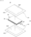
- Fig. 1 is an exploded perspective view showing a pouch type battery cell according to an embodiment of the present disclosure.
- Fig. 2 is a perspective view showing a state in which the pouch type battery cell of Fig. 1 is assembled.
- Fig. 3 is a cross-sectional view taken along the cutting line A-A' of Fig. 2 .
- Fig. 4 is an enlarged cross-sectional view of the region P of Fig. 3 .
- the pouch type battery cell 100 can be manufactured by housing an electrode assembly 200 inside a pouch case 300 and then sealing the case.
- the electrode assembly 200 may include a cathode, an anode, and a separator disposed between the cathode and the anode.
- the electrode assembly 200 may be a stack type electrode assembly, a jelly-roll type electrode assembly, or a stack/folding type electrode assembly.
- Each of the cathode and the anode includes an electrode tab 210t, and the electrode leads 210 and 220 each connected to the electrode tab 210t may be exposed to the outside of the pouch case 300.
- the electrode leads 210 and 220 can be located respectively in the sealing part 300S in a state of being covered with a lead film 600 so as to secure a sealing property and an insulation property.
- the pouch case 300 is composed of a laminate sheet, and may include a resin layer for heat fusion and a metal layer for preventing material penetration.
- the pouch case 300 may include an upper case 310 and a lower case 320.
- the upper case 310 may include an inside resin layer 310a for sealing, a metal layer 310b for preventing material penetration, and an outside resin layer 310c.
- the layer structure concerning the upper case 310 described above may be equally applied even to a lower case 320.
- the lower case 320 may include an inside resin layer, a metal layer and an outside resin layer along a direction away from the electrode assembly 200.
- the outside resin layer 310c and the packaging sheet layer can have excellent tensile strength and weather resistance compared to their thickness and have electrical insulation property in order to protect the pouch type secondary battery from the outside.
- the outside resin layer 310c may include a polyethylene terephthalate (PET) resin or a nylon resin.
- PET polyethylene terephthalate
- the metal layer 310b can prevent air, moisture and the like from flowing into the pouch type battery layer 100.
- the metal layer 310b may include aluminum (Al).
- the inside resin layer 310a can be heat-fused to each other by heat and pressure applied in a state where the electrode assembly 200 is built-in.
- the inside resin layer 310a may include casted polypropylene (CPP) or polypropylene (PP).
- a concave-shaped housing part 300ST on which the electrode assembly 200 can be seated may be formed in each of the upper case 310 and the lower case 320.
- Sealing parts 300S1 and 300S2 may be provided along the outer periphery of the housing part 300ST for each of the upper case 310 and the lower case 320.
- the sealing part 300S 1 of the upper case 310 and the sealing part 300S2 of the lower case 320 can be heat-fused to each other to form the sealing part 300S and seal the pouch case 300.
- one side of the upper case and one side of the lower case can be integrally connected to each other, and the remaining three sides can be heat-fused.
- each of the plurality of cathodes and the plurality of anodes included in the electrode assembly 200 may include a cathode tab and an anode tab, to which electrode leads 210 and 220 are connected.
- one of the electrode leads 210 and 220 may be a cathode lead, and the other may be an anode lead.
- one of the electrode leads 210 and 220 connected to the electrode assembly 200 can protrude from one end part of the pouch case 300 and be exposed to the outside of the pouch case 300, and the other of the electrode leads 210 and 220 can protrude from the other one end part of the cell case 300 and be exposed to the outside of the cell case 300.
- the structure of the bidirectional electrode leads 210 and 220 has been described, but the electrode leads 210 and 220 can also be protruded in one direction.
- Fig. 5 is a view showing a pouch type battery manufacturing apparatus according to an embodiment of the present disclosure.
- a pouch type battery manufacturing apparatus 1000 includes a sealing tool 500 formed by assembling a plurality of sealing parts.
- the sealing tool 500 may include an upper sealing tool and a lower sealing tool.
- the upper sealing tool will be mainly described.
- the lower sealing tool has the same configuration as the upper sealing tool, and in order to seal the pouch type battery case, the upper sealing tool and the lower sealing tool can be disposed so as to face the pouch-type battery, respectively.
- the plurality of sealing parts comprises a central sealing part 510, a first sealing part 520 located on the left and right sides of the central sealing part 510, and a second sealing part 530 disposed outside the first sealing part 520.
- the central sealing part 510, the first sealing part 520, and the second sealing part 530 can be assembled and coupled, or separated adjacent to each other.
- the pouch type battery manufacturing apparatus shown in Fig. 5 may form the sealing part 300S shown along the y-axis direction of Fig. 2 .
- the pouch type battery manufacturing apparatus of Fig. 5 is a view seen in the x direction of Fig. 3 .
- the central sealing part 510 corresponds to the electrode lead 210 covered by the lead film 600, and an upper surface and a lower surface of the central sealing part 510 are parallel to each other.
- the upper surface of the first sealing part 520 has a horizontal surface parallel to the upper surface of the central sealing part 510, and a lower surface of the first sealing part 520 may have two inclined surfaces 520s1 and 520s2 and a horizontal surface 520h for connecting the two inclined surfaces 520s1 and 520s2.
- the first inclined surface 520s1 of the first sealing part 520 may correspond to an inclined portion 600s of the lead film 600.
- the inclined portion 600s of the lead film 600 may correspond to an edge in the width direction of the electrode lead 210.
- the width direction of the electrode lead 210 may refer to a direction that is perpendicular to a direction in which the electrode lead 210 protrudes from the electrode assembly 200 and is parallel to a surface on which the sealing part 300S is formed.
- the edge in the width direction of the electrode lead 210 may have a tapered shape.
- the left and right edge parts of the electrode lead 210 can be designed so as to have a tapered shape, thereby improving the adhesiveness of the edge part of the electrode lead 210.
- the lead film 600 includes an upper lead film 600a and a lower lead film 600b, and the horizontal surface 520h of the first sealing part 520 may correspond to a portion in which the upper lead film 600a and the lower lead film 600b are sealed in a horizontal direction.
- the second sealing part 530 may be disposed on the outermost part and may be assembled and coupled to the first sealing part 520.
- Fig. 6 is a view showing a pouch type battery manufacturing apparatus according to a comparative example of the present disclosure.
- the pouch type battery manufacturing apparatus may have a sealing tool 10 having a first groove GV1 and a second groove GV2 through mold processing. That is, the sealing tool 10 according to the comparative example may be integrally formed by designing the width and depth of the groove according to the target sealing thickness and the dimensions of the electrode lead and the lead film. According to this, the thickness and width can be applied only to a single standard sealing which was originally designed, and if the design standard is changed, a new sealing tool must be manufactured to match it.
- the sealing tool according to the present embodiment is a sealing tool 500 formed by assembling a plurality of sealing parts
- each sealing part constituting the sealing tool can be manufactured to have various thicknesses, widths, angles and the like, and thus, the manufactured sealing parts can be assembled as desired to form a sealing tool.
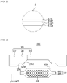
- Fig. 7 is a view showing a pouch type battery manufacturing apparatus according to another embodiment of the present disclosure.
- the first sealing part 520 of Fig. 5 includes a 1-1 sealing part 520a connected to the central sealing part 510, and a 1-2 sealing part 520b located outside the 1-1 sealing part 520a and assembled with the 1-1 sealing part 520a.
- the lower surface of the 1-1 sealing part 520a has one inclined surface 520s1
- the lower surface of the 1-2 sealing part 520b has a horizontal surface 520h connected to the inclined surface 520s1 of the 1-1 sealing part (520a), and an inclined surface 520s2 connected to the horizontal surface 520h of the 1-2 sealing part 520b.
- the horizontal surface 520h of the 1-2 sealing part 520b according to the present embodiment may correspond to a portion in which the upper lead film 600a and the lower lead film 600b are sealed in a horizontal direction.
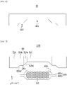
- Fig. 8 is a view showing a pouch type battery manufacturing apparatus according to another embodiment of the present disclosure.
- the 1-2 sealing part 520b of Fig. 7 may be a form in which two sealing parts 520b1 and 520b2 are assembled.
- the 1-2 sealing part 520b of Fig. 7 includes a 1-2-1 sealing part 520b1 connected to the 1-1 sealing part 520a, and a 1-2-2 sealing part 520b2 located outside the 1-2-1 sealing part 520b1 and assembled with the 1-2-1 sealing part 520b1.
- the lower surface of the 1-2-1 sealing part 520b1 has a horizontal surface 520h connected to the inclined surface 520s1 of the 1-1 sealing part 520a
- the lower surface of the 1-2-2 sealing part 520b2 may have an inclined surface 520s2 connected to the horizontal surface 520h of the 1-2-1 sealing part 520b1.
- the horizontal surface 520h of the 1-2-1 sealing part 520b1 according to the present embodiment may correspond to a portion in which the upper lead film 600a and the lower lead film 600b are sealed in a horizontal direction.
- Fig. 9 is a view showing a method of coupling a plurality of sealing parts constituting the pouch type battery manufacturing apparatus according to an embodiment of the present disclosure.
- a plurality of sealing parts 510, 520a, 520b1, 520b2 and 530 constituting the sealing tool 500 according to the present embodiment are disposed along the horizontal direction, and a hole part HP formed along a horizontal direction is formed in each of the plurality of sealing parts 510, 520a , 520b1, 520b2 and 530.
- the plurality of sealing parts 510, 520a, 520b1, 520b2 and 530 can be coupled to each other by a fixing member 700 passing through the hole parts HP.
- the fixing member 700 can be fixed on both sides of the sealing tool 500 by a bolt/nut method.
- Fig. 10 is a view showing a method of coupling a plurality of sealing parts constituting the pouch type battery manufacturing apparatus according to another embodiment of the present disclosure.
- a protrusion 500P and a groove 500D is formed in each of the plurality of sealing parts 510, 520a, 520b1, 520b2 and 530.
- the protrusion 500P1 of the central sealing part 510 may be inserted into and fixed to a recessed part 500D1 of the 1-1 sealing part 520a.
- the protrusion 500P2 of the 1-1 sealing part 520a can be inserted into and fixed to the recessed part 500D2 of the 1-2-1 sealing part 520b1.
- the protrusion of the sealing part can be coupled to the groove of the adjacent sealing part, so that the plurality of sealing parts 510, 520a, 520b1, 520b2 and 530 can be coupled to each other.
- the outermost shape of the protrusion 500P and the groove 500D may be variously applied so as to include a locally small radius of curvature and/or edge, such as a spherical shape, a prismatic shape, or a cylindrical shape.
- the direction in which the protrusion 500P and the groove 500D are formed may be the same as the direction in which the sealing parts 510, 520a, 520b1, 520b2 and 530 are assembled.
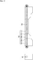
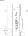
- Fig. 11 is a view showing a pouch type battery before sealing using the pouch type battery manufacturing apparatus according to an embodiment of the present disclosure.
- Fig. 12 is a view showing a pouch type battery after sealing using the pouch type battery manufacturing apparatus of Fig. 11 .
- an upper case 310 and a lower case 320 may be disposed on the upper and lower parts of the electrode lead 210 wrapped with the lead film 600, respectively. Then, the upper sealing tool 500a is disposed on the upper part of the upper case 310, the lower sealing tool 500b is disposed on the lower part of the lower case 320, and then the upper sealing tool 500a and the lower sealing tool 500b are pressed to seal the pouch case 300, the lead film 600, and the like as shown in Fig. 12 , thereby realizing the packaging of the pouch type secondary battery.
- the plurality of sealing parts are decreased in thickness toward the central part of the upper sealing tool 500a and the lower sealing tool 500b, and at least two of the plurality of sealing parts may be formed with a groove toward the center of the upper sealing tool 500a and the lower sealing tool 500b.
- the plurality of sealing parts may be formed in symmetrical shapes with respect to the center of the upper sealing tool 500a and the lower sealing tool 500b.
Landscapes
- Engineering & Computer Science (AREA)
- Mechanical Engineering (AREA)
- Chemical & Material Sciences (AREA)
- Chemical Kinetics & Catalysis (AREA)
- Electrochemistry (AREA)
- General Chemical & Material Sciences (AREA)
- Manufacturing & Machinery (AREA)
- Sealing Battery Cases Or Jackets (AREA)
- Connection Of Batteries Or Terminals (AREA)
Abstract
Description
- This application claims the benefit of
Korean Patent Application No. 10-2020-0141978 filed on October 29, 2020 - The present disclosure relates to a pouch type battery manufacturing apparatus, and more particularly, to a pouch type battery manufacturing apparatus having a modularized sealing tool.
- As the demands for portable electronic products such as notebooks, video cameras and cellular phones are rapidly increased in these days, and development of electric vehicles, energy storage batteries, robots, satellites, etc. is under active progress, numerous studies are being made on secondary batteries being used as the driving power source.
- The electrode assembly mounted in the battery case is a power generating element, having a cathode/separator/anode stack structure, which can be charged and discharged, and the electrode assembly is classified into a jelly-roll type, a stacked type and a stacked/folded type. The jelly-roll type electrode assembly is configured to have a structure in which a long sheet type cathode and a long sheet type anode, to which active materials are applied, are wound in a state where a separator is interposed between the cathode and the anode, the stacked type electrode assembly is configured to have a structure in which a large number of cathodes having a predetermined size and a large number of anodes having a predetermined size are sequentially stacked in a state in which separators are interposed between the cathodes and the anodes, and the stacked/folded type electrode assembly is a combination of the jelly-roll type electrode assembly and the stacked type electrode assembly. Among them, the jelly-roll type electrode assembly has advantages in that manufacturing is easy and an energy density per unit weight is high.
- Meanwhile, based on the shape of a battery case, a secondary battery is classified into a cylindrical battery where an electrode assembly is built into a cylindrical metal can, a prismatic battery where an electrode assembly is built into a prismatic metal can, and a pouch-type battery where an electrode assembly is built into a pouch type case formed of an aluminum laminate sheet.
- A pouch type secondary battery includes an electrode assembly in which an electrode and a separator are alternately laminated, and a pouch case for housing the electrode assembly. The method for manufacturing the secondary battery includes an electrode production step of producing an electrode, an electrode assembly production step of alternately laminating electrodes and a separator to produce an electrode assembly, an electrode lead coupling step of coupling electrode lead to the electrode assembly, and a pouch sealing step of housing the electrode assembly in a pouch case in a state where the tip of the electrode lead is drawn out to the outside, and sealing the edge surface of the pouch case.
- Here, the pouch sealing step can be performed by sealing the edge surface of the pouch case using a sealing device including an upper tool and a lower tool.
- However, the sealing device can stably seal the edge surface of the pouch case without an electrode lead, but the edge surface of the pouch case having the electrode lead has a problem that a sealing defect occurs due to the drawing of the electrode lead.
- In particular, the width, thickness, and position of the electrode lead may differ depending on the capacity of the secondary battery, the design of the secondary battery, the material of the electrode lead, and the sales company, and therefore, there is a problem that a new sealing device needs to be manufactured every time when the width, thickness, and position of the electrode lead are changed.
- It is an object of the present disclosure to provide a pouch type battery manufacturing apparatus having a modularized sealing tool.
- However, the problem to be solved by embodiments of the present disclosure is not limited to the above-described problems, and can be variously expanded within the scope of the technical idea included in the present disclosure.
- According to an embodiment of the present disclosure, there is provided A pouch type battery manufacturing apparatus, which is a secondary battery manufacturing apparatus for sealing a pouch type battery case, the apparatus comprising: an upper sealing tool and a lower sealing tool, wherein each of the upper sealing tool and the lower sealing tool is formed by assembling a plurality of sealing parts, wherein the plurality of sealing parts comprises a central sealing part, a first sealing part located on the left and right sides of the central sealing part, and a second sealing part disposed outside the first sealing part, and wherein the central sealing part corresponds to an electrode lead covered by a lead film, and an upper surface and a lower surface of the central sealing part are parallel to each other.
- One of the upper surface and the lower surface of the first sealing part may have two inclined surfaces and a horizontal surface connecting the two inclined surfaces.
- The first sealing part comprises a 1-1 sealing part connected to the central sealing part, and a 1-2 sealing part located outside the 1-1 sealing part and assembled with the 1-1 sealing part, and one of the upper surface and the lower surface of the 1-1 sealing part has one inclined surface, and one of the upper surface and the lower surface of the 1-2 sealing part may have a horizontal surface connected to the inclined surface of the 1-1 sealing part, and an inclined surface connected to the horizontal surface of the 1-2 sealing part.
- The 1-2 sealing part may be a form in which two sealing parts are assembled.
- The inclined surface of the 1-1 sealing part may correspond to an inclined portion of the lead film.
- The inclined portion of the lead film corresponds to an edge in the width direction of the electrode lead, and the edge in the width direction of the electrode lead may have a tapered shape.
- The lead film comprises an upper lead film and a lower lead film, and the 1-2 sealing part may correspond to a portion in which the upper lead film and the lower lead film are sealed in a horizontal direction.
- The pouch type battery manufacturing apparatus comprises an upper case and a lower case of the pouch type battery case, wherein the second sealing part may correspond to a portion in which the upper case and the lower case are sealed in a horizontal direction.
- The plurality of sealing parts are disposed along a horizontal direction, a hole part formed along a horizontal direction is formed in each of the plurality of sealing parts, and the plurality of sealing parts may be coupled by a fixing member passing through the hole parts.
- At least one of a protrusion and a groove is formed in each of the plurality of sealing parts, and the protrusion of the sealing part is coupled to the groove of the adjacent sealing part and thus, the sealing parts are coupled to each other.
- A direction in which the protrusion and the groove may be formed is the same as the direction in which the sealing parts are assembled.
- The plurality of sealing parts is decreased in thickness toward the central part of the upper sealing tool and the lower sealing tool, and at least two of the plurality of sealing parts may be formed with a groove toward the central part of the upper sealing tool and the lower sealing tool.
- The plurality of sealing parts may be formed in symmetrical shapes with respect to the center of the upper sealing tool and the lower sealing tool.
- According to embodiments of the present disclosure, the respective modules constituting the sealing tool can be manufactured to have various thicknesses, widths, angles and the like, and thus, the manufactured modules can be assembled as desired to form a sealing tool. By implementing a module-type sealing tool divided into a plurality of sections in this way, it is possible to prevent unnecessary mold production and quickly cope with diversification of design.
- The effects of the present disclosure are not limited to the effects mentioned above and additional other effects not described above will be clearly understood from the description of the appended claims by those skilled in the art.
-
-
Fig. 1 is an exploded perspective view showing a pouch type battery cell according to an embodiment of the present disclosure; -
Fig. 2 is a perspective view showing a state in which the pouch type battery cell ofFig. 1 is assembled; -
Fig. 3 is a cross-sectional view taken along the cutting line A-A' ofFig. 2 ; -
Fig. 4 is an enlarged cross-sectional view of the region P ofFig. 3 ; -
Fig. 5 is a view showing a pouch type battery manufacturing apparatus according to an embodiment of the present disclosure; -
Fig. 6 is a view showing a pouch type battery manufacturing apparatus according to a comparative example of the present disclosure; -
Fig. 7 is a view showing a pouch type battery manufacturing apparatus according to another embodiment of the present disclosure; -
Fig. 8 is a view showing a pouch type battery manufacturing apparatus according to another embodiment of the present disclosure; -
Fig. 9 is a view showing a method of coupling a plurality of sealing parts constituting The pouch type battery manufacturing apparatus according to an embodiment of the present disclosure; -
Fig. 10 is a view showing a method of coupling a plurality of sealing parts constituting the pouch type battery manufacturing apparatus according to another embodiment of the present disclosure; -
Fig. 11 is a view showing a pouch type battery before sealing using the pouch type battery manufacturing apparatus according to an embodiment of the present disclosure; and -
Fig. 12 is a view showing a pouch type battery after sealing using the pouch type battery manufacturing apparatus ofFig. 11 . - Hereinafter, various embodiments of the present disclosure will be described in detail with reference to the accompanying drawings so that those skilled in the art can easily carry out them. The present disclosure may be modified in various different ways, and is not limited to the embodiments set forth herein.
- A description of parts not related to the description will be omitted herein for clarity, and like reference numerals designate like elements throughout the description.
- Further, in the drawings, the size and thickness of each element are arbitrarily illustrated for convenience of description, and the present disclosure is not necessarily limited to those illustrated in the drawings. In the drawings, the thickness of layers, regions, etc. are exaggerated for clarity. In the drawings, for convenience of description, the thicknesses of some layers and regions are exaggerated.
- In addition, it will be understood that when an element such as a layer, film, region, or plate is referred to as being "on" or "above" another element, it can be directly on the other element or intervening elements may also be present. In contrast, when an element is referred to as being "directly on" another element, it means that other intervening elements are not present. Further, the word "on" or "above" means disposed on or below a reference portion, and does not necessarily mean being disposed on the upper end of the reference portion toward the opposite direction of gravity.
- Further, throughout the description, when a portion is referred to as "including" a certain component, it means that the portion can further include other components, without excluding the other components, unless otherwise stated.
- Further, throughout the description, when referred to as "planar", it means when a target portion is viewed from the upper side, and when referred to as "cross-sectional", it means when a target portion is viewed from the side of a cross section cut vertically.
-
Fig. 1 is an exploded perspective view showing a pouch type battery cell according to an embodiment of the present disclosure.Fig. 2 is a perspective view showing a state in which the pouch type battery cell ofFig. 1 is assembled.Fig. 3 is a cross-sectional view taken along the cutting line A-A' ofFig. 2 .Fig. 4 is an enlarged cross-sectional view of the region P ofFig. 3 . - Referring to
Figs. 1 to 3 , the pouchtype battery cell 100 according to the present embodiment can be manufactured by housing anelectrode assembly 200 inside apouch case 300 and then sealing the case. Theelectrode assembly 200 may include a cathode, an anode, and a separator disposed between the cathode and the anode. Theelectrode assembly 200 may be a stack type electrode assembly, a jelly-roll type electrode assembly, or a stack/folding type electrode assembly. - Each of the cathode and the anode includes an
electrode tab 210t, and the electrode leads 210 and 220 each connected to theelectrode tab 210t may be exposed to the outside of thepouch case 300. In addition, the electrode leads 210 and 220 can be located respectively in the sealingpart 300S in a state of being covered with alead film 600 so as to secure a sealing property and an insulation property. - The
pouch case 300 is composed of a laminate sheet, and may include a resin layer for heat fusion and a metal layer for preventing material penetration. Thepouch case 300 may include anupper case 310 and alower case 320. - Specifically, referring to
Fig. 4 , theupper case 310 may include an inside resin layer 310a for sealing, a metal layer 310b for preventing material penetration, and anoutside resin layer 310c. - The layer structure concerning the
upper case 310 described above may be equally applied even to alower case 320. In other words, thelower case 320 may include an inside resin layer, a metal layer and an outside resin layer along a direction away from theelectrode assembly 200. - The
outside resin layer 310c and the packaging sheet layer can have excellent tensile strength and weather resistance compared to their thickness and have electrical insulation property in order to protect the pouch type secondary battery from the outside. Theoutside resin layer 310c may include a polyethylene terephthalate (PET) resin or a nylon resin. The metal layer 310b can prevent air, moisture and the like from flowing into the pouchtype battery layer 100. The metal layer 310b may include aluminum (Al). The inside resin layer 310a can be heat-fused to each other by heat and pressure applied in a state where theelectrode assembly 200 is built-in. The inside resin layer 310a may include casted polypropylene (CPP) or polypropylene (PP). - Referring back to
Figs. 1 to 3 , a concave-shaped housing part 300ST on which theelectrode assembly 200 can be seated may be formed in each of theupper case 310 and thelower case 320. Sealing parts 300S1 and 300S2 may be provided along the outer periphery of the housing part 300ST for each of theupper case 310 and thelower case 320. The sealingpart 300S 1 of theupper case 310 and the sealing part 300S2 of thelower case 320 can be heat-fused to each other to form the sealingpart 300S and seal thepouch case 300. - In another embodiment of the present disclosure, one side of the upper case and one side of the lower case can be integrally connected to each other, and the remaining three sides can be heat-fused.
- On the other hand, each of the plurality of cathodes and the plurality of anodes included in the
electrode assembly 200 may include a cathode tab and an anode tab, to which electrode leads 210 and 220 are connected. Specifically, one of the electrode leads 210 and 220 may be a cathode lead, and the other may be an anode lead. As described above, one of the electrode leads 210 and 220 connected to theelectrode assembly 200 can protrude from one end part of thepouch case 300 and be exposed to the outside of thepouch case 300, and the other of the electrode leads 210 and 220 can protrude from the other one end part of thecell case 300 and be exposed to the outside of thecell case 300. In the present embodiment, the structure of the bidirectional electrode leads 210 and 220 has been described, but the electrode leads 210 and 220 can also be protruded in one direction. -
Fig. 5 is a view showing a pouch type battery manufacturing apparatus according to an embodiment of the present disclosure. - Referring to
Fig. 5 , a pouch typebattery manufacturing apparatus 1000 according to the present embodiment includes asealing tool 500 formed by assembling a plurality of sealing parts. Thesealing tool 500 may include an upper sealing tool and a lower sealing tool. Here, the upper sealing tool will be mainly described. The lower sealing tool has the same configuration as the upper sealing tool, and in order to seal the pouch type battery case, the upper sealing tool and the lower sealing tool can be disposed so as to face the pouch-type battery, respectively. - The plurality of sealing parts according to the present embodiment comprises a
central sealing part 510, afirst sealing part 520 located on the left and right sides of thecentral sealing part 510, and asecond sealing part 530 disposed outside thefirst sealing part 520. Thecentral sealing part 510, thefirst sealing part 520, and thesecond sealing part 530 can be assembled and coupled, or separated adjacent to each other. - The pouch type battery manufacturing apparatus shown in
Fig. 5 may form the sealingpart 300S shown along the y-axis direction ofFig. 2 . In other words, the pouch type battery manufacturing apparatus ofFig. 5 is a view seen in the x direction ofFig. 3 . Thecentral sealing part 510 corresponds to theelectrode lead 210 covered by thelead film 600, and an upper surface and a lower surface of thecentral sealing part 510 are parallel to each other. The upper surface of thefirst sealing part 520 has a horizontal surface parallel to the upper surface of thecentral sealing part 510, and a lower surface of thefirst sealing part 520 may have two inclined surfaces 520s1 and 520s2 and ahorizontal surface 520h for connecting the two inclined surfaces 520s1 and 520s2. - Referring to
Figs. 3 and5 , the first inclined surface 520s1 of thefirst sealing part 520 may correspond to aninclined portion 600s of thelead film 600. Theinclined portion 600s of thelead film 600 may correspond to an edge in the width direction of theelectrode lead 210. Here, the width direction of theelectrode lead 210 may refer to a direction that is perpendicular to a direction in which theelectrode lead 210 protrudes from theelectrode assembly 200 and is parallel to a surface on which thesealing part 300S is formed. The edge in the width direction of theelectrode lead 210 may have a tapered shape. The left and right edge parts of theelectrode lead 210 can be designed so as to have a tapered shape, thereby improving the adhesiveness of the edge part of theelectrode lead 210. - The
lead film 600 according to the present embodiment includes anupper lead film 600a and alower lead film 600b, and thehorizontal surface 520h of thefirst sealing part 520 may correspond to a portion in which theupper lead film 600a and thelower lead film 600b are sealed in a horizontal direction. - The
second sealing part 530 according to the present embodiment may be disposed on the outermost part and may be assembled and coupled to thefirst sealing part 520. -
Fig. 6 is a view showing a pouch type battery manufacturing apparatus according to a comparative example of the present disclosure. - Referring to
Fig. 6 , The pouch type battery manufacturing apparatus according to the comparative example may have asealing tool 10 having a first groove GV1 and a second groove GV2 through mold processing. That is, the sealingtool 10 according to the comparative example may be integrally formed by designing the width and depth of the groove according to the target sealing thickness and the dimensions of the electrode lead and the lead film. According to this, the thickness and width can be applied only to a single standard sealing which was originally designed, and if the design standard is changed, a new sealing tool must be manufactured to match it. On the other hand, since the sealing tool according to the present embodiment is asealing tool 500 formed by assembling a plurality of sealing parts, each sealing part constituting the sealing tool can be manufactured to have various thicknesses, widths, angles and the like, and thus, the manufactured sealing parts can be assembled as desired to form a sealing tool. -
Fig. 7 is a view showing a pouch type battery manufacturing apparatus according to another embodiment of the present disclosure. - Referring to
Fig. 7 , in the pouch typebattery manufacturing apparatus 1100 according to the present embodiment, thefirst sealing part 520 ofFig. 5 includes a 1-1sealing part 520a connected to thecentral sealing part 510, and a 1-2sealing part 520b located outside the 1-1sealing part 520a and assembled with the 1-1sealing part 520a. At this time, the lower surface of the 1-1sealing part 520a has one inclined surface 520s1, and the lower surface of the 1-2sealing part 520b has ahorizontal surface 520h connected to the inclined surface 520s1 of the 1-1 sealing part (520a), and an inclined surface 520s2 connected to thehorizontal surface 520h of the 1-2sealing part 520b. Thehorizontal surface 520h of the 1-2sealing part 520b according to the present embodiment may correspond to a portion in which theupper lead film 600a and thelower lead film 600b are sealed in a horizontal direction. - In addition to the differences described above, all the contents described in the embodiment of
Fig. 5 can be applied to the present embodiment. -
Fig. 8 is a view showing a pouch type battery manufacturing apparatus according to another embodiment of the present disclosure. - Referring to
Fig. 8 , in the pouch typebattery manufacturing apparatus 1200 according to the present embodiment, the 1-2sealing part 520b ofFig. 7 may be a form in which two sealing parts 520b1 and 520b2 are assembled. Specifically, the 1-2sealing part 520b ofFig. 7 includes a 1-2-1 sealing part 520b1 connected to the 1-1sealing part 520a, and a 1-2-2 sealing part 520b2 located outside the 1-2-1 sealing part 520b1 and assembled with the 1-2-1 sealing part 520b1. At this time, the lower surface of the 1-2-1 sealing part 520b1 has ahorizontal surface 520h connected to the inclined surface 520s1 of the 1-1sealing part 520a, and the lower surface of the 1-2-2 sealing part 520b2 may have an inclined surface 520s2 connected to thehorizontal surface 520h of the 1-2-1 sealing part 520b1. Thehorizontal surface 520h of the 1-2-1 sealing part 520b1 according to the present embodiment may correspond to a portion in which theupper lead film 600a and thelower lead film 600b are sealed in a horizontal direction. - In addition to the differences described above, all the contents described in the embodiment of
Fig. 7 can be applied to the present embodiment. -
Fig. 9 is a view showing a method of coupling a plurality of sealing parts constituting the pouch type battery manufacturing apparatus according to an embodiment of the present disclosure. - Referring to
Fig. 9 , a plurality of sealingparts sealing tool 500 according to the present embodiment are disposed along the horizontal direction, and a hole part HP formed along a horizontal direction is formed in each of the plurality of sealingparts parts member 700 passing through the hole parts HP. The fixingmember 700 can be fixed on both sides of thesealing tool 500 by a bolt/nut method. -
Fig. 10 is a view showing a method of coupling a plurality of sealing parts constituting the pouch type battery manufacturing apparatus according to another embodiment of the present disclosure. - Referring to
Fig. 10 , at least one of aprotrusion 500P and agroove 500D is formed in each of the plurality of sealingparts Fig. 10 , the protrusion 500P1 of thecentral sealing part 510 may be inserted into and fixed to a recessed part 500D1 of the 1-1sealing part 520a. Similarly, the protrusion 500P2 of the 1-1sealing part 520a can be inserted into and fixed to the recessed part 500D2 of the 1-2-1 sealing part 520b1. In this manner, the protrusion of the sealing part can be coupled to the groove of the adjacent sealing part, so that the plurality of sealingparts protrusion 500P and thegroove 500D may be variously applied so as to include a locally small radius of curvature and/or edge, such as a spherical shape, a prismatic shape, or a cylindrical shape. - According to the present embodiment, the direction in which the
protrusion 500P and thegroove 500D are formed may be the same as the direction in which the sealingparts -
Fig. 11 is a view showing a pouch type battery before sealing using the pouch type battery manufacturing apparatus according to an embodiment of the present disclosure.Fig. 12 is a view showing a pouch type battery after sealing using the pouch type battery manufacturing apparatus ofFig. 11 . - Referring to
Fig. 11 , anupper case 310 and alower case 320 may be disposed on the upper and lower parts of theelectrode lead 210 wrapped with thelead film 600, respectively. Then, theupper sealing tool 500a is disposed on the upper part of theupper case 310, thelower sealing tool 500b is disposed on the lower part of thelower case 320, and then theupper sealing tool 500a and thelower sealing tool 500b are pressed to seal thepouch case 300, thelead film 600, and the like as shown inFig. 12 , thereby realizing the packaging of the pouch type secondary battery. In the present embodiment, the plurality of sealing parts are decreased in thickness toward the central part of theupper sealing tool 500a and thelower sealing tool 500b, and at least two of the plurality of sealing parts may be formed with a groove toward the center of theupper sealing tool 500a and thelower sealing tool 500b. In addition, the plurality of sealing parts may be formed in symmetrical shapes with respect to the center of theupper sealing tool 500a and thelower sealing tool 500b. - Although preferred embodiments of the present disclosure have been described above, the scope of the present disclosure is not limited thereto, and numerous other variations and modifications can be made by those skilled in the art using the principles of the invention defined in the appended claims, which also fall within the spirit and scope of the present disclosure.
-
- 500: sealing tool
- 500P: protrusion
- 500D: recessed part
- 510: central sealing part
- 520: first sealing part
- 530: second sealing part
- 600: lead film
- 700: fixing member
Claims (13)
- A pouch type battery manufacturing apparatus, which is a secondary battery manufacturing apparatus for sealing a pouch type battery case, the apparatus comprising:an upper sealing tool and a lower sealing tool,wherein each of the upper sealing tool and the lower sealing tool is formed by assembling a plurality of sealing parts,wherein the plurality of sealing parts comprises a central sealing part, a first sealing part located on the left and right sides of the central sealing part, and a second sealing part disposed outside the first sealing part, andwherein the central sealing part corresponds to an electrode lead covered by a lead film, and an upper surface and a lower surface of the central sealing part are parallel to each other.
- The pouch type battery manufacturing apparatus according to claim 1, wherein:
one of the upper surface and the lower surface of the first sealing part has two inclined surfaces and a horizontal surface connecting the two inclined surfaces. - The pouch type battery manufacturing apparatus according to claim 2, wherein:the first sealing part comprises a 1-1 sealing part connected to the central sealing part, and a 1-2 sealing part located outside the 1-1 sealing part and assembled with the 1-1 sealing part, andone of the upper surface and the lower surface of the 1-1 sealing part has one inclined surface, and one of the upper surface and the lower surface of the 1-2 sealing part has a horizontal surface connected to the inclined surface of the 1-1 sealing part, and an inclined surface connected to the horizontal surface of the 1-2 sealing part.
- The pouch type battery manufacturing apparatus according to claim 3, wherein:
the 1-2 sealing part is a form in which two sealing parts are assembled. - The pouch type battery manufacturing apparatus according to claim 3, wherein:
the inclined surface of the 1-1 sealing part corresponds to an inclined portion of the lead film. - The pouch type battery manufacturing apparatus according to claim 5, wherein:
the inclined portion of the lead film corresponds to an edge in the width direction of the electrode lead, and the edge in the width direction of the electrode lead has a tapered shape. - The pouch type battery manufacturing apparatus according to claim 3, wherein:
the lead film comprises an upper lead film and a lower lead film, and the 1-2 sealing part corresponds to a portion in which the upper lead film and the lower lead film are sealed in a horizontal direction. - The pouch type battery manufacturing apparatus according to claim 3,which comprises an upper case and a lower case of the pouch type battery case,wherein the second sealing part corresponds to a portion in which the upper case and the lower case are sealed in a horizontal direction.
- The pouch type battery manufacturing apparatus according to claim 1, wherein:the plurality of sealing parts are disposed along a horizontal direction,a hole part formed along a horizontal direction is formed in each of the plurality of sealing parts, andthe plurality of sealing parts are coupled by a fixing member passing through the hole parts.
- The pouch type battery manufacturing apparatus according to claim 1, wherein:at least one of a protrusion and a groove is formed in each of the plurality of sealing parts, andthe protrusion of the sealing part is coupled to the groove of the adjacent sealing part and thus, the sealing parts are coupled to each other.
- The pouch type battery manufacturing apparatus according to claim 10, wherein:
a direction in which the protrusion and the groove are formed is the same as the direction in which the sealing parts are assembled. - The pouch type battery manufacturing apparatus according to claim 1, wherein:the plurality of sealing parts is decreased in thickness toward the central part of the upper sealing tool and the lower sealing tool, andat least two of the plurality of sealing parts are formed with a groove toward the central part of the upper sealing tool and the lower sealing tool.
- The pouch type battery manufacturing apparatus according to claim 1, wherein:
the plurality of sealing parts are formed in symmetrical shapes with respect to the center of the upper sealing tool and the lower sealing tool.
Applications Claiming Priority (2)
| Application Number | Priority Date | Filing Date | Title |
|---|---|---|---|
| KR1020200141978A KR20220057098A (en) | 2020-10-29 | 2020-10-29 | Apparatus of manufacturing pouch type battery |
| PCT/KR2021/011912 WO2022092541A1 (en) | 2020-10-29 | 2021-09-03 | Apparatus of manufacturing pouch type battery |
Publications (2)
| Publication Number | Publication Date |
|---|---|
| EP4056352A1 true EP4056352A1 (en) | 2022-09-14 |
| EP4056352A4 EP4056352A4 (en) | 2023-06-21 |
Family
ID=81382862
Family Applications (1)
| Application Number | Title | Priority Date | Filing Date |
|---|---|---|---|
| EP21886538.4A Pending EP4056352A4 (en) | 2020-10-29 | 2021-09-03 | APPARATUS FOR MANUFACTURING A POCKET TYPE BATTERY |
Country Status (6)
| Country | Link |
|---|---|
| US (1) | US12176475B2 (en) |
| EP (1) | EP4056352A4 (en) |
| JP (1) | JP7517649B2 (en) |
| KR (1) | KR20220057098A (en) |
| CN (1) | CN114761208B (en) |
| WO (1) | WO2022092541A1 (en) |
Cited By (1)
| Publication number | Priority date | Publication date | Assignee | Title |
|---|---|---|---|---|
| EP4564542A1 (en) | 2023-11-29 | 2025-06-04 | LG Energy Solution, Ltd. | Sealing block, sealing apparatus and secondary battery |
Families Citing this family (2)
| Publication number | Priority date | Publication date | Assignee | Title |
|---|---|---|---|---|
| JP2025536085A (en) * | 2023-09-01 | 2025-10-30 | エルジー エナジー ソリューション リミテッド | Sealing tool for pouch-type secondary battery and sealing method for pouch-type secondary battery |
| KR102886047B1 (en) * | 2023-11-29 | 2025-11-14 | 주식회사 엘지에너지솔루션 | Sealing apparatus and secondary battery manufactured by the same |
Family Cites Families (22)
| Publication number | Priority date | Publication date | Assignee | Title |
|---|---|---|---|---|
| JPH0739604Y2 (en) * | 1989-07-25 | 1995-09-13 | 川崎炉材株式会社 | Molding equipment for refractory brick molding |
| CN1280155C (en) | 2000-01-26 | 2006-10-18 | 大日本印刷株式会社 | heat sealing method |
| JP3696028B2 (en) | 2000-02-14 | 2005-09-14 | トヨタ自動車株式会社 | Battery having film sealing structure and manufacturing method thereof |
| JP2001297738A (en) | 2000-04-17 | 2001-10-26 | Yuasa Corp | Sealed battery and method of manufacturing sealed battery |
| JP4363017B2 (en) | 2002-09-20 | 2009-11-11 | 日本電気株式会社 | Battery and battery manufacturing method |
| JP2005353503A (en) | 2004-06-14 | 2005-12-22 | Sii Micro Parts Ltd | Thin electrochemical cell |
| JP5082263B2 (en) | 2006-03-10 | 2012-11-28 | 日本電気株式会社 | Method for manufacturing film-covered electrical device |
| KR101166171B1 (en) | 2009-12-28 | 2012-07-18 | 부산대학교 산학협력단 | Apparatus and method for forming plate |
| CN103999253A (en) * | 2011-11-03 | 2014-08-20 | 约翰逊控制技术有限责任公司 | Prismatic lithium-ion battery cells with positively polarized rigid containers |
| WO2014188774A1 (en) | 2013-05-23 | 2014-11-27 | 日産自動車株式会社 | Laminated-type secondary battery manufacturing method and manufacturing device |
| KR20160096417A (en) * | 2015-02-05 | 2016-08-16 | 주식회사 엘지화학 | Apparatus and method for sealing pouch of secondary battery |
| KR101852250B1 (en) | 2015-04-02 | 2018-04-26 | 주식회사 엘지화학 | Sealing tool for a pouch type secondary battery |
| US10741822B2 (en) | 2015-05-07 | 2020-08-11 | Lg Chem, Ltd. | Pouch-type secondary battery including electrode lead having electrical current limiting function |
| KR102407509B1 (en) * | 2015-05-11 | 2022-06-13 | 에스케이온 주식회사 | Pouch sealing apparatus and method of manufacturing secondary battery |
| US10686207B2 (en) * | 2015-07-03 | 2020-06-16 | Semiconductor Energy Laboratory Co., Ltd. | Lithium-ion storage battery and electronic device |
| KR101672402B1 (en) | 2015-07-21 | 2016-11-03 | (주)휴민텍 | Acute angle bending apparatus for side sealing portion of pouch type secondary battery cell and acute angle bending method using the same |
| KR101670507B1 (en) | 2015-09-22 | 2016-10-31 | 주식회사 엠에스엘테크놀로지 | Light buoy |
| KR101947149B1 (en) | 2015-12-16 | 2019-02-13 | 주식회사 엘지화학 | Sealing Apparatus for Battery Case with Improved Application Area of Pressurization and Heat |
| CN106229540A (en) * | 2016-05-26 | 2016-12-14 | 江苏深苏电子科技有限公司 | A kind of flexible lithium ion battery and manufacture method thereof |
| DE102017219324A1 (en) * | 2017-10-27 | 2019-05-02 | Gs Yuasa International Ltd. | Battery cell and method for producing such |
| KR102081143B1 (en) | 2018-05-03 | 2020-02-25 | 박석남 | Modular Block Mold |
| KR102549539B1 (en) * | 2019-03-28 | 2023-06-29 | 주식회사 엘지에너지솔루션 | Sealing apparatus and method for secondary battery |
-
2020
- 2020-10-29 KR KR1020200141978A patent/KR20220057098A/en active Pending
-
2021
- 2021-09-03 JP JP2022531081A patent/JP7517649B2/en active Active
- 2021-09-03 US US17/788,951 patent/US12176475B2/en active Active
- 2021-09-03 EP EP21886538.4A patent/EP4056352A4/en active Pending
- 2021-09-03 WO PCT/KR2021/011912 patent/WO2022092541A1/en not_active Ceased
- 2021-09-03 CN CN202180006778.1A patent/CN114761208B/en active Active
Cited By (1)
| Publication number | Priority date | Publication date | Assignee | Title |
|---|---|---|---|---|
| EP4564542A1 (en) | 2023-11-29 | 2025-06-04 | LG Energy Solution, Ltd. | Sealing block, sealing apparatus and secondary battery |
Also Published As
| Publication number | Publication date |
|---|---|
| WO2022092541A1 (en) | 2022-05-05 |
| EP4056352A4 (en) | 2023-06-21 |
| CN114761208A (en) | 2022-07-15 |
| US12176475B2 (en) | 2024-12-24 |
| JP2023504410A (en) | 2023-02-03 |
| CN114761208B (en) | 2023-12-12 |
| JP7517649B2 (en) | 2024-07-17 |
| US20230343983A1 (en) | 2023-10-26 |
| KR20220057098A (en) | 2022-05-09 |
Similar Documents
| Publication | Publication Date | Title |
|---|---|---|
| JP6734482B2 (en) | Pouch exterior material for secondary battery, pouch type secondary battery using the same, and manufacturing method thereof | |
| US10892448B2 (en) | Pouch exterior for secondary battery, pouch-type secondary battery using the pouch exterior, and method of manufacturing the pouch-type secondary battery | |
| US12199246B2 (en) | Stacked prismatic architecture for electrochemical cell | |
| EP4056352A1 (en) | Apparatus of manufacturing pouch type battery | |
| KR102689862B1 (en) | Secondary battery | |
| EP3136466B1 (en) | Manufacture method of electrode assembly | |
| KR20170124298A (en) | Electrode assembly | |
| KR20200053463A (en) | Stacked prismatic architecture for electrochemical cells | |
| EP3211688B1 (en) | Rechargeable battery | |
| EP4191761A1 (en) | Battery cell and battery cell manufacturing apparatus | |
| EP4224621B1 (en) | Secondary battery and device including same | |
| US12614778B2 (en) | Pouch cell cutting apparatus and pouch cell manufacturing method | |
| US12519162B2 (en) | Battery cell and method of manufacturing the same | |
| EP4040582B1 (en) | Battery module and battery pack including the same | |
| EP4611163A1 (en) | Battery pack and method for manufacturing same | |
| KR20220094758A (en) | Battery module | |
| CN115428236B (en) | Battery cell manufacturing method and bag forming apparatus | |
| KR102274052B1 (en) | Method of manufacturing pocketed electrode plate | |
| CN116133820B (en) | Bag forming equipment | |
| EP4611127A1 (en) | Battery pack and method for manufacturing same | |
| KR102894079B1 (en) | Pouch type secondary battery and manufacturing method of the same | |
| EP4611126A1 (en) | Battery pack and manufacturing method therefor |
Legal Events
| Date | Code | Title | Description |
|---|---|---|---|
| STAA | Information on the status of an ep patent application or granted ep patent |
Free format text: STATUS: THE INTERNATIONAL PUBLICATION HAS BEEN MADE |
|
| PUAI | Public reference made under article 153(3) epc to a published international application that has entered the european phase |
Free format text: ORIGINAL CODE: 0009012 |
|
| STAA | Information on the status of an ep patent application or granted ep patent |
Free format text: STATUS: REQUEST FOR EXAMINATION WAS MADE |
|
| 17P | Request for examination filed |
Effective date: 20220609 |
|
| AK | Designated contracting states |
Kind code of ref document: A1 Designated state(s): AL AT BE BG CH CY CZ DE DK EE ES FI FR GB GR HR HU IE IS IT LI LT LU LV MC MK MT NL NO PL PT RO RS SE SI SK SM TR |
|
| REG | Reference to a national code |
Ref country code: DE Ref legal event code: R079 Free format text: PREVIOUS MAIN CLASS: B29C0065000000 Ipc: B29C0065020000 |
|
| A4 | Supplementary search report drawn up and despatched |
Effective date: 20230519 |
|
| RIC1 | Information provided on ipc code assigned before grant |
Ipc: B29L 31/34 20060101ALN20230512BHEP Ipc: B29L 9/00 20060101ALN20230512BHEP Ipc: B29K 705/02 20060101ALN20230512BHEP Ipc: B29K 77/00 20060101ALN20230512BHEP Ipc: B29K 67/00 20060101ALN20230512BHEP Ipc: B29K 23/00 20060101ALN20230512BHEP Ipc: H01M 50/105 20210101ALI20230512BHEP Ipc: H01M 10/04 20060101ALI20230512BHEP Ipc: B29C 65/02 20060101AFI20230512BHEP |
|
| DAV | Request for validation of the european patent (deleted) | ||
| DAX | Request for extension of the european patent (deleted) | ||
| GRAP | Despatch of communication of intention to grant a patent |
Free format text: ORIGINAL CODE: EPIDOSNIGR1 |
|
| STAA | Information on the status of an ep patent application or granted ep patent |
Free format text: STATUS: GRANT OF PATENT IS INTENDED |
|
| RIC1 | Information provided on ipc code assigned before grant |
Ipc: B29C 65/02 20060101AFI20260116BHEP Ipc: H01M 10/04 20060101ALI20260116BHEP Ipc: H01M 50/105 20210101ALI20260116BHEP Ipc: B29K 23/00 20060101ALN20260116BHEP Ipc: B29K 67/00 20060101ALN20260116BHEP Ipc: B29K 77/00 20060101ALN20260116BHEP Ipc: B29K 705/02 20060101ALN20260116BHEP Ipc: B29L 9/00 20060101ALN20260116BHEP Ipc: B29L 31/34 20060101ALN20260116BHEP |
|
| INTG | Intention to grant announced |
Effective date: 20260211 |
|
| P01 | Opt-out of the competence of the unified patent court (upc) registered |
Free format text: CASE NUMBER: UPC_APP_0009369_4056352/2026 Effective date: 20260311 |