EP4056328A1 - Method for recording a manoeuvre of an operable arm of a heavy vehicle - Google Patents
Method for recording a manoeuvre of an operable arm of a heavy vehicle Download PDFInfo
- Publication number
- EP4056328A1 EP4056328A1 EP22161475.3A EP22161475A EP4056328A1 EP 4056328 A1 EP4056328 A1 EP 4056328A1 EP 22161475 A EP22161475 A EP 22161475A EP 4056328 A1 EP4056328 A1 EP 4056328A1
- Authority
- EP
- European Patent Office
- Prior art keywords
- speed
- joint
- interest points
- control unit
- position signal
- Prior art date
- Legal status (The legal status is an assumption and is not a legal conclusion. Google has not performed a legal analysis and makes no representation as to the accuracy of the status listed.)
- Granted
Links
Images


Classifications
-
- G—PHYSICS
- G05—CONTROLLING; REGULATING
- G05B—CONTROL OR REGULATING SYSTEMS IN GENERAL; FUNCTIONAL ELEMENTS OF SUCH SYSTEMS; MONITORING OR TESTING ARRANGEMENTS FOR SUCH SYSTEMS OR ELEMENTS
- G05B19/00—Program-control systems
- G05B19/02—Program-control systems electric
- G05B19/42—Recording and playback systems, i.e. in which the program is recorded from a cycle of operations, e.g. the cycle of operations being manually controlled, after which this record is played back on the same machine
-
- E—FIXED CONSTRUCTIONS
- E02—HYDRAULIC ENGINEERING; FOUNDATIONS; SOIL SHIFTING
- E02F—DREDGING; SOIL-SHIFTING
- E02F3/00—Dredgers; Soil-shifting machines
- E02F3/04—Dredgers; Soil-shifting machines mechanically-driven
- E02F3/28—Dredgers; Soil-shifting machines mechanically-driven with digging tools mounted on a dipper- or bucket-arm, i.e. there is either one arm or a pair of arms, e.g. dippers, buckets
- E02F3/283—Dredgers; Soil-shifting machines mechanically-driven with digging tools mounted on a dipper- or bucket-arm, i.e. there is either one arm or a pair of arms, e.g. dippers, buckets with a single arm pivoted directly on the chassis
- E02F3/286—Dredgers; Soil-shifting machines mechanically-driven with digging tools mounted on a dipper- or bucket-arm, i.e. there is either one arm or a pair of arms, e.g. dippers, buckets with a single arm pivoted directly on the chassis telescopic or slidable
-
- E—FIXED CONSTRUCTIONS
- E02—HYDRAULIC ENGINEERING; FOUNDATIONS; SOIL SHIFTING
- E02F—DREDGING; SOIL-SHIFTING
- E02F3/00—Dredgers; Soil-shifting machines
- E02F3/04—Dredgers; Soil-shifting machines mechanically-driven
- E02F3/28—Dredgers; Soil-shifting machines mechanically-driven with digging tools mounted on a dipper- or bucket-arm, i.e. there is either one arm or a pair of arms, e.g. dippers, buckets
- E02F3/36—Component parts
- E02F3/42—Drives for dippers, buckets, dipper-arms or bucket-arms
- E02F3/43—Control of dipper or bucket position; Control of sequence of drive operations
- E02F3/431—Control of dipper or bucket position; Control of sequence of drive operations for bucket-arms, front-end loaders, dumpers or the like
- E02F3/434—Control of dipper or bucket position; Control of sequence of drive operations for bucket-arms, front-end loaders, dumpers or the like providing automatic sequences of movements, e.g. automatic dumping or loading, automatic return-to-dig
-
- E—FIXED CONSTRUCTIONS
- E02—HYDRAULIC ENGINEERING; FOUNDATIONS; SOIL SHIFTING
- E02F—DREDGING; SOIL-SHIFTING
- E02F3/00—Dredgers; Soil-shifting machines
- E02F3/04—Dredgers; Soil-shifting machines mechanically-driven
- E02F3/28—Dredgers; Soil-shifting machines mechanically-driven with digging tools mounted on a dipper- or bucket-arm, i.e. there is either one arm or a pair of arms, e.g. dippers, buckets
- E02F3/36—Component parts
- E02F3/42—Drives for dippers, buckets, dipper-arms or bucket-arms
- E02F3/43—Control of dipper or bucket position; Control of sequence of drive operations
- E02F3/435—Control of dipper or bucket position; Control of sequence of drive operations for dipper-arms, backhoes or the like
- E02F3/437—Control of dipper or bucket position; Control of sequence of drive operations for dipper-arms, backhoes or the like providing automatic sequences of movements, e.g. linear excavation, keeping dipper angle constant
-
- E—FIXED CONSTRUCTIONS
- E02—HYDRAULIC ENGINEERING; FOUNDATIONS; SOIL SHIFTING
- E02F—DREDGING; SOIL-SHIFTING
- E02F9/00—Component parts of dredgers or soil-shifting machines, not restricted to one of the kinds covered by groups E02F3/00 - E02F7/00
- E02F9/20—Drives; Control devices
- E02F9/2025—Particular purposes of control systems not otherwise provided for
- E02F9/2041—Automatic repositioning of implements, i.e. memorising determined positions of the implement
-
- G—PHYSICS
- G05—CONTROLLING; REGULATING
- G05B—CONTROL OR REGULATING SYSTEMS IN GENERAL; FUNCTIONAL ELEMENTS OF SUCH SYSTEMS; MONITORING OR TESTING ARRANGEMENTS FOR SUCH SYSTEMS OR ELEMENTS
- G05B19/00—Program-control systems
- G05B19/02—Program-control systems electric
- G05B19/42—Recording and playback systems, i.e. in which the program is recorded from a cycle of operations, e.g. the cycle of operations being manually controlled, after which this record is played back on the same machine
- G05B19/427—Teaching successive positions by tracking the position of a joystick or handle to control the positioning servo of the tool head, leader-follower control
-
- E—FIXED CONSTRUCTIONS
- E02—HYDRAULIC ENGINEERING; FOUNDATIONS; SOIL SHIFTING
- E02F—DREDGING; SOIL-SHIFTING
- E02F9/00—Component parts of dredgers or soil-shifting machines, not restricted to one of the kinds covered by groups E02F3/00 - E02F7/00
- E02F9/26—Indicating devices
- E02F9/264—Sensors and their calibration for indicating the position of the work tool
- E02F9/265—Sensors and their calibration for indicating the position of the work tool with follow-up actions (e.g. control signals sent to actuate the work tool)
-
- G—PHYSICS
- G05—CONTROLLING; REGULATING
- G05B—CONTROL OR REGULATING SYSTEMS IN GENERAL; FUNCTIONAL ELEMENTS OF SUCH SYSTEMS; MONITORING OR TESTING ARRANGEMENTS FOR SUCH SYSTEMS OR ELEMENTS
- G05B2219/00—Program-control systems
- G05B2219/30—Nc systems
- G05B2219/36—Nc in input of data, input key till input tape
- G05B2219/36476—Record points if sufficient difference with previous position exists
-
- G—PHYSICS
- G05—CONTROLLING; REGULATING
- G05B—CONTROL OR REGULATING SYSTEMS IN GENERAL; FUNCTIONAL ELEMENTS OF SUCH SYSTEMS; MONITORING OR TESTING ARRANGEMENTS FOR SUCH SYSTEMS OR ELEMENTS
- G05B2219/00—Program-control systems
- G05B2219/30—Nc systems
- G05B2219/36—Nc in input of data, input key till input tape
- G05B2219/36478—Record on predetermined time, read in position, measured data
Definitions
- the present invention relates to a method for recording a manoeuvre of an operable arm of a heavy vehicle.
- a heavy vehicle provided with a multi-joint arm is suitable to perform different tasks due to its arm capability and its ability to manipulate, carry and dump a load.
- Examples of such heavy vehicle are a telehandler, an excavator or a wheel loader.
- Known solutions to record a manoeuvre comprise sampling such data at a fixed sampling rate to construct a trace, and repeating the recorded trace upon receiving a trigger by the operator.
- using a fixed sampling rate results in a conspicuous memory allocation and could cause the filling up of the on-board storage unit.
- a telehandler having three joints (boom lift, telescope and carrier tilt) which performs a standard cycle of boom lifting, boom extension, load dumping and bucket shaking in about 10s and has an embedded vehicle controller working with a time cycle of about 10ms
- a variable of about 16bit for each joint position three in total
- a memory allocation of about 6kbyte is required to store said standard cycle. In case several manoeuvres are stored, the required memory allocation increases accordingly.
- the heavy vehicles equipped with an automatic trajectory generator are provided with a finite data storage capability, and such solution of manoeuvre recording drastically reduces the available amount of internal memory.
- An external dedicated memory could be used to increase the data storage capability, but this also increases the overall cost and the complexity of the heavy vehicle.
- the known manoeuvre recording do not take into account the nature of the manoeuvre to be recorded, and this leads to a non-optimal recording and execution of the manoeuvre.
- by reducing the sampling rate it is possible to reduce the required memory allocation, but manoeuvres comprising fast movements cannot be adequately recorded.
- An aim of the present invention is to satisfy the above mentioned needs.
- Figure 1 shows, in a triaxial Cartesian reference system defined by axis X, Y and Z, a vehicle 10 provided with a controllable arm 12.
- the vehicle 10 is a heavy vehicle, such as a telehandler, an excavator or a wheel loader ( Figure 1 shows a telehandler with a bucket 14 moved through the controllable arm 12).
- the controllable arm 12 is provided with at least one joint 16 actuated by a respective joint actuator 17 (hydraulic actuator, in particular a cylindrical actuator) coupled to the joint 16.
- a respective joint actuator 17 hydroaulic actuator, in particular a cylindrical actuator
- Figure 1 shows the controllable arm 12 having three joints 16 (i.e., a tilt joint, a telescopic joint and a boom lift joint, indicated respectively with the reference numerals 16a, 16b and 16c) and three respective joint actuators 17 (i.e., a tilt actuator, a telescopic actuator and a boom lift actuator, indicated respectively with the reference numerals 17a, 17b and 17c).
- the vehicle 10 includes an input command acquisition device 19, such as a joystick (in the following indicated as joystick 19), for example placed in a cabin 11 of the vehicle 10.
- the joystick 19 comprises a manoeuvre recording button 21.
- the vehicle 10 is driven by a user who controls the controllable arm 12 by providing an input command through the joystick 19.
- the user can further record a manoeuvre of the vehicle 10 by providing manoeuvre commands (e.g., a start recording signal and a stop recording signal) through the manoeuvre recording button 21.
- the manoeuvre of the vehicle 10 starts to be recorded when the user presses the manoeuvre recording button 21 for a predefined period (i.e., provides the start recording signal), such as for 3 sec, and stops to be recorded when the user rapidly presses the manoeuvre recording button 21 (i.e., provides the stop recording signal), such as for less than 1 sec.
- the vehicle 10 further comprises an engine 20 (e.g., a thermal engine) mechanically coupled in a per se known way both to a driveline 22 and to a hydraulic pump 24.
- the hydraulic pump 24 is comprised in a hydraulic circuit 26 and provides hydraulic power to the joint actuators 17 (included themselves in the hydraulic circuit 26) in order to actuate the joints 16 of the controllable arm 12.
- the sensors 28 are coupled to the controllable arm 12 so as to acquire data of the joints 16 in the joint space.
- the sensors 28 comprise a tilt angular sensor 28a coupled to the tilt joint 17a, a telescopic sensor 28b coupled to the telescopic joint 17b, and a boom angular sensor 28c coupled to the boom lift joint 17c.
- the tilt angular sensor 28a and the boom angular sensor 28c acquire the angular positions of the tilt joint 17a and, respectively, of the boom lift joint 17c
- the telescopic sensor 28b acquires data indicative of a telescopic extension of the telescopic joint 17b.
- a control unit 30 (e.g., a vehicle control unit or a dedicated controller or control unit) of the vehicle 10 is electrically coupled to the sensors 28, the joint actuators 17 and the joystick 19.
- the control unit 30 acquires the input command and the manoeuvre commands by the user through the joystick 19, acquires the data of the joints 16 through the sensors 28, and controls the joint actuators 17 (thus, the controllable arm 12) as better described in the following.
- the control unit 30 further acquires engine data indicative of the status and working of the engine 20 from further sensors (not shown) coupled to the engine 20, and controls transmission actuators 32 in a per se known way.
- the transmission actuators 32 are coupled to the driveline 22 to control the driveline 22 in a per se known way (an example of the transmission actuators 32 are the hydraulic valves controlling the position of clutches of the vehicle 10 in order to engage a gear of the vehicle 10, selected by the user).
- the control unit 30 comprises a data storage unit 34 (referred to in the following as memory 34, such as a RAM memory) and an elaboration unit 36 electrically coupled between them.
- the vehicle 10 is driven by the user and the controllable arm 12 is controlled through the joystick 19.
- the user provides the start recording signal through the manoeuvre recording button 21, executes the manoeuvre (i.e., operates the controllable arm 12 and the vehicle 10 according to the specific manoeuvre to be performed) and, at the end of the manoeuvre, provides the stop recording signal through the manoeuvre recording button 21.
- a manoeuvre recording method 50 is implemented by the control unit 30 (in particular, by the elaboration unit 36) to record said manoeuvre of the vehicle 10.
- the manoeuvre recording method 50 starts, at step S10, when the start recording signal is provided to the control unit 30 through the manoeuvre recording button 21.
- step S12 consecutive to step S10, the control unit 30 temporarily stores, e.g. in the memory 34, the data of the joints 16 acquired through the sensors 28, while the user executes the manoeuvre by driving the vehicle 10 and controlling the controllable arm 12.
- step S14 consecutive to step S12, the stop recording signal is provided to the control unit 30 through the manoeuvre recording button 21, and the control unit 30 stops recording the data of the joints 16.
- control unit 30 stores (until required, i.e. step S18 described in the following) the data of the joints 16 during the period comprised between (and including) the start recording signal and the stop recording signal.
- Figure 4 illustrates the behaviour, as a function of time, of the angular position of the boom lift joint 17c (in details, as an angular position variation from the angular position of the boom lift joint 17c when the start recording signal is received).
- the acquired curve of the angular position of the boom lift joint 17c starts at a start time T start (i.e., the time at which the start recording signal is received by the control unit 30) and ends at a stop time T stop (i.e., the time at which the stop recording signal is received by the control unit 30).
- the acquired curve shows: a first portion between the start time T start and a first intermediate time T 1 , that is substantially rectilinear and with about zero slope; a second portion between the first intermediate time T 1 and a second intermediate time T 2 , that is substantially rectilinear and with non-zero slope; and a third portion between the second intermediate time T 2 and the stop time T stop , that is substantially rectilinear and with about zero slope. Therefore, the angular position of the boom lift joint 17c is constant in the first portion at a first value P 1 , linearly varies in the second portion from the first value P 1 to a second value P 2 , and is constant in the third portion at a second value P 2 .
- step S16 consecutive to step S14, an angular speed of the boom lift joint 17c is calculated as a function of the acquired angular position of the boom lift joint 17c.
- the angular speed is calculated as a first derivative of the acquired angular position of the boom lift joint 17c.
- the angular speed is calculated by applying a filter to the acquired angular position of the boom lift joint 17c. Said filter approximates the first derivative behaviour at low frequencies (e.g., lower than about 10Hz) where the ratio between noise measurement and actual signal of the boom angular sensor 28c is small (e.g., lower than about 10%), and at the same time limits a bandwidth of the angular speed at a predefined frequency in order to not amplify the noise at high frequencies (e.g., minimum noise attenuation of -20dB/dec).
- Figure 5 illustrates the behaviour, as a function of time, of the angular speed of the boom lift joint 17c calculated through said filter.
- the calculated curve of the angular speed shows: a first portion between the start time T start and about the first intermediate time T 1 , presenting values about a first value S 1 (e.g., equal to zero, although several peaks and valleys can be noticed due to measurement noise); a second portion between about the first intermediate time T 1 and about the second intermediate time T 2 , presenting values about a second value S 2 different from the first value 5 1 (although several peaks and valleys can be noticed because of the noise within measurement); and a third portion between about the second intermediate time T 2 and the stop time T stop , presenting values at about the first value S 1 (although several peaks and valleys can be noticed due to the noise in the measurement).
- a first value S 1 e.g., equal to zero, although several peaks and valleys can be noticed due to measurement noise
- a second portion between about the first intermediate time T 1 and
- the angular speed of the boom lift joint 17c varies from the first value S 1 to the second value S 2 at about the first intermediate time T 1 (in details, in a first time period at the first intermediate time T 1 , e.g. the first time period being comprised between 0.2 s and 5 s), and varies from the second value S 2 to the first value S 1 at about the second intermediate time T 2 (in details, in a second time period at the second intermediate time T 2 , e.g. the second time period being comprised between 0.4 s and 10 s).
- step S18 consecutive to step S16, speed interest points (or speed relevant points, or speed focal points, or first speed interest points) of the curve of the angular speed of the boom lift joint 17c are calculated.
- the speed interest points are a plurality of points of the calculated curve of the angular speed, which are indicative of respective significant variations of the angular speed.
- each speed interest point is identified as a point of the angular speed curve, defined by two coordinates, i.e. a time instant and angular speed value.
- Each speed interest point is selected from the points of the angular speed curve so that its angular speed value presents, in absolute value, a speed difference with respect to the angular speed value of the immediately precedent speed interest point, that is greater than a predefined speed threshold.
- each couple of speed interest points that are immediately consecutive to each other is indicative of said reciprocal speed difference being greater than the predefined speed difference.
- the first point of the angular speed curve i.e., the point having as time instant the start time T start
- the last point of the angular speed curve i.e., the point having as time instant the stop time T stop
- the last speed interest point of the speed interest point set is considered to be the last speed interest point of the speed interest point set.
- y(t) is the angular speed
- m is the speed interest point which is immediately precedent to the considered speed interest point. Therefore, the speed integral average y ⁇ m x is an integral average over time of the considered speed interest point, calculated from said immediately precedent speed interest point.
- the integral average of the joint speed signal is calculated, starting from the time value of the considered speed interest point to an intermediate time value successive to the time value of the considered speed interest point; a speed absolute difference is calculated between the integral average and the speed of boom lift joint 17c at the considered speed interest point; and if the speed absolute difference is lower than or equal to the predefined speed difference a, these steps bare repeated by updating the intermediate time value to a further time value that is successive to the intermediate time value, or, if the speed absolute difference is greater than the predefined speed difference a, the intermediate time value and the speed of boom lift joint 17c at the intermediate time value are set as coordinates of said immediately successive speed interest point.
- Figure 5 further shows the speed interest points, together with the angular speed curve.
- the speed interest point set can also comprise one or more artefact interest points (or second speed interest points) if the angular speed curve presents at least one portion that is substantially constant for a long period (e.g., the first and the third portions).
- the artefact interest points are additional speed interest points for which the above-mentioned relationship is not satisfied, but which are considered and added to prevent manoeuvre reconstruction errors, as better specified in the following.
- ⁇ t t x n+1 - t x n
- ⁇ t thres e.g., equal to 500 ms
- the wording speed interest point set is used to consider both the speed interest points calculated according to the abovementioned relationship and the artefact interest points, if any. Therefore, the speed interest point set so calculated presents an agglomeration in time of speed interest points where the angular speed curve significantly varies, but no couple of speed interest points presents a relative time distance greater than the threshold time distance ⁇ t thres .
- a position interest point set is calculated based on the speed interest point set, and is stored (e.g., in the memory 34) .
- position interest points are the points of the angular position curve whose time values correspond to the time values of the speed interest points of the speed interest point set. Therefore, each speed interest point is associated to a respective position interest point, in that they are placed at the same time instant in the time axis.
- Figure 6 shows the position interest points, together with the same angular position curve of Figure 4 .
- a reconstructed curve of the angular positions of the boom lift joint 17c is calculated based on the position interest points obtained at step S18.
- the reconstructed curve is obtained through interpolation of the position interest points.
- a linear, cubic, spline, or exponential interpolation is used.
- a quadratic interpolation is used, so as to reduce the jerk of the controllable arm 12 when the reconstructed manoeuvre is automatically executed.
- the interpolation coefficients are calculated by applying the quadratic formula to three focal points.
- the values of the reconstructed curve are calculated based on the last calculated coefficients a,b,c (i.e., those calculated for the position interest point x N -2 ). Therefore, each position interest point x n is associated to respective coefficients a,b,c that are used to calculate the reconstructed curve of the angular positions of the boom lift joint 17c in the time interval comprised between the position interest point x n and the immediately consecutive position interest point x n +1 .
- the manoeuvre recording method 50 thus ends with the calculation of the reconstructed curve (or trajectory) of the angular positions of the boom lift joint 17c.
- the reconstructed curve illustrated in Figure 7 , is a reconstructed trajectory (i.e., a set point) of the boom lift joint 17c during the manoeuvre executed by the user, and it can be automatically repeated to reproduce said manoeuvre without the need of the user's intervention.
- the reconstructed trajectory is generated by the control unit 30 whenever the manoeuvre has to be automatically executed.
- the control unit 30 controls the vehicle 10 to automatically repeat the manoeuvre, based on the reconstructed trajectory, upon receiving a manoeuvre repeating command provided by the user through, for example, the manoeuvre recording button 21 (e.g., the user presses the manoeuvre recording button 21 for about 1 sec). Therefore, when, during the use of the vehicle 10, the control unit 30 receives the manoeuvre repeating command from the user, the control unit 30 uses the position interest point set (stored in the memory 34) to calculate the reconstructed trajectory and to use it to control the controllable arm 12.
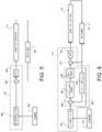
- Figure 8 shows blocks of the control unit 30 allowing to automatically perform the manoeuvre, according to an embodiment of the present invention.
- control unit 30 is electrically coupled to the joint actuators 17, to control them, and to the sensors 28, to receive from them the data of the joints 16.
- control unit 30 is further electrically coupled to the engine 20 to acquire data from it, as better described in the following.
- the control unit 30 (in particular, the elaboration unit 36) comprises an interpolator block 80, a first subtraction block 82 and a PID ("proportional-integral-derivative") block 84 of a known type.
- the interpolator block 80 implements the manoeuvre recording method 50, and in particular uses the position interest point set to calculate the reconstructed trajectory of the boom lift joint 17c, upon reception of the manoeuvre repeating command.
- the reconstructed trajectory is received (one reconstructed position at each time instant) as a sum input by the first subtraction block 82.
- the first subtraction block 82 further receives as a subtraction input the data from the sensors 28 (in the exemplary case here described, the angular position of the boom lift joint 17c) and outputs an error signal that is received as an input by the PID block 84.
- the PID block 84 elaborates the error signal in a per se known way and generates an actuator control signal that is sent to the joint actuators 17 (in the exemplary case here described, the boom lift joint 17c), to control them.
- control unit 30 can control the joint actuators 17 (and thus the controllable arm 12) based on the reconstructed trajectory, thus allowing to automatically repeat the recorded manoeuvre.
- the manoeuvre recording method 50 allows to record the manoeuvre executed by the user by only storing the position speed interest points and not the entire trajectory, so that the recorded trajectory can be automatically calculated and repeated when necessary. This reduces the duties and the fatigue of the user driving the vehicle 10, and prevents from manual errors when executing standard manoeuvres. Moreover, by using the position interest points and thus a variable sampling rate of the measured data curve, the information to be stored by the control unit 30 is strongly reduced (up to about -80% with respect to the known fixed sampling rate). Therefore, more manoeuvres can be recorded and stored by the vehicle 10 without the need of additional dedicated memories. Moreover, different manoeuvres having different movement speed (equivalently, the same manoeuvre comprising low-speed movements and high-speed movements) can be adequately and dynamically sampled, so that the reconstructed trajectory can better approximate the measured one.
- the filter for calculating the angular speed from the angular position improves the quality of the angular speed calculation.
- the noise and artefacts at high frequencies are strongly reduced with respect to the standard first time derivative approach.
- the coefficient ⁇ can range from a lower value to an upper value. The lower value impacts on the maximum frequency allowed to be kept into consideration, whilst the upper value affects the desired amount of noise reduction.
- such filter requires an easy digital implementation and low computational resources to be used.
- quadratic interpolation allows to reduce the overall jerk of the controllable arm 12 when the manoeuvre is automatically repeated.
- the quadratic interpolation of the angular position causes the angular speed to assume a trapezoidal profile, and thus an angular acceleration of the joints 16 is not impulsive and the jerk of the vehicle 10 is milder.
- the sensors 28 could include IMUs ("inertial measurement units”) or built-in encoders within the joint actuators 17 (to retrieve the displacement of each cylindrical joint actuator 17, thus being able to calculate the respective positions of the joint actuators 17).
- IMUs intial measurement units
- the linear and angular speed of the joints 16 can be directly measured, thus avoiding to perform the step S16 of the manoeuvre recording method 50, relative to the angular speed calculation.
- Figure 9 shows the blocks of the control unit 30 allowing to automatically perform the manoeuvre, according to known techniques of inverse kinematics.
- Figure 9 is similar to Figure 8 , but the control unit 30 (in details, the elaboration unit 36) further comprises a CLICK ("Closed Loop Inverse Kinematic") block 85.
- the CLICK block 85 is of a known type, and allows converting trajectories in the Cartesian space into trajectories in the joint space.
- the CLICK block 85 comprises a second subtraction block 86, a transposed Jacobian block 88, a gain propagator 90 and a direct kinematic block 92.
- the reconstructed trajectory, in the Cartesian space, from the interpolator 80 is received as a sum input by the second subtraction block 86, that further receives as a subtraction input a direct kinematic signal from the direct kinematic block 92 and generates as output a Cartesian trajectory error that is received as an input by the transposed Jacobian block 88.
- the transposed Jacobian block 88 converts through a transposed Jacobian matrix the Cartesian trajectory error into a joint trajectory error, which is amplified by the gain propagator block 90 and set as the sum input of the first subtraction block 82. Moreover, data from the sensors 28 are further received as input by the direct kinematic block 92 and converted by it into said direct kinematic signal, in the Cartesian space.
- the CLICK block 85 can be substituted by an IIK ("Iterative Inverse Kinematic") block, not shown and of a per se known type.
- IIK Intelligent Inverse Kinematic
- the time scale can be varied based on the actual engine speed (received by the interpolator block 80 as illustrated in Figures 8 and 9 ).
- This allows to take into account any variations of the speed of the engine 20, since the actual engine speed (i.e., the engine speed measured while automatically reproduce the reconstructed trajectory, at the time the manoeuvre is repeated) could be different with respect to the engine speed during trajectory recording (in the following, called recorded engine speed), and since the actual engine speed and/or the recorded engine speed could not be uniform in time.
- engine speed variations affect the trajectory recording by causing the time axes to accelerate or decelerate accordingly. Therefore, the engine speed of the recorded trajectory is used to compute a ratio between actual engine speed and the recorded engine speed.
- i the current step of the interpolator block 80
- k a time scale coefficient (in details, is a calibrated map function of the engine speed and depending on the physical features of hydraulic circuit 26)
- t i -1 the time instant immediately precedent to the current time instant t i
- ⁇ t i is a variable time increment of the interpolator block 80 at step t i
- s actual is the actual engine speed at step t i
- s record is the recorded engine speed at step t i of the reconstructed trajectory.
- the time scale of the reconstructed trajectory generated by the interpolator block 80 is a function of the actual engine speed.
- the manoeuvre recording button 21 could be placed in a place other than on the joystick 19 (e.g., on a dashboard or a steering wheel of the vehicle 10).
- the position of the joystick 19 instead of measuring data of the joints 16 through the sensors 28. Since the joystick 19 directly and deterministically controls the controllable arm 12, it is not required to measure the data of the joints 16; instead, it is sufficient to record the positions of the joystick 19 while the user executes the manoeuvre to be recorded.
- the curve of the positions of the joystick 19 is processed according to the manoeuvre recording method 50, so that the reconstructed trajectory of the joystick 19 can be calculated and used to repeat the manoeuvre, analogously to what has been previously described.
Landscapes
- Engineering & Computer Science (AREA)
- Mining & Mineral Resources (AREA)
- Mechanical Engineering (AREA)
- Civil Engineering (AREA)
- Structural Engineering (AREA)
- General Engineering & Computer Science (AREA)
- General Physics & Mathematics (AREA)
- Automation & Control Theory (AREA)
- Physics & Mathematics (AREA)
- Life Sciences & Earth Sciences (AREA)
- Paleontology (AREA)
- General Life Sciences & Earth Sciences (AREA)
- Operation Control Of Excavators (AREA)
- Recording Measured Values (AREA)
- Time Recorders, Dirve Recorders, Access Control (AREA)
- Navigation (AREA)
Abstract
Description
- The present invention relates to a method for recording a manoeuvre of an operable arm of a heavy vehicle.
- As known, a heavy vehicle provided with a multi-joint arm is suitable to perform different tasks due to its arm capability and its ability to manipulate, carry and dump a load. Examples of such heavy vehicle are a telehandler, an excavator or a wheel loader.
- Even if the manoeuvres that are carried out by the heavy vehicle are numerous and different between them, it usually happens that only a subset of them must be repeated for long periods. For example, considering the operation of truck loading performed by an excavator, several basic manoeuvres can be identified: load the bucket at a first variable position, rise the boom, displace the boom, dump the load at a fixed position, swing to a second variable position to load again the bucket, and repeat these steps. In this case, there are several common and repetitive paths that a vehicle can store and repeat automatically. Another example of repetitive operations is the Y-cycle of a telehandler, through which the telehandler can load the bucket with a desired product (e.g., grain), drive to the desired location and dump the load. Even though the driving operation depends on an operator driving the heavy vehicle and cannot be easily reproduced, several operations can be repeated in an automated way: rise the boom, extend the boom to reach the desired dump position, dump the bucket, lower to carry position, etc. Automatically performing some manoeuvres could result in a reduction of the operator's amount of work and distress, and in an efficiency improvement.
- By acquiring data from each joint of the arm, it is possible to record a manoeuvre and to automatically repeat it.
- Known solutions to record a manoeuvre comprise sampling such data at a fixed sampling rate to construct a trace, and repeating the recorded trace upon receiving a trigger by the operator. However, using a fixed sampling rate results in a conspicuous memory allocation and could cause the filling up of the on-board storage unit. For example, considering a telehandler having three joints (boom lift, telescope and carrier tilt) which performs a standard cycle of boom lifting, boom extension, load dumping and bucket shaking in about 10s and has an embedded vehicle controller working with a time cycle of about 10ms, a variable of about 16bit for each joint position (three in total), a memory allocation of about 6kbyte is required to store said standard cycle. In case several manoeuvres are stored, the required memory allocation increases accordingly.
- The heavy vehicles equipped with an automatic trajectory generator are provided with a finite data storage capability, and such solution of manoeuvre recording drastically reduces the available amount of internal memory. An external dedicated memory could be used to increase the data storage capability, but this also increases the overall cost and the complexity of the heavy vehicle.
- Moreover, the known manoeuvre recording do not take into account the nature of the manoeuvre to be recorded, and this leads to a non-optimal recording and execution of the manoeuvre. In particular, by reducing the sampling rate it is possible to reduce the required memory allocation, but manoeuvres comprising fast movements cannot be adequately recorded.
- An aim of the present invention is to satisfy the above mentioned needs.
- The aforementioned aim is reached by a method for recording a manoeuvre as claimed in the appended set of claims.
- For a better understanding of the present invention, preferred embodiments thereof are now described, purely by way of non-limiting example and with reference to the attached drawings, wherein:
-
Figure 1 is a perspective view of a heavy vehicle provided with a controllable arm, according to an embodiment of the present invention; -
Figure 2 is a block diagram schematically showing the heavy vehicle ofFigure 1 , according to an embodiment of the present invention; -
Figure 3 is a block diagram schematically showing a manoeuvre recording method executed by the heavy vehicle ofFigure 1 , according to an embodiment of the present invention; -
Figure 4 is a graphic showing the angular position of a joint of the controllable arm ofFigure 1 during a manoeuvre of the same, as a function of time; -
Figure 5 is a graphic showing the angular speed of said joint of the controllable arm ofFigure 1 , as a function of time; -
Figure 6 is a graphic showing the angular position of said joint of the controllable arm ofFigure 1 , as a function of time, where position interest points of the curve representing said angular position are identified; -
Figure 7 is a graphic showing the position interest points ofFigure 6 and a reconstructed trajectory of said joint of the controllable arm ofFigure 1 , as a function of time; and -
Figures 8-9 are block diagrams schematically showing control blocks of the heavy vehicle ofFigure 1 , according to respective embodiments of the present invention. -
Figure 1 shows, in a triaxial Cartesian reference system defined by axis X, Y and Z, avehicle 10 provided with acontrollable arm 12. In particular, thevehicle 10 is a heavy vehicle, such as a telehandler, an excavator or a wheel loader (Figure 1 shows a telehandler with abucket 14 moved through the controllable arm 12). - The
controllable arm 12 is provided with at least onejoint 16 actuated by a respective joint actuator 17 (hydraulic actuator, in particular a cylindrical actuator) coupled to thejoint 16. In details,Figure 1 shows thecontrollable arm 12 having three joints 16 (i.e., a tilt joint, a telescopic joint and a boom lift joint, indicated respectively with thereference numerals reference numerals - Moreover, the
vehicle 10 includes an inputcommand acquisition device 19, such as a joystick (in the following indicated as joystick 19), for example placed in a cabin 11 of thevehicle 10. According to an aspect of the present invention, thejoystick 19 comprises amanoeuvre recording button 21. During use, thevehicle 10 is driven by a user who controls thecontrollable arm 12 by providing an input command through thejoystick 19. As better described in the following, the user can further record a manoeuvre of thevehicle 10 by providing manoeuvre commands (e.g., a start recording signal and a stop recording signal) through themanoeuvre recording button 21. As a non-limiting example, the manoeuvre of thevehicle 10 starts to be recorded when the user presses themanoeuvre recording button 21 for a predefined period (i.e., provides the start recording signal), such as for 3 sec, and stops to be recorded when the user rapidly presses the manoeuvre recording button 21 (i.e., provides the stop recording signal), such as for less than 1 sec. - As illustrated in
Figure 2 , thevehicle 10 further comprises an engine 20 (e.g., a thermal engine) mechanically coupled in a per se known way both to adriveline 22 and to ahydraulic pump 24. Thehydraulic pump 24 is comprised in ahydraulic circuit 26 and provides hydraulic power to the joint actuators 17 (included themselves in the hydraulic circuit 26) in order to actuate thejoints 16 of thecontrollable arm 12. - One or
more sensors 28 are coupled to thecontrollable arm 12 so as to acquire data of thejoints 16 in the joint space. According to an embodiment of the present invention, illustrated inFigure 1 , thesensors 28 comprise a tiltangular sensor 28a coupled to thetilt joint 17a, atelescopic sensor 28b coupled to thetelescopic joint 17b, and a boomangular sensor 28c coupled to theboom lift joint 17c. The tiltangular sensor 28a and the boomangular sensor 28c acquire the angular positions of thetilt joint 17a and, respectively, of theboom lift joint 17c, and thetelescopic sensor 28b acquires data indicative of a telescopic extension of thetelescopic joint 17b. - A control unit 30 (e.g., a vehicle control unit or a dedicated controller or control unit) of the
vehicle 10 is electrically coupled to thesensors 28, thejoint actuators 17 and thejoystick 19. Thecontrol unit 30 acquires the input command and the manoeuvre commands by the user through thejoystick 19, acquires the data of thejoints 16 through thesensors 28, and controls the joint actuators 17 (thus, the controllable arm 12) as better described in the following. Optionally, thecontrol unit 30 further acquires engine data indicative of the status and working of theengine 20 from further sensors (not shown) coupled to theengine 20, and controlstransmission actuators 32 in a per se known way. Thetransmission actuators 32 are coupled to thedriveline 22 to control thedriveline 22 in a per se known way (an example of thetransmission actuators 32 are the hydraulic valves controlling the position of clutches of thevehicle 10 in order to engage a gear of thevehicle 10, selected by the user). As an example, thecontrol unit 30 comprises a data storage unit 34 (referred to in the following asmemory 34, such as a RAM memory) and anelaboration unit 36 electrically coupled between them. - During use, the
vehicle 10 is driven by the user and thecontrollable arm 12 is controlled through thejoystick 19. When said manoeuvre of thecontrollable arm 12 is to be recorded, the user provides the start recording signal through themanoeuvre recording button 21, executes the manoeuvre (i.e., operates thecontrollable arm 12 and thevehicle 10 according to the specific manoeuvre to be performed) and, at the end of the manoeuvre, provides the stop recording signal through themanoeuvre recording button 21. - More in details, a
manoeuvre recording method 50, illustrated inFigure 3 , is implemented by the control unit 30 (in particular, by the elaboration unit 36) to record said manoeuvre of thevehicle 10. - The
manoeuvre recording method 50 starts, at step S10, when the start recording signal is provided to thecontrol unit 30 through themanoeuvre recording button 21. - At step S12, consecutive to step S10, the
control unit 30 temporarily stores, e.g. in thememory 34, the data of thejoints 16 acquired through thesensors 28, while the user executes the manoeuvre by driving thevehicle 10 and controlling thecontrollable arm 12. - At step S14, consecutive to step S12, the stop recording signal is provided to the
control unit 30 through themanoeuvre recording button 21, and thecontrol unit 30 stops recording the data of thejoints 16. - Therefore, the
control unit 30 stores (until required, i.e. step S18 described in the following) the data of thejoints 16 during the period comprised between (and including) the start recording signal and the stop recording signal. - In the following, reference is made to the exemplary case in which the angular position of the
boom lift joint 17c is acquired through the boomangular sensor 28c and stored (Figure 4 ). Nevertheless, the following discussion analogously applies to the cases of recording the angular position of thetilt joint 17a through the tiltangular sensor 28a, or the telescopic extension of thetelescopic joint 17b through thetelescopic sensor 28b, or any simultaneous recording of the abovementioned data from thesensors 28. - In particular,
Figure 4 illustrates the behaviour, as a function of time, of the angular position of theboom lift joint 17c (in details, as an angular position variation from the angular position of theboom lift joint 17c when the start recording signal is received). The acquired curve of the angular position of theboom lift joint 17c starts at a start time Tstart (i.e., the time at which the start recording signal is received by the control unit 30) and ends at a stop time Tstop (i.e., the time at which the stop recording signal is received by the control unit 30). As an example, the acquired curve shows: a first portion between the start time Tstart and a first intermediate time T1, that is substantially rectilinear and with about zero slope; a second portion between the first intermediate time T1 and a second intermediate time T2, that is substantially rectilinear and with non-zero slope; and a third portion between the second intermediate time T2 and the stop time Tstop, that is substantially rectilinear and with about zero slope. Therefore, the angular position of the boom lift joint 17c is constant in the first portion at a first value P1, linearly varies in the second portion from the first value P1 to a second value P2, and is constant in the third portion at a second value P2. - At step S16, consecutive to step S14, an angular speed of the boom lift joint 17c is calculated as a function of the acquired angular position of the boom lift joint 17c.
- According to an embodiment, the angular speed is calculated as a first derivative of the acquired angular position of the boom lift joint 17c. According to a preferred embodiment, the angular speed is calculated by applying a filter to the acquired angular position of the boom lift joint 17c. Said filter approximates the first derivative behaviour at low frequencies (e.g., lower than about 10Hz) where the ratio between noise measurement and actual signal of the boom
angular sensor 28c is small (e.g., lower than about 10%), and at the same time limits a bandwidth of the angular speed at a predefined frequency in order to not amplify the noise at high frequencies (e.g., minimum noise attenuation of -20dB/dec). In particular, the filter is a second order band-pass filter, having the following mathematical form in Laplace domain: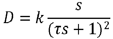
-
Figure 5 illustrates the behaviour, as a function of time, of the angular speed of the boom lift joint 17c calculated through said filter. The calculated curve of the angular speed shows: a first portion between the start time Tstart and about the first intermediate time T1, presenting values about a first value S1 (e.g., equal to zero, although several peaks and valleys can be noticed due to measurement noise); a second portion between about the first intermediate time T1 and about the second intermediate time T2, presenting values about a second value S2 different from the first value 51 (although several peaks and valleys can be noticed because of the noise within measurement); and a third portion between about the second intermediate time T2 and the stop time Tstop, presenting values at about the first value S1 (although several peaks and valleys can be noticed due to the noise in the measurement). Therefore, the angular speed of the boom lift joint 17c varies from the first value S1 to the second value S2 at about the first intermediate time T1 (in details, in a first time period at the first intermediate time T1, e.g. the first time period being comprised between 0.2 s and 5 s), and varies from the second value S2 to the first value S1 at about the second intermediate time T2 (in details, in a second time period at the second intermediate time T2, e.g. the second time period being comprised between 0.4 s and 10 s). - At step S18, consecutive to step S16, speed interest points (or speed relevant points, or speed focal points, or first speed interest points) of the curve of the angular speed of the boom lift joint 17c are calculated. The speed interest points are a plurality of points of the calculated curve of the angular speed, which are indicative of respective significant variations of the angular speed. In other words, each speed interest point is identified as a point of the angular speed curve, defined by two coordinates, i.e. a time instant and angular speed value. Each speed interest point is selected from the points of the angular speed curve so that its angular speed value presents, in absolute value, a speed difference with respect to the angular speed value of the immediately precedent speed interest point, that is greater than a predefined speed threshold. Therefore, each couple of speed interest points that are immediately consecutive to each other is indicative of said reciprocal speed difference being greater than the predefined speed difference. The first point of the angular speed curve (i.e., the point having as time instant the start time Tstart) is considered to be the first speed interest point of the speed interest point set, and the last point of the angular speed curve (i.e., the point having as time instant the stop time Tstop) is considered to be the last speed interest point of the speed interest point set.
- According to an embodiment of the present invention, the speed interest point set comprises the points of the angular speed curve for which the following relationship is satisfied:

angular sensor 28c; e.g., given the measurement error of the boomangular sensor 28c in terms of standard deviation σ, it is possible to approximate a as a=3·σ), ẏx is the speed value of the speed interest point at the time instant t (i.e., the considered speed interest point), and


- In details,
Figure 5 further shows the speed interest points, together with the angular speed curve. - Advantageously, the speed interest point set can also comprise one or more artefact interest points (or second speed interest points) if the angular speed curve presents at least one portion that is substantially constant for a long period (e.g., the first and the third portions). The artefact interest points are additional speed interest points for which the above-mentioned relationship is not satisfied, but which are considered and added to prevent manoeuvre reconstruction errors, as better specified in the following. In details, starting from the speed interest point set calculated according to the above-mentioned relationship, for each couple of immediately consecutive speed interest points xn and x n+1, a respective time distance Δt between them is determined (i.e., Δt = t x
n+1 - txn ), and it is determined whether such time distance Δt is greater than a threshold time distance Δtthres (e.g., equal to 500 ms). If Δt ≤ Δtthres , no artefact interest point is added between the immediately consecutive speed interest points xn and x n+1, and the successive couple of immediately consecutive speed interest points x n+1 and x n+2 is examined. If Δt > Δtthres , an artefact interest point xart is added between the immediately consecutive speed interest points xn and x n+1, at the time instant tart = txn + Δtthres , and the determination is repeated for the couple of speed interest points xart and x n+1. - In the following, the wording speed interest point set is used to consider both the speed interest points calculated according to the abovementioned relationship and the artefact interest points, if any. Therefore, the speed interest point set so calculated presents an agglomeration in time of speed interest points where the angular speed curve significantly varies, but no couple of speed interest points presents a relative time distance greater than the threshold time distance Δtthres .
- Moreover, at step S18 a position interest point set is calculated based on the speed interest point set, and is stored (e.g., in the memory 34) . In particular, position interest points are the points of the angular position curve whose time values correspond to the time values of the speed interest points of the speed interest point set. Therefore, each speed interest point is associated to a respective position interest point, in that they are placed at the same time instant in the time axis.
Figure 6 shows the position interest points, together with the same angular position curve ofFigure 4 . - At step S20, consecutive to step S18, a reconstructed curve of the angular positions of the boom lift joint 17c is calculated based on the position interest points obtained at step S18. In particular, the reconstructed curve is obtained through interpolation of the position interest points.
- According to an embodiment, a linear, cubic, spline, or exponential interpolation is used. According to a preferred embodiment, exemplarily described in details in the following, a quadratic interpolation is used, so as to reduce the jerk of the
controllable arm 12 when the reconstructed manoeuvre is automatically executed. - In details, the quadratic (or parabolic) interpolation is an interpolation performed through the following quadratic formula:

n ≤ i < t xn+1). If the position interest point set comprises N position interest points, 1 ≤ n ≤ N - 2 and the coefficient calculation stops at n = N - 2. For time instants successive to the position interest point x N-2, the values of the reconstructed curve are calculated based on the last calculated coefficients a,b,c (i.e., those calculated for the position interest point x N-2). Therefore, each position interest point xn is associated to respective coefficients a,b,c that are used to calculate the reconstructed curve of the angular positions of the boom lift joint 17c in the time interval comprised between the position interest point xn and the immediately consecutive position interest point x n+1. - The
manoeuvre recording method 50 thus ends with the calculation of the reconstructed curve (or trajectory) of the angular positions of the boom lift joint 17c. The reconstructed curve, illustrated inFigure 7 , is a reconstructed trajectory (i.e., a set point) of the boom lift joint 17c during the manoeuvre executed by the user, and it can be automatically repeated to reproduce said manoeuvre without the need of the user's intervention. - In particular, the reconstructed trajectory is generated by the
control unit 30 whenever the manoeuvre has to be automatically executed. In further details, thecontrol unit 30 controls thevehicle 10 to automatically repeat the manoeuvre, based on the reconstructed trajectory, upon receiving a manoeuvre repeating command provided by the user through, for example, the manoeuvre recording button 21 (e.g., the user presses themanoeuvre recording button 21 for about 1 sec). Therefore, when, during the use of thevehicle 10, thecontrol unit 30 receives the manoeuvre repeating command from the user, thecontrol unit 30 uses the position interest point set (stored in the memory 34) to calculate the reconstructed trajectory and to use it to control thecontrollable arm 12. - This allows to store in the
memory 34 only the time instants of speed interest point set and the angular position at each of these time instants, and not the entire angular position curve or the reconstructed trajectory. -
Figure 8 shows blocks of thecontrol unit 30 allowing to automatically perform the manoeuvre, according to an embodiment of the present invention. - As shown in
Figure 8 , thecontrol unit 30 is electrically coupled to thejoint actuators 17, to control them, and to thesensors 28, to receive from them the data of thejoints 16. Optionally, thecontrol unit 30 is further electrically coupled to theengine 20 to acquire data from it, as better described in the following. - The control unit 30 (in particular, the elaboration unit 36) comprises an
interpolator block 80, afirst subtraction block 82 and a PID ("proportional-integral-derivative") block 84 of a known type. Theinterpolator block 80 implements themanoeuvre recording method 50, and in particular uses the position interest point set to calculate the reconstructed trajectory of the boom lift joint 17c, upon reception of the manoeuvre repeating command. The reconstructed trajectory is received (one reconstructed position at each time instant) as a sum input by thefirst subtraction block 82. Thefirst subtraction block 82 further receives as a subtraction input the data from the sensors 28 (in the exemplary case here described, the angular position of the boom lift joint 17c) and outputs an error signal that is received as an input by thePID block 84. ThePID block 84 elaborates the error signal in a per se known way and generates an actuator control signal that is sent to the joint actuators 17 (in the exemplary case here described, the boom lift joint 17c), to control them. - Therefore, the
control unit 30 can control the joint actuators 17 (and thus the controllable arm 12) based on the reconstructed trajectory, thus allowing to automatically repeat the recorded manoeuvre. - From what has been described and illustrated previously, the advantages of the present invention are evident.
- The
manoeuvre recording method 50 allows to record the manoeuvre executed by the user by only storing the position speed interest points and not the entire trajectory, so that the recorded trajectory can be automatically calculated and repeated when necessary. This reduces the duties and the fatigue of the user driving thevehicle 10, and prevents from manual errors when executing standard manoeuvres. Moreover, by using the position interest points and thus a variable sampling rate of the measured data curve, the information to be stored by thecontrol unit 30 is strongly reduced (up to about -80% with respect to the known fixed sampling rate). Therefore, more manoeuvres can be recorded and stored by thevehicle 10 without the need of additional dedicated memories. Moreover, different manoeuvres having different movement speed (equivalently, the same manoeuvre comprising low-speed movements and high-speed movements) can be adequately and dynamically sampled, so that the reconstructed trajectory can better approximate the measured one. - By including the artefact interest points, reconstruction errors during interpolation are reduced by increasing the number of constraints to be applied also along substantially rectilinear portions of the angular speed curve.
- Moreover, using the filter for calculating the angular speed from the angular position improves the quality of the angular speed calculation. In fact, the noise and artefacts at high frequencies are strongly reduced with respect to the standard first time derivative approach. In particular, the coefficient τ can range from a lower value to an upper value. The lower value impacts on the maximum frequency allowed to be kept into consideration, whilst the upper value affects the desired amount of noise reduction. Moreover, such filter requires an easy digital implementation and low computational resources to be used.
- Furthermore, using the quadratic interpolation allows to reduce the overall jerk of the
controllable arm 12 when the manoeuvre is automatically repeated. In fact, the quadratic interpolation of the angular position causes the angular speed to assume a trapezoidal profile, and thus an angular acceleration of thejoints 16 is not impulsive and the jerk of thevehicle 10 is milder. - Finally, it is clear that modifications and variations may be made to what has been described and illustrated herein, without thereby departing from the scope of the present invention, as defined in the annexed claims.
- In particular, the
sensors 28 could include IMUs ("inertial measurement units") or built-in encoders within the joint actuators 17 (to retrieve the displacement of each cylindricaljoint actuator 17, thus being able to calculate the respective positions of the joint actuators 17). By using IMUs, the linear and angular speed of thejoints 16 can be directly measured, thus avoiding to perform the step S16 of themanoeuvre recording method 50, relative to the angular speed calculation. - Moreover, the
sensors 28 could acquire data of thejoints 16 in the Cartesian space, and not in the joint space as previously described. In this case,Figure 9 shows the blocks of thecontrol unit 30 allowing to automatically perform the manoeuvre, according to known techniques of inverse kinematics. In details,Figure 9 is similar toFigure 8 , but the control unit 30 (in details, the elaboration unit 36) further comprises a CLICK ("Closed Loop Inverse Kinematic")block 85. TheCLICK block 85 is of a known type, and allows converting trajectories in the Cartesian space into trajectories in the joint space. In details, theCLICK block 85 comprises asecond subtraction block 86, a transposedJacobian block 88, again propagator 90 and a directkinematic block 92. The reconstructed trajectory, in the Cartesian space, from theinterpolator 80 is received as a sum input by thesecond subtraction block 86, that further receives as a subtraction input a direct kinematic signal from the directkinematic block 92 and generates as output a Cartesian trajectory error that is received as an input by the transposedJacobian block 88. The transposedJacobian block 88 converts through a transposed Jacobian matrix the Cartesian trajectory error into a joint trajectory error, which is amplified by thegain propagator block 90 and set as the sum input of thefirst subtraction block 82. Moreover, data from thesensors 28 are further received as input by the directkinematic block 92 and converted by it into said direct kinematic signal, in the Cartesian space. - Alternatively, the
CLICK block 85 can be substituted by an IIK ("Iterative Inverse Kinematic") block, not shown and of a per se known type. - Furthermore, when executing the reconstructed trajectory, its time scale can be varied based on the actual engine speed (received by the
interpolator block 80 as illustrated inFigures 8 and 9 ). This allows to take into account any variations of the speed of theengine 20, since the actual engine speed (i.e., the engine speed measured while automatically reproduce the reconstructed trajectory, at the time the manoeuvre is repeated) could be different with respect to the engine speed during trajectory recording (in the following, called recorded engine speed), and since the actual engine speed and/or the recorded engine speed could not be uniform in time. In fact, engine speed variations affect the trajectory recording by causing the time axes to accelerate or decelerate accordingly. Therefore, the engine speed of the recorded trajectory is used to compute a ratio between actual engine speed and the recorded engine speed. Such ratio influences the time increment that theinterpolator block 80 uses to reproduce the reconstructed trajectory. More in details, each current time instant ti is calculated as ti = t i-1 + Δti , with:
interpolator block 80, k is a time scale coefficient (in details, is a calibrated map function of the engine speed and depending on the physical features of hydraulic circuit 26), t i-1 is the time instant immediately precedent to the current time instant ti , Δti is a variable time increment of theinterpolator block 80 at step ti , sactual is the actual engine speed at step ti and srecord is the recorded engine speed at step ti of the reconstructed trajectory. In other words, the time scale of the reconstructed trajectory generated by theinterpolator block 80 is a function of the actual engine speed. - The
manoeuvre recording button 21 could be placed in a place other than on the joystick 19 (e.g., on a dashboard or a steering wheel of the vehicle 10). - Moreover, it also possible to record the position of the
joystick 19 instead of measuring data of thejoints 16 through thesensors 28. Since thejoystick 19 directly and deterministically controls thecontrollable arm 12, it is not required to measure the data of thejoints 16; instead, it is sufficient to record the positions of thejoystick 19 while the user executes the manoeuvre to be recorded. The curve of the positions of thejoystick 19 is processed according to themanoeuvre recording method 50, so that the reconstructed trajectory of thejoystick 19 can be calculated and used to repeat the manoeuvre, analogously to what has been previously described.
Claims (18)
- Method (50) for recording a manoeuvre of an operable arm (12) of a heavy vehicle (10), the operable arm (12) being operable through at least one joint (16) of the operable arm (12), the method comprising the steps of:- while a user executes the manoeuvre by operating the operable arm (12), acquiring (S12), by a control unit (30) of the heavy vehicle (10) and for each joint (16), a respective joint position signal indicative of a trajectory of said joint (16), through a respective first sensor (28) coupled to the operable arm (12);- for each joint position signal, determining (S16) a respective joint speed signal indicative of the speed of said joint (16);- for each joint speed signal, determining (S18), by the control unit (30), a respective plurality of first speed interest points of the joint speed signal, each couple of first speed interest points that are immediately consecutive to each other being indicative of a reciprocal speed difference greater than a threshold speed difference, the plurality of first speed interest points having a respective plurality of first time values;- associating (S18) to each plurality of first speed interest points, by the control unit (30), a respective plurality of first position interest points of the joint position signal, having the first time values; and- generating (S20), by the control unit (30) and based on each plurality of first position interest points, a respective recorded position signal indicative of the trajectory of said joint (16),
wherein, when the at least one joint (16) is actuated by the control unit (30) based on the respective recorded position signal, said manoeuvre is automatically executed. - Method according to claim 1, wherein the step of determining (S18) the first speed interest points comprises, in order to calculate each immediately successive speed interest point starting from the considered speed interest point:a. calculating an integral average of the joint speed signal, from the first time value of the considered first speed interest point to an intermediate time value successive to the first time value of the considered first speed interest point;b. calculating a speed absolute difference between the integral average and the speed of said joint (16) at the considered first speed interest point; andif the speed absolute difference is lower than or equal to a predefined speed difference, repeating the steps a. and b. by updating the intermediate time value to a further time value that is successive to the intermediate time value, orif the speed absolute difference is greater than the predefined speed difference, setting the intermediate time value and the speed of said joint (16) at the intermediate time value as coordinates of said immediately successive speed interest point.
- Method according to claim 1 or 2, wherein the step of acquiring (S12) the joint position signal comprises starting acquiring the joint position signal upon receipt, by the control unit (30), of a start recording signal provided by the user, and further comprises ending acquiring the joint position signal upon receipt, by the control unit (30), of a stop recording signal provided by the user.
- Method according to anyone of the preceding claims, wherein a first point and a last point of the joint speed signal are first speed interest points, and a first point and a last point of the joint position signal are first position interest points.
- Method according to anyone of the preceding claims, further comprising the steps of:- for each joint speed signal, determining (S18), by the control unit (30), one or more second speed interest points of the joint speed signal if at least one of said couples of first speed interest points that are immediately consecutive to each other presents a reciprocal time difference greater than a threshold time difference, the one or more second speed interest points having respective second time values;- associating (S18) to each second speed interest point, by the control unit (30), a respective second position interest point of the joint position signal, having the respective second time value; and- generating (S20), by the control unit (30), the respective recorded position signal further based on each respective second position interest point.
- Method according to claim 5, wherein the step of determining (S18) one or more second speed interest points comprises, for each couple of first speed interest points:a. calculating said reciprocal time difference (Δt) between the first time values of the first speed interest points of said couple;b. determining if the reciprocal time difference (Δt) is greater than a threshold time difference (Δtthres ), andif the reciprocal time difference (Δt) is lower than or equal to the threshold time difference (Δtthres ), no second speed interest point is added, orif the reciprocal time difference (Δt) is greater than the threshold time difference (Δtthres ), the one or more second speed interest points are added between the first speed interest points of said couple.
- Method according to claim 6, wherein, if the reciprocal time difference (Δt) is greater than the threshold time difference (Δtthres ): the second speed interest point is added having the second time value equal to the sum of the threshold time difference (Δtthres ) and of the first time value of the first first speed interest point of said couple; and the steps a. and b. of claim 6 are repeated for a successive couple of first speed interest points that are immediately consecutive to each other, said successive couple comprising the added second speed interest point and the second first speed interest point of the couple.
- Method according to anyone of the preceding claims, wherein the step of determining (S16) the joint speed signal comprises calculating a first order time derivative of the joint position signal.
- Method according to anyone of claims 1-7, wherein the step of determining (S16) the joint speed signal comprises applying a second order band-pass filter to the joint position signal.
- Method according to anyone of claims 1-7, wherein the step of determining (S16) the joint speed signal comprises acquiring, by the control unit (30), the joint speed signal through a respective second sensor coupled to the operable arm (12) .
- Method according to anyone of the preceding claims, further comprising the step of storing each plurality of first position interest points in a memory (34) of the control unit (30) .
- Method according to anyone of the preceding claims, wherein the step of generating (S20) the respective recorded position signal comprises calculating a quadratic interpolation of the first position interest points.
- Method according to anyone of the preceding claims, wherein the step of generating (S20) the respective recorded position signal comprises calculating a time scale of the recorded position signal as a function of an actual speed of an engine (20) of the heavy vehicle (10).
- Computer program product storable in a control unit (30), the computer program being designed so that, when executed, the control unit (30) becomes configured to perform a method according to anyone of claims 1-13.
- Control unit (30) configured to:- while a user executes a manoeuvre by operating an operable arm (12) of a heavy vehicle (10), acquire (S12) for each joint (16) of the operable arm (12) a respective joint position signal indicative of a trajectory of said joint (16), through a respective first sensor (28) coupled to the operable arm (12) and operatively couplable to the control unit (30);- for each joint position signal, determine (S16) a respective joint speed signal indicative of the speed of said joint (16);- for each joint speed signal, determine (S18) a respective plurality of first speed interest points of the joint speed signal, each couple of first speed interest points that are immediately consecutive to each other being indicative of a reciprocal speed difference greater than a threshold speed difference, the plurality of first speed interest points having a respective plurality of first time values;- associate (S18) to each plurality of first speed interest points a respective plurality of first position interest points of the joint position signal, having the first time values; and- generate (S20), based on each plurality of first position interest points, a respective recorded position signal indicative of the trajectory of said joint (16),wherein, when the at least one joint (16) is actuated by the control unit (30) based on the respective recorded position signal, said manoeuvre is automatically executed.
- Heavy vehicle (10) comprising a control unit (30), according to claim 15, and said operable arm (12).
- Heavy vehicle according to claim 16, wherein the operable arm (12) is controllable by the control unit (30) based on the one or more recorded position signals.
- Heavy vehicle according to claim 16 or 17, further comprising an input command acquisition device (19) that is the operable arm (12).
Applications Claiming Priority (1)
| Application Number | Priority Date | Filing Date | Title |
|---|---|---|---|
| IT102021000005975A IT202100005975A1 (en) | 2021-03-12 | 2021-03-12 | METHOD OF RECORDING A MANEUVER OF AN ACTIVATED ARM OF A HEAVY DUTY VEHICLE |
Publications (2)
| Publication Number | Publication Date |
|---|---|
| EP4056328A1 true EP4056328A1 (en) | 2022-09-14 |
| EP4056328B1 EP4056328B1 (en) | 2025-08-27 |
Family
ID=75850620
Family Applications (1)
| Application Number | Title | Priority Date | Filing Date |
|---|---|---|---|
| EP22161475.3A Active EP4056328B1 (en) | 2021-03-12 | 2022-03-10 | Method for recording a manoeuvre of an operable arm of a heavy vehicle |
Country Status (2)
| Country | Link |
|---|---|
| EP (1) | EP4056328B1 (en) |
| IT (1) | IT202100005975A1 (en) |
Citations (2)
| Publication number | Priority date | Publication date | Assignee | Title |
|---|---|---|---|---|
| US20200122325A1 (en) * | 2018-10-17 | 2020-04-23 | Kabushiki Kaisha Yaskawa Denki | Robot system and robot control method |
| EP3770333A1 (en) * | 2018-03-20 | 2021-01-27 | Sumitomo Heavy Industries, Ltd. | Shovel |
-
2021
- 2021-03-12 IT IT102021000005975A patent/IT202100005975A1/en unknown
-
2022
- 2022-03-10 EP EP22161475.3A patent/EP4056328B1/en active Active
Patent Citations (2)
| Publication number | Priority date | Publication date | Assignee | Title |
|---|---|---|---|---|
| EP3770333A1 (en) * | 2018-03-20 | 2021-01-27 | Sumitomo Heavy Industries, Ltd. | Shovel |
| US20200122325A1 (en) * | 2018-10-17 | 2020-04-23 | Kabushiki Kaisha Yaskawa Denki | Robot system and robot control method |
Non-Patent Citations (1)
| Title |
|---|
| SICILIANO BRUNO ET AL: "Robotics Modelling, Planning and Control - Chapter 4", ROBOTICS : MODELLING, PLANNING AND CONTROL, 31 December 2009 (2009-12-31), UK, pages 160 - 189, XP055859539, ISBN: 978-1-84628-641-4, Retrieved from the Internet <URL:https://link.springer.com/book/10.1007/978-1-84628-642-1> DOI: 10.1007/978-1-84628-642-1 * |
Also Published As
| Publication number | Publication date |
|---|---|
| IT202100005975A1 (en) | 2022-09-12 |
| EP4056328B1 (en) | 2025-08-27 |
Similar Documents
| Publication | Publication Date | Title |
|---|---|---|
| US6211471B1 (en) | Control system for automatically controlling a work implement of an earthmoving machine to capture, lift and dump material | |
| US11041291B2 (en) | Controlling a work machine based on sensed variables | |
| US11174618B2 (en) | System and method for automated payload target tipoff | |
| US9938692B2 (en) | Wheel loader payload measurement system linkage acceleration compensation | |
| US8340872B2 (en) | Control system and method for capturing partial bucket loads in automated loading cycle | |
| US5784945A (en) | Method and apparatus for determining a valve transform | |
| KR100737250B1 (en) | Controller for operating machine of construction machinery, method for controlling construction machinery, and recording medium storing program allowing computer to execute this method | |
| EP3715534B1 (en) | System and method for automatic weight monitoring and control during a material moving operation | |
| US5908458A (en) | Automated system and method for control of movement using parameterized scripts | |
| JP3614171B2 (en) | Multivariate control of multistage free link mechanism | |
| US8948977B2 (en) | Systems and methods for machine implement control | |
| CN112424430A (en) | Control device, loading machine, and control method | |
| AU2018274872B2 (en) | System for controlling a drive operation of a machine | |
| CN113761673A (en) | Method and system for determining process data of a work process performed by a work machine | |
| EP3102744B1 (en) | Autonomous loading vehicle controller | |
| EP4056328B1 (en) | Method for recording a manoeuvre of an operable arm of a heavy vehicle | |
| US11624169B2 (en) | Excavator with improved movement sensing | |
| CN110258713A (en) | Method for Acquiring Position Parameter Data of Loader Working Device | |
| JP4820907B2 (en) | Construction machine work machine control device and construction machine work machine control method | |
| CN114428483B (en) | Remote control end force feedback control method, device and system for working machinery | |
| EP4148193A1 (en) | Method for invoking a weighing function of a working machine and working machine | |
| US20220259833A1 (en) | Posture Estimation Method, Posture Estimation Device, And Movable Device | |
| CN115094971B (en) | Excavation material weighing position calibration method and system, weighing method, excavator | |
| Elezaby | Virtual autonomous operator model for construction equipment applications | |
| EP4575100A1 (en) | Method for supporting completion of a mission of an agricultural or work vehicle and a control unit implementing the method |
Legal Events
| Date | Code | Title | Description |
|---|---|---|---|
| PUAI | Public reference made under article 153(3) epc to a published international application that has entered the european phase |
Free format text: ORIGINAL CODE: 0009012 |
|
| STAA | Information on the status of an ep patent application or granted ep patent |
Free format text: STATUS: THE APPLICATION HAS BEEN PUBLISHED |
|
| AK | Designated contracting states |
Kind code of ref document: A1 Designated state(s): AL AT BE BG CH CY CZ DE DK EE ES FI FR GB GR HR HU IE IS IT LI LT LU LV MC MK MT NL NO PL PT RO RS SE SI SK SM TR |
|
| STAA | Information on the status of an ep patent application or granted ep patent |
Free format text: STATUS: REQUEST FOR EXAMINATION WAS MADE |
|
| 17P | Request for examination filed |
Effective date: 20230314 |
|
| RBV | Designated contracting states (corrected) |
Designated state(s): AL AT BE BG CH CY CZ DE DK EE ES FI FR GB GR HR HU IE IS IT LI LT LU LV MC MK MT NL NO PL PT RO RS SE SI SK SM TR |
|
| RAP3 | Party data changed (applicant data changed or rights of an application transferred) |
Owner name: CNH INDUSTRIAL ITALIA S.P.A. |
|
| GRAP | Despatch of communication of intention to grant a patent |
Free format text: ORIGINAL CODE: EPIDOSNIGR1 |
|
| STAA | Information on the status of an ep patent application or granted ep patent |
Free format text: STATUS: GRANT OF PATENT IS INTENDED |
|
| INTG | Intention to grant announced |
Effective date: 20250318 |
|
| GRAS | Grant fee paid |
Free format text: ORIGINAL CODE: EPIDOSNIGR3 |
|
| GRAA | (expected) grant |
Free format text: ORIGINAL CODE: 0009210 |
|
| STAA | Information on the status of an ep patent application or granted ep patent |
Free format text: STATUS: THE PATENT HAS BEEN GRANTED |
|
| AK | Designated contracting states |
Kind code of ref document: B1 Designated state(s): AL AT BE BG CH CY CZ DE DK EE ES FI FR GB GR HR HU IE IS IT LI LT LU LV MC MK MT NL NO PL PT RO RS SE SI SK SM TR |
|
| REG | Reference to a national code |
Ref country code: CH Ref legal event code: EP |
|
| REG | Reference to a national code |
Ref country code: DE Ref legal event code: R096 Ref document number: 602022020038 Country of ref document: DE |
|
| REG | Reference to a national code |
Ref country code: IE Ref legal event code: FG4D |
|
| REG | Reference to a national code |
Ref country code: NL Ref legal event code: MP Effective date: 20250827 |
|
| PG25 | Lapsed in a contracting state [announced via postgrant information from national office to epo] |
Ref country code: IS Free format text: LAPSE BECAUSE OF FAILURE TO SUBMIT A TRANSLATION OF THE DESCRIPTION OR TO PAY THE FEE WITHIN THE PRESCRIBED TIME-LIMIT Effective date: 20251227 |
|
| PG25 | Lapsed in a contracting state [announced via postgrant information from national office to epo] |
Ref country code: NO Free format text: LAPSE BECAUSE OF FAILURE TO SUBMIT A TRANSLATION OF THE DESCRIPTION OR TO PAY THE FEE WITHIN THE PRESCRIBED TIME-LIMIT Effective date: 20251127 |
|
| REG | Reference to a national code |
Ref country code: LT Ref legal event code: MG9D |
|
| PG25 | Lapsed in a contracting state [announced via postgrant information from national office to epo] |
Ref country code: PT Free format text: LAPSE BECAUSE OF FAILURE TO SUBMIT A TRANSLATION OF THE DESCRIPTION OR TO PAY THE FEE WITHIN THE PRESCRIBED TIME-LIMIT Effective date: 20251229 |
|
| PG25 | Lapsed in a contracting state [announced via postgrant information from national office to epo] |
Ref country code: FI Free format text: LAPSE BECAUSE OF FAILURE TO SUBMIT A TRANSLATION OF THE DESCRIPTION OR TO PAY THE FEE WITHIN THE PRESCRIBED TIME-LIMIT Effective date: 20250827 |
|
| PG25 | Lapsed in a contracting state [announced via postgrant information from national office to epo] |
Ref country code: HR Free format text: LAPSE BECAUSE OF FAILURE TO SUBMIT A TRANSLATION OF THE DESCRIPTION OR TO PAY THE FEE WITHIN THE PRESCRIBED TIME-LIMIT Effective date: 20250827 Ref country code: NL Free format text: LAPSE BECAUSE OF FAILURE TO SUBMIT A TRANSLATION OF THE DESCRIPTION OR TO PAY THE FEE WITHIN THE PRESCRIBED TIME-LIMIT Effective date: 20250827 |
|
| PG25 | Lapsed in a contracting state [announced via postgrant information from national office to epo] |
Ref country code: GR Free format text: LAPSE BECAUSE OF FAILURE TO SUBMIT A TRANSLATION OF THE DESCRIPTION OR TO PAY THE FEE WITHIN THE PRESCRIBED TIME-LIMIT Effective date: 20251128 |
|
| PG25 | Lapsed in a contracting state [announced via postgrant information from national office to epo] |
Ref country code: SE Free format text: LAPSE BECAUSE OF FAILURE TO SUBMIT A TRANSLATION OF THE DESCRIPTION OR TO PAY THE FEE WITHIN THE PRESCRIBED TIME-LIMIT Effective date: 20250827 |
|
| PG25 | Lapsed in a contracting state [announced via postgrant information from national office to epo] |
Ref country code: LV Free format text: LAPSE BECAUSE OF FAILURE TO SUBMIT A TRANSLATION OF THE DESCRIPTION OR TO PAY THE FEE WITHIN THE PRESCRIBED TIME-LIMIT Effective date: 20250827 |
|
| PG25 | Lapsed in a contracting state [announced via postgrant information from national office to epo] |
Ref country code: BG Free format text: LAPSE BECAUSE OF FAILURE TO SUBMIT A TRANSLATION OF THE DESCRIPTION OR TO PAY THE FEE WITHIN THE PRESCRIBED TIME-LIMIT Effective date: 20250827 Ref country code: PL Free format text: LAPSE BECAUSE OF FAILURE TO SUBMIT A TRANSLATION OF THE DESCRIPTION OR TO PAY THE FEE WITHIN THE PRESCRIBED TIME-LIMIT Effective date: 20250827 |
|
| PG25 | Lapsed in a contracting state [announced via postgrant information from national office to epo] |
Ref country code: RS Free format text: LAPSE BECAUSE OF FAILURE TO SUBMIT A TRANSLATION OF THE DESCRIPTION OR TO PAY THE FEE WITHIN THE PRESCRIBED TIME-LIMIT Effective date: 20251127 |
|
| PG25 | Lapsed in a contracting state [announced via postgrant information from national office to epo] |
Ref country code: ES Free format text: LAPSE BECAUSE OF FAILURE TO SUBMIT A TRANSLATION OF THE DESCRIPTION OR TO PAY THE FEE WITHIN THE PRESCRIBED TIME-LIMIT Effective date: 20250827 |
|
| REG | Reference to a national code |
Ref country code: AT Ref legal event code: MK05 Ref document number: 1829470 Country of ref document: AT Kind code of ref document: T Effective date: 20250827 |
|
| PG25 | Lapsed in a contracting state [announced via postgrant information from national office to epo] |
Ref country code: SM Free format text: LAPSE BECAUSE OF FAILURE TO SUBMIT A TRANSLATION OF THE DESCRIPTION OR TO PAY THE FEE WITHIN THE PRESCRIBED TIME-LIMIT Effective date: 20250827 |
|
| PGFP | Annual fee paid to national office [announced via postgrant information from national office to epo] |
Ref country code: GB Payment date: 20260319 Year of fee payment: 5 |
|
| PG25 | Lapsed in a contracting state [announced via postgrant information from national office to epo] |
Ref country code: DK Free format text: LAPSE BECAUSE OF FAILURE TO SUBMIT A TRANSLATION OF THE DESCRIPTION OR TO PAY THE FEE WITHIN THE PRESCRIBED TIME-LIMIT Effective date: 20250827 |
|
| PGFP | Annual fee paid to national office [announced via postgrant information from national office to epo] |
Ref country code: DE Payment date: 20260320 Year of fee payment: 5 |
|
| PG25 | Lapsed in a contracting state [announced via postgrant information from national office to epo] |
Ref country code: AT Free format text: LAPSE BECAUSE OF FAILURE TO SUBMIT A TRANSLATION OF THE DESCRIPTION OR TO PAY THE FEE WITHIN THE PRESCRIBED TIME-LIMIT Effective date: 20250827 |
|
| PGFP | Annual fee paid to national office [announced via postgrant information from national office to epo] |
Ref country code: IT Payment date: 20260320 Year of fee payment: 5 |
|
| PGFP | Annual fee paid to national office [announced via postgrant information from national office to epo] |
Ref country code: FR Payment date: 20260323 Year of fee payment: 5 |
|
| PG25 | Lapsed in a contracting state [announced via postgrant information from national office to epo] |
Ref country code: CZ Free format text: LAPSE BECAUSE OF FAILURE TO SUBMIT A TRANSLATION OF THE DESCRIPTION OR TO PAY THE FEE WITHIN THE PRESCRIBED TIME-LIMIT Effective date: 20250827 |
|
| PG25 | Lapsed in a contracting state [announced via postgrant information from national office to epo] |
Ref country code: SK Free format text: LAPSE BECAUSE OF FAILURE TO SUBMIT A TRANSLATION OF THE DESCRIPTION OR TO PAY THE FEE WITHIN THE PRESCRIBED TIME-LIMIT Effective date: 20250827 Ref country code: EE Free format text: LAPSE BECAUSE OF FAILURE TO SUBMIT A TRANSLATION OF THE DESCRIPTION OR TO PAY THE FEE WITHIN THE PRESCRIBED TIME-LIMIT Effective date: 20250827 |
|
| REG | Reference to a national code |
Ref country code: DE Ref legal event code: R097 Ref document number: 602022020038 Country of ref document: DE |
|
| PG25 | Lapsed in a contracting state [announced via postgrant information from national office to epo] |
Ref country code: LT Free format text: LAPSE BECAUSE OF FAILURE TO SUBMIT A TRANSLATION OF THE DESCRIPTION OR TO PAY THE FEE WITHIN THE PRESCRIBED TIME-LIMIT Effective date: 20250827 |
|
| PLBE | No opposition filed within time limit |
Free format text: ORIGINAL CODE: 0009261 |
|
| STAA | Information on the status of an ep patent application or granted ep patent |
Free format text: STATUS: NO OPPOSITION FILED WITHIN TIME LIMIT |
|
| REG | Reference to a national code |
Ref country code: CH Ref legal event code: L10 Free format text: ST27 STATUS EVENT CODE: U-0-0-L10-L00 (AS PROVIDED BY THE NATIONAL OFFICE) Effective date: 20260708 |
|
| 26N | No opposition filed |
Effective date: 20260528 |